
Loading ...
Loading ...
Loading ...
ENGLISH
9
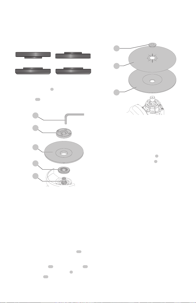
the spindle so that the raised section (pilot) fits into the
center of the wheel. If the wheel you are installing is 1/8"
(3.17mm) thick or less, place the threaded locking flange
on the spindle so that the raised section (pilot) is not against
thewheel.
Fig. E
Over 1/8" (3.17mm)
wheels
Backing Flange
Locking flange
1/8" Or less (3.17mm)
wheels
Backing Flange
Locking flange
5. While depressing the spindle lock button, tighten the
threaded locking flange
4
:
- Tighten standard threaded locking flange using
awrench
15
.
6. To remove the wheel, depress the spindle lock button
and loosen the threaded lockingflange.
Fig. E
15
4
14
3
1
Mounting Sanding Backing Pads (Fig.F)
NOTE: Use of a guard with sanding discs that use backing
pads, often called fiber resin discs, is not required. Since a
guard is not required for these accessories, the guard may or
may not fit correctly ifused.
WARNING: Failure to properly seat the clamp nut
and/or pad could result in serious injury (or damage
to the tool or wheel).
WARNING: Proper guard must be reinstalled for
grinding wheel, cutting wheel, sanding flap disc,
wire brush or wire wheel applications after sanding
applications arecomplete.
1. Place or appropriately thread backing pad
16
on
thespindle (backing flange and threaded locking flange
are not used).
2. Place the sanding disc
17
on the backing pad
16
.
3. While depressing spindle lock button
2
, thread the
sanding clamp nut
18
on spindle, piloting the raised
hub on the clamp nut into the center of san ding disc
and backingpad.
4. Tighten the clamp nut by hand. Then depress the
spindle lock button while turning the sanding disc until
the sanding disc and clamp nut aresnug.
5. To remove the wheel, grasp and turn the backing
pad and sanding pad while depressing the spindle
lockbutton.
Fig. F
18
17
16
Mounting and Removing Hubbed
Wheels (Fig. A)
Hubbed wheels install directly on the spindle (backing
flange and threaded locking flange are not used). Thread of
accessory must match thread ofspindle. Use only wheels
provided with a 5/8"-11 threaded hub.
1. Remove backing flange by pulling away fromtool.
2. Thread the wheel on the spindle
1
byhand.
3. Depress the spindle lock button
2
and use a wrench to
tighten the hub of thewheel.
4. Reverse the above procedure to remove thewheel.
NOTICE: Failure to properly seat the wheel before
turning the tool on may result in damage to the tool
or thewheel.
Mounting Wire Cup Brushes and
WireWheels (Fig.A)
WARNING: Failure to properly seat the brush/wheel
could result in serious injury (or damage to the tool
or wheel).
CAUTION: To reduce the risk of personal injury,
wear work gloves when handling wire brushes
and wheels. They can becomesharp.
CAUTION: To reduce the risk of damage to the
tool, wheel or brush must not touch guard when
mounted or while in use. Undetectable damage
could occur to the accessory, causing wires to
fragment from accessory wheel orcup.
Wire cup brushes or wire wheels install directly on the
threaded spindle without the use of flanges. Use only wire
brushes or wheels provided with a 5/8"-11 threaded hub. A
Type 27 guard is required when using wire cup brushes and
wire wheels.
1. Place the tool on a table, guardup.
2. Thread the wheel on the spindle byhand.
Loading ...
Loading ...
Loading ...