ORIGINAL INSTRUCTIONS
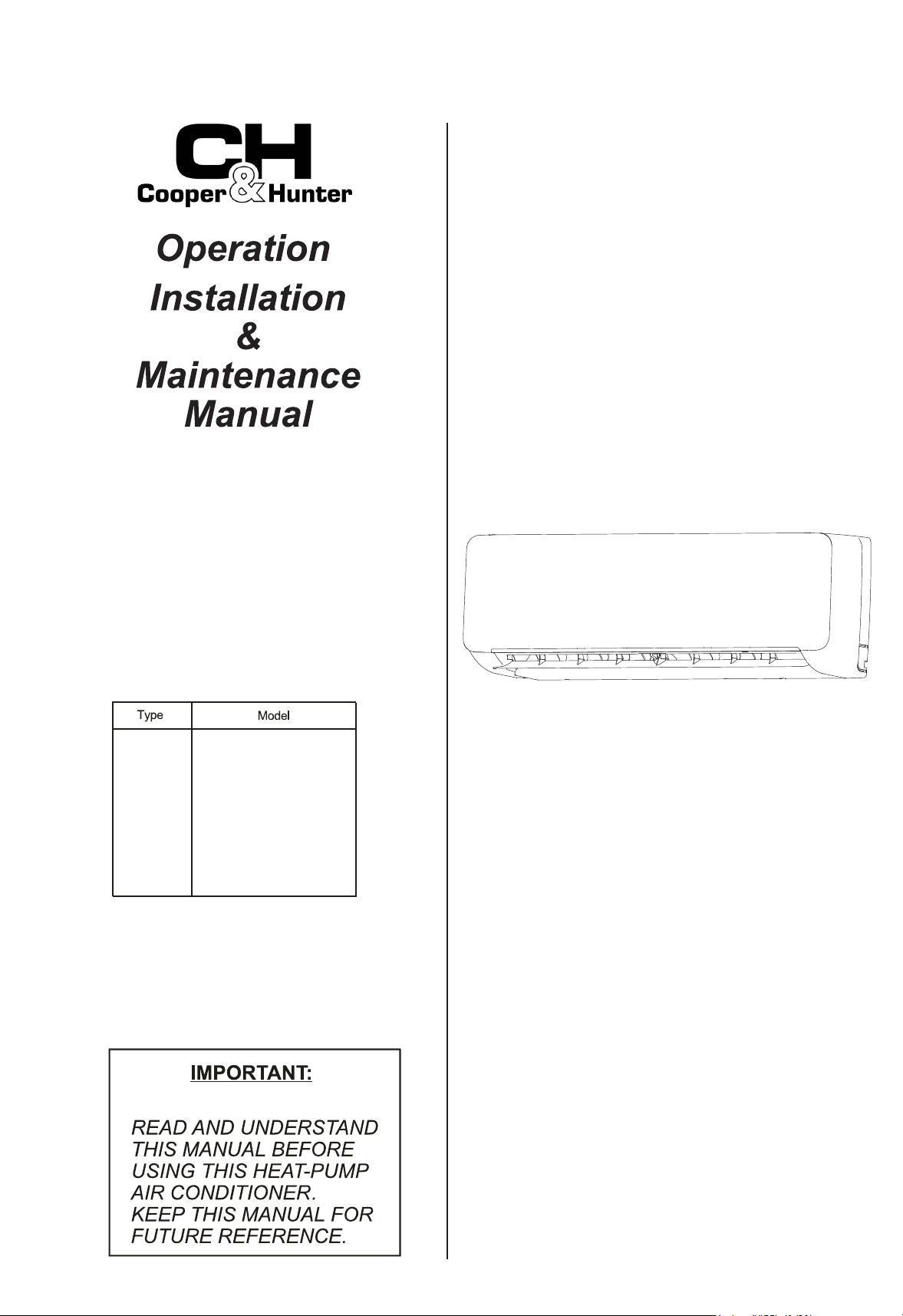
VRF INDOOR UNIT
Wall-
Mounted
Type
CHV-07WTU
CHV-09WTU
CHV-12WTU
CHV-15WTU
CHV-18WTU
CHV-24WTU
CHV-28WTU
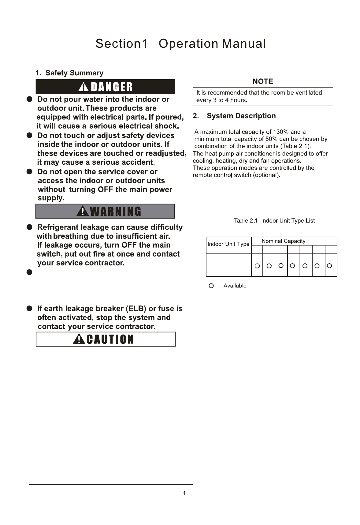
This product is a partial unit air conditioner, com
plying with partial unit requirements of this International
Standard, and must only be connected to other units that have been confirmed as complying to
corresponding partial unit requirements of this International Standard.
The model pictures in this manual are only for illustration. Please refer to the actual appearance.
The lowest moving parts should be mounted at least 8ft.(2.4m) above floor or grade level.
Refer to Installation & Maintenance Manual of outdoor unit for temperature operation range.
Immediate hazards which will result in severe personal injury or death.
Hazards or unsafe practices which could result in severe personal
injury or death.
Hazards or unsafe practices which could result in minor personal
injury or product or property damage.
's
's
IMPORTANT NOTICE
Correct Disposal of this product
This marking indicates that this product should not be disposed with other
household wastes. To prevent possible harm to the environment or human
health from uncontrolled waste disposal, recycle it responsibly to promote the
sustainable reuse of material resources. To return your used device, please use
the return and collection systems or contact the retailer where the product was
purchased. They can take this product for environmentally safe recycling.
The Company is committed to continuous product improvement. We reserve the right, therefore, to alter the
product information at any time and without prior announcement.
7
7
8
7
7
7
9
8
8
1
12
12
14
Section2 Installation & Maintenance Manual
Setting of Swing Louver
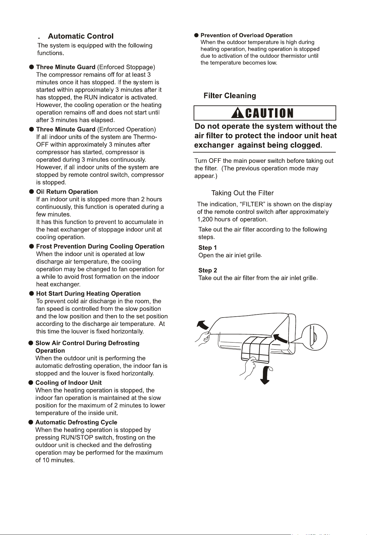
Filter Cleaning
TakingOuttheFilter
Cleaning the Filter
Reset ofFilterIndication
5
1
1
3
4
4
5
5
Identification of Parts
Remote Control Switch
Signal Receptor
19
15
1
1
18
18
19
19
Common
21
the Filter Indication Interval
10.4 Indoor Unit Address
22
10.3
10.2
10.1
1207 09
Wall-Mounted
Type
O
O
O
The appliance is not to be used by children
Children should be supervised that they
do not play with the appliance.
The appliance should not be installed in the
(kBtu/h)
or person with reduced physical, sensory
or mental capabilities, or lack of experience
and knowledge, unless they have been
given supervision or instruction concerning
use of the appliance by a person
responsible for their safety.
laundry.
O
If the supply cord is damaged, it must be
replaced by the manufacturer, its
service agent or qualified persons in
order to avoid a hazard.
15 18 24
Do not use any sprays such as
insecticide, lacquer, hair spray or other
flammable gases within approximately
() from the system.
28
2
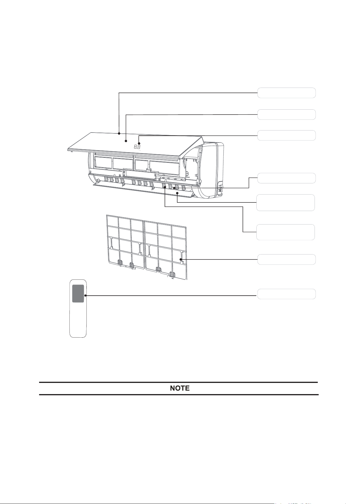
2.1 Identification of Parts
Fig.2.1 External Parts of the System
Air Intake
Air Outlet
V
ertical
Adjustment
Louver
Front Panel
Display Panel
Horizontal Adjustment
Louver
Air Filter
Remote Controller
Figures in the manual are only simple representation of the appliance.
It may not comply with the appearance of the air conditioner you purchased.
2
5
3
1
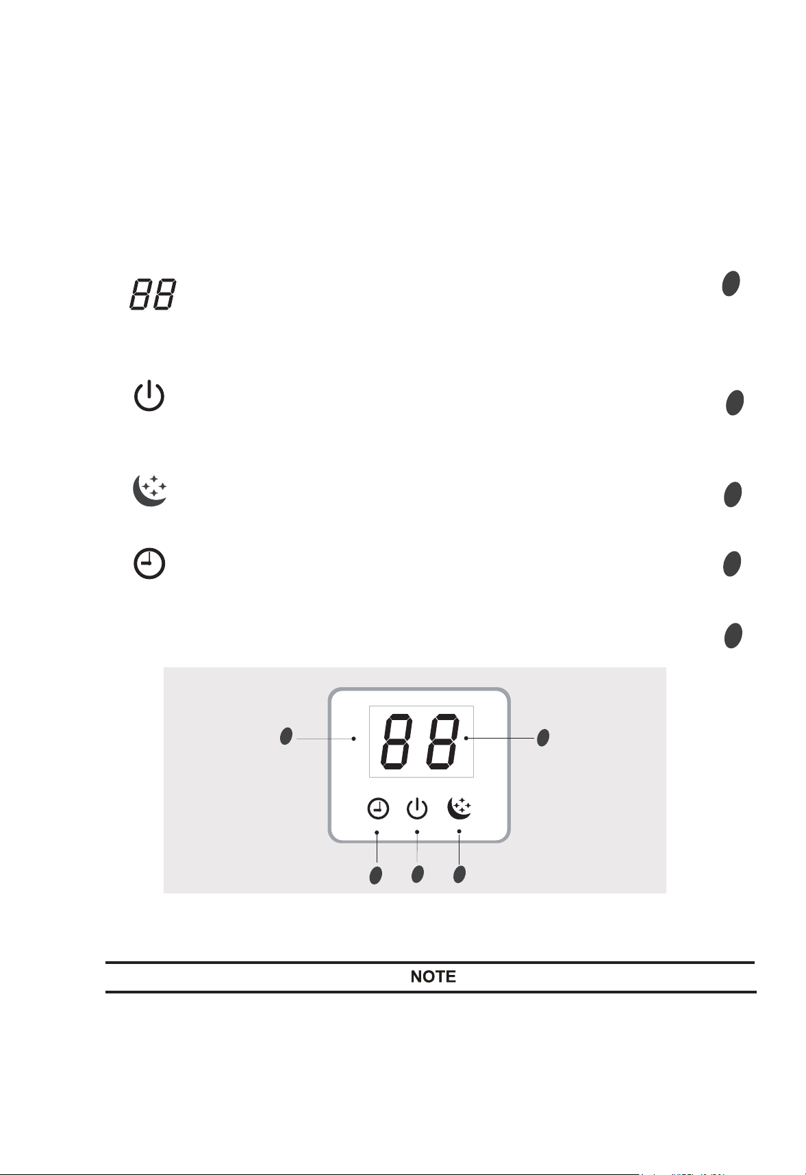
6LJQDO5HFHSWRU
Display introduction
4
Fig.4.1 Signal Receptor
To operate the room air conditioner, aim the remote controller to the signal receptor.
The remote controller will operate the air conditioner at a distance of up to 15(5)
when pointing at signal receptor of indoor unit.
Signal display lights for 10 seconds, when operate the wireless remote control switch.
Signal Receptor ..............................................................................
3
2
5
..............................................................................
4
Display set temperature.
It shows FC after 200 hours of usage as reminder to clean the filter.
After filter cleaning press the filter reset button located on the indoor
unit behind the frontpanel in order to reset the display.
Temperature indicator
Sleep indicator
It lights up in sleep mode.
Running indicator
.............................................................................
Timer indicator
It lights up during set time.
It lights up when the AC is running.
It flashes during defrosting.
1
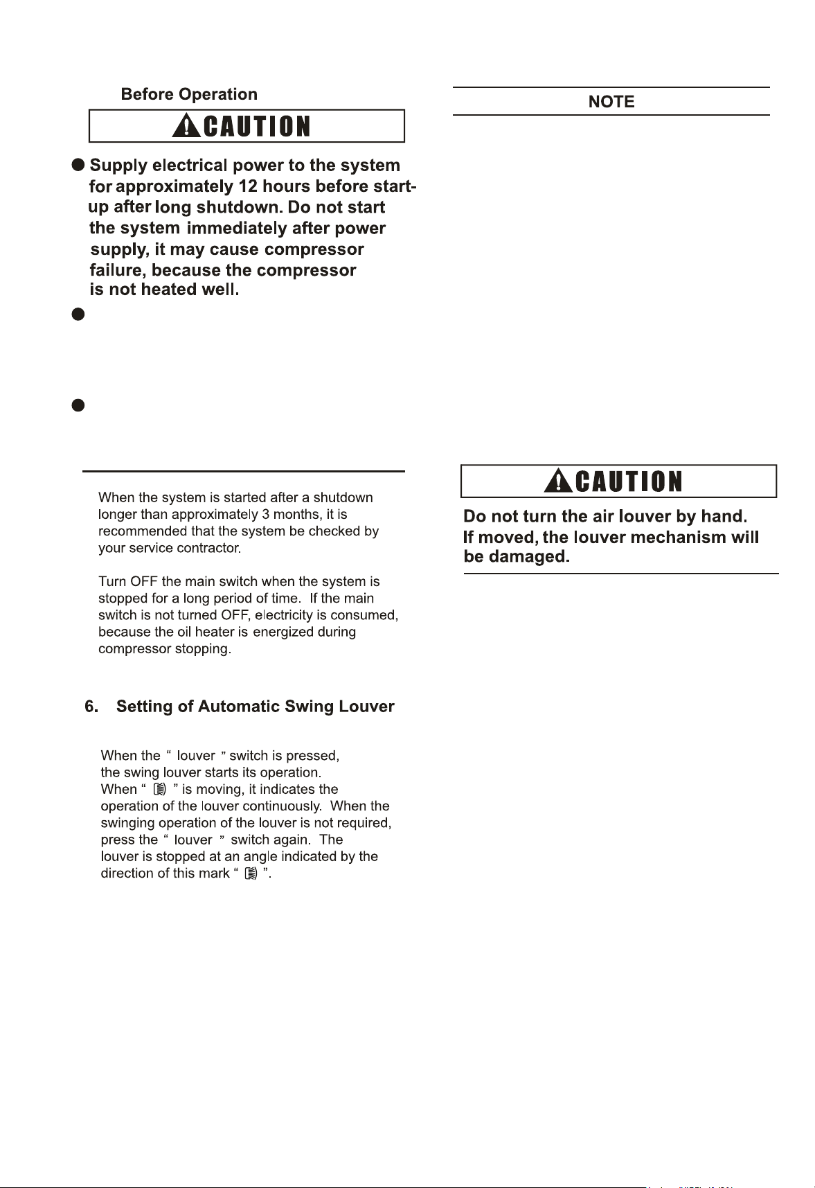
3. Remote
c
trol Switch
Refer to the control instruction manual for operation details.
4
5.
Make sure that the outdoor unit is not
covered with snow or ice. If covered,
remove it by using hot water
(approximately ).
If the water temperature is higher than
, it will cause damage to
plastic parts.
1.
2.
3.
There exists a time lag between the actual
angle of the louver and the liquid crystal
indication.
When the " " switch is pressed, the
louver will not stop immediately. The louver
will move one extra swing at the next.
Discharge air angle is fixed at horizontal
position during start-up of heating operation
and defrosting operation. When the outlet air
temperature reaches higher than approximately
30°C, swinging of louvers is started.
4. During the defrosting operation, fan stops
running.
7
8.
5
8.1
9
9.1
9.2
9.3
9.4
8.2
8.3
approximately.
d
“ RESET”
water.
7
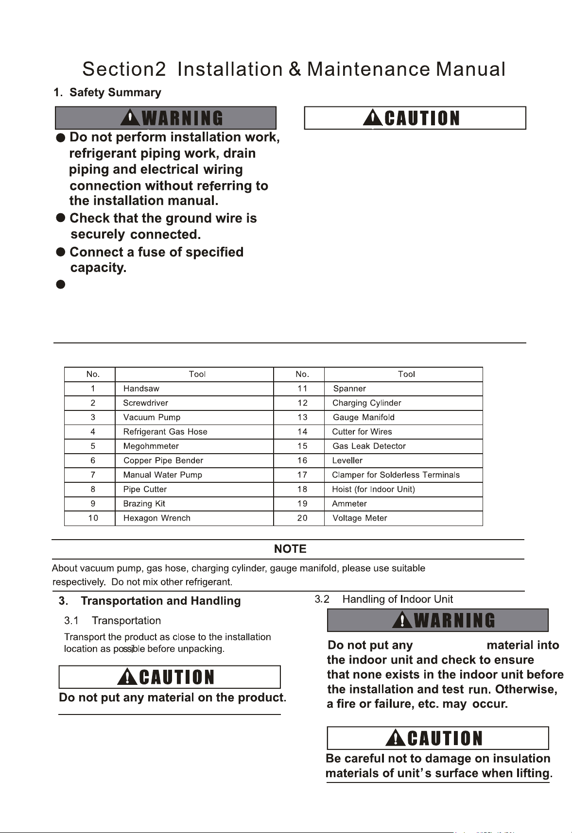
2. Necessary Tools and Instrument List for Installation
equipments for R410A
D
o not ins
tall the indoor unit,
outdoor unit, remote control
switch and cable within
approximately ()
from strong electromagnetic
wave radiators such as
medical equipment.
Users shall not change power
lines by themselves, please
be replaced by professional
maintenance staffs.
irrelevant
8
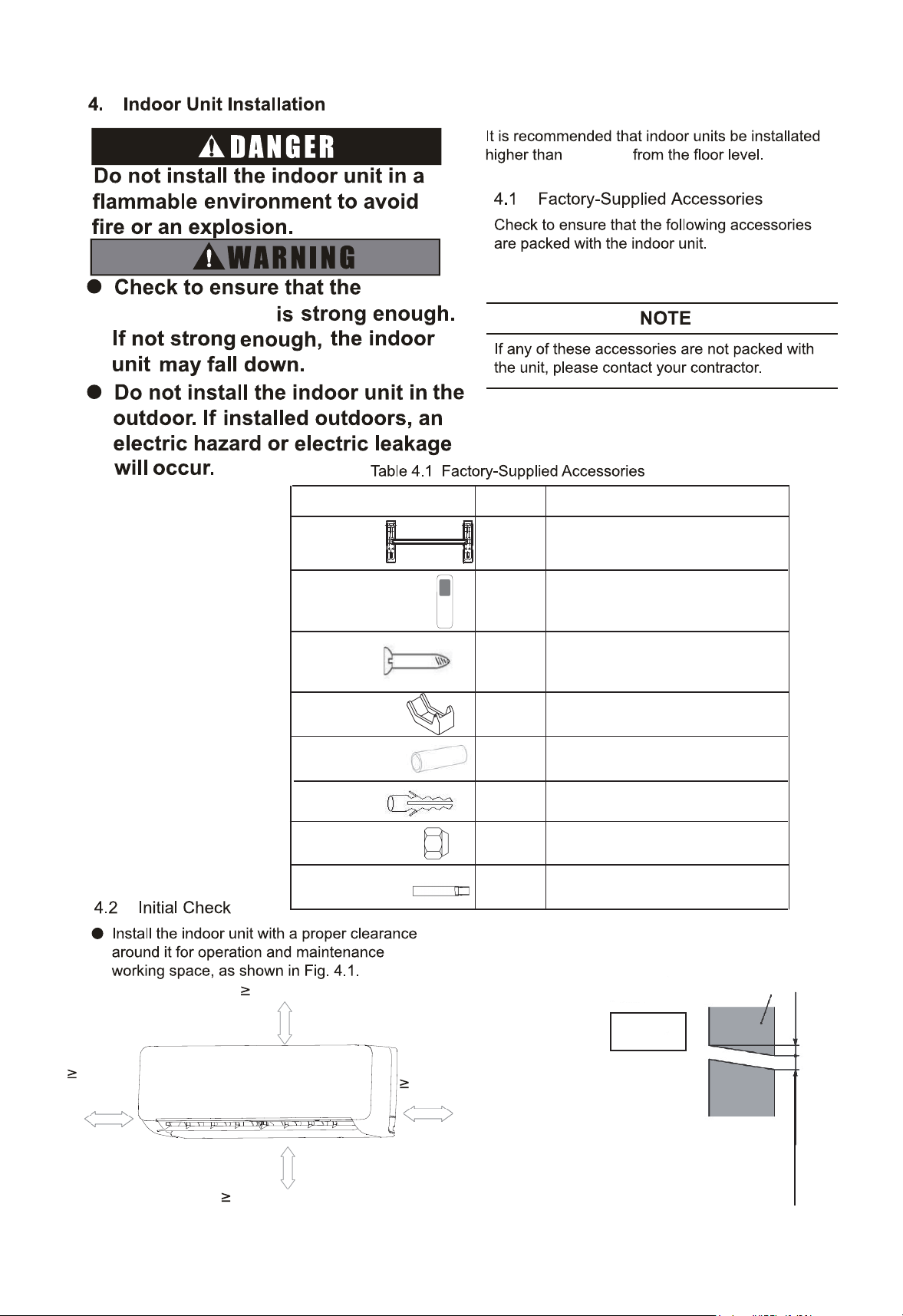
Accessory
Quantity
Purpose
Mounting
Bracket
Screw
Screw Cover
For Mounting Indoor Unit
For Mounting Bracket
Cover screw hole
9-8(1000)
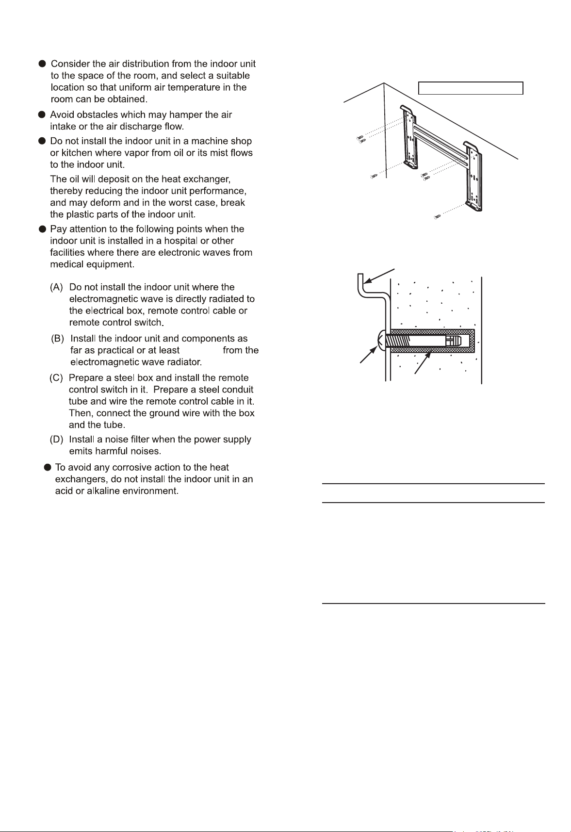
Fig. 4.1 Operation and Maintenance Space
Fig. 4.2 Hole for Piping in the Wall
For Refrigerant Pipe
Thermal
Insulation Pipe
6
1(
07-12)
3(15-28)
1
1
Wall
54(2) to
11(5)
Diameter of
2-91(5)
Hole for Piping
INDOOR
UNIT
8(24)
5-292(150)
-151(100)
unit:()
wall and
hanging
board
1
Wireless Remote
Control Switch
For Control the Indoor Unit
6
For Mounting Bracket
Plug
-151
(100)
unit:()
2
For Refrigerant Pipe
Refirgerant
Pipe Connection
For Piping Connection Kit (Gas)
(12(127)→8(95))
Cangeoe tue
107-12
9
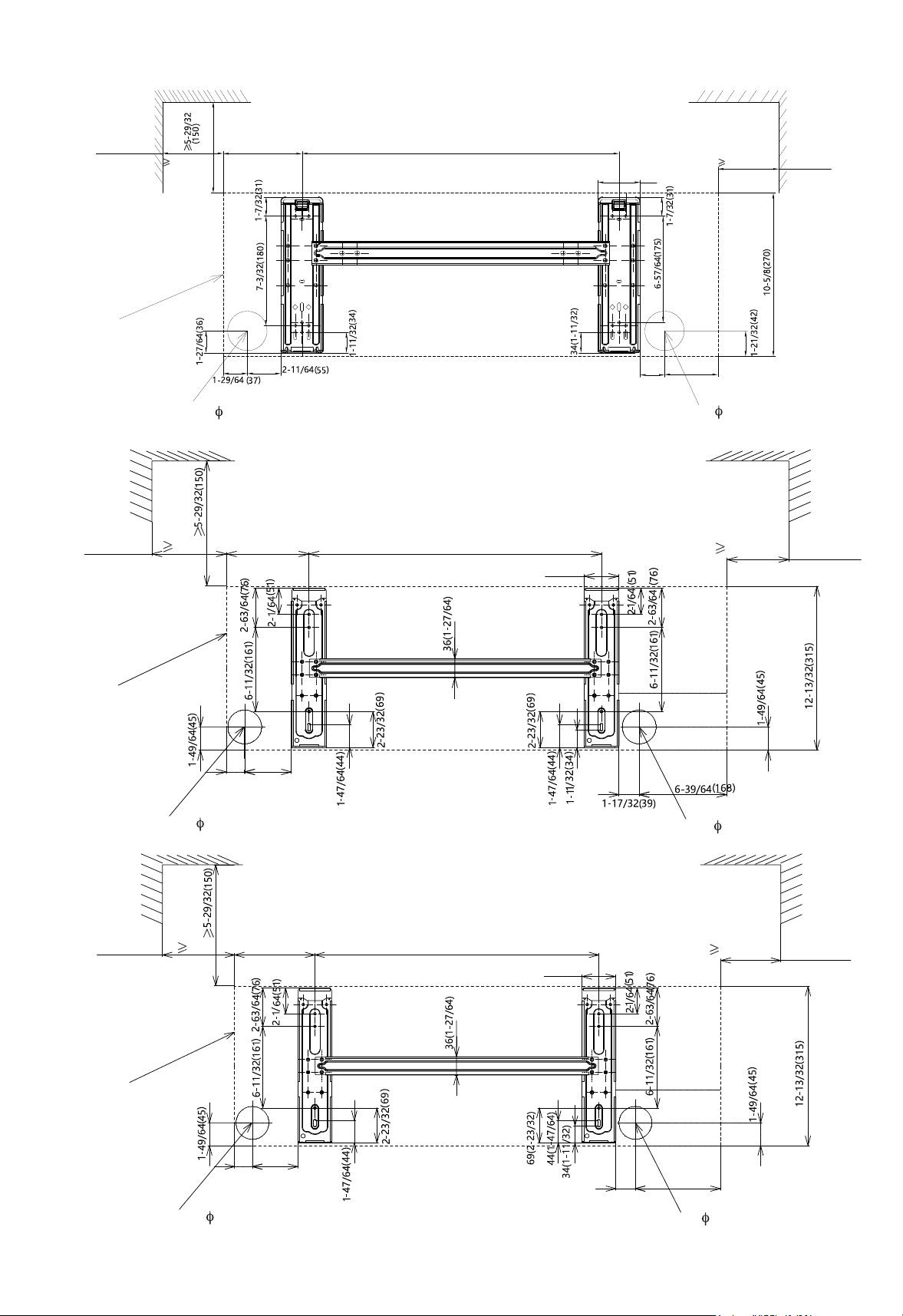
4.3 Installation
The dimensions of the mounting bracket and the
unit installation are indicated in Fig. 4.3.
4.3.1 Mounting Bracket onto Wall
When the mounting bracket is directly attached
to a wood wall or a concrete wall, check to ensure
of 0.45kip(2000N).
Mounting on a Concrete Wall or a Concrete Block
Wall: Attach the mounting bracket to the wall with
anchor bolts as shown in Fig. 4.4.
Mounting Bracket
Screw
Fig. 4.4 Mounting on Concrete Wall or
Concrete Block Wall
Fixing Screw for
Mounting Bracket
Mounting
Bracket
Utilize Six Screws.
NOTE
The mounting bracket should be installed
so that the side of drain piping connected
is slightly (about 18()) lower than
the other side, in order to avoid the
incorrect position of the drain discharge.
(Drain piping connection can be performed
both right side and left side of the unit.)
98()
Plug
Drill holes with
depth of 1-17/64in.
(32mm) in the wall
Servlce Space
Servlce Space
Servlce Space
Servlce Space
Servlce Space
Servlce Space
Outline of the Unit
Outline of the Unit
Outline of the Unit
Hole(2-91(5))
for Pipe and Wring
10
18~28
Fig.4.3 Mounting Bracket
15
07~12
unit:()
1-37/6440
4-49/64121
3-3/6490
1-7/3231
-151(100)
2-4(70)
20-54(522)
5(127)
-151(100)
-151(100)
22-2(51)
2-192()
-74(155)
-151(100)
Hole(2-91(5))
for Pipe and Wring
Hole(2-91(5))
for Pipe and Wring
Hole(2-91(5))
for Pipe and Wring
Hole(2-91(5))
for Pipe and Wring
Hole(2-91(5))
for Pipe and Wring
-151(100)
22-2(51)
11-2764(290)
-151(100)
2-192(66)
7-4164(194)
1-5764(48)
2-1364(56)
7-292(201)

One Each Side
11
Hook
Hook
4.3.2 Mounting the Indoor Units
Hook the indoor unit to the mounting bracket,
maintaining the indoor unit upright.
Fig 4.5 Mounting of the Indoor Units
4.3.3 Removing Flat Panel
In order to connect the refrigerant piping,
wiring and to check drain water flow, removing
the flat panel is needed. Perform these work
according to the following instructions. Pay
attention to the resin components not to scratch.
(1) Hold both sides of the flat panel and open it,
and pull the right arm toward the inner side.
Slightly close the flat panel and pull it, then
remove the flat panel.
Flat Panel
(2) Pay attention to the junction of grille
from each side, to prevent breaking off.
Fig 4.6 Slop angle of the Indoor Units
(1) The side of the drain pipe is
downward-sloping 2 degrees or 3 degrees
in the process of the unit installation.
(2) Check the drainage of the drain pan
through water overflow test.
Drain Piping
Mounting
Bracket
Catch
Slowly hold up and
press the unit downward.
Check to ensure that the unit is completely
hooked onto the mounting bracket. If not, it
may drop from the bracket, resulting in a
serious accident.
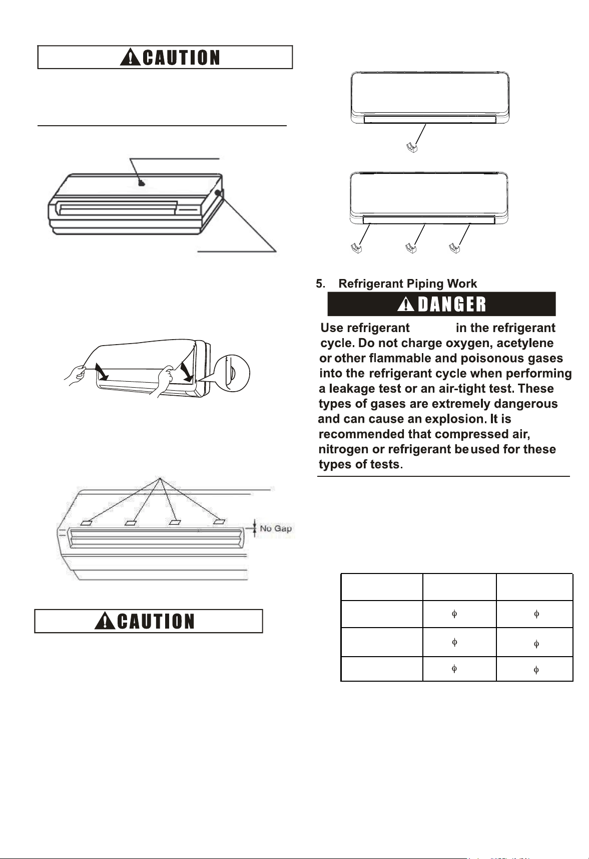
Flat Panel
Unit
Body
Any gap will lead to leak or frost.
unit:in.(mm)
Liquid pipe
Gas pipe
12
Stoppers
(2) There are four stoppers inside of the
flat panel. Check to ensure that there is no
gap between flat panel and unit body.
4.3.4 Install Flat Panel
(1) Press flat panel down, make the two joints of the
flat panel tightly fasten.
5.1 Piping Materials
(1) Prepare locally-supplied copper pipes.
(2) Select the piping size from the following table.
(3) Select clean copper pipes making sure there
is no dust and moisture inside the tubes. Before
connecting pipes, blow the inside of the pipes
with nitrogen or dry air to remove any dust or
foreign materials.
When removing flat panel, do not
apply strong forces by hitting, etc. It
may break the unit body.
R410A
07 ~
18 2
Model
(kBtu/h
5/8( 15.88)
3/8 9.53 1/4( 6.35)
(3) Put screws cover into the screw hole in the air outlet.
1/2( 12.7)
07-12
15-28
1/4( 6.35)
3/8 9.53
Insulation
For Left Side Piping
For Right Side Piping
Contour of the Unit
Bend
the
gas
pipe
at
the
flexible
pipe
part.
Insulation
Fig.5.2 Gas pipe
1
Contour of the Unit
For Right side Piping
For Left Side Piping
For Rear Side P i p i n g
For Rear Side
Piping
Small Cover
Right Side Cover
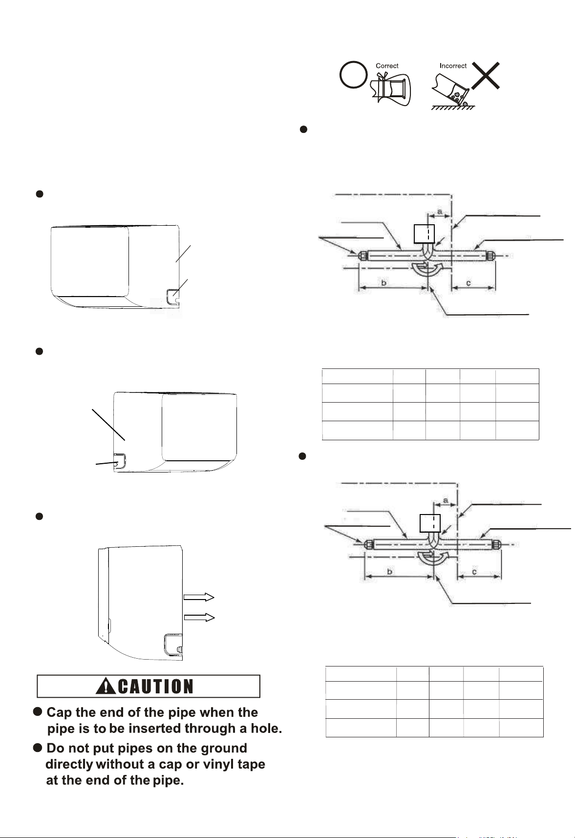
5.2 Piping Connection
(1) Position of piping connection is shown in
Figure 5.1 and 5.2.
(2) Piping Direction for the Indoor Unit: Three
directions of piping connection to the indoor
unit can be performed; to the rear side, the right
side and the left side of the unit respectively.
Therefore, most appropriate piping for a room can
be selected.
Right Side Piping
Take off the small cover from right side.
Take off the small cover from left side.
Rear Side Piping
Bend pipe backwards directly.
Small Cover
Cover
Left Side Piping
Left Side
d
d
unit:in.(mm)
a
c
Model(kBtu/h)
(78)
3-5/64
d
18 ~28
15
(76)
3
b
(396)
15-19/32
(431)
16-31/32
12-33/64
(355)
1331/32
(25R)
63/64R
(20R)
25/32R
(101)
3-31/32
07~12
(390)
15-23/64
(289)
11-3/8
(15R)
19/32R
Fig. 5.1 Liquid pipe
a
c
Model(kBtu/h)
64
2-33/64
unit:in.(mm)
d
18 ~ 28
15
60
2-23/64
b
437
17-13/64
464
18-17/64
373
14-11/16
404
15-29/32
10R
25/64R
20R
25/32R
86
3-25/64
07~12
456
17-61/64
370
14-9/16
10R
25/64R
he bed he ppes l
he ppe a he hea ehae sde
(318)
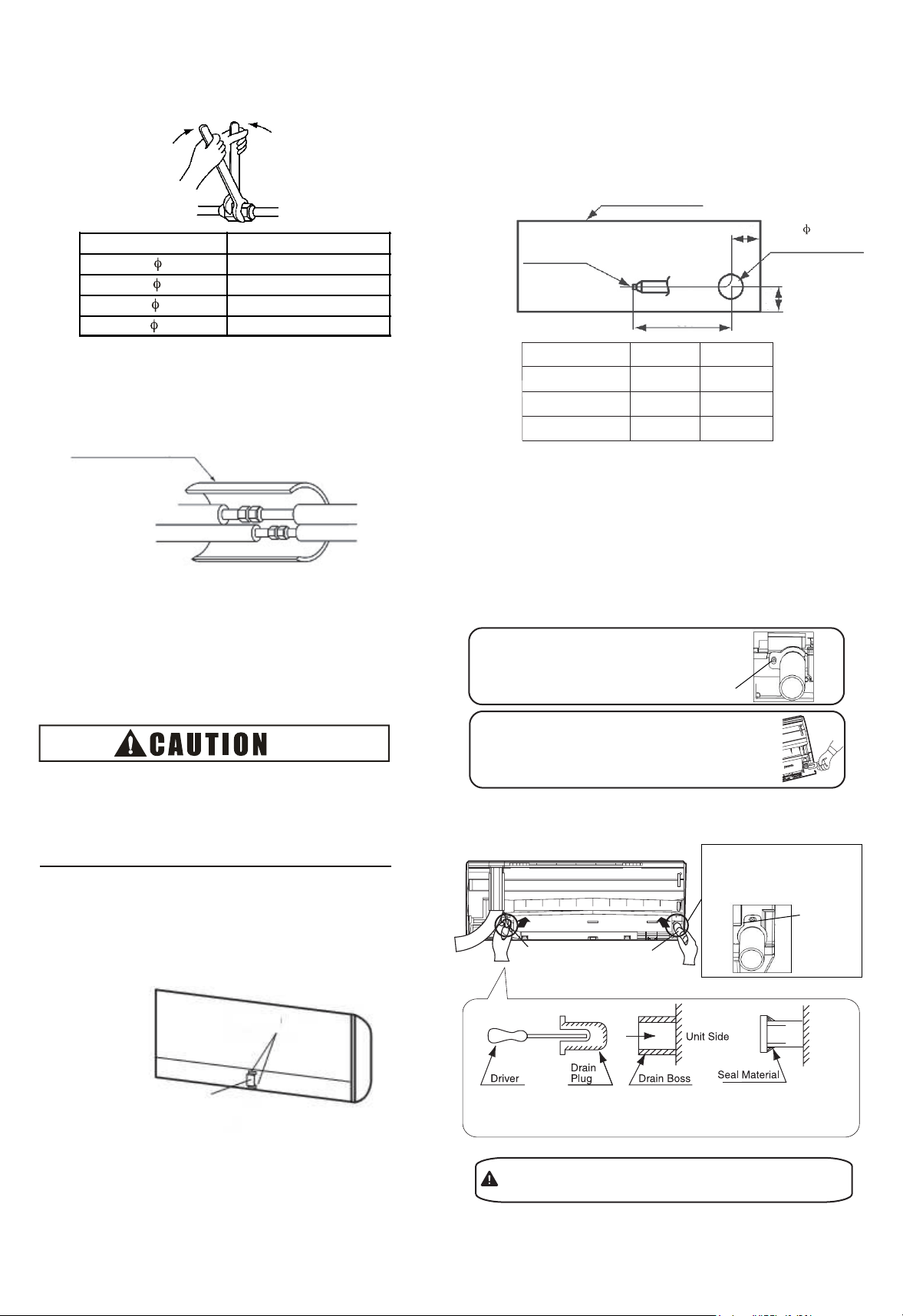
Fig.5.3 Tightening Work of Flare Nut
Fig. 5.4 Insulation on pipes
6. Drain Piping
14
148(20)
44(0)
Torque(())
(3) When tightening the flare nut, use two
spanners as shown in Fig. 5.3
(4) Insulate the refrigerant pipes as shown in
Fig. 5.4.
(5) Evacuation and refrigerant charging procedures
should be performed according to “Installation &
Maintenance Manual ” of the outdoor unit.
(2) when the left-side drain pipe connection is
performed, remove the drain plug of left-side,
and then attach this plug to the right-side
in order to change drain piping connection
from right-side to left-side.
An excess or a shortage of
main cause of
Charge the
refrigerant is the
correct refrigerant quantity.
trouble to the units.
45
Contour of the Unit
Drain Pipe
Connection
for Vinyl Pipe
(VP16)
65
Hole for
Rear Side Connection for
Wiring and Piping
(1) The standard direction of drain piping connection is
right side as viewed from the discharge grilles.
However, it can be performed from the left side or rear
side.
Pipe Diameter
295(40)
59(80)
a
b
Fig. 5.5
Stopper
Plate for Pipe
(6) Fix the plate of pipes (factory-supplied) as
shown in Fig. 5.5.
Thermal Insulation Pipe
(Accessory)
• Please use pliers to pull out the drain plug
CAUTION
Insufficient insert may
water leakage.
result in
Drain pipeDrain plug
screw
•
Remove the fixing screw for right-side
drain pipe and draw out the drain pipe
for left-side. (This is an easier way to
remove the drain cap).
from drain boss.
•
Insert the drain plug into the right-side drain boss and seal
the jointed part with water-proof chloride sealing material.
screw
Insert the drain pipe into
the left-side drain boss
and fix the screw.
(B) Insert the drain plug and drain pipe
(A) Draw out the drain plug and drain pipe
Fig. 6.1
a
Model(kBtu/h)
unit:()
18~28
15
195
7-43/64
168
6-39/64
600
23-5/8
b
Direction of Drain Piping
600
23-5/8
07~12
140
5-33/64
590
23-15/64
7
2-91
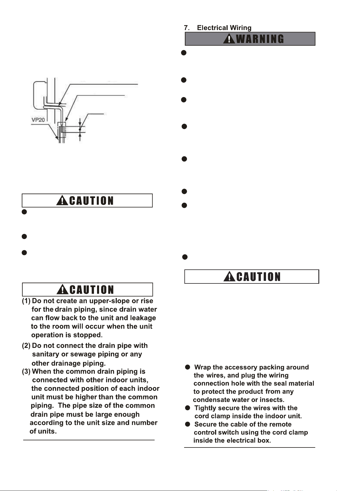
(4) Connect a drain piping as shown in Fig. 6
Provide a downward slope to
flow drain water smoothly
Use Adhesive Tape
15
(3) Provide a vinyl chloride pipe, VP20.
Use adhesive tape for connecting the drain pipe.
(5) Pour water into the drain pan and check to
ensure that water can flow smoothly.
Do not connect the drain pipes with
sanitary or sewage or any other
drainage pipe.
When installing the pipe, do not tie the drain
pipe and refrigerant pipe together.
Pay attention to the thickness of the
insulation when the left side piping is
performed. If it is too thick, piping can not be
installed in the unit.
O Tighten screws according to the
following
torque.
.2.
Fig. 6 Connection of Drain Piping
.2
1424
M3.5: ()
M4: ()
M5: ()
M6: ()
M8: ()
M10: ()
ft·lbs
Turn OFF the main power switches to the
indoor unit and outdoor unit before
electrical wiring or periodical check, and
wait for at least 10 minutes.
Check to ensure the indoor and outdoor
fans have stopped before electrical wiring
or periodical check.
Protect the wires, drain pipes, electrical
parts, etc. from rats or other small animals.
If not protected, rats may gnaw at
unprotected parts, which may lead to a fire.
Avoid the contact of wires with the
refrigerant piping, sheet metal edges and
electrical components in unit. Otherwise,
the wires may get damaged or even cause
a fire.
Use ELB(earth leakage breaker) with
medium sensing rate (ELB with action time
being equal to 0.1 seconds or less). Failing
to do so may result in electric shock or a
fire.
The wires must be firmly secured. External
force applied to terminals may cause a fire.
It is forbidden to connect a plurality of
power lines into one power terminal block.
At the indoor unit side of air conditioner,
power wiring can be extended through a
power distribution box. Be sure to calculate
the wiring capacity carefully, since
excessively low wiring capacity may
frequently cause fire.
Do not start the system before all check
points are thoroughly checked.
1
7.1 General Check
(1) Make sure that the field-supplied electrical
components (main power switches, circuit breakers,
wires, conduit connectors and wire terminals) have
been properly selected according to the electrical
datagiven in “Technical CatalogⅠ” . Make sure that
thecomponents comply with National Electrical Code
(NEC).
(2) Use shielded twist pair cable for transmission
wiring between outdoor unit and indoor unit, remote
controller wiring between indoor units and remote
control switch.
(3) Check to ensure that the power supply voltage is
within ±10% of the rated voltage.
(4) Check the capacity of the electrical wires.
If the power source capacity is too low, the system
cannot be started due to the voltage drop.
(5) Check to ensure that the earth wire is connected.
(6) Power Source Main Switch.
Install a multi-pole main switch with a space of94
(5) or more between each phase.
7.27.2 Electrical W
iring Connection
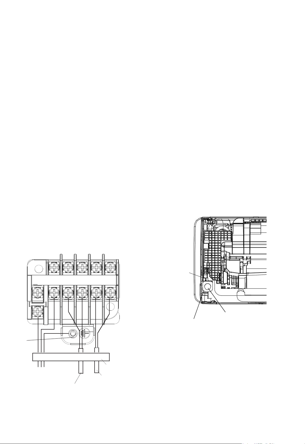
The electrical wiring connection for the indoor unit
is shown in Fig. 7.1.
(1) Unscrew and remove the conduit mount plate
from the machine base. Fix a conduit for power
supply wiring to the plate with a lock nut and reattach
them at original position.
(2) Connect the wires of an optional remote control
switch to A, B terminals of the terminal board inside
the electrical box through the connecting hole in the
cabinet.
(3) Connect the wires between the indoor unit and
the outdoor unit to1, 2terminals of the terminal
boardinside the electrical box through the
connecting holein the cabinet.
(4) Connect power supply wires to L1, L2 and
connect earth wire to the earth. Please connect to the
power circuit with a ELB.
(5) Check to ensure that the terminal specification is
applied to the screw (M3.5 for power supply and
operating line) of the terminal box.
(6) Fix all the wires securely with cord clamp.
Remote Controller Wiring
Indoor and Outdoor
Transmission Wiring
Fig.7.1 Wiring Connection
Power Supply
08/3060Hz
Earth Wiring
Screw
Cord Clamp(All wirings are
fixed with cord clamp)
L1 L2
1 2 A B
Hole for Power Wiring
Conduit Mounting Plate
For the minimum size of field-supplied power
cord, please refer to Section 10.1.
Screw
C
T
17
0
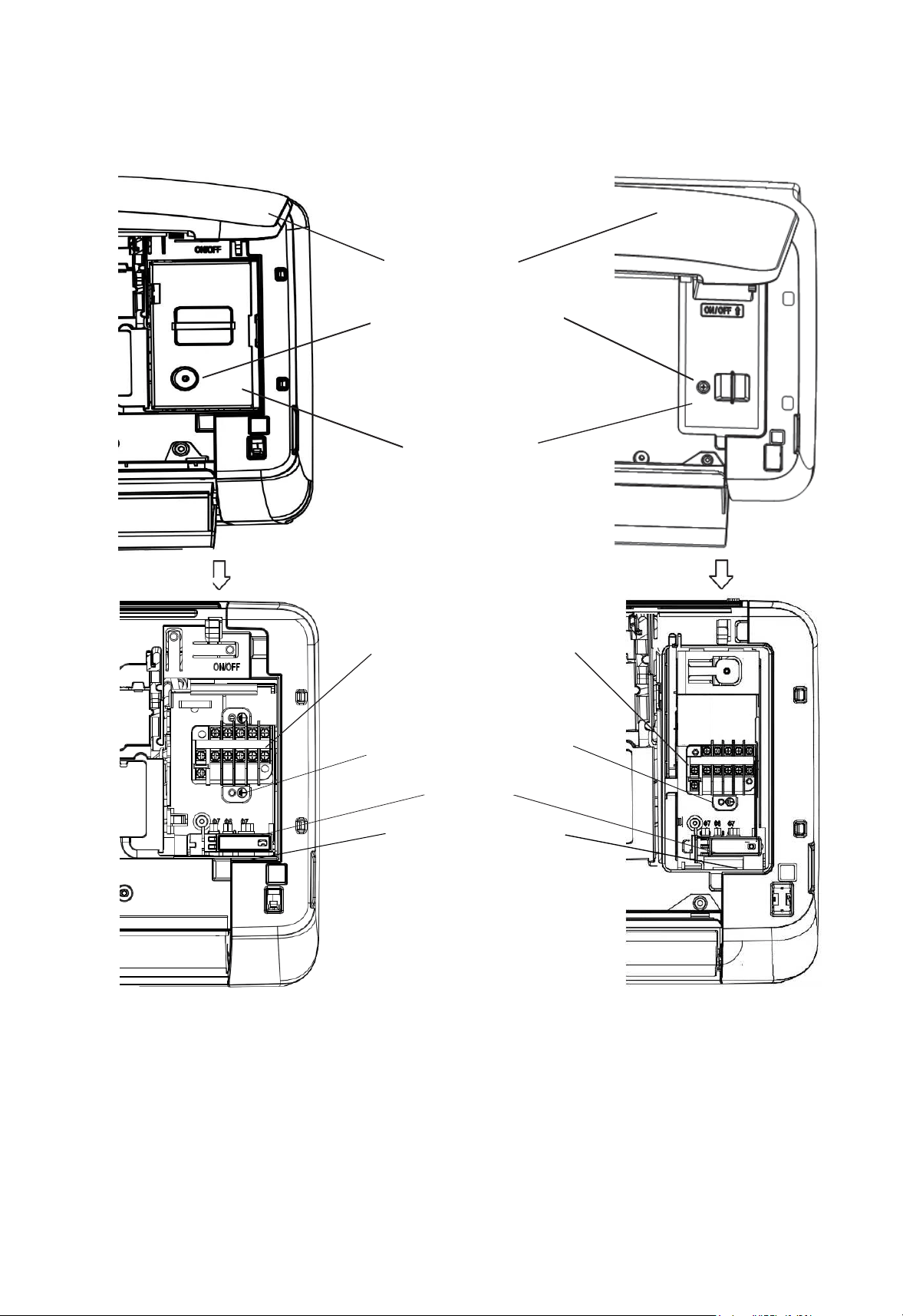
Open the flat panel
Remove the fixing screw
for the electrical box cover
Electrical box cover
TB1 for Power Supply(L1 L2)
and Transmission wiring(1 2)
and Remote control switch(A B)
TP(terminal plate) for Earth wire
Cord clamp
Pass the wires through the
hole in the cabinet to the
rear side
18
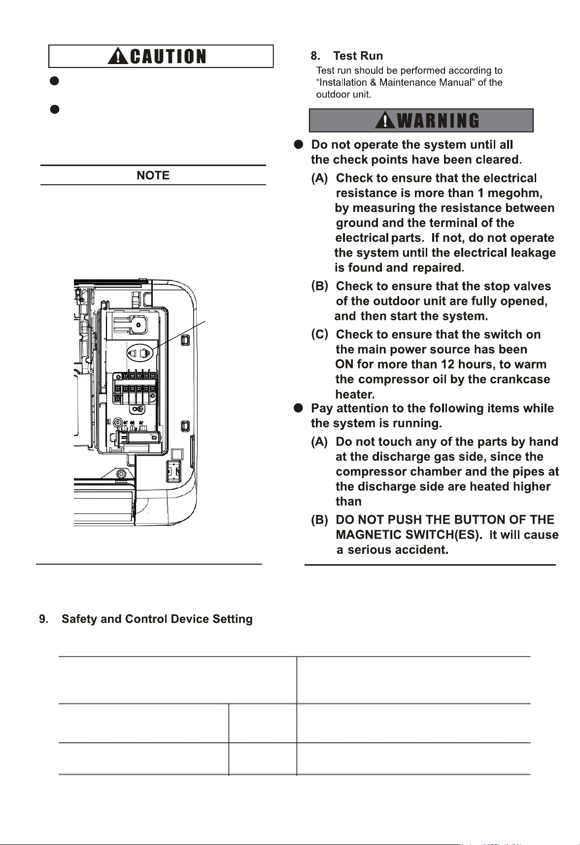
Fig.7.2 Connection description for signal receptor
Disconnect the wire
of signal receptor
ELB must be connectedto the power
circuit.If not, it may pose a danger.
Apply the specified screw for terminal
board and fasten the screw firmly.
Wired Remote Control Switch and Wireless Remote
Control Switch can not be used simultaneously.If
Wired Remote Control Switch is connected, disconnect
the wire of signal receptor in the electrical box. As
shown in the Fig.7.2.
Cut-Out
Cut-In
Freeze Protection
Thermostat
A
5
320
5814
Model
Indoor Unit
07~28
°FC
°FC
CC
C
19
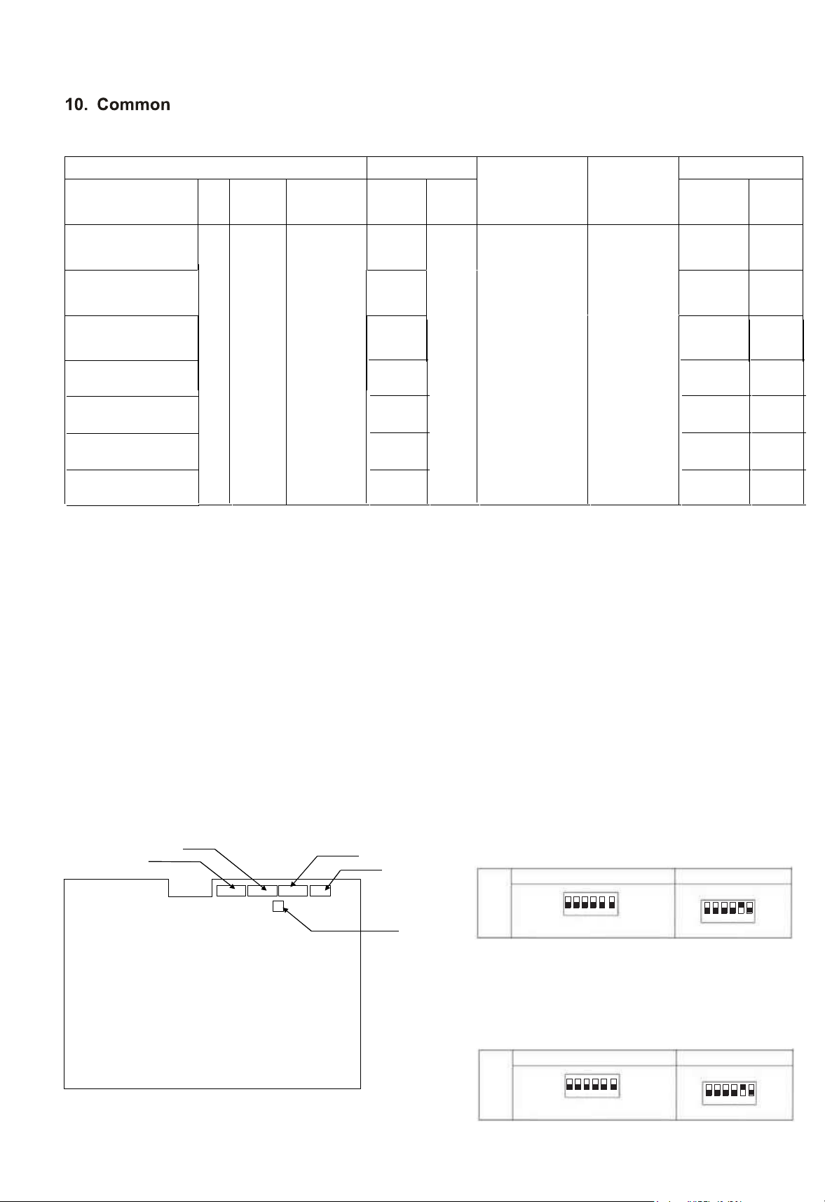
10.1 Field Minimum Wire Sizes for Power Souce
Units Power supply
Power supply
wiring size
Communica
tion Cable
Size
Fan motor
Model Hz Volts
Voltage
range
MCA MOP kW FLA
60
208/
230V
Max.253V
Min.187V
0.45
Wiring size
and length
must
comply with
local codes.
AWG18
*1
(0.82mm
2
)
0.0
25
0.11
CHV-07WTU
0.
56
0.035
0.16
CHV-15WTU
1.02
0.035
0.15
CHV-18WTU
NOTES:
MCA: Min. Circuit Amps (A); MOP: Max. Overcurrent Protective Device (A)
kW: Fan Motor Rated Output (kW); FLA: Full Load Amps (A)
(1) Use a shielded cable for the transmitting circuit and connect it to ground.
(2) Field wiring shall be in conformity to local laws and regulations, and all wiring operations must be performed
qualified professionals.
(3) Once the power cord is damaged, the dealer or the professionals from designated maintenance departmen
must be contacted in a timely manner for repair and replacement.
15
DSW3
DSW6
DSW4
DSW5
DSW7
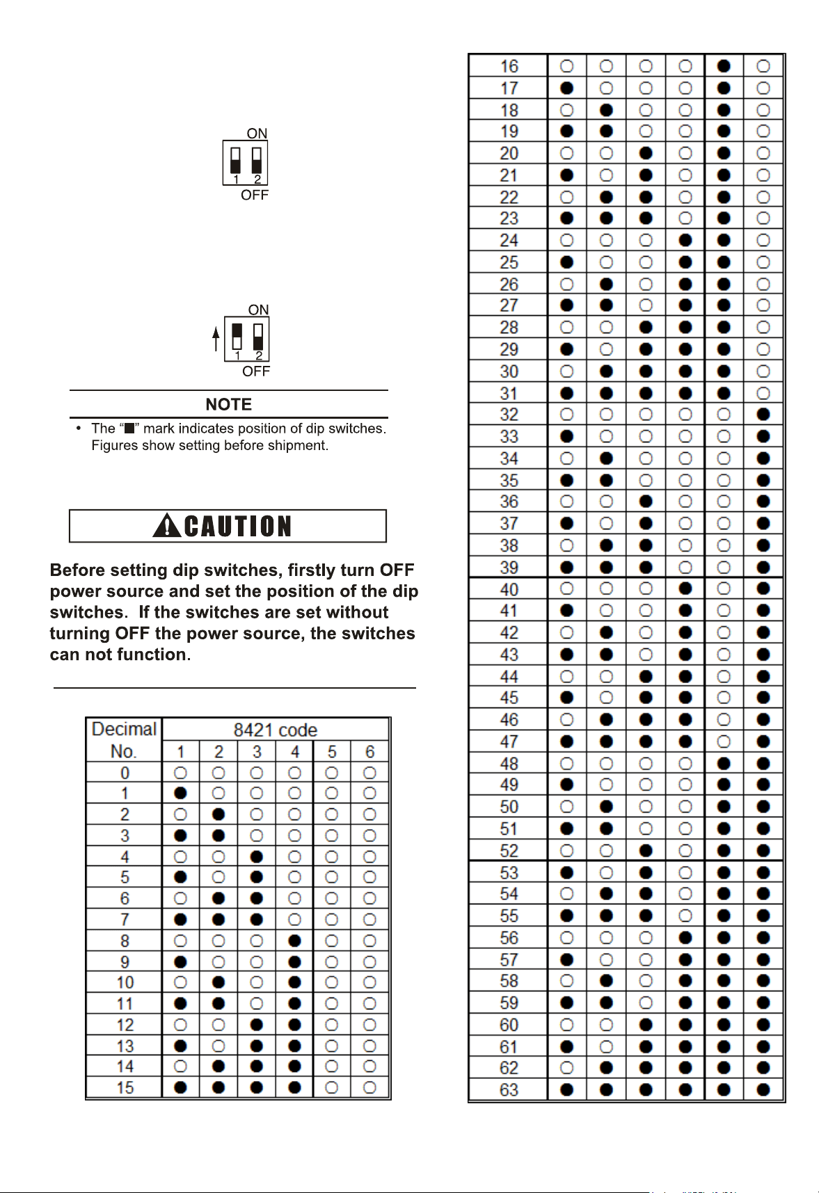
10.2 Setting of Dip Switches
(1)1) DIP switch must be set with power sources of
indoor and outdoor units in OFF state. Otherwise,
the settings are invalid.
(2)2) The DIP switches are located as shown in
figure below.
(3) 5 dip switches are arranged on the PCB of indoor
unit, and must be set based on the following
instructions before test run. The system shall not
be started before the completion of dip switch
setup.
(a) Address of indoor units (DSW6): All indoor
units must be numbered in sequence based on
the diagram below. Outdoor units must be
numbered from "0".
Setting
Method
DSW6 (Setting 0~63)
Ex.) Set address No.16
ON
OFF
Note: 8421 coding method
DSW6
ON
OFF
No.5 isON
1 234
56
1
23456
(b) Refrigeration system cycle No. ( DSW5)
is required to be set. All are set to OFF
before shipment.
0.0
25
0.11
0.0
25
0.11
0.035
0.15
0.035
0.15
CHV-09WTU
CHV-12WTU
CHV-24WTU
CHV-28WTU
0.45
0.53
0.
56
0.94
Setting
Method
DSW5 (Setting 0~63)
Ex.) Set address No.16
ON
OFF
Note: 8421 coding method
DSW5
ON
OFF
No.5 isON
1 234
56
1
23456
2
20
(
4) Fuse Recover(DSW7)
No setting is required.
Setting position before shipment is at OFF.
Once strong current is accidentally connected
to Terminals 1 and 2 of TB, the PCB fuse will
be blown. In such a case, it's essential to
c
o
r
r
e
c
t
t
h
e
w
iring and then to set switch No. 1
to ON position.
21
10.3 Setting the Filter Indication Interval
The FILTER indication interval on the remote control switch can be set at every 100,
1,200 or 2,500 hours (factory setting: 1200 hours). If 100, 1,200 or 2,500 hours' interval
is required, follow the instructions below.
FILTER Indication Interval
Approx.
100 hr.
Approx.
Approx.
1,200
hr.
Approx.
2,500 hr.
No.
Indication
b4 01
b4 00(*)
b4 02
b4
03
b4
04
(*): Standard
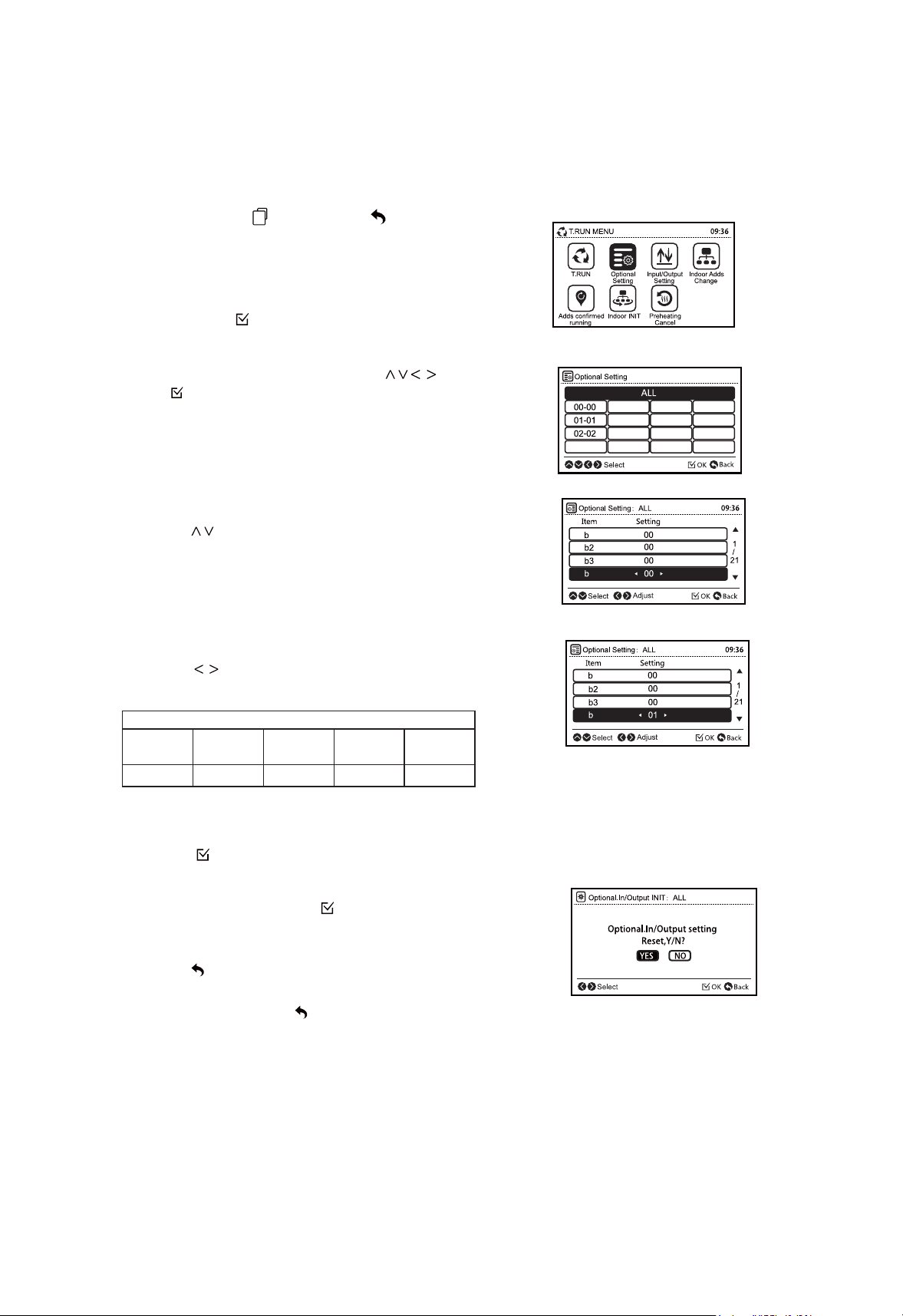
(1)Press and hold
" "
(menu) and
" "
(return)
simultaneously for at least 3 seconds during the normal
mode (when unit is not operated).The test run menu will
be displayed.
4
1
4
1
(2) Select " Optional Setting " from the test run
menu pressing " ".
" and (3)Select the indoor unit by pressing "
press " ".
(This screen is NOT displayed when the number of
indoor unit connected with the remote control switch
is 1(one). In this case, (4) will be displayed.)
(4) Press " " and select the item.
(5) Press " " and change the setting.
(6) Press " " so that the confirmation screen will be
displayed.
(7) Select " Yes " and press " ". The test run menu will
be displayed after the setting is confirmed. If " NO" is
pressed, the screen will return to (4).
(8) Press " " (return) on the test run menu to return
to the normal mode.
To set other units, press " " (return) at (4) (5) so that the
screen will return to (3). ( If the number of indoor unit
connected with the remote control switch is 1 (one), the
screen will return to (1).)
1,200 hr.
10.4 Indoor Unit Address
NOTE
22
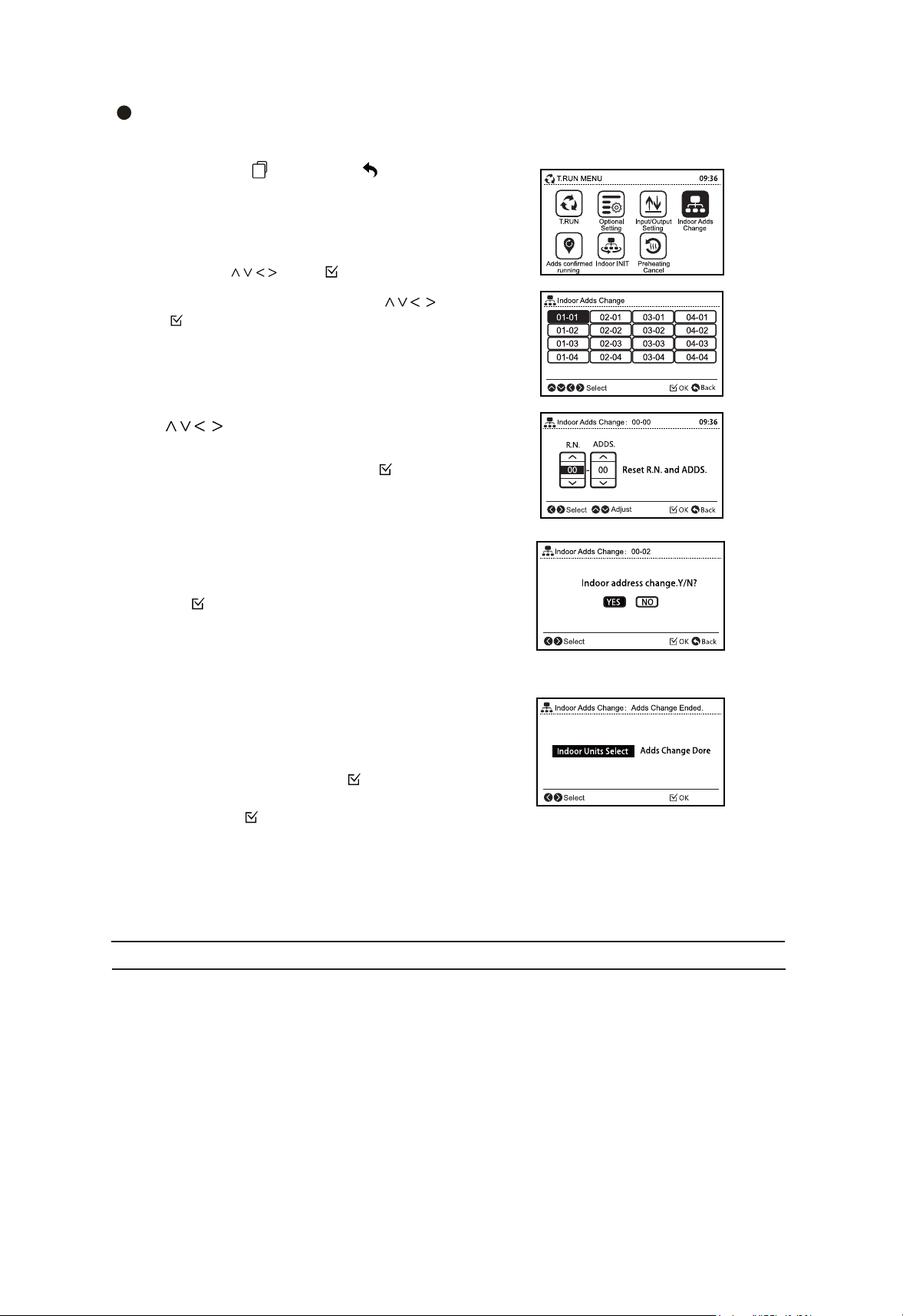
Indoor Unit Address Change
This function changes the address (refrigerant cycle number and indoor unit number) of indoor units.
(1) Press and hold (menu) and (return)
simultaneously for at least 3 seconds during the normal
mode (when unit is not operated).The test run menu will
be displayed.
" "
" "
(2) Select "Indoor Adds Change" from the test run
menu pressing " " and " ".
" and (3)Select the indoor unit by pressing "
press " ".
*Indoor units which are not supporting " Indoor Adds
Change " function can not be selected.
(4) Determine the new indoor unit address.
Press " " to switch the refrigerant cycle
number and address in range of 00-63.
To display confirmation screen press " ".
* " R.N No.99 " is used temporarily address only when all the
cycle numbers and unit numbers are in use (occupied).
If " R.N No.99" is used temporarily, the address must be
changed within the standard range of 00-63.
(5) The confirmation screen will be displayed. Select " Yes"
and press " " to stard address change process. Result will
be displayed in seconds. If " No" is pressed, the screen will
go to (6).
*When the process successfully completes, " Adds
Change Ended " will be displayed.
Otherwise the process has been failed. Check the setting
and contents again.
(6) To change the address for another indoor unit, select
" Indoor Units Select " and press " " ,the screen will
return to (3). To finish this function select " Adds Change
Done " and press " ".
*If " Indoor Adds Change" is successfully completed, connection
check will be started automatically.
(7) Turn OFF the power supply of the indoor units for 3-5 minutes. Wait until the remote
control switches display turn off, and turn ON the power supply of indoor units again.
" Indoor Adds Change " is not available when the control of 2 remote control switches (main and
sub) are used.
Do not operate from the central controlling devices while " Ind
oor Adds Change" is performed by
the remote control switch.
This function should not be used if there is a Central Control in the H-NET.

2
Address Check Operation
This function is used to check the relation between the indoor unit and I.U. address. This
operation is effective when multiple indoor units are connected to the remote control switch and
address of the certain unit is unknown.
(1)
" "
Press and hold (menu) and (return)
" "
simultaneously for at least 3 seconds during the normal
mode (when unit is not operating).The test run menu will
be displayed.
(2) Select " Adds confirmed running" from the test run
menu pressing " " and " ".
(3) Select the indoor unit by pressing " ".
(4) To start operation of the indoor unit selected in (3)
press " " (run/stop). To return to (3) screen press " " (run/
stop) while indoor units is operated.
*Repeat (3)-(4) until desired indoor unit address is confirmed.
(5) To return to the test run menu press " " (return) while
indoor unit is not operated.
Indoor Unit Address Initialization
This function initializes the indoor unit address that has been changed by " Indoor Adds
Change " function or set by the automatic address a llocation. Initializing the address will
be changed to the dip switch setting.
(1)Press and hold menu) and
(return)
simultaneously for at least 3 seconds during the normal
mode (when unit is not operated) .The test run menu will
be displayed.
" "
" "
(2) Select "Indoor INIT" from the test run menu pressing
" " and " ".
(3) Select the" Reset Indoor Adds "by pressing " "
and press " ".
(4) Select the indoor unit by pressing " " and
press " " . The confirmation screen will be displayed.
*Indoor units which are not supporting " Reset
Indoor Adds" function can not be selected.
The address of indoor unit that does not support "
Reset Indoor Adds" function will not be initialized
even when "All" is specificated.
(5) Select "Yes" and press " " to start the address
initialization process.
*If the address initialization is successfully completed,
connection check will be started automatically.

08.2022 V01
The Company is committed to continuous product improvement. We reserve the right, therefore, to alter the product information at any time and without prior
announcement.