
DXCM201
Single Stage, Belt Drive, Electric Air Compressor
Compresseurs d’air électriques à un étage à entraînement par courroie
Compresores eléctricos de aire, de una sola etapa y accionamiento por correa
INSTRUCTION MANUAL
GUIDE D'UTILISATION
MANUAL DE INSTRUCCIONES
INSTRUCTIVO DE OPERACIÓN, CENTROS DE SERVICIO Y
PÓLIZA DE GARANTÍA. ADVERNTENCIA: LÉASE ESTE
INSTRUCTIVO ANTES DE USAR EL PRODUCTO.
If you have questions or comments, contact us.
Pour toute question ou tout commentaire, nous contacter.
Si tiene dudas o comentarios, contáctenos.
1-888-895-4549 • www.DEWALT.com
MAT Industries, LLC, Long Grove, IL 60047
(APRIL 19) Part No. E112138 DXCM201 Copyright © 2019 DEWALT
2
English
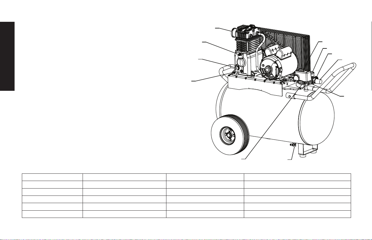
Air Compressor
A. Pump Air Intake Filter
B. Auto(-)/Off(O) Switch
C. Air Tank Pressure Gauge
D. Regulated Pressure Gauge
E. Pressure Regulator
F. Air Outlet
G. Safety Valve
H. Air Tank Drain Valve
I. Pump Oil Fill Plug
J. Pump Oil Drain Plug
K. Pump Oil Sight Glass
L. Quick Connect
Pump Specifications
2 Cylinder
Single Stage
Oil Lubricated
Cast iron crankcase, cylinder, and aluminum head
Weight: 27.0 lbs (12.2 kg.)
Oil Capacity: 16 fl. oz. (473 mL)
Specifications
MODEL DXCM201
APPROX. CUT OUT PRESSURE
200 PSI
WEIGHT 137 lbs. (62.1 kg)
AIR DELIVERY
6.2 SCFM @ 90 PSI
HEIGHT 32"
TANK FILL TIME
5.5 MINUTES
WIDTH 22"
INPUT
120V, 60HZ, SINGLE PHASE AC ONLY, 15 AMPS
LENGTH 33" WITHOUT FRONT HANDLE
MIN. BRANCH CIRCUIT REQ
20 AMPS
AIR TANK CAPACITY
20 GALLONS (75.7 L)
FUSE TYPE
TIME DELAY
A
B
C
D
E
F/L
G
H
I
J
K
3
English
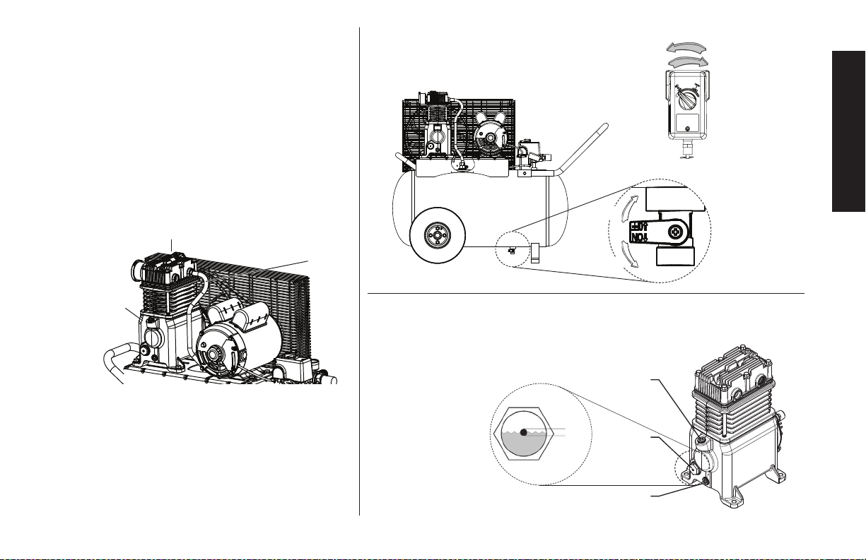
Fig. 2
OPEN
CLOSE
OFF
AUTO
Fig. 3
FULL
ADD
J = Oil drain plug
K = Oil level sight glass
I = Oil fill plug
J
K
I
Fig. 1 Hot Surfaces
COMPRESSOR CYLINDER & HEAD
PUMP
CRANKCASE
OUTLET
TUBE

4
English
Definitions: Safety Guidelines
The definitions below describe the level of severity
for each signal word. Please read the manual and pay atten-
tion to these symbols.
DANGER: Indicates an imminently hazardous situation
which, if not avoided, will result in death or serious injury.
WARNING: Indicates a potentially hazardous situation
which, if not avoided, could result in death or serious injury.
CAUTION: Indicates a potentially hazardous situation which,
if not avoided, may result in minor or moderate injury.
NOTICE: Indicates a practice not related to personal injury
which, if not avoided, may result in property damage.
IF YOU HAVE ANY QUESTIONS OR COMMENTS ABOUT
THIS OR ANY D
E
WALT TOOL, CALL US TOLL FREE AT:
1-888-895-4549
Important Safety Instructions
WARNING: Do not operate this unit until you read this instruction
manual for safety, operation and maintenance instructions.
WARNING: CONTAINS LEAD. May be harmful if eaten or chewed.
May generate dust containing lead. Wash hands after use. Keep out
of reach of children.
WARNING: This product can expose you to chemicals including
lead, which is known to the State of California to cause cancer and
birth defects or other reproductive harm. For more information go
to www.P65Warnings.ca.gov.

5
English
• Unattended operation of this
product could result in per-
sonal injury or property dam-
age. To reduce the risk of
fire, do not allow the com-
pressor to operator unat-
tended
• Always remain in attendance
with the product when it is
operating.
• Always turn off and unplug
unit when not in use.
DANGER: RISK TO BREATHING (ASPHYXIATION)
WHAT CAN HAPPEN HOW TO PREVENT IT
• The compressed air directly
from your compressor is not
safe for breathing. The air
stream may contain carbon
monoxide, toxic vapors,
or solid particles from the
air tank. Breathing these
contaminants can cause
serious injury or death.
• Never use air obtained directly
from the compressor to supply
air for human consumption.
The compressor is not
equipped with suitable filters
and in-line safety equipment
for human consumption.
• Exposure to chemicals
in dust created by
power sanding, sawing,
grinding, drilling and other
construction activities may
be harmful.
• Sprayed materials such as
paint, paint solvents, paint
remover, insecticides, weed
killers, may contain harmful
vapors and poisons.
• Work in an area with good
cross ventilation. Read and
follow the safety instructions
provided on the label or
safety data sheets for the
materials you are spraying.
Always use certified safety
equipment: NIOSH/OSHA
respiratory protection or
properly fit ting face mask
designed for use with your
specific application.
SAVE THESE INSTRUCTIONS
DANGER: RISK OF EXPLOSION OR FIRE
WHAT CAN HAPPEN HOW TO PREVENT IT
• It is normal for electrical con-
tacts within the motor and
pressure switch to spark.
• Always operate the compres-
sor in a well ventilated area
free of combustible materials,
gasoline, or solvent vapors.
• If electrical sparks from com-
pressor come into contact
with flammable vapors, they
may ignite, causing fire or
explosion.
• If spraying flammable materi-
als, locate compressor at
least 20' (6.1m) away from
spray area. An additional
length of air hose may be
required.
• Store flammable materials in
a secure location away from
compressor.
• Restricting any of the com-
pressor ventilation openings
will cause serious overheat-
ing and could cause fire.
• Never place objects against
or on top of compressor.
• Operate compressor in an
open area at least 12”
(30.5 cm) away from any wall
or obstruction that would
restrict the flow of fresh air to
the ventilation openings.
• Operate compressor in a
clean, dry, well ventilated
area. Do not operate unit in
any confined area. Store
indoors.

6
English
DANGER: RISK OF BURSTING
Air Tank: On February 26, 2002, the U.S. Consumer Product Safety
Commission published Release # 02-108 concerning air compres-
sor tank safety:
Air compressor receiver tanks do not have an infinite life. Tank life is
dependent upon several factors, some of which include operating
conditions, ambient conditions, proper installations, field modifica-
tions, and the level of maintenance. The exact effect of these fac-
tors on air receiver life is difficult to predict.
If proper maintenance procedures are not followed, internal corro-
sion to the inner wall of the air receiver tank can cause the air tank
to unexpectedly rupture allowing pressurized air to suddenly and
forcefully escape, posing risk of injury to consumers.
Your compressor air tank must be removed from service by the end
of the year shown on your tank warning label.
The following conditions could lead to a weakening of the air tank,
and result in a violent air tank explosion:
WHAT CAN HAPPEN HOW TO PREVENT IT
• Failure to properly drain
condensed water from air tank
causes rust and thinning of the
steel air tank.
• Drain air tank daily or after each
use. If air tank develops a leak,
replace it immediately with
a new air tank or replace the
entire compressor.
• Modifications or attempted
repairs to the air tank.
• Never drill into, weld or make
any modifications to the air
tank or its attachments. Never
attempt to repair a damaged or
leaking air tank. Replace with a
new air tank.
• Unauthorized modifications to
the safety valve, or any other
components which control air
tank pressure.
• The air tank is designed
to withstand specific
operating pressures. Never
make adjustments or part
substitutions to alter the factory
set operating pressures.
Attachments & Accessories:
• Exceeding the pressure rating
of air tools, spray guns, air
operated accessories, tires
and other inflatables can
cause them to explode or
fly apart, and could result in
serious injury.
• Follow the equipment
manufacturers
recommendation and never
exceed the maximum allowable
pressure rating of attachments.
Never use compressor to
inflate small low pressure
objects such as children’s toys,
footballs, basketballs, etc.
Tires:
• Over inflation of tires could
result in serious injury and
property damage.
• Use a tire pressure gauge to
check the tires pressure before
each use and while inflating
tires; see the tire sidewall for
the correct tire pressure.
NOTE:
Air tanks, compressors
and similar equipment used to
inflate tires can fill small tires
very rapidly. Adjust pressure
regulator on air supply to no
more than the rating of the
tire pressure. Add air in small
increments and frequently use
the tire gauge to prevent over
inflation.

7
English
DANGER: RISK OF INJURY OR PROP ER TY DAMAGE WHEN
TRANSPORTING OR STORING
WHAT CAN HAPPEN HOW TO PREVENT IT
• Oil can leak or spill and could
result in fire or breathing
hazard; serious injury or
death can result. Oil leaks will
damage carpet, paint or other
surfaces in vehicles or trailers.
• Always place compressor
on a protective mat when
transporting to protect against
damage to vehicle from leaks.
Remove compressor from
vehicle immediately upon
arrival at your destination.
Always keep compressor level
and never lie on its side.
WARNING: RISK FROM FLYING OBJECTS
WHAT CAN HAPPEN HOW TO PREVENT IT
• The compressed air stream
can cause soft tissue damage
to exposed skin and can
propel dirt, chips, loose
particles and small objects
at high speed, resulting in
property damage or personal
injury.
• Always wear certified safety
equipment: ANSI Z87.1 eye
protection (CAN/CSA Z94.3)
with side shields when using
the compressor.
• Never point any nozzle or
sprayer toward any part of
the body or at other people or
animals.
• Always turn the compressor
off and bleed pressure from
the air hose and air tank before
attempting maintenance,
attaching tools or accessories.

8
English
WARNING: RISK OF HOT SURFACES
WHAT CAN HAPPEN HOW TO PREVENT IT
• Touching exposed metal such
as the compressor head or
outlet tubes, can result in
serious burns.
• Never touch any exposed
metal parts on compressor
during or immediately after
operation. Compressor will
remain hot for several minutes
after operation
• Do not reach around
protective shrouds or attempt
maintenance until unit has
been allowed to cool.
WARNING: RISK OF ELECTRICAL SHOCK
WHAT CAN HAPPEN HOW TO PREVENT IT
• Your compressor is powered
by electricity. Like any other
electrically powered device,
if it is not used properly it
may cause electric shock.
• Never operate the compres-
sor outdoors when it is rain-
ing or in wet conditions.
• Never operate compres-
sor with protective covers
removed or damaged.
• Repairs attempted by
unqualified personnel can
result in serious injury or
death by electrocution.
• Any electrical wiring or
repairs required on this
product should be per-
formed by authorized ser-
vice center personnel in
accordance with national
and local electrical codes.
• Electrical Grounding:
Failure to provide adequate
grounding to this product
could result in serious injury
or death from electrocu-
tion. Refer to Grounding
Instructions paragraph in
the Installation section.
• Make certain that the elec-
trical circuit to which the
compressor is connected
provides proper electrical
grounding, correct voltage
and adequate protection.
9
English
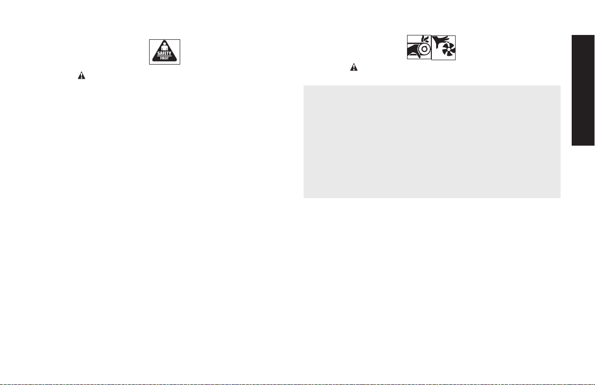
WARNING: RISK FROM MOVING PARTS
WHAT CAN HAPPEN HOW TO PREVENT IT
• Moving parts such as the
pulley, flywheel, and belt can
cause serious injury if they
come into contact with you or
your clothing.
• Never operate the compressor
with guards or covers which are
damaged or removed.
• Keep your hair, clothing and
gloves away from moving parts.
Loose clothes, jewelry or long
hair can be caught in moving
parts.
• Air vents may cover moving
parts and should be avoided as
well.
• Attempting to operate
compressor with damaged or
missing parts or attempting
to repair compressor with
protective shrouds removed
can expose you to moving
parts and can result in serious
injury.
• Any repairs required on this
product should be performed
by a D
EWALT factory service
center or a D
EWALT authorized
service center.
WARNING: RISK OF UNSAFE OPERATION
WHAT CAN HAPPEN HOW TO PREVENT IT
• Unsafe op er a tion of your air
compressor could lead to se ri-
ous in ju ry or death to you or
others.
• Review and understand all
instructions and warnings in
this manual.
• Be come fa mil iar with the op er-
a tion and con trols of the air
compressor.
• Keep operating area clear of all
persons, pets, and obstacles.
• Keep chil dren away from the air
compressor at all times.
• Do not operate the product
when fatigued or under the
influence of alcohol or drugs.
Stay alert at all times.
• Never defeat the safety fea tures
of this prod uct.
• Equip area of operation with a
fire extinguisher.
• Do not op er ate machine with
missing, broken, or un au tho-
rized parts.
• Never stand on the
compressor.
10
English
WARNING: RISK OF
INJURY FROM LIFTING
WHAT CAN HAPPEN HOW TO PREVENT IT
• Serious injury can result from
attempting to lift too heavy an
object.
• The compressor is too heavy
to be lifted by one person.
Obtain assistance from others
before lifting.
CAUTION: RISK FROM NOISE
WHAT CAN HAPPEN HOW TO PREVENT IT
• Under some conditions and
duration of use, noise from
this product may contribute to
hearing loss.
• Always wear certified safety
equipment: ANSI S12.6
(S3.19) hearing protection.
SAVE THESE INSTRUCTIONS FOR FUTURE
USE
Know Your Air Compressor
READ THIS OWNER’S MANUAL AND SAFETY RULES BEFORE
OPERATING YOUR UNIT. Compare the illustrations with your unit
to familiarize yourself with the location of various controls and
adjustments. Save this manual for future reference.
FEATURES
AUTO (-) / OFF (O) SWITCH
Place this switch (B) in the AUTO (-) position to
B
provide automatic power to the pressure switch
and OFF (O) to remove power at the end of each
use. NOTE: ALWAYS ensure the switch (B) is in
the OFF (O) position and unit is unplugged before
removing or replacing pressure switch cover.
PRESSURE SWITCH
The pressure switch (not shown) automatically starts the motor when
the air tank pressure drops below the factory set cut-in pressure. It
stops the motor when the air tank pressure reaches the factory set
cut-out pressure.
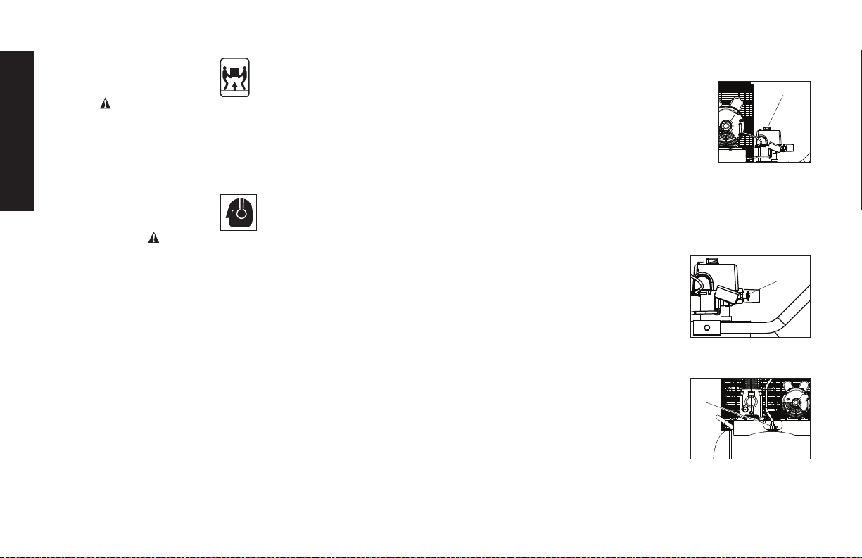
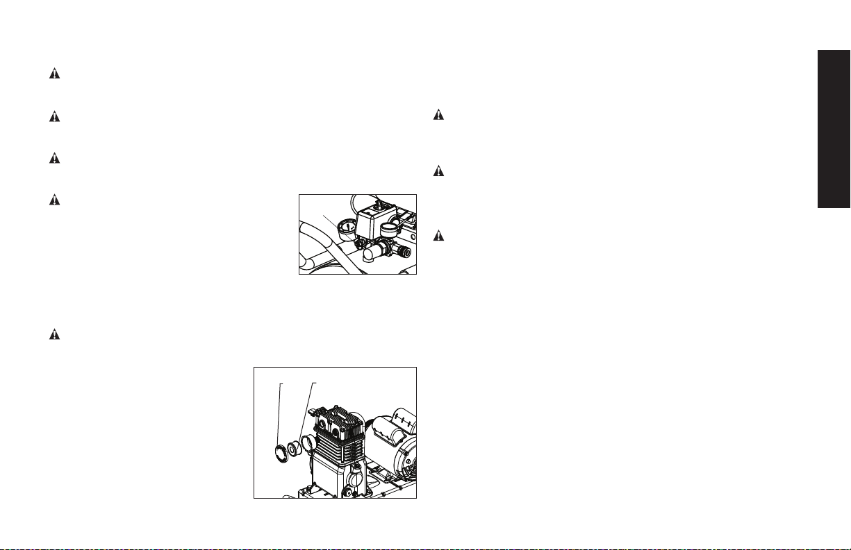
SAFETY VALVE
This valve (G) is designed to prevent system
G
failures by relieving pressure from the system
when the compressed air reaches a predeter-
mined level. The valve is preset by the manu-
facturer and must not be removed or modified
in any way.
CHECK VALVE
When the air compressor is operating, the
check valve (K) is open, allowing compressed
air to enter the air tank. When the air
compressor reaches cut-out pressure, the
check valve closes, allowing air pressure to
remain inside the air tank.
K
11
English
AIR INTAKE FILTER
The filter (A) is designed to clean air entering the
pump. To ensure the pump continually receives a
clean, cool, and dry air supply the filter must always
be clean and the filter intake must be free from
obstructions.
AIR TANK DRAIN VALVE
The drain valve (H) is located at the base of the air
tank and is used to drain condensation at the end
of each use. See Draining Air Tank under Maintenance.
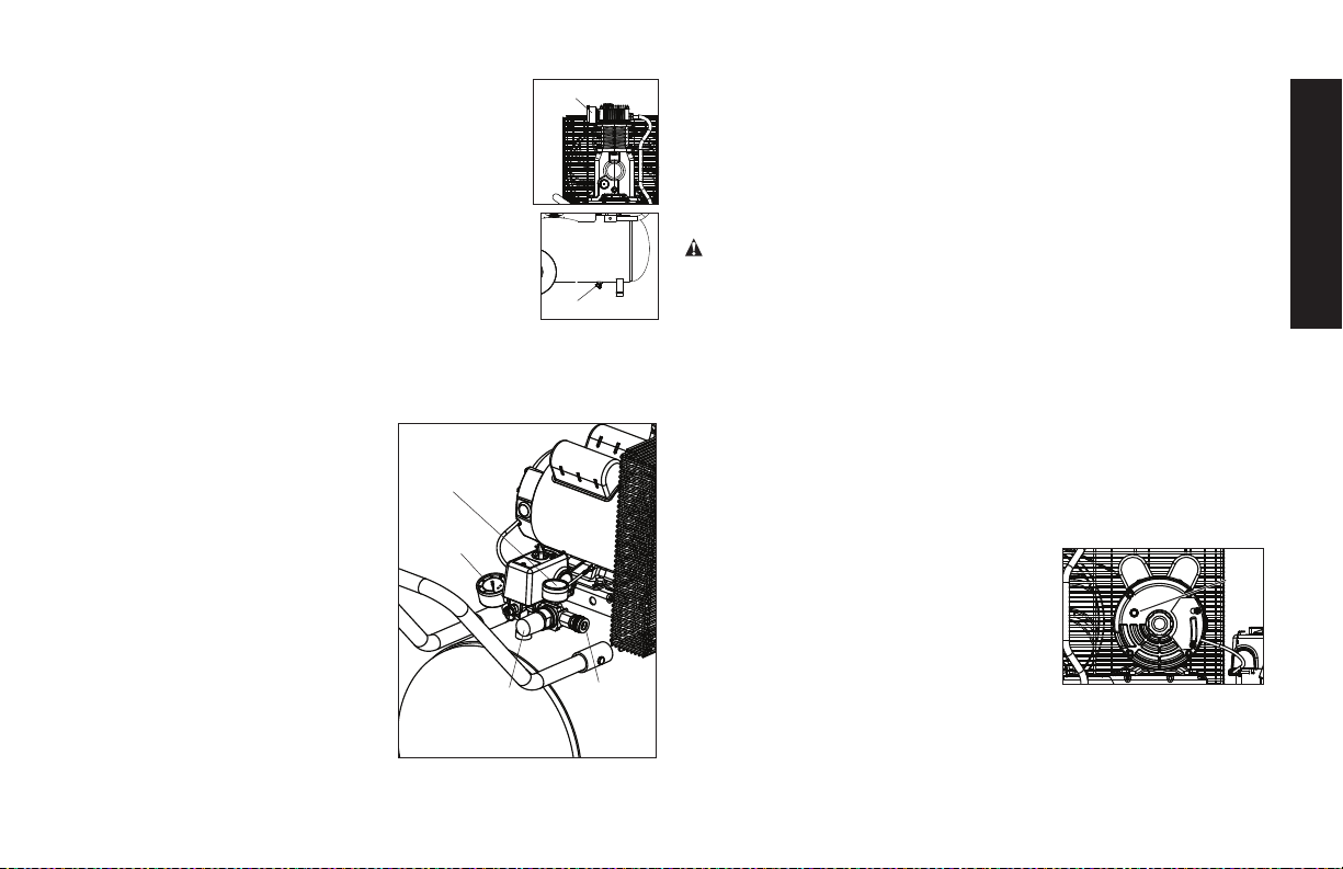
REGULATED PRESSURE GAUGE
The regulated pressure gauge (D) indicates the air pressure available
at the outlet side of the regulator. This pressure is controlled by the
regulator. The regulator is designed to allow pressures up to 150 PSI.
TANK PRESSURE GAUGE
The tank pressure gauge (C) indicates
D
C
L
E
the reserve air pressure in the tank.
UNIVERSAL QUICK CONNECT
BODY
The universal quick connect body (L)
accepts the three most popular
styles of quick connect plugs:
Industrial, automotive, and ARO.
One hand push-to-connect
operation makes connections
simple and easy.
REGULATOR
The regulator knob (E) controls the
air pressure coming from the air tank.
To Adjust Regulator:
Turn knob clockwise to increase regulated pressure and
counterclockwise to decrease regulated pressure.
WARNING: Risk of Bursting. Too much air pressure causes a
hazardous risk of bursting. Check the manufacturer’s maximum
pressure rating for air tools and accessories. The regulator outlet
pressure must never exceed the maximum pressure rating.
AIR COMPRESSOR PUMP
The pump compresses air into the air tank. Working air is not available
until the compressor has raised the air tank pressure above that
required at the air outlet.
MOTOR OVERLOAD PROTECTOR
The motor has a thermal overload protector. If the motor overheats for
any reason, the overload protector will shut off the motor. The motor
must be allowed to cool down before restarting. To restart:
1. Set the Auto/Off switch to OFF (O) and unplug unit.
2. Allow the motor to cool.
N
3. Depress the red reset button (N) on
the motor.
4. Plug the power cord into the correct
branch circuit receptacle.
5. Set the Auto/Off switch to AUTO (-).
H
A

12
English
INSTALLATION
Assembly
Unpack the air compressor. Inspect the unit for damage. If the
unit has been damaged in transit, contact the carrier and
complete a damage claim. Do this immediately because there
are time limitations to damage claims.
The carton should contain:
• air compressor
• handle
• operator's manual
• instruction sheet
Check the compressor’s specification label to ensure that you
have received the model ordered, and that it has the required
pressure rating for its intended use.
INSTALLING HOSES
WARNING: Risk of unsafe operation. Firmly grasp hose in hand
when installing or disconnecting to prevent hose whip.
1. Ensure regulated pressure gauge reads 0 PSI (0 kPa).
2. Grasp the hose at the quick connect plug and push the plug
into the quick connect body (L). Coupler will snap into place.
3. Grasp the hose and pull to ensure coupler is seated.
DISCONNECTING HOSES
WARNING: Risk of unsafe operation. Firmly grasp hose in hand
when installing or disconnecting to prevent hose whip.
1. Ensure regulated pressure gauge reads 0 PSI (0kPa).
2. Pull coupler on quick connect body back to release quick
connect plug on hose.
Lubrication and Oil
AIR COMPRESSOR
The air compressor pump was filled WITH oil at the manufacturer.
Check air compressor pump oil level before operating unit. See
Compressor Pump Oil under Maintenance.
Compatibility
Air tools and accessories that are run off the compressor must be
compatible with petroleum based products. If you suspect that a
material is not compatible with petroleum products, an air line filter
for removal of moisture and oil vapor in compressed air is required.
NOTE: Always use an air line filter to remove moisture and oil vapor
when spraying paint.
Location
• Locate the air compressor in a clean, dry, and well ventilated
area.
• Locate the air compressor at least 12” (30.5 cm) away from the
wall or other obstructions that will interfere with the flow of air.
• Locate the air compressor as close to the main power supply
as possible to avoid using long lengths of electrical wiring.
NOTE: Long lengths of electrical wiring could cause power
loss to the motor.
• The air filter must be kept clear of obstructions which could
reduce air flow to the air compressor.
HUMID AREAS
In frequently humid areas, moisture may form in the pump and
produce sludge in the oil, causing running parts to wear out
prematurely. Excessive moisture is especially likely to occur if
the unit is located in an unheated area that is subject to large
13
English
temperature changes. Two signs of excessive humidity are external
condensation on the pump when it cools down and a “milky”
appearance in compressor oil. You may be able to prevent
moisture from forming in the pump by increasing ventilation or
operating for longer intervals.
Electrical Wiring
WARNING: Improper electrical installation of this product may
void its warranty and your fire insurance. Have circuit wiring
performed by qualified personnel such as a licensed electrician who
is familiar with the current national electrical code and any prevailing
local electrical codes.
WARNING: Risk of electrical shock. Improper electrical grounding
can result in electrical shock. The wiring should be done by a
qualified electrician.
Refer to the air compressor’s specification label for the unit’s
voltage and amperage requirements.
For best performance and reliable starting, the air compressor
must be plugged into a dedicated circuit, as close as possible
to the fuse box or circuit breaker. The compressor will use the
full capacity of a typical 15 amp household circuit. If any other
electrical devices are drawing from the compressor’s circuit, the
compressor may fail to start. Low voltage or an overloaded circuit
can result in sluggish starting that causes the motor overload
protection system or circuit breaker to trip, especially in cold
conditions.
NOTE: A circuit breaker is recommended. If the air compressor is
connected to a circuit protected by a fuse, use only time
delay fuses.
WARNING: Risk of electrical shock. Electrical wiring must
be located away from hot surfaces such as manifold assembly,
compressor outlet tubes, heads, or cylinders.
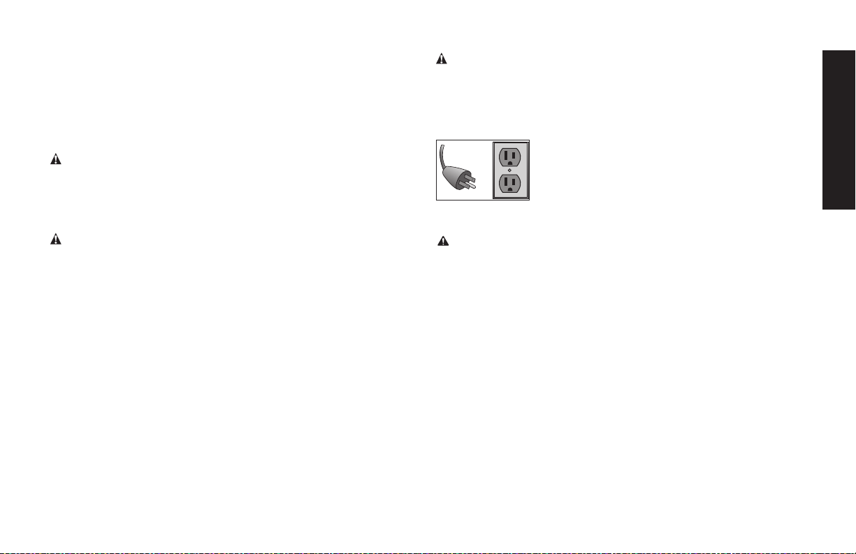
Grounding Instructions
1. This product must be grounded. In the event of an electrical
short circuit, grounding reduces the risk of
electrical shock by providing an escape wire for
the electric current. This product is equipped
with a cord having a grounding wire with an
appropriate grounding plug. The plug must be
plugged into an outlet that is properly installed and grounded in
accordance with all local codes and ordinances.
WARNING: Improper installation of the grounding plug is able to
result in a risk of electric shock. When repair or replacement of the
cord or plug is required, do not connect the grounding wire to either
flat blade terminal. The wire with insulation having an outer surface
that is green with or without yellow stripes is the grounding wire
2. Substitution of the signal word "DANGER" for "WARNING" is
not prohibited when the risk associated with the product is such
that a situation exists which if not avoided will result in death or
serious injury.
Check with a qualified electrician or serviceman when the
grounding instructions are not completely understood, or when
in doubt as to whether the product is properly grounded. Do not
modify the plug provided; if it does not fit the outlet, have the
proper outlet installed by a qualified electrician
3. This product is for use on a nominal 120-V circuit and has a
grounding plug similar to the plug illustrated in the figure. Only
connect the product to an outlet having the same configuration
as the plug. Do not use an adapter with this product.

14
English
DANGER: Risk of electrical shock. IMPROPER GROUNDING
CAN RESULT IN ELECTRICAL SHOCK.
• Do not modify the plug provided. If it does not fit the available
outlet, a correct outlet should be installed by a qualified
electrician.
• Repairs to the cord set or plug MUST be made by a qualified
electrician.
Extension Cords
If an extension cord must be used, be sure it is:
• a 3-wire extension cord that has a 3-blade grounding plug, and
a 3-slot receptacle that will accept the plug on the product
• in good condition
• plug is not worn
• no longer than 50 feet (15.2 m)
• 12 gauge (AWG) or larger. (Wire size increases as gauge number
decreases. 10 AWG and 8 AWG may also be used. DO NOT
USE 14 OR 16 AWG.)
NOTICE: The use of an undersized extension cord will cause
voltage to drop resulting in power loss to the motor and overheating.
Instead of using an extension cord, increase the working reach of
the air hose by attaching another length of hose to its end. Attach
additional lengths of hose as needed. Always use a minimum 3/8”
(9.5 mm) or greater air hose rated at 300 PSI.
Voltage and Circuit Protection
CAUTION: Certain air compressors can be operated on a
15 Amp circuit if the following conditions are met.
• Voltage supply to circuit must comply with the National
Electrical Code.
• Circuit is not used to supply any other electrical needs.
• Extension cords comply with specifications.
• Circuit is equipped with a 15 Amp circuit breaker or 15 Amp
time delay fuse.
NOTE: If compressor is connected to a circuit protected by fuses,
use only time delay fuses.
If any of the above conditions cannot be met, or if operation of the
compressor repeatedly causes interruption of the power, it may be
necessary to operate it from a 20 Amp circuit. It is not necessary to
change the cord set.
How to Use Your Unit (Fig 2)
How to Stop:
Set the Auto/Off switch to “OFF (O)”.
Before Starting
WARNING: Do not operate this unit until you read this instruction
manual for safety, operation and maintenance instructions.
Break-in Procedure
NOTICE: Risk of property damage. Serious damage may result if the
following break-in instructions are not closely followed.
This procedure is required before the air compressor is put into
service and when the check valve or a complete compressor pump
has been replaced.
1. Make sure the Auto/Off switch is in the “OFF (O)” position.
2. Check oil level in pump. See Oil paragraph in the Maintenance
section for instructions.
3. Plug the power cord into the correct branch circuit receptacle.
(Refer to Voltage and Circuit Protection paragraph in the
installation section of this manual.)
4. Open the drain valve fully to permit air to escape and prevent
air pressure build up in the air tank during the break-in period.

15
English
5. Move the Auto/Off switch to “AUTO (-)” position. The
compressor will start.
6. Run the compressor for 30 minutes. Make sure the drain valve
and all air lines are open so there is only a minimal air pressure
build-up in tank. NOTE: After about 30 minutes, If the unit does
not operate properly, SHUT DOWN IMMEDIATELY, and contact
Product Service.
7. Check all air line fittings and connections/piping for air leaks
by applying a soap solution. Correct if necessary. NOTE: Minor
leaks can cause the air compressor to overwork, resulting in
premature breakdown or inadequate performance.
8. Check for excessive vibration.
9. After 30 minutes, turn the Auto/Off switch to the “OFF (O)”
position.
10. Close the drain valve.
11. Turn the Auto/Off switch to the “AUTO (-)” position. The air
receiver will fill to “cut-out” pressure and the motor will stop.
The compressor is now ready for use.
Before Each Start-Up (Fig. 2)
1. Every day check the sight glass to ensure that the level of oil in
the pump is at the required level.
2. Place Auto/Off switch to “OFF (O)”.
3. Close the drain valve.
4. Visually inspect air lines and fittings for leaks.
5. Check safety valve. See To Check Safety Valve under
Maintenance.
6. Turn the regulator knob counterclockwise to set the outlet
pressure to zero.
7. Attach hose and accessories.
WARNING: Risk of unsafe operation. Firmly grasp air hose in
hand when installing or disconnecting to prevent hose whip.
WARNING: Risk of unsafe operation. Do not use damaged or
worn accessories.
NOTE: The hose or accessory will require a quick connect plug if
the air outlet is equipped with a quick connect socket.
WARNING: Risk of bursting. Too much air pressure causes a
hazardous risk of bursting. Check the manufacturer’s maximum
pressure rating for air tools and accessories. The regulator outlet
pressure must never exceed the maximum pressure rating.
CAUTION: Risk of unsafe operation. Compressed air from the
unit may contain wa ter condensation and oil mist. Do not spray un fil-
tered air at an item that could be damaged by moisture. Some air
tools and accessories may require filtered air. Read the in struc tions
for the air tools and accessories.
How to Start
1. Turn the Auto/Off switch to “AUTO (-)” and allow tank pressure
to build. Motor will stop when tank pressure reaches “cut-out”
pressure.
2. Turn the regulator knob clockwise to increase pressure.
IMPORTANT: When using regulator and other accessories refer to
the manufacturers instructions.
WARNING: Risk of bursting. If any unusual noise or vibration is
noticed, stop the compressor immediately and have it checked by a
trained service technician.
The compressor is ready for use.
16
English
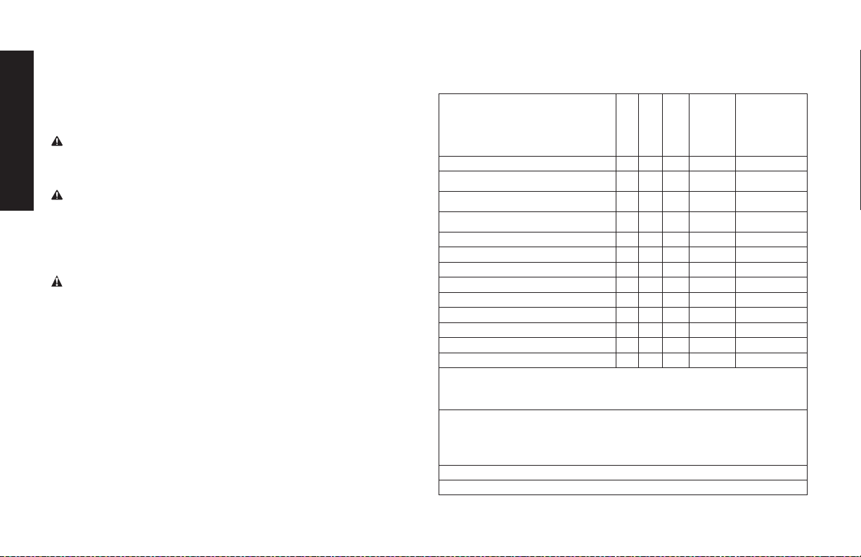
MAINTENANCE
Maintenance Chart
Procedure
Daily
Weekly
Monthly
1 year
or 100
Hours
See tank
warning
label
Check safety valve
X
Inspect air filter
X
+
Drain air tank
X
Check pump oil level
X
Change pump oil
X
**
+
Oil leak inspection
X
Inspect drive belt
X
Check drive belt tension
X
Check pulley/flywheel alignment
X
Check for unusual noise/vibration
X
Check for air leaks
X*
Clean compressor exterior
X
Remove tank from service
X
++
* To check for air leaks apply a solution of soapy water around joints.
While compressor is pumping to pressure and after pressure cuts out,
look for air bubbles to form.
** The pump oil must be changed after the first 20 hours of operation.
Thereafter, when using
full synthetic
non-detergent air compressor
oil, change oil every 100 hours of operation or once a year, whichever
comes first.
+ Perform more frequent in dusty or humid conditions.
++
For more information, call 1-888-895-4549 .
Shut-down (Fig. 2)
1. Move Auto/Off switch to the OFF (O) position.
NOTE: If finished using compressor, follow Steps 2 - 7.
2. Turn the regulator knob counterclockwise until fully closed. Ensure
regulated pressure gauge reads 0 PSI (0 kPa).
3. Remove hose and accessory.
WARNING: Risk of unsafe operation. Firmly grasp air hose in hand
when installing or disconnecting to prevent hose whip.
4. Drain the air tank,
see Draining Air Tank under Maintenance
.
Ensure air tank pressure gauge reads 0 PSI (0 kPa).
WARNING: Risk of bursting. Drain air tank daily. Water will
condense in air tank. If not drained, water will corrode and weaken
the air tank causing a risk of air tank rupture.
5. Allow the compressor to cool down.
6. Wipe air compressor clean and store in a safe, non-freezing area.
7. Unplug air compressor and wrap cord loosely around the handle.
WARNING: Risk of unsafe operation. Unit cycles automati-
cally when power is on. When performing maintenance, you may
be exposed to voltage sources, compressed air, or moving parts.
Personal injuries can occur. Before performing any maintenance or
repair, disconnect power source from the compressor and bleed off
all air pressure.
To ensure efficient operation and longer life of the air compressor
outfit, a routine maintenance schedule should be prepared and fol-
lowed. The following routine maintenance schedule is geared to an
outfit in a normal working environment operating on a daily basis.
If necessary, the schedule should be modified to suit the condi-
tions under which your compressor is used. The modifications will
depend upon the hours of operation and the working environment.
Compressor outfits in an extremely dirty and/or hostile environment
will require a greater frequency of all maintenance checks.
NOTE: See Operation section for the location of controls.
17
English
Checking Safety Valve
WARNING: Hot surfaces. Risk of burn. Tubes, pump head, and
surrounding parts are very hot, do not touch (see the Hot Surfaces
identified in Fig. 1). Allow compressor to cool prior to servicing.
WARNING: Risk of bursting. If the safety valve does not work
properly, over-pressurization may occur, causing air tank rupture
or an explosion.
WARNING: Risk from flying objects. Always wear certified safety
equipment: ANSI Z87.1 eye protection (CAN/CSA Z94.3) with side
shields.
WARNING: Risk from noise. Use ear
protection (ANSI S12.6 (S3.19) as air flow
noise is loud when draining.
Before starting compressor, pull the ring on
the safety valve (G) to make sure that the
safety valve operates freely. If the valve is
stuck or does not operate smoothly, it must
be replaced with the same type of valve.
Checking Air Filter
WARNING: Hot surfaces. Risk of burn. Tubes, pump head, and
surrounding parts are very hot, do not touch (see the Hot Surfaces
identified in Fig. 1). Allow compressor
to cool prior to servicing.
A dirty air filter will not allow the
compressor to operate at full
capacity. Keep the air filter clean at
all times.
1. Ensure Auto/Off switch (B) is
in the OFF (O) Position.
2. Allow unit to cool.
3. Unsnap the air filter cover
to remove (S).
4. Check the filter element (T). If it is dirty, blow compressed air
through the filter element for 10-15 seconds or replace
if needed. If the filter is filled with paint, replace it.
5. Place element into housing and reattach the air filter cover.
CAUTION: Risk of unsafe operation. Do not operate without air
filter.
Draining Air Tank (Fig. 2)
WARNING: Risk of unsafe operation. Air tanks contain high
pressure air. Keep face and other body parts away from outlet of
drain. Use eye protection [ANSI Z87.1 (CAN/CSA Z94.3)] when
draining as debris can be kicked up into face.
WARNING: Risk from noise. Use ear protection (ANSI S12.6
(S3.19) as air flow noise is loud when draining.
NOTE: All compressed air systems generate condensation that accu-
mulates in any drain point (e.g., tanks, filter, aftercoolers, dryers). This
condensate contains lubricating oil and/or substances which may be
regulated and must be disposed of in accordance with local, state,
and federal laws and regulations.
1. Set the Auto/Off switch to “OFF (O)”.
2. Turn the regulator knob counterclockwise to set the outlet
pressure to zero.
3. Remove the air tool or accessory.
4. Pull ring on safety valve allowing air to bleed from the tank until
tank pressure is approximately 20 PSI. Release safety valve
ring.
5. Drain water from air tank by opening drain valve on bottom of
tank.
G
S
T

18
English
WARNING: Risk of bursting. Water will condense in the air tank.
If not drained, water will corrode and weaken the air tank causing a
risk of air tank rupture.
NOTICE: Risk of property damage. Drain water from air tank may
contain oil and rust which can cause stains.
6. After the water has been drained, close the drain valve. The air
compressor can now be stored.
NOTE: If drain valve is plugged, release all air pressure. The valve
can then be removed, cleaned, then reinstalled.
Compressor Pump Oil (Fig. 3)
NOTICE: Risk of property damage. Use air compressor oil only.
Multi-weight automotive engine oils like 10W30 should not be used
in air compressors. They leave carbon deposits on critical compo-
nents, thus reducing performance and compressor life.
NOTE: Use full synthetic, non-detergent air compressor oil.
NOTE: Crankcase oil capacity is approximately 16.0 fluid ounces
(473ml).
WARNING: Drain tank to release air pressure before removing
the oil fill plug or oil drain plug.
Checking
WARNING: Drain tank to release air pressure before removing
the oil fill plug or oil drain plug.
1. The oil level should be to the middle of the sight glass (K).
2. If needed, remove oil fill plug (I) and slowly add oil until it
reaches the middle of the sight glass.
Changing
WARNING: Drain tank to release air pressure before removing the
oil fill plug or oil drain plug.
1. Remove the oil fill plug (I).
2. Remove the oil drain plug (J) and drain oil into a suitable con-
tainer.
3. Replace the oil drain plug (J) and tighten securely
4. Slowly add compressor oil until it reaches the middle of the
sight glass (K). NOTE: When filling the crankcase, the oil flows
very slowly into the pump. If the oil is added too quickly, it will
overflow and appear to be full.
CAUTION: Overfilling with oil will cause premature compressor
failure. Do not overfill.
5. Replace oil fill plug (I) and tighten securely.
19
English
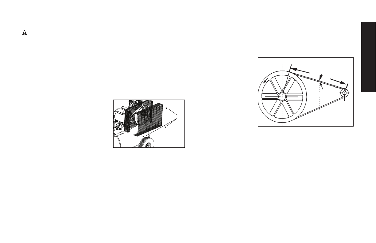
Belt Replacement
WARNING: This unit starts automatically. ALWAYS shut off
and unplug the compressor, and bleed all pressure from the
system before servicing the compressor, and when the
compressor is not in use. Do not use the unit with the shrouds
or belt guard removed. Serious injury could occur from contact
with moving parts. Hot surfaces. Risk of burn. Pump head, and
surrounding parts are very hot, do not touch (see the Hot
Surfaces identified in Fig. 1). Allow compressor to cool prior to
servicing.
1. Set the Auto/Off lever to “OFF (O)”, unplug the unit, and relieve
all air pressure from the air tank.
2. Remove the outer belt guard (Z).
3. Mark motor position on saddle.
4. Loosen the motor mounting
screws and slide the motor
toward the air compressor pump.
5. Remove the belt and replace
with a new one.
6. See the Adjusting BeltTension before
tightening motor mounting screws.
Z
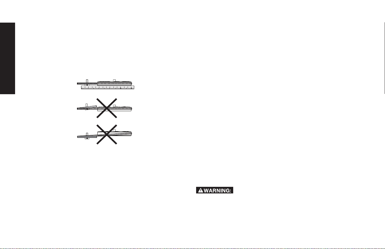
Adjusting Belt Tension
1. Slide motor into original position, line the motor up with the
mark made earlier on saddle.
2. Tighten two outside motor mounting screws enough to hold
the motor in place for checking pulley and flywheel alignment.
3. The belt should
deflect 1/4" (6.5mm)
at midway between
the pulley and the
flywheel when a 10
pound (4.5kg.) weight
is applied at the mid-
way point.
4. When proper belt ten-
sion is achieved, tight-
en motor mounting
screws. Torque to
20-25 ft-lbs (27.1-33.9 Nm.)
NOTE: Once the motor pulley has been moved from its factory set
location, the grooves of the flywheel and pulley must be aligned to
within 1/16" (1.6 mm) to prevent excessive belt wear. Verify the
alignment by performing the following Motor Pulley/Flywheel -
Alignment.
Downward Force
Deflection
20
English
Motor Pulley/Flywheel Alignment
NOTE: Once the motor pulley has been moved from its factory set
location, the grooves of the flywheel and pulley must be aligned to
within 1/16" (1.6 mm) to prevent excessive belt wear.
The air compressor flywheel and motor pulley hub must be in-line
(in the same plane) within 1/16" (1.6 mm) to assure belt retention
within flywheel belt grooves. To correct misalignment, perform the
following steps:
1. Set the Auto/Off lever to “OFF (O)”, unplug the unit, and
relieve all air pressure from the air tank.
2. Remove the outer belt guard.
3. Loosen the motor mounting bolts.
4. Loosen the set screws on the motor pulley.
5. Align the motor pulley with the pump flywheel.
6. Retighten the motor pulley set screws. Torque 145-180 in.-lbs
(16.4-20.3 Nm.).
7. Adjust the proper belt tension.
8. Retighten the motor mounting bolts. Torque to 20-25 ft.-lbs
(27.1–33.9 Nm)
9. Reinstall the outer belt guard.
All moving parts must be guarded.
Air Compressor Pump Intake and Exhaust
Valves
Once a year have a Trained Service Technician check the air com-
pressor pump intake and exhaust valves.
Inspect Air Lines and Fittings for Leaks
1. Set the Auto/Off lever to “OFF (O)”, unplug the unit, and relieve
all air pressure from the air tank.
2. Apply a soap solution to all air line fittings and connections/
piping.
3. Correct any leaks found.
IMPORTANT: Even minor leaks can cause the air compressor
to overwork, resulting in premature breakdown or inadequate
performance.
Air compressor Head Bolts - Torquing
The air compressor pump head bolts should be kept properly
torqued. Check the torques of the head bolts after the first five
hours of operation. Torque to 15-20 ft.-lbs (20.3-27.1 Nm).
Service and Adjustments
ALL MAINTENANCE AND REPAIR OPERATIONS NOT LISTED
MUST BE PERFORMED BY TRAINED SERVICE TECHNICIAN.
Risk of unsafe operation. Unit cycles automati-
cally when power is on. When servicing, you may be exposed
to voltage sources, compressed air, or moving parts. Before
servicing unit unplug or disconnect electrical supply to the air
compressor, bleed tank of pressure, and allow the air compres-
sor to cool.
21
English
To Replace or Clean Check Valve
1. Release all air pressure from air tank. See Draining Air Tank in
the Maintenance section.
2. Set the Auto/Off lever to “Off”, unplug the unit, and relieve all
air pressure from the air tank.
3. Using an adjustable wrench loosen outlet tube nut at air tank
and pump. Carefully move outlet tube away from check valve.
4. Using an adjustable wrench loosen pressure relief tube nut at
air tank. Carefully move pressure relief tube away from check
valve.
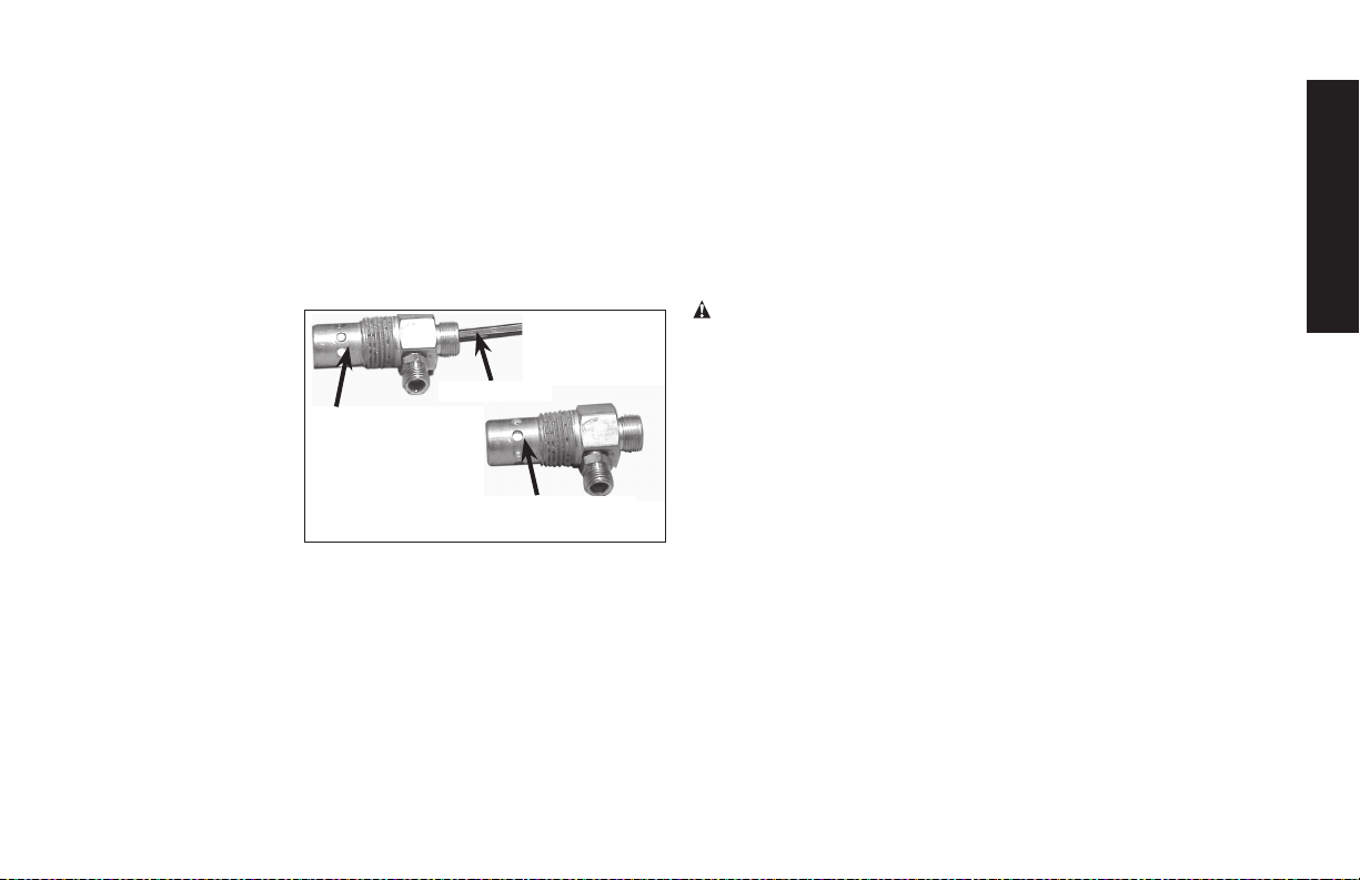
5. Unscrew the check
In closed position
disc is visible.
In open
position
nothing is
visible.
Screwdriver
valve (turn counter-
clockwise) using a
13/16" open end
wrench. NOTE: the
orientation for
reassembly.
6. Using a screw-
driver, carefully
push the valve disc
up and down.
NOTE: The valve disc should move freely up and down on
a spring which holds the valve disc in the closed position,
if not, the check valve needs to be cleaned or replaced.
7. Clean or replace the check valve. A solvent, such as paint or
varnish remover can be used to clean the check valve.
8. Apply sealant to the check valve threads. Reinstall the check
valve (turn clockwise) to proper orientation.
9. Replace the pressure release tube. Tighten nuts.
10. Replace the outlet tube and tighten nuts.
11. Perform the Break-in Procedure. See Break-in Procedure in
the Operation section.
Additional Service
Disassembly or service of the air compressor beyond what is cov-
ered in this manual is not recommended. If additional service is
required, contact your nearest Authorized Warranty Service Center.
Accessories
Recommended accessories for use with your tool are available for
purchase from your local dealer or authorized service center. If you
need assistance in locating any accessory for your tool, please call
1-888-895-4549 or visit our website www.dewalt.com.
WARNING: The use of any other accessory not recommended
for use with this tool could be hazardous. Use only accessories
rated equal to or higher than the rating of the air compressor.
Service Information
Please have the following information available for all service calls:
Model Number ____________ Serial Number ___________
Date and Place of Purchase ____________________________
Repairs
To assure product SAFETY and RELIABILITY, repairs, maintenance
and adjustment should be performed by a D
E
WALT factory service
center, a D
E
WALT authorized service center or other qualified
service personnel. Always use identical replacement parts.

22
English
Limited Warranty
DEWALT Industrial Tools are warranted from date of purchase.
2 Year – Limited warranty on oil-lubricated air
compressor pumps.
1 Year – Limited warranty on all other air compressor
components. This warranty is not transferable to
subsequent owners.
D
E
WALT will repair or replace, without charge, at D
E
WALT’s option,
any defects due to faulty materials or workmanship. For further
detail of warranty coverage and warranty repair information, call
1-(888)-895-4549 or visit dewalt.com. This warranty does not
apply to accessories or damage caused where repairs have been
made or attempted by others. This warranty also does not apply
to merchandise sold by D
E
WALT which has been manufactured
by and identied as the product of another company, such as
gasoline engines. Such manufacturer’s warranty, if any, will apply.
ANY INCIDENTAL, INDIRECT OR CONSEQUENTIAL LOSS,
DAMAGE OR EXPENSE THAT MAY RESULT FROM ANY
DEFECT, FAILURE OR MALFUNCTION OF THE PRODUCT
IS NOT COVERED BY THIS WARRANTY. Some states do not
allow the exclusion of limitation of incidental or consequential
damages, so the above limitation or exclusion may not apply
to you. IMPLIED WARRANTIES, INCLUDING THOSE OF
MERCHANTABILITY OR FITNESS FOR A PARTICULAR
PURPOSE, ARE LIMITED TO ONE YEAR FROM THE DATE OF
ORIGINAL PURCHASE. Some states do not allow limitations on
how long an implied warranty lasts, so the above limitations may
not apply to you.
What the Company Will Do: (the company) will cover parts
and labor to remedy substantial defects due to materials
and workmanship during the rst year of ownership, with the
exceptions noted below. Parts used in repair of whole goods or
accessories are warranted for the balance of the original warranty
period.
What is not covered Under This Warranty? Failures by the
original retail purchaser to install, maintain, and operate said
equipment in accordance with standard industry practices.
Modications to the product, or tampering with components,
or failure to comply with the specic recommendations of the
Company set forth in the owner’s manual, will render this warranty
null and void. The Company shall not be liable for any repairs,
replacements, or adjustments to the equipment, or any costs for
labor performed by the purchaser without the Company’s prior
written approval. The effects of corrosion, erosion, surrounding
environmental conditions, cosmetic defects, and routine
maintenance items, are specically excluded from this warranty.
Routine maintenance items such as: oil, lubricants, and air lters,
as well as changing oil, air lters, belt tensioning, etc… fall under
the owner’s responsibility. Additional exclusions include: freight
damage, failures resulting from neglect, accident, or abuse,
induction motors when operated from a generator, oil leaks, air
leaks, oil consumption, leaky ttings, hoses, drain valve, bleeder
tubes, and transfer tubes.
• The following components are considered normal wear
items and are not covered after the rst year of
ownership: Belts, pulleys, ywheels, check valves,
pressure switches, air unloaders, throttle controls,
electric motors, brushes, regulators, o-rings, pressure
gauges, tubing, piping, ttings, fasteners, wheels, quick
couplers, gaskets, seals, air lter housings, piston rings,
connecting rods, and piston seals.

23
English
• Labor, service calls, and travel charges, are not covered
after the rst year of ownership on stationary
compressors (compressors without handles, or wheels).
Repairs requiring overtime, weekend rates, or any other
charges beyond the standard shop labor rate are not
covered.
• Time required for orientation training for the service
center to gain access to the product, or additional time
due to inadequate egress.
• Damage caused by incorrect voltage, improperly wired,
or failure to have a certied licensed electrician install
the compressor, will render this warranty null and void.
• Damage caused from inadequate lter maintenance.
• Pump wear or valve damage caused by using oil not
specied.
• Pump wear or damage caused by any oil contamination.
• Pump wear or valve damage caused by failure to follow
proper maintenance guidelines.
• Operation below proper oil level or operation without oil.
• Gas Engines, if product is equipped with a gas engine,
see engine manual for specic engine manufacturer’s
warranty coverage.
Parts purchased separately: The warranty for parts purchased
separately such as: pumps, motors, etc., are as follows:
From Date of Purchase
• All single & two stage pumps 1 year
• Electric motors 90 days
• Universal motor/pump 30 days
• All other parts 30 days
• No return authorization will be issued for electrical
components once items are installed.
How do You Get Service? In order to be eligible for service
under this warranty you must be the original retail purchaser,
and provide proof of purchase from one of the Company’s
dealers, distributors, or retail outlet stores. Portable compressors
or components must be delivered, or shipped, to the nearest
Authorized Service Center. All associated freight costs and travel
charges must be borne by the consumer. Please call our toll free
number 1-888-895-4549 for assistance.
THIS WARRANTY GIVES YOU SPECIFIC LEGAL RIGHTS, AND
YOU MAY ALSO HAVE OTHER RIGHTS WHICH VARY FROM
STATE TO STATE.
THE COMPANY MAKES NO OTHER WARRANTY OR
REPRESENTATION OF ANY KIND WHATSOEVER,
EXPRESSED OR IMPLIED, EXCEPT THAT OF TITLE. ALL
IMPLIED WARRANTIES, INCLUDING ANY WARRANTY
OF MERCHANTABILITY AND FITNESS FOR PARTICULAR
PURPOSE ARE HEREBY DISCLAIMED. LIABILITY FOR
CONSEQUENTIAL AND INCIDENTAL DAMAGES UNDER ANY
AND ALL WARRANTIES, OTHER CONTRACTS, NEGLEGENCE,
OR OTHER TORTS IS EXCLUDED TO THE EXTENT EXCLUSION
IS PERMITTED BY LAW.
24
English
FREE WARNING LABEL REPLACEMENT: If your warning labels
become illegible or are missing, call 1-888-895
-
4549 for a free
replacement.
HOT SURFACE. RISK OF
BURNS. DO NOT TOUCH.
SUPERFICIE CALIENTE.
RIESGO DE QUEMADURAS.
NO TOCAR.
RISQUES DE BRÛLURES.
NE PAS TOUCHER.
N008 806
SUURFACE TR
È
S CHAUDE.
GLOSSARY
CFM: Cubic feet per minute.
SCFM: Standard cubic feet per minute; a unit of measure of air
delivery.
PSI: Pounds per square inch; a unit of measure of pressure.
Cut-in pressure: Factory set low pressure point that starts the
compressor to repressurize the tank to a higher pressure.
Cut-out pressure: Factory set high pressure point that stops
the compressor from increasing the pressure in the tank above a
certain level.
Well-ventilated: A means of providing fresh air in exchange for
dangerous exhaust or vapors.
Dedicated circuit: An electrical circuit reserved for the exclusive
use of the air compressor.
ASME: American Society of Mechanical Engineers. Indicates that
the components are manufactured, tested and inspected to the
specifications set by ASME.
CSA: Canadian Standards Association
Indicates that the products that have this marking have
been manufactured, tested and inspected to standards
that are set by CSA.
Canadian Standards Association (USA): Indicates that the
products that have this marking have been
manufactured, tested and inspected to standards that
are set by CSA. These products also conform to U.L.
standard 1450.
California Code: Unit may comply with California Code 462 (l) (2)/
(M) (2). Specification/model label is on the side of the air tank on
units that comply with California Code.

25
English
Troubleshooting Guide
This section provides a list of the more frequently encountered malfunctions, their causes and corrective actions. The operator or
maintenance personnel can perform some corrective actions, and others may require the assistance of a qualified D
EWALT technician or
your dealer.
Problem Code
Air leaks .................................................................................................................................... 1
Air leaks in air tank or at air tank welds ....................................................................................2
Air leaks between head and valve plate ....................................................................................3
Air leaks from safety valve .........................................................................................................4
Compressor is not supplying enough air to operate accessories ............................................1, 5, 6, 7, 9, 10
Restricted air intake. ..................................................................................................................9
Oil in discharge air .....................................................................................................................9, 19, 31
Knocking Noise .........................................................................................................................4, 10, 11, 12, 13, 14
Excessive belt wear ...................................................................................................................10, 11, 14, 15
Squealing sound ........................................................................................................................10
Moisture in pump crankcase ..................................................................................................... 1, 3, 8, 17, 18, 19, 20, 21, 22
Excessive current draw .............................................................................................................14, 26, 27
Compressor won’t start in cold temperatures ..........................................................................17, 34, 35
Pressure reading on the regulated pressure gauge drops when an accessory is used ........... 23
Regulator knob has continuous air leak ....................................................................................24
Regulator will not shut off air outlet ..........................................................................................24
Air tank pressure will not build ..................................................................................................25
Compressor stalls ......................................................................................................................28, 29, 30
Overheating ...............................................................................................................................27, 32, 33

26
English
Troubleshooting Codes
CODE POSSIBLE CAUSE POSSIBLE SOLUTION
1 Fittings are not tight. Tighten fittings where air can be heard escaping. Check fittings
with soapy water solution. DO NOT OVERTIGHTEN.
2 Defective air tank. Air tank must be replaced. Do not repair the leak.
WARNING: Risk of bursting. Do not drill into, weld or otherwise
modify air tank or it will weaken. The air tank can rupture or
explode.
3 Leaking seals. Contact a D
EWALT factory service center or a D
E
WALT authorized
service center.
4 Defective safety valve. Operate safety valve manually by pulling on ring. If valve still
leaks, it must be replaced.
5 Prolonged excessive use of air. Decrease amount of air usage.
6 Compressor is not large enough for accessory. Check the accessory air requirement. If it is higher than the SCFM
or pressure supplied by your air compressor, a larger compressor
is needed to operate accessory.
7 Hole in air hose. Check and replace air hose, if required.
8 Unit operating in damp or humid conditions. Move unit to a dry, well ventilated area.
9 Restricted air intake filter. Clean or replace air intake filter.
10 Loose belt. Check belt tension, see Adjusting Belt Tension under
Maintenance.
11
Loose pulley. Tighten pulley set screw, torque to 145-180 in.-lbs. (16.4–20.3Nm).
12
Loose flywheel. Tighten flywheel screw, torque to 13–16 ft.-lbs. (17.6–21.7 Nm).
13
Carbon build-up in pump. Contact a D
E
WALT factory service center or a D
E
WALT authorized
service center.

27
English
CODE POSSIBLE CAUSE POSSIBLE SOLUTION
14
Belt too tight. Check belt tension, see Adjusting Belt Tension under
Maintenance.
15
Pulley misalignment. See Motor Pulley/Flywheel Alignment under Maintenance.
16
Pump oil is low. Add full synthetic, non-detergent air compressor oil to pump. See
Compressor Pump Oil under Maintenance.
17
Detergent type oil being used in pump. Drain oil and refill pump with full synthetic non-detergent air com-
pressor oil.
18
Extremely light duty cycles. Run unit for longer duty cycles.
19
Piston rings damaged or worn. Contact a D
E
WALT factory service center or a D
E
WALT authorized
service center.
20
Cylinder or piston damaged or worn. Contact a D
E
WALT factory service center or a D
E
WALT authorized
service center.
21
Compressor cylinder finish worn. Contact a DEWALT factory service center or a D
E
WALT authorized
service center.
22
Water in pump oil. Drain oil and refill pump with full synthetic non-detergent air
compressor oil.
23
Regulator is not adjusted correctly for accessory
being used.
It is normal for some pressure drop to occur when and acces-
sory is used, adjust the regulator as instructed in Regulator under
Features if pressure drop is excessive.
NOTE: Adjust the regulated pressure under flow conditions while
the accessory is being used.
24
Damaged regulator. Replace
25
Regulator open. Rotate the regulator knob counter-clockwise to its built-in stop.

28
English
CODE POSSIBLE CAUSE POSSIBLE SOLUTION
26
Low voltage/motor overload. Check that power supply is adequate and that compressor is
on a dedicated circuit. If using extension cord, try using without.
If compressor is connected to a circut protected by a fuse, use
time delay fuses.
27
Restricted air passages. Inspect and replace transfer tubes or check valve, as
required.
28
Low voltage motor. Furnish adequate power.
29
Bad check valve. Replace check valve.
30
Seized pump. Contact a D
E
WALT factory service center or a D
E
WALT authorized
service center.
31
Oil level too high. Reduce to proper level. See Compressor Pump Oil under
Maintenance.
32
Poor ventilation. Relocate compressor to an area with cool, dry, well circulated
air, at least 12 in. from nearest wall.
33
Dirty cooling surfaces. Clean all cooling surfaces thoroughly.
34
Too much back pressure in tank. Open drain valve when starting motor.
35
Compressor too cold. Move compressor to a warmer location.
