English
Français
Español
OPERATING MANUAL
MODE D’EMPLOI
MANUAL DE FUNCIONAMIENTO
AIR CONDITIONER
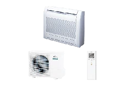
Floor Type
KEEP THIS OPERATING MANUAL FOR FUTURE REFERENCE
CONSERVER CE MANUEL D’UTILISATION POUR POUVOIR LE CONSULTER ULTÉRIEUREMENT
CONSERVE ESTE MANUAL DE FUNCIONAMIENTO PARA FUTURA REFERENCIA
PART NO. 9378532076
9378532076_OM.indb cover19378532076_OM.indb cover1 9/24/2013 4:35:25 PM9/24/2013 4:35:25 PM
En-2
SAFETY PRECAUTIONS
To prevent personal injury, injury to others, or property damage, read this section carefully before you use this product, and be sure to comply to the
following safety precautions.
Incorrect operation due to failure to follow the instructions may cause harm or damage, the seriousness of which is classifi ed as follows:
WARNING CAUTION
This mark warns of death or serious injury. This mark warns of injury or damage to property.
• Explanation of symbols displayed on the indoor unit or outdoor unit.
WARNING
This symbol shows that this appliance uses a fl ammable refrigerant. If the refrigerant is leaked and exposure to an external
ignition source, there is a risk of fi re.
CAUTION
This symbol shows that the Operation Manual should be read carefully.
CAUTION
This symbol shows that a service personnel should be handling this equipment with reference to the Installation Manual.
CAUTION
This symbol shows that information is available such as the Operating Manual or Installation Manual.
WARNING
●
Do not attempt to install this air conditioner by yourself.
●
This unit contains no user-serviceable parts. Always consult authorized service personnel for repairs.
●
When moving, consult authorized service personnel for disconnection and installation of the unit.
●
Do not become excessively chilled by staying for lengthy periods in the direct cooling airfl ow.
●
Do not insert anything into the Airfl ow direction.
●
Do not start and stop air conditioner operation by disconnecting the power supply cord.
●
Take care not to damage the power supply cord.
●
If the power supply cord of this appliance is damaged, it should only be replaced by the authorized service personal, since special
purpose tools and specifi ed cord are required.
●
In the event of a malfunction (burning smell, etc.), immediately stop operation, turn off the breaker, and consult authorized service
personnel.
●
In the event of refrigerant leakage, be sure to keep away from fi re or any fl ammables. (consult an authorized service personnel)
CAUTION
●
Provide occasional ventilation during use.
●
Do not direct airfl ow at fi replaces or heating apparatus.
●
Do not climb on, or place objects on, the air conditioner.
●
Do not hang objects from the indoor unit.
●
Do not set fl ower vases or water containers on top of air conditioners.
●
Do not place any other electrical products or household belongings under indoor unit or outdoor unit. Dripping condensation from the
unit might get them wet, and may cause damage or malfunction of your property.
●
Do not expose the air conditioner directly to water.
●
Do not operate the air conditioner with wet hands.
●
Do not pull power supply cord.
●
Turn off power source when not using the unit for extended periods.
●
Check the condition of the installation stand for damage.
●
Do not place animals or plants in the direct path of the airfl ow.
●
Do not drink the water drained from the air conditioner.
●
Do not use in applications involving the storage of foods, plants or animals, precision equipment, or art works.
●
Do not touch the aluminum fi ns of heat exchanger built-in the indoor or outdoor unit to avoid personal injury when you install or
maintain the unit.
●
Connection valves become hot during Heating; handle with care.
●
Do not apply any heavy pressure to radiator fi ns.
●
Operate only with air fi lters installed.
●
Do not block or cover the intake grille and outlet port.
●
Ensure that any electronic equipment is at least 40 in. (1 m) away from either the indoor or outdoor units.
●
Avoid installing the air conditioner near a fi replace or other heating apparatus.
●
When installing the indoor and outdoor unit, take precautions to prevent access to infants.
●
Do not use infl ammable gases near the air conditioner.
●
Do not sit and place anything on the unit.
●
This appliance is not intended for use by persons (including children) with reduced physical, sensory or mental capabilities, or lack
of experience and knowledge, unless they have been given supervision or instruction concerning use of the appliance by a person
responsible for their safety. Children should be supervised to ensure that they do not play with the appliance.
SAFETY PRECAUTIONS ........................................En-2
FEATURES AND FUNCTIONS ...............................En-3
NAME OF PARTS ...................................................En-4
PREPARATION .......................................................En-6
OPERATION ............................................................En-7
TIMER OPERATION ...............................................En-8
ADJUSTING THE DIRECTION OF AIR
CIRCULATION ......................................................En-10
AIR OUTLET SELECTION .................................... En-11
MIN. (MINIMUM) HEAT OPERATION ...................En-12
ECONOMY OPERATION ......................................En-12
SWING OPERATION ............................................En-13
MANUAL AUTO OPERATION ...............................En-13
POWERFUL OPERATION ....................................En-13
CLEANING AND CARE .........................................En-14
TROUBLESHOOTING ..........................................En-16
OPERATING TIPS .................................................En-18
CONTENTS
PART NO. 9378532076
9378532076_OM.indb 29378532076_OM.indb 2 9/24/2013 4:35:26 PM9/24/2013 4:35:26 PM
En-3
FEATURES AND FUNCTIONS
INVERTER
At the start of operation, large amount of power is used to
bring the room quickly to the desired temperature. Afterwards,
the unit automatically switches to a low power setting for eco-
nomic and comfortable operation.
AUTO CHANGEOVER
The operation mode (cooling, dry, heating) is switched auto-
matically to maintain the set temperature, and the temperature
is kept constant at all times.
MIN. (MINIMUM) HEAT OPERATION
The room temperature can be maintained at 50°F (10°C) so as
to prevent the room temperature from falling too far.
ECONOMY OPERATION
When economy operation mode is operated, the room temper-
ature will be little higher than the set-temp under cooling mode
and lower than set-temp under heating mode. Therefore, the
economy mode is able to save more energy than other normal
mode.
PROGRAM TIMER
The program timer allows you to integrate OFF timer and ON
timer operations in a single sequence. The sequence can
involve 1 transition from OFF timer to ON timer, or from ON
timer to OFF timer, within a 24 hour period.
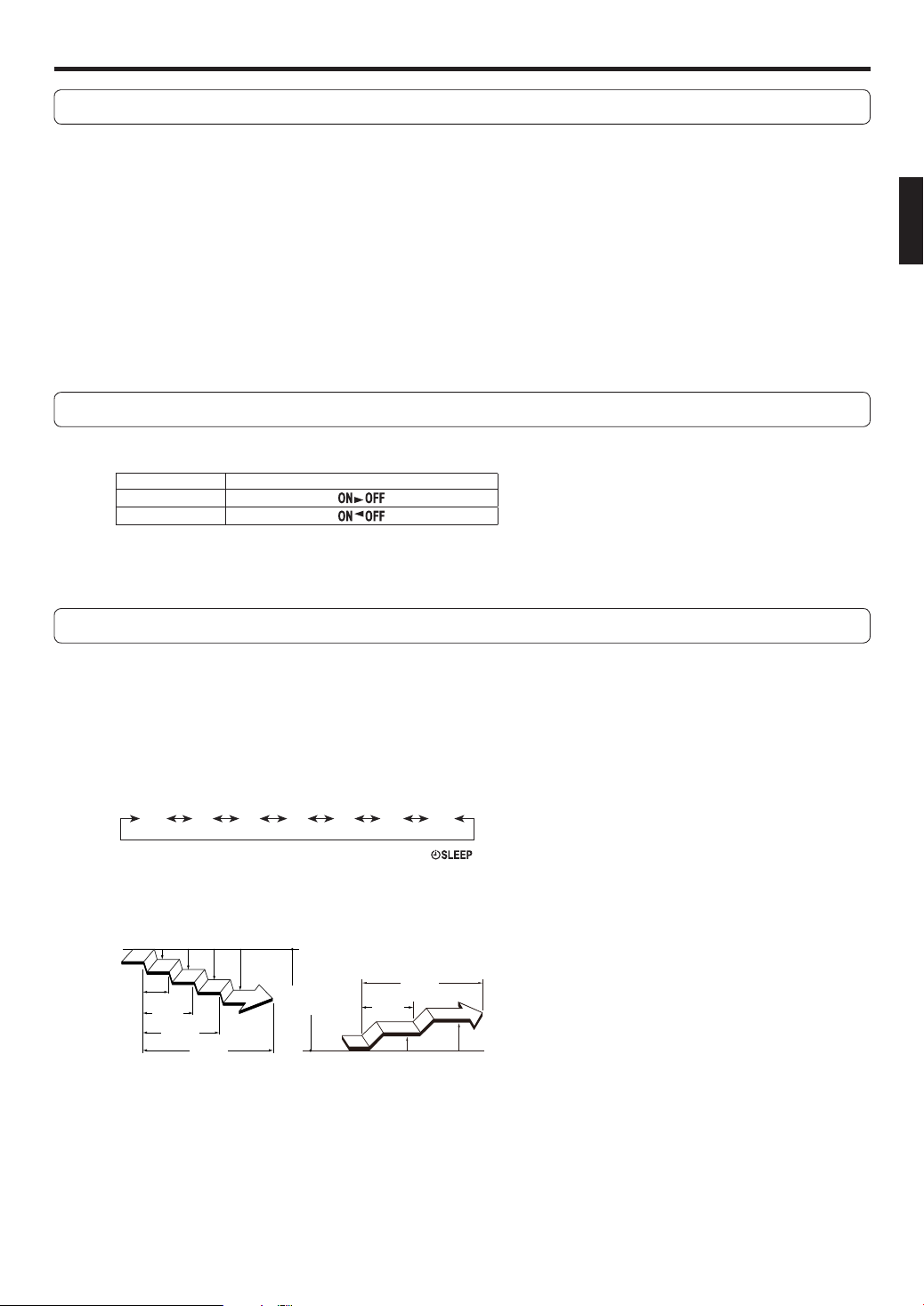
SLEEP TIMER
When the SLEEP button is pressed during Heating mode, the
air conditioner’s temperature setting is gradually lowered dur-
ing the period of operation; during cooling mode, the tempera-
ture setting is gradually raised during the period of operation.
When the set time is reached, the unit automatically turns off.
WIRELESS REMOTE CONTROLLER
The Wireless Remote Controller allows convenient control of
air conditioner operation.
SWING OPERATION
The Airflow Direction Louvers swings automatically up and
down so that the air speeds to every nook and corner of your
room.
REMOVABLE OPEN PANEL
The indoor unit’s Open Panel can be removed for easy clean-
ing and maintenance.
MILDEW-RESISTANT FILTER
The AIR FILTER has been treated to resist mildew growth,
thus allowing cleaner use and easier care.
SUPER QUIET OPERATION
When the FAN button is used to select QUIET, the unit begins
super-quiet operation; the indoor unit’s airfl ow is reduced to
produce quieter operation.
POLYPHENOL CATECHIN AIR CLEANING FILTER
The polyphenol catechin air cleaning fi lter uses static electric-
ity to clean the air of fi ne particles and dust such as tobacco
smoke and plant pollen that are too small to see.
The fi lter contains catechin, which is highly effective against
various bacteria by suppressing the growth of the bacteria ad-
sorbed by the fi lter.
Note that when the air cleaning fi lter is installed, the amount
of air produced decreases, causing a slight decrease in the air
conditioner's performance.
NEGATIVE AIR IONS DEODORIZING FILTER
It comprises pottery super micro particles, which can produce
negative air ions having the effect of deodorizing and can ab-
sorb and remit the peculiar smell at home.
WIRED REMOTE CONTROLLER (OPTION)
The optional wired
remote
controller can be used.
When you use remote controller, there are following different
points as compared with using wireless remote controller.
[The additional functions for wired ones]
• Weekly timer
• Temperature set back timer
And you can use both wired and wireless remote controller si-
multaneously.
(But function is limited)
When the restricted functions on the remote controller are
used, beeping sound will be heard, OPERATION, TIMER and
the 3rd lamp of the indoor unit will fl ash.
[The restricted functions for wireless ones]
• SLEEP TIMER
• TIMER
• MIN. HEAT
• POWERFUL OPERATION
POWERFUL OPERATION
The product will operate at maximum power, which is convenient
when you want to quickly cool down or warm up the room.
9378532076_OM.indb 39378532076_OM.indb 3 9/24/2013 4:35:26 PM9/24/2013 4:35:26 PM
En-4
E
F
9
9
4
1
A=
D
C
1
4
GB
7
TIMER
6
OPERATION
58
ECONOMY
2 3
Fig. 1
Fig. 5
Fig. 2
Fig. 3
Fig. 4
NAME OF PARTS
4')7
9378532076_OM.indb 49378532076_OM.indb 4 9/24/2013 4:35:26 PM9/24/2013 4:35:26 PM
En-5
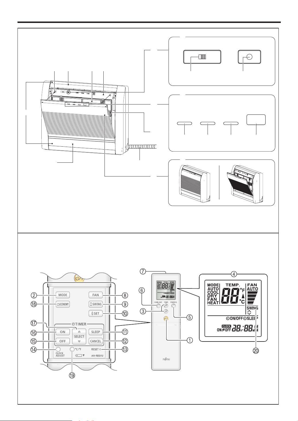
Fig. 1 Indoor Unit
1
Operating Control Panel (Fig. 2)
2
Air Outlet Selection switch
3
MANUAL AUTO button
●
When the MANUAL AUTO button is pressed
in for more than 10 seconds, the forced
cooling operation will start.
●
The forced cooling operation is used at the
time of installation.
Only for authorized service personnel's use.
●
When the forced cooling operation starts by
any chance, press the START/STOP button
to stop the operation.
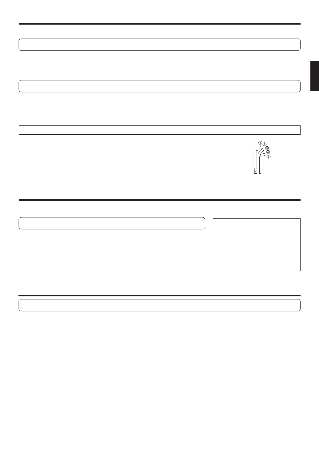
4
Indicator (Fig. 3)
5
Remote Control Signal Receiver
6
OPERATION Indicator Lamp (green)
7
TIMER Indicator Lamp (orange)
●
If the TIMER indicator lamp flashes when
the timer is operating, it indicates that a fault
has occurred with the timer setting (See
Page 16 Auto Restart).
8
ECONOMY Indicator Lamp (green)
9
Intake Grille (Fig. 4)
0
Front Panel
A
Air Filter
B
Airfl ow Direction Louver
C
Damper
D
Right-Left Louver
(behind Airflow Direction Louver and
Damper)
E
Drain Hose
F
Air Cleaning Filter
G
Rope
Fig. 5 Remote Controller
1
START/STOP button
2
MODE button
3
SET TEMP. (temperature) buttons
4
Remote controller display
5
POWERFUL button
6
MIN. HEAT button
7
Signal transmitter
8
FAN button
9
SWING button
0
SET button
A
SLEEP timer button
B
CANCEL button
C
RESET button
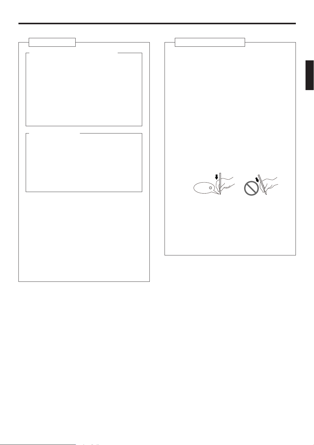
●
When you press the RESET button, press
it gently by using the tip of a ballpoint pen
or other small object in correct direction as
shown in this fi gure.
D
CLOCK ADJUST button
E
OFF timer button
F
ON timer button
G
SELECT button
H
ECONOMY button
I
°C / °F button
J
SWING display
RESET
9378532076_OM.indb 59378532076_OM.indb 5 9/24/2013 4:35:26 PM9/24/2013 4:35:26 PM
En-6
PREPARATION
Remote Controller Holder
CAUTION
●
If there is a curtain or a wall between the remote control and the receptor, the signal will not reach it.
●
When the receptor receives strong light, the air-conditioner may not operate correctly.Avoid direct exposure to sunlight, and keep the signal-
receiving part away from lights and fl at panel television screens.The signal may not be received in rooms with instantaneous fl uorescent lights
(such as inverter type ones). In such cases, please consult at the store where you purchased the product.
●
Please place the remote control in a place which will not be affected by heat from direct sunlight and home heaters.
●
Please do not apply strong shocks to the remote controller or pour water on it.
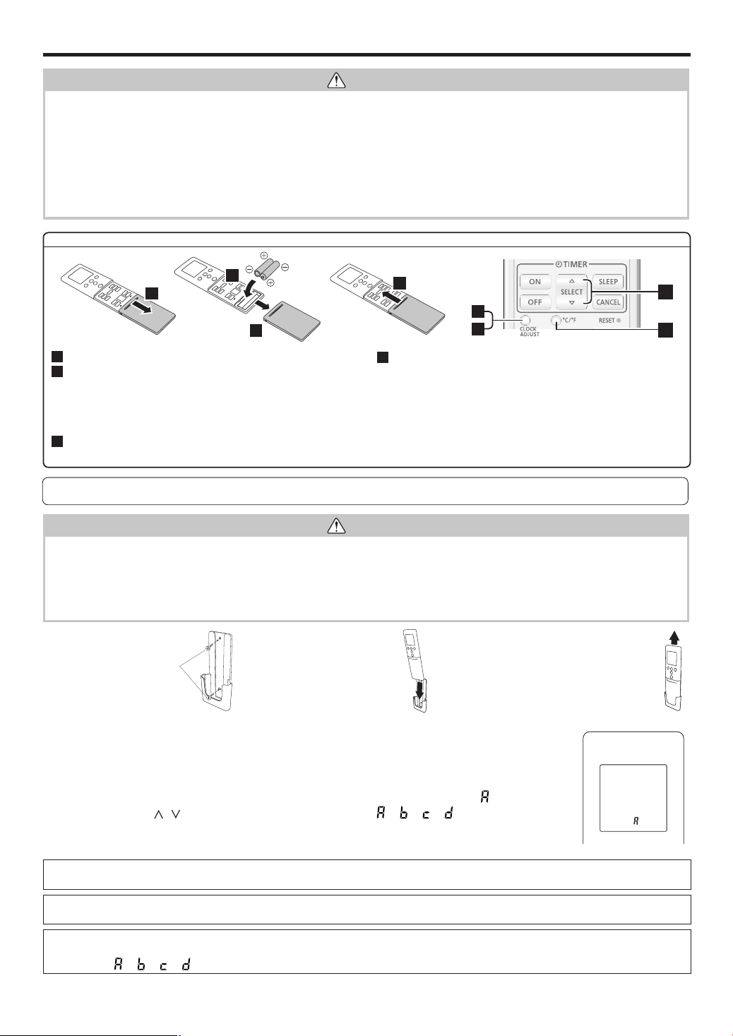
3 To remove the Remote Con-
troller (when use at hand).
1 Mount the Holder. 2 Set the Remote
Controller.
Screws
Insert
Press in
Slide up
Pull out
Remote controller custom code setting
Use the following steps to select the custom code of the remote controller.
(Note that the air conditioner cannot receive a custom code if the air conditioner has not been set for the custom code.)
1. Press the START/STOP button until only the clock is displayed on the remote controller display.
2. Press the MODE button for at least fi ve seconds to display the current custom code (initially set to
).
3. Press the SET TEMP. (
/ ) button to change the custom code between → → → .
Match the code on the display to the air conditioner custom code.
4. Press the MODE button again to return to the clock display. The custom code will be changed.
If no buttons are pressed within 30 seconds after the custom code is displayed, the system returns to the original clock display. In this case, start
again from step 1.
The air conditioner custom code is set to A prior to shipment.
Contact your retailer to change the custom code.
The remote controller resets to custom code A when the batteries in the remote controller are replaced. If you use a custom code other than
custom code A, reset the custom code after replacing the batteries. If you do not know the air conditioner custom code setting, try each of the
custom codes ( → → → ) until you fi nd the code which operates the air conditioner.
CAUTION
• To prevent malfunction or damage of the remote controller:
- Place remote controller at where will not be exposed to direct sunlight or excessive heat.
- Remove batteries if the product is not going to be used for an extended period.
- Exhausted batteries must be removed immediately, and be disposed according to the local laws and regulations of your region.
• If leaking battery fl uid comes in contact with your skin, eyes, or mouth, immediately rinse with plenty of clean water, and consult your physician.
• Obstacles such as a curtain or wall between the remote controller and the indoor unit may affect the appropriate signal transmission.
• Do not apply strong shocks to the remote controller.
• Do not pour water on the remote controller.
• Do not attempt to recharge dry batteries.
Battery (R03/LR03/AAA × 2) loading and remote controller preparation
1
4
2
3
5
7
6
8
5
Press CLOCK ADJUST button to start clock setting.
6
Set the time by pressing SELECT button.
Each time you press the button, the value increases or
decreases 1 minute. With pressing and holding the button, the
value increasesor decreases 10 minutes.
* By pressing the TEMP. (∧∨) buttons, the time indicator can be
changed from a 24-hour to a 12-hour clock.
7
Press the CLOCK ADJUST button again to complete the clock
setting.
8
Press the °F / °C button to select the preferred temperature unit.
(Factory setting is °F.)
Notes:
• Use specifi ed type of battery only.
• Do not use new battery and used battery together.
• Batteries can be used about 1 year in ordinary use.
• If the remote control range noticeably got shorten, replace the bat-
teries, and press RESET button.
9378532076_OM.indb 69378532076_OM.indb 6 9/24/2013 4:35:26 PM9/24/2013 4:35:26 PM
En-7
OPERATION
You can quickly start the operation with following 3 steps:
To Select Mode Operation
1
Press the START/STOP button (Fig.5
1
).
2
Press the MODE button (Fig.5
2
) to select the desired mode.
Switches operation mode in following order.
▲
▲
▲
▲
▲
AUTO COOL DRY FAN HEAT
Notes in HEAT mode:
• At the beginning of the operation, the indoor unit operates at very low fan speed for
about 3–5 minutes for preparation, and then switches to the selected fan speed.
• Automatic defrosting operation overrides the heating operation when it is necessary.
To Set the Temperature
Press the SET TEMP. button (Fig. 5
3
).
button: Press to raise the temperature setting.
button: Press to lower the temperature setting.
Set desired temperature.
In COOL/DRY mode, the value needs to be set at lower temperature than current room temperature, and in HEAT mode, the value needs to be set
at higher temperature than current room temperature. Otherwise, corresponding operation mode does not start to work.
Temperature setting range
AUTO/COOL/DRY 64-88 °F (18–30 °C)
HEAT 60-88 °F (16–30 °C)
*:Temperature control is not available in FAN mode.
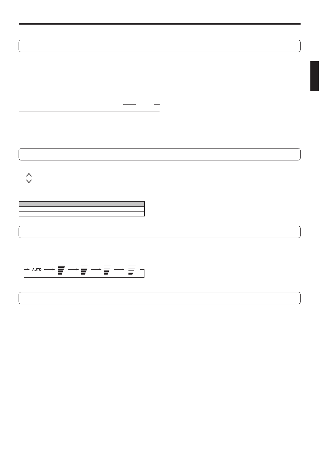
To Set the Fan Speed
Press the FAN button (Fig. 5
8
).
Each time the button is pressed, the fan speed changes in the following order:
Controls the fan speed.
(AUTO) (HIGH) (MED) (LOW) (QUIET)
• When AUTO is selected, the fan speed is automatically adjusted according to the operation mode.
SUPER QUIET Operation
SUPER QUIET operation begins. The indoor unit’s airfl ow will be reduced for quieter operation.
●
SUPER QUIET operation cannot be used during Dry mode. (The same is true when dry mode is selected during AUTO mode op-
eration.)
●
During Super Quiet operation, Heating and Cooling performance will be reduced somewhat. If the room does not warm up/ cool
down when using SUPER QUIET Operation, please adjust the air conditioner’s Fan Speed.
9378532076_OM.indb 79378532076_OM.indb 7 9/24/2013 4:35:27 PM9/24/2013 4:35:27 PM
En-8
To Stop Operation
Press the START/STOP button (Fig. 5
1
).
The OPERATION Indicator Lamp (green) (Fig. 3
6
) will go out.
About AUTO CHANGEOVER Operation
AUTO:
●
When AUTO CHANGEOVER operation fi rst selected, the fan will operate at very low speed for about a few minutes, during
which time the indoor unit detects the room conditions and selects the proper operation mode.
If the difference between temperature setting and actual room temperature is more than +4 °F (+2 °C)
Cooling or dry opera-
tion
If the difference between temperature setting and actual room temperature is within ±4 °F (±2 °C)
Determined by outdoor tem-
perature
If the difference between temperature setting and actual room temperature is more than -4 °F (-2 °C)
Heating operation
●
When the indoor unit has adjusted your room’s temperature to near the temperature setting, it will begin monitor operation. In the
monitor operation mode, the fan will operate at low speed. If the room temperature subsequently changes, the indoor unit will
once again select the appropriate operation (Heating, Cooling) to adjust the temperature to the value set in the temperature.
●
If the mode automatically selected by the indoor unit is not what you wish, select one of the mode operation (HEAT, COOL, DRY,
FAN).
OPERATION
TIMER OPERATION
During Heating:
Set the
temperature
to a temperature set-
ting that is higher than the present room
temperature. The Heating mode will not
operate if the
temperature
is set lower
than the actual room temperature.
During Cooling/Dry:
Set the
temperature
to a temperature
setting that is lower than the present room
temperature. The Cooling and Dry modes
will not operate if the
temperature
is set
higher than the actual room temperature (in
Cooling mode, the fan alone will operate).
During Fan:
You can not use the indoor unit to heat and
cool your room.
About Mode Operation
Heating:
●
Use to warm your room.
●
When Heating mode is selected, the indoor unit will operate at very low
fan speed for about 3 to 5 minutes, after which it will switch to the se-
lected fan setting. This period of time is provided to allow the indoor unit
to warm up before begin full operation.
●
When the outdoor temperature is very low, frost may form on the outdoor
unit, and its performance may be reduced. In order to remove such frost,
the air conditioner will automatically enter the defrost cycle from time to
time. During Automatic Defrosting operation, the OPERATION Indicator
Lamp will fl ash, and the Heat operation will be interrupted.
●
After the start of Heating operation, it takes some time before the room
gets warmer.
Cooling:
●
Use to cool your room.
Dry:
●
Use for gently cooling while dehumidifying your room.
●
You cannot heat the room during Dry mode.
●
During Dry mode, the indoor unit will operate at low speed; in order to ad-
just room humidity, the indoor unit’s fan may stop from time to time. Also,
the fan may operate at very low speed when adjusting room humidity.
●
The fan speed cannot be changed manually when Dry mode has been
selected.
Fan:
●
Use to circulate the air throughout your room.
Note for timer settings:
Any interruption of the power supply, such as a blackout or cutting off of a circuit breaker, makes
the set internal clock go wrong.
In such a case, the TIMER indicator on the indoor unit blinks, and you need to readjust the
setting.
9378532076_OM.indb 89378532076_OM.indb 8 9/24/2013 4:35:27 PM9/24/2013 4:35:27 PM
En-9
TIMER OPERATION
To Use the PROGRAM timer
You can set an integrated ON–OFF or OFF–ON timer. Either of the timer whose confi gured starting time is closer to the current time
works fi rst, and the order of timer operation is displayed as follows:
Timer Indicator on remote controller display
ON–OFF timer
OFF–ON timer
The timer that is set later starts counting down after the counting down of the preceding timer is fi nished.
Notes:
• If you change the setting value for the timer after the program timer is set, the counting down of the timer will be reset at that moment.
• Time setting for each combination should be within a span of 24 hours
.
To Use the SLEEP timer
1
Press the SLEEP timer button (Fig. 5
A
) to activate the SLEEP timer.
OPERATION indicator and TIMER indicator on the indoor unit turns on.
2
Adjust the time by pressing the SELECT button (Fig. 5
G
) within about 5 seconds,
while the clock indicator is blinking.
(About 5 seconds later, the remote controller display returns to standby screen.)
Each time you press the button, the time changes as follows:
9.07.05.03.02.01.00.5
hours(30 min.)
To repeat the timer, press the SLEEP timer button when indicator is not displayed on the remote controller display.
To help you to fall asleep comfortably and prevent excessive warming or cooling in sleep, the SLEEP timer controls the temperature
setting automatically in accordance with the set time shown as follows. The air conditioner completely turns off after the set time has
elapsed.
In HEAT mode
Set
temperature
Set time
1 hour
Set time
1 hour
1.5 hour
30 min.
2 °F (1 °C)
4 °F
(2 °C)
6 °F
(3 °C)
8 °F (4 °C)
4 °F
(2 °C)
2 °F (1 °C)
In COOL or DRY mode
To Use the ON timer or OFF timer
1
Turn on the indoor unit by pressing the START/STOP button. (Fig. 5
1
).
OPERATION indicator on the indoor unit turns on. If the indoor unit is already operating, skip this step.
2
Press the ON timer button (Fig. 5
F
) or the OFF timer button. (Fig. 5
E
).
Clock indicator on the remote controller display starts blinking, and TIMER indicator on the indoor unit turns on.
3
Adjust the time by pressing the SELECT button (Fig. 5
G
) within about 5 seconds,
while the clock indicator is blinking.
(About 5 seconds later, the remote controller display returns to standby screen.) To cancel the timer and return to the normal operation,
press the CANCEL button.To redo the timer setting, perform step 2 and 3.
9378532076_OM.indb 99378532076_OM.indb 9 9/24/2013 4:35:27 PM9/24/2013 4:35:27 PM
En-10
Vertical Air Direction Adjustment
WARNING
●
Never place fi ngers or foreign objects inside the outlet ports, since the internal fan operates at high speed and could cause personal injury.
●
Always use the Remote controller’s SET button to adjust the vertical airfl ow louvers. Attempting to move them manually could result in im-
proper operation; in this case, stop operation and restart. The louvers should begin to operate properly again.
●
When used in a room with infants, children, elderly or sick persons, the air direction and room temperature should be considered carefully
when making settings.
●
When indoor unit is embedded in a wall, airfl ow is fi xed to horizontal direction
5
.
Please ask the service personnel to perform the embedding in a wall.
Press the SET button (Fig. 5
<
).
Each time the button is pressed, the air direction range will change as follows:
1
2
3
4
5
The Remote controller’s display does
not change.
●
Use the air direction adjustments within the ranges shown above.
●
The vertical airfl ow direction is set automatically as shown, in accordance with the type of operation selected.
During Cooling/Dry mode : Upward fl ow
1
During Heating mode : Horizontal fl ow
4
●
During AUTO mode operation, for the fi rst minute after beginning operation, airfl ow will be upward
1
; the air direction cannot be
adjusted during this period.
●
During Heating mode operation, airfl ow will be upward
1
when the temperature of the air issued from the indoor is low.
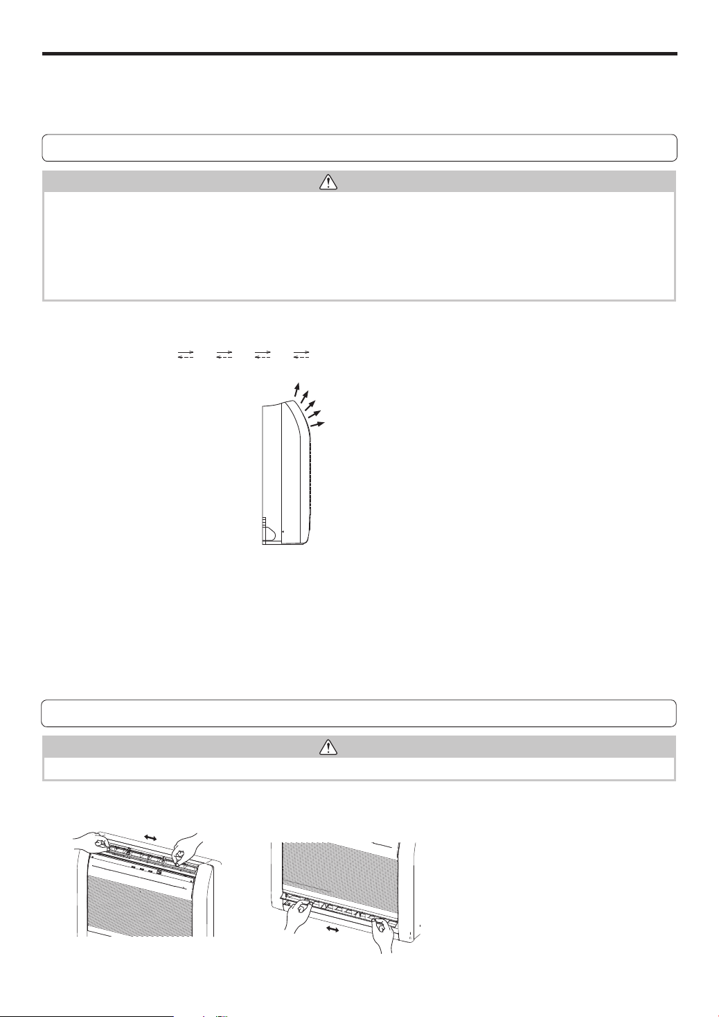
Right-Left Adjustment
WARNING
●
Always adjust the Right-Left louvers when the damper is open. Opening the damper forcibly with hands can cause damper of malfunction.
Adjust the Right-Left louvers.
●
Move the Right-Left louvers to adjust airfl ow in the direction you prefer.
ADJUSTING THE DIRECTION OF AIR CIRCULATION
Vertical (up-down) direction of airfl ow is adjusted by pressing the Remote controller’s SET button. Horizontal (right-left) airfl ow direc-
tion is adjusted manually, by moving the Airfl ow Direction Louvers.
Whenever making horizontal airfl ow adjustments, start air conditioner operation and be sure that the vertical air direction louvers are
stopped.
1
2
3
4
5
9378532076_OM.indb 109378532076_OM.indb 10 9/24/2013 4:35:27 PM9/24/2013 4:35:27 PM
En-11
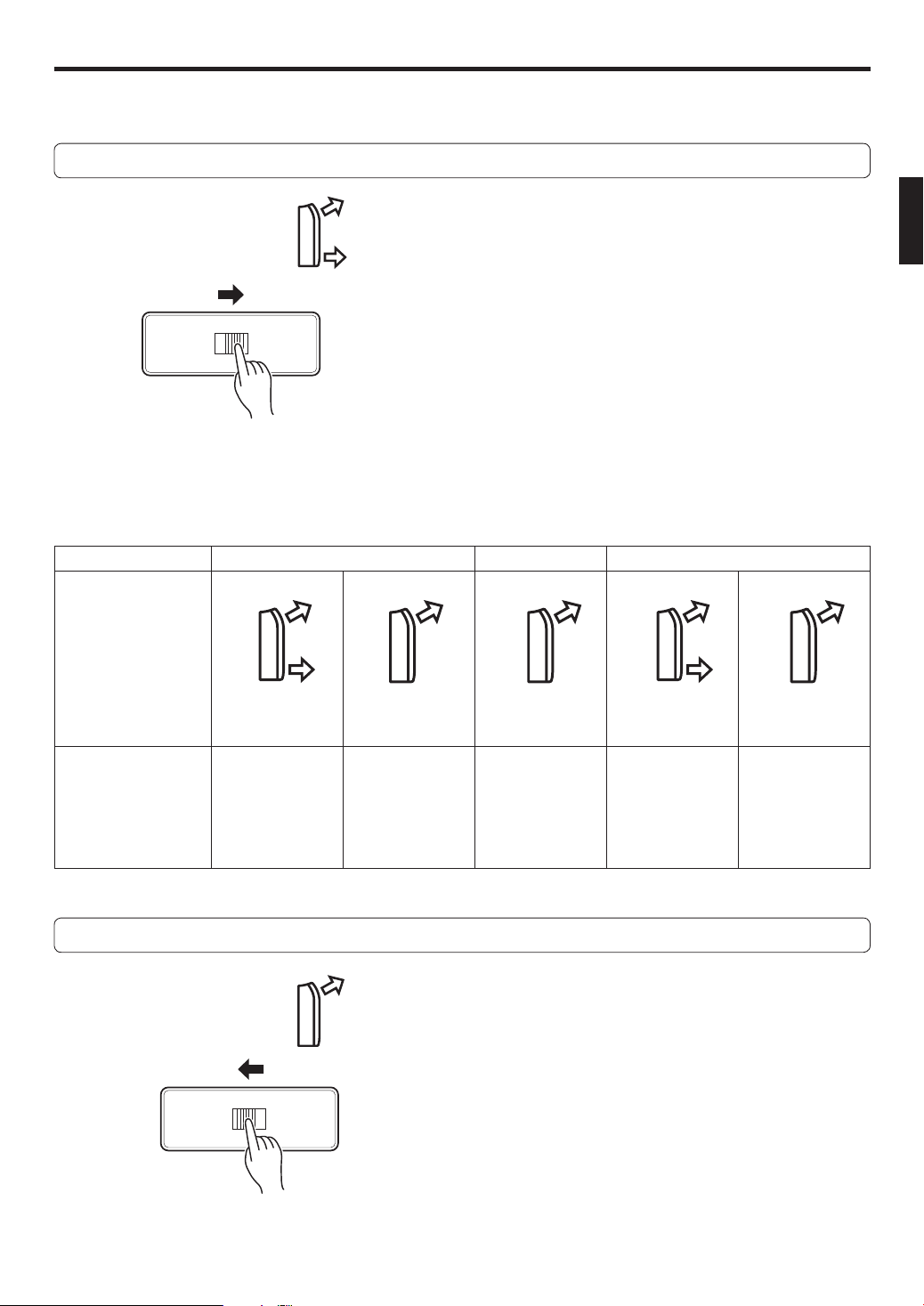
AIR OUTLET SELECTION
With this function , air come out simultaneously from the upper and lower air outlets so that the room can be cooled or heated effec-
tively. This function is set using the switch behind the front grille of the Indoor unit. (This function is available in cooling and heating
operation.)
How to set to blow out air from the upper and lower air outlets
■
Set the air outlet selection switch to
Air blows out automatically from the upper and lower air outlets as shown in the table below.
NOTE:
Set the air outlet selection switch to the end. Otherwise, air outlet cannot be selected as intended.
Description of operation
Operation COOLING Mode DRY Mode HEATING Mode
Airfl ow
Conditions
Upper and lower
airfl ow
Upper airfl ow Upper airfl ow only Upper and lower
airfl ow
Upper airfl ow
Room temperature
and set tempera-
ture are different.
Room tempera-
ture is close to set
temperature, or
the air conditioner
has operated for
1hour.
_
Airflow tempera-
ture is high.
Airflow tempera-
ture is low.
(During defrosting
operation, start of
operation, etc.)
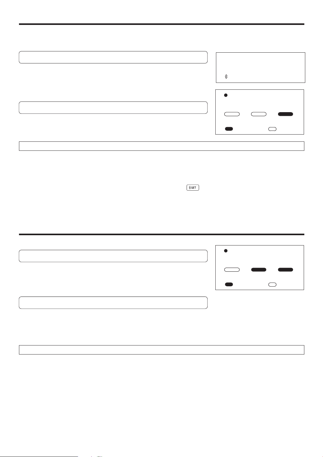
How to set to blow out air from the upper air outlet only
■
Set the air outlet selection switch to
9378532076_OM.indb 119378532076_OM.indb 11 9/24/2013 4:35:27 PM9/24/2013 4:35:27 PM
En-12
MIN. (MINIMUM) HEAT OPERATION
• The room temperature can be maintained at 50 °F (10 °C) by pressing the MIN. HEAT
button (Fig.5
6
) so as to prevent the room temperature from falling too far.
To use MIN. HEAT OPERATION
Press the MIN. HEAT button (Fig. 5
6
)
The OPERATION Indicator lamp (green)(Fig.3
6
) will go out, and the ECONOMY
Indicator lamp (green)(Fig. 3
8
) will light.
• The direction of airfl ow is set to horizontal.
To stop MIN. HEAT OPERATION
Press the START/STOP button (Fig. 5
1
)
Then the operation stops.
About the MIN. HEAT OPERATION
Starts MIN. HEAT operation that mainains the room temperature at 50 °F (10 °C) so as to prevent the room temperature to drop too
low.
When you press the button to start the MIN. HEAT operation, the indoor unit emits 2 short beeps and the ECONOMY indicator (green)
turns on.
Notes:
•
In MIN. HEAT operation mode, only vertical airfl ow direction can be adjusted by using button.
•
HEAT mode will not be performed if the room temperature is warm enough.
•
In multi-type air conditioning system, if other indoor unit is in HEAT mode, the temperature of the room where MIN. HEAT operation is performed
will rise. When performing MIN. HEAT operation, all the indoor units should be run in MIN. HEAT operation mode. To return to normal operation,
press the START/STOP button. The ECONOMY indicator turns off.
ECONOMY OPERATION
Begin Air Conditioner operation before performing this procedure.
To Use the ECONOMY Operation
Press the ECONOMY button (Fig.5
H
).
The OPERATION Indicator lamp (green)(Fig.3
6
) and the ECONOMY Indicator lamp
(green)(Fig.3
8
) will light.
Economy operation begins.
To Stop the ECONOMY Operation
Press the ECONOMY button (Fig.5
H
) again.
The ECONOMY Indicator lamp (green)(Fig.3
8
) will go out.
Normal operation begins.
About ECONOMY Operation
Starts or stops ECONOMY operation that saves more electricity consumption than the other operations with a conservative adjust-
ment of the room temperature. When you press the button, the ECONOMY indicator on the indoor unit turns on.
• In COOL or DRY mode, the room temperature will be adjusted at a few degree higher than the defi ned temperature.
In HEAT mode, the room temperature will be adjusted at a few degree lower than the defi ned temperature.
• Especially in COOL or DRY mode, you can have improved dehumidifi cation without signifi cantly lowering the room temperature.
Notes:
•
In COOL, HEAT, or DRY mode, the maximum output of this operation is approximately 70 % of usual air conditioning operation.
•
This operation cannot be performed during temperature monitoring by AUTO mode.
•
In multi-type air conditioning system, ECONOMY operation is performed only on the indoor unit whose ECONOMY button on the corresponding re-
mote controller is pressed.
Indicator Lamp
TIMER OPERATION ECONOMY
: Lighting : OFF
Indicator Lamp
TIMER OPERATION ECONOMY
: Lighting : OFF
While MIN. HEAT OPERATION is in
progress, only the following operation
can be used.
• SET
9378532076_OM.indb 129378532076_OM.indb 12 9/24/2013 4:35:27 PM9/24/2013 4:35:27 PM
En-13
SWING OPERATION
POWERFUL OPERATION
MANUAL AUTO OPERATION
Use the MANUAL AUTO operation in the event the Remote Controller is lost or otherwise unavailable.
How To Use the Main Unit Controls
The product will operate at maximum power, which is convenient when you want to
quickly cool down or warm up the room.
When you press the button to start the POWERFUL operation, the indoor unit emits 3
short beeps.
POWERFUL operation is automatically turned off in the following situations:
• Adjusted room temperature reached to the defi ned temperature in temperature setting
in COOL, DRY, or HEAT mode.
• 20 minutes have passed after fi nishing the POWERFUL operation mode setting. It is
not turned off automatically during setting of the POWERFUL operation.
How To Use the Main Unit Controls
Press the MANUAL AUTO button (Fig. 1
3
) more than 3 sec-
onds and less than 10 seconds on the main unit control panel.
To stop operation, press the MANUAL AUTO button (Fig. 1
3
) for 3 seconds.
●
When the air conditioner is operated with
the controls on the Main Unit, it will oper-
ate under the same mode as the AUTO
mode selected on the
Remote Control-
ler
(see page 6).
●
The fan speed selected will be “AUTO”
and the temperature setting will be stan-
dard. (76 °F (24 °C))
Begin air conditioner operation before performing this procedure.
To select SWING Operation
Press the SWING button (Fig. 5
9
).
The SWING Display (Fig. 5
J
) will light.
In this mode, the Airfl ow Direction Louvers will swing automatically to direct the airfl ow both up and down.
To stop SWING Operation
Press the SWING button (Fig. 5
9
) once again.
The SWING Display (Fig. 5
J
) will go out.
Airfl ow direction will return to the setting before swing was begun.
About Swing Operation
Swings between
1
and
5
.
• The SWING operation may stop temporarily when the air conditioner’s fan is not operating, or when
operating at very low speeds.
Notes:
• The airfl ow direction and the fan speed
are controlled automatically.
• This operation cannot be performed
simultaneously with ECONOMY
operation.
To return to normal operation, press the
button again. Then the indoor unit emits
2 short beeps.
9378532076_OM.indb 139378532076_OM.indb 13 9/24/2013 4:35:27 PM9/24/2013 4:35:27 PM
En-14
CLEANING AND CARE
CAUTION
●
Before cleaning the air conditioner, be sure to turn it off.
●
Be sure the Intake Grille (Fig. 1
9
) is installed securely.
●
When removing and replacing the air fi lter, be sure not to touch the heat exchanger, as personal injury may result.
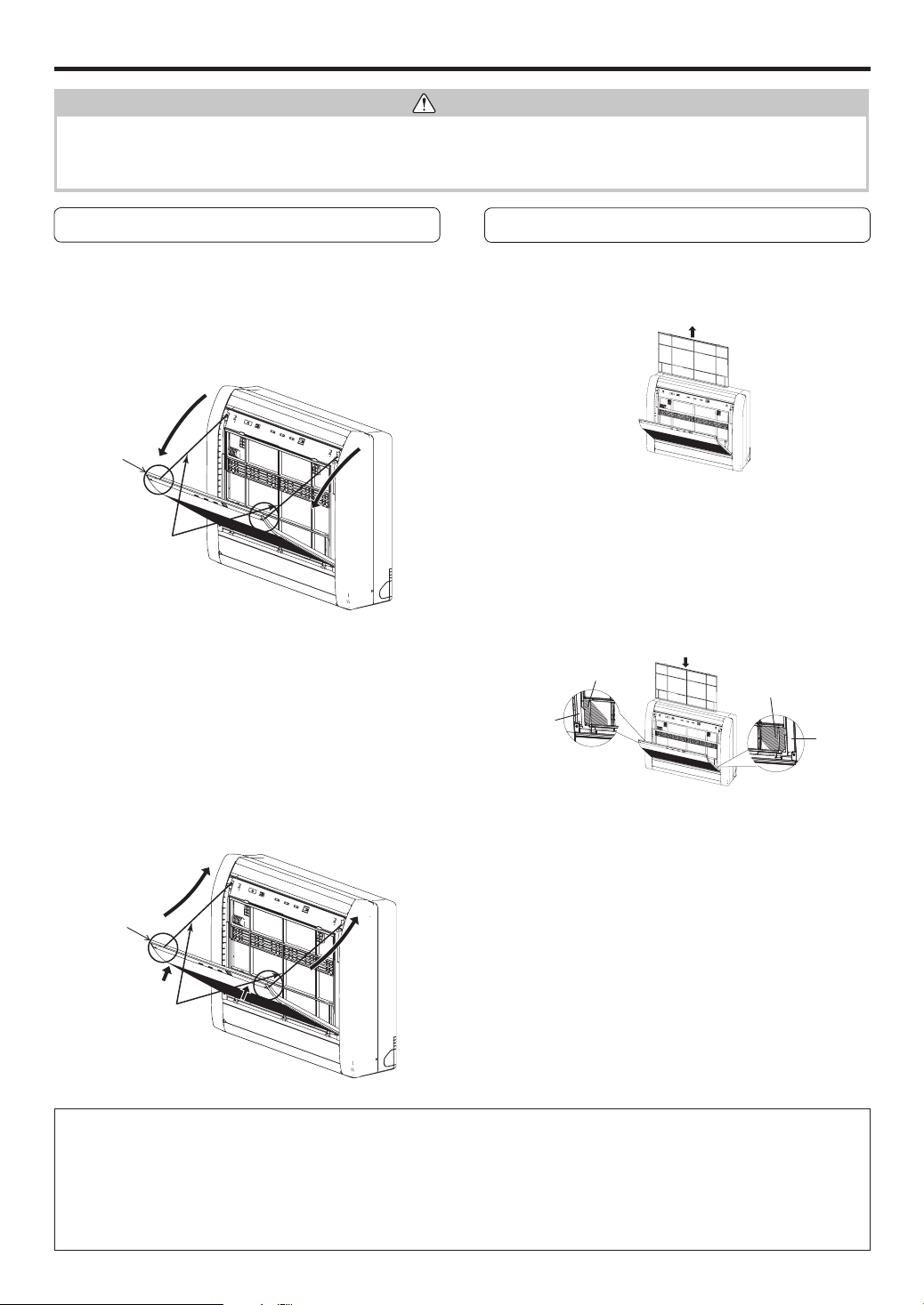
Cleaning the Intake Grille
1. Remove the Intake Grille.
1
Place your fi ngers at both top indicator of the grille pan-
el, and pull forward; if the grille seems to catch partway
through its movement, continue pulling down to remove.
2
Unhook the ropes which holds the grille.
2. Clean with water.
Remove dust with a vacuum cleaner; wipe the unit with
warm water, then dry with a clean, soft cloth.
3. Replace the Intake Grille.
1
Hook the ropes.
2
Set the left and right mounting shafts into the bearings
at the bottom of the panel.
3
Press the place where the mark on the diagram indi-
cates and close the Intake Grille.
Cleaning the Air Filter
1. Open the Intake Grille, and remove the
air fi lter.
Push down the air fi lter’s handle, disconnect the 2 upper
tabs, and pull out.
2. Remove dust with a vacuum cleaner or
by washing.
After washing, allow to dry thoroughly in a shaded place.
3. Replace the Air Filter and close the In-
take Grille.
1
Align the sides of the air fi lter with the panel, and push
in fully, making sure the 2 upper tabs are returned prop-
erly to their holes in the panel.
2
Close the Intake Grille.
●
Dust can be cleaned from the air fi lter either with a vacuum
cleaner, or by washing the fi lter in a solution of mild deter-
gent and warm water. If you wash the fi lter, be sure to allow
it to dry thoroughly in a shady place before reinstalling.
●
If dirt is allowed to accumulate on the air fi lter, airfl ow will be
reduced, lowering operating effi ciency and increasing noise.
●
During periods of normal use, the Air Filters should be
cleaned every 2 weeks.
●
When used for extended periods, the unit may accumulate dirt inside, reducing its performance. We recommend that the unit
be inspected regularly, in addition to your own cleaning and care. For more information, consult authorized service personnel.
●
When cleaning the unit’s body, do not use water hotter than 104 °F (40 °C), harsh abrasive cleansers, or volatile agents like
benzene or thinner.
●
Do not expose the unit body to liquid insecticides or hairsprays.
●
When shutting down the unit for 1 month or more, fi rst allow the fan mode to operate continuously for about one-half day to al-
low internal parts to dry thoroughly.
Rope
1
1
2
2
Intake
Grille
Intake
Grille
3
2
1
2
1
3
Rope
PANEL
AIR FILTER
AIR FILTER
PANEL
9378532076_OM.indb 149378532076_OM.indb 14 9/24/2013 4:35:27 PM9/24/2013 4:35:27 PM
En-15
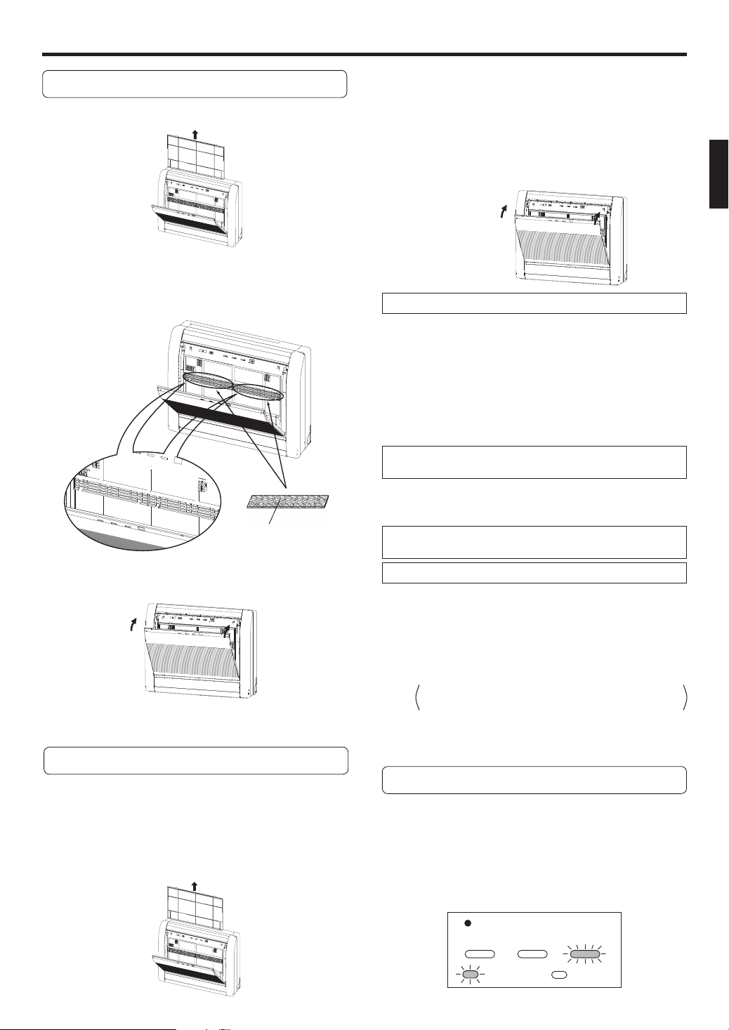
Air Cleaning Filter Installation
1. Open the Intake Grille and remove the Air
fi lter.
2. Install the Air cleaning fi lter set (set of 2).
Set the air cleaning fi lter into the panel.
Catch it on 5 places of picks.
(3 places of upper parts and lower part 2 places.)
3. Install the Air fi lter and close the Intake
Grille.
●
When air cleaning fi lters are used, the effect will increased
by setting the fan speed to “High”.
CLEANING AND CARE
2. Replace them by 2 new Air cleaning
fi lters.
1
Remove the old air cleaning fi lters in reverse order of
their installation.
2
Install in the same way as for installation of the air
cleaning fi lter set.
3. Install the Air fi lter and close the Intake
Grille.
In regard to the Air Cleaning Filters
POLYPHENOL CATECHIN AIR CLEANING FILTER (1 sheet)
●
The Air Cleaning Filters are disposable fi lters. (They can not
be washed and reused.)
●
For storage of the Air Cleaning Filters, use the filters as
soon as possible after the package has been opened.
(The air cleaning effect decreases when the fi lters are left in
the opened package)
●
Generally, the filters should be exchanged about every
3 months.
Please buy delicated air cleaning fi lters (UTR-FC03-2) (Sold
separately) to exchange the used dirty air cleaning fi lters.
[Negative air ions deodorizing fi lter (1 sheet) — light blue]
●
The fi lters should be exchanged about every 3 years so as
to maintain the deodorizing effect.
Please buy delicated deodorizing fi lter (UTR-FC03-3) (Sold
separately) when exchanging the fi lters.
Maintenance of Deodorizing Filters
In order to maintain the deodorizing effect, please clean the
fi lter in the follow way once 3 months.
1
Remove the deodorizing fi lter.
2
Clean with water and dry in the air.
1) Flush the fi lters with high-pressure hot water until the
surface of the fi lters are covered with water. Please
fl ush with diluent neutral detergent.
Never wash by reaming or rubbing, otherwise it
will damage the deodorizing effect.
2) Rinse with water fl ow.
3) Dry in shade.
3
Reinstall the deodorizing fi lter.
Replacing dirty Air cleaning fi lters
Replace fi lters with the following components (purchased sep-
arately).
●
POLYPHENOL CATECHIN AIR CLEANING FILTER : UTR-FC03-2
●
Negative air ions deodorizing fi lter: UTR-FC03-3
1. Open the Intake Grille and remove the Air
fi lter.
Filter Indicator Reset (The special setting)
Can be used if set correctly during installation.
Please consult authorized serviceman when using
this function
.
●
It lights on when it is time to clean the air fi lters.
Clean the fi lter referring to “CLEANING AND CARE”.
After cleaning, press the MANUAL AUTO button (Fig.2
3
)
for 2 seconds or less on the indoor unit.
Air cleaning fi lter
Indicator Lamp
TIMER OPERATION ECONOMY
: Flashing : OFF
9378532076_OM.indb 159378532076_OM.indb 15 9/24/2013 4:35:28 PM9/24/2013 4:35:28 PM
En-16
TROUBLESHOOTING
CAUTION
In the event of a malfunction (burning smell, etc.), immediately stop operation, turn off the electrical breaker or disconnect the
power supply plug, and consult authorized service personnel.
Merely turning off the unit’s power switch will not completely disconnect the unit from the power source. Always be sure to turn off
the electrical breaker or disconnect the power supply plug to ensure that power is completely off.
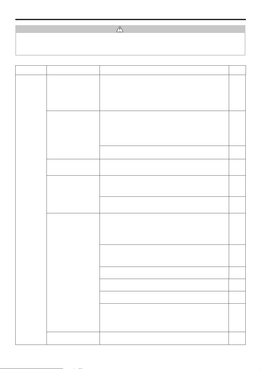
Before requesting service, perform the following checks:
Symptom Problem
See Page
NORMAL
FUNCTION
Doesn’t operate immedi-
ately:
●
If the unit is stopped and then immediately started again, the com-
pressor will not operate for about 3 minutes, in order to prevent fuse
blowouts.
●
Whenever the electrical breaker is turned off than on again or the
power supply plug is disconnected and then reconnected, the protec-
tion circuit will operate for about 3 minutes, preventing unit operation
during that period.
—
Noise is heard:
●
During operation and immediately after stopping the unit, the sound
of water fl owing in the air conditioner’s piping may be heard. Also,
noise may be particularly noticeable for about 2 to 3 minutes after
starting operation (sound of coolant fl owing).
●
During operation, a slight squeaking sound may be heard. This is
the result of minute expansion and contraction of the front panel due
to temperature changes.
—
●
During Heating operation, a sizzling sound may be heard occasional.
This sound is produced by the Automatic Defrosting operation.
18
Smells:
●
Some smell may be emitted from the indoor unit. This smell is the
result of room smells (furniture, tobacco, etc.) which have been
taken into the indoor unit.
—
Mist or steam are
emitted:
●
During Cooling or Dry operation, a thin mist may be seen emitted
from the indoor unit. This results from the sudden Cooling of room
air by the air emitted from the indoor unit, resulting in condensation
and misting.
—
●
During Heating operation, the outdoor unit’s fan may stop, and
steam may be seen rising from the unit. This is due to Automatic
Defrosting operation.
18
Airfl ow is weak or stops:
●
When Heating operation is started, fan speed is temporarily very
low, to allow internal parts to warm up.
●
During Heating operation, if the room temperature rises above the
temperature setting, the outdoor unit will stop, and the indoor unit
will operate at very low fan speed. If you wish to warm the room fur-
ther, set the temperature for a higher setting.
—
●
During Heating operation, the unit will temporarily stop operation
(for max. 15 minutes) as the Automatic Defrosting mode operates.
During Automatic Defrosting operation, the OPERATION Indicator
Lamp will fl ash.
18
●
The fan may operate at very low speed during Dry operation or
when the unit is monitoring the room’s temperature.
6 - 7
●
During SUPER QUIET operation, the fan will operate at very low
speed.
6
●
In the monitor AUTO operation, the fan will operate at very low
speed.
7
●
In case of Multi-type unit, if multiple units are operated in different
operation modes as shown below, the units operated afterward will
stop and the OPERATION indicator lamp (green) will fl ash.
Heating mode and cooling mode (or dry mode)
Heating mode and fan mode
19
Water is produced from the
outdoor unit:
●
During Heating operation, water may be produced from the outdoor
unit due to Automatic Defrosting operation.
18
9378532076_OM.indb 169378532076_OM.indb 16 9/24/2013 4:35:28 PM9/24/2013 4:35:28 PM
En-17
TROUBLESHOOTING
Symptom Problem
See Page
NORMAL
FUNCTION
The damper opens and
closes automatically
●
The damper is automatically controlled by a microcomputer accord-
ing to the airfl ow temperature and operation time of the air condi-
tioner.
—
Symptom Items to check
See Page
CHECK ONCE
MORE
Doesn’t operate at all:
●
Has the circuit breaker been turn off?
●
Has there been a power failure?
●
Has a fuse blown out, or a circuit breaker been tripped?
—
●
Is the timer operating? 8 - 9
Poor Cooling (or Heating)
performance:
●
Is the Air Filter dirty?
●
Are the air conditioner’s intake grille or outlet port blocked?
●
Did you adjust the room temperature settings (temperature) cor-
rectly?
●
Is there a window or door open?
●
In the case of Cooling operation, is a window allowing bright sunlight
to enter? (Close the curtains.)
●
In the case of Cooling operation, are there heating apparatus and
computers inside the room, or are there too many people in the
room?
●
Make sure the lower air outlet is not choked with foreign matters,
causing abnormal operation to damper.
—
●
Is the unit set for SUPER QUIET operation? 6
The unit operates
differently from the Remote
controller’s setting:
●
Are the Remote controller’s batteries dead?
●
Are the Remote controller’s batteries loaded properly?
5
If the problem persists after performing these checks, or if you notice burning smells, or the OPERATION Indicator Lamp (Fig. 3
6
)
and the TIMER Indicator Lamp (Fig. 3
7
) fl ashes, and ECONOMY Indicator Lamp (Fig.3
8
) fl ashes fast. Immediately stop opera-
tion, turn off the electrical breaker and consult authorized service personnel.
9378532076_OM.indb 179378532076_OM.indb 17 9/24/2013 4:35:28 PM9/24/2013 4:35:28 PM

En-18
OPERATING TIPS
Operation and Performance
Heating Performance
●
This air conditioner operates on the heat-pump principle,
absorbing heat from outdoor air and transferring that heat
indoors. As a result, the operating performance is reduced
as outdoor air temperature drops. If you feel that insuffi cient
heating performance is being produced, we recommend
you use this air conditioner in conjunction with another kind
of heating appliance.
●
Heat-pump air conditioners heat your entire room by recir-
culating air throughout the room, with the result that some
time may be required after fi rst starting the air conditioner
until the room is heated.
Microcomputer-controlled Automatic Defrosting
●
When using the Heating mode under conditions of low out-
door temperature and high humidity, frost may form on the
outdoor unit, resulting in reduced operating performance.
In order to prevent this kind of reduced performance, this
unit is equipped with a Microcomputer-controlled Automatic
Defrosting function. If frost forms, the air conditioner will
temporarily stop, and the defrosting circuit will operate brief-
ly (for max. 15 minutes).
During Automatic Defrosting operation, the OPERATION
Indicator Lamp (green) will fl ash.
●
After heating operation stops, if frost forms on the outdoor
unit, the unit will start Automatic Defrosting operation. At
this time, the outdoor unit will automatically stop after oper-
ating for a few minutes.
(However, some type of multi-type air conditioner doesn't
provide this function.)
AUTO Restart
In Event of Power Interruption
●
The air conditioner power has been interrupted by a power
failure. The air conditioner will then restart automatically in
its previous mode when the power is restored.
●
If a power failure occurs during TIMER operation, the timer will
be reset and the unit will begin (or stop) operation at the new
time setting. In the event that this kind of timer fault occurs the
TIMER Indicator Lamp will fl ash (see Page. 3).
●
Use of other electrical appliances (electric shaver, etc.) or
nearby use of a wireless radio transmitter may cause the air
conditioner to malfunction. In this event, temporarily discon-
nect the Power Supply Plug, reconnect it, and then use the
Remote Controller to resume operation.
9378532076_OM.indb 189378532076_OM.indb 18 9/24/2013 4:35:28 PM9/24/2013 4:35:28 PM

En-19
OPERATING TIPS
Notice
●
During use of the heating mode, the outdoor unit will occa-
sionally commence the defrost operation for brief periods.
During the defrosting operation, if the user sets the indoor
unit for heating again, the defrosting mode will continue,
and the heating operation will begin after completion of
defrosting, with the result that some time may be required
before warm air is emitted.
●
Operation can be done in the following different operating
modes.
Cooling mode and dry mode
Cooling mode and fan mode
Dry mode and fan mode
●
The operating mode (heating mode or cooling (dry) mode)
of the outdoor unit will be determined by the operating
mode of the indoor unit that was operated fi rst. If the in-
door unit was started in fan mode, the operating mode of
the outdoor unit will not be determined.
For example, if indoor unit (A) was started in fan mode
and then indoor unit (B) was then operated in heating
mode, indoor unit (A) would temporarily start operation
in fan mode but when indoor unit (B) started operating in
heating mode, the OPERATION indicator lamp (green) for
indoor unit (A) would begin to fl ash (1 second on, 1 sec-
ond off) and it would go into standby mode. Indoor unit (B)
would continue to operate in heating mode.
Simultaneous Use of Multiple Units
●
When using a multi-type air conditioner, the multiple indoor
units can be operated simultaneously, but when two or
more indoor units of the same group are operated simul-
taneously, the heating and cooling effi ciency will be less
than when a single indoor unit is used alone. Accordingly,
when you wish to use more than 1 indoor unit for cooling
at the same time, the use should be concentrated at night
and other times when less output is required. In the same
way, when multiple units are used simultaneously for heat-
ing, it is recommended that they be used in conjunction
with other auxiliary space heaters, as required.
●
Seasonal and outdoor temperature conditions, the struc-
ture of the rooms and the number of persons present may
also result in differences of operating effi ciency. We rec-
ommend that you try various operating patterns in order to
confi rm the level of heating and cooling output provided by
your units, and use the units in the way that best matches
your family’s lifestyle.
●
If you discover that one or more units delivers a low level
of cooling or heating during simultaneous operation, we
recommend that you stop simultaneous operation of the
multiple units.
●
Operation cannot be done in the following different operat-
ing modes.
If the indoor unit is instructed to do an operating mode that
it cannot perform, the OPERATION indicator lamp (green)
on the indoor unit will fl ash (1 second on, 1 second off)
and the unit will go into the standby mode.
Heating mode and cooling mode (or dry mode)
Heating mode and fan mode
●
During use of the heating mode, the top of the indoor unit
may become warm, but this is due to the fact that cool-
ant is circulated through the indoor unit even when it is
stopped; it is not a malfunction.
Multi-type Air conditioner
This indoor unit can be connected to a multi-type outdoor unit. The multi-type air conditioner allows multiple indoor units to be oper-
ated in multiple locations. The indoor units may be operated simultaneously, in accordance with their respective output.
9378532076_OM.indb 199378532076_OM.indb 19 9/24/2013 4:35:28 PM9/24/2013 4:35:28 PM