CONFIGURATION AND OPERATION MANUAL
SilverBack V
CAMERA-MOUNTABLE FIBER OPTIC TRANSMISSION SYSTEM
10 NEWTON PLACE
HAUPPAUGE, NY 11788 USA
(877) 685-8439 / (516) 671-7278 / FAX (516) 671-3362
www.multidyne.com
SilverBack V Camera-Mountable Fiber Optic Transmission System
© 2021 MultiDyne, Inc. Made in the USA Page
2
TABLE OF CONTENTS
TABLE OF CONTENTS __________________________________________________________________ 2!
IMPORTANT SAFETY INSTRUCTIONS _____________________________________________________ 4!
LASER SAFETY INFORMATION __________________________________________________________ 6!
OVERVIEW __________________________________________________________________________ 7!
SilverBack V Family ___________________________________________________________________ 7!
SilverBack V Camera Unit ______________________________________________________________ 7!
SilverBack V Base Unit _________________________________________________________________ 8!
INSTALLATION _______________________________________________________________________ 9!
Camera Unit Installation _______________________________________________________________ 9!
Base Unit Installation __________________________________________________________________ 9!
CONNECTIONS: BASE UNIT ____________________________________________________________ 12!
Camera Fiber Connectors _____________________________________________________________ 12!
SMPTE 304M LEMO Hybrid Fiber Connector Systems ___________________________________ 12!
Neutrik opticalCON DUO Hybrid Fiber Connector Systems _______________________________ 13!
ST Connector Systems ____________________________________________________________ 13!
ST & Molex Connector Systems ____________________________________________________ 14!
Signal I/O Connections _______________________________________________________________ 15!
4K Camera Video Connections _____________________________________________________ 15!
Secondary SDI Connections ________________________________________________________ 15!
Reference Sync Connections _______________________________________________________ 15!
Timecode Connections ___________________________________________________________ 15!

SilverBack V Camera-Mountable Fiber Optic Transmission System
© 2021 MultiDyne, Inc. Made in the USA Page
3
Camera Ethernet Connections _____________________________________________________ 16!
Intercom, Tally, and GPIO Connections ______________________________________________ 16!
Audio Connections ______________________________________________________________ 16!
Serial Data Connections __________________________________________________________ 17!
Frame Controller Connection ______________________________________________________ 17!
CONNECTIONS: CAMERA UNIT _________________________________________________________ 18!
Camera Unit Connectors ______________________________________________________________ 18!
4K Camera Video Connections _____________________________________________________ 18!
Camera Reference Sync Connections ________________________________________________ 19!
Timecode Connections ___________________________________________________________ 19!
Secondary SDI Connections ________________________________________________________ 19!
Built-in Viewfinder Switch _________________________________________________________ 19!
Ethernet Connection _____________________________________________________________ 20!
Intercom Headset Connection _____________________________________________________ 20!
Audio Connections ______________________________________________________________ 20!
Tally and GPIO Connections _______________________________________________________ 21!
Serial Data Connections __________________________________________________________ 21!
D-Tap Power Connections _________________________________________________________ 22!
CAMERA UNIT OPERATION ____________________________________________________________ 23!
Control Panel Indicators and Controls ___________________________________________________ 23!
Control Panel Navigation __________________________________________________________ 24!
CONTROL PANEL: STATUS SCREENS _____________________________________________________ 25!
General Instructions _________________________________________________________________ 25!
Status Screens ______________________________________________________________________ 25!
Home Screen ___________________________________________________________________ 25!
Optical Status Screen _____________________________________________________________ 26!
Power Status Screen _____________________________________________________________ 26!
CONTROL PANEL: CAMERA UNIT MENUS ________________________________________________ 27!
General Instructions _________________________________________________________________ 27!
Main Menu ________________________________________________________________________ 27!
Video Settings __________________________________________________________________ 27!
Audio Settings __________________________________________________________________ 29!
Serial Data Settings ______________________________________________________________ 34!
System Settings _________________________________________________________________ 34!
Saving and Recalling Settings __________________________________________________________ 37!
BASE UNIT OPERATION _______________________________________________________________ 38!
Front Panel Indicators and Controls _____________________________________________________ 38!
BASE UNIT MENUS __________________________________________________________________ 39!
General Instructions _________________________________________________________________ 39!
SBV System Status _______________________________________________________________ 39!
Base Unit Root Menu ____________________________________________________________ 39!
Gearbox Configuration and Operation _______________________________________________ 42!
Audio Input Configuration _________________________________________________________ 43!

SilverBack V Camera-Mountable Fiber Optic Transmission System
© 2021 MultiDyne, Inc. Made in the USA Page
4
Audio Output Configuration _______________________________________________________ 44!
Intercom Configuration ___________________________________________________________ 45!
Reference and Timecode Configuration ______________________________________________ 46!
Serial Data Configuration _________________________________________________________ 46!
Base Unit Network Configuration ___________________________________________________ 47!
IP Address Settings ______________________________________________________________ 47!
Firmware Updates _______________________________________________________________ 49!
Saving and Recalling Settings __________________________________________________________ 50!
APPENDIX A - TECHNICAL SPECIFICATIONS _______________________________________________ 51!
Connector Pinouts – Camera Unit _______________________________________________________ 54!
Connector Pinouts – Base Unit _________________________________________________________ 56!
APPENDIX B - TROUBLESHOOTING _____________________________________________________ 58!
Cable Cleaning Procedure _____________________________________________________________ 58!
APPENDIX C - Updating System software ________________________________________________ 60!
Overview __________________________________________________________________________ 60!
Base Unit Update Process _____________________________________________________________ 61!
Camera Unit Update Process ___________________________________________________________ 63!
IMPORTANT SAFETY INSTRUCTIONS
• Read these instructions.
• Keep these instructions.
• Heed all warnings.
• Follow all instructions.
• Do not use this apparatus near water.
• Clean only with dry cloth.
• Do not block any ventilation openings. Install in accordance with the manufacturer's
instructions.
• Do not install near any heat sources such as radiators, heat registers, stoves, or other apparatus
(including amplifiers) that produce heat.
• Do not defeat the safety purposes of the grounding-type plug. A ground-type plug has two
blades and a third grounding prong. The third prong is provided for your safety. If the provided
plug does not fit into your outlet, consult an electrician for replacement of the obsolete outlet.
• Protect the power cord from being walked on or pinching, particularly at plugs, convenience
receptacles, and points where they exit from the apparatus.
• Only use attachments/accessories specified by the manufacturer.
• Use only with the cart, stand, tripod, bracket, or table specified by the manufacturer, or sold
with the apparatus. When a cart is used, use caution when moving the cart/apparatus
combination to avoid injury from tip-over.
• Unplug this apparatus during lightning storms or when unused for long periods of time.
• Refer all servicing to qualified service personnel. Servicing is required when the apparatus has
been damaged in any way, such as a damaged power-supply cord or plug, liquid has been spilled
SilverBack V Camera-Mountable Fiber Optic Transmission System
© 2021 MultiDyne, Inc. Made in the USA Page
5
or objects have fallen into the apparatus, the apparatus has been exposed to rain or moisture,
does not operate normally, or has been dropped.
• Throughout this manual, a number of warning and caution notes may be presented to alert the
user to important safety or operating information. Please read and comply with any and all of
the following warning and caution notes:
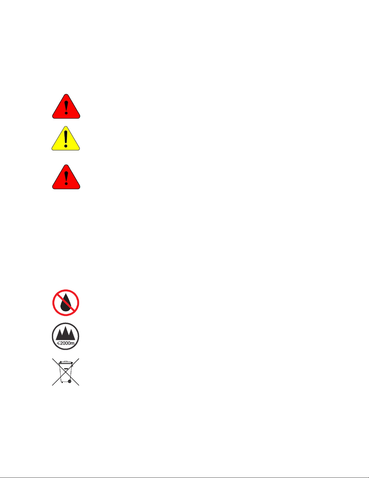
Warnings indicate danger that requires proper procedures or practices to prevent
injury or death to personnel.
Cautions indicate proper procedures or practices to prevent damage to equipment or
property.
Warning – The safe operation of this product requires that a protective earth
connection be provided. A grounding conductor in the equipment’s mains supply cord
provides this protective earth. To reduce the risk of electrical shock to the operator
and service personnel, this ground conductor must be connected to an earthed
ground. The mains plug shall remain readily operable.
• Always adhere to local building, safety and fire prevention codes during the installation and
operation of this product.
• Use only power cords specified for this product and certified for the country of use.
• Connect the unit only to a power source with the specified voltage rating.
• Connect the unit only to a power source with suitable surge suppression.
• Use only fuses of the type and rating specified.
• In case of an emergency ensure that power is disconnected.
Warning – The apparatus shall not be exposed to dripping or splashing, and no
objects filled with liquids, such as vases, shall be placed on the apparatus.
Warning – This symbol indicates that the apparatus should not be used at altitudes
exceeding 2000 m.
Warning – Waste Electrical and Electronic Equipment Directive (WEEE Directive) -
Please contact your local authority for further details of your nearest designated
collection point. Penalties may be applicable for incorrect disposal of this waste, in
accordance with your national legislation.
SilverBack V Camera-Mountable Fiber Optic Transmission System
© 2021 MultiDyne, Inc. Made in the USA Page
6
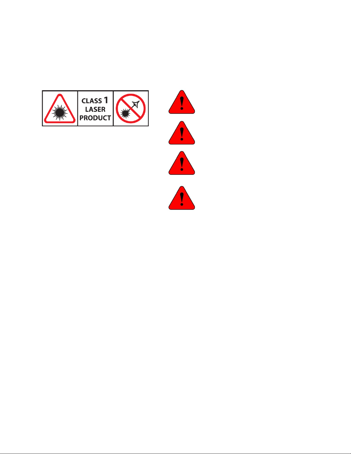
LASER SAFETY INFORMATION
This unit is classified as a CLASS 1 LASER PRODUCT according to EN60825-1 (EU) and FDA 21CFR 1040.10
(USA). Class 1 laser products are considered safe and do not result in biological hazard if used according
to these instructions.
Warning – Use of controls, adjustments, or
performance of procedures other than those
specified herein may result in hazardous
radiation exposure.
Warning – Never look directly into the end of
the optical fiber while either end of the
system is operating.
Warning – Never clean an optical fiber
connector on equipment or cable that is
carrying light.
Warning – Always use dust caps on fiber
optic connectors when cables are not
connected. This will protect the connector
from damage and accidental exposure of a
human eye to an operating laser.

SilverBack V Camera-Mountable Fiber Optic Transmission System
© 2021 MultiDyne, Inc. Made in the USA Page
7
OVERVIEW
The SilverBack
TM
V camera-mountable fiber optic transmission system provides a robust, full-bandwidth
link between any 12G, quad-link or dual-link 4K camera and your truck, OB van, control room, flypack, or
“video village” position. The system aggregates all of the signals needed for multi-camera 4K/UHD
production onto a single tactical or SMPTE hybrid fiber cable, ensuring robust, trouble-free connectivity
between a remote production and studio.
The SilverBack V can transport up to one 12G-SDI, two 6G-SDI, or four 3G-SDI signals from a camera to
its rack-mounted base station, with one return path. Full camera control is provided by the camera
manufacturer’s control panel via serial or a 10/100/GigE Ethernet path. Genlock, intercom, tally, and
audio paths are also provided. You can operate the unit using a hybrid cable which simultaneously
provides power to the camera, or you can use lightweight, robust tactical fiber and power the camera
locally.
SilverBack V Family
There are several models of SilverBack V, each with slightly different features and capabilities. Review
this chart to ensure that your model has the particular feature you require.
Feature
Signal Flow
Direction
SBV-
3EO
SBV-
3GX
SBV-
2X2
SBV-
3X3
SBV-
4K1
SBV-
4K2
SBV-
42
SBV-
44
Camera Base
Signal
Count
Signal
Count
Signal
Count
Signal
Count
Signal
Count
Signal
Count
Signal
Count
Signal
Count
UHD Gearbox
>
0
0
0
0
1
1
1
1
3G-SDI
>
1
1
2
3
1
2
0
0
3G-SDI
<
1
1
2
3
1
2
2
4
Reference
<
0
1
1
1
1
1
1
1
Timecode
< >
0
1
1
1
1
1
1
1
Audio
< >
0
4
4
4
4
4
4
4
Intercom
< >
0
2
2
2
2
2
2
2
Tally
<
0
2
2
2
2
2
2
2
GPIO
< >
0
1
1
1
1
1
1
1
Ethernet
< >
1
1
1
1
1
1
1
1
Serial Data
< >
0
2
2
2
2
2
2
2
SilverBack V Camera Unit
The SilverBack V camera unit connects to the camera's rear battery mount. The device's OLED display
provides clarity and easy access to configure system parameters, adjust intercom levels, and
troubleshoot.

SilverBack V Camera-Mountable Fiber Optic Transmission System
© 2021 MultiDyne, Inc. Made in the USA Page
8
SilverBack V Base Unit
The SilverBack V base unit interfaces up to two cameras and accessories via lightweight tactical fiber
cable or with SMPTE hybrid fiber cable to deliver all of your signals and the power to run your cameras
and accessories. Separate internal power supplies provide power for each camera chain, and there are
redundant power supplies for power within the base unit.
The base unit front panel’s simple interface lets the operator easily monitor system link and signal status
via a TFT display. Dedicated status LEDs permit easy monitoring of key signal levels, and a menu system
on the TFT display allows detailed status and configuration of system parameters.
SilverBack V Camera-Mountable Fiber Optic Transmission System
© 2021 MultiDyne, Inc. Made in the USA Page
9
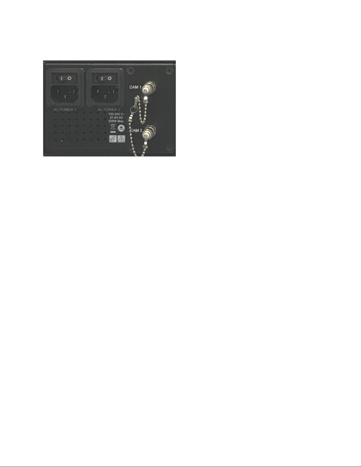
INSTALLATION
AC POWER 1: Camera 1 and base unit power
AC POWER 2: Camera 2 and base unit power
Camera Unit Installation
Connect the SilverBack V adapter unit to your camera's Anton Bauer or V-mount battery connector. Click
into place to ensure that the unit is secure.
Base Unit Installation
Before cabling, ensure that the SilverBack V base unit is clear of wiring, equipment, and other
obstructions. When mounting the base unit into a rack, allow at least 1 RU of open space above to
ensure proper cooling.
SilverBack V Camera-Mountable Fiber Optic Transmission System
© 2021 MultiDyne, Inc. Made in the USA Page
10
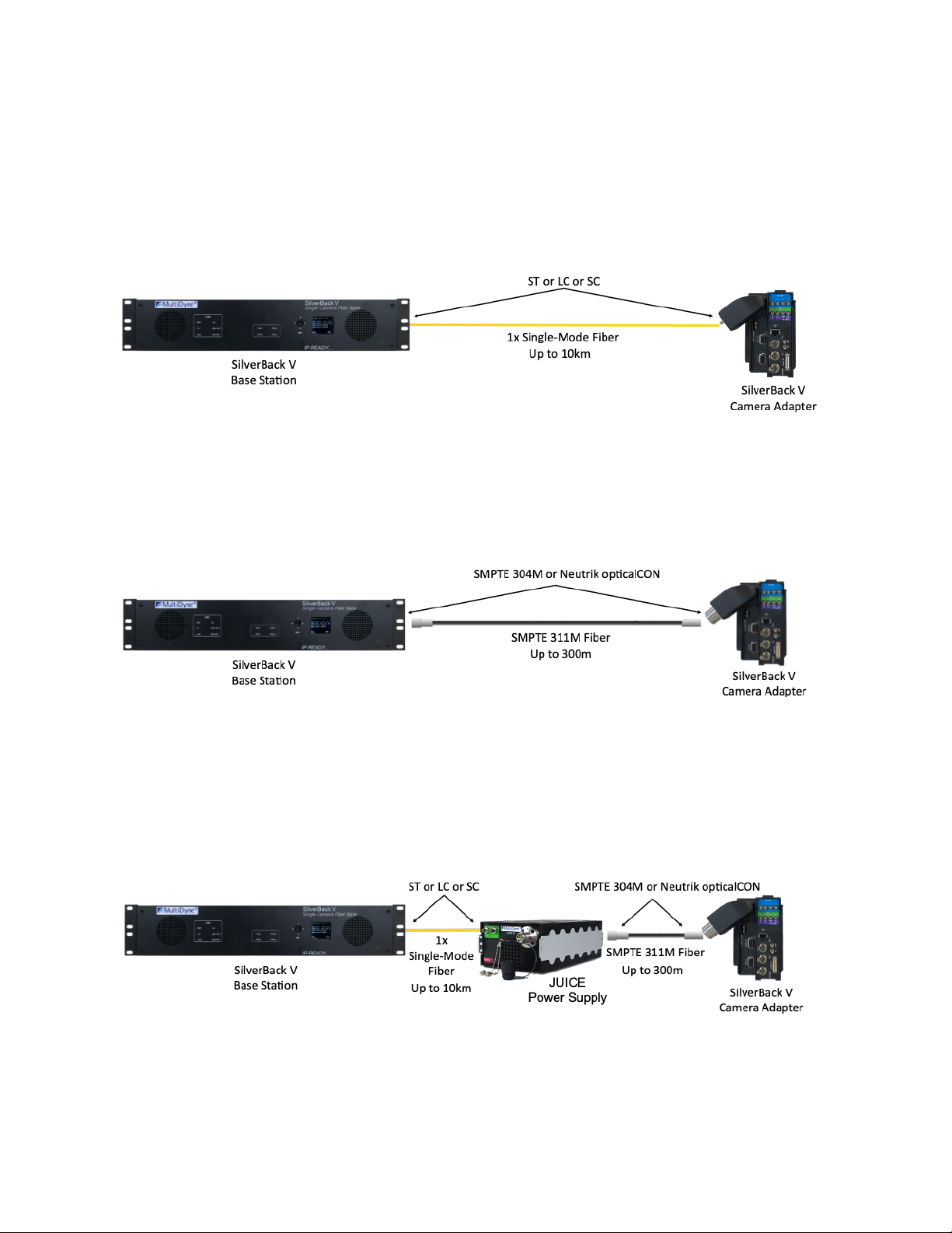
Integrating SilverBack V with Your Facility
A. Tactical Fiber Cable — Camera Powered Locally
B. SMPTE Hybrid Fiber — Standard Internal “Juice” Power Supply
C. SMPTE Hybrid Fiber — External “Juice-48 or Juice-60” Power Supply
SilverBack V Camera-Mountable Fiber Optic Transmission System
© 2021 MultiDyne, Inc. Made in the USA Page
11
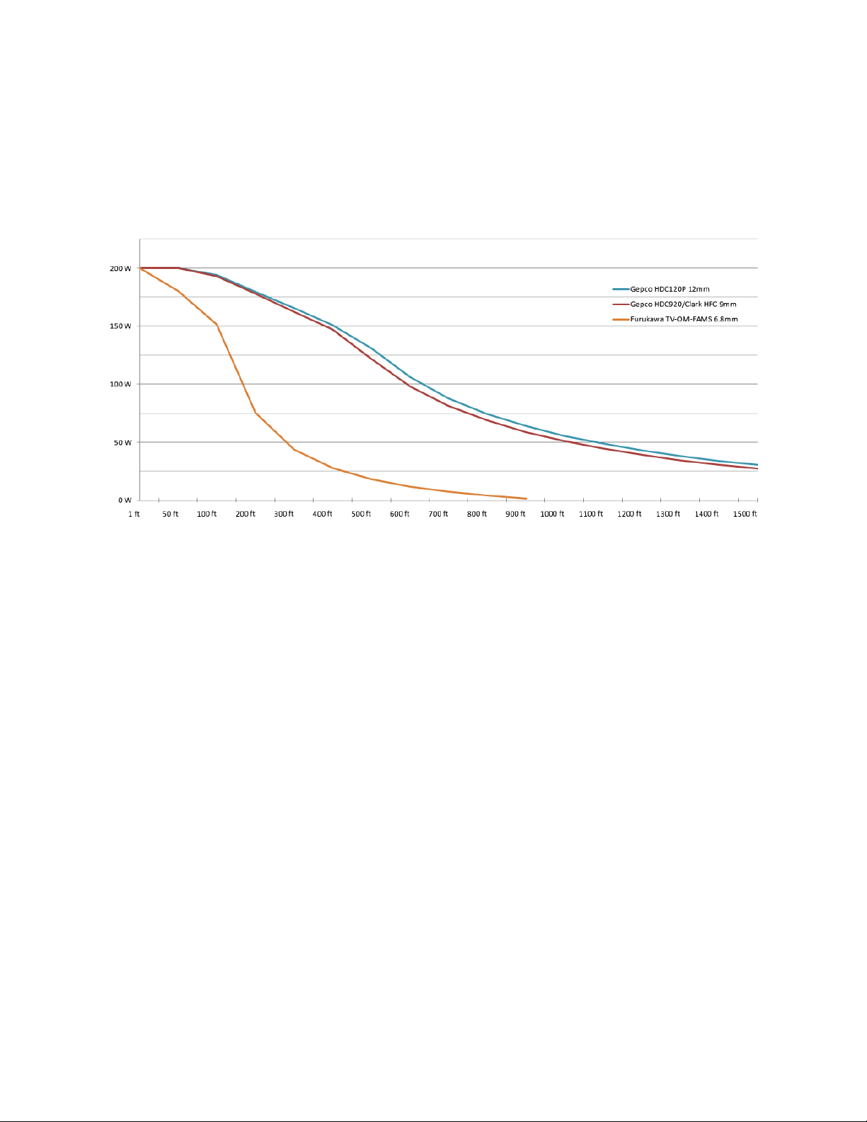
Maximum powered hybrid fiber distance varies and is determined by the size of the hybrid cable and the
overall system power requirements. Power consumption of the camera, viewfinder, lens, and any other
accessories will affect maximum available power at any given distance.
Hybrid Fiber Power vs. Distance
SilverBack V Camera-Mountable Fiber Optic Transmission System
© 2021 MultiDyne, Inc. Made in the USA Page
12
CONNECTIONS: BASE UNIT
The following section describes connections to the base unit. Depending on the type of SilverBack V
system ordered, some of the signal types may not be available.
Base Unit System Example: SB5-B4K1-SPPJ-UB2R-2
Camera Fiber Connectors
The SilverBack V base unit can be ordered with various types of fiber-optic connectors for interfacing
with the camera unit.
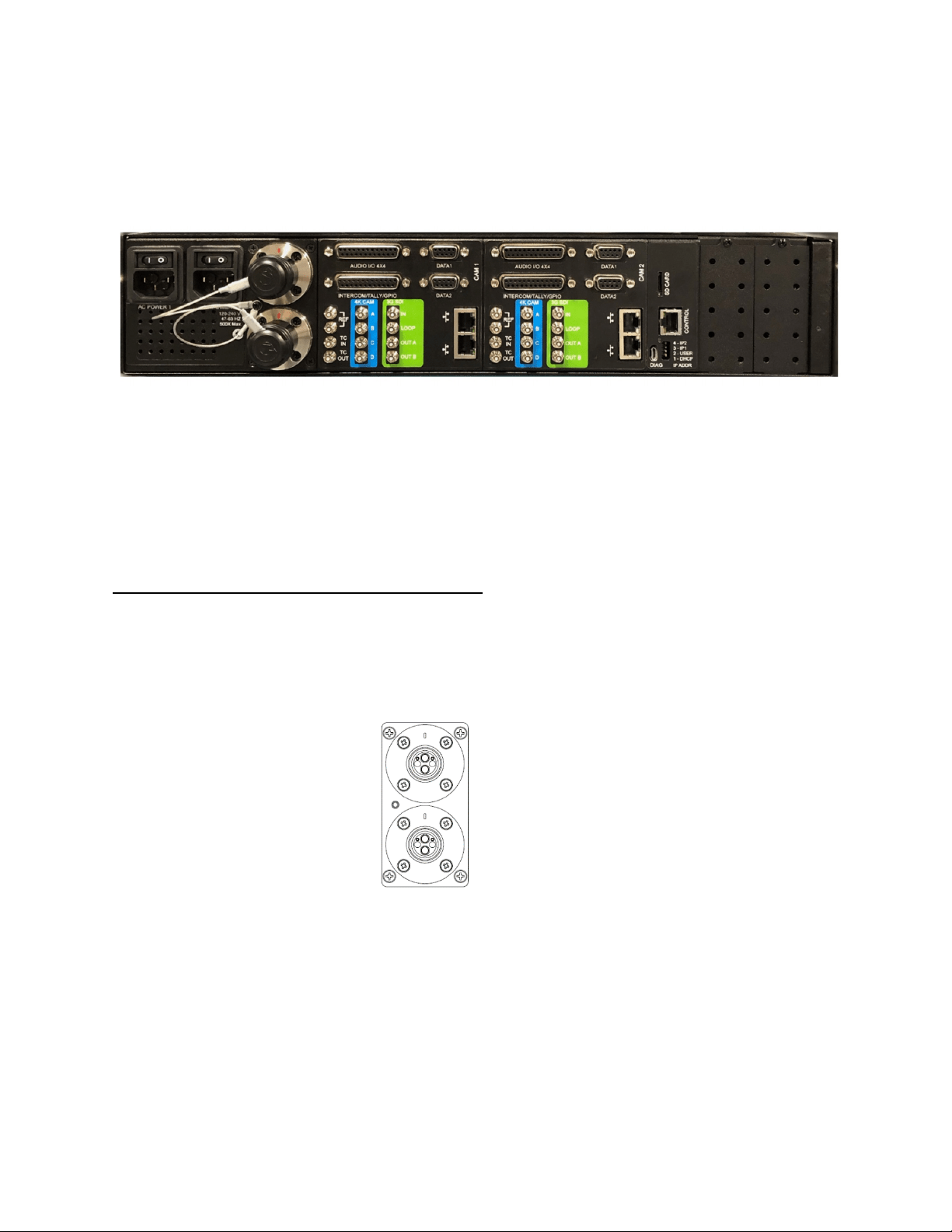
SMPTE 304M LEMO Hybrid Fiber Connector Systems
Systems with SMPTE 304M connectors typically provide both fiber-optic connectivity to the camera and
power to the camera system. Connect the camera units to these ports using SMPTE 311M cabling. It is
recommended to power off the base unit, where possible, before connecting hybrid fiber cable to the
camera unit.
Camera 1
Camera 2
SilverBack V Camera-Mountable Fiber Optic Transmission System
© 2021 MultiDyne, Inc. Made in the USA Page
13
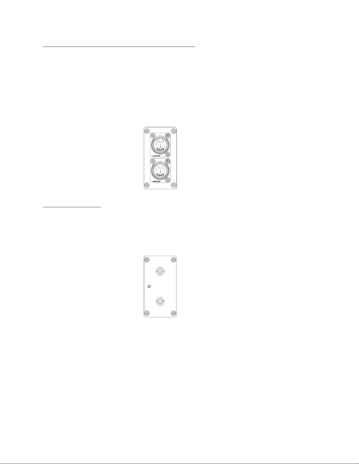
Neutrik opticalCON DUO Hybrid Fiber Connector Systems
Systems with Neutrik opticalCON DUO connectors typically provide both fiber-optic connectivity to the
camera and power to the SilverBack V camera unit. Connect the camera units to these ports using
opticalCON DUO cabling. It is recommended to power off the base unit, where possible, before
connecting hybrid fiber cable to the camera unit.
Base units without camera power are also available with OpticalCON DUO connectors. For these
systems, either opticalCON DUO cables or single-mode fiber (tactical) with LC/UPC connectors may be
used.
Camera 1
Camera 2
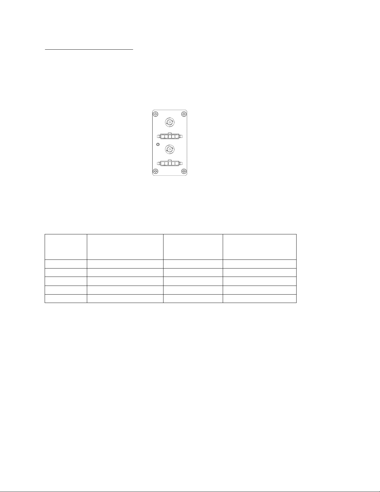
ST Connector Systems
Systems with ST fiber connectors do not provide power to the SilverBack V camera unit. Connect the
camera units to these ports using ST/UPC single-mode fiber (tactical). Power for the camera units must
be provided locally at the camera or by using a “juice” power supply and hybrid-fiber cabling on the final
fiber run to the camera.
Camera 1
Camera 2
SilverBack V Camera-Mountable Fiber Optic Transmission System
© 2021 MultiDyne, Inc. Made in the USA Page
14
ST & Molex Connector Systems
Systems with ST and Molex connectors provide both fiber-optic connectivity to the camera and power to
the SilverBack V camera unit. This configuration allows for custom breakout wiring and is typically used
where multiple systems are connected to a local patch panel, where they make the transition to
standard hybrid-fiber cabling. It is recommended to power off the base unit, where possible, before
connecting hybrid fiber cable to the camera unit.
Camera 1
Camera 2
The Molex connector on the SilverBack V chassis is a five-pin male Molex Mini-Fit Jr p/n 39-01-4053
(MDCON04787) or equivalent. This configuration requires Molex p/n 39-00-0041 (MDCON04799) crimp
pins. The mate for the chassis connector on a breakout cable is Molex Mini-Fit Jr p/n 39-01-4051
(MDCON04818) or equivalent. This configuration requires Molex p/n 39-00-0039 (MDCON04817) crimp
pins.
Molex Pin #
Description
Neutrik
OpticalCON DUO
Connector Pin #
Lemo
SMPTE Connector Pin
Color
1
54VDC Out +
4
Black
2
54VDC Out +
2
Red
3
Chassis Ground (Shield)
Tab
Green (Shield)
4
54VDC Out –
3
Grey
5
54VDC Out –
1
White

SilverBack V Camera-Mountable Fiber Optic Transmission System
© 2021 MultiDyne, Inc. Made in the USA Page
15
Signal I/O Connections
4K Camera Video Connections
The 4K CAM outputs on the base unit are highlighted in blue and are capable of outputting single-link,
dual-link, and quad-link SDI formats, supporting SD, HD, and 4K resolutions up to 4Kp60. Connect the 4K
CAM outputs of the base unit to the desired facility destination. Depending on the type of camera and
video resolution, up to four HD-BNC cables may be needed.
HDBNC
#
Signal
4K Application
1
12G/6G/3G/1.5G with gearbox
Single Link
Dual Link
Quad Link
2
6G/3G/1.5G with gearbox
X
3
3G/1.5G with gearbox
X
4
3G/1.5G with gearbox
The base unit video settings will need to be set to match the camera's output video format. Please refer
to the configuration and operations section for more information.
Secondary SDI Connections
The SilverBack V base unit is equipped with one or more secondary SDI paths, which function as camera
sends, returns, or both. These SDI connections only support data rates up to 3G (they are not 6G or 12G
capable).
The number of secondary SDI connections on the base unit and their directions varies from model to
model. These secondary SDI connections on the base unit are highlighted in green, and the label
indicates their direction.
Reference Sync Connections
Each camera chain in the SilverBack V base unit has a dedicated reference sync input. Connect the
desired sync reference to these ports. This REF input can accept an analog NTSC, PAL, or HD tri-level
signal. On older units, these inputs are loop-thru and require a 75-ohm termination on the loop-thru
connector or at the end of the loop. Current units are internally terminating and do not require external
termination.
If the camera requires SDI reference, use one of the 3G-SDI return inputs on each of the camera chains
of the base unit.
Timecode Connections
Each camera chain in the SilverBack V base unit has dedicated timecode inputs and outputs. Connect
timecode inputs and outputs to these ports, as necessary. Note that in order for a camera chain in the
base unit to output the camera’s timecode, the direction of the timecode connector on the camera unit
must be set as an input.

SilverBack V Camera-Mountable Fiber Optic Transmission System
© 2021 MultiDyne, Inc. Made in the USA Page
16
Camera Ethernet Connections
Each camera chain in the SilverBack base unit has a dedicated Ethernet path for the camera unit. These
paths are capable of 10/100/1000 Mbps operation and each contains an internal Ethernet switch,
providing two ports for connectivity at the base station. The use of Cat5e or Cat6 cables is
recommended.
Intercom, Tally, and GPIO Connections
Each camera chain in the SilverBack V base unit has a dedicated DB25 connector for intercom, tally, and
GPIO connections. This connector follows the standard pinout used by Sony and Panasonic CCUs and
supports 2-wire or 4-wire intercom systems.
Red and green tallies, as well as a GPIO in each direction, are provided. Tallies and GPIs expect a contact-
closure to ground to activate, and the GPO provides a contact-closure to ground when activated at the
camera unit. See pinouts for more details. Pre-made breakout cables are available for 2-wire and 4-wire
intercom systems.
Part Number
Description
BO-4WICTAL-SB5-1M
SilverBack V base station 4-Wire intercom and tally breakout cable
BO-RTS2W-ICTAL-SB5-1M
SilverBack V base station 2-Wire RTS intercom and tally breakout cable
BO-CC2W-ICTAL-SB5-1M
SilverBack V base station 2-Wire ClearCom intercom and tally breakout
cable
Audio Connections
Each camera chain in the SilverBack base unit has a dedicated DB25 connector, providing a bidirectional
four-channel audio interface with the camera. These inputs and outputs may be configured as either
analog line level or AES on a stereo-pair basis using the System menu.
The audio DB25 connector follows the Tascam channel-numbering convention, designating the first four
channels as audio inputs and the last four channels as audio outputs. When using AES, only the odd
numbered channels are used. See pinouts for more details. A pre-made breakout cable to XLR
connectors is available.
Part Number
Description
BO-TASCAM4X4- XLR-10F
DB25M to 4 XLR-3F and 4 XLR3-M, 10 ft.

SilverBack V Camera-Mountable Fiber Optic Transmission System
© 2021 MultiDyne, Inc. Made in the USA Page
17
Serial Data Connections
Each camera chain in the SilverBack base unit is equipped with two dedicated user-configurable serial
data ports to control cameras or other peripherals. These DB-9 serial data ports support RS232, RS422,
LANC, and TTL level data. See pinouts for more details. Pre-made cables for specific camera and RCP
manufacturers are available.
Part Number
Description
MDCAB00160
Cable Assembly, SilverBack V, base station-side RCP, for Sony 8-pin. 10'
long, DB9 male to Hirose MXR series 8-pin male.
MDCAB00180
Cable Assembly, SilverBack V, base station-side RCP, for Panasonic 10-
pin. 10' long, DB9 male to Hirose HR10A series 10-pin female.
MDCAB01068
Cable Assembly, SilverBack V, base station-side RCP, for Cannon LANC
RCP. 10' long, DB9 male to 3.5mm male plug.
MDCAB01256
Cable Assembly, SilverBack V, base station-side RCP, for Sony FS9
LANC. 10' long, DB9 male to 2.5mm female jack.
Frame Controller Connection
The frame controller in the SilverBack V base unit can be accessed via its 10/100 Mbps Ethernet port.
Connect this port to your facility network using Cat5e/Cat6 cabling.
The exact steps for connecting to your facility via an Ethernet network depends on the network
requirements of your facility. Contact your IT department before connecting to your facility network to
ensure that there are no IP address conflicts.
SilverBack V Camera-Mountable Fiber Optic Transmission System
© 2021 MultiDyne, Inc. Made in the USA Page
18
CONNECTIONS: CAMERA UNIT
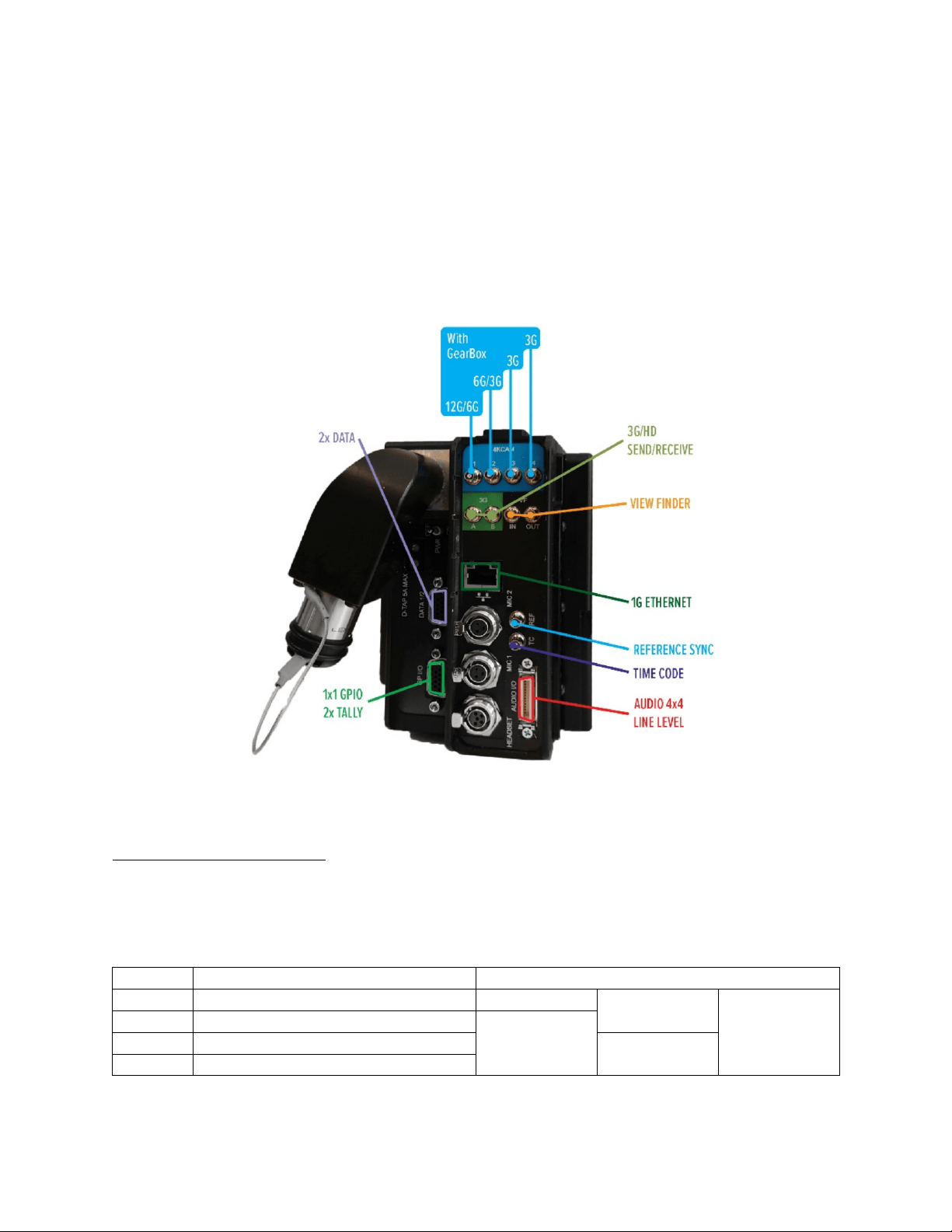
Camera Unit Connectors
The following section describes connections to the SilverBack V camera unit. Depending on the type of
system ordered, some of the signal types may not be available. The SilverBack V camera unit is installed
on the camera by sliding it onto the camera’s V-mount or Anton Bauer battery plate until it clicks and
locks into place.
Camera Unit System Example: SB5-C4K1-SPPJ-5CVV
4K Camera Video Connections
The 4K CAM inputs on the camera unit are highlighted in blue and are capable of accepting single-link,
dual-link, and quad-link SDI formats, supporting SD, HD, and 4K resolutions up to 4Kp60. Connect the 4K
CAM inputs of the camera unit to the camera’s 4K video outputs. Depending on the type of camera and
video resolution, up to four HD-BNC cables may be needed.
HDBNC #
Signal
4K Application
1
12G/6G/3G/1.5G with gearbox
Single Link
Dual Link
Quad Link
2
6G/3G/1.5G with gearbox
X
3
3G/1.5G with gearbox
X
4
3G/1.5G with gearbox

SilverBack V Camera-Mountable Fiber Optic Transmission System
© 2021 MultiDyne, Inc. Made in the USA Page
19
The camera unit video settings will need to be set to match the camera's output video format. Please
refer to the Configuration and Operations section of this manual for more information.
Camera Reference Sync Connections
Connect the SilverBack V camera unit REF output to camera REF/SYNC input using a BNC to HD-BNC
cable. A valid analog black burst or tri-level signal must be connected to the base unit REF input to
provide this reference signal to the camera.
If the camera requires SDI reference, connect one of the 3G SDI return outputs on the SilverBack V
camera unit to the REF input on the camera. A valid SDI signal must be connected to the base unit on
this return path to provide this SDI reference to the camera.
Timecode Connections
The SilverBack V camera unit has a single HDBNC connector for timecode, and the port direction is
configured as either an input or output in the system menus. Connect the timecode connector on the
SilverBack V camera unit to the appropriate timecode connector on the camera based on the desired
workflow.
Some cameras utilize a single connector for timecode. In this case, ensure that the timecode port
direction on the camera is set accordingly.
Secondary SDI Connections
The SilverBack V camera unit is equipped with one or more secondary SDI paths, which function as
camera sends, returns, or both. These SDI connections only support data rates up to 3G (they are not 6G
or 12G capable).
The number of secondary SDI connections on the camera unit and their directions varies from model to
model. These secondary SDI connections on the camera unit are highlighted in green and the label
indicates their direction. On certain models, some of the secondary SDI connections can be re-assigned
in the settings menu to connect to a built-in internal viewfinder switch.
Built-in Viewfinder Switch
On certain SilverBack V camera unit models, some of the secondary SDI connections can be re-assigned
in the Settings menu to connect to a built-in internal viewfinder switch. The camera unit configurations
that support a built-in viewfinder switch are shown in the table below.
Configuration
C3EO
C3GX
C2X2
C4K1
C4K2
C42R
C44R
C3X3
Viewfinder Switch
Yes
Yes
Yes
Yes
Yes
Yes
Yes
Yes
There are three types of 3G-SDI cards that can be installed in internal card slots: 2Tx, 2Rx, and TRx.
Typically, a VF-capable card is installed in the slot closest to the Ethernet or audio connectors. VF mode
port connections are highlighted in magenta on the label. Use the Video Settings menu to enable the
viewfinder switch and choose the card slot to assign it to.

SilverBack V Camera-Mountable Fiber Optic Transmission System
© 2021 MultiDyne, Inc. Made in the USA Page
20
TRX
Card
Viewfinder Mode Disabled
Viewfinder Mode Enabled
BNC #
Port
Name
Port Description
Port
Name
Port Description
1
3G IN
3G-SDI video input
3G IN
3G-SDI video input
2
LOOP
Loop output of above input
3G OUT
Return video from the base unit
3
3G OUT A
Return video from the base
unit
CAM IN
3G-SDI camera video input
4
3G OUT B
Return video from the base
unit (copy)
VF OUT
Viewfinder switch output.
Connect to SDI input of
viewfinder monitor
2RX
Card
Viewfinder Mode Disabled
Viewfinder Mode Enabled
BNC #
Port Name
Port Description
Port
Name
Port Description
1
3G OUT1 A
Return video 1 from the base
unit
3G OUT1
Return video 1 from the base unit
2
3G OUT1 B
Return video 1 from the base
unit (copy)
3G OUT2
Return video 2 from the base unit
3
3G OUT2 A
Return video 2 from the base
unit
CAM IN
3G-SDI camera video input
4
3G OUT3 B
Return video 2 from the base
unit (copy)
VF OUT
Viewfinder switch output.
Connect to SDI input of
viewfinder monitor
Ethernet Connection
The SilverBack V camera unit is equipped with a 10/100/1000 Mbps Ethernet port. Connect to the
camera or other device using Cat 5e or Cat 6 cable.
Intercom Headset Connection
The SilverBack V camera unit is equipped with an intercom headset port supporting both single- and
dual-muff intercom headsets via a 5-pin miniXLR connector. A 5-pin miniXLR-M to XLR-F adapter cable
for dual-muff headsets is included with the system. Contact MultiDyne for other adapter cable options.
Audio Connections
There are two distinct audio connection sections on the SilverBack V camera unit. The first are the two
miniXLR MIC/Line inputs adjacent to the intercom headset connector. These analog inputs are used for
applications requiring MIC level or the flexibility of switching between MIC and Line level. These inputs
are setup in the System menu. Gain is fixed at unity when set to Line mode. In MIC mode, gain is
adjustable and 48V phantom power can be enabled. Two 3-pin miniXLR-M to XLR-F adapter cables are
included with the system.
The other audio connector is a high-density 26-pin MDR connector. This provides bidirectional four-
channel analog Line/AES connectivity, mimicking the DB25 on the base unit. These inputs and outputs
are configured using the System menu as either analog Line level or AES, on a stereo-pair basis.

SilverBack V Camera-Mountable Fiber Optic Transmission System
© 2021 MultiDyne, Inc. Made in the USA Page
21
An MDR mating connector is included with each system for constructing breakout cables. See pinouts
for more details. A pre-made breakout cable to XLR connectors is also available.
Part Number
Description
MDR-XLR-4X4AN-1M
Breakout cable, MDR26 to 4 XLR-F & 4 XLR-M
Tally and GPIO Connections
Tally and GPIO connections on the SilverBack V camera unit are provided on a high-density HD15
connector. The following table describes the available tally and GPIO signals.
Signal
Direction
Description
Pin
Red Tally
Output
Red tally relay contact. Will close to ground when
activated.
Green Tally
Output
Green tally relay contact. Will close to ground
when activated.
Generic GPI
Input
General-purpose GPI input. Connect to ground to
activate.
Generic GPO
Output
General-purpose relay contact. Will close to
ground when activated.
Viewfinder In Select
Input
Selects Viewfinder switch input source. Ground
selects return video, open selects CAM input.
Ch1 Intercom PTT
Input
Ch1 MIC enable trigger. Refer to Intercom
Operation for more details.
Ch2 Intercom PTT
Input
Ch2 MIC enable trigger. Refer to Intercom
Operation for more details.
Rec Trigger
Input
Reserved for future use.
+12VDC
Output
+12VDC/1A max.
An external tally light, as well as pre-made breakout cables, are available.
Part Number
Description
TL-SB5
SilverBack V camera-side tally light with 5-pin miniXLR connector
BO-TALLY-DB15-MXLR5
SilverBack V camera-side tally breakout cable, HD15 to 5-pin miniXLR
BO-PTT-TALLY-DB15
SilverBack V camera-side Y cable breakout supports tally and intercom
push to talk. Includes two intercom PTT switches and 5-pin miniXLR.
Serial Data Connections
The SilverBack V camera unit is equipped with two dedicated user-configurable serial data ports to
control cameras or other peripherals. Each data port can independently support RS232, RS422, LANC,
and TTL level data. These two ports are combined into a single high-density HD15 connector. See
pinouts for more details. Pre-made cables for specific camera and RCP manufacturers are available.

SilverBack V Camera-Mountable Fiber Optic Transmission System
© 2021 MultiDyne, Inc. Made in the USA Page
22
Part Number
Description
MDCAB00155-11
Cable Assembly, SilverBack V, camera-side RCP, for Sony 8-Pin. 11"
long, HDB15 male to Hirose MXR Series 8-pin male
MDCAB00155-16
Cable Assembly, SilverBack V, camera-side RCP, for Sony 8-Pin. 16"
long, HDB15 male to Hirose MXR Series 8-pin male
MDCAB00155-18
Cable Assembly, SilverBack V, camera-side RCP, for Sony 8-Pin. 18"
long, HDB15 male to Hirose MXR Series 8-pin male
MDCAB00175
Cable Assembly, SilverBack V, camera-side RCP, for Panasonic 10-Pin.
16" long, HDB15 male to Hirose HR10A Series 10-pin male
MDCAB01255
Cable Assembly, SilverBack V, camera-side RCP, for Canon LANC, 16"
long, HDB15 male to 2.5mm male plug
MDCAB01257
Cable Assembly, SilverBack V, camera-side RCP, for Sony FS9 LANC, 16"
long, HDB15 male to 2.5mm male plug
D-Tap Power Connections
The SilverBack V camera unit is equipped with two D-Tap power output ports for powering external
camera accessories. These outputs are 14VDC nominal (12-17VDC) and can each provide up to 5A.
SilverBack V Camera-Mountable Fiber Optic Transmission System
© 2021 MultiDyne, Inc. Made in the USA Page
23
CAMERA UNIT OPERATION
The control panel on the SilverBack V camera unit provides a simple interface that allows the camera
operator to monitor system link and signal status using the SilverBack V display. Push buttons provide
navigation assistance to reach menu options and to control intercom push-to-talk, headset volume, and
viewfinder settings.
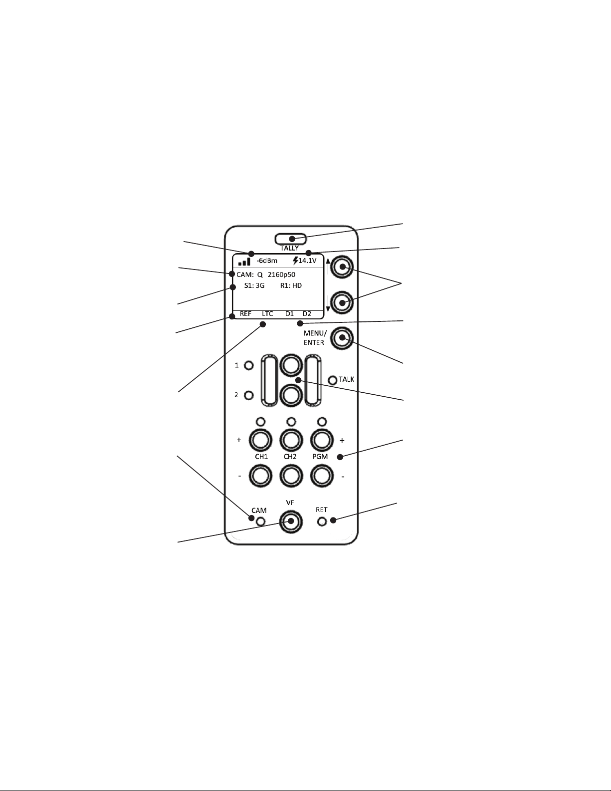
Control Panel Indicators and Controls
Fiber Signal Strength
Camera Video Status
3G Video Status
Reference Status
Timecode Status
Camera LED
Viewfinder Controls
Intercom Push-to-Talk Buttons
Tal ly In di cat or
System Voltage and Source Indicator
Menu Navigation Controls
Serial Data Status
Menu Selection Control/
ENTER Button
Headset Volume Controls
Return LED

SilverBack V Camera-Mountable Fiber Optic Transmission System
© 2021 MultiDyne, Inc. Made in the USA Page
24
Control Panel Navigation
MENU/ENTER
• Press to open display main menu.
• Press again to select feature
UP/DOWN Arrow Buttons
• Use to navigate control panel Status pages and sub menus.
TALLY Indicator
• Illuminates when camera is live.
TALK 1 & 2
• TALK buttons provide momentary or latching PTT functionality for channels 1 and 2, either
separately or simultaneously.
CH1, CH2 and PGM + or –
• Adjust intercom or program audio volume in the headset.
• LEDs indicate presence of intercom or program audio on each channel.
VF
• Determines which video signal is being sent to the viewfinder. This could be either the camera
output or the return sent by the base unit.
CAM
• Illuminates when receiving camera output.
RET
• Illuminates when receiving base unit signal.
SilverBack V Camera-Mountable Fiber Optic Transmission System
© 2021 MultiDyne, Inc. Made in the USA Page
25
CONTROL PANEL: STATUS SCREENS
General Instructions
The display on the camera unit shows signal and system status on a series of Status pages. The various
Status pages are accessed from the Home screen by pressing the UP/DOWN arrow buttons.
Status Screens
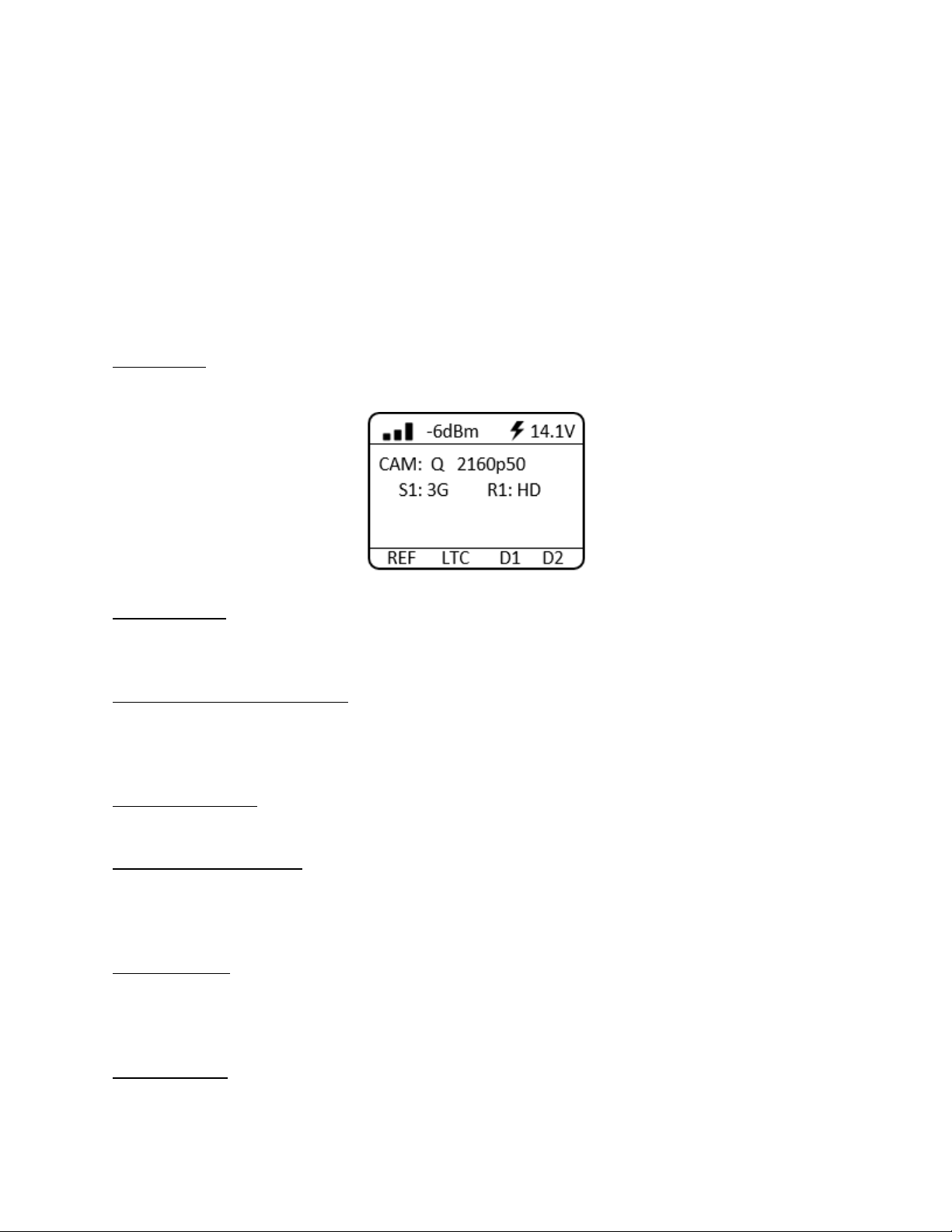
Home Screen
The Home status screen shows the most commonly needed system status information.
Fiber Link Status: Fiber Link status is shown both graphically as a series of bars and as an absolute signal
strength reading. Fiber Link status is also color-coded green/yellow/red for easy assessment of the fiber
signal strength.
System Voltage and Source Status: System output voltage to the camera is displayed, as well as whether
the camera unit is operating on hybrid fiber power (lightning bolt) or from an external battery (battery
symbol). Voltage and Source status are color-coded green/yellow/red for easy assessment of battery
and camera voltage.
Camera Video Status: The video format being generated by the camera is shown on the line labeled
CAM. For systems with an included 4K gearbox, the video resolution and frame rate will be displayed.
Secondary SDI Video Status: The video rate of the secondary SDI paths is shown here. Some systems
may have more than one status line, depending on the number of included secondary SDI paths. Video
sends from the camera unit (inputs) are shown with an “S” prefix. Video returns to the camera unit
(outputs) are shown with an “R” prefix.
Reference Status: Reference Status (REF) will turn red when there is no reference sync signal connected
at the base unit. REF will turn green when it has locked to the reference signal connected at the base
unit. While the camera unit is locking to a reference signal, REF will turn yellow and display a countdown
timer.
Timecode Status: Timecode status (LTC) will turn red when there is no timecode signal connected at the
base unit. LTC will turn green when it has detected a timecode signal connected at the base unit.
SilverBack V Camera-Mountable Fiber Optic Transmission System
© 2021 MultiDyne, Inc. Made in the USA Page
26
Data Status D1, D2: D1 and D2 display data activity on the Data 1 and Data 2 serial ports. The indicator
will turn green when data activity is detected.
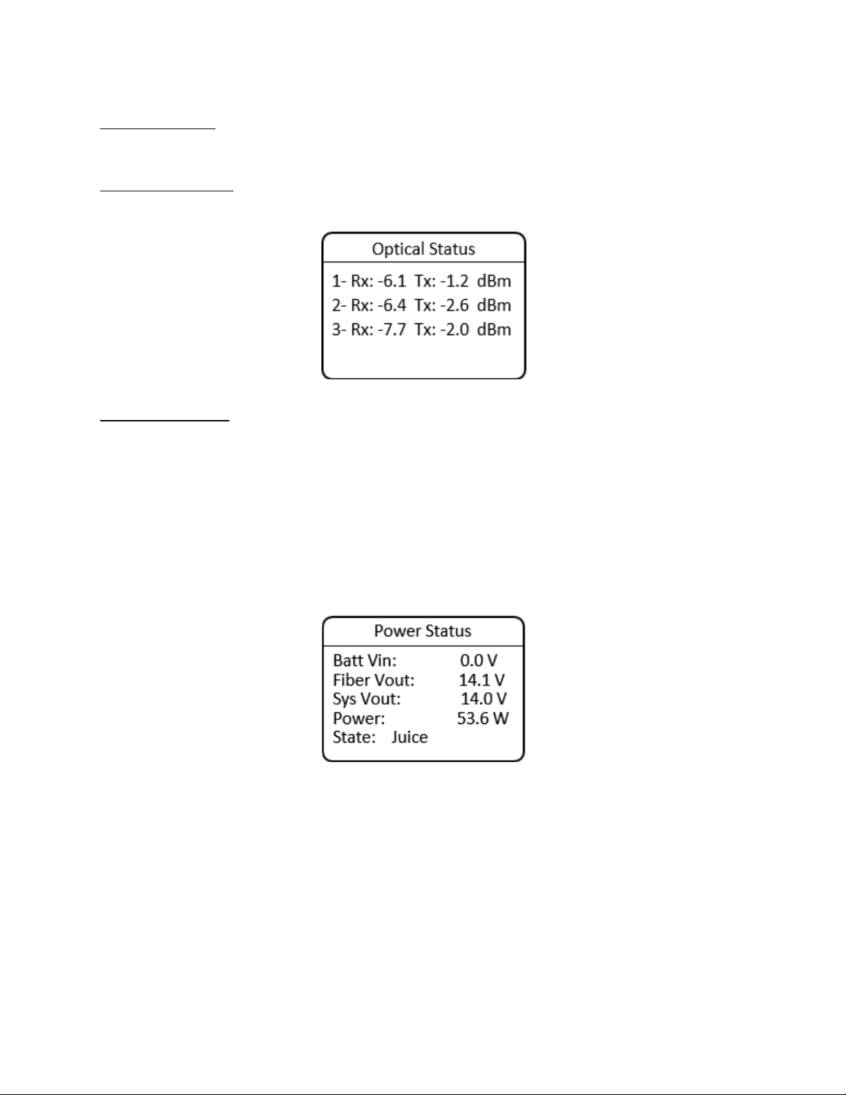
Optical Status Screen
The Optical Status screen shows the optical receive and transmit power of the internal optics.
Power Status Screen
The Power Status screen shows detailed system power information:
• Batt Vin: Displays the voltage of a connected battery.
• Fiber Vout: Displays the voltage being supplied by the hybrid fiber internal power converter.
• Sys Vout: Displays the system output voltage to the camera.
• Power: Displays the system power consumption in watts.
• State: Displays whether the system is operating from hybrid fiber power (Juice), battery, or Juice
with battery backup.
SilverBack V Camera-Mountable Fiber Optic Transmission System
© 2021 MultiDyne, Inc. Made in the USA Page
27
CONTROL PANEL: CAMERA UNIT MENUS
General Instructions
All menus in the SilverBack V camera unit control panel function similarly. MENU/ENTER displays the
Main menu.
Navigation within the menus:
• UP/DOWN arrows highlight menu options.
• MENU/ENTER toggles between or selects option.
• Select BACK and then ENTER to return to the previous menu.
• Select HOME and then ENTER to return to the main status screen.
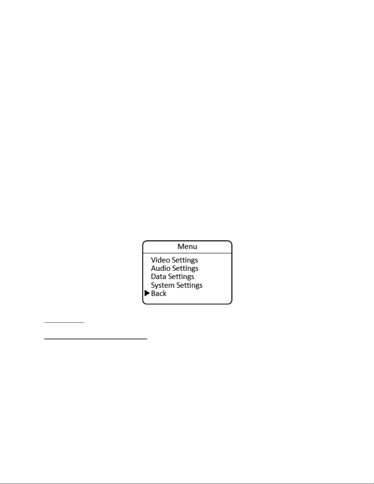
Main Menu
The Main menu shows the setting options:
• Video Settings: Gearbox and viewfinder setup
• Audio Settings: Input, output, and intercom settings
• Data Settings: Data transmission settings
• System Settings: Timecode, fan, and maintenance settings
Video Settings
Gearbox Configuration and Operation
The gearbox in the SilverBack V camera unit takes the main camera video output and multiplexes it into
a single video stream that is sent to the base unit. The gearbox accepts single-link, dual-link, and quad-
link video inputs at SMPTE data rates ranging from 1.5G (HD) up to 12G.
The gearbox Input mode must be configured to match the type of output the camera is providing, which
will be either a single-link, dual-link, or quad-link signal. The default setting from the factory is quad 3G.
SilverBack V Camera-Mountable Fiber Optic Transmission System
© 2021 MultiDyne, Inc. Made in the USA Page
28
Input Mode
Description
Single
The camera is outputting a single HD, 3G, 6G, or 12G stream.
Dual 3G
The camera is outputting a dual-link 3G stream (6G total).
Dual 6G
The camera is outputting a dual-link 6G stream (12G total).
Quad HD
The camera is outputting a quad-link HD stream (6G total).
Quad 3G (default)
The camera is outputting a quad-link 3G stream (12G total).
The gearbox relies on SMPTE S352M Program Identification (PID) metadata embedded in the camera’s
output video stream to process the signal correctly. In some cases, this PID metadata may be missing or
incorrect, which can cause incompatibility with the gearbox.
The PID mode setting is used to configure how the gearbox uses the PID metadata to multiplex the video
into a single video stream. In most cases, the default setting of Auto should be used.
PID Mode
Description
Enable
Forces the gearbox to try to multiplex and convert a dual-link or quad-link signal
into a visible SMPTE-compliant single-link 2SI (2 Sample Interleave) Level-A video
stream with appropriate converted PID information.
Disable
Multiplexes a dual-link or quad-link signal into a single stream but maintains
original PID information.
Auto (default)
Automatically determines PID conversion mode based on incoming PID
information, number of links, and data rate.
The gearbox has certain limitations as to which dual-link and quad-link format inputs can be converted
into a SMPTE-compliant 6G or 12G single-link 2SI Level-A video stream. The gearbox cannot convert
Square Division (SD) format inputs into a 2SI format, nor can it convert Level-B format inputs to Level A.
The gearbox can accept and transport SD and Level-A format inputs; however, they must be de-
multiplexed in the gearbox in the base unit to their original format.
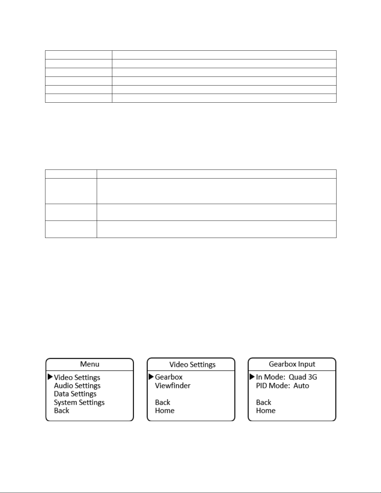
The gearbox is configured from the Video Settings menu.
MENU > Video Settings > Gearbox >
• In Mode: Select Single, Quad 3G, Quad HD, Dual 6G, or Dual 3G
• PID Mode: Select Auto, Enable, or Disable
The Camera Gearbox may also be configured remotely, from the webpage dashboard accessed from the
Base Unit.
SilverBack V Camera-Mountable Fiber Optic Transmission System
© 2021 MultiDyne, Inc. Made in the USA Page
29
Viewfinder Configuration and Operation
On certain SilverBack V camera unit models, some of the secondary SDI connections can be re-assigned
in the Settings menu to connect to a built-in internal viewfinder switch. The camera unit configurations
that support a built-in viewfinder switch are shown in the table below.
Configuration
C3EO
C3GX
C2X2
C4K1
C4K2
C42R
C44R
C3X3
Viewfinder Switch
YES
YES
YES
YES
YES
YES
YES
YES
Three types of 3G-SDI cards can be installed in internal card slots: 2Tx, 2Rx, and TRx. Typically, a VF-
capable card is installed in the slot closest to the Ethernet or audio connectors.
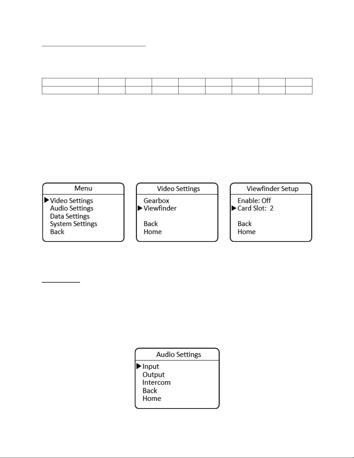
The viewfinder is configured from the Viewfinder Setup menu under Video Settings.
MENU > Video Settings > Viewfinder >
• Enable: On or Off (default)
• Card Slot: 1-4 (available slots depend on the number and type of SDI cards installed)
The Camera Viewfinder may also be configured remotely, from the webpage dashboard accessed from
the Base Unit.
Audio Settings
SilverBack V camera unit audio input and output are configured in the Audio Settings menu.
MENU > Audio Settings
• Input
• Output
• Intercom
SilverBack V Camera-Mountable Fiber Optic Transmission System
© 2021 MultiDyne, Inc. Made in the USA Page
30
Audio Input Settings
The SilverBack V camera unit can accept analog line or MIC level inputs on the two miniXLR input
connectors and/or analog Line or AES input on the high-density MDR connector. Audio input channels 1
and 2 can be taken either from the miniXLR connectors for MIC/Line applications or from the MDR
connector for Line/AES applications. Audio input channels 3 and 4 are always from the MDR connector.
Audio Inputs 1 and 2, MIC or Line Mode, miniXLR Connectors
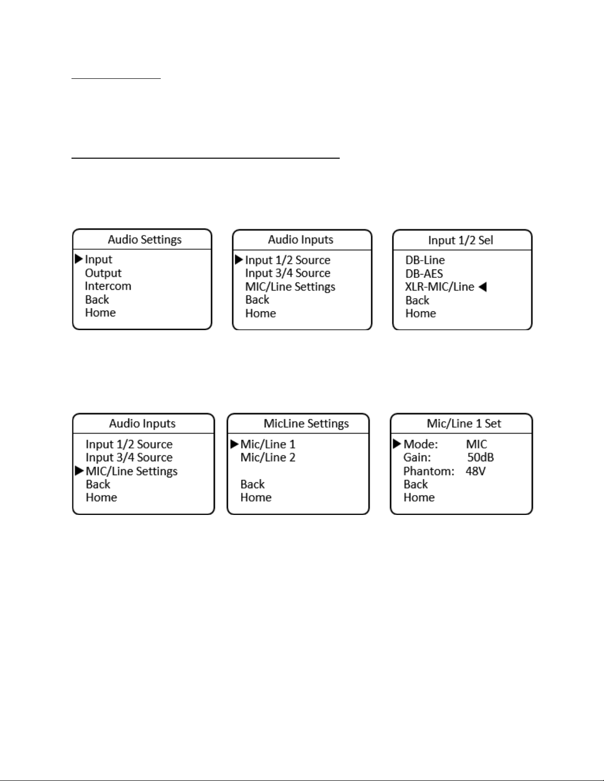
To configure the camera unit’s inputs for audio channels 1 and 2 for MIC/Line mode, navigate to the
Audio Inputs menu, select Input 1/2 Source, then XLR-MIC/Line.
MENU > Audio Settings >Audio Inputs > Input 1/2 Source > XLR-MIC/Line
After setting the source, navigate back one level and select the MIC/Line Settings menu to configure
each input.
MENU > Audio Settings > Audio Inputs > MIC/Line Settings
From here, the settings for each individual input are made. The settings for these two inputs are
independent of each other; one may be set for MIC mode while the other is in Line mode, for example.
Navigate to the MIC/Line 1 Settings menu.
MENU > Audio Settings > Audio Inputs > MIC/Line Settings > MIC/Line 1 Settings
For Line mode, navigate to Mode and press Enter to toggle between MIC and Line modes until Line is
displayed. After selecting Line for Input 1, navigate back up a menu level to configure input 2, if desired.
When Line mode is selected, Phantom power is always turned off and Gain is fixed at 0 dB (unity).
For MIC mode, navigate to Mode and press Enter to toggle between MIC and Line modes until MIC is
displayed. After selecting MIC for input 1, the previously used Gain and Phantom settings are recalled.
SilverBack V Camera-Mountable Fiber Optic Transmission System
© 2021 MultiDyne, Inc. Made in the USA Page
31
Navigate to Gain and press Enter to toggle through the available Gain settings. Gain is adjustable in 5dB
increments. Navigate to Phantom and press Enter to turn Phantom power on or off, as desired. After
completing the MIC settings for Input 1, navigate back up a menu level to configure Input 2, if desired.
Use the same procedure to configure Input 2 for Line or MIC mode by navigating to the MIC/Line 2
Settings menu.
MENU > Audio Settings > Audio Inputs > MIC/Line Settings > MIC/Line 2 Settings
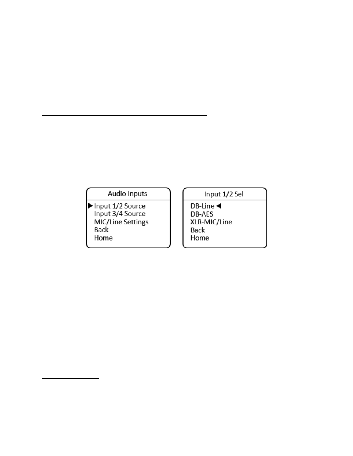
Audio Inputs 1 and 2, Line or AES Mode, High-Density Connector
To configure the camera unit’s inputs for audio channels 1 and 2 for Line or AES mode using the high-
density connector, navigate to the Audio Inputs menu, select Input 1/2 Source, then select either DB-
Line or DB-AES, as desired. These inputs are treated as a stereo pair together and cannot be split
between analog and AES.
MENU > Audio Settings > Audio Inputs > Input 1/2 Source > DB-Line
or
MENU > Audio Settings >Audio Inputs > Input 1/2 Source > DB-AES
When selecting AES for inputs 1 and 2, the input is taken from the channel 1 input. After setting the
source, navigate back one level to configure the settings for input 3 and 4.
Audio Inputs 3 and 4, Line or AES Mode, High-Density Connector:
To configure the camera unit’s inputs for audio channels 3 and 4 for Line or AES mode using the high-
density connector, navigate to the Audio Inputs menu, select Input 3/4 Source, then select either DB-
Line or DB-AES, as desired. These inputs are treated as a stereo pair and cannot be split between analog
and AES. They may be set differently than inputs 1 and 2, however.
MENU > Audio Settings >Audio Inputs > Input 3/4 Source > DB-Line
or
MENU > Audio Settings >Audio Inputs > Input 3/4 Source > DB-AES
When selecting DB-AES for inputs 3 and 4, the input is taken from the channel 3 input.
Audio Output Settings
The SilverBack V camera unit outputs four channels of analog Line-level or AES audio on the high-density
MDR connector.
SilverBack V Camera-Mountable Fiber Optic Transmission System
© 2021 MultiDyne, Inc. Made in the USA Page
32
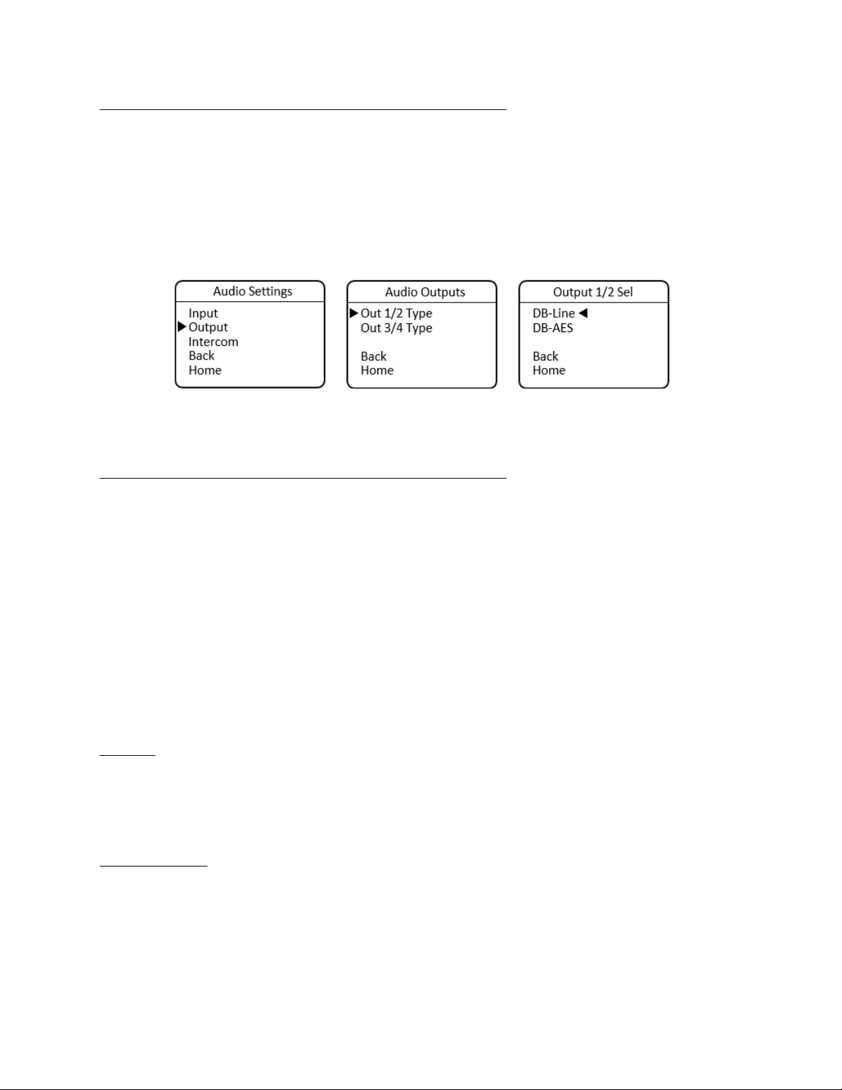
Audio Outputs 1 and 2, Line or AES Mode, High-Density Connector
To configure the camera unit’s outputs for audio channels 1 and 2 for Line or AES mode using the high-
density connector, navigate to the Audio Outputs menu, select Out 1/2 Type, then select either DB-Line
or DB-AES, as desired. These outputs are treated as a stereo pair and cannot be split between analog
and AES.
MENU > Audio Settings > Audio Outputs > Out 1/2 Type > DB-Line
or
MENU > Audio Settings > Audio Outputs > Out 1/2 Type > DB-AES
When selecting AES for outputs 1 and 2, the output is taken from channel 1. After setting outputs for
channels 1 and 2, navigate back one level to configure the output settings for channel 3 and 4.
Audio Outputs 3 and 4, Line or AES Mode, High-Density Connector
To configure the camera unit’s outputs for audio channels 3 and 4 for Line or AES mode using the high-
density connector, navigate to the Audio Outputs menu, select Out 3/4 Type, then select either DB-Line
or DB-AES, as desired. These outputs are treated as a stereo pair and cannot be split between analog
and AES.
MENU > Audio Settings > Output > Out 3/4 Type > DB-Line
or
MENU > Audio Settings > Output > Out 3/4 Type > DB-AES
When selecting AES for outputs 3 and 4, the output is taken from the channel 3 output.
The Camera Unit audio settings may also be configured remotely, from the webpage dashboard
accessed from the Base Unit.
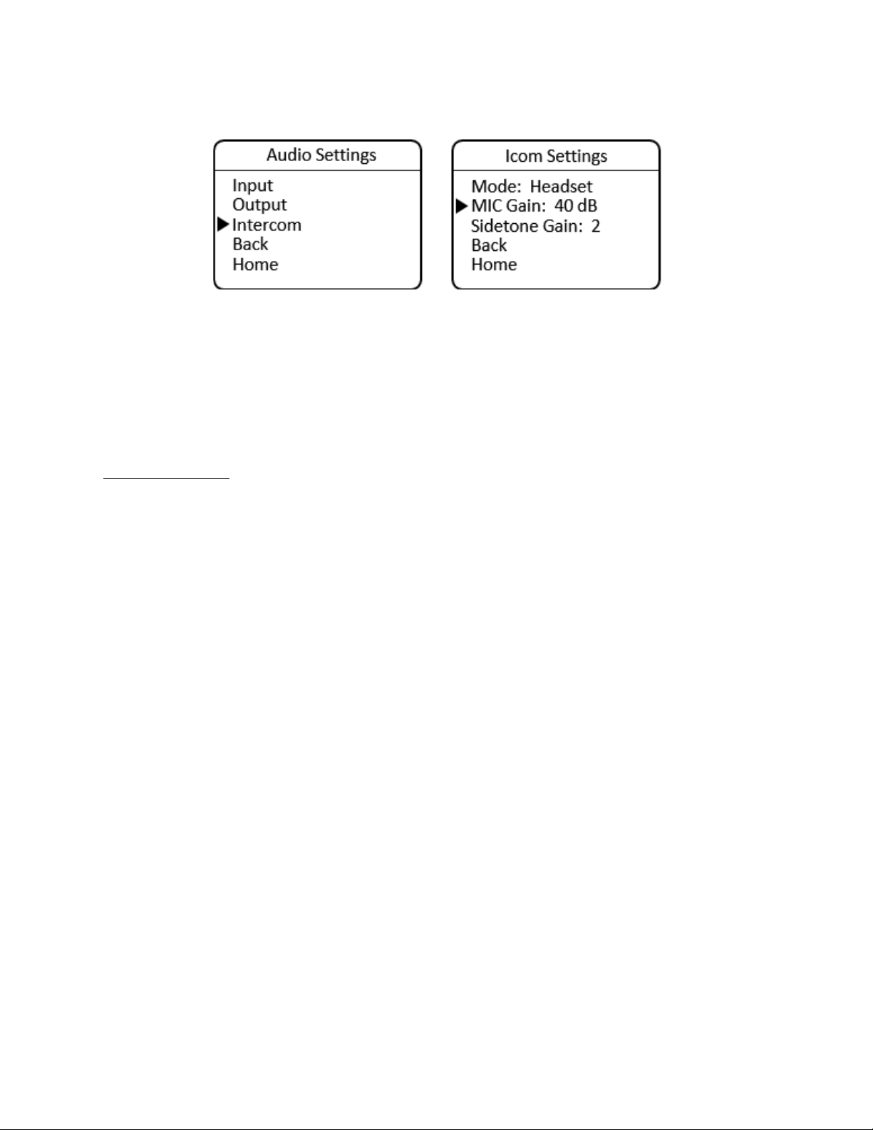
Intercom
The SilverBack V camera unit uses a 5-pin miniXLR connector to allow use of either single-muff or dual-
muff intercom headsets. Headset MIC Gain and Sidetone settings are adjusted from within the Intercom
Settings menu. Volume and talkback control are provided using dedicated buttons on the control panel
for quick access.
Intercom Settings
To configure headset MIC Gain, navigate to the Audio Settings menu, select Intercom, and then select
MIC Gain. Press Enter to toggle through the available Gain settings and stop at the desired setting.
SilverBack V Camera-Mountable Fiber Optic Transmission System
© 2021 MultiDyne, Inc. Made in the USA Page
33
MENU > Audio Settings > Intercom Settings > MIC Gain
To configure headset Sidetone Gain, navigate to the Audio Settings menu, select Intercom, then select
Sidetone Gain. Press Enter to toggle through the available Gain settings and stop at the desired setting.
MENU > Audio Settings > Intercom > Sidetone Gain
The Camera Intercom settings may also be configured remotely, from the webpage dashboard accessed
from the Base Unit.
Intercom Operation
Volume controls are provided on the camera unit control panel for adjusting the audio levels of
Intercom 1 (CH1), Intercom 2 (CH2), and Program (PGM) audio heard in the headset. The volume
controls allow both intercom channels and program audio to be heard in the headset simultaneously.
A LED above each channel’s set of volume control buttons will illuminate whenever audio is present on
that channel. When adjusting the volume, these LEDs will rapidly blink three times whenever the
minimum or maximum volume setting has been reached.
Two push-to-talk (PTT) switches are provided on the camera unit control panel, one for each intercom
channel. Each PTT switch provides Momentary or Latching operation of the headset microphone to
allow the operator to talk on a particular intercom channel, or on both channels simultaneously.
To talk on an intercom channel using Momentary mode:
1. For the desired channel, channel 1 or 2, press and hold the desired PTT switch, then speak into
the microphone.
2. The TALK LED and selected channel TALK LED will blink and the microphone will remain open
while the PTT switch is held.
3. When finished with the conversation, release the PTT button.
4. The microphone will shut off and the TALK LEDs will turn off.
To talk on an intercom channel using Latching mode for longer-term hands-free operation:
1. Quickly press and release the PTT switch for channel 1 or channel 2.
2. The microphone will latch open and TALK LED and the selected channel TALK LED will blink
continuously.
3. When finished with the conversation, quickly press and release the PTT switch again.
4. The microphone will shut off and the TALK LEDs will turn off.
SilverBack V Camera-Mountable Fiber Optic Transmission System
© 2021 MultiDyne, Inc. Made in the USA Page
34
To talk on both intercom channels simultaneously (latching Mode only):
1. Quickly press and release the PTT switch for channel 1.
2. The microphone will latch open and the TALK and Ch1 TALK LEDs will blink continuously.
3. Quickly press and release the PTT switch for channel 2.
4. The microphone will stay open and the Ch2 TALK LED will now also blink continuously.
5. When finished with the conversation, quickly press and release the PTT 1 switch again to shut
off channel 1 and then repeat for channel 2.
6. The microphone will shut off and the TALK LEDs will turn off.
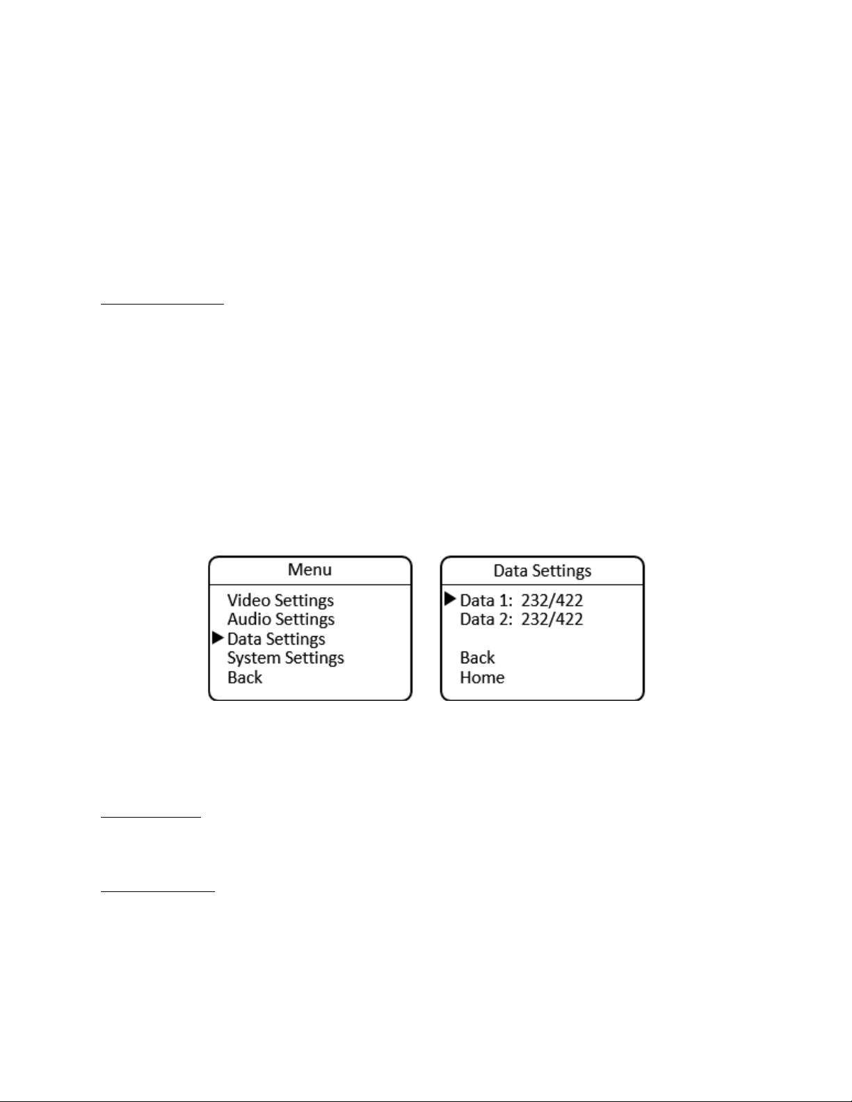
Serial Data Settings
The SilverBack V camera unit’s Serial Data Channel settings are configured in the Data Settings Menu.
Each data port can be configured for RS232/RS422 type data or LANC control data. The factory default
setting is RS232/422.
To configure a data channel, navigate to the Main menu and select Data Settings. Move to the Data 1
selection line and press Enter to toggle through the available settings. Then move to the Data 2 selection
line and press Enter to toggle through the available settings.
MENU > Data Settings >
• Data 1: 232/422 or LANC
• Data 2: 232/422 or LANC
The Camera serial data settings may also be configured remotely, from the webpage dashboard
accessed from the Base Unit.
System Settings
The System Settings menu provides system information and allows control of some overall system
functions.
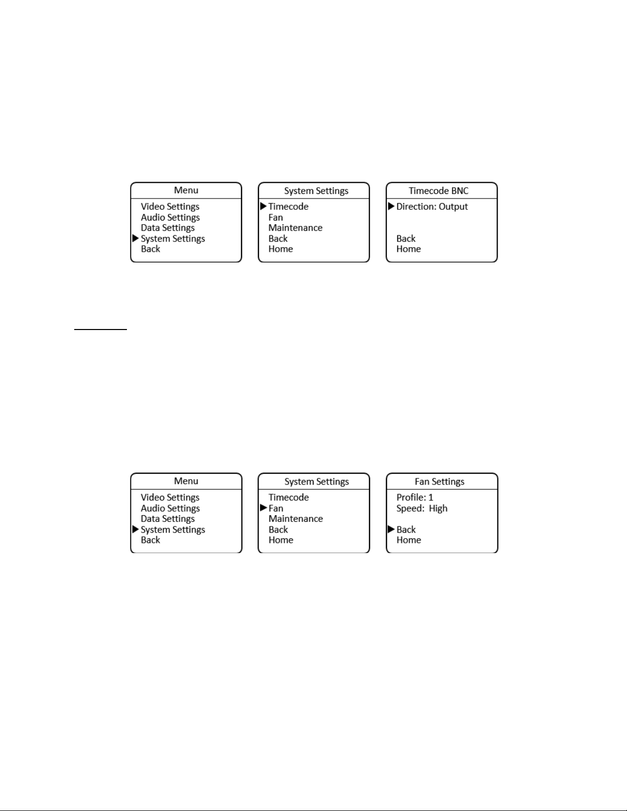
Timecode Settings
The SilverBack V camera unit has a single HDBNC connector for timecode transport. This connector can
be set as an input or an output, depending on the desired workflow. The factory default setting is
Output.
Timecode direction settings are found under the System menu. Navigate to the Main menu, select
SilverBack V Camera-Mountable Fiber Optic Transmission System
© 2021 MultiDyne, Inc. Made in the USA Page
35
System Settings, and from the System Settings menu select Timecode. On the Timecode BNC menu,
select Direction and press Enter to toggle through the available settings.
The Camera timecode settings may also be configured remotely, from the webpage dashboard accessed
from the Base Unit.
MENU > System Settings > Timecode BNC
Some cameras utilize only a single connector for timecode. In this case, please ensure the timecode port
direction on the camera is also set accordingly.
Fan Control
To change the speed of the internal fan, navigate to the Main menu, select System Settings, then Fan.
The Profile is a factory setting and should be kept at the default setting of 1. For fan speed, the choices
are Off, Low, Med, and High. It is recommended to keep the speed setting at high to ensure maximum
cooling.
MENU > System Settings > Fan Settings
• Profile: 1 to 4
• Speed: Low, Medium, High, or Off
The Camera fan settings may also be configured remotely, from the webpage dashboard accessed from
the Base Unit.
SilverBack V Camera-Mountable Fiber Optic Transmission System
© 2021 MultiDyne, Inc. Made in the USA Page
36
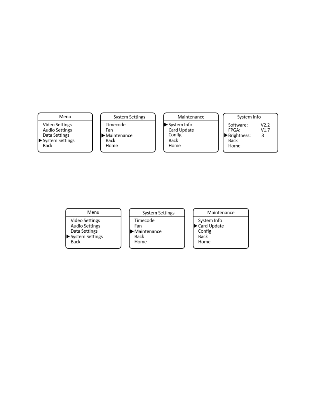
System Information
The System Info menu displays the software versions of the unit, as well as provides control of the
brightness of the OLED display and LEDs on the control panel.
MENU > System Settings > Maintenance > System Info
• Software: Version number
• FPGA: Version number
• Brightness: Select 1 to 5
Card Update
To update system software from a MicroSD card installed in the side of the control panel, navigate to
the Main menu, select System Settings, then Maintenance, then Card Update. Camera Unit software
can also be updated remotely from the Base Unit. See Appendix C for more details.
SilverBack V Camera-Mountable Fiber Optic Transmission System
© 2021 MultiDyne, Inc. Made in the USA Page
37
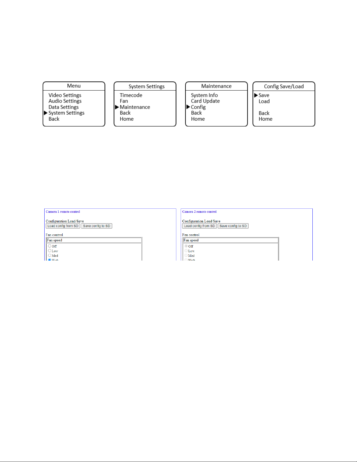
Saving and Recalling Settings
Camera Unit configuration settings can be saved to a microSD card for easy recall or to share between
camera units. The Configuration Load/Save Menu is accessed from the Maintenance Menu.
Note: In order to use the configuration save/recall feature, the microSD card must have a valid, existing
cconfig.txt file on it. This file may be obtained from MultiDyne service or can be created on the Base
Unit microSD card and then copied to another card for use in the camera unit (see below).
Camera Unit configuration settings may also be saved or recalled, remotely, from the webpage
dashboard that is accessed via the Base Station. Navigate to the Camera Configuration Load/Save
Settings Box on the webpage and then click the Load or Save button as desired. Configuration will be
saved to the microSD card in the Base Unit
SilverBack V Camera-Mountable Fiber Optic Transmission System
© 2021 MultiDyne, Inc. Made in the USA Page
38
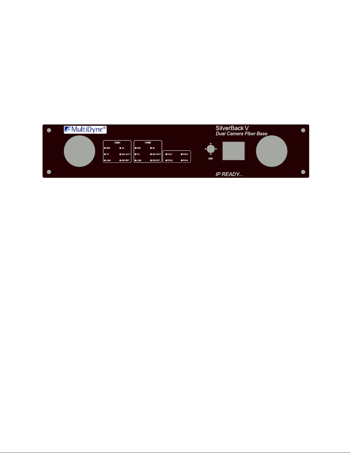
BASE UNIT OPERATION
The front panel on the SilverBack V base unit provides a simple interface that allows operators to
monitor system link and signal status using LEDs and a TFT display. A joystick provides navigation
assistance to reach menu options for further status and system configuration.
Front Panel Indicators and Controls
Control Panel Layout
SilverBack V Camera-Mountable Fiber Optic Transmission System
© 2021 MultiDyne, Inc. Made in the USA Page
39
BASE UNIT MENUS
General Instructions
All menus in the SilverBack V base unit control panel function similarly:
• NAV multidirectional actuator (joystick) allows you to move through the menus.
• Press in the center to select.
When in the menus:
• Select BACK to return to the previous menu.
• Select HOME to return to the main menu.
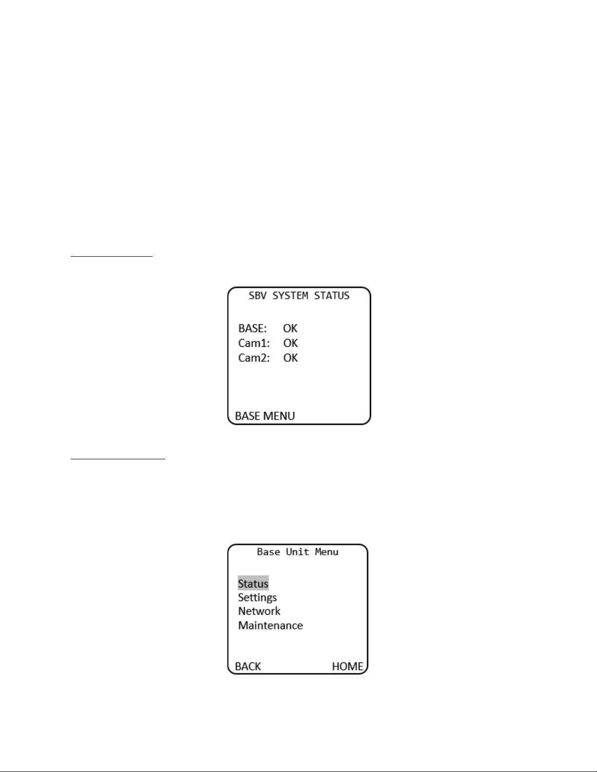
SBV System Status
The Home screen on the base unit displays a quick overview of SilverBack V system status.
Base Unit Root Menu
• Status: Fiber/Video/Audio/Intercom/Power
• Settings: Audio Input/Audio Output/Video/Intercom/Reference/Data
• Network
• Maintenance
SilverBack V Camera-Mountable Fiber Optic Transmission System
© 2021 MultiDyne, Inc. Made in the USA Page
40
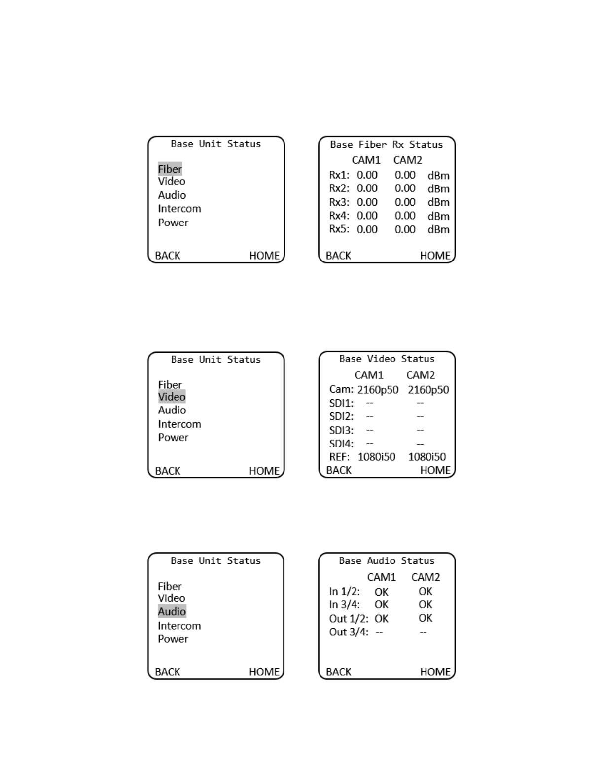
The Base Fiber Rx Status menu displays GBX, 3G or COR for video channels 1 and 2 depending on the
cards installed.
Base Unit Menu > Status > Fiber > Base Fiber Rx Status
The Base Video Status menu displays video resolution for video channels 1 and 2 depending on the cards
installed.
Base Unit Menu > Status > Video > Base Video Status
Base Unit Menu > Status > Audio > Base Audio Status
The Base Audio Status menu displays “OK” if there is audio on each respective audio channel.
SilverBack V Camera-Mountable Fiber Optic Transmission System
© 2021 MultiDyne, Inc. Made in the USA Page
41
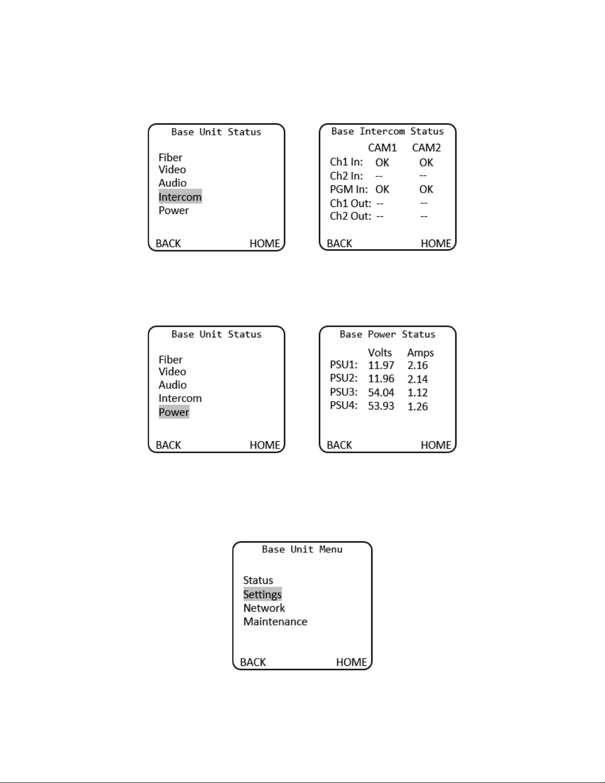
Base Unit Menu > Status > Intercom > Base Intercom Status
The Base Intercom Status menu displays “OK” if there is audio on each respective audio channel.
Base Unit Menu > Status > Power > Base Power Status
The Base Power Status menu displays Volts and Amps settings for each power supply unit.
Base unit settings for Audio Input/Audio Output/Video/Intercom/Reference/Data are accessed via the
Base Unit Settings menu.
Base Unit Menu > Settings

SilverBack V Camera-Mountable Fiber Optic Transmission System
© 2021 MultiDyne, Inc. Made in the USA Page
42
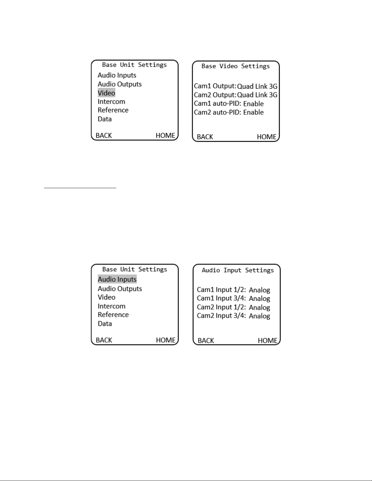
Gearbox Configuration and Operation
The gearbox in each camera chain in the SilverBack V base unit receives the main camera video stream
from the camera unit and de-multiplexes it back into its original video format.
The gearbox mode must be configured to match the type of output the camera is providing, which will
be either a single-link, dual-link, or quad-link signal. The default setting from the factory is Quad 3G.
Output Mode
Description
Single Link
The base unit outputs a single HD, 3G, 6G or 12G stream.
Dual Link 3G
The base unit outputs a dual-link 3G stream (6G total).
Dual Link 6G
The base unit outputs a dual-link 6G stream (12G total).
Quad Link HD
The base unit outputs a quad-link HD stream (6G total).
Quad Link 3G (default)
The base unit outputs a quad-link 3G stream (12G total).
The gearbox relies on SMPTE S352M PID metadata embedded in the camera’s output video stream to
process the signal correctly. In some cases, PID metadata from the camera may be missing or incorrect,
which can cause incompatibility with the gearbox.
The PID Mode setting is used to configure how the gearbox processes the PID metadata from the
camera. In most cases, the default setting of Auto should be used.
Auto PID Mode
Description
Enable (default)
Automatically determine video format conversion and PID conversion
modes based on incoming PID information and Output mode setting.
Disable
The gearbox will output video using the selected Output mode but will
maintain original PID information from the camera.
The gearbox has certain limitations as to which camera video formats can be converted between single-
link, dual-link, and quad-link video streams. The gearbox cannot convert Square Division (SD) camera
formats into a 2SI formats, nor can it convert Level-B formats to Level A. Only 2SI Level-A camera video
streams are capable of being converted between single-link, dual-link, and quad-link. The gearbox can
accept and transport SD and Level-A camera formats; however, they must always be de-multiplexed in
the gearbox in the base unit back to their original format.
The gearbox for each camera chain is configured from the Video Settings menu:
SilverBack V Camera-Mountable Fiber Optic Transmission System
© 2021 MultiDyne, Inc. Made in the USA Page
43
Base Unit Menu > Settings > Video > Base Video Settings
The Gearbox settings may also be configured from the webpage dashboard accessed from the Base Unit.
Audio Input Configuration
The SilverBack V base unit can accept analog Line-level or AES inputs on the DB25 connector.
To configure the base unit audio inputs for Line or AES mode, navigate to the Base Unit Settings menu
and select Audio Inputs, then either Analog or AES as desired for each camera chain. Audio inputs are
treated as stereo pairs for channels 1 and 2 and channels 3 and 4. When selecting AES for either input
pair, the physical input is taken from the odd numbered input channel on the connector.
Base Unit Menu > Base Unit Settings > Audio Input Settings
The Audio input settings may also be configured from the webpage dashboard accessed from the Base
Unit.
SilverBack V Camera-Mountable Fiber Optic Transmission System
© 2021 MultiDyne, Inc. Made in the USA Page
44
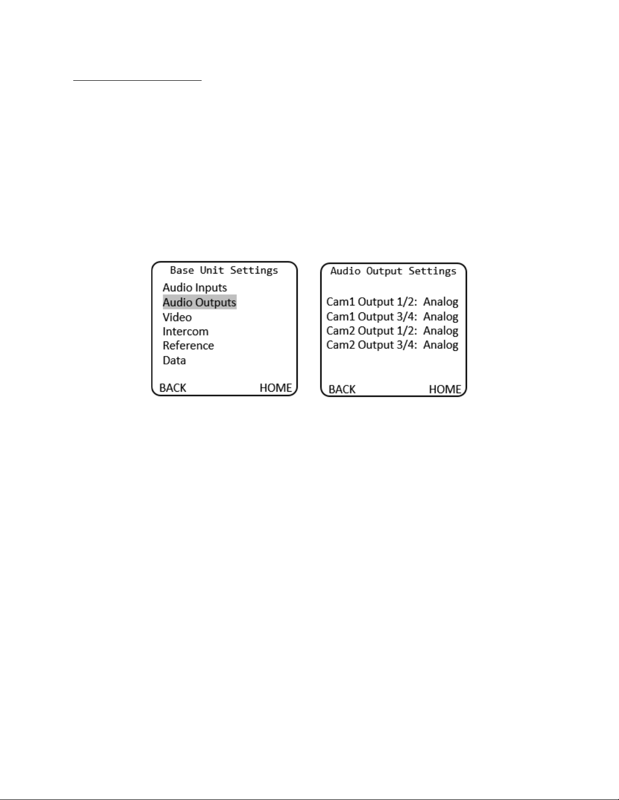
Audio Output Configuration
The SilverBack V base unit can output analog Line-level or AES audio on the audio DB25 connector.
To configure the base unit audio outputs for Line or AES mode, navigate to the Audio Output Settings
Menu and select either Analog or AES as desired for each camera chain. Audio outputs are treated as
stereo pairs for channels 1 and 2 and channels 3 and 4.
To configure the base unit audio outputs for Line or AES mode, navigate to the Base Unit Settings menu
and select Audio Outputs, then either Analog or AES for each camera chain. Audio outputs are treated as
stereo pairs for channels 1 and 2 and channels 3 and 4. When selecting AES for either output pair, the
physical output is taken from the odd numbered output channel on the connector.
Base Unit Menu > Settings > Audio Outputs >
The Audio output settings may also be configured from the webpage dashboard accessed from the Base
Unit.
SilverBack V Camera-Mountable Fiber Optic Transmission System
© 2021 MultiDyne, Inc. Made in the USA Page
45
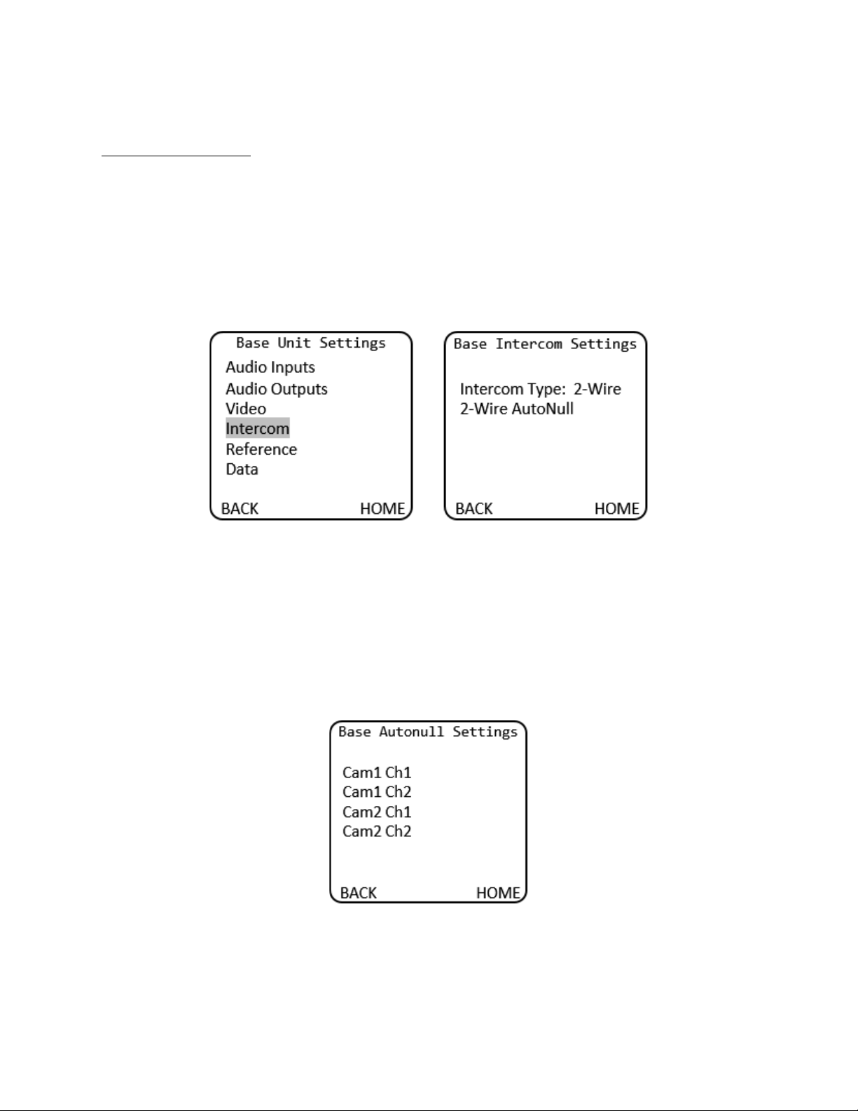
Intercom Configuration
The SilverBack V base unit can interface with either 4-wire or 2-wire party-line intercom systems using
the intercom/GPIO DB25 connector.
To configure the base unit intercom interface for 4-wire or 2-wire mode, navigate to the Base Unit
Settings menu and select Intercom, then either 4-wire or 2-wire. Both camera chains in the base unit
share the same interface type automatically.
Base Unit Menu > Base Unit Settings > Base Intercom Settings
For 2-wire intercom systems, it is recommended that an AutoNull be performed whenever any device is
physically added or removed from the 2-wire party line. To AutoNull any of the 2-wire intercom
channels, select the 2-wire AutoNull menu and click on the desired channel to be nulled. The AutoNull
process takes about 30 seconds to complete for each channel while a series of tones are transmitted on
that party line.
Base Unit Menu > Base Unit Settings > Base Intercom Settings > 2-Wire AutoNull
The Intercom settings may also be configured from the webpage dashboard accessed from the Base
Unit.
SilverBack V Camera-Mountable Fiber Optic Transmission System
© 2021 MultiDyne, Inc. Made in the USA Page
46
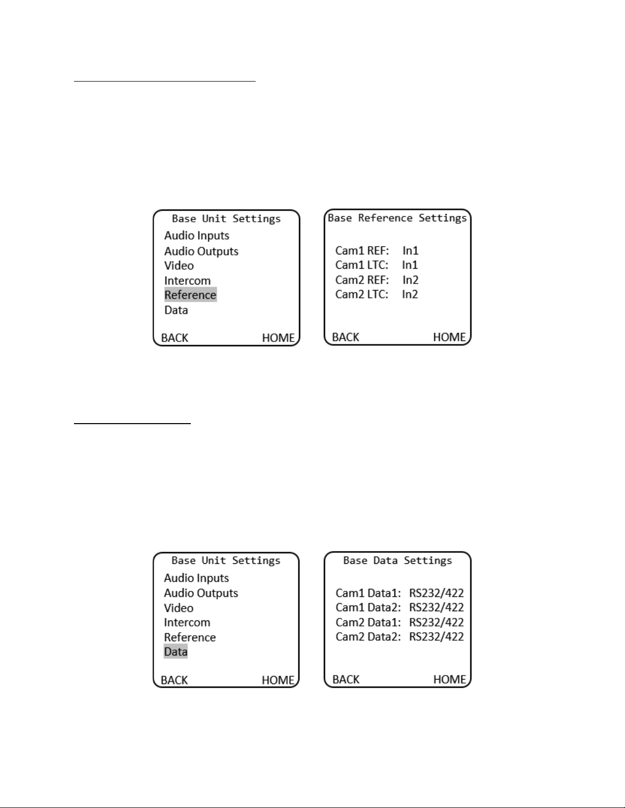
Reference and Timecode Configuration
Each camera chain in the SilverBack V base unit has dedicated reference sync and timecode inputs. For
dual camera chain systems, either chain’s reference or timecode input may be internally routed to
either or both of the camera chains.
To configure the base unit reference and timecode settings, navigate to the Base Unit Settings menu
and select Reference, then select the desired REF and LTC input for each camera chain.
Base Unit Menu > Base Unit Settings > Base Reference Settings
The reference and timecode routing settings may also be configured from the webpage dashboard
accessed from the Base Unit.
Serial Data Configuration
SilverBack V base unit Serial Data Channel settings are configured in the Data Settings menu. Each data
port can be configured for RS232/RS422 type data or LANC control data. The factory default settings are
RS232/422.
To configure a data channel, navigate to the Base Unit Settings menu and select Data, then select the
desired data types for the camera and data ports of each camera chain.
Base Unit Menu > Base Unit Settings > Base Data Settings
The serial data settings may also be configured from the webpage dashboard accessed from the Base
Unit.
SilverBack V Camera-Mountable Fiber Optic Transmission System
© 2021 MultiDyne, Inc. Made in the USA Page
47
Base Unit Network Configuration
The SilverBack V base unit can monitor the Status and Control settings of the system through a web-
based dashboard embedded within the frame controller software. The procedure for connecting to a
facility Ethernet network will depend on the network requirements of the site. Your IT department
should be contacted before connecting to the facility network to avoid potential conflicts.
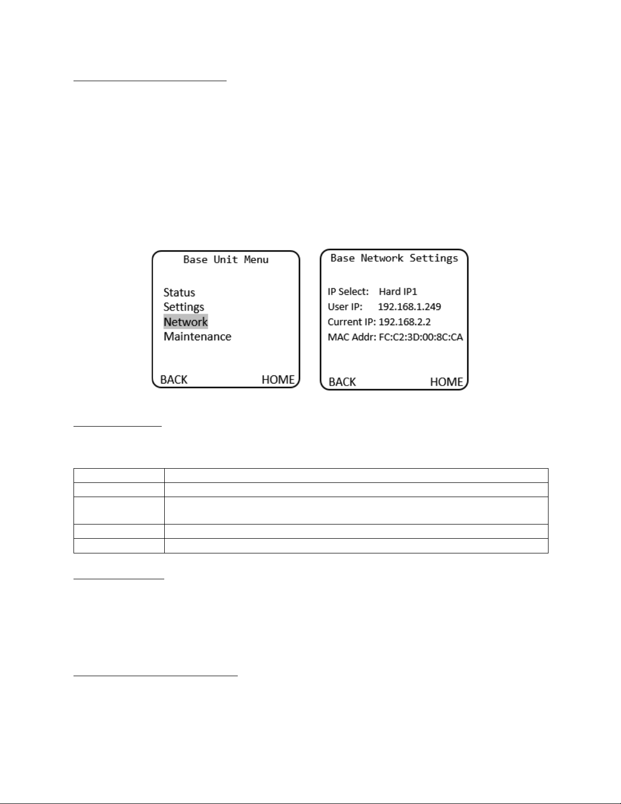
To display the current network settings of the frame controller card, navigate to the Base Unit menu on
the front panel display and select Network. No settings can be changed from the Base Network Settings
menu, as they are configured either from the DIP switch accessible from the rear of the unit or from the
dashboard web page.
Base Unit Menu > Base Network Settings
IP Address Settings
Four DIP switches on the rear of the SilverBack V chassis are used to set the network address. (Note:
Only one switch can be set to the ON position.)
DIP Switch #
Description
1
DHCP. Network settings assigned by a DHCP server.
2
User IP Address. IP address is set by the user through embedded web page.
Factory default is 192.168.1.249.
3
Fixed IP Address #1. 192.168.2.2.
4
Fixed IP Address #2. 10.1.1.2
DHCP (DIP Switch 1)
Configures the SilverBack V base unit with an automatically assigned IP address. To configure the
network settings via DHCP:
• Using an Ethernet cable, connect the SilverBack V base unit to your network.
• Power up the SilverBack V base unit.
• Set the DIP switch #1 to ON to specify DHCP configured settings.
Preset IP Address (DIP Switch 3 or 4)
Set the DIP switch to specify the desired preset IP address (as outlined in the IP address DIP switch
table). Ensure that your computer and the SilverBack V base unit are on the same subnet. Contact your
IT department if you need help determining or configuring the network settings of your computer.
SilverBack V Camera-Mountable Fiber Optic Transmission System
© 2021 MultiDyne, Inc. Made in the USA Page
48
To prevent possible IP address conflicts:
• Initially isolate the SilverBack V base unit and your computer from the rest of your network by
unplugging all devices except the SilverBack V base unit and your computer.
or
• Use an Ethernet cable to connect the SilverBack V base unit directly to your computer.
From your computer, launch a web browser.
• Power up the SilverBack V base unit.
• In the address bar of the web browser, enter the preset IP address indicated on the DIP switch.
• Wait approximately 30 seconds while network communications are established.
• Verify that the SilverBack V base unit dashboard web page displays in the web browser.
• Should the web page fail to display after a minute or two:
o Click the refresh/reload button in your browser.
o Verify that the Ethernet cables are properly connected.
o Ensure that the LEDs on the Ethernet connector registers activity.
o Verify that you have properly performed each step of this procedure.
• If you and your IT team cannot establish a connection, contact MultiDyne Technical Support.
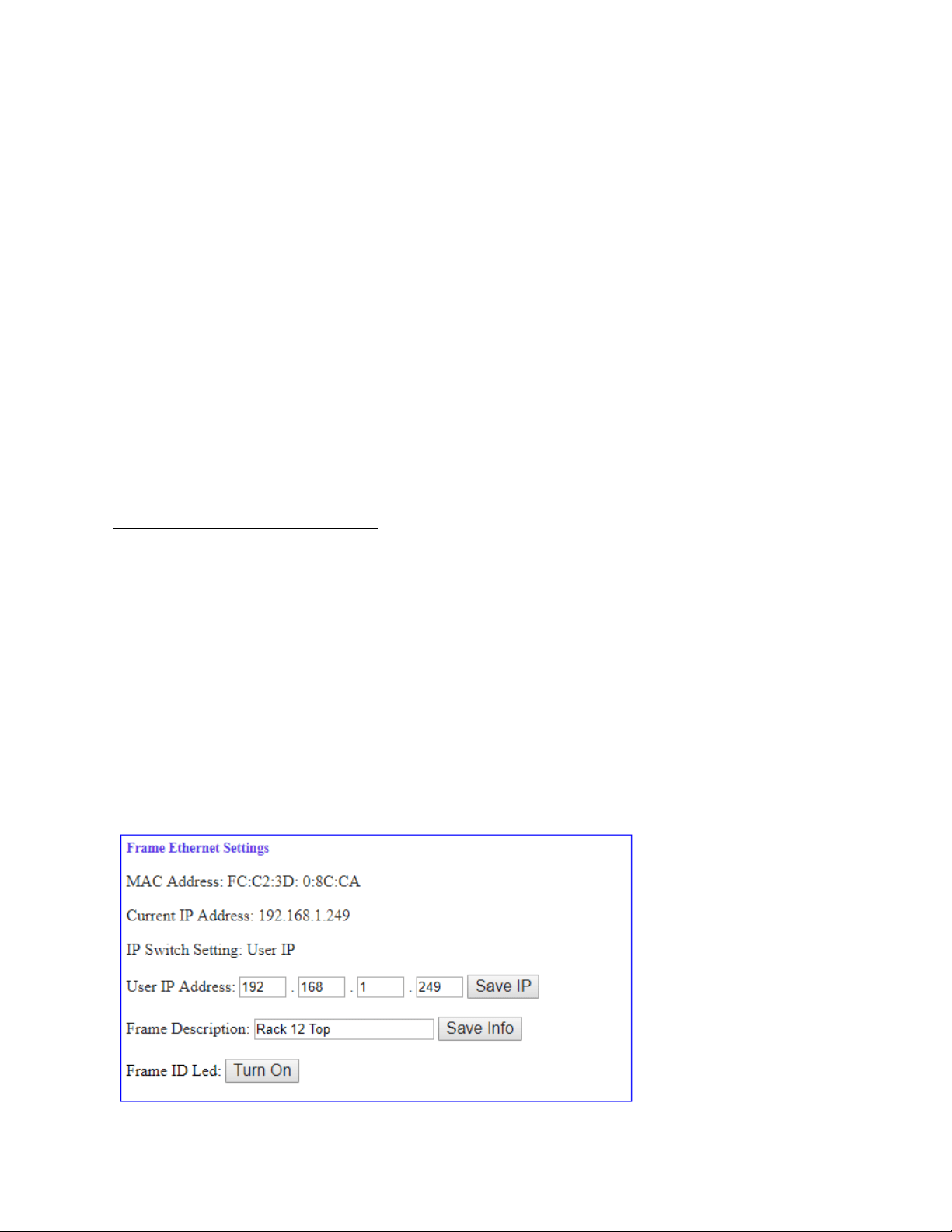
Custom User IP Address (DIP Switch 2)
With network communications established, you may wish to configure a custom static IP address
through the Frame Ethernet Settings box on the web page dashboard.
• Establish communications with the SilverBack V base unit by using one of the preset IP
addresses, DHCP, or previously configured User IP address.
• From your computer, launch a web browser and enter the previously established IP address.
• When the dashboard launches, enter the desired user IP address in the Frame Ethernet Settings
box. (Ensure that your computer and the SilverBack V base unit are on the same subnet. Contact
your IT Department if you need help determining or configuring the network settings of your
computer.)
• Verify the IP address. Click "Save IP". (The IP address is stored in non-volatile memory.)
• Switch the DIP switch #2 to ON. (If this switch is already on, you may need to toggle for the
address to take effect.)
• Verify the new IP address by entering it into a web browser address bar.
SilverBack V Camera-Mountable Fiber Optic Transmission System
© 2021 MultiDyne, Inc. Made in the USA Page
49
PRO TIP: Physically Identifying a SilverBack V Base Unit in a Facility
A LED on the rear of the frame controller card in the chassis can assist in identifying a SilverBack V base
unit amidst other rack-mounted gear. Turn this LED on or off from the Frame Ethernet Settings box on
the web page. The LED blinks when turned on.
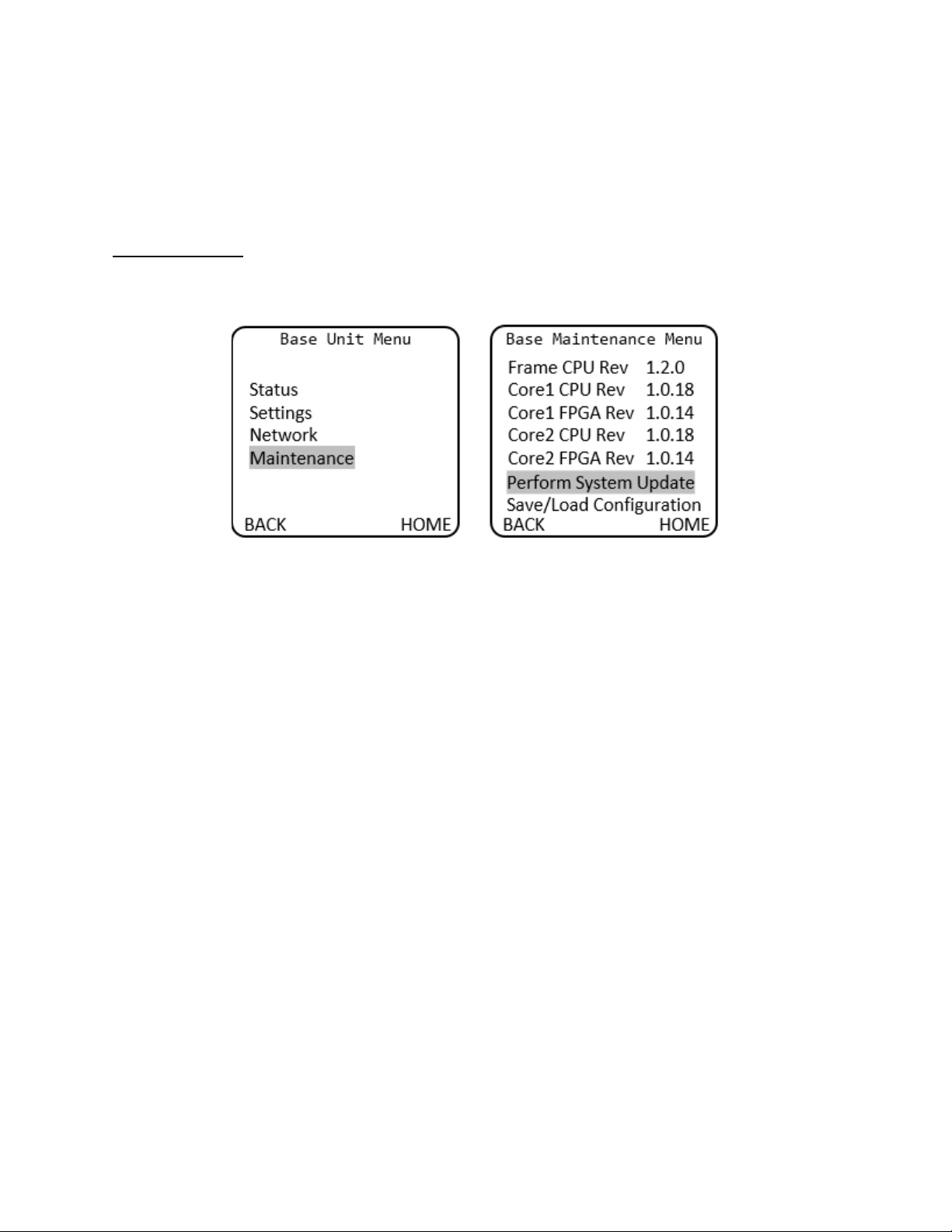
Firmware Updates
Base Unit Menu > Base Maintenance Menu
See the procedure for updating SilverBack V firmware in Appendix C of this manual. Software may also
be updated using the system webpage dashboard.
Base Unit Menu > Base Maintenance Menu > Perform System Update
• FW Name: Firmware to be flashed
• FW Size: Size in Bytes
• Update: Cam1 or Update Cam2
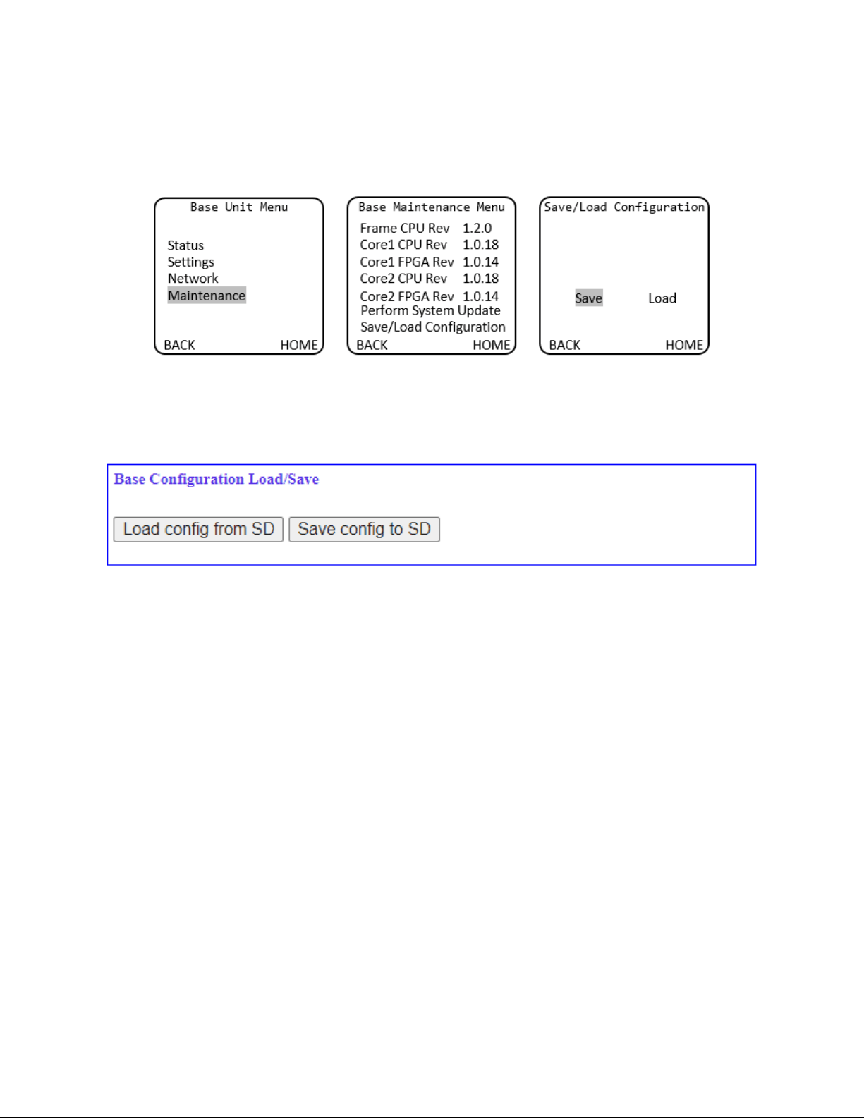
SilverBack V Camera-Mountable Fiber Optic Transmission System
© 2021 MultiDyne, Inc. Made in the USA Page
50
Saving and Recalling Settings
Base Unit configuration settings can be saved to the microSD card for easy recall or to share between
base units. The Configuration Load/Save Menu is accessed from the Maintenance Menu.
Configuration settings may also be saved or recalled from the webpage dashboard. Navigate to the Base
Configuration Load/Save Settings Box on the webpage and then click the Load or Save button as desired.

SilverBack V Camera-Mountable Fiber Optic Transmission System
© 2021 MultiDyne, Inc. Made in the USA Page
51
APPENDIX A - TECHNICAL SPECIFICATIONS
SDI Video
Interface
SMPTE ST259, ST292, ST425, ST2081, ST2082
Data Rate
270Mbps, 1.5Gbps, 3Gbps, 6Gbps, 12Gbps
Number of Channels (camera unit to base unit)
1 to 8, depending on model ordered
Number of Channels (base unit to camera unit)
1 to 8, depending on model ordered
Input/Output Level
800mVp-p
Input/Output Impedance
75 ohms
Connector, Camera Unit
HDBNC
Connector, Base Unit
HDBNC
Embedded Audio Supported
Yes
Video, Genlock
Audio
Type
Analog black burst, HD tri-level
Impedance
75 ohms, terminated internally
Level
1Vp-p
Connector, Camera Unit
HDBNC
Connector, Base Unit
HDBNC
Type
Balanced analog, AES3
Number of Channels (bidirectional)
4 analog, 2 AES, 2 MIC/Line (cam to base only)
4 channels total each direction
Level (Analog)
+4dBu nominal, +24dBu max
MIC Input Adjustment Range
0 to 60dB
Input Impedance
> 10k ohms
Output Impedance
50 ohms
THD+N
Better than 0.1%
Frequency Response
+0.1 dB/-3dB, 20Hz to 20kHz
MIC Phantom Power
48V
AES Sampling
24-bit, 48kHz
Connector, Camera Unit
MDR-26, miniXLR (MIC/Line inputs)
Connector, Base Unit
DB25 (Tascam compatible)

SilverBack V Camera-Mountable Fiber Optic Transmission System
© 2021 MultiDyne, Inc. Made in the USA Page
52
Intercom
Number of Channels
2
Interface
2-Wire or 4-Wire
Compatibility
RTS, ClearCom
Headset MIC Type
Dynamic
Headset MIC Impedance
200 ohms nominal
Level, 4-Wire
+4dBu nominal, +24dBu max
Level, 2-Wire
-10dBu nominal
Connector, Headset
miniXLR-5
Connector, Base Unit
DB25 (Sony/Panasonic CCU compatible)
Serial Data (Control)
Type
RS232, RS422, LANC
Number of Channels (bidirectional)
2
Data Rate
1Mbps max
Connector, Camera Unit
HD15
Connector, Base Unit
DB9 (2)
Ethernet
Data Rates
10/100/1000 Base-T
Connector
RJ45 Cat5e
Tally/GPIO
Number of Channels (base unit to camera unit)
3
Number of Channels (camera unit to base unit)
1
Input type
Short to GND or TTL low to activate
Output Type
Relay contact closure (30V, 2A max)
Connector, Camera Unit
HD15
Connector, Base Unit
DB25 (shared with intercom)
Timecode
Type
SMPTE/EBU LTC
Input
Unbalanced, 7Vp-p max
Output
Unbalanced, 3Vp-p max
Connector, Camera Unit
HDBNC
Connector, Base Unit
HDBNC

SilverBack V Camera-Mountable Fiber Optic Transmission System
© 2021 MultiDyne, Inc. Made in the USA Page
53
Electro-Optical
Operating Wavelengths
1271-1611nm
TX Laser Output Power
0dBm (Class 1 Laser)
Receiver Sensitivity
-24dBm(1.25G), -20dBm(3G), -14dBm(12G)
Optical Budget*
16dB (3G models), 10dB (12G/gearbox
models)
Fiber Compatibility
Single-Mode
Available Optical Connector Types
opticalCON DUO, SMPTE 304M, ST, LC
* The number, quality, and cleanliness of all fiber cables and interconnection points in the fiber path will
affect the maximum usable cable length.
Power
Power Input, Base Unit
IEC320, universal input, 90-250VAC, 50-60Hz
Power Consumption, Base Unit
450W max
Power Input, Camera
Remote Power
Hybrid fiber connector, 54 VDC
Local Power
Battery mount (Anton Bauer or V-mount),
11-17 VDC
Power Consumption, Camera Unit
30W max
Total Power Available from Camera Unit via Hybrid
Fiber for Camera and Accessories*
14V (nominal), 150W max
Auxiliary Power Outputs from Camera Unit
2
Connector Type
D-Tap
Power Output
14V (nominal), 5A max (each)
* Maximum powered hybrid fiber distance varies and is determined by the size of the hybrid cable and
the overall system power requirements. Power consumption of the camera, viewfinder, lens, and any
other accessories will affect maximum available power at any given distance.
Mechanical/Environmental
Dimensions
Camera Unit
6” x 7” x 4”
Base Unit
19” x 22” x 3.5” (2RU)
Operating Temperature
0 to 40°C
Operating Temperature
0 to 95% RH, non-condensing
Compliance
Laser Safety
Class 1 Laser
Other
RoHS
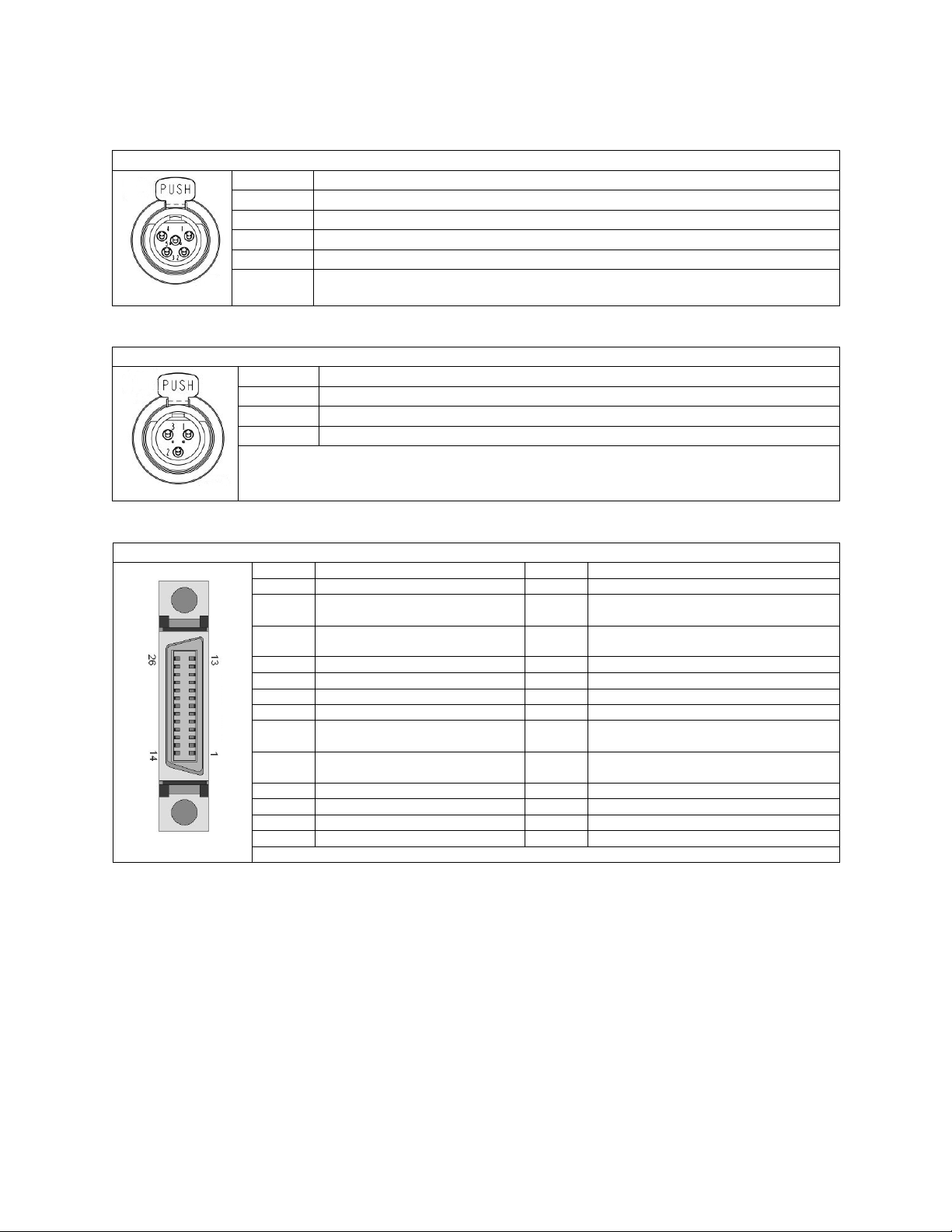
SilverBack V Camera-Mountable Fiber Optic Transmission System
© 2021 MultiDyne, Inc. Made in the USA Page
54
Connector Pinouts – Camera Unit
Intercom Headset Pinout
miniXLR-5F
Number
Description
1
GND
2
MIC Input+
3
GND
4
Audio L Output
5
Audio R Output
!
MIC/Line Audio Input (MIC 1 and MIC 2) Connector and Pinout
miniXLR-3F
Number
Description
1
GND
2
Input+
3
Input-
!
Four Channel Line Level I/O Connector (AUDIO I/O) and Pinout (26-Pin MDR)
MDR26-F
Number
Description
Number
Description
1
GND
14
GND
2
Ch1 Analog Audio Input-
or AES1 Input-
15
Ch1 Analog Audio Output+
or AES1 Output -
3
Ch1 Analog Audio Input+
or AES1 Input+
16
Ch1 Analog Audio Output-
or AES1 Output +
4
GND
17
GND
5
Ch2 Analog Audio Input+
18
Ch2 Analog Audio Output +
6
Ch2 Analog Audio Input-
19
Ch2 Analog Audio Output -
7
GND
20
GND
8
Ch3 Analog Audio Input+
or AES2 Input+
21
Ch3 Analog Audio Output +
or AES2 Output +
9
Ch3 Analog Audio Input-
or AES2 Input-
22
Ch3 Analog Audio Output -
or AES2 Output -
10
GND
23
GND
11
Ch4 Analog Audio Input+
24
Ch4 Analog Audio Output +
12
Ch4 Analog Audio Input-
25
Ch4 Analog Audio Output -
13
GND
26
GND
Follows MultiDyne VB Audio Series convention
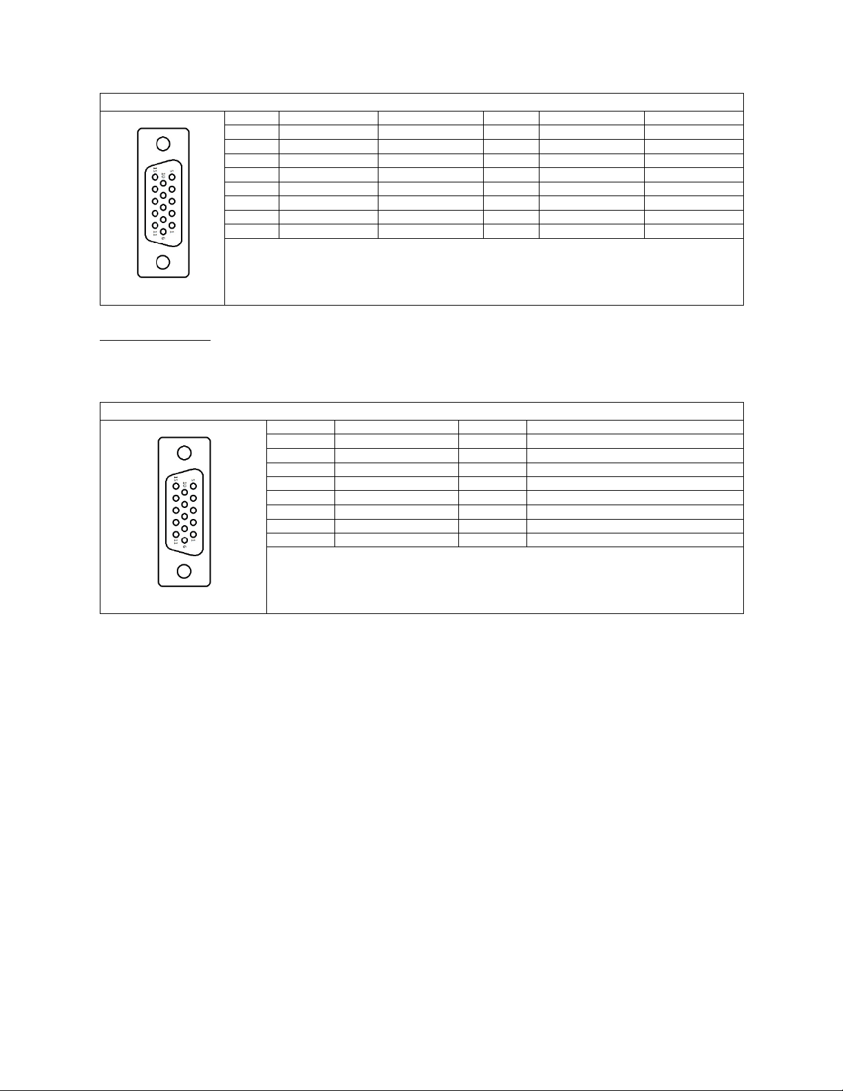
SilverBack V Camera-Mountable Fiber Optic Transmission System
© 2021 MultiDyne, Inc. Made in the USA Page
55
Camera Unit Serial Data Connector Pinout
HDB15-F
Number
RS422 Pinout
RS232 Pinout
Number
RS422 Pinout
RS232 Pinout
1
Data1 RXD In-
Data1 RXD
9
Data2 TTL Bias
N/C
2
Data1 RXD In+
N/C
10
GND
GND
3
N/C
Tie to GND
11
Data1 TXD Out-
Data1 TXD
4
Data2 RXD In-
Data2 RXD
12
Data1 TXD Out+
N/C
5
Data2 TXD Out+
N/C
13
N/C
N/C
6
Data1 TTL Bias
N/C
14
Data2 TXD Out-
Data2 TXD
7
GND
GND
15
Data2 RXD In+
N/C
8
N/C
Tie to GND
GPIO Connections
Your SilverBack V camera unit may be equipped with a GPIO port for interfacing with other devices
and/or controlling certain functions within the camera unit.
The GPIO functions are as follows:
• Generic GP input passed down to the base unit.
• Generic GP output passed up from the base unit (relay contact closure).
• Red tally output (relay contact closure).
• Green tally output (relay contact closure).
• Two headset MIC PTT GP inputs (one for each intercom channel).
• External Viewfinder Source Select GP input.
o Pin connected to Ground: Viewfinder will output return video.
o Pin open/disconnected: Viewfinder will output video signal connected to viewfinder
input.
• Generic GP input for controlling a camera unit function (future use).
Camera Unit GPIO Connector Pinout
HDB15-F
Number
Description
Number
Description
1
Red Tally Output
9
GND
2
Green Tally Output
10
GND
3
GPO 1 Output
11
Ch1 ICOM MIC Talk Trigger GPI Input
4
GPI 1 Input
12
Ch2 ICOM MIC Talk Trigger GPI Input
5
N/C
13
VF Input Select GPI Input
6
GND
14
Future Use GPI Input
7
GND
15
+12VDC Output, 1A Max
8
GND
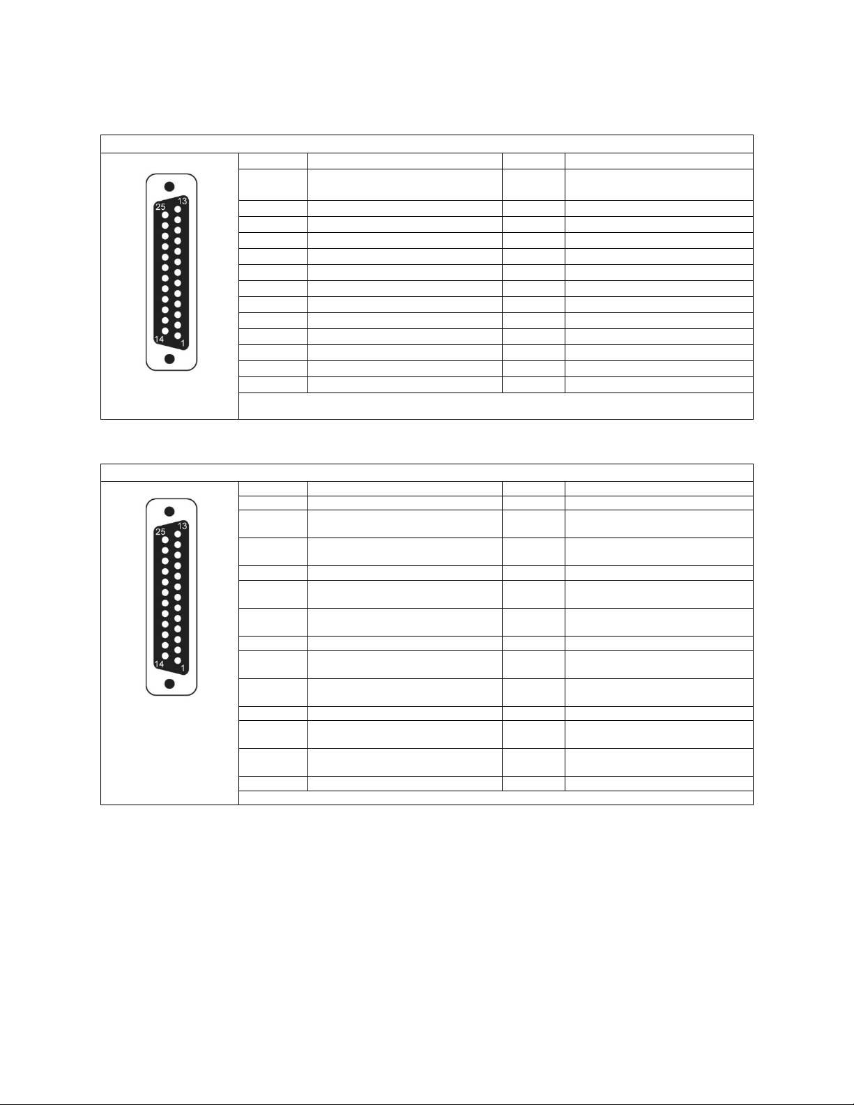
SilverBack V Camera-Mountable Fiber Optic Transmission System
© 2021 MultiDyne, Inc. Made in the USA Page
56
Connector Pinouts – Base Unit
Base Unit Intercom/GPIO Connector Pinout
DB25-F
Number
Description
Number
Description
1
2-Wire Intercom Pin2 (Ch1) or
4-Wire Intercom Ch1 Output+
14
2-Wire Intercom Pin3 (Ch2) or
4-Wire Intercom Ch2 Output+
2
4-Wire Intercom Ch1 Output-
15
4-Wire Intercom Ch2 Output-
3
GND
16
GND
4
4-Wire Intercom Ch1 Input+
17
4-Wire Intercom Ch2 Input+
5
4-Wire Intercom Ch1 Input-
18
4-Wire Intercom Ch2 Input-
6
PGM Audio Ch1 Input+
19
PGM Audio Ch2 Input+
7
PGM Audio Ch1 Input-
20
PGM Audio Ch2 Input-
8
GND
21
GND
9
GND
22
GPO Output 1
10
GPI Input 1
23
N/C
11
Red Tally GPI Input
24
Green Tally GPI Input
12
GND
25
GND
13
GND
Follows Sony/Panasonic CCU Convention
Base Unit Audio Connector Pinout
DB25-F
Number
Description
Number
Description
1
Ch4 Analog Audio Output+
14
Ch4 Analog Audio Output-
2
GND
15
Ch3 Analog Audio Output+
or AES2 Output+
3
Ch3 Analog Audio Output-
or AES2 Output-
16
GND
4
Ch2 Analog Audio Output+
17
Ch2 Analog Audio Output-
5
GND
18
Ch1 Analog Audio Output+
or AES1 Output+
6
Ch1 Analog Audio Output-
or AES1 Output-
19
GND
7
Ch4 Analog Audio Input+
20
Ch4 Analog Audio Input-
8
GND
21
Ch3 Analog Audio Input+
or AES2 Input+
9
Ch3 Analog Audio Input-
or AES2 Input-
22
GND
10
Ch2 Analog Audio Input+
23
Ch2 Analog Audio Input-
11
GND
24
Ch1 Analog Audio Input+
or AES1 Input+
12
Ch1 Analog Audio Input-
or AES1 Input-
25
GND
13
N/C
Follows Tascam convention
!
! !
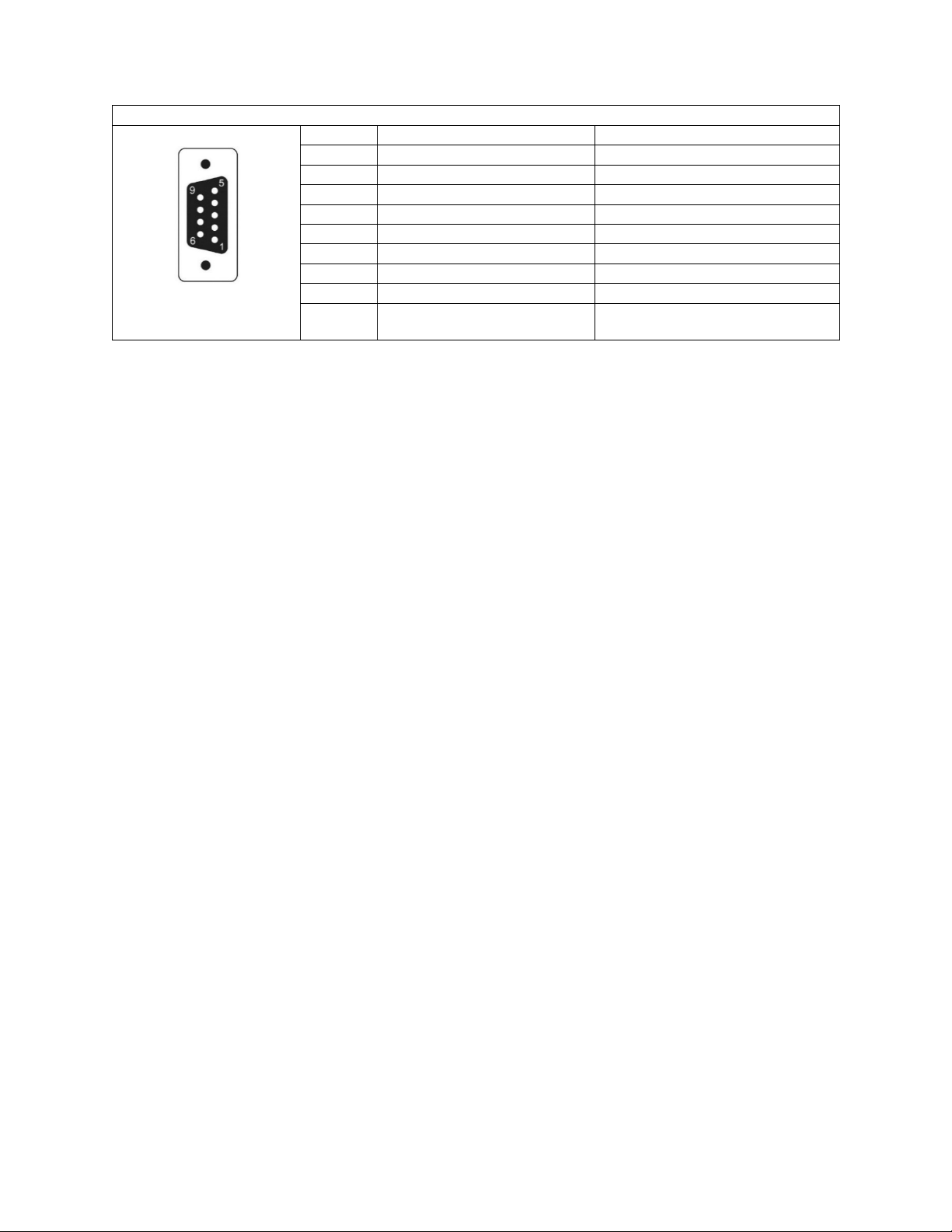
SilverBack V Camera-Mountable Fiber Optic Transmission System
© 2021 MultiDyne, Inc. Made in the USA Page
57
Base Unit Data Connector Pinout
DB-9F
Number
RS232 Pinout
RS422 Pinout
1
N/C
N/C (TTL Bias)
2
TXD Out
TXD Out -
3
RXD In
RXD In -
4
Tie to GND
N/C
5
GND
GND
6
N/C
N/C
7
N/C
TXD Out +
8
N/C
RXD In +
9
+12V Out
+12V Out

SilverBack V Camera-Mountable Fiber Optic Transmission System
© 2021 MultiDyne, Inc. Made in the USA Page
58
APPENDIX B - TROUBLESHOOTING
The following table consists of common symptom, probable cause, and test/corrective actions. The
probable cause column lists the most common faults that can occur with its corresponding symptom.
The test/corrective action column provides a reference to test procedures or specific repairs.
Symptom
Probable Cause
Test/Corrective Action
No power to system
Circuit breaker tripped
Verify that circuit breaker at power source
is on. Reset if necessary.
Operational settings are not in
synchronization between camera
unit and base unit
Camera unit and base unit
are not set up correctly
Reference operating procedures
No video
Dirty cable connection
Remove cable and clean both ends, as
described below
Defective video card
Contact MultiDyne
No audio, sync, or data functions
Dirty cable connection
Remove cable and clean both ends, as
described below
Defective circuit card
Contact MultiDyne
Cable Cleaning Procedure
CAUTION!
NEVER use isopropyl alcohol on any fiber connection. If not thoroughly cleaned and dry,
isopropyl alcohol can leave residual material on the fiber core, which can interrupt
signal flow.
Use only MultiDyne-recommended cleaning products designed for fiber optic cable
connections. MultiDyne recommends Sticklers Fiber Optic Connector Cleaner and
Benchtop Clean Wipes. For in-depth cleaning, MultiDyne recommends Bulkhead Ferrule
Cleaner tool.
Do not scrub the fiber against the wipe. This can cause scratches to the fiber connection.
In addition, do not reuse wipes as residual dirt can be transmitted to other cable
connections.
Use a fiberscope to inspect the LC connectors for dirt or damage.
• If cable connection is damaged, check the connection at both the camera unit and the base unit
• If cable connection is dirty:
o Fold a lint-free Sticklers Benchtop Clean Wipe into a square.
o Moisten one section of the wipe with a small amount of Sticklers Connector Cleaner.
o Lightly wipe the connector end.
o Dry using the other end of the wipe.
o Repeat this procedure using a fresh wipe for the other cables that need to be cleaned.
Re-inspect the LC connectors using a fiberscope to be sure connection has been cleaned.
For more in-depth cleaning, use the Bulkhead Ferrule Cleaner device.

SilverBack V Camera-Mountable Fiber Optic Transmission System
© 2021 MultiDyne, Inc. Made in the USA Page
59
• Make sure to use the correct size for the connector being cleaned.
• Prime the cleaner and place on the cable end to thoroughly clean the connection.
• Repeat this step for the other cables, as needed.

SilverBack V Camera-Mountable Fiber Optic Transmission System
© 2021 MultiDyne, Inc. Made in the USA Page
60
APPENDIX C - UPDATING SYSTEM SOFTWARE
Overview
The firmware update feature allows user to update the CPU and FPGA software through the use of a
microSD card without using any dedicated programmers. To use the SD card firmware update feature.
Turn off the SilverBack V, place the update file (.bin) for the desired system card onto the microSD card,
turn on the unit and navigate to the appropriate menu to perform the update process.
When updating a unit with multiple system cards of the same type, they will be updated automatically
one by one. Please allow the update process to finish completely before removing the power.
User menu input will be disabled for the duration of the software update and will be re-enabled when
software update is completed.
Note: Please only place one update file onto the SD card at a time.
For the SBV Base unit, Frame controller software Version 1.1.4 or higher is required to support software
updates.
For the SBV Camera unit, Main controller software Version 1.8 or higher is required to support software
updates.
For SBV FPGA updates and remote updates of the Camera unit from the Base unit, the following
software revisions are required:
Base Unit Frame Controller version 1.1.8
Base Unit Main Board version 1.0.17
Camera Unit Main Board version 2.1

SilverBack V Camera-Mountable Fiber Optic Transmission System
© 2021 MultiDyne, Inc. Made in the USA Page
61
Base Unit Update Process
This feature will update the cards in the SilverBack base unit through the microSD card. User has the
ability to individually update the two cameras.
To use the Silverback V Base Update feature:
• First, turn off the SilverBack V base unit
• Place the update file (.bin) onto the microSD card
• Insert the card into the SilverBack V base unit
• Turn on the unit
• Navigate to the base firmware update menu.
o To navigate to the base firmware update menu: Base Menu à Maintenance à Perform
System Update.
On the update screen, it will display the name of the file used in the update, the size of the file, the
intended card that will be updated and the current firmware version of the card/cards.
Select one of the cameras to update and the display will show “Update done” when the update process
is finished.
If the power supply software is being updated, Update Cam1 button will update the 12V and 48V power
supply for camera 1. Update Cam2 button will update the 12V and 48V power supply for camera 2.
If multiple cards of the same type are installed in each camera chain, e.g., 3G SDI cards, they will all be
updated automatically, one at a time.
Each CPU Software update takes around 2 minutes and each FPGA Firmware takes around 5 minutes. A
power cycle is recommended after performing any system updates.
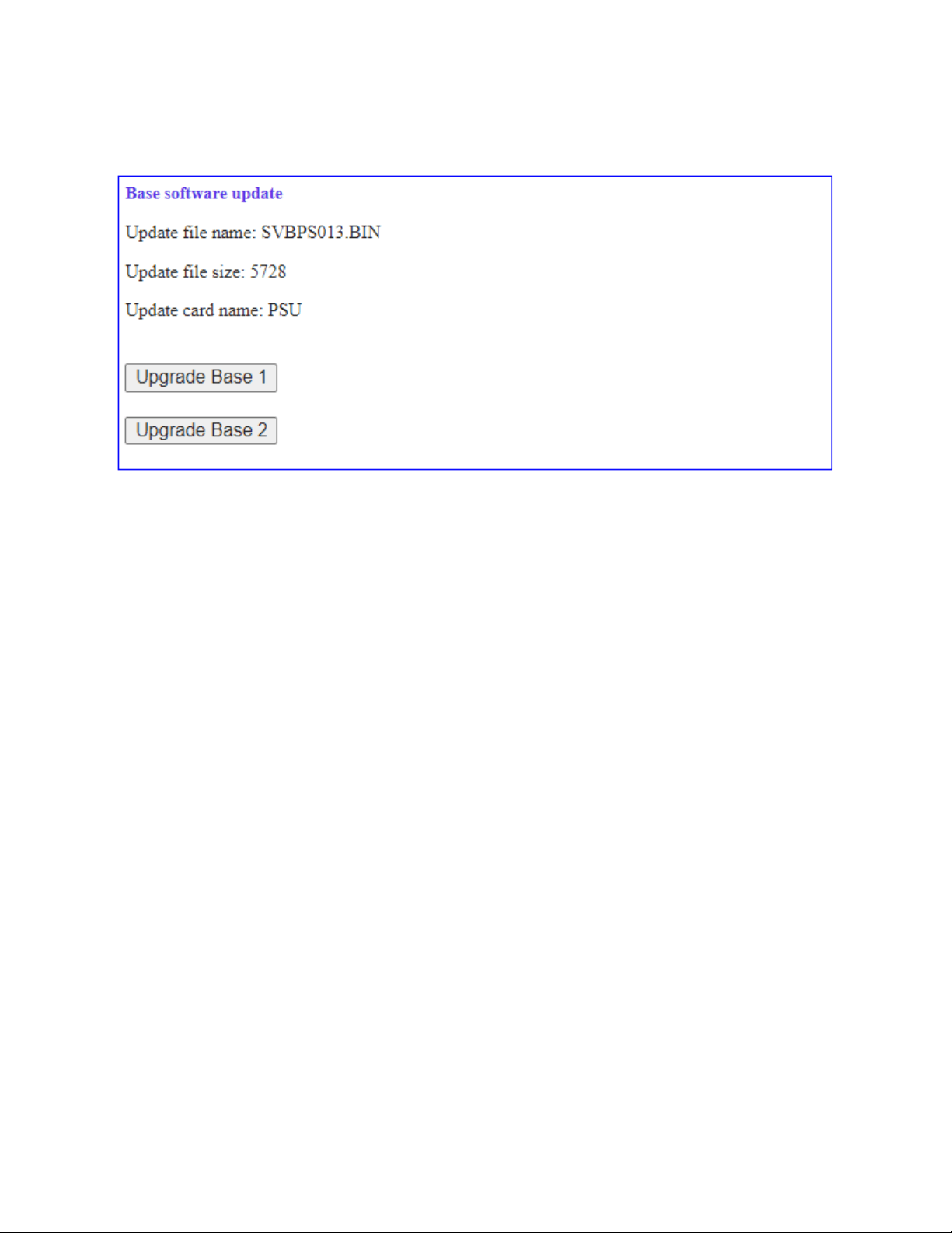
SilverBack V Camera-Mountable Fiber Optic Transmission System
© 2021 MultiDyne, Inc. Made in the USA Page
62
System software may also be updated from the webpage dashboard. The Base Software Update box can
be found on the webpage after the Base configuration settings.
The Base Frame Controller Software is updated using a different procedure, it cannot be updated from
the front panel menus or from the webpage dashboard.
To update the SBV base frame controller card:
• Turn off SilverBack V base unit.
• Remove the microSD card
• Place the update.bin file onto the microSD card.
• Insert the card into the SilverBack V base unit.
• Turn on the base unit.
The frame controller will automatically load the new software and boot from the new software.

SilverBack V Camera-Mountable Fiber Optic Transmission System
© 2021 MultiDyne, Inc. Made in the USA Page
63
Camera Unit Update Process
This feature will update the cards in the SilverBack V camera unit through the microSD card.
To use the Silverback V Camera Update Feature:
• First, turn off the SilverBack V camera unit
• Place the update file (.bin) onto the microSD card
• Insert the card into the SilverBack V camera unit
• Turn on the unit.
• Navigate to the camera firmware update menu.
o To navigate to the camera firmware update menu: System settings à Maintenance à
Card Update.
On the update screen, it will display the name of the card that will be updated, the update version and
the software version currently installed.
Select update to start the update process and it will show “Done” in green when the update process is
finished.
Each CPU Software update takes around 2 minutes and each FPGA Firmware update takes around 5
minutes.
SilverBack V remote camera update process
This feature allows user to update the software in the camera unit from the base unit. This is useful
when the camera is located in hard to reach places.
To use the Silverback V Remote Camera Update Feature:
• Turn off both SilverBack V camera and base unit
• Place the update file (.bin) onto the microSD card
• Insert the card into the SilverBack V base unit
• Turn on the units.
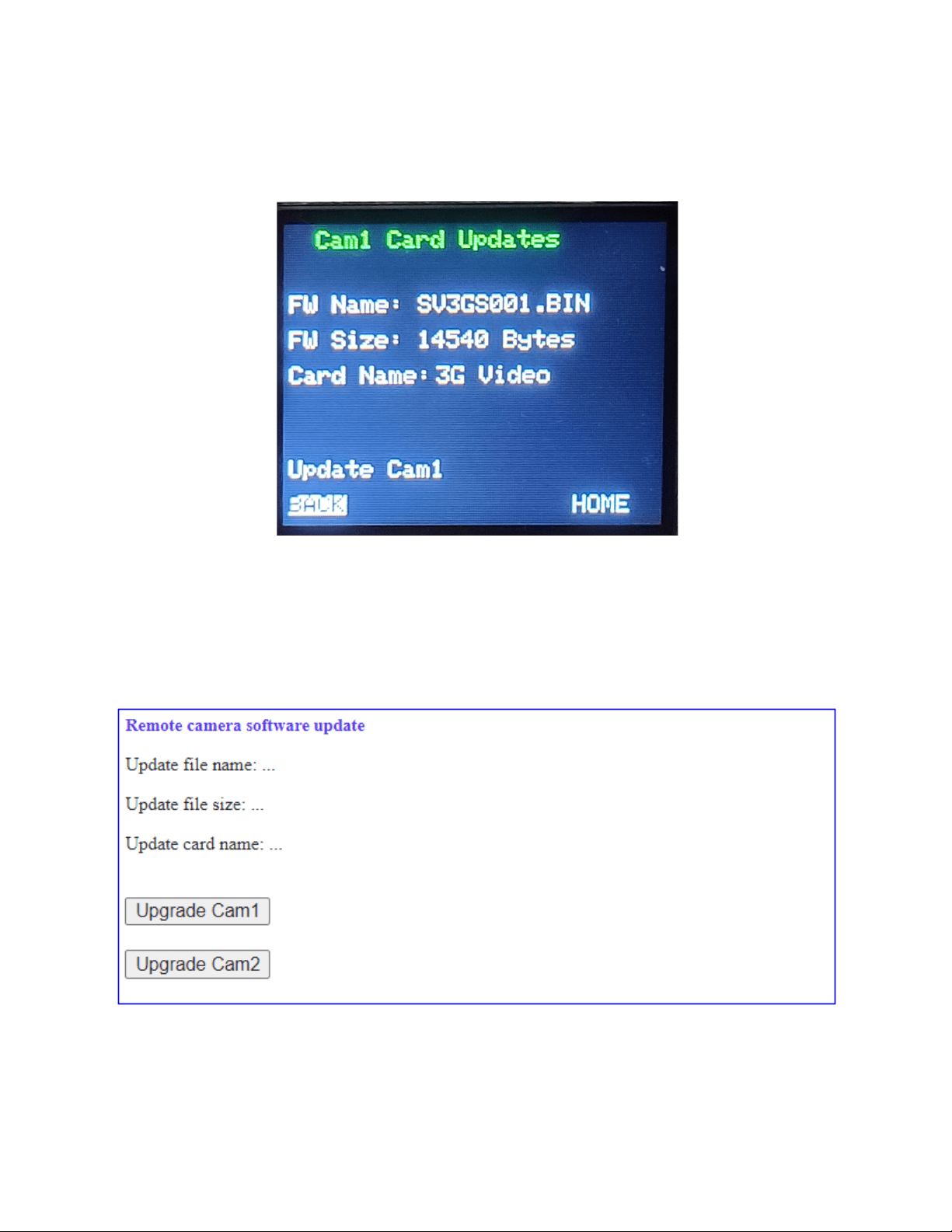
SilverBack V Camera-Mountable Fiber Optic Transmission System
© 2021 MultiDyne, Inc. Made in the USA Page
64
• Navigate to the remote camera firmware update menu in the Base Unit.
o To navigate to the base remote update menu: Cam Menu à Camera 1 OR Camera 2 à
Card Update.
On the update screen, it will display the name of the file used in the update, the size of the file and the
intended card that will be updated.
Remote Camera Unit software updates can also be invoked from the webpage dashboard instead of the
front panel menu. You can find the Remote Camera Software Update box on the webpage after the
Camera Remote Controls section.
Each remote Software update takes around 4 minutes to complete and each remote FPGA Firmware
update takes around 30 minutes due to messaging protocol overhead over the fiber.