Owner’s Manual &
Installation Manual
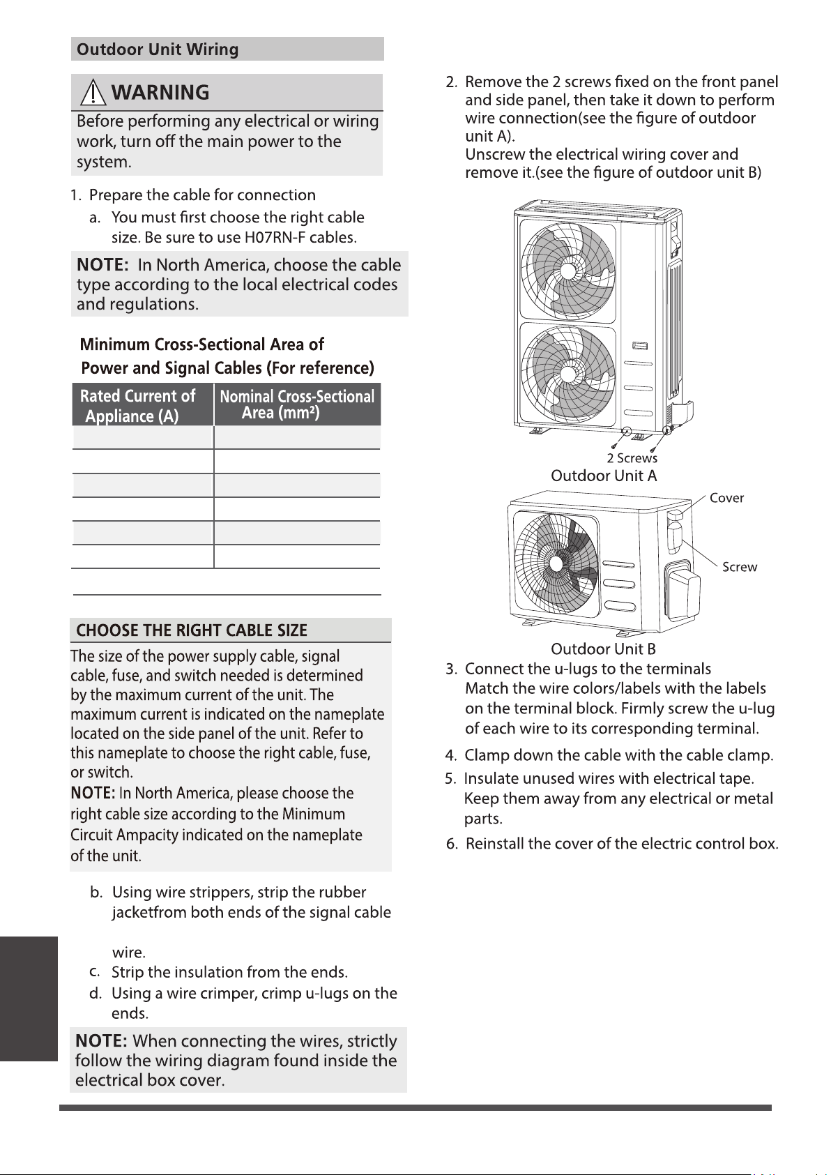
IMPORTANT NOTE:
• Read this manual carefully before installing
or operating your new air conditioning unit.
Make sure to save this manual for future reference.
One-way Cassette
MODEL
CH-06MCT1W-230VI
CH-09MCT1W-230VI
CH-12MCT1W-230VI
CH-18MCT1W-230VI

Unit Specications and Features
Owner’s Manual
Safety Precautions
Care and Maintenance
Troubleshooting
1. Unit Parts
2. Operating temperature
3. Features
4. Energy Saving Tips
.......................................................................................................................................................08
.........................................................................................................................09
.........................................................................................................................................................10
................................................................................................................................11
............................................................................04...................................
........................................................08
...........................
.........................................................................12
............................
...................................................................................15
..............................

Installation Manual
........................................................................................17
........................................................................................19
....................................................................20
....................................................................................................................20
...........................................................................................................................22
.....................................................................................................................25
.................................................................27
....................................................................................................................27
......................................................................................................................................28
................................................................................................................................28
........................................................................31
...............................................................................................................31
........................................................33
..................................................................................................36
....................................................................................................................................40
................................................................................................42
....................................................................................................................................43
....................................................................................................................43
......................................................................................................................................43
.......................................................................................................................45
................................................................................................................................46
Accessories
Unit Parts
Indoor Unit Installation
1. Select installation location
2. Indoor Unit Installation
3. Optinal parts installation
Outdoor Unit Installation
1. Select installation location
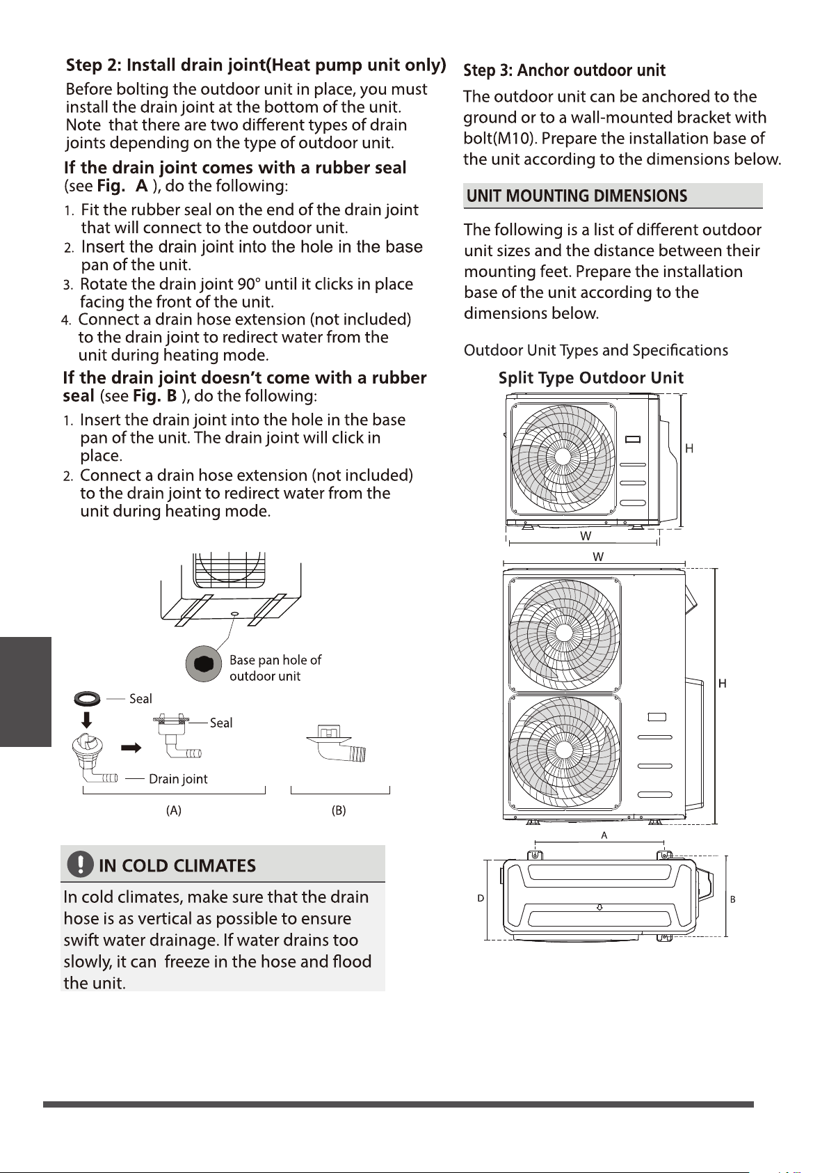
2. Install drain joint
3. Anchor outdoor unit
Drainpipe Installation
Indoor Drainpipe Installation
Refrigerant Piping Connection
Electrical Connections
Air Evacuation
Electrical and Gas Leak Chechs
Panel Installation
1. Prepare and install ceiling
2. Panel Installation
3. Optinal parts installation
Test Run
...................................
...................................
...................................
...................................
...................................
...................................
Page 4
Read Safety Precautions Before Operation and Installation
Incorrect installation due to ignoring instructions can cause serious damage or injury. The
seriousness of potential damage or injuries is classified as either a WARNING or CAUTION.
WARNING
• This appliance is not intended for use by persons(including children) with reduced physical,
sensory or mental capabilities, or lack of experience and knowledge, unless they have been
given supervision or instruction concerning use of the appliance by a person responsible for
their safety. Children should be supervised to ensure that they do not play with the appliance.
Safety Precautions
This symbol indicates the possibility of
personnel injury or loss of life.
This symbol indicates the possibility of
property damage or serious consequences.
WARNING
CAUTION
WARNINGS FOR PRODUCT USE
• If an abnormal situation arises (like a burning smell), immediately turn o the unit and
disconnect the power. Call your dealer for instructions to avoid electric shock, re or injury.
• Do not insert ngers, rods or other objects into the air inlet or outlet. This may cause injury,
since the fan may be rotating at high speeds.
• Do not use ammable sprays such as hair spray, lacquer or paint near the unit. This may cause
re or combustion.
• Do not operate the air conditioner in places near or around combustible gases. Emitted gas
may collect around the unit and cause explosion.
• Do not operate your air conditioner in a wet room such as a bathroom or laundry room. Too
much exposure to water can cause electrical components to short circuit.
• Do not expose your body directly to cool air for a prolonged period of time.
• Do not allow children to play with the air conditioner. Children must be supervised around
the unit at all times.
• If the air conditioner is used together with burners or other heating devices, thoroughly
ventilate the room to avoid oxygen deciency.
• In certain functional environments, such as kitchens, server rooms, etc., the use of specially
designed air-conditioning units is highly recommended.
• Toxic fumes may be produced if the refrigerant in this unit comes into contact with naked
ames (such as from a heater, gas stove/burners, or electric appliances).
Safety
Precautions
CLEANING AND MAINTENANCE WARNINGS
CAUTION
Safety
Precautions
WARNINGS FOR PRODUCT USE
Page 5
• Dispose of this unit’s packaging carefully, so children cannot playwith it. Packaging, especially
plastic packaging, can be dangerous, can cause serious injury or death. Screws, staples and other
metal packaging components can be sharp and should be disposed of carefully to avoid injury.
• Do not open or remove the unit's panel when the unit is powered on. Touching the unit's
internal components while the unit is powered on can lead to electric shocks or injuries caused
by moving parts such as the unit's fan.
• Do not spray any liquids onto the unit or allow any liquids to drip onto the unit.
• The refrigerant in this unit is safe and should not leak if the system is designed and installed
properly. However, if a large amount of refrigerant leaks into a room, the oxygen concentration
will decrease rapidly, which can cause serious injury or death. The refrigerant used in this unit
is heavier than air, so the danger is greater in basements or other underground spaces. In the
event of a refrigerant leak, turn o any devices that produce a naked ame and any heating
devices, ventilate the room, and contact your supplier or service engineer immediately.
• Turn o the device and disconnect the power before cleaning. Failure to do so can cause
electrical shock.
• Do not clean the air conditioner with excessive amounts of water
• Do not clean the air conditioner with combustible cleaning agents. Combustible cleaning
agents can cause re or deformation.
• Turn o the air conditioner and disconnect the power if you are not going to use it for a long time.
• Turn o and unplug the unit during storms.
• Make sure that water condensation can drain unhindered from the unit.
• Do not operate the air conditioner with wet hands. This may cause electric shock.
• Do not use device for any other purpose than its intended use.
• Do not climb onto or place objects on top of the outdoor unit.
• Do not allow the air conditioner to operate for long periods of time with doors or windows
open,or if the humidity is very high.
• Some parts of the unit are sharp and can cause injury if touched. To prevent injury, when the
unit is being serviced, gloves should be worn .
ELECTRICAL WARNINGS
• Only use the specified power cord. If the power cord is damaged, it must be replaced by the
manufacturer, its service agent or similarly qualied persons in order to avoid a hazard.
TAKE NOTE OF FUSE SPECIFICATIONS
The air conditioner’s circuit board (PCB) is designed with a fuse to provide overcurrent protection.
The specifications of the fuse are printed on the circuit board ,examples of such are T5A/250VAC
and T10A/250VAC.
Safety
Precautions
Page 6
ELECTRICAL WARNINGS
• Do not modify the length of the power supply cord or use an extension cord to power the unit.
• The product must be properly grounded at the time of installation, or electrical shock may occur.
• For all electrical work, follow all local and national wiring standards, regulations, and the
Installation Manual. Connect cables tightly, and clamp them securely to prevent external forces
from damaging the terminal. Improper electrical connections can overheat and cause re, and
mayalso cause shock. All electrical connections must be made according to the Electrical
Connection Diagram located on the panels of the indoor and outdoor units.
• All wiring must be properly arranged to ensure that the control board cover can close properly.
If the control board cover is not closed properly, it can lead to corrosion and cause the
connection points on the terminal to heat up, catch re, or cause electrical shock.
• Disconnection must be incorporated in the xed wiring in accordance with the wiring rules.
WARNINGS FOR PRODUCT INSTALLATION
• Installation must be performed by an
authorized dealer or specialist. Defective installation can
cause water leakage, electrical shock, or fire.
• Installation must be performed according to the installation instructions. Improper installation
can cause water leakage, electrical shock, or fire.
(In North America,installation must be performed in accordance with the requirement of NEC
and CEC by authorized personnel only.)
• Contact an authorized service technician for repair or maintenance of this unit. This appliance
shall be installed in accordance with national wiring regulations.
• Only use the included accessories, parts, and specified parts for installation. Using non-standard
parts can cause water leakage, electrical shock, fire, and can cause the unit to fail.
• Install the unit in a firm location that can support the unit’s weight. If the chosen location can
not support the unit’s weight, or the installation is not done properly, the unit may drop and
cause serious injury and damage
• Install drainage piping according to the instructions in this manual. Improper drainage may
cause water damage to your home and property
• For units that have an auxiliary electric heater, do not install the unit within 3 feet (1 meter) of
any combustible materials
• Do not install the unit in a location that may be exposed to combustible gas leaks. If
combustible gas accumulates around the unit, it may cause fire.
• Do not turn on the power until all work has been completed.

Page 7
ELECTRICAL WARNINGS
• When moving or relocating the air conditioner, consult experienced service technicians for
disconnection and reinstallation of the unit.
• How to install the appliance to its support, please read the information for details in "indoor
unit installation" and "outdoor unit installation" sections .
Safety
Precautions
Page 8
Unit Specications and Features
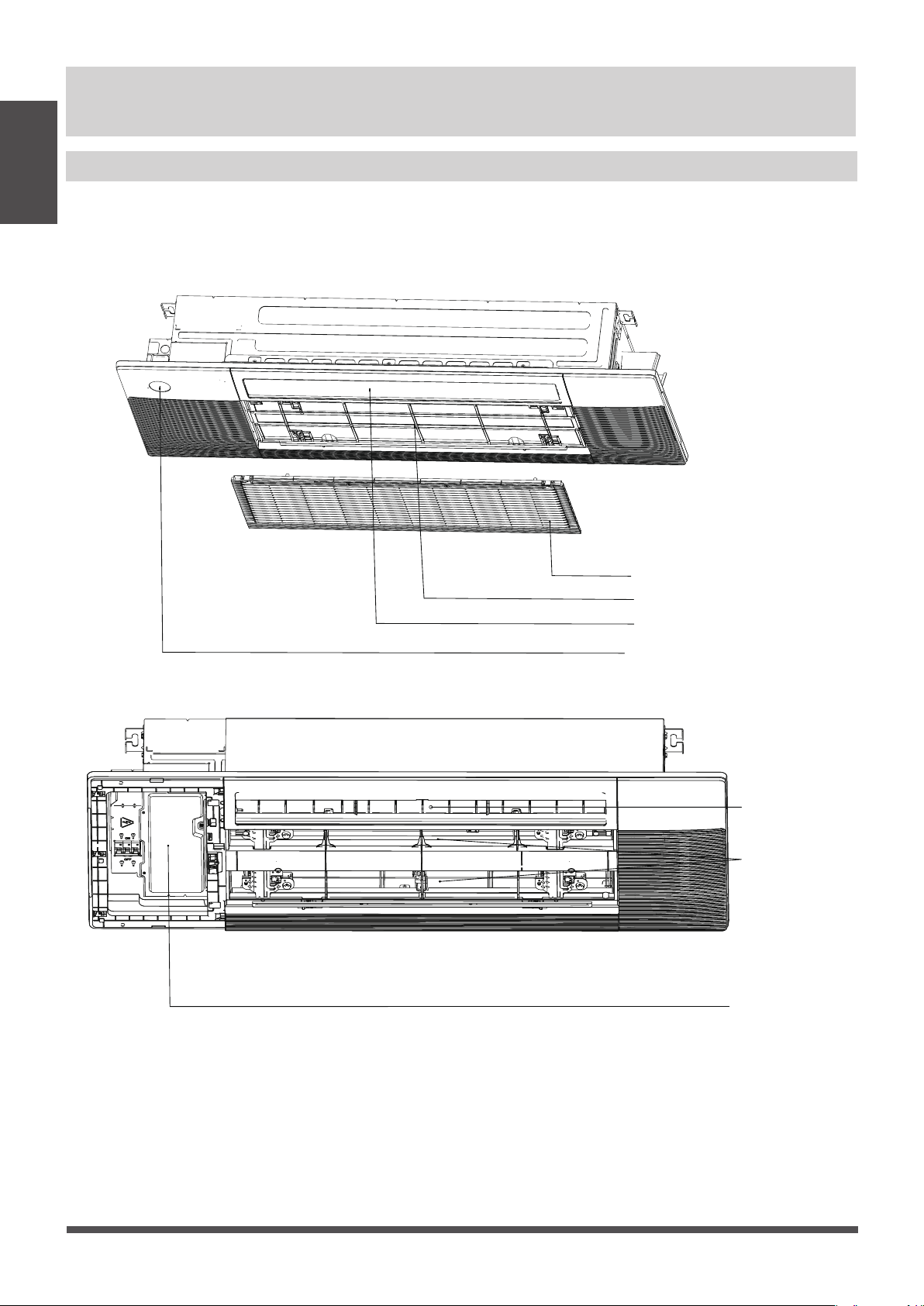
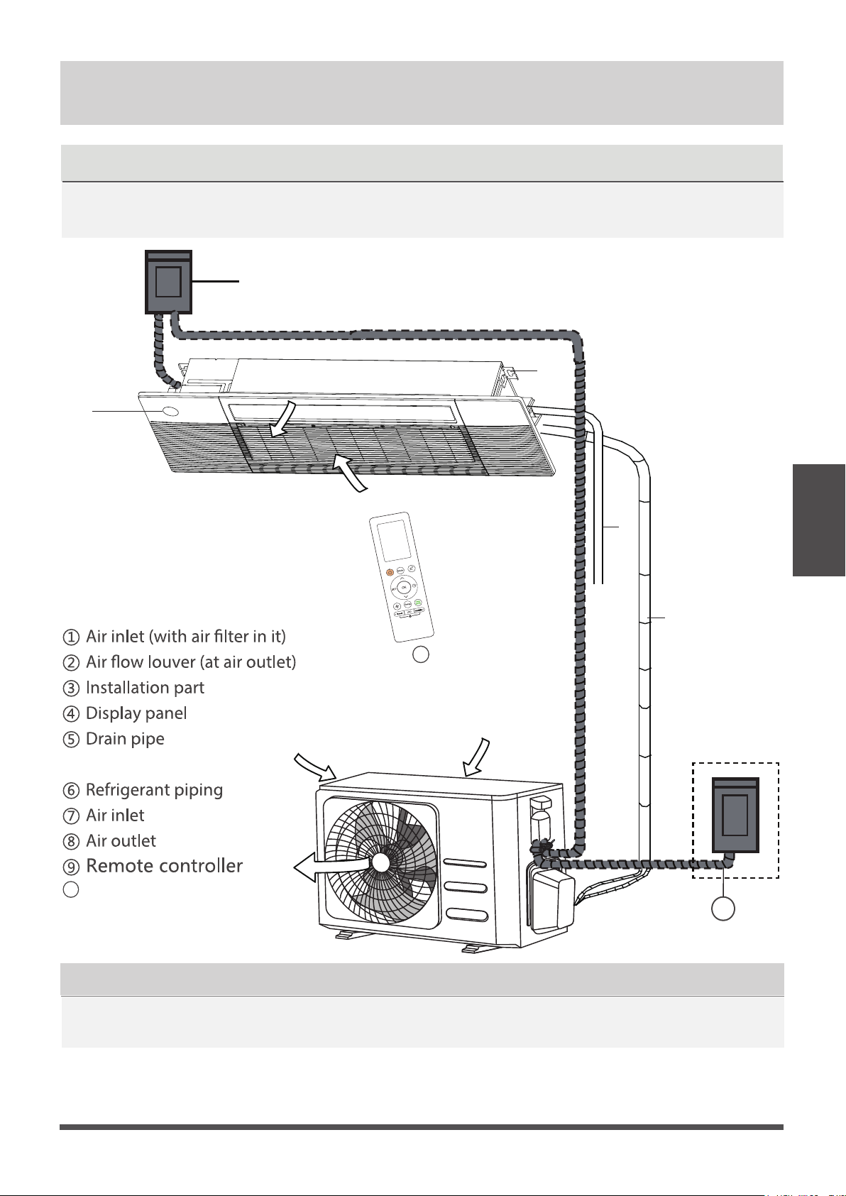
NOTE: Illustrations in this manual are for explanatory purposes. The actual shape of your indoor
unit may be slightly dierent. The actual shape shall prevail.
Unit Parts
Unit Specications
and Features
Air Intake Grille
Air Filter
Air Vane
Display Panel
Air Outlet
Air Inlet
Electronic Control Box
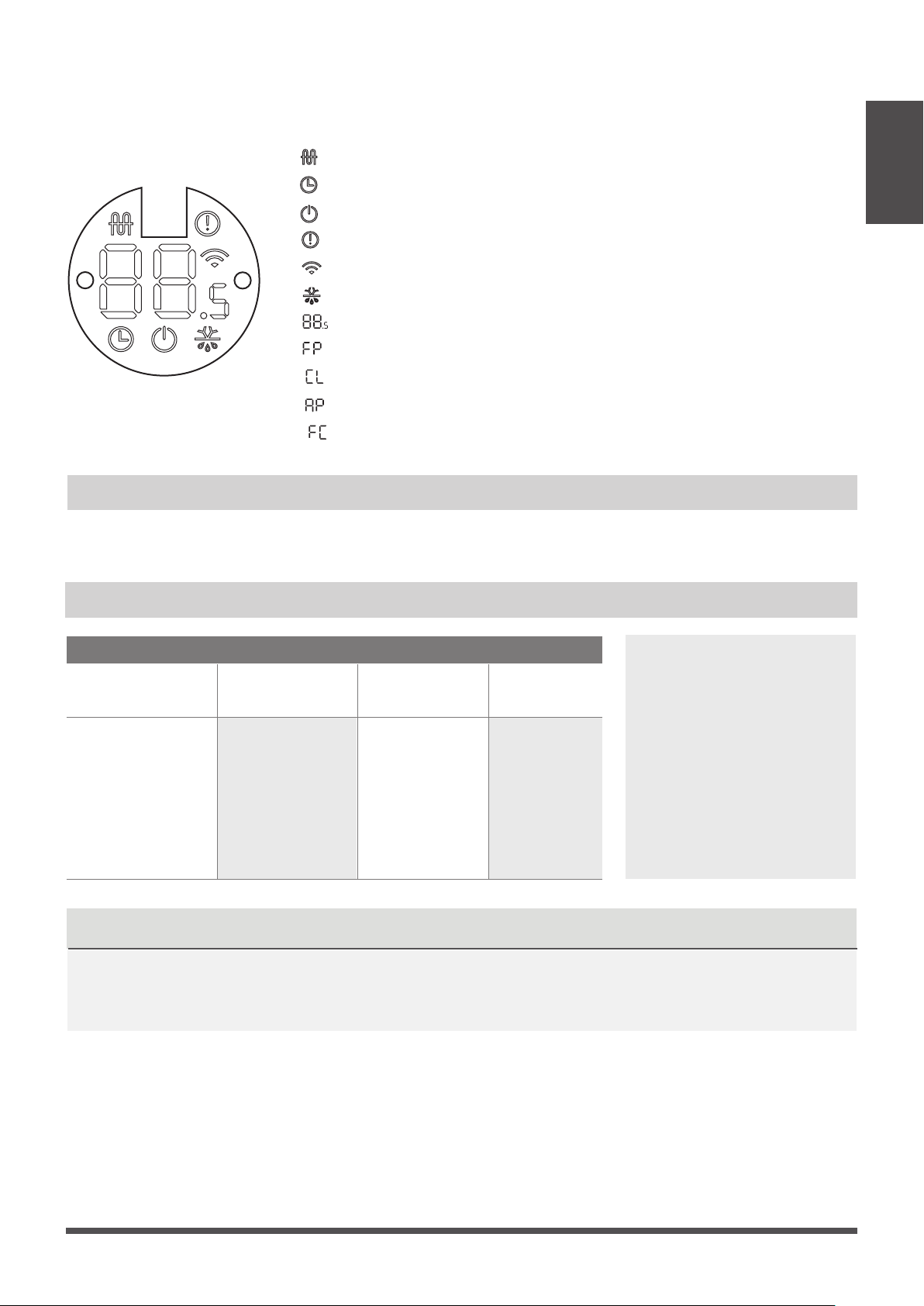
“ ” when Electric heating feature is activated (Not available for this unit)
“ ” when TIMER is set.
“ ” when the unit is on.
“ ”
Alarm indicator.
“ ” when Wireless Control feature is activated(some units)
“ ” when
pre-heating/defrost feature is activated.
Page 9
The display panel has one type and the appearance of the type is shown in below.
Display panel
Operating temperature
When your air conditioner is used outside of the following temperature ranges, certain safety
protection features may activate and cause the unit to disable.
COOL mode HEAT mode DRY mode
Room Temperature
(16°C - 32°C)
61°F - 90°F
(0°C - 30°C)
32°F - 86°F
(10°C - 32°C)
50°F - 90°F
Outdoor
Temperature
-13°F - 75°F
(-25°C - 24°C
)
(0°C - 50°C)
32°F - 122°F
-13°F - 122°F
(
-25°C - 50°C)
Inverter Split Type
FOR OUTDOOR UNITS
WITH AUXILIARY
ELECTRIC HEATER
When outside
temperature is below
32°F (0°C ), we strongly
recommend keeping the
unit plugged in at all
time to ensure smooth
ongoing performance.
Unit Specications
and Features
NOTICENOTICE
Displays temperature, operation feature and Error codes:
“ ”
“ ” when Active Clean feature is turned on
“ ” when WiFi module enters AP mode
(some units)
“ ” when Forced cooling feature is turned on
“ ” when 8℃ heating feature is turned on
Room relative humidity less than 80%. If the air conditioner operates in excess of this gure,
the surface of the air conditioner may attract condensation. Please sets the vertical air ow
louver to its maximum angle (vertically to the oor), and set HIGH fan mode.
Page 10
• Keep doors and windows closed.
• Limit energy usage by using TIMER ON and TIMER OFF functions.
• Do not block air inlets or outlets.
• Regularly inspect and clean air lters.
To further optimize the performance of your unit, do the following:
Features
Unit Specications
and Features
Louver Angle Memory Function
Some models are designed with a louver angle
memory function. When the unit restarts after
a power failure, the angle of the horizontal
louvers will automatically return to the previous
position.
The angle of the horizontal louver should not
be set too small as condensation may form and
drip into the machine. To reset the louver, press
the manual button, which will reset the
horizontal louver settings.
Default Setting
When the air conditioner restarts after a power
failure, it will default to the factory settings
(AUTO mode, AUTO fan, 76°F(24°C). This may
cause inconsistencies on the remote control
and unit panel. Use your remote control to
update the status.
Auto-Restart
In case of power failure, the system will
immediately stop. When power returns, the
Operation light on the indoor unit will flash. To
restart the unit, press the ON/OFF button on
the remote control. If the system has an auto
restart function, the unit will restart using the
same settings.
Three-minute protection feature
A protection feature prevents the air
conditioner from being activated for
approximately 3 minutes when it restarts
immediately after operation.
Set
temperature
1hr
Keep
running
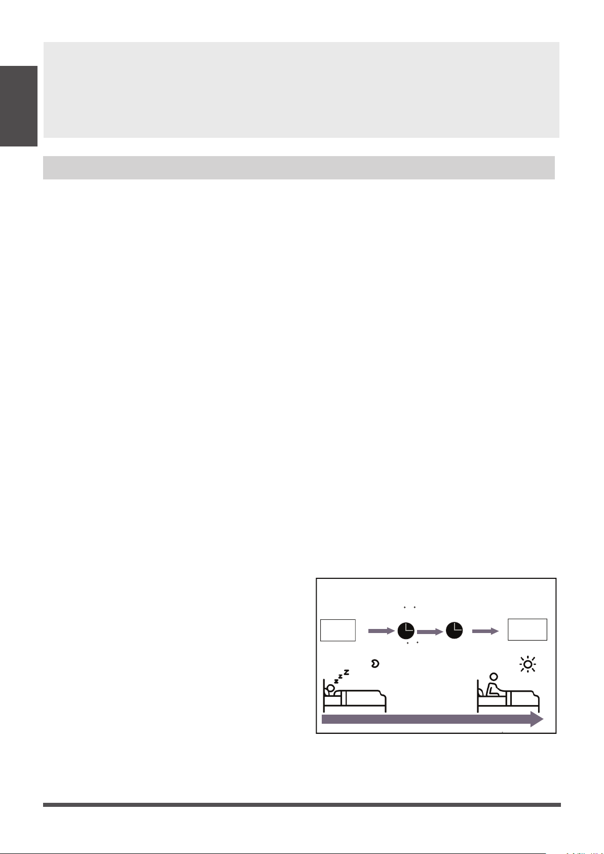
SLEEP Operation
Saving energy during sleep
Heat mode(2 F/-1 C) per hour
for the first two hours
Cool mode(2 F/+1 C) per hour
for the first two hours
1hr
system will keep running with nal situation.
Refrigerant Leak Detection System
(Multi-Zone Systems models do not have this
function)
In the event of a refrigerant leak, the LED
DISPLAY will display refrigerant leak error code
and the LED indicator light will flash.
Sleep Operation
The SLEEP function is used to decrease energy
use while you sleep (and don’t need the same
temperature settings to stay comfortable). This
function can only be activated via remote control.
And the Sleep function is not available in FAN or
DRY mode.
Press the SLEEP button when you are ready to
go to sleep. When in COOL mode, the unit will
increase the temperature by 2°F
(1°C) after 1 hour,
and will increase an additional 2°F (1°C) after
another hour.
When in HEAT mode, the unit will decrease the
temperature by 2°F (1°C) after 1 hour, and will
decrease an additional 2°F (1°C)after another hour.
The sleep feature will stop after 8 hours and the

In the stand-by mode, press the “Mode” and
“Down” buttons for 3 seconds at the same time,
the remote controller enters the setting panel
state, and the remote controller displays "F2".
When setting the panel status, press the “Up”
or “Down” buttons of the remote controller to
control the rise or fall of the grille, and press any
other button to exit the setting.
Lifting panel operation
Unit Specications
and Features
Active Clean function (Multi-Zone Systems models
do not have this function)
The Active Clean Technology washes away
dust when it adheres to the heat exchanger by
automatically freezing and then rapidly thawing
the frost. A double beep sound will be heard.
The Active clean operation is used to produce
more condensed water to improve the cleaning
eect, and the cold air will blow out. After
cleaning, the internal wind wheel then keeps
operating with hot air to blow-dry the evaporator,
thus keeping the inside clean.
- When this function is turned on, the indoor
unit display window appears “CL ” , after 20 to
130 minutes, the unit will turn o automatically
and cancel Active Clean function.
- For some units, the system will start high
temperature cleaning process, and the
temperature of air outlet is very high.
Please keep away from it. And this would lead
to the rising of the room temperature .
Page 11
• DO NOT set the unit to excessive temperature levels.
• While cooling, close the curtains to avoid direct sunlight.
• Doors and windows should be kept closed to keep cool or warm air in the room.
• DO NOT place objects near the air inlet and outlet of the unit.
• Clean the air lter every two weeks.
• Adjust louvers properly and avoid direct airflow.
• Closing curtains during heating also helps keep the heat in.
• Doors and windows should be kept closed.
Energy Saving Tips
The up and down height of the panel can
reach a maximum of 1.5 meters. During the
decline, if the grille is raised by the obstacles,
it will stop. During the ascending process, if
the grille is blocked and does not rise to the
correct height or a nger is pinched, it will
automatically descend after a period of time
and then ascend. If the grille is bocked for the
third times, then the display panel will report
an error and prompt for manual processing.
Breeze Away
This feature avoids direct air ow blowing on
the body and make you feel indulging in
silky coolness.
NOTICE
NOTICE
In households with animals, you will have
to periodically wipe down the grille to
prevent animal hair blocking airow.
• Contact an authorized service technician for
repair or maintenance. Improper repair and
maintenance may cause water leakage,
electrical shock, or re, and may void your
warranty.
• DO NOT substitute a blown fuse with a higher
or lower amperage rating fuse, as this may
cause circuit damage or an electrical re.
• Make sure the drain hose is set up according
to the instructions. Failure to do so could cause
leakage and result in personal property damage,
re and electric shock.
• Make sure that all wires are connected properly.
Failure to connect wires according to instructions
can result in electrical shock or re.
Care and Maintenance
BEFORE CLEANING OR MAINTENANCE
REMEMBER TO DISCONNECT THE POWER BEFORE
CLEANING OR MAINTENANCE, EXCEPT FOR CLEANING
AIR FILTER.TURN THE CURCUIT BREAKER OF THE INDOOR
UNIT TO OFF IS NOT A KIND OF POWER DISCONNECTION.
CAUTION
Cleaning Your Indoor Unit
• Only use a soft, dry cloth
to wipe the unit
clean. If the unit is especially dirty, you can use
a clothsoaked in warm water to wipe it clean.
• Do not use chemicals or chemically treated
cloths to clean the unit.
• Do not use benzene, paint thinner,polishing
powder or other solvents to clean the unit.
They can cause the plastic surface to crack or
deform.
• Do not use water hotter than 104°F (40°C) to
clean the front panel. This can cause the panel
to deform or become discolored.
• DO NOT wash the unit under running water.
Doing so creates an electrical hazard. Clean
the unit using a damp, lint-free cloth and
neutral detergent. Dry the unit with a dry,
lint-free cloth.
WARNING: DO NOT REMOVE OR
CLEAN THE FILTER BY YOURSELF
Removing and cleaning the filter can be
dangerous. Removal and maintenance must
be performed by a certified technician.
Cleaning Your Air Filter
The lter prevents dust and other particles from
entering the indoor unit. Dust buildup can reduce
the eciency of the air conditioner. For optimum
eciency, clean the air lter every two weeks or
more frequently if you live in a dusty area.
Replace the lter with a new one if it’s heavily
clogged and cannot be cleaned.
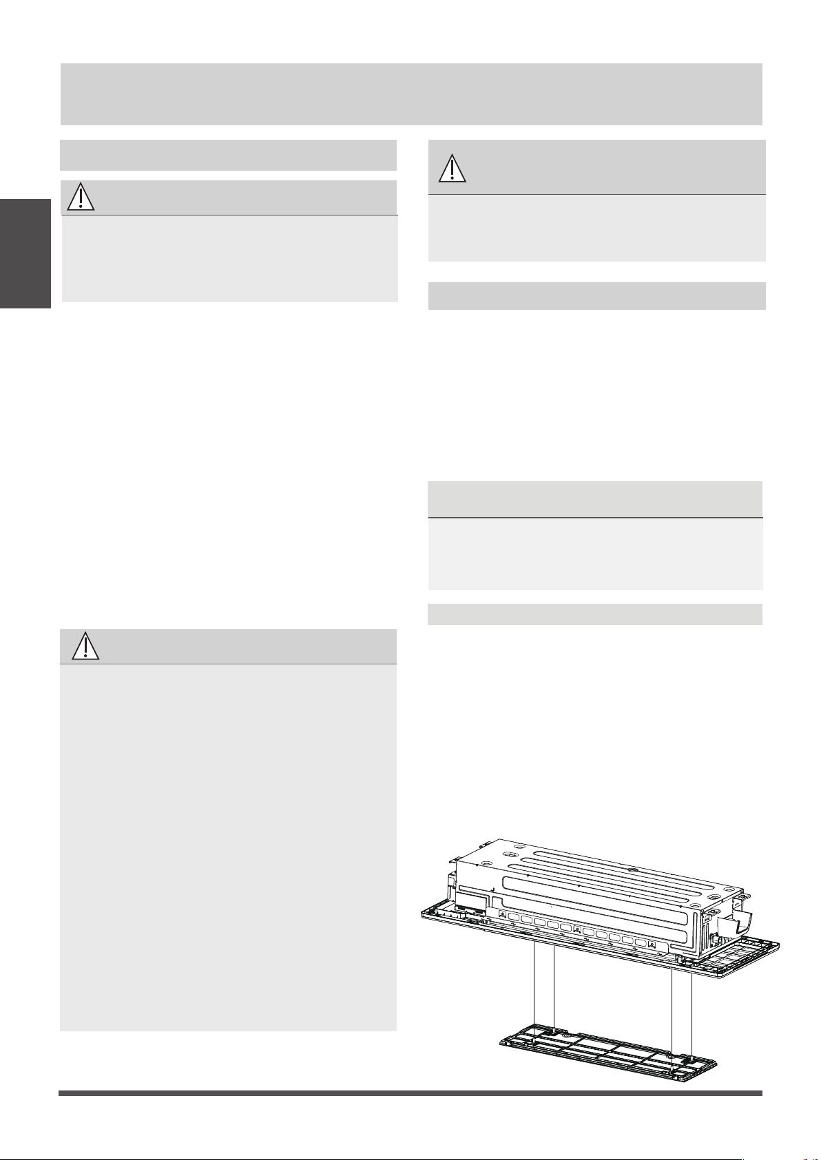
Model A
1. In the stand-by mode, press the “MODE” and
“DOWN” buttons on the remote controller at
the same time for 3 seconds, the remote
controller enters the panel-setting state, the
remote controller displays "F2".
2. Then press “DOWN” button on the remote
controller, the air grille automatically goes down.
When it stops, pick up the air lter.
Page 12
Care and
Maintenance
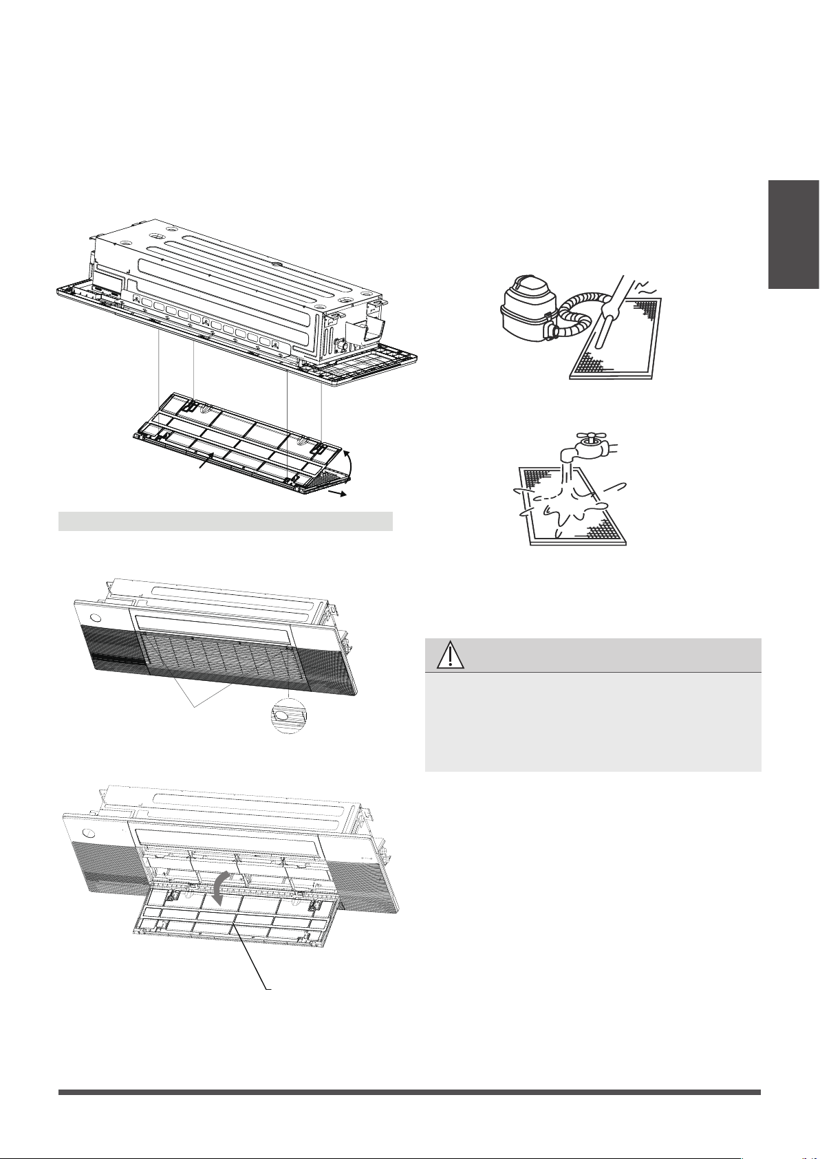
a. The air intake side should face up when using
a vacuum cleaner.
b. The air intake side should face down when
using clean water.
For excessive dusts, use a soft brush and natural
detergent to clean it and dry in a cool place.
CAUTION
4. Re-install the air lter.
5. Press “UP” button on the remote controller to
reset the air grille. (Applicable to model A)
Re-install the air grille by xing the two screws
and close the two screw covers.
(Applicable to model B)
• Do not dry out the air lter under direct
sunshine or with re.
• The air lter should be installed before the
unit body installation.
a. Hold the upper edge of the lter with both
hands. Gently turn and lift until the upper edge
is free from the wire rope.
b. Lift the lter and move it forward slightly until
the lter is separated from the 4 wire ropes.
c. Move the lter to the right until it is separated
from the air grille , and then the lter can be
taken out.
a
b
c
Page 13
Care and
Maintenance
3. Clean the air lter
Dusts will accumulate on the lter along with
the unit operation, and need to be removed from
the lter,or the unit would not function eectively.
Clean the lter every two weeks when you use
the unit regularly.
Clean the air lter with a vacuum cleaner or
water.
Model B
1. Press the circular positon to open the two
screw covers, then remove the two screws.
2.Hold and open the air grille, then take out the
air lter.
Screw Cover
air lter
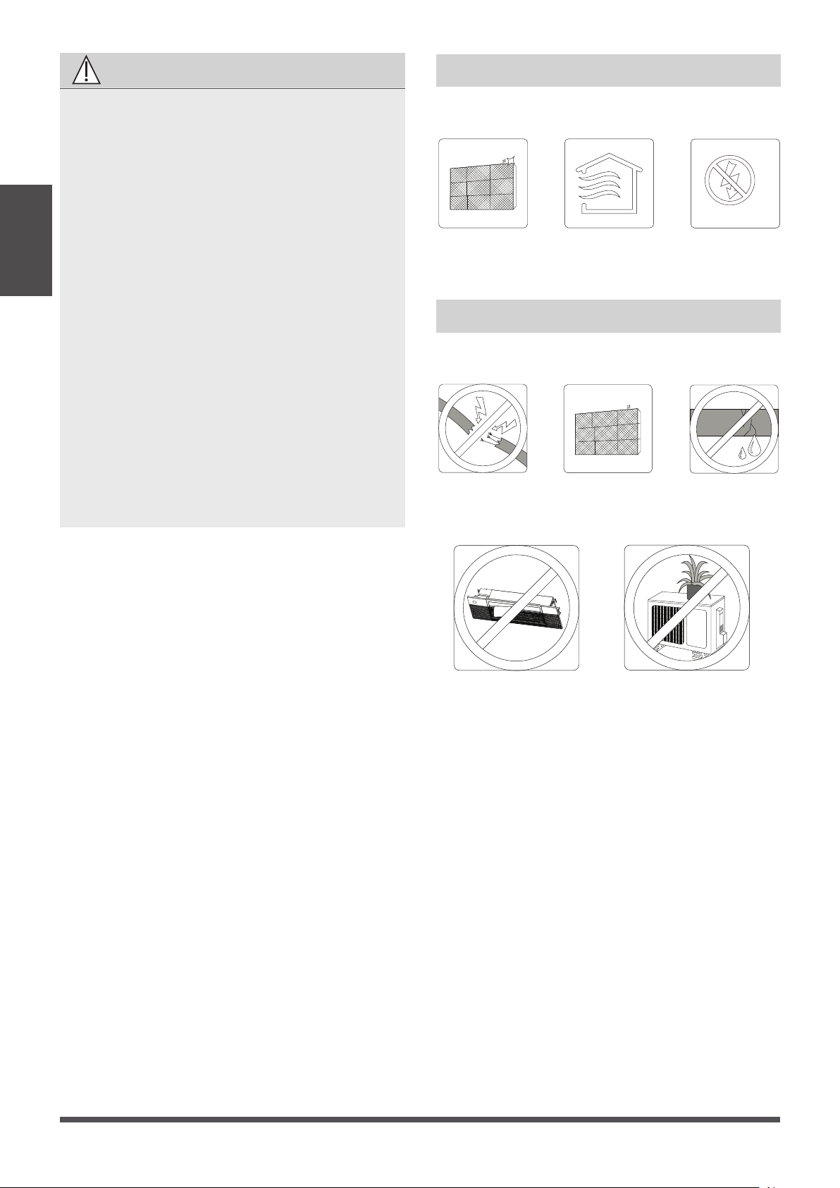
CAUTION
• Before changing the lter or cleaning, turn
o the unit .
• When removing lter, do not touch metal
parts in the unit. The sharp metal edges can
hurt you.
• Do not use water to clean the inside of the
indoor unit. This can destroy insulation and
cause electrical shock.
• Do not expose lter to direct sunlight when
drying. This can shrink the lter.
• Any maintenance and cleaning of outdoor
unit should be performed by an authorized
dealer or a licensed service provider.
• Any unit repairs should be performed by an
authorized dealer or a licensed service
provider.
• When the air grille is rising, please do not
hinder the grille from rising with your hands
or other objects.
Please do not pull the wire rope, if necessary,
please contact the local customer service
team.
Care and
Maintenance
Maintenance – Long Periods of Non-Use
If you plan not to use your air conditioner for an
extended period of time, do the following:
Maintenance – Pre-Season Inspection
After long periods of non-use, or before periods
of frequent use, do the following:
Check for
damaged wires
Clean all lters
Check for leaks
Make sure nothing is blocking all air inlets and outlets
Clean all lters
Turn on FAN function until
unit dries out completely
Turn o the unit and
disconnect the power
Page 14
•
Troubleshooting
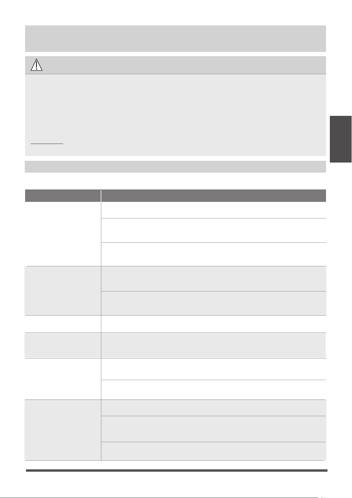
Common Issues
The following problems are not a malfunction and in most situations will not require repairs.
Issue Possible Causes
Unit does not turn
on when pressing
ON/OFF button
The Unit has a 3-minute protection feature that prevents the unit from overloading.
The unit cannot be restarted within three minutes of being turned o.
The unit may change its setting to prevent frost from forming on the unit.
Once the temperature increases, the unit will start operating in the
previously selected mode again.
The set temperature has been reached, at which point the unit turns o the
compressor. The unit will continue operating when the temperature
fluctuates again.
The indoor unit
emits white mist
In humid regions, a large temperature dierence between the room’s air
and the conditioned air can cause white mist.
Both the indoor and
outdoor units emit
white mist
When the unit restarts in HEAT mode after defrosting, white mist may be
emitted due to moisture generated from the defrosting process.
The unit changes from
COOL/HEAT mode to
FAN mode
The indoor unit makes
noises
A squeaking sound may occur after running the unit in HEAT mode due to
expansion and contraction of the unit’s plastic parts.
Both the indoor unit
and outdoor unit make
noises
Low hissing sound during operation: This is normal and is caused by refrigerant
gas flowing through both indoor and outdoor units.
Low hissing sound when the system starts, has just stopped running, or is
defrosting: This noise is normal and is caused by the refrigerant gas stopping or
changing direction.
Squeaking sound: Normal expansion and contraction of plastic and metal parts
caused by temperature changes during operation can cause squeaking noises.
SAFETY PRECAUTIONS
If any of the following conditions occurs, turn o your unit immediately!
DO NOT ATTEMPT TO FIX THESE YOURSELF! CONTACT AN AUTHORIZED
SERVICE PROVIDER IMMEDIATELY!
Cooling and Heating Models: If the Operation light and PRE-DEF (Pre-heating/
Defrost) indicators are lit up, the outdoor temperature is too cold and the unit’s
anti-cold wind is activated in order to defrost the unit.
In Cooling-only Models: If the “Fan Only” indicator is lit up, the outdoor
temperature is too cold and the unit’s anti-freeze protection is activated in
order to defrost the unit.
A squeaking sound is heard when the system is OFF or in COOL mode. The
noise is also heard when the drain pump (optional) is in operation.
Troubleshooting
• The power cord is damaged or abnormally warm.
• You smell a burning odor.
• The unit emits loud or abnormal sounds.
• A power fuse blows or the circuit breaker frequently trips.
• Water or other objects fall into or out of the unit.
Page 15
Issue Possible Causes
The outdoor unit
makes noises
The unit will make dierent sounds based on its current operating mode.
Dust is emitted from
either the indoor or
outdoor unit
The unit may accumulate dust during extended periods of non-use, which will be
emitted when the unit is turned on. This can be mitigated by covering the unit during
long periods of inactivity.
The unit emits a
bad odor
The unit may absorb odors from the environment (such as furniture, cooking,
cigarettes, etc.) which will be emitted during operations.
The unit’s filters have become moldy and should be cleaned.
The fan of the outdoor
unit does not operate
During operation, the fan speed is controlled to optimize product operation.
NOTE:
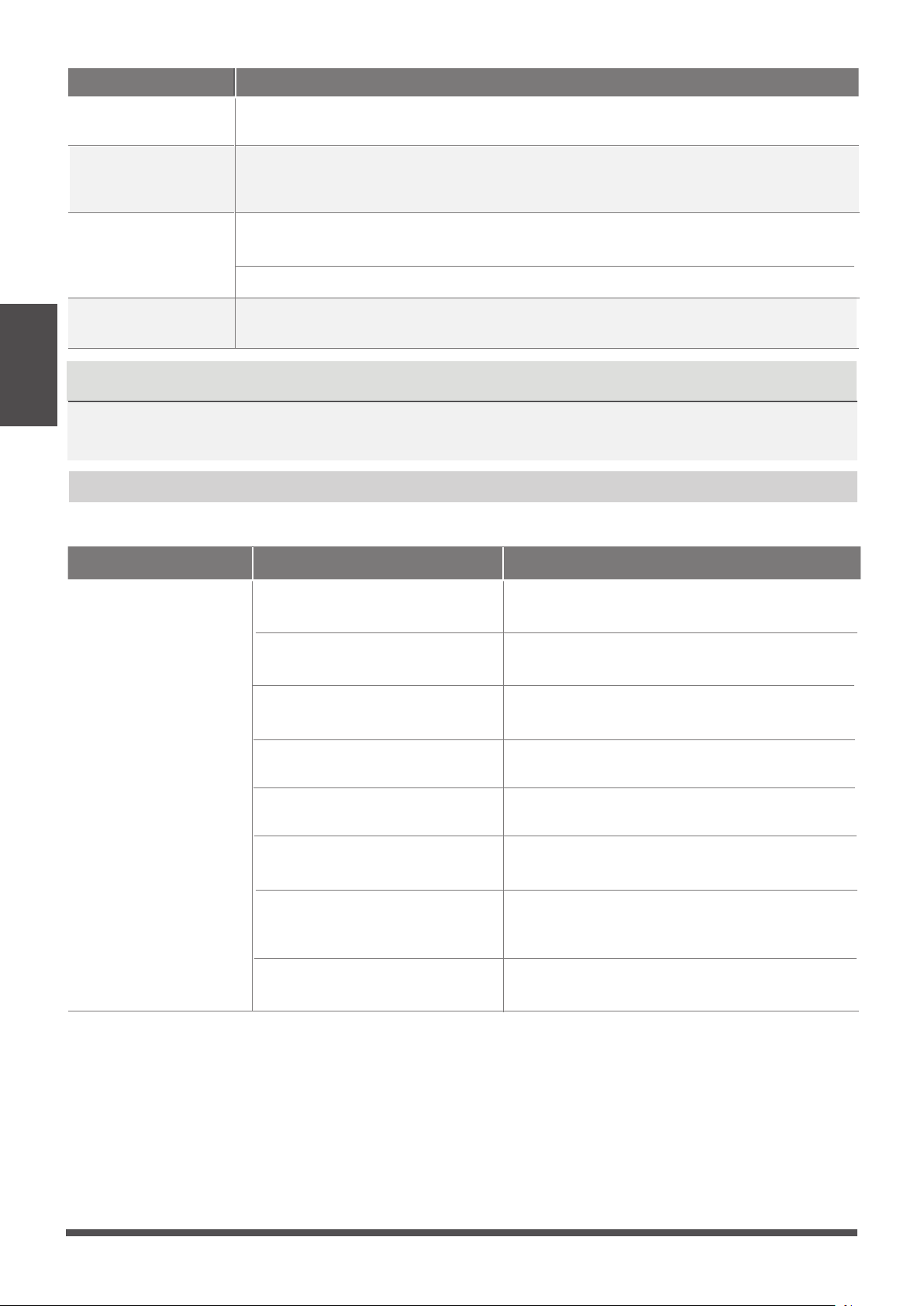
Troubleshooting
When troubles occur, please check the following points before contacting a repair company.
Problem Possible Causes Solution
Poor Cooling
Performance
Temperature setting may be higher
than ambient room temperature
Lower the temperature setting
The heat exchanger on the indoor
or outdoor unit is dirty
Clean the aected heat exchanger
The air lter is dirty
Remove the filter and clean it according to
instructions
The air inlet or outlet of either
unit is blocked
Turn the unit o, remove the obstruction
and turn it back on
Doors and windows are open
Make sure that all doors and windows are
closed while operating the unit
Excessive heat is generated
by sunlight
Close windows and curtains during periods
of high heat or bright sunshine
Too many sources of heat in the
room (people, computers,
electronics, etc.)
Reduce amount of heat sources
Low refrigerant due to leak
or long-term use
Check for leaks, re-seal if necessary and
top o refrigerant
Troubleshooting
NOTICENOTICE
If problem persists, contact a local dealer or your nearest customer service center. Provide
them with a detailed description of the unit malfunction as well as your model number.
Page 16
Problem Possible Causes Solution
The unit is not
working
Power failure Wait for the power to be restored
The power is turned o Turn on the power
The fuse is burned out
Replace the fuse
The Unit’s 3-minute protection
has been activated
Wait three minutes after restarting
the unit
Timer is activated
Turn timer o
The unit starts and
stops frequently
There’s too much or too little
refrigerant in the system
Check for leaks and recharge the
system with refrigerant.
Incompressible gas or moisture
has entered the system.
Evacuate and recharge the system
with refrigerant
The compressor is broken Replace the compressor
The voltage is too high or
too low
Install a manostat to regulate the
voltage
Poor heating
performance
Cold air is entering through
doors and windows
Make sure that all doors and
windows are closed during use
Low refrigerant due to leak or
long-term use
Check for leaks, re-seal if necessary
and top o refrigerant
System circuit is blocked
Determine which circuit is blocked and
replace the malfunctioning piece of
equipment
Troubleshooting
Page 17
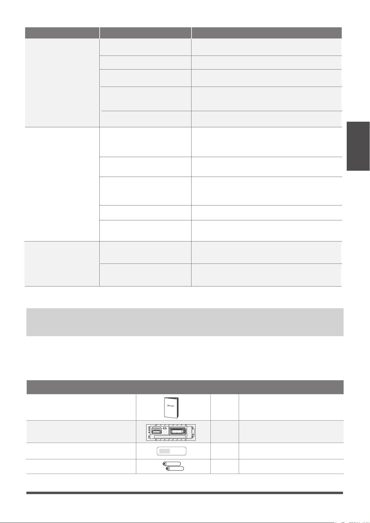
Accessories
The air conditioning system comes with the following accessories. Use all of the installation parts and
accessories to install the air conditioner. Improper installation may result in water leakage, electrical
shock and re, or equipment failure.
Verify that the air conditioner includes the following accessories.
Manual
Name
Installation cardboard template
1
1
1
Shape
Q‘ty(pc)
2
Remote controller
AAA Battery
To purchase
based on
actual project
requirements.
Accessories
Accessories
Note
Connecting pipe
assembly
Name Shape Q‘ty(pc)
Liquid side
Gas side
1/4 in
( Φ 6.35)
3/8in ( Φ 9.52)
1 /2in (
Φ 12.7)
Parts you must purc hase
separately. Consult the dealer
about the proper pipe size of
the unit you purchased.
Page 18
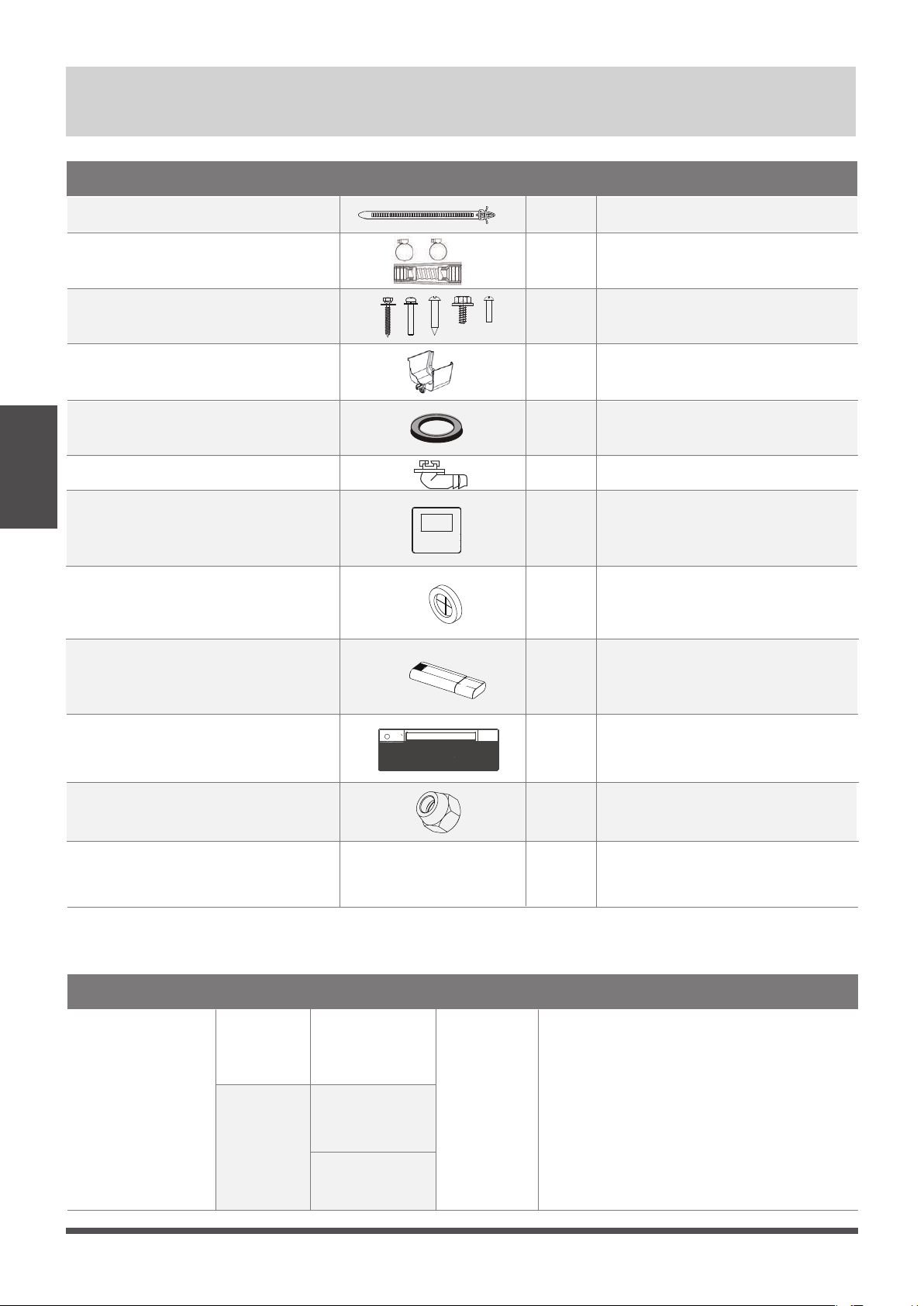
Wire controller (optional)
WiFi controller
(optional)
1
1
1
Panel
1
Name
Water receiver
Cable tie
Drainpipe adaptor
Screw kits (ST8*50 , M4*22 , ST3.9*16
, ST4.8*12,ST3.9*10)
1
6
1
1
(8,8,2,2,3)
Shape
Q‘ty(pc)
Seal
Drain joint
1
1
Rubber ring
Copper nut
2
NOTICENOTICE
Unit Parts
Unit Parts
The installation must be performed in accordance with the requirement of local and national
standards. The installation may be slightly dierent in dierent areas.
NOTE ON ILLUSTRATIONS
Illustrations in this manual are for explanatory purposes. The actual shape of your indoor unit
may be slightly dierent. The actual shape shall prevail.
Page 19
①
②
③
④
⑤
⑥
⑦
⑦
⑧
Disconnect
9
10
Outdoor unit power cable
10
NOTICENOTICE
Indoor Unit
Installation
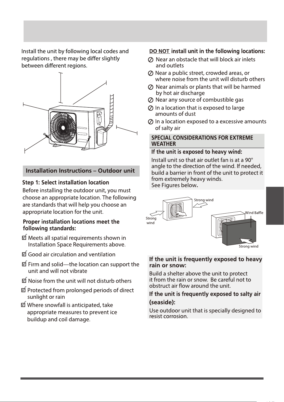
Indoor Unit Installation
Step 1: Select installation location
Before Installation
Before installing the indoor unit, you must
choose an appropriate location. The following
are standards that will help you choose an
appropriate location for the unit.
Enough room exists for installation and
maintenance.
Enough room exists for the connecting the
pipe and drainpipe.
Kitchens that use natural gas
Areas with strong electromagnetic waves
Areas that store ammable materials or gas
Rooms with high humidity, such as
bathrooms or laundry rooms
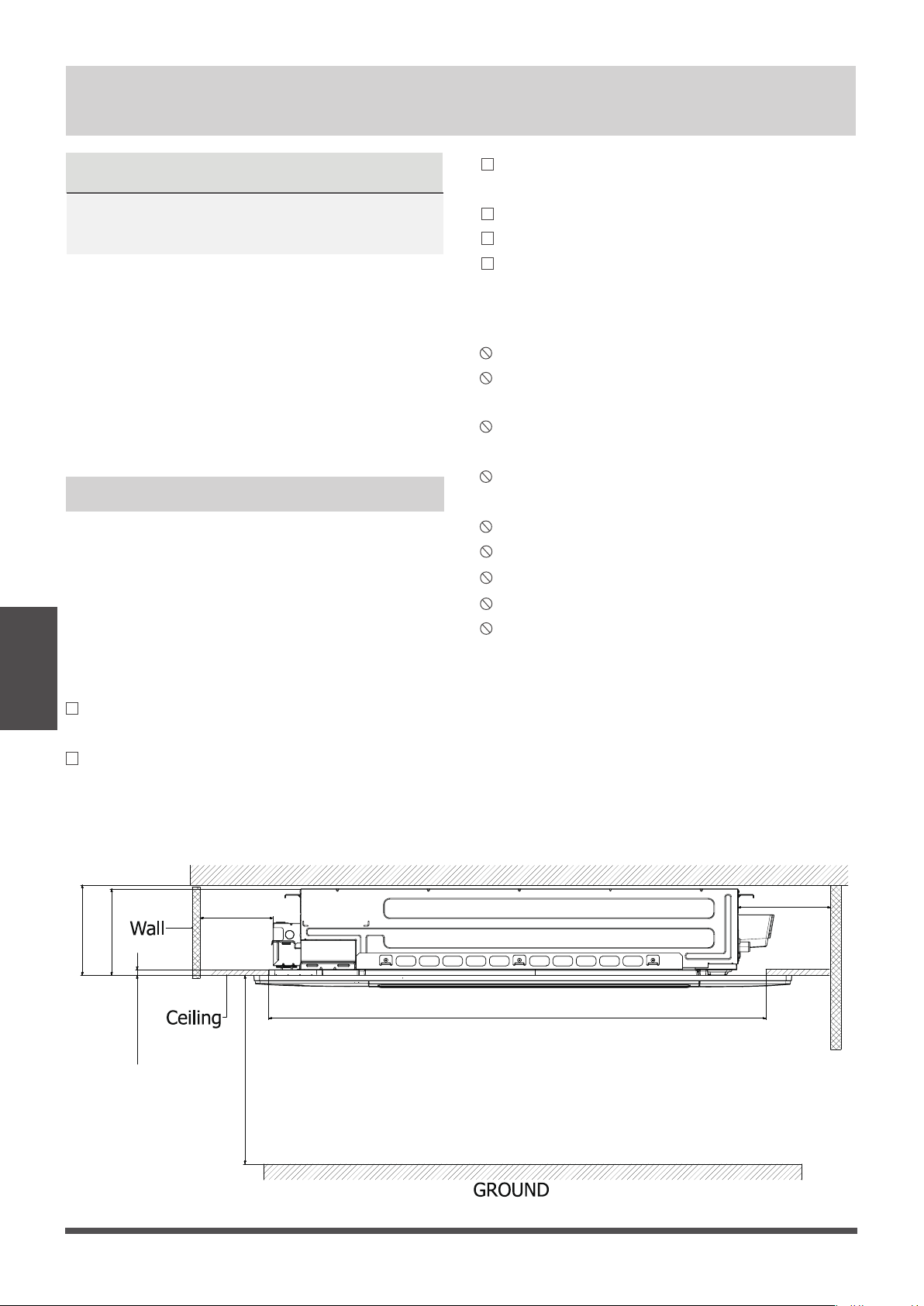
Proper installation locations meet the
following standards:
Panel installation should be performed after
wiring and piping have been completed.
DO NOT install unit in the following
locations:
• Determine the route to move the unit to the
installation site.
• First unseal and unpack the unit. Then, hold
the seats of the hanger (4 pcs) to move the
unit. Refrain from exerting force on other parts
of the unit, especially the refrigerant piping,
water discharge piping, and the plastic parts.
√
√
The ceiling is horizontal and its structure can
sustain the weight of the indoor unit.
The air inlet and outlet are not blocked.
The airow can ll the entire room.
There is no direct radiation from heaters
√
√
√
√
Installation place
Areas with oil drilling or fracking
Coastal areas with high salt content in the
air
Areas with caustic gases in the air, such as
hot springs
Areas that experience power uctuations,
such as factories
Enclosed spaces, such as cabinets
(
unit: inch/mm)
≤5/8 in1( 6mm)
>
19.69 in(500mm)
>8.86 in(225mm)
8.66 in(220mm)
>98.43 in(2500mm)
Ceiling hole
Roof
>
19.69 in(500mm)
Page 20
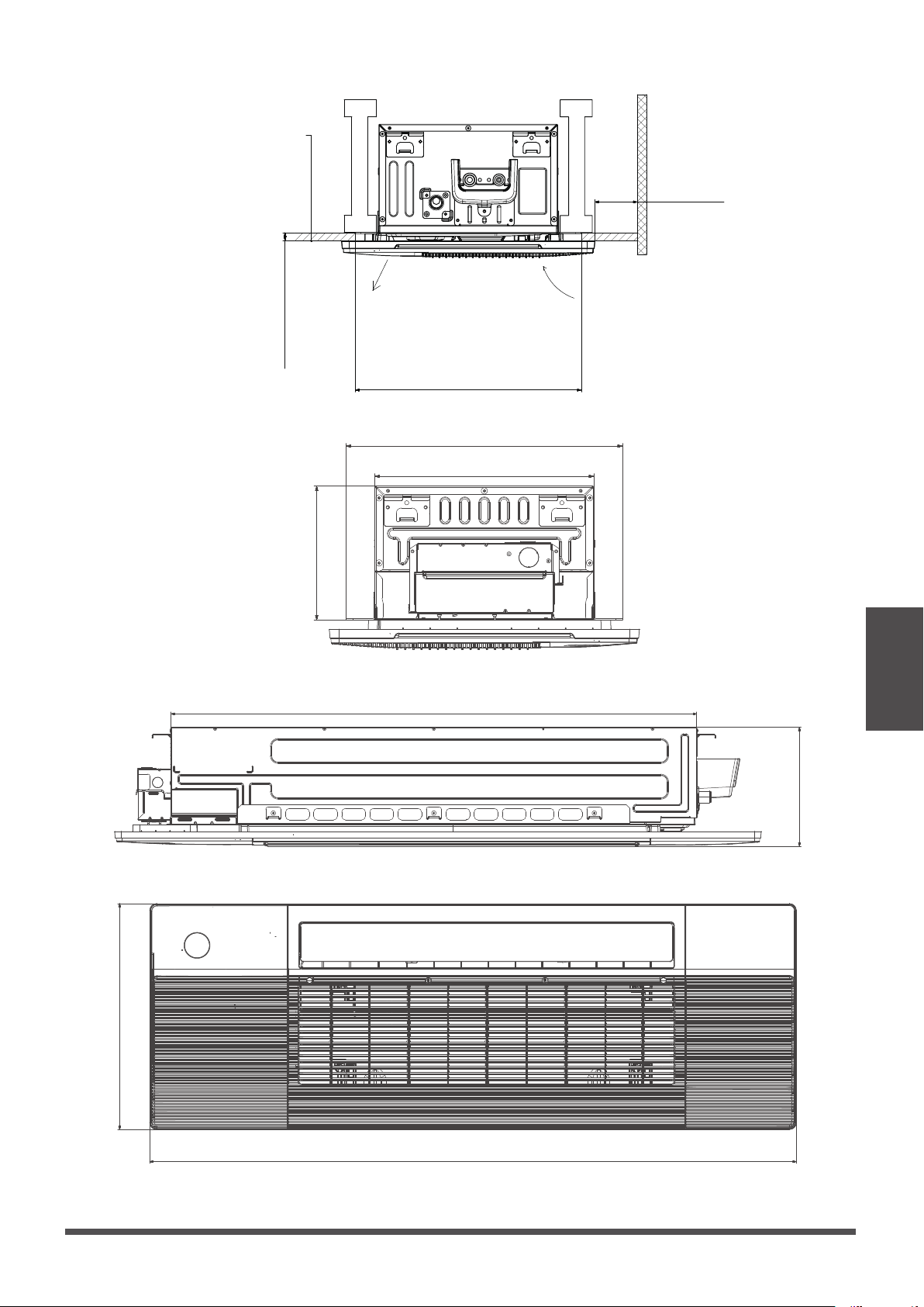
Installation place
(unit: inch/ mm
16.65in (423mm)
13.19in (335mm)
43.5in (1105mm)
9.84in(250mm)
53.54in(1360mm)
18.4in(475mm)
8.07in(205mm)
Indoor Unit
Installation
(unit: inch/mm
Indoor parts installation size
Page 21
≤(5/8 in/16mm)
>7.87 in ( 200mm)
Ceiling hole
air inlet
air outlet
Ceiling
Wall
WARNING
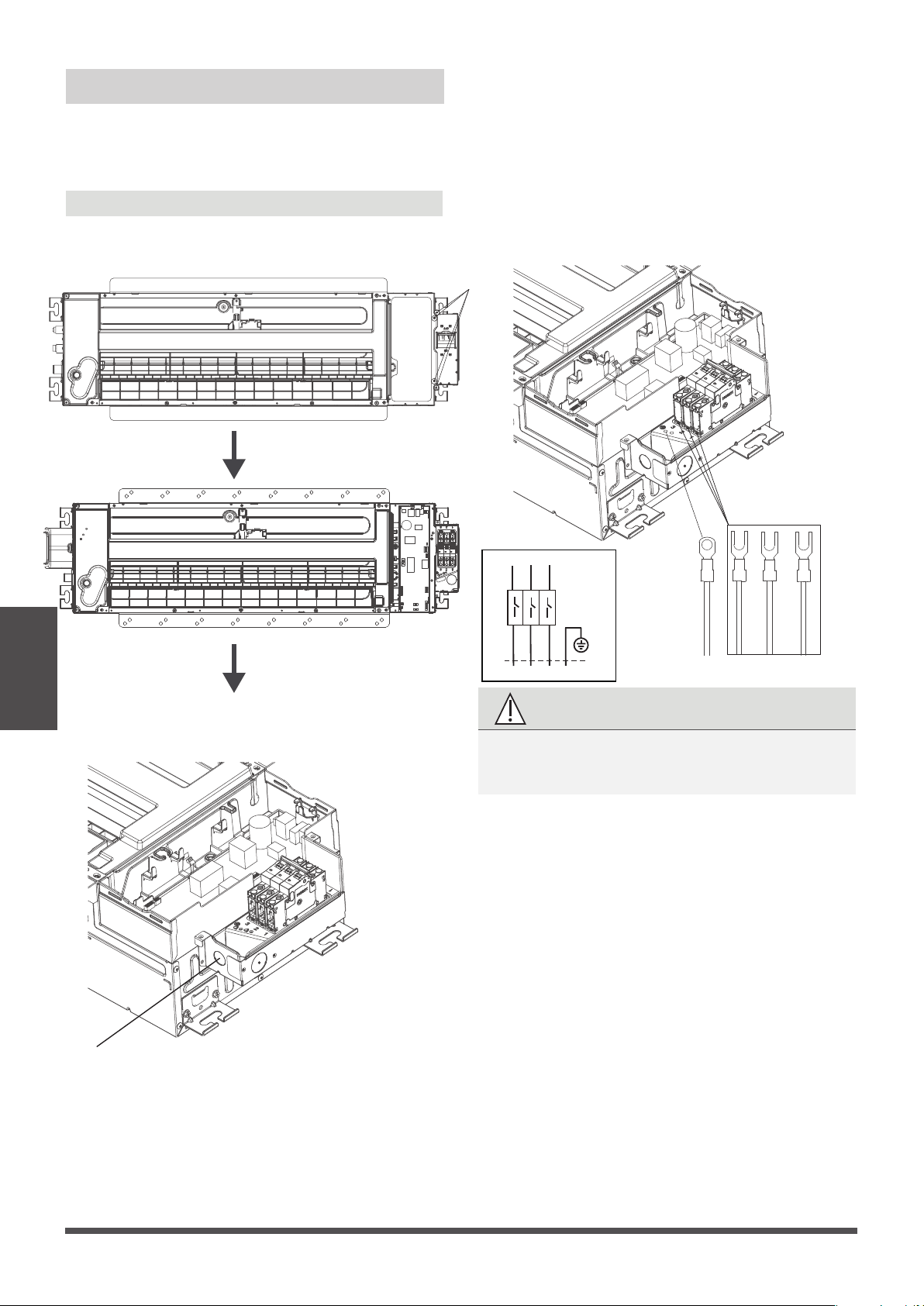
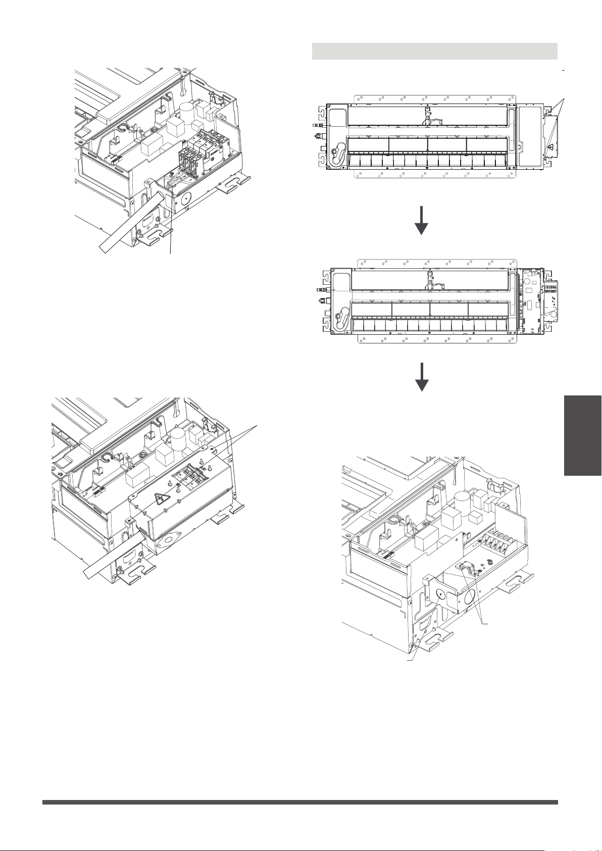
Step 2: Indoor Unit Installation
Make sure that only specied components are
used for the installation works.
1. Connect wire to indoor air handler
●
Remove the four screws to open the indoor
control box and circuit breaker box.
Indoor Unit
Installation
Four screws
● Remove the Knock out cover on the circuit
breaker box.
Knock out cover
●
Connect the wire to the air breaker according
to the wire connecting diagram.
The ground wire should be tighten rmly
without loosening.
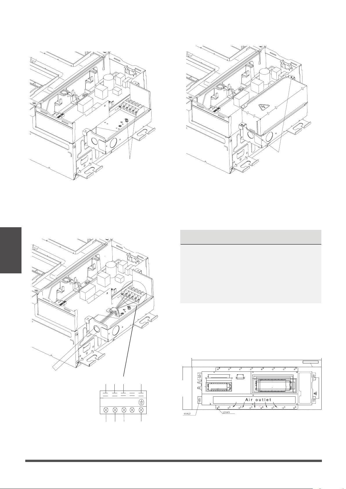
Page 22
3
2
1
TO OUTDOOR UNIT
TO INDOOR UNIT MAIN BOARD
1
2
3
Y/G
Circuit
Breaker
Model A: with circuit breaker
Indoor Unit
Installation
●
Fasten and x the wire body with a tie.
Page 23
Fasten and x the wire body with a tie
●
Install the circuit breaker cover by xing the
two screws.
Two screws
Model B: with terminal
●
Remove the four screws to open the indoor
control box and terminal box.
● Remove the Knock out cover on the terminal box.
Remove the two screws, then take out the clip.
Four screws
Knock out cover
Two screws
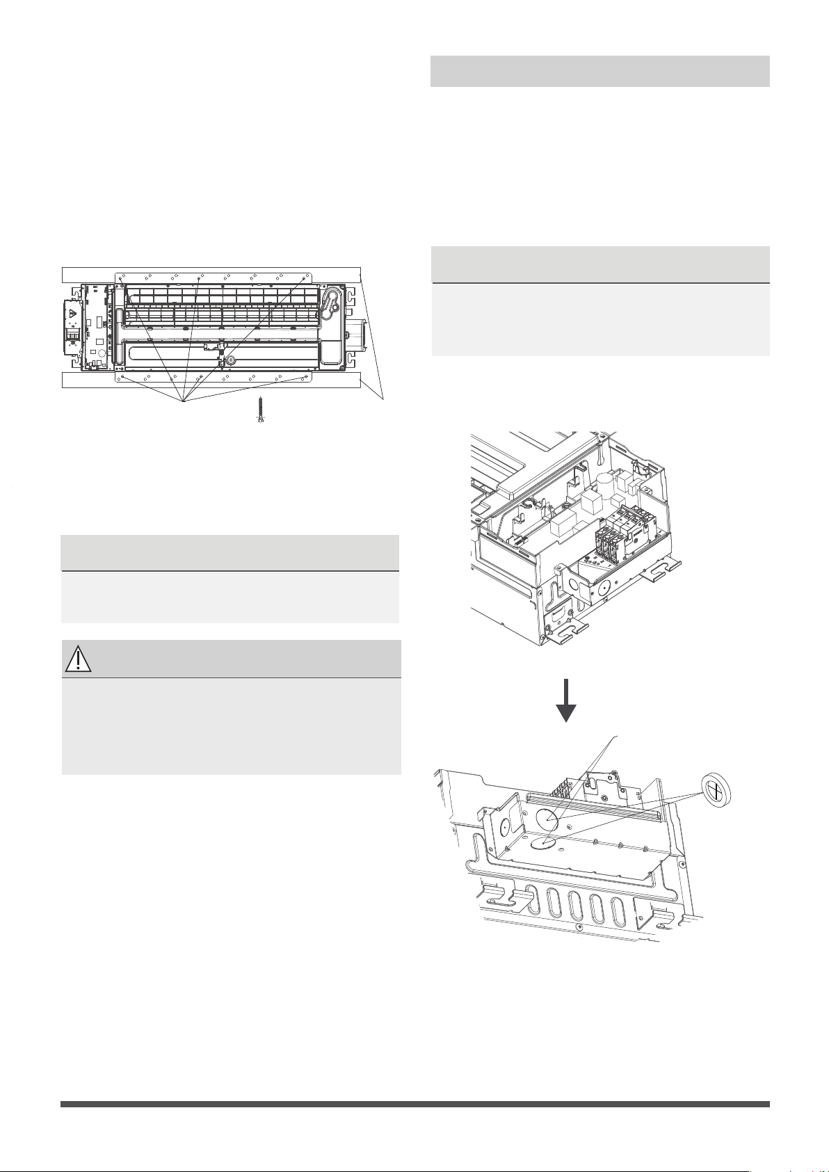
2. Install the indoor air handler
Indoor Unit
Installation
●
After you selecting an installation location, drill
a hole with the diameter of 6mm or less into
the roof beam based on the layout of the
installation board (accessory
Installation
cardboard template
). After drilling the hole,
remove the installation board.
NOTICE
NOTICE
After you have nished installing the main body,
when choosing where to start, determine the
direction of the pipes to be drawn out.
Especially in cases where there is a ceiling involved,
align the refrigerant pipes, drain pipes, and indoor
and outdoor lines with their connection points
before mounting the unit.
Page 24
Installation cardboard template
●
Connect the wire to the terminal according to
the wire connecting diagram.
Select one to
connect ground
wire
●
Fix the wire with the clip by using the two screws.
●
Install the terminal cover by xing the two screws.
Two screws
1
2
3
TO OUTDOOR UNIT
TO INDOOR UNIT MAIN BOARD 16.93’’
(430mm)
51.18’’(1300mm)
CUTTING LINE
NOTICE
The quick-connect installation method is only
used for the models that have been pre-charged
with refrigerant and equipped with quick-connects.
NOTICE
If you choose this conguration, it is
recommended that installing this wire controller
during the step of indoor unit installation.
Wire controller
For the function introduction, operation
instruction and installation, please refer to the
installation and owner’s manual of wire
controller. However, for this machine, please
following the steps for wire connection.
● Remove the specific Knock out cover on the
circuit breaker box.
Knock out cover both
holes can cross the wire,
just select one to install
the rubber ring.
Step 3: Optional parts Installation
●
Align the refrigerant pipes, drain pipeswith their
connection points before mounting the unit.
Mount the indoor unit with at least two people
to lift and secure it then x the unit body to the
roof beam by using 6× ST8.0*50 screws.
Make sure that the screws do not come loose.
Make sure you verify the size and positions of
the opening in the ceiling before you do so.
Roof
beam
Secure with screws
The unit body must be completely aligned
with the hole. Ensure that the unit and the
hole arethe same size before moving on.
Ensure that the indoor unit is horizontal
after installation.
NOTICE
Eight ST8.0*50 screws are supplied, two
of which are spare.
CAUTION
Page 25
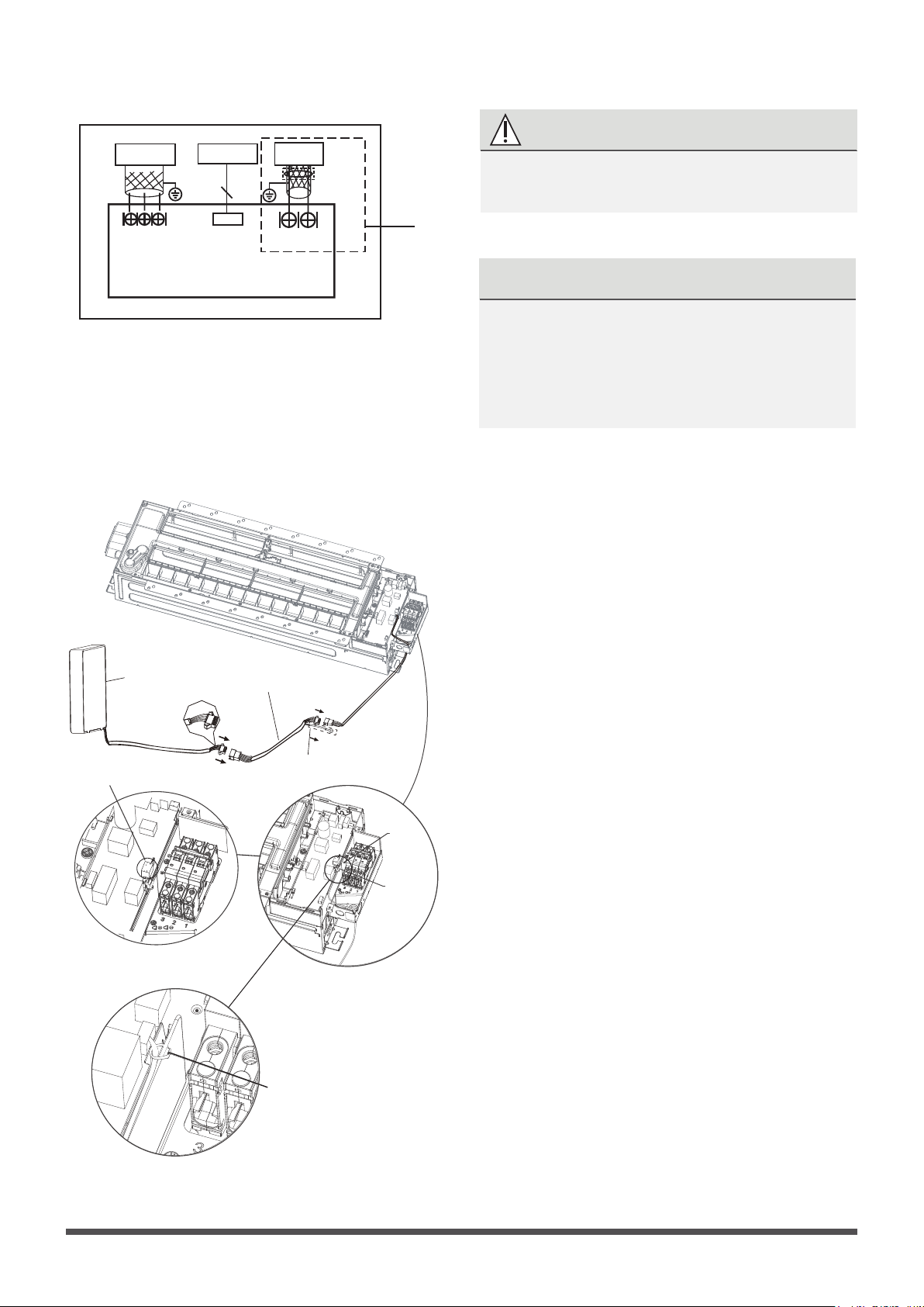
●
Connecting the wire from the control box.
NOTICE
●
Connecting the other side of the connecting
cable to the wire controller.
for ground
wire
CN40
4-core wire
CN41
2-core wire (customer purchases wiring)
Pass a tie through
the hole to x wire .
Wire controller
The connective wires group
shielded wire(some units)
NOTICE
The quick-connect installation method is only
used for the models that have been pre-charged
with refrigerant and equipped with quick-connects.
NOTICE
Be sure to reserve a length of the connecting
wire for periodic maintenance. If there is a
connection lug at the end of shielded wire,
the connection lug should be properly
grounded.
WARNING
I NDOOR UNIT
MAIN BOARD
E
Y X
TO 485 WIRE
CON T ROLLER
CN40
4
To CCM
Comm . Bus
CN41
HB HA
MAGNETIC RING
TO 2 WIRE
Wire-controller
CN3
Please follow local regulations and take
measures to isloate high voltage and low voltage.
CN41 is a
customised
part.
Page 26
outdoor Unit
Installation
Page 27
Outdoor Unit Installation
24in (60cm)
on righ
t
12in (30cm)
on le
in fron
79in (200cm)
t
m back w
12in (30cm)
fro all
24in (60cm) above
outdoor Unit
Installation
Page 28
outdoor Unit
Installation
Page 29
29.9x23.2x11.2in 760x590x285mm 20.85 (530) 11.4 (290)
31.9x22x12.2in 810x558x310mm 21.6 (549) 12.8 (325)
33.27x27.5x12.6 845x700x320mm 22 (560) 13.2 (335)
35.4x33.85x12.4in 900x860x315mm 23.2 (530) 13.1 (333)
37.2x31.9x15.55in 945x810x395mm 25.2 (640) 15.95 (405)
38.98x38x13.58in 990x965x345mm 24.58 (624) 14.4 (344)
37.2x31.9x16.53in 946x810x420mm 26.5 (673)
15.87 (403)
37.2x31.9x16.14in 946x810x410mm 26.5 (673)
15.87 (403)
33.27x27.6x14.3in 845x702x363mm
21.26 (540)
13.8 (350)
15.9 (404)
14.88 (378)
31.5x21.8x13.1in 800x554x333mm 20.24 (514) 13.39 (340)
36.93x53.9x15.43in 938x1369x392mm 24.96 (634)
35.4x46x13.8in 900x1170x350mm 23.2 (590)
37.5x52.5x16.14in 952x1333x410mm 24.96 (634)
15.9 (404)
37.5x52.5x16.14in 952x1333x415mm 24.96 (634)
15.9 (404)
(unit: in/mm)
30.1x21.8x11.9in 765x555x303mm
17.8
(452)
11.3
(286)
35.0x 26.5x 13.5in 890x673x342mm
26.1 (663)
13.9 (354)
31.7x21.8x1.9in 31.7x21.8x12.9 20.1 (511) 12.5 (317)
30.3x21.8x11.8in 770x555x300mm
19.2 (487)
11.7 (298)
9.8"/25cm or more
11.8"/30cm or more
9.8"/25cm
or more
9.8"/25cm
or more
118"/300cm or more
23.6"/60cm
or more
59"/150cm
or more
outdoor Unit
Installation
Page 30
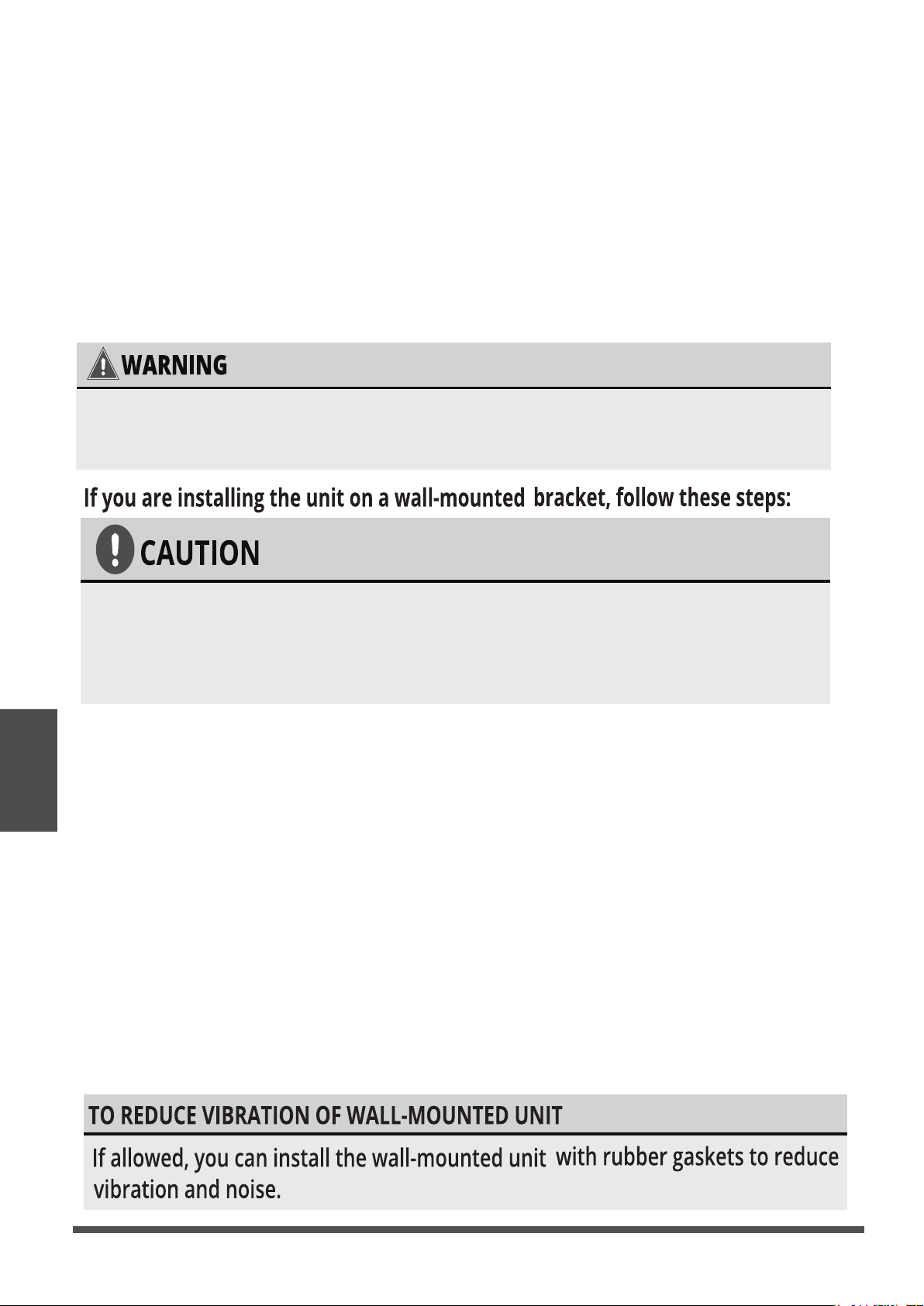
Before installing a wall-mounted unit,make sure that the wall is made of
solid brick, concrete,or a similarly strong material. The wall must be able
to support at least 4 times the weight of the unit.
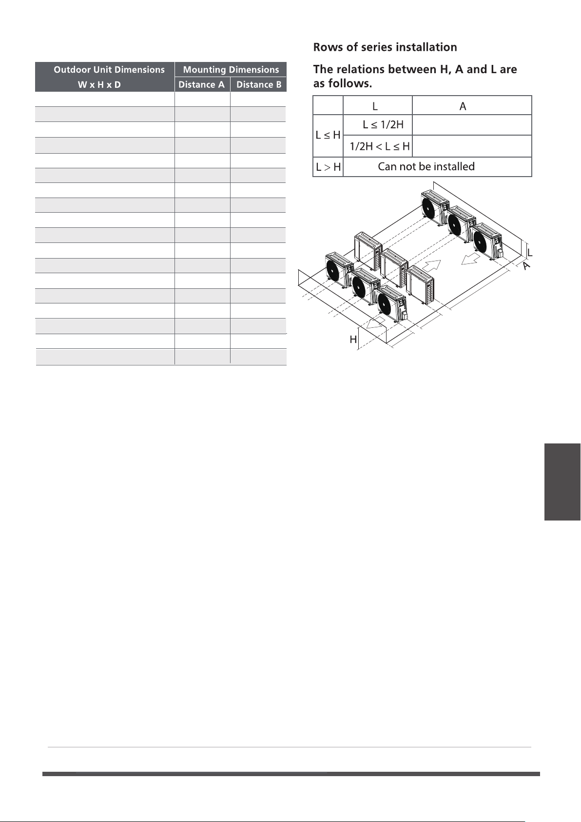
1.Mark the position of the bracket holes based on the dimensions in the Mounting Dimensions
chart on the previous page.
2.Pro-drill the holes for the expansion bolts.
3.Clean dust and debris away from the holes.
4.Place a washer and nut on the end of each expansion bolt.
5.Thread expansion bolts through the holes in the mounting brackets.Then,put the mounting
brackets in position and hammer the expansion bolts into the wall.
6. Check that the mounting brackets are level.
7.If the feet of the outdoor unit have rubber pads already installed , and you are using a local
dealer s wall-mounting bracket,remove them before attempting to mount the condenser to
the bracket.The mounting bracket has rubber isolating pads on it that will take the place of
these.
8.Carefully lift the unit and place its mounting feet on the brackets.
9.Then,bolt the unit rmly to the brackets.
,
If you are installing the outdoor unit on the ground,or a concrete mounting
platform,use the following steps:
1.Mark the positions for four expansion bolts based on dimensions in the Mounting Dimensions
chart and illustrations above.
2.Pre-drill holes for expansion bolts.
3.Clean concrete dust away from the holes.
4.Place a nut on the end of each expansion bolt.
5.Hammer expansion bolts into the pre-drilled holes.
6.Remove the nuts from the expansion bolts,and place outdoor unit on bolts.
7.Put a washer on each of the expansion bolts,then reinstall the nuts.
8.Using a wrench,tighten each nut until snug.
WHEN DRILLING INTO CONCRETE,EYEPROTECTION
IS RECOMMENDED AT ALL TIMES.
Drainpipe Installation
Drainpipe
Installation
Page 31
The drainpipe is used to drain water away from
the unit. Improper installation may cause unit
and property damage.
•
Insulate all piping to prevent condensation,
which could lead to water damage.
• If the drainpipe is bent or installed
incorrectly, water may leak and cause a
water-level switch malfunction.
•
In HEAT mode, the outdoor unit will
discharge water. Ensure that the drain hose
is placed in an appropriate area to avoid
water damage and slippage.
• DO NOT pull the drainpipe forcefully. This
could disconnect it.
NOTE ON PURCHASING PIPES
Installation requires a PVC tube (exterior
diameter = 1in (25mm ) (depending on
models ), which can be obtained at your
localhardware store or dealer.
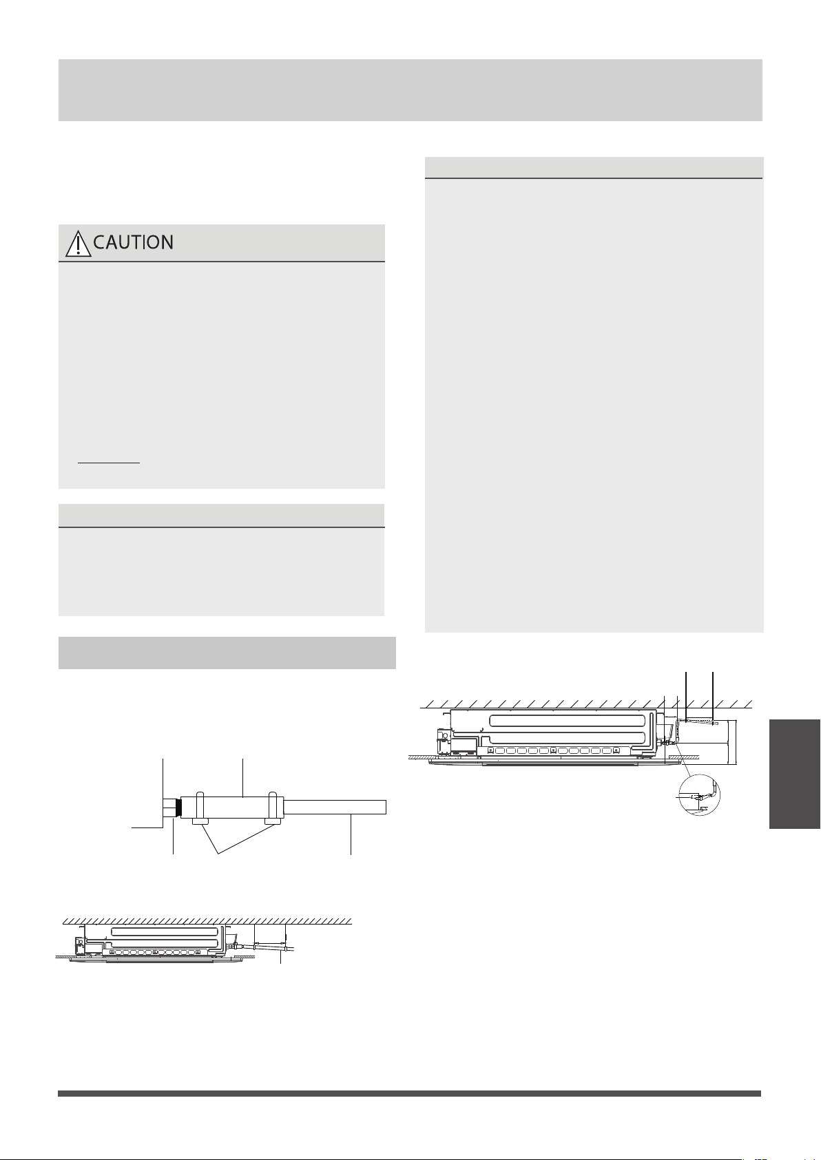
Indoor Drainpipe Installation
Install the drainpipe as illustrated in the following
Figure.
Connect drainpipe to the indoor unit via drain
adaptor.
Drainpipe
connecting port
Drainpipe
Drain adaptor
Metal clamp
Downward slope
1/100
39-59”
(1-1.5m
)
NOTE ON DRAINPIPE INSTALLATION
•
When using an extended drainpipe, tighten
the indoor connection with an additional
protection tube to prevent it from pulling
loose.
• The drainpipe should slope downward at a
gradient of at least 1/100 to prevent water
from owing back into the air conditioner.
•
To prevent the pipe from sagging, space
hanging wires every 39-59” (1-1.5m).
If the outlet of the drainpipe is higher than
the body’s pump joint, provide a lift pipe for
the exhaust outlet of the indoor unit. The
lift pipe must be installed no higher than
29.5” (75cm) from the ceiling board and the
distance between the unit and the lift pipe
must be less than 11.8” (30cm) (depending
on models ).
Incorrect installation could cause water to
flow back into the unit and flood.
To prevent air bubbles, keep the drain hose
level or slightly tiled up (< 3”/75m )
(some models ).
•
•
≤29.5”
(
75cm)
39-59”
(1 - 1.5m)
3”
(
75mm)
≤
11.8”
(30cm)
≤
20.8”
(
53cm)
8.6”
(22cm)
NOTICENOTICE
Drainpipe
Installation
Page 32
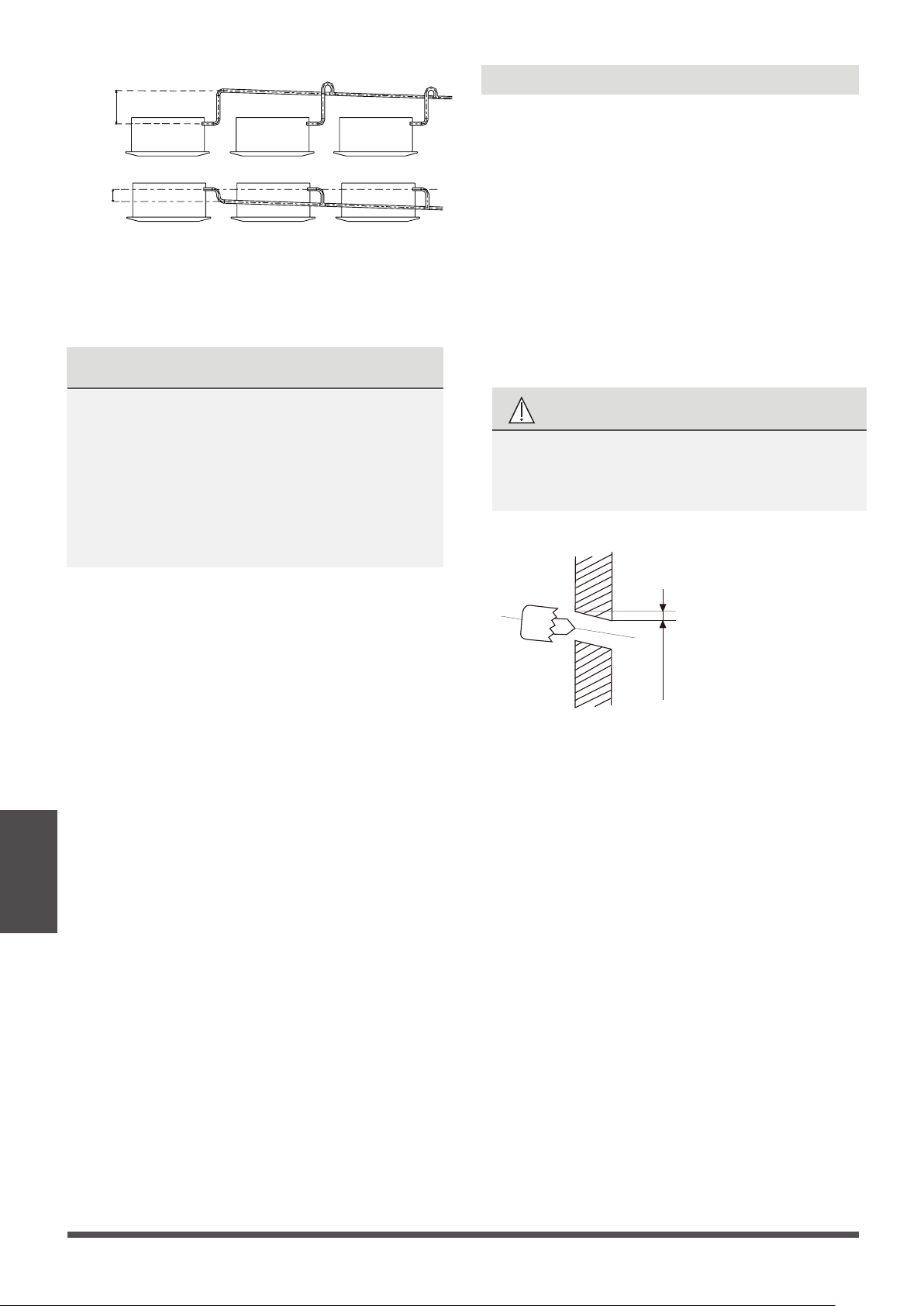
Pass the drain hose through the wall hole.
Make sure the water drains to a safe location
where it will not cause water damage or a
slipping hazard.
The drainpipe outlet should be at least
1.9” (5cm) above the ground. If it touches the
ground, the unit may become blocked and
malfunction. If you discharge the water directly
into a sewer, make sure that the drain has a U
or S pipe to catch odors that might otherwise
come back into the house.
20.8”
(0-53cm
)
≥
4”
(10cm
)
Wall
Indoor Outdoor
0.2-0.275in
(5-7mm)
Fig.3.2
1. Using a 2.5in (65mm) or 3.54in(90mm)
(depending on models )core drill, drill a hole
in the wall. Make sure that the hole
is drilled at a slight downward angle, so
that the outdoor end of the hole is lower than
the indoor end by about 0.2-0.275in (5mm to
7mm). This will ensure proper water drainage.
2. Place the protective wall cuff in the hole. This
protects the edges of the hole and will help
seal it when you finish the installation process.
CAUTION
When drilling the wall hole, make sure to
avoid wires, plumbing, and other sensitive
components.
Drill wall hole
Φ
NOTE: When the gas side connective pipe is
5/8in(16mm) or more, the wall hole should be
3.54in (90mm).
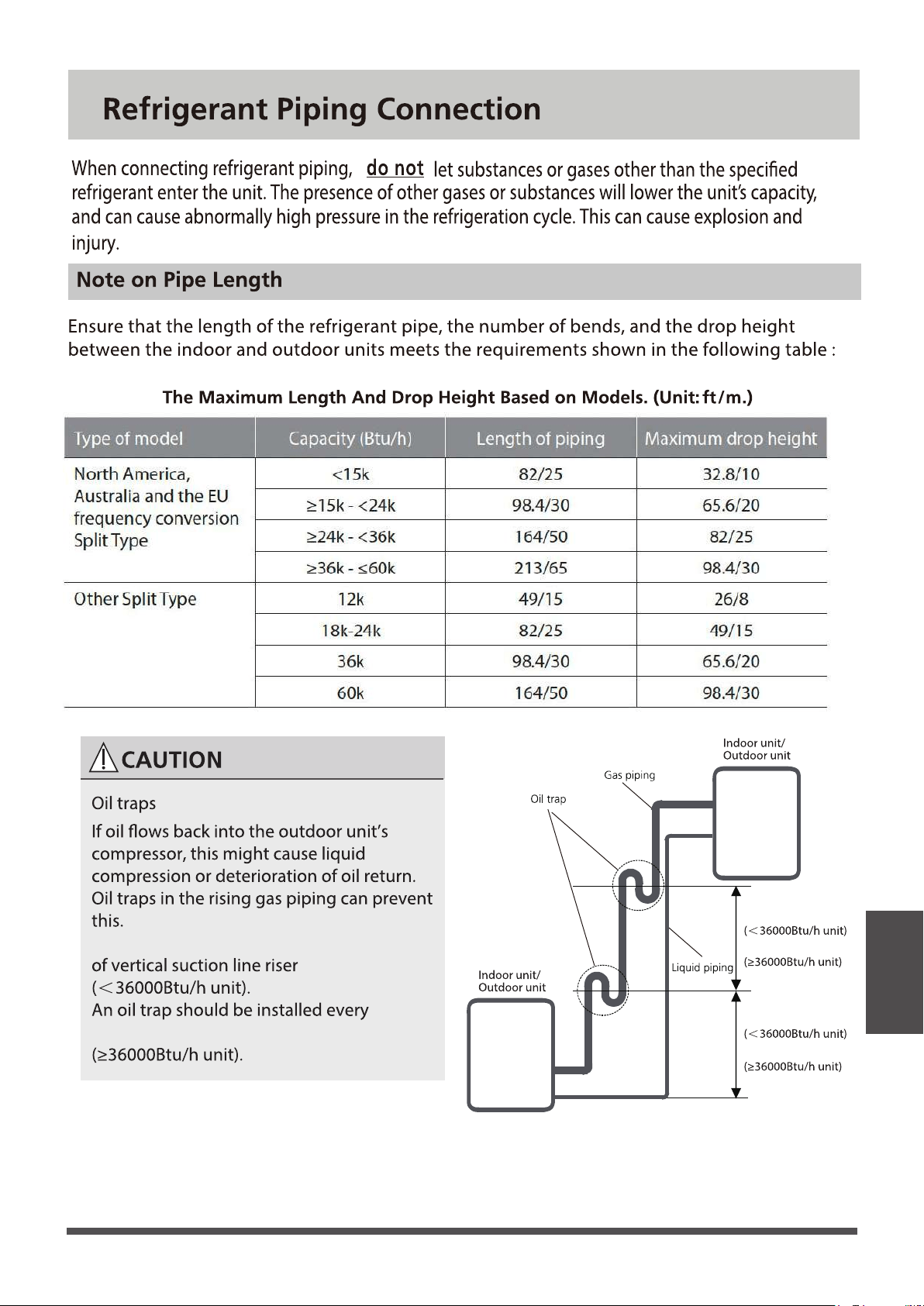
Refrigerant
piping
Connection
Page 33
20ft/6m
32.8ft/10m
20ft/6m
32.8ft/10m
An Oil trap should be installed every 20ft/6m
32.8ft/10m of vertical suction line riser
Refrigerant
piping
Connection
Page 34
Refrigerant
piping
Connection
Page 35
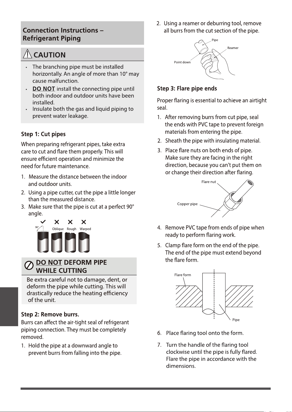
7.Thread this pipeline through the wall and connect
it to the outdoor unit.
8.Insulate all the piping , including the valves of the
outdoor unit.
9.Fix the water receiver (supplied in Accessories box)
to the indoor unit by a screw.
10.Open the stop valves of the outdoor unit to start
the ow of the refrigerant between the indoor and
outdoor unit.
NOTICE
Two ST4.8*12
screws are supplied,
one of which
is spare.
6.After connecting the copper pipes to the indoor
unit,wrap the power cable , signal cable and the
piping together with binding tape.
ST4.8*12 screw
Refrigerant
piping
Connection
Page 36
Electrical Connections
11. If the unit has an auxiliary electric heater, it must be installed at least 40 in (1 meter)
away from any combustible materials.

Refrigerant
piping
Connection
Page 37
(Some indoor unit come
with their own)
(Some indoor unit come
with their own)
(Some indoor unit come
with their own)
Disconnect switch
Disconnect switch
Disconnect switch
Disconnect switch
Page 38
Refrigerant
piping
Connection
18
7 - 10
16
11 - 15 14
16 - 20 12
21 - 30 10
31 - 40
8
3 - 6
49 - 55
6
to reveal approximatly 5.9" (15cm) of
Page 39
about 5.9"(15cm) of the wire
Refrigerant
piping
Connection
Page 40
Run the vacum to 500 microns or less
Refrigerant
piping
Connection
Φ
1/2in(12.7 )
R410A:
(orice tube in the indoor unit):
Page 41
Refrigerant
(Total pipe length-
standara pipe length)
×0.32oz(30g)/ft(m)
(Total pipe length-
standara pipe length)
×0.69oz(65g)/ft(m)
(Total pipe length-
standara pipe length)
×1.23oz(115g)/ft(m)
(Total pipe length-
standara pipe length)
×0.16oz(15g)/ft(m)
(Total pipe length-
standara pipe length)
×0.32oz(30g)/ft(m)
(Total pipe length-
standara pipe length)
×0.69oz(65g)/ft(m)
R410A:
(orice tube in the outdoor unit):
Φ 3/8in( 9.52)
Φ 1/4in( 6.35)
Liquid Side Diameter
d pipe length is 25' ( 7.5m)
pipe connections points DO NOT leak, replace
the valve cover on the outside unit and wrap
and insulate the piping connections of the
indoor unit.
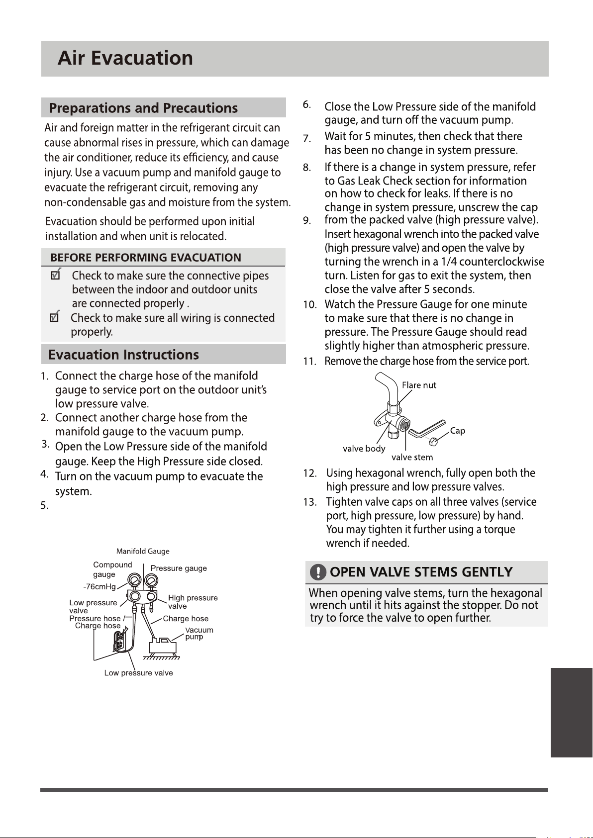
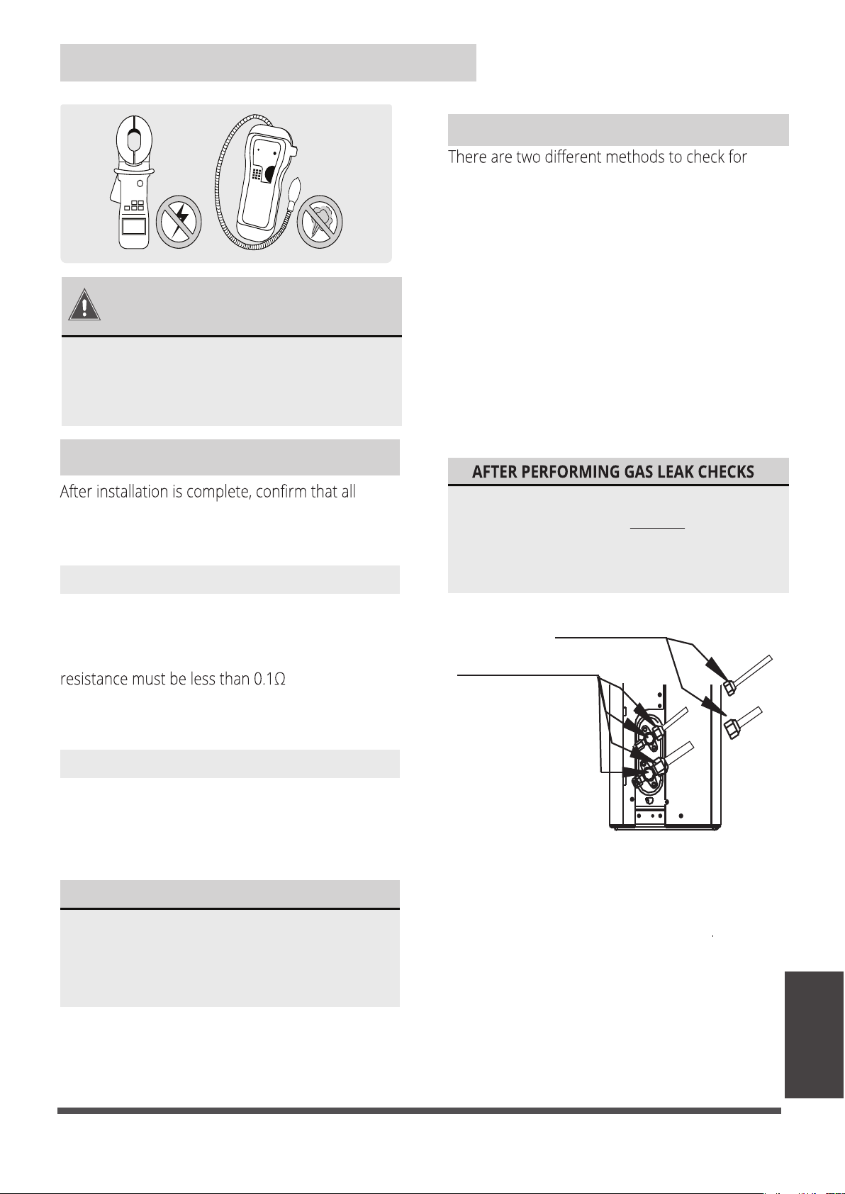
BEFORE TEST RUN
Using a soft brush or spray bottle, apply a soapy
water solution to all of the pipe connection points of
the indoor and outdoor units, watching to see if any
bubbles form. The presence of bubbles indicates
there is a leak.
gaseous leaks. Use Fig. 8.1 below as a guide for
the critical points to check for leaks.
Soap and Water Method
Leak Detector Method
If using a leak detector, refer to the device’s
operation/instruction manual for proper usage
instructions.
Gas Leak Checks
IF ELECTRICAL LEAKAGE IS DETECTED
unit immediately and call a licensed
If electrical leakage is detected, turn o the
the leakage.
electrical wiring has been installed in accordance
with local and national regulations, and according
to the installation manual.
Check Grounding Work
Measure grounding resistance by visual detection
and with a grounding resistance tester. Grounding
.
NOTE: This may not be required for some
locations in North America.
Check for Electrical Leakage
During the Test Run, use an electroprobe and
multimeter to perform a comprehensive electrical
leakage test.
NOTE: This may not be required for some
locations in North America.
Electrical Safety Checks
DURING TEST RUN
WARNING – RISK OF
ELECTRICAL SHOCK
ALL WIRING MUST BE INSTALLED BY A
LOCAL, STATE, AND NATIONAL ELECTRICAL
CODES.
Check-point of indoor unit
Check-point of outdoor unit
A
B
C
D
Fig. 8.1
Electrical and
Gas Leak Checks
Electrical and Gas leak Checks
A: Low pressure stop valve
B: High pressure stop valve
C & D: Indoor unit are nuts
electrician to nd and resolve the cause of
LICENSED ELECTRICIAN AND COMPLY WITH
After confirming that all of the refrigerant
Page 42
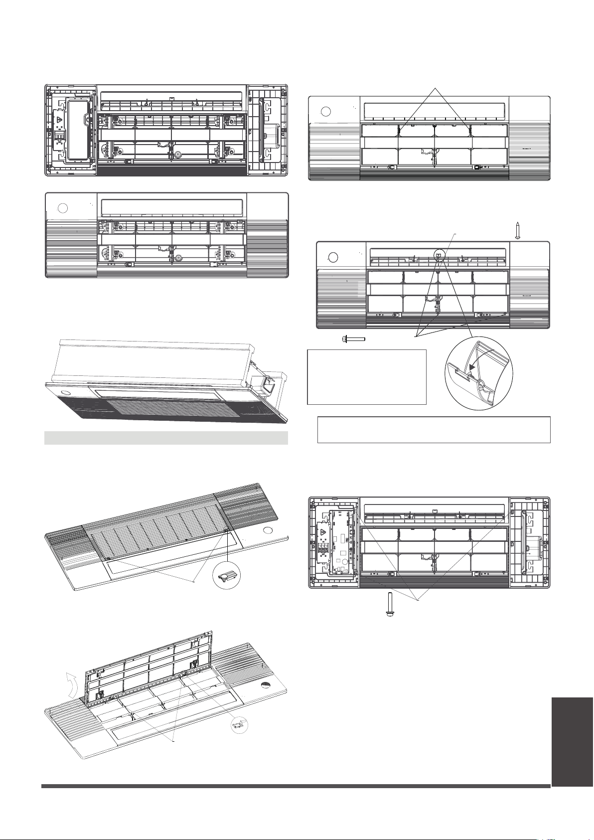
Panel Installation
●
Pull the panel grille out of the panel, x the
cassette panel to the one-way cassett by two
plastic buckles.
●
Grab air grille with your ngers and pull it out
slowly in the direction of the arrow.
NOTICENOTICE
The corresponding colors or corresponding
pins are connected each other.
when connection is completed, please clip
the wires to the buckle.
●
Manually rotate the air deector, x the panel
to the cassette by using 3×M4*22 screws and a
ST3.9*16 screw.
Before xing this screw, you need to open the screw cover;
and after xing screw, please close the cover.
Panel Installation
Step1 Prepare and install ceiling
●
Connect the display board to the main control
board, up to four wires are required to connect.
●
Open the two covers on both sides of the panel ,
x the panel to the cassette by using 3× M4*22
screws.
M4*22 screw
(white 10-core)
(white 5-core)
(red 5-core)
( 4 core)
NOTICE
Eight M4*22 screws are
supplied, two of which are
spare. Two ST3.9*16 screws
are supplied, one of which is spare.
Step 2 Panel Installation
● Drill 16.93’’x51.18’’( 430 mm x 1300 mm ) hole
into the ceiling based on the layout of the
installation board.
The centre of the ceiling opening should
match the centre of the body of the indoor
unit.
NOTICE
In order to keep the ceiling level and prevent
vibrations, reinforce the strength of the ceiling
when necessary.
● Once the ceiling is cut, remove the installation
board.
● then install the ceiling.
●
The air grille received by the customer is not
tightened by the wire rope,but is specially
designed to be loose for easy installation.
NOTICE
Model A
Grab at these locations
M4*22 screw
ST3.9*16 screw
Page 43
●
Install the control box cover and turn the
circuit breaker to ON, then close the two plastic
covers on both sides of the panel.
●
During the test-run process, the display
wil be lighted and the air griller will rise
automatically.
Panel Installation
Model B
●
Press the circular positon to open the two
screw covers, then remove the two screws.
Screw Covers
●
Hold and open the air grille, then push both
of the latch to the middle to unlock the air grille.
Before xing this screw, you need to open the screw cover;
and after xing screw, please close the cover.
●
Open the two covers on both sides of the panel ,
x the panel to the cassette by using 3× M4*22
screws.
M4*22 screw
NOTICE
Eight M4*22 screws are
supplied, two of which are
spare. Two ST3.9*16 screws
are supplied, one of which is spare.
M4*22 screw
ST3.9*16 screw
●
Pull the panel grille out of the panel, x the
cassette panel to the one-way cassett by two
plastic buckles.
●
Manually rotate the air deector, x the panel
to the cassette by using 3×M4*22 screws and a
ST3.9*16 screw.
palstic buckle
Latch
Page 44
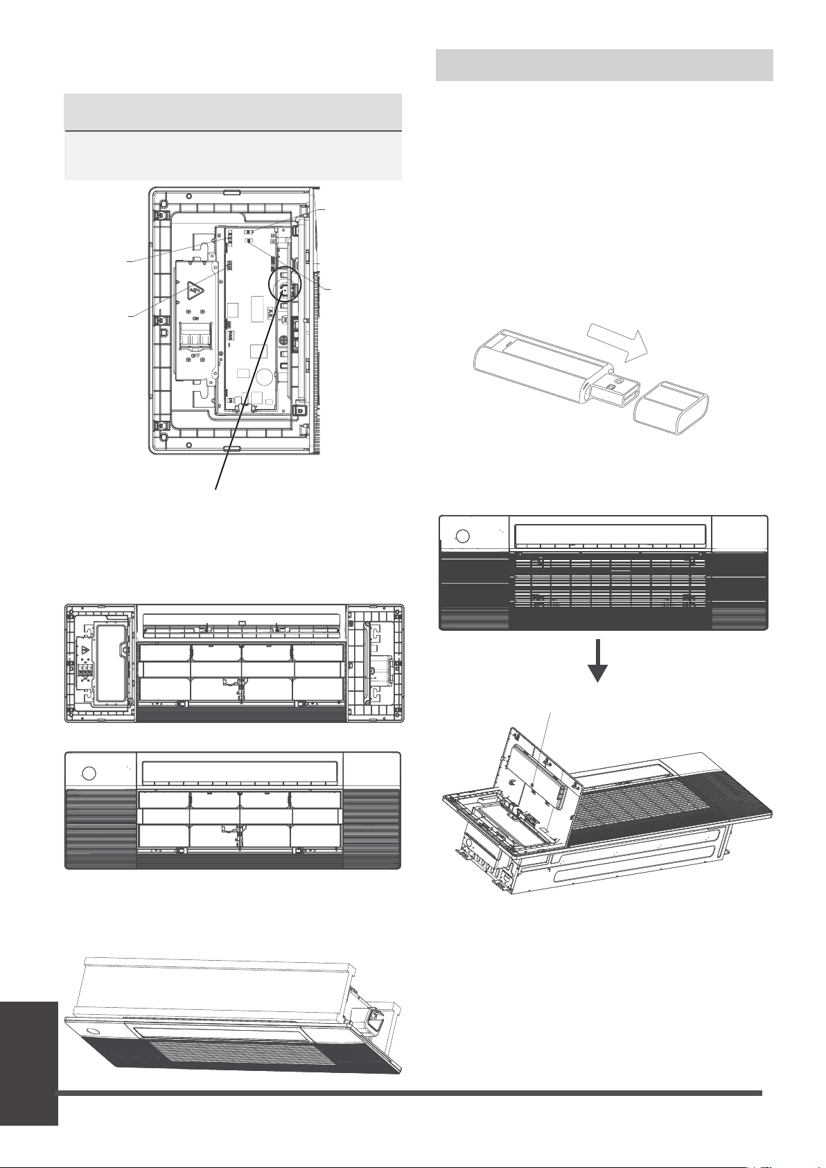
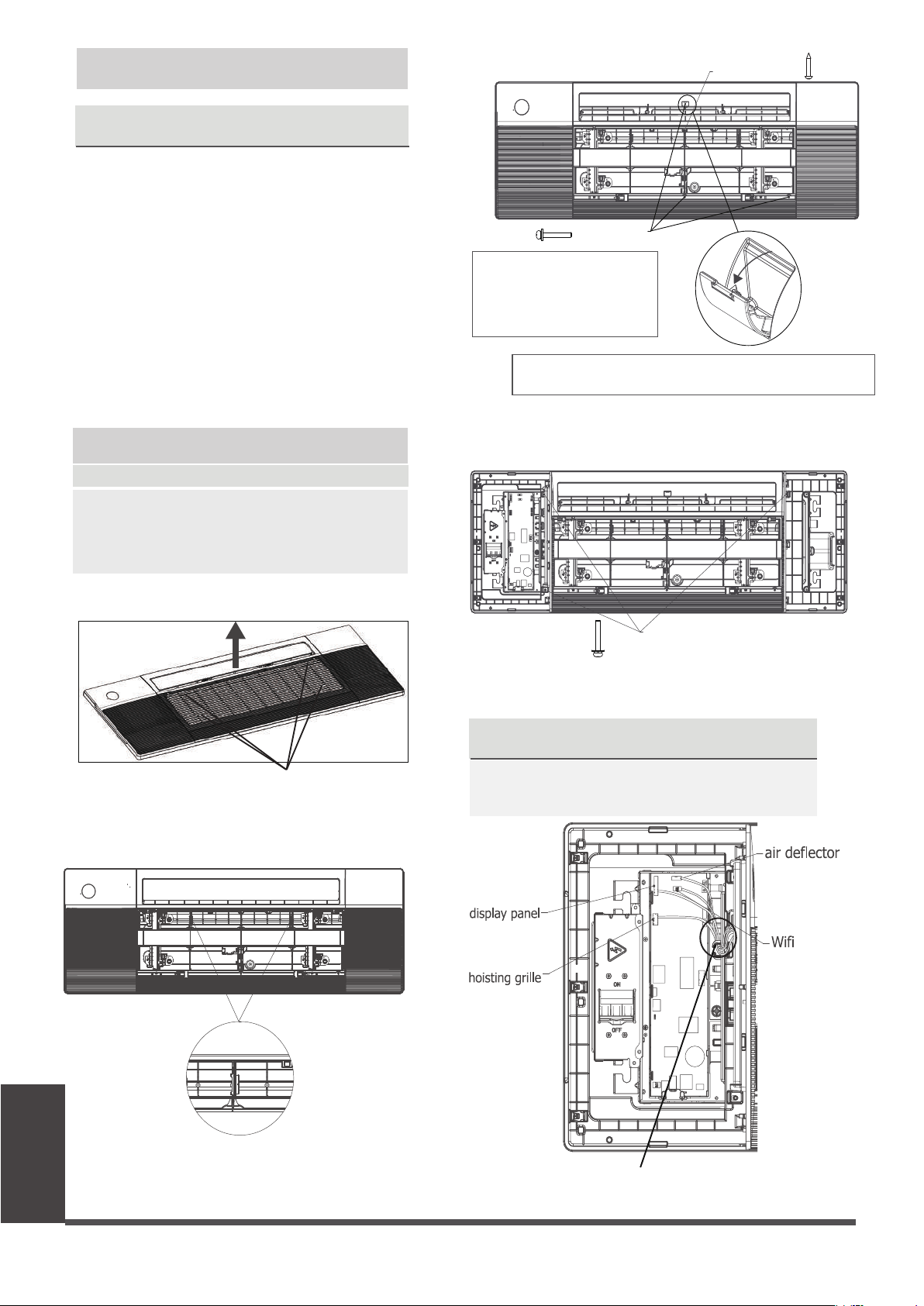
●
Open the cover with display panel, loosen the
screw and remove the cover.
Loosen the screw and remove the cover
NOTICE
If you choose this conguration, it is
recommended that installing this wireless
module during the step of panel installation.
Wireless module
Wireless module, or named smart kit, if you
choose this conguration, please follow the
steps below to install.
●
Remove the protective cap of the wireless
module (smart kit).
Step 3 Optinal parts installation
Test Run
NOTICENOTICE
The corresponding colors or corresponding
pins are connected each other.
●
Connect the display board to the main control
board, up to four wires are required to connect.
display panel
(white 10-core)
air deector
(white 5-core)
hoisting grille
(red 5-core)
Wi
(4 core)
when connection is completed, please clip
the wires to the buckle.
●
Install the control box cover and turn the
circuit breaker to ON, then close the two plastic
covers on both sides of the panel.
●
Re-install the air grille by pushing the latchto
lock it and xing the two screws, then close the
two screw covers.
Page 45

Test Run
●
Open the front panel and insert the wireless
module (smart kit) into the reserved interface.
WARNING
• This interface is only compatible with
wireless module (smart kit) provided by
the manufacturer.
For the function introduction and operation
instruction, please refer to the user manual of
Smart kit.
infraed controller plug
5 core
CAUTION
Failure to perform the test run may result in
unit damage, property damage, or personal
injury.
Test Run Instructions
1. Open both the liquid and gas stop valves.
2. Turn on the main power switch and allow the
unit to warm up.
3. Set the air conditioner to COOL mode.
4. For the Indoor Unit
a.
b.
c.
Double check to see if the room
temperature is being registered correctly.
d.
Ensure the manual buttons on the indoor
unit works properly.
Check to see that the drainage system is
unimpeded and draining smoothly.
Ensure there is no vibration or abnormal
noise during operation.
5. For the Outdoor Unit
a. Check to see if the refrigeration system is
leaking.
b. Make sure there is no vibration or
abnormal noise during operation.
c. Ensure the wind, noise, and water
generated by the unit do not disturb your
neighbors or pose a safety hazard.
NOTE: If the unit malfunctions or does not
operate according to your expectations,
please refer to the Troubleshooting section
of the Owner’s Manual before calling
customer service.
Before Test Run
A test run must be performed after the entire
system has been completely installed. Confirm
the following points before performing the test:
a) Indoor and outdoor units are properly
installed.
b) Piping and wiring are properly connected.
c)
No obstacles near the inlet and outlet of
the unit that might cause poor performance
or product malfunction.
d) Refrigeration system does not leak.
e) Drainage system is unimpeded and
draining to a safe location.
f) Heating insulation is properly installed.
g) Grounding wires are properly connected.
h) Length of the piping and additional
refrigerant stow capacity have been
recorded.
i) Power voltage is the correct voltage
for the air conditioner.
Page 46
The drainage plug at the bottom of the unit body is used to discharge accumulated water from
the drain pan when the air conditioner malfunctions. When the air conditioner is operating
normally, make sure the drainage plug is properly plugged to prevent water from leaking.
• Before the test, make sure that the water discharge pipeline is smooth, and check that each
connection is sealed properly.
• Conduct the water discharge test in the new room before the ceiling is paved.
1. Connect the power supply, and set the air conditioner to operate in the cool mode.
Check the running sound of the drainage pump.
2. keep cool mode running at least 10 min.
3. Stop the air conditioner. Wait for three minutes, and then check if there is anything
unusual. If the water discharge piping layout is not correct, the excessive water ow will
cause the water level error and “EE” error code will be displayed on the display panel. There
may even be water overowing from the water pan.
4. Continue to add water until the alarm for excessive water levels is triggered. Check if the
drainage pump drains water immediately. After three minutes, if the water level does not
fall below the warning level, the unit will shut down.
At this time, you need to turn o the power supply, and drain away the accumulated water
before you can turn on the unit normally.
5. Turn o the power supply, remove the water manually using the drainage plug, and put
the test cap back to the original place.
Water Discharge Test
Page 47
LIMITED WARRANTY STATEMENT
MULTI ZONE INVERTER AIR CONDITIONING SYSTEM WITH HEAT PUMP
This warranty should be registered on our website www.cooperandhunter.us within 60 days of installation
The warranty is only valid when unit is installed by a Licensed HVAC Technician
FOR WARRANTY SERVICE OR REPAIR:
Contact your installing contractor. You may nd the installer’s name on the equipment or in your Owner’s packet.
Complete product registration below and send back by e-mail at warranty@cooperandhunter.us
C&H distributor (hereinafter “Company”) warrants this product against failure due to defect in materials or
workmanship under normal use and maintenance as follows. All warranty periods begin on the date of original
installation. If the date cannot be veried, the warranty period begins one hundred twenty (120) days from date of
manufacture. Damage resulting from failure to use, install or maintain the product in a manner consistent with our/
manufacturer’s recommendations shall render the warranty void. Cooper&Hunter, at its option, may request a report
from a qualied technician prior to honoring a warranty claim. If a part fails due to defect during the applicable
warranty period Company will provide a new or remanufactured part, at Company’s option, to replace the failed
defective part at no charge for the part. This limited warranty is subject to all provisions, conditions, limitations and
exclusions listed below.
•
A warranty period of Seven (7) years on compressor to the original registered end-user.
• A warranty period of Five (5) years on all parts to the original registered end user.
• A warranty period of One (1) year on the remote control provided with the original unit.
PRODUCT REGISTRATION:
Model No.: ______________________________________________________________________________________________
Serial No.: _______________________________________________________ Date of Installation: ______________________
Owner Name: ____________________________________________________________________________________________
Address of Installation:_____________________________________________________________________________________
Installing Contractor: __________________________________________________________________________
____________
Address: ________________________________________________________________________________________
Phone No. / E-mail: _______________________________________________________________________________
Place Of Purchase:
________________________________________________________________________________________
Date of Purchase:
_______________________________________________________________________________
www.cooperandhunter.us
Visit our website for:
• Product Information
• Warranty Registration
• Installation Manual
• User Guides and more
www.cooperandhunter.us
Visit our YouTube Channel for:
• Instructional Videos
• Tutorials and How Tos
• Product Introductions
• Advertisement and more
www.youtube.com/
cooperandhunterusa

The design and specications are subject to change without prior notice for
product improvement. Consult with the sales agency or manufacturer for
details. Any updates to the manual will be uploaded to the service website,
please check for the latest version.

• Limited warranty applies only to systems that are properly installed by a state certied or licensed HVAC contractor,
under applicable local and state law in accordance with all applicable building codes and permits; C&H installation and
operation instructions and good trade practices.
• Warranty applies only to products remaining in their original installation location.
• Defective parts must be returned to the distributor through a registered servicing dealer for credit.
LIMITATIONS OF WARRANTIES: ALL IMPLIED WARRANTIES AND/OR CONDITIONS (INCLUDING IMPLIED WARRANTIES OR
CONDITIONS OF MERCHANTABILITY AND FITNESS FOR A PARTICULAR USE OR PURPOSE) ARE LIMITED TO THE DURATION
OF THIS LIMITED WARRANTY. SOME STATES OR PROVINCES DO NOT ALLOW LIMITATIONS ON HOW LONG AN IMPLIED
WARRANTY OR CONDITION LASTS, SO THE ABOVE MAY NOT APPLY TO YOU. THE EXPRESS WARRANTIES MADE IN THIS
WARRANTY ARE EXCLUSIVE AND MAY NOT BE ALTERED, ENLARGED, OR CHANGED BY ANY DISTRIBUTOR, DEALER, OR
OTHER PERSON, WHATSOEVER.
THIS WARRANTY DOES NOT COVER:
1. Labor or other costs incurred for diagnosing, repairing, removing, installing, shipping, servicing, or handling of
defective parts, replacement parts, or new units.
2. Product cleaning required prior to warranty service and repair.
3. Normal maintenance as outlined in the installation and servicing instructions or user’s manual, including lter cleaning
and/or replacement and lubrication.
4. Failure, damage, or repairs due to faulty installation, misapplication, abuse, improper servicing, unauthorized
alteration,
or improper operation.
5. Failure to start due to voltage conditions, blown fuses, open circuit breakers, or damages due to the inadequacy or
interruption of electrical service.
6. Failure or damage due to oods, winds, res, lightning, accidents, corrosive environments (rust, etc.), or other
conditions beyond the control of Company.
7. Failure or damage of coils or piping due to corrosion on installations within one (1) mile of a sea coast or a corrosive
body.
8. Parts not supplied or designated by Company, or damages resulting from their use.
9. Products installed outside the continental USA and Canada.
10. Electricity or fuel costs, or increases in electricity or fuel costs for any reason whatsoever, including additional or
unusual use of supplemental electric heat.
11. Any cost to replace, rell, or dispose of refrigerant, including the cost of refrigerant.
12. Shipping damage or damage as a result of transporting the unit.
13. Accessories such as condensate pumps, line sets, and so forth.
14. Any special, indirect, or consequential property or commercial damage of any nature whatsoever. Some states or
provinces do not allow the exclusion of incidental or consequential damages, so the above limitation may not apply to
you.
This warranty gives you specic legal rights, and you may also have other rights which vary from state to state or province
to province.
Design and specications are subject to change without prior notice for product improvement.
Consult with the sales agency or manufacturer for details.