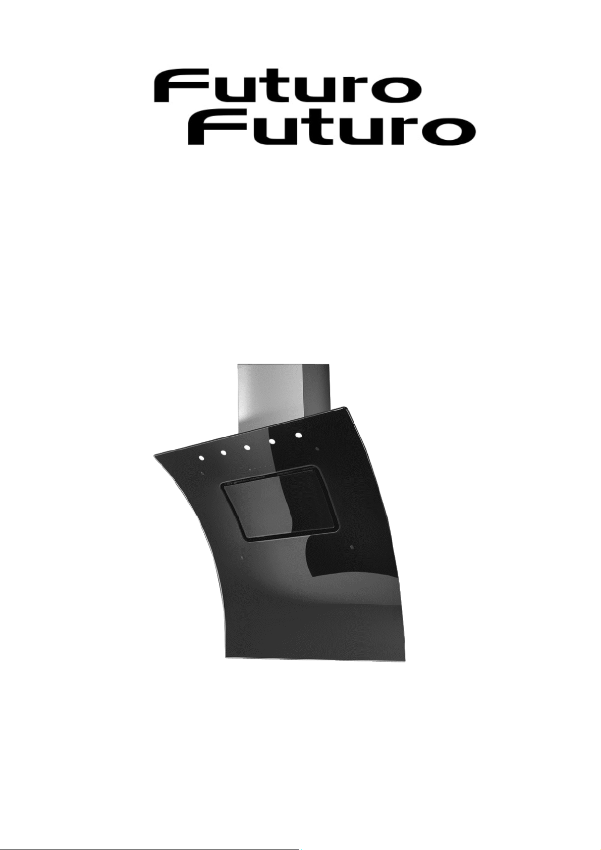
36 SPLASH WALL
INSTALLATION, OPERATING AND MAINTENANCE GUIDE

2
I GENERAL ........................................................................................................... 3
II WARNINGS ......................................................................................................... 3
III INSTALLATION .................................................................................................... 4
III.1 Preliminary Indications .................................................................................... 4
III.2 Fixing the wood to the wall ............................................................................... 5
III.3 Electrical Connection ...................................................................................... 5
IV USE ................................................................................................................ 5
V OPERATION ........................................................................................................ 6
V.I Hood control .................................................................................................. 6
V.2 Adjustable and delayed self-switching off .............................................................. 6
V.3 Maintenance reminder ..................................................................................... 6
V.4 24h Comfort function ....................................................................................... 6
VI MAINTENANCE AND CLEANING ................................................................................. 7
VI.1 Metal grease filter .......................................................................................... 7
VI.2 Activated carbon filters (for filtering hoods) .......................................................... 7
VI.3 Hood Cleaning ............................................................................................... 7
VI.4 Lighting ...................................................................................................... 7
VII DISCONTINUATION .............................................................................................. 7
120V – 60HZ

3
I GENERAL
Installation, operating and maintenance instructions for cooker hood model 36 SPLASH WALL.
120V – 60HZ
READ AND SAVE THESE INSTRUCTIONS
II WARNINGS
CAUTION: Automatically Operated Device – To Reduce The Risk Of Injury
Disconnect From Power Supply Before Servicing.
WARNING: To Reduce The Risk Of Fire Or Electric Shock, Do Not Use This Fan With Any Solid-State Speed Control
Device.
PAY ATTENTION TO:
A) THE NEED FOR FREQUENT CLEANING OF ALL GREASE FROM THE FAN AND FROM ALL OTHER GREASE-LADEN
SURFACES;
B) THE NEED FOR FREQUENT REMOVAL AND CLEANING OF ANY FILTER UNIT PROVIDED.
WARNING: To provide protection against electric shock, connect to properly grounded outlets only.
For Residential Use Only
WARNING: GROUNDING INSTRUCTIONS
This appliance must be grounded. In the event of an electrical short circuit, grounding reduces the risk of electric
shock by providing an escape wire for the electric current. This appliance is equipped with a cord having a
grounding wire with a grounding plug. The plug must be plugged into an outlet that is properly installed and
grounded.
WARNING – Improper grounding can result in a risk of electric shock.
Consult a qualified electrician if the grounding instructions are not completely understood, or if doubt exists as to
whether the appliance is properly grounded. Do not use an extension cord. If the power supply cord is too short,
have a qualified electrician install an outlet near the appliance.
WARNING – TO REDUCE THE RISK OF FIRE, USE ONLY METAL DUCTWORK.
WARNING – TO REDUCE THE RISK OF A RANGE TOP GREASE FIRE:
a) Never leave surface units unattended at high settings. Boilovers cause smoking and greasy spillovers that may
ignite. Heat oils slowly on low or medium settings.
b) Always turn hood ON when cooking at high heat or when flambeing food (i.e. Crepes Suzette, Cherries Jubilee,
Peppercorn Beef Flambe’).
c) Clean ventilating fans frequently. Grease should not be allowed to accumulate on fan or filter.
d) Use proper pan size. Always use cookware appropriate for the size of the surface element.
WARNING – TO REDUCE THE RISK OF INJURY TO PERSONS IN THE EVENT OF A RANGE TOP GREASE FIRE, OBSERVE
THE FOLLOWING:
a) SMOTHER FLAMES with a close-fitting lid, cookie sheet, or metal tray, then turn off the burner.
BE CAREFUL TO PREVENT BURNS. If the flames do not go out immediately,
EVACUATE AND CALL THE FIRE DEPARTMENT.
b) NEVER PICK UP A FLAMING PAN – You may be burned.
c) DO NOT USE WATER, including wet dishcloths or towels – a violent steam explosion will result.
d) Use an extinguisher ONLY if:
1) You know you have a Class ABC extinguisher, and you already know how to operate it.
2) The fire is small and contained in the area where it started.
3) The fire department is being called.
4) You can fight the fire with your back to an exit.
THE MINIMUM DISTANCE BETWEEN THE SUPPORTING SURFACE OF THE COOKING HOB AND THE LOWEST PART OF
THE RANGE HOOD MUST BE NOT LESS THAN 26IN (65 CM) WITH A GAS HOB.
4
READ AND SAVE THESE INSTRUCTIONS
Keep these instructions in a safe place and pass them on to any future user. Read these instructions carefully before
installing or using the range hood.
Before connecting the appliance to the power supply make sure that the voltage (V) and frequency (Hz) listed on the
data plate correspond with the household electrical supply. This data must correspond to prevent appliance damage.
Installation work and repairs should only be performed by a qualified technician under all applicable codes and standards.
Repairs and other work by unqualified persons could be dangerous.
In the event of a fault, please contact the Technical Service authorized to provide genuine parts. When contacting the
Technical Service, please quote the model and the serial number of your appliance. These are shown on the data plate.
Ensure that power to the appliance is OFF while the appliance is not in use.
During thunderstorms switch-off the main switch of the house electrical system or if the device is equipped with a plug,
simply unplug it.
Use this appliance only in the manner intended by the manufacturer and no other than exhausting cooking fumes on
domestic kitchens.
The manufacturer does not accept any liability for damages caused by people, animals, or things, by installation and
maintenance mistakes, or by any illegitimate use.
Observe the following essential safety instructions during the use of any electrical appliance:
•This appliance is not intended for use by persons (including children) with reduced physical, sensory or mental
capabilities, or lack of experience and knowledge unless they have been given supervision or instruction concerning the
use of the appliance by a person responsible for their safety. Children should be supervised to ensure that they do not
play with the appliance.
•To prevent the risk of fire it is compulsory to disconnect the appliance from the power supply before cleaning or
servicing the hood;
•Do not pull, take off, or twist the cable coming out from the appliance, even though this has been disconnected from
the main power supply.
•Do not sprinkle or throw any water directly on the appliance.
•Do not stick any sharp tool inside the exhausting holes and into the air outlet.
•Do not take out the filters to reach the internal sides of the appliance in case the main switch of the house electrical
system is not off.
•Do not flambé or grill with an open flame beneath the hood. Flames could be drawn up into the hood by the suction
and the filters may ignite.
•Pay particular attention while frying. Heat oils slowly on low or medium settings.
•CAUTION: Accessible parts may become hot when used with cooking appliances.
•It is forbidden to use the hood as a support surface unless it is expressly indicated.
•Only use the fixing screws supplied with the product for installation.
III INSTALLATION
III.1 Preliminary Indications
Carefully read the guide before installation and use of the appliances.
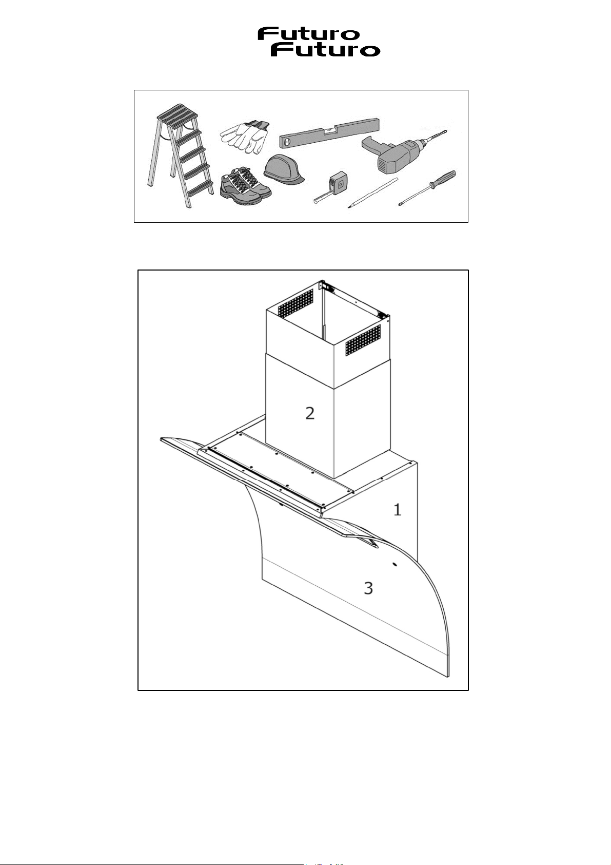
The installation requires safety equipment and a range of tools as per Fig. 3.1.1.
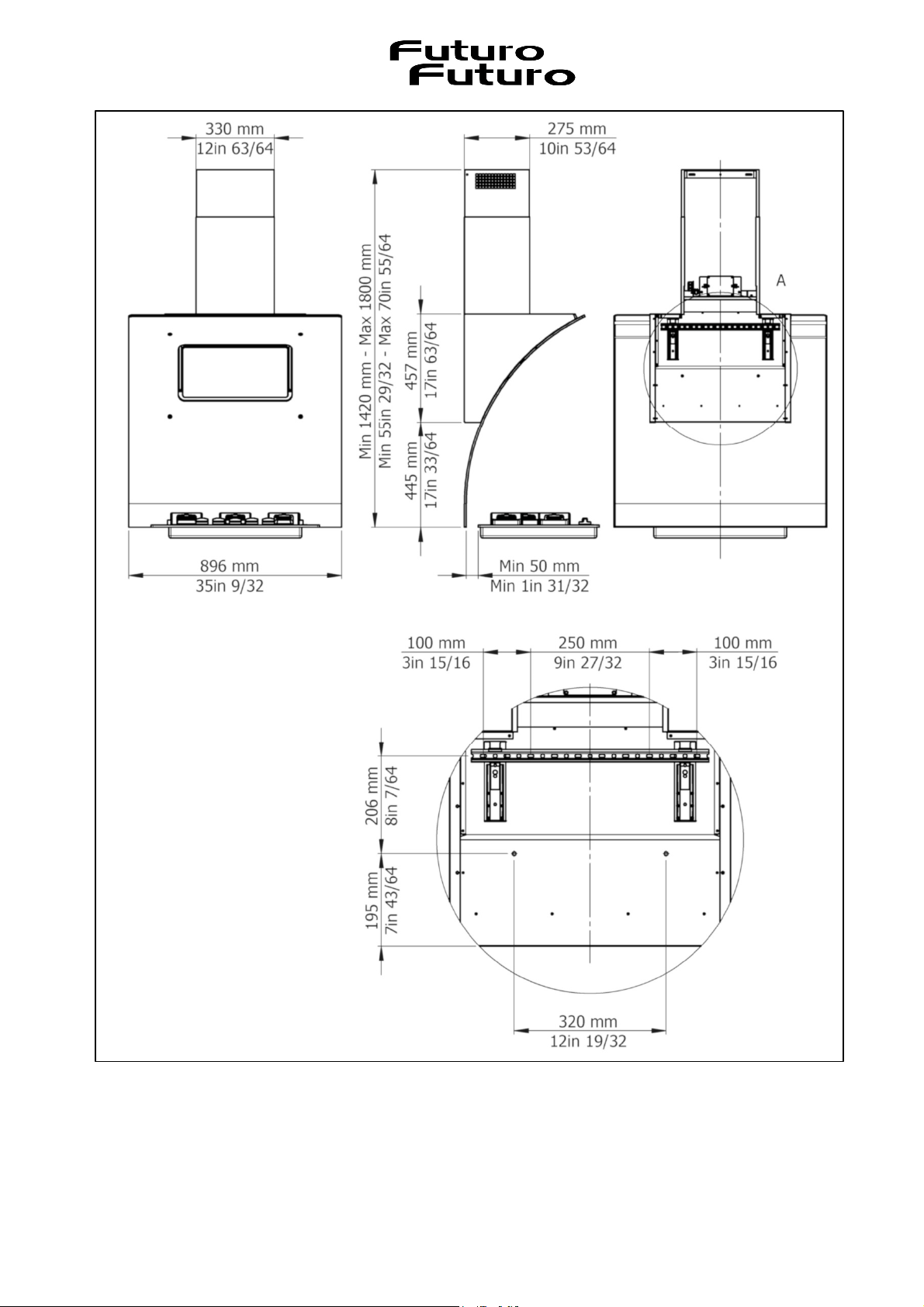
With the hood correctly installed, the minimum distance between the supporting surface of the cooking hob and the
lowest part of the range hood must be not less than 26in for both electric and gas cooktops.
If the mounting instructions of the gas hob indicate a wider distance, respect it.
It must not be superimposed on stoves with an upper radiating plate.
Respect all the air discharge regulations.
The air must not be discharged in a pipe used to discharge exhaust fumes produced by gas-fed equipment or fuel-fed
equipment.
The room must be adequately ventilated when the hood is used together with other gas or fuel types of equipment.
The hood is equipped with all the necessary fastenings for its installation, which are suitable for most surfaces.
Verify that the installation surface is strong.
Installation must be carried out by qualified installers according to present regulations.
CAUTION: Accessible parts may become hot when used with cooking appliances.
5
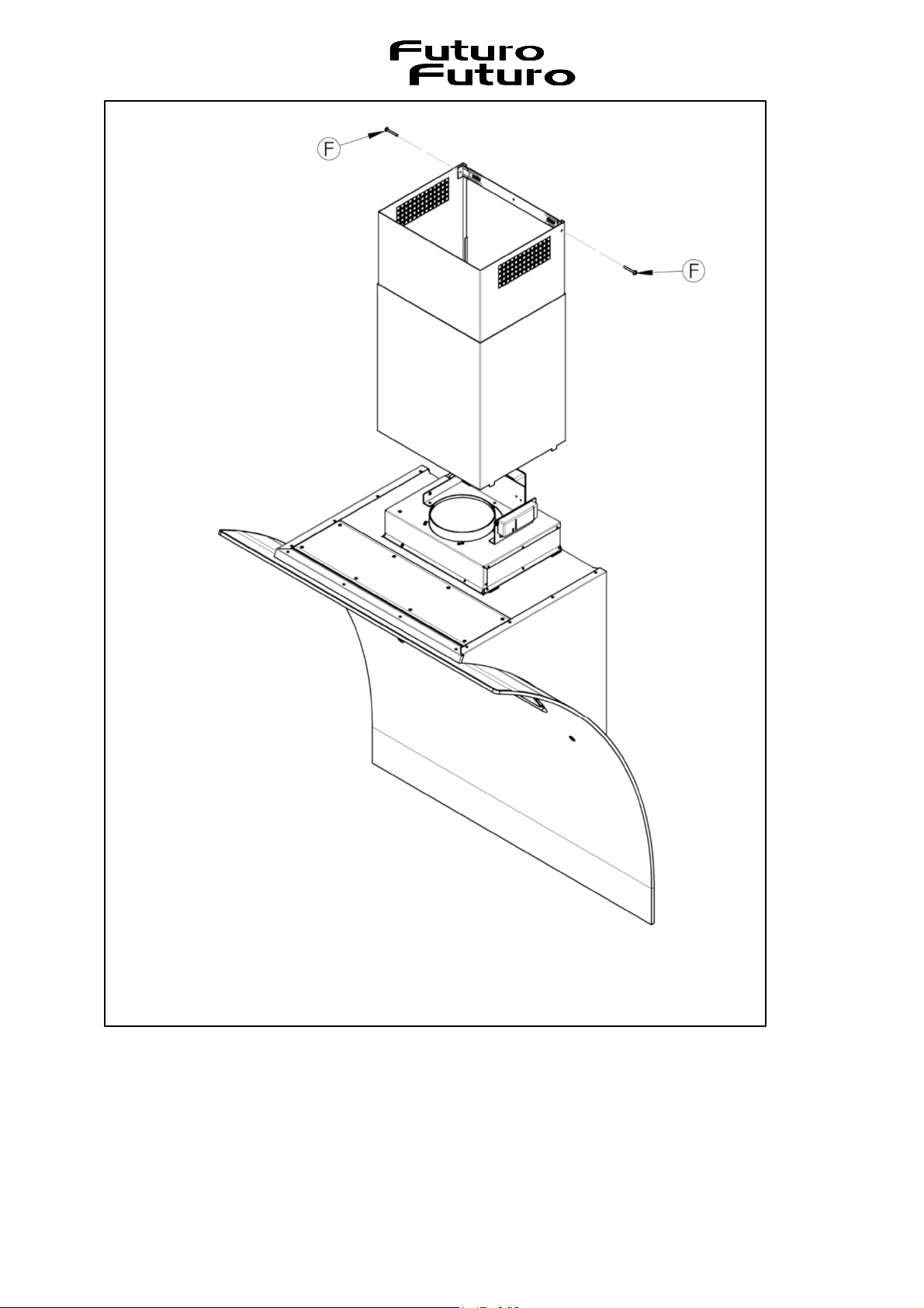
III.2 Fixing the wood to the wall
The unit (Fig. 3.2.1) is composed of the following elements:
1) Cooker hood body
2) Telescopic chimney
3) Perimetric glass
All fixtures are provided with the cookerhood.
During installation, place the hood delicately on the hob so as not to damage the glass.
To install the hood,
proceed as follows:
1) Draw and drill the wall as in Fig. 3.2.2.
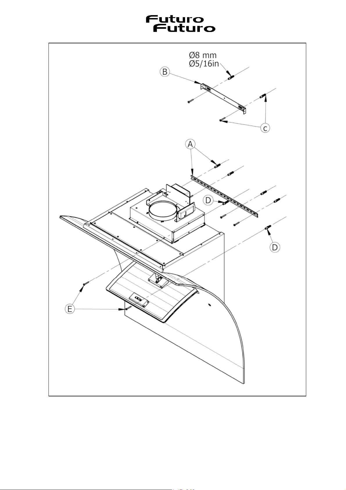
2) Fix on the wall the screw anchors with its support (Fig. 3.2.3-A).
3) Fix the support of the telescopic chimney (Fig. 3.2.3-B) with screw anchors (Fig. 3.2.3-C).
4) Put the screw anchors on the holes (Fig. 3.2.3-D).
5) Fix the hood to the screw anchors see point 2), two people are needed for this operation.
6) Open the glass panel, remove the anti-grease filter and block the equipment with screws (Fig. 3.2.3-E).
7) Apply the pipe and/or the drain connection.
8) Fix the telescopic chimney on the vents on the upper part of the hood and fix it to the support with screws (Fig.
3.2.4-F).
III.3 Electrical Connection
The electrical connection must be carried out ONLY by qualified technicians.
The electrical protection of the electrical connection upstream of the equipment must comply with the regulations in force.
Any change to the electrical installation necessary to install the hood should only be undertaken by qualified staff.
After installation, insulated parts and those carrying electricity must be protected from any possible contact.
Caution! If the electrical connection is carried out incorrectly or not meeting the regulations, it may
damage part of the appliance and the warranty will not be valid.
Warning! Before making the electrical connection, turn the main switch of the domestic system to "off".
These appliances must be earthed.
The appliance is supplied with plug and must be connected to the electrical system with a voltage of 120V and a
frequency of 60Hz.
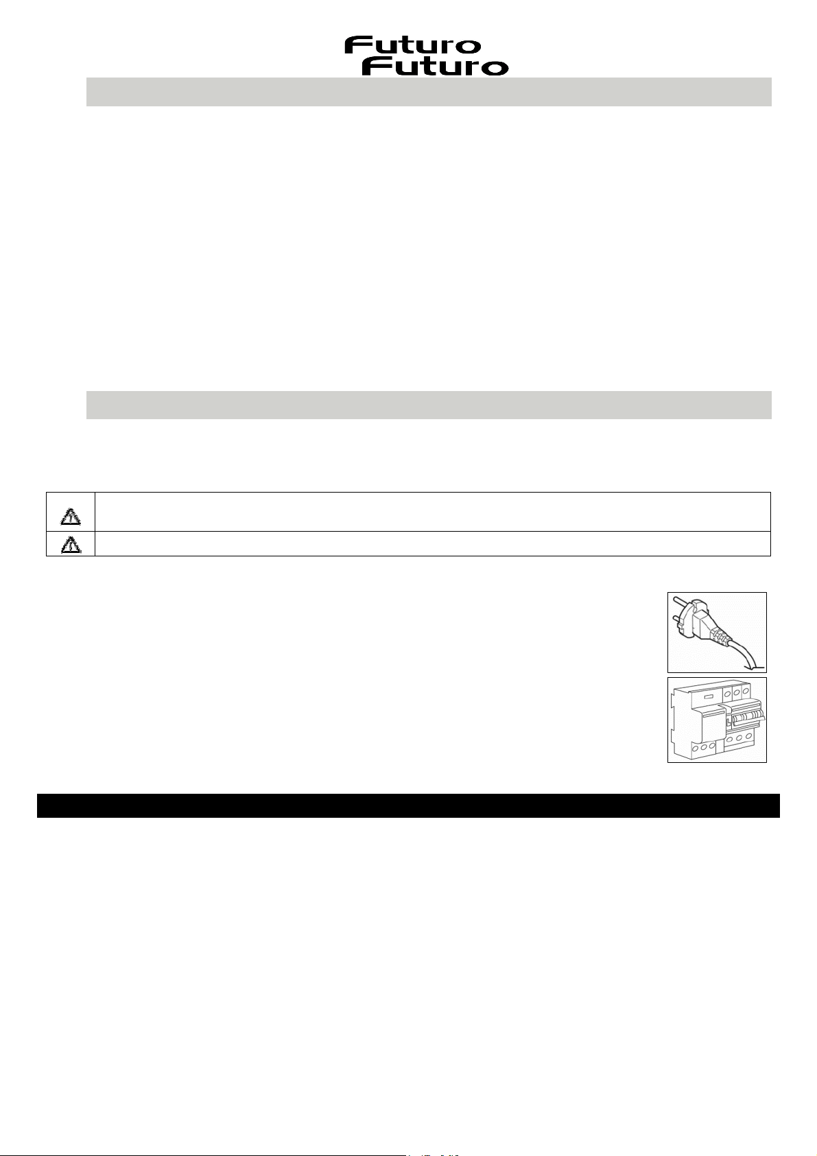
Two types of connections to the network are possible:
1.Using a standard plug connected (Fig. 3.3.1) to the power cord and inserted into an accessible
socket outlet (to be disconnected during service operations). Make sure that the plug is accessible
even after the complete installation of the appliance.
2.Stable connection to the network by interposing a bipolar switch to ensure disconnection from the
network, with a contact opening distance allowing complete disconnection under the conditions of
the overvoltage category III, by the installation rules (Fig. 3.3.2.).
Earth connection (yellow-green wire) should not be interrupted.
If the power cord is damaged, it must be replaced by the manufacturer or its authorized service
center or by a qualified technician, to prevent any risk.
IV USE
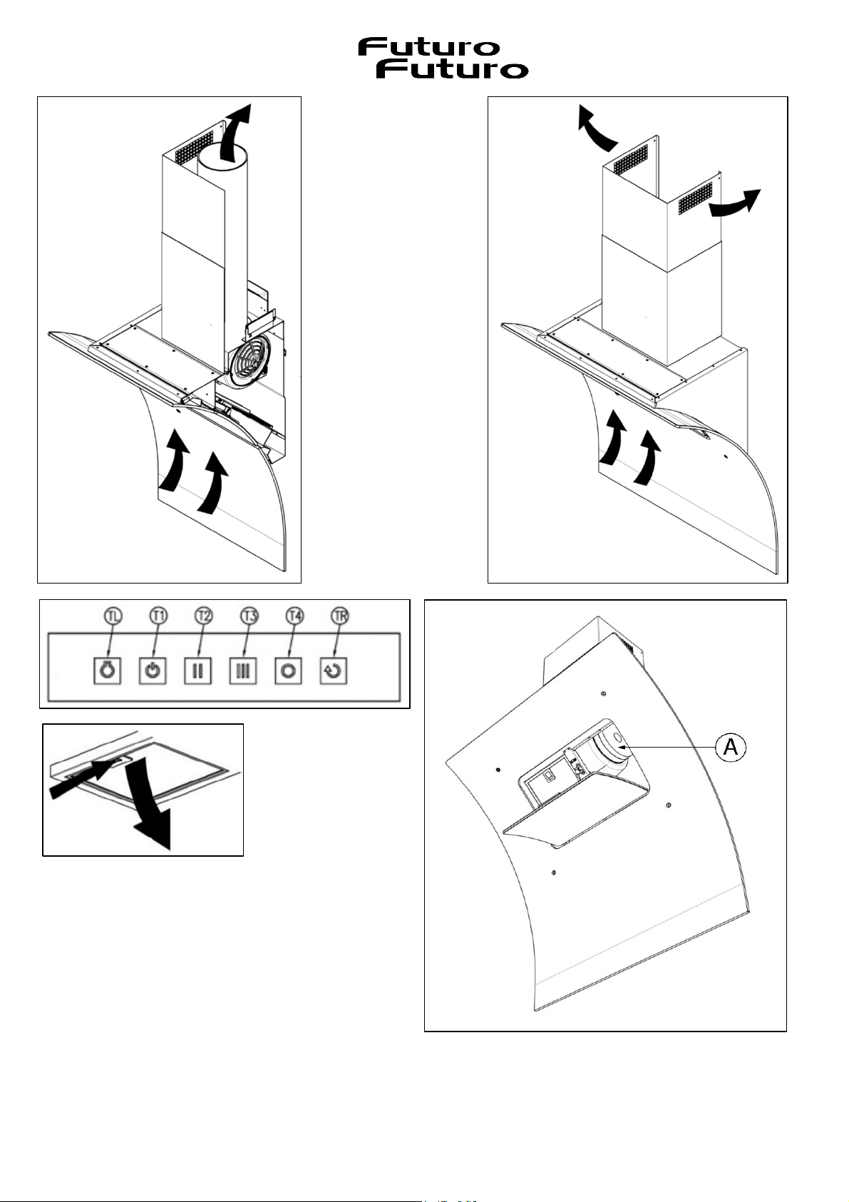
This cooker hood can be installed in ducted or filtering mode.
Ducted (external evacuation, Fig. 4.1). Remove any anti-odor filters if present. Kitchen smokes are vented outside through
a flue (not provided with the hood) joined to the exhaust pipe flue connector. This pipe must not under any circumstances
be connected to cooker, boiler or burner exhaust pipes, etc. Install this flue after completing what is described in the
INSTALLATION.
The use of pipes and holes on the wall with a smaller diameter than the motor output will cause a decrease
in suction performance and an increase in the noise level.
Use as short as possible tubes and with few curves. Use pipes with smooth internal surfaces
.
Filtering mode (ductless, Fig. 4.2). The cooking fumes pass through the activated carbon filters (not supplied with the hood,
Fig. 6.2.1-A) to be purified and recycled into the kitchen. The use of anti-odor filters reduces the performance of the hood.
3.3.1
3.3.2

6
V OPERATION
The hood is supplied with a multispeed blower. The hood should be run at low speed under normal conditions and at
higher speeds only when there is a heavy build-up of fumes or odours. Ideally, the hood should be switched on as soon
as cooking is started and then kept on until all odours have been eliminated.
V.I Hood control
Hood controls operation (Fig. 5.1.1):
TL button: illumination on and off.
T1 button: switching on the hood, selecting the first speed, switching off the blower.
T2-T3-T4 button: selection of the second, third and fourth speed of the blower
The LED of the key in operation remains lit steadily.
To turn the blower off when you are not at the first speed, press T1 twice.
A signal beep confirms receipt of the command. If T1 is off, T2, T3 and T4 do not activate the beep.
V.2 Adjustable and delayed self-switching off
This function allows to programme the delayed switch-off of the hood after cooking.
Causes total shutdown of lights and blower.
With the hood in operation, select the desired speed, then keep the TL button pressed for a few seconds until the
speed LEDs (T1, T2, T3, T4) start flashing indefinitely until the hood auto-off setting. By pressing one of the keys (T1,
T2, T3, T4) the delayed auto-off time can be programmed, as follows:
T1 corresponds to 5 minutes; T2 corresponds to 10 minutes; T3 corresponds to 15 minutes; T4 is 20 minutes.
During automatic shut-off operation, the set speed can be changed. If the choice of the switch-off time corresponds to
the set speed, the speed LED flashes; if the choice is different, the speed LED remains fixed.
During operation with auto-switch-off it is possible to deactivate the delayed switch-off by keeping the hood in
operation, keeping the button corresponding to the selected delayed time pressed.
During the auto-off function it is however possible to switch off the hood by pressing T1 twice.
During the auto-off function, TL and TR remain independent.
With the TL button active, the delayed auto-off function cannot be activated.
V.3 Maintenance reminder
Metal anti-grease filters
Every 30 hours of operation of the hood, when it is switched off, all the hood speed button LEDs light up with a steady
light for 30 seconds to alert the necessary cleaning of the metal grease filter. To reset the timer simply press and hold
the T4 button with the fan off. If the timer is not reset, all the LEDs will light up again each time the hood is switched
off again. You can reset the timer at any time.
Activated carbon filter (for filtering hoods)
Every 120 hours of operation of the hood, when it is switched off, all the LEDs of the hood speed button will switch on
for 30 seconds to remind the cleaning of the metal grease filters and, if the hood is in the filtering version, it is
necessary to replace the carbon filters. To reset the timer, simply press the T4 button with the fan off, otherwise the
the LED will flash again after each time the hood is switched off. You can reset the timer at any time.
V.4 24h Comfort function
This function allows the continuous air renewal in your kitchen when the hob and the range hood are not being used.
Air extraction cycles are activated at programmed time intervals: 5 min ON – 25 min OFF. These timed cycles clean the
air of any lingering odours as cigarette smoke, detergents and stagnant and stuffy smells. This function is easy to activate
and deactivate when required or can be left on for 24 hours.
To activate and deactivate this function, press TR key (Fig. 5.1.1).
The blower starts working for 5 minutes every 25 minutes at the first speed for a maximum of 24 hours.
During the suction phase the recirculation symbol flashes, otherwise it remains steady.
During operation it is possible to switch off the blower by deactivating the function using the TR button, otherwise
press T1 to return to first speed.
7
VI MAINTENANCE AND CLEANING
VI.1 Metal grease filter
Particular attention should be paid to the metal grease filter, which has the function of retaining the fat particles
contained in the vapors. The grease filter must be washed when the warning appears or at least once a month, use hot
water and detergent (or put it in the dishwasher). The filter may become discolored after a few washes. This is normal
and does not mean that it needs to be replaced.
To carry out maintenance on the grease filter, it is essential to remove it from the hood. With the hood turned off, the
filter can be removed by its handle (Fig. 6.1.1). At this point, you can proceed with the filter cleaning. It is recommended
to reinsert the grease filter only when it is perfectly dry.
VI.2 Activated carbon filters (for filtering hoods)
The activated carbon filters, if present, have the function of retaining the odors present in the cooking fumes.
The purified air is recycled into the room. The activated carbon filters must not be washed and must be replaced 3 or 4
times a year depending on the use of the hood. Request the filters to the manufacturer.
To install the activated carbon filters, the metal grease filter must first be removed (Fig. 6.1.1).
At this point, without the use of tools, install the activated carbon filters by hooking them to the interlocking tabs on
motor sides (Fig. 6.2.1-A). Then fix them by a 90° rotation for their insertion position in the tabs. To replace the activated
carbon filters, repeat the described operations backward.
VI.3 Hood Cleaning
The hood must be cleaned immediately after installation and removal of the protective film to eliminate any residual
adhesive or other impurities. The hood must be cleaned frequently both internally and externally (at least once a month).
Do not allow dirt to accumulate on the surfaces of the hood.
Do not use acid or basic products or abrasive sponges to clean the external parts of the hood. Clean the hood with a
sponge moistened with hot water and a small quantity of neutral soap (for example dish soap) to eliminate any grease
particles that may have deposited.
Rinse with a damp cloth, carefully remove all the soap, following the direction of the satin finish of the steel surface.
Drying is particularly important, especially in areas where the water is very hard and leaves limescale deposits.
VI.4 Lighting
The hood is equipped with LED lighting which, in addition to offering excellent lighting and limited energy consumption,
guarantee a considerable duration over time. In case of replacement, contact the assistance service.
VII DISCONTINUATION
The discontinuation means the definitive shutdown and disassembly of the appliance.
After discontinuation, the appliance can be installed on another piece of furniture, privately resold, or disposed of.
Caution! For discontinuation, it is necessary to switch the appliance off and disconnect the power
Disassembly requires that the device is accessible and has been disconnected from the power supply.
To do this, follow the installation instructions in reverse order.
Warning! Before any maintenance or cleaning operation, disconnect the hood from the power
supply by setting the main switch of the domestic system to "off".
ATTENTION: the grease collected in the filters can easily catch fire and it is therefore extremely
important to clean the metallic filters regularly as per instructions
8
3.1.1
3.2.1
9
3.2.2
10
3.2.3
11
3.2.4
12
395.813.1
5.1.1
4.1 DUCTED MOD
E
4.2 DUCTLESS MOD
E
6.2.1
6.1.1
