IMPORTANT MANUAL Do Not Throw Away
TM
OWNER'S MANUAL
MODEL:
PR17H42STA
LAWN TRACTOR
WARNING:
Read this Owner's Manual and follow
all Warnings and Safety Instructions.
Failure to do so can result in serious
injury.
ALWAYS WEAR EYE PROTECTION DURING OPERATION
279820 PR17H42ST,a, ,,_0,,,ov.,,,r,,n,,_o_,._._.'

SAFETY RULES
_lk 'Safe Operation Practices for Ride-On Mowers
IMPORTANT: THIS CUTTING MACHINE IS CAPABLE OF AMPUTATING HANDS AND FEET AND THROWING OBJECTS.
FAILURE TO OBSERVE THE FOLLOWING SAFETY INSTRUCTIONS COULD RESULT IN SERIOUS INJURY OR DEATH.
I. GENERALOPERATION
• Read, understand, and follow all instructions in the
manual and on the machine before starting.
• Only allowresponsibleadults, who are familiar withthe
instructions,to operate the machine.
• Clear the area of objects such as rocks, toys, wire,
etc., whichcouldbepickedupand thrown bythe blade.
• Be suretheareais clearofotherpeople before mowing.
Stop machine if anyone enters the area.
• Never carry passengers.
• Do not mow in reverse unless absolutely necessary.
Alwayslockdownand behindbeforeand while backing.
• Be aware ofthemower discharge direction and do not
point itat anyone. Do not operate the mower without
either the entire grass catcher or the guard in place.
• Slow downbeforeturning.
• Never leave a running machine unattended. Always
turn off blades, set parking brake, stop engine, and
remove keys before dismounting.
• Turn off bladeswhen not mowing.
• Stop engine before removing grass catcher or unclog-
ging chute.
• Mow onlyin daylight or good artificial light,
• Do not operate the machine while under the influence
of alcohol or drugs.
• Watch for traffic when operating near or crossing
roadways.
• Use extracare when loading or unloading the machine
into a trailer or truck.
• Data indicates thatoperators, age 60 years and above,
are involved in a large percentage of dding mower-
related injuries.These operatorsshould evaluate their
ability to operate the riding mower safely enough to
protect themselves and others from serious injury.
II. SLOPE OPERATION
Slopes are a major factor related to loss-of-control and
tipoveraccidents, whichcan resultinsevere injury ordeath.,
Allslopes require extracaution. Ifyou oannot back up the
slope or if you feel uneasy on it, do not mow it.
DO:
• Mow up and down slopes, not across.
• Remove obstacles such as rocks, tree limbs, etc.
• Watch for holes, ruts, or bumps, Uneven terrain could
overturn the machine. Tall grass can hide obstacles.
• Use slowspeed. Choose a low gear sothat you wiUnot
have to stop or shift while on the slope.
• Followthemanufacturer's recommendations forwheel
weights orcounterweights to improve stability.
• Use extra care with grass catchers or other attach-
ments. These canchange the stability of the machine.
• Keepallmovementontheslopesslowandgradua/. Do
not make sudden changes in speed or direction.
• Avoid starting or stopping on a slope. If tires lose
traction, disengage the blades and proceed slowly
straight downthe slope.
DO NOT:
• Do not turn on slopes unless necessary, and then, turn
slowlyand gradually downhill, if possible.
• Do not mow near drop-offs, ditches, or embankments.
The mower couldsuddenlyturnover ifawheel isoverthe
edge of a cliff or ditch, or if an edge caves in,
• Donotmowonwetgrass.Reducedtractioncouldcause
sliding.
• Do not tryto stabilize the machine by puttingyourfoot
onthe ground.
• Donotusegrasscatcheronsteepslopes.
III. CHILDREN
Tragic accidents can occur if the operator isnot alert to the
presence of children. Children are often attracted to the
machine and the mowing activity. Never assume that
children will remain where you last saw them.
• Keep children out of the mowing area and under the
watchful care of another responsible adult.
• Be alert and turn machine off if children enter the area.
• Before and when backing, look behind and down for
small children.
• Never carry children. They may fall off and be seriously
injured or interfere with safe machine operation,
• Never allow children to operate the machine.
• Use extra care when approaching blind comers, shrubs,
trees, or other objects that may obscure vision.
IV. SERVICE
• Use extra care in handling gasoline and other fuels.
They are flammable and vapors are explosive.
Use onlyan approved container.
Never remove gas cap or add fuel with the engine
running. Allow engine to cool before refueling. Do
not smoke.
Never refuel the machine indoors.
Never store the machine or fuel container inside
where there isanopen flame, suchas awater heater.
• Never run a machine inside a closed area.
• Keep nutsand bolts, especially blade attachment bolts,
tightand keep equipment in good condition.
• Never tamper with safety devices. Check their proper
operationregularly.
• Keep machine free of grass, leaves, or other debds
build-up. Clean oilorfuel spillage, Allowmachinetocool
before storing.
• Stop and inspect the equipment ifyou stdke an object.
Repair, ifnecessary, before restarting.
• Never make adjustments or repairs with the engine
running.
• Grass catcher components are subject to wear, dam-
age, and deterioration, whichcould exposemovingparts
orallow objectsto bethrown. Frequently check compo-
nents and replace with manufacturer's recommended
parts, when necessary.
• Mower blades are sharp and can cut. Wrapthe blade(s)
or wear gloves, and use extra caution when servicing
them.
• Check brake operation frequently. Adjust and service
as required.
2
A S.A.FETY RU.LES
Safe Operation Practices for Ride-On Mowers A
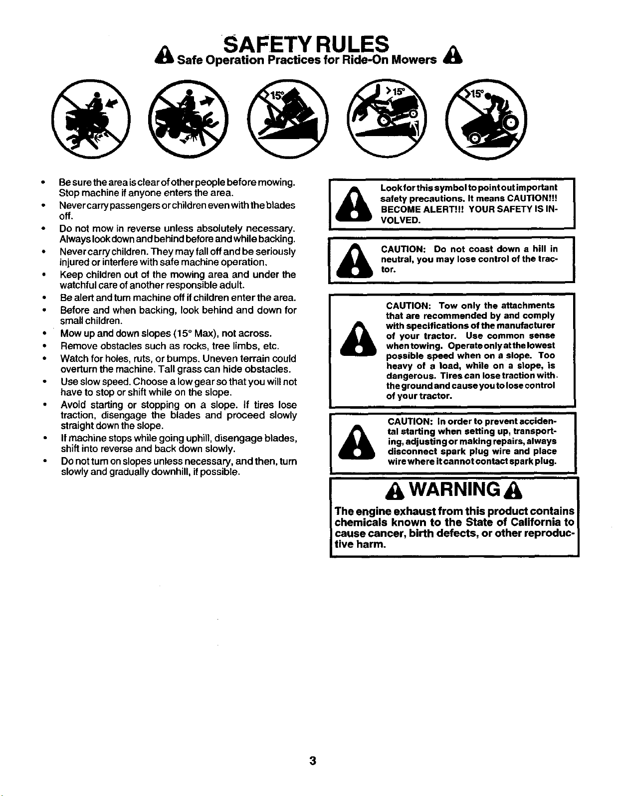
• Besurethe areais clear of otherpeople before mowing.
Stop machine ifanyone enters the area.
• Never carry passengers orchildreneven withthe blades
off.
• Do not mow in reverse unless absolutely necessary.
Always lookdownand behind beforeand while backing.
• Never carry children.They may fall offand be seriously
injured or interfere with safe machine operation.
• Keep children out of the mowing area and under the
watchful care ofanother responsible adult.
• Be alert and turnmachine off ifchildren enter the area.
• Before and when backing, look behind and down for
small children.
• Mow up and downslopes (15° Max), not across.
• Remove obstacles such as rocks, tree limbs, etc.
• Watch for holes, ruts,or bumps. Uneven terrain could
overturn the machine. Tall grass can hide obstacles.
• Use slow speed. Choose a lowgear so that you willnot
have to stop or shift while on the slope.
• Avoid starting or stopping on a slope, if tires lose
traction, disengage the blades and proceed slowly
straight downthe slope.
• Ifmachine stopswhile going uphill,disengage blades,
shift into reverse and back down slowly.
• Do not turnon slopes unless necessary, and then, turn
slowlyand gradually downhill, ifpossible.
IA
A
Look for this symbol to point out important I
safety precautions. It means CAUTION!!!
BECOME ALERT!t! YOUR SAFETY IS IN-
VOLVED.
CAUTION: Do not coast down a hill in
neutral, you may lose control of the trac-
tor.
A
CAUTION: Tow only the attachments
that are recommended by and comply
with specifications of the manufacturer
of your tractor. Use common sense
when towing. Operate only at the lowest
possible speed when on e slope. Too
heavy of a load, while on a slope, is
dangerous. Tires can lose traction with,
the ground and cause you to lose control
of your tractor.
A
CAUTION: In order to prevent acciden-
tal starting when setting up, transport-
ing, adjusting or making repairs, always
disconnect spark plug wire and place
wire where it cannot contact spark plug.
A WARNINGA
The engine exhaust from this product.contains
chemicals known to the State of California to
cause cancer, birth defects, or other reproduc-
tive harm.
3
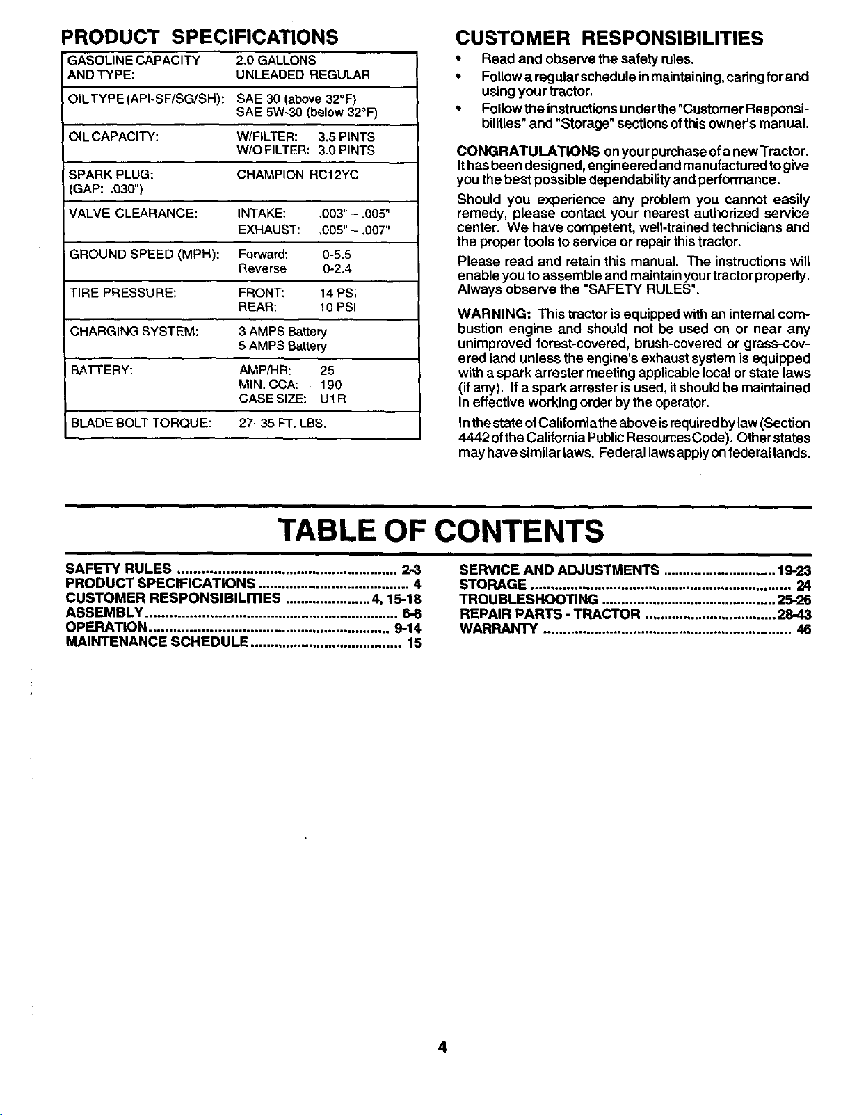
PRODUCT SPECIFICATIONS
GASOLINE CAPACITY 2.0 GALLONS
ANDTYPE: UNLEADED REGULAR
OILTYPE(API-SF/SG/SH): SAE 30 (above32°F)
SAE 5W-30 (below32°F)
OILCAPACITY: W/FiLTER: 3.5 PINTS
W/O FILTER: 3.0 PINTS
SPARK PLUG: CHAMPION RC12YC
(GAP: .030")
VALVE CLEARANCE: INTAKE: .003"-.005"
EXHAUST: .005"- .007"
GROUND SPEED (MPH): Forward: 0-5.5
Reverse 0-2.4
TIRE PRESSURE: FRONT: 14 PSI
REAR: 10 PSI
CHARGING SYSTEM: 3AMPS Battery
5 AMPS Battery
BATTERY: AMP/HR: 25
MIN. CCA: 190
CASESIZE: UIR
27-35 FT.LBS.
BLADE BOLT TORQUE:
CUSTOMER RESPONSIBILITIES
* Read and observe the safety rules.
• Followa regular schedule in maintaining, caringfor and
using your tractor,
• Followthe instructionsunder the"Customer Responsi-
bilities"and "Storage" sectionsofthis owner's manual.
CONGRATULATIONS onyour purchaseofa newTractor.
Ithasbeen designed, engineered and manufacturedtogive
you the best possible dependability and performance.
Should you expedence any problem you cannot easily
remedy, please contact your nearest authorized service
center. We have competent, well-trained technicians and
the proper tools to service or repairthis tractor.
Please read and retain this manual. The instructionswill
enable you to assemble and maintain yourtractorproperly.
Always observe the "SAFETY RULES".
WARNING: This tractor is equipped with an internal com-
bustion engine and should not be used on or near any
unimproved forest-covered, brush-covered or grass-cov-
ered land unless the engine's exhaust system isequipped
with a spark arrester meeting applicable local or state laws
(ifany). If a spark arrester isused, itshouldbe maintained
in effective working order bythe operator.
Inthe stateofCalifomiathe above isrequiredby law (Section
4442 ofthe California PublicResourcesCode). Other states
may have similar laws. Federal lawsapplyon federal lands.
TABLE OF CONTENTS
SAFETY RULES ..... 2.3
,,,.. ,..,,,...,.o,,,.,,,°,,,,,,o,,,.,.*,o,,o,.,o ,,,
PRODUCT SPECIFICATIONS ....................................... 4
CUSTOMER RESPONSIBILrrlES ...................... 4, 15-18
ASSEMBLY ................................................................ 6-8
OPERATION ............................................................. 9-14
MAINTENANCE SCHEDULE ....................................... 15
SERVICE AND ADJUSTMENTS ............................. 19.23
STORAGE ................................................................... 24
TROUBLESHOOTING ............................................. 25-26
REPAIR PARTS - TRACTOR .................................. 28-43
WARRANTY ................................................................ 46
4
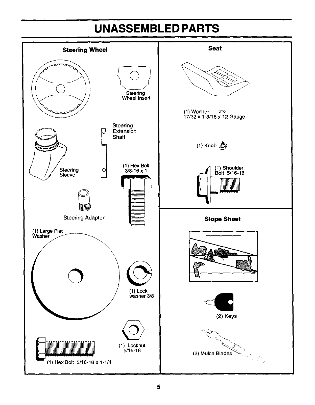
UNASSEMBLED PARTS
Seat
Steering Wheel
Steering
Wheel Insert
Sleeve l
Steering Adapter
Steenng
E_ension
Shaft
(1) Hex Bolt
3/8-16 x 1
P
(1) Large Flat
washer 3/8
(1) Locknut
5/16-18
- x 1-1/4
(1) Washer
17/32 x 1-3/16 x 12 Gauge
(1) Knob_
(1) Shoulder
Bolt 5/16-18
Slope Sheet
(2) Keys
(2) Mulch Bla_
•-
5
ASSEMBLY
Your new tractor has been assembled at the factory withexception ofthose parts leftunassembled for shipping purposes. To
ensure safe and proper operation ofyour tractor all parts and hardware you assemble mustbetightened securely. Use the
correct tools as necessary to insure proper tightness.
TOOLS REQUIRED FOR ASSEMBLY
A socket wrench set willmake assembly easier. Standard
wrench sizes are listed.
(1) 3/4" Socket w/drive ratchet Utility knife
(1) 9/16" wrenches Tirepressure gauge
(2) 1/2" wrenches PhillipsScrewdriver
When fight orlefthand ismentioned inthismanual, itmeans
when you are in the operating position(seated behind the
steedng wheel).
TO REMOVETRACTOR FROM CARTON
UNPACK CARTON
• Remove all accessible loose parts and parts cartons
from carton.
• Cut, from top to bottom, along lineson all four comers
of carton, and lay panels flat.
• Check for any additional loose parts or cartons and
remove.
BEFORE REMOVING TRACTOR FROM
SKID
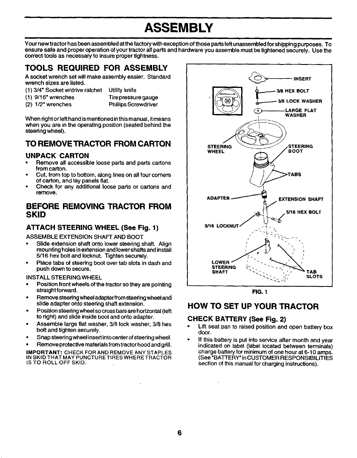
ATTACH STEERING WHEEL (See Fig. 1)
ASSEMBLE EXTENSION SHAFT AND BOOT
• Slide extension shaft onto lower steering shaft. Align
mounting holesinextension and lowershaftsand install
5/16 hex bolt and Iocknut. Tighten securely.
• Piece tabs of steering boot over tab slots in dash and
push down to secure.
INSTALL STEERING WHEEL
• Position front wheels ofthe tractorsothey are pointing
straightforward,
• Remove steedngwheel adapterfrom steeringwheel and
slide adapter onto steering shaft extension.
• Position steering wheel socrossbarsare horizontal (left
to right) and slide inside boot and onto adapter.
• Assemble large fiat washer, 3/8 lock washer, 3/8 hex
bolt and tighten securely.
• Snap steedng wheel insertintocenter ofsteedngwheel.
• Remove protective materials fromtractorhoodand griU.
IMPORTANT: CHECK FOR AND REMOVE ANY STAPLES
IN SKID THAT MAY PUNCTU RETIRES WHERE TRACTOR
IS TO ROLL OFF SKID,
STEERING
WHEEL
STEERING
BOOT
TABS
ADAPTER ...-...------i EXTENSION SHAFT
7
-_ 5116 HEX BOLT
5/16 LOCKNUT_'_ _
STEERINQ_". "" - __, _._\
SHAFT _._,.". , ,_ _' TAB
_'__, I_' SLOTS
FIG. 1
HOW TO SET UP YOUR TRACTOR
CHECK BATTERY (See Fig. 2)
• Lift seat pan to raised position and open battery box
door.
• If this battery is put into service after month and year
indicated on label (label located between terminals)
charge battery for minimum ofone hour at 6-10 amps.
(See"BA'I-I'ERY" inCUSTOMER RESPONSIBILITIES
section ofthis manual for charging instructions).
6
ASSEMBLY
BOX
FIG. 2
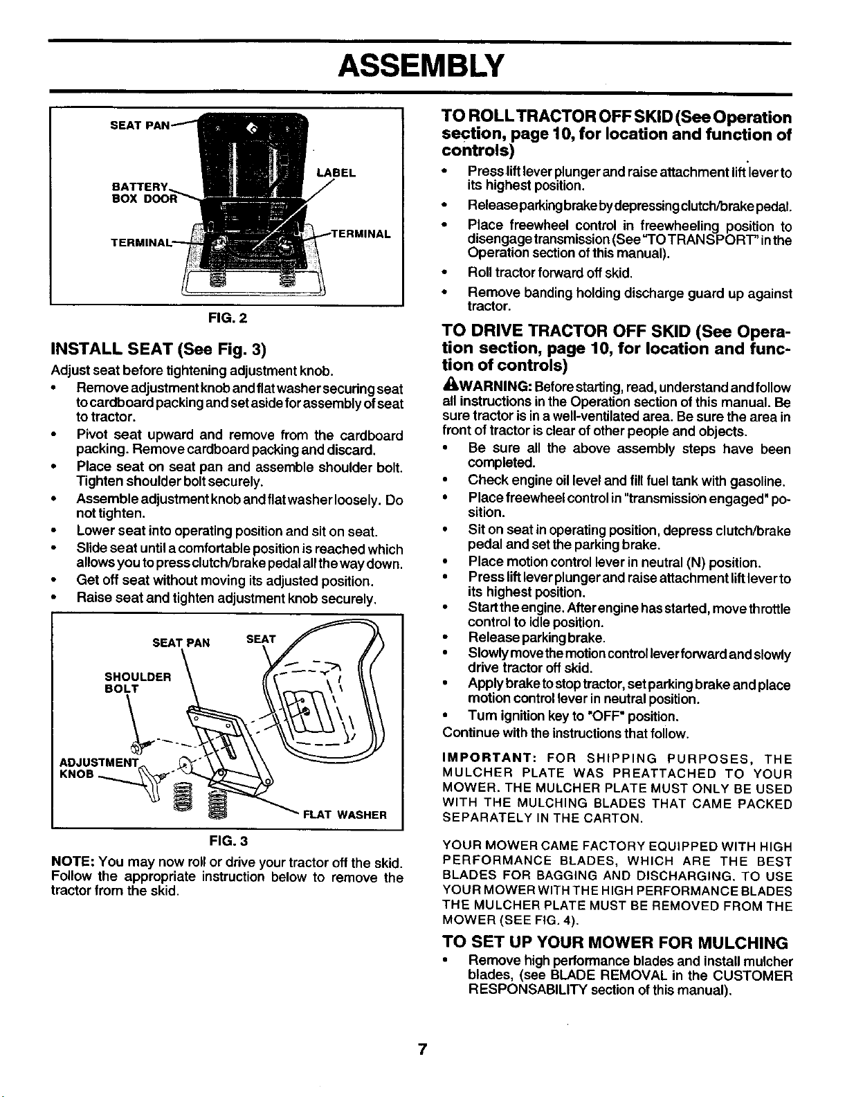
INSTALL SEAT (See Fig. 3)
Adjust seat before tighteningadjustment knob.
• Remove adjustment knoband flatwasher secudng seat
tocardboard packing and set asideforassembly ofseat
totractor.
• Pivot seat upward and remove from the cardboard
packing. Remove cardboard packingand discard.
• Place seat on seat pan and assemble shoulder bolt.
Tighten shoulder boltsecurely.
• Assemble adjustment knoband flatwasher loosely. Do
not tighten.
• Lower seat into operating positionand sit on seat.
• Slide seat untila comfortable positionisreached which
allowsyou to pressclutch/brake pedalall theway down.
• Get off seat without moving itsadjusted position.
• Raise seat and tighten adjustment knob securely.
SEAT PAN SEAT
SHOULDER
BOLT
ADJUSTMENT
FLAT WASHER
FIG. 3
NOTE: You may now rollor ddve your tractor offthe skid.
Follow the appropriate instruction below to remove the
tractor from the skid.
TO ROLLTRACTOR OFF SKID (See Operation
section, page 10, for location and function of
controls)
• Press liftleverplunger and raise attachment lift'leverto
its highest position.
• Release parkingbrakebydepressingclutch/brakepedal
• Place freewheel control in freewheeling position to
disengage transmission(See =TOTRANSPORT" inthe
Operation sectionof this manual).
• Roll tractor forward offskid.
• Remove banding holding discharge guard up against
tractor.
TO DRIVE TRACTOR OFF SKID (See Opera-
tion section, page 10, for location and func-
tion of controls)
_WARNING: Beforestarting,read, understand and follow
all instructions in the Operation section of this manual. Be
sure tractor isin a well-ventilated area. Be sure the area in
front of tractor isclear of other people and objects.
• Be sure all the above assembly steps have been
completed.
• Check engine oil level and fillfuel tank with gasoline.
• Place freewheel controlin "transmission engaged" po-
sition.
• Sit on seat in operating position,depress clutch/brake
pedal and set the parkingbrake.
• Place motioncontrol lever in neutral (N) position.
• Press liftleverplunger and raise attachment liftlever to
its highest position.
• Start theengine.Afterengine hasstarted, move throttle
control to idleposition.
• Release parkingbrake.
• Slowly movethemotioncontrolleverforward and slowly
drive tractor offskid.
• Apply brake tostoptractor,set parkingbrake and place
motion controllever in neutral position.
• Turn ignitionkey to "OFF" position.
Continue with the instructionsthat foliow.
IMPORTANT: FOR SHIPPING PURPOSES, THE
MULCHER PLATE WAS PREATTACHED TO YOUR
MOWER. THE MULCHER PLATE MUST ONLY BE USED
WITH THE MULCHING BLADES THAT CAME PACKED
SEPARATELY IN THE CARTON.
YOUR MOWER CAME FACTORY EQUIPPED WITH HIGH
PERFORMANCE BLADES, WHICH ARE THE BEST
BLADES FOR BAGGING AND DISCHARGING. TO USE
YOUR MOWER WITH THE HIGH PERFORMANCE BLADES
THE MULCHER PLATE MUST BE REMOVED FROM THE
MOWER (SEE FIG. 4).
TO SET UP YOUR MOWER FOR MULCHING
• Remove highperformance blades and install mulcher
blades, (see BLADE REMOVAL in the CUSTOMER
RESPONSABILITY section ofthis manual).
7
ASSEMBLY
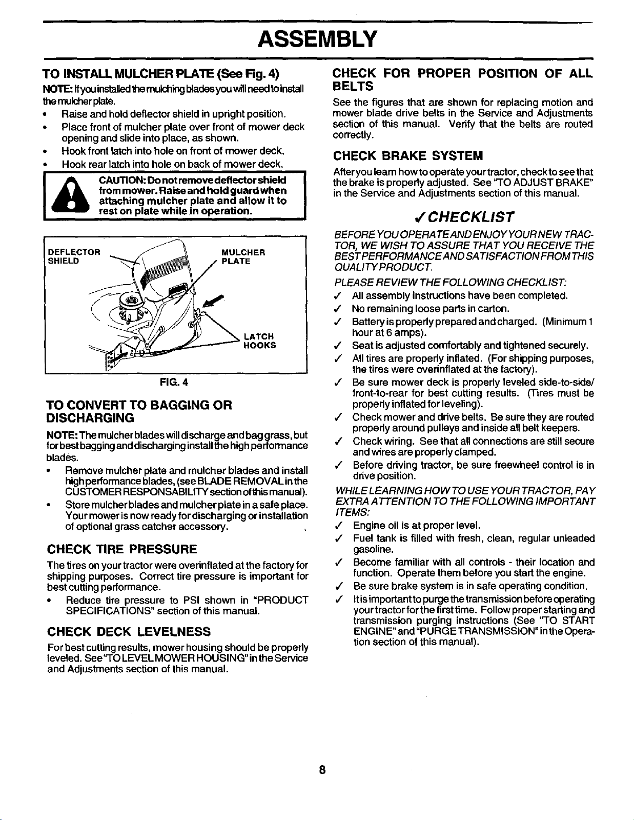
TO INSTALL MULCHER PLATE (See Rg. 4)
NOTE: Ifyouinstalledthemulchingbladesyouwillneed toinstall
themulcherplate.
• Raise and hold deflector shield in upright position.
• Place front of mulcher plate over front of mower deck
opening and slideinto place, as shown.
• Hook front latch into hole on front of mower deck.
• Hook rear latch into hole on back of mower deck,
I_ AUTION: _ not _'nove d_-'tor shmld I
from mower. Raise and hold guard when
attaching mulcher plate and allow it to
rest on plate while in operation.
DEFLECTOR MULCHER
SHIELD PLATE
LATCH
HOOKS
FIG. 4
TO CONVERT TO BAGGING OR
DISCHARGING
NOTE: The mulcher blades willdischarge and baggrass, but
for bestbaggingand discharginginstallthe highperformance
blades.
• Remove mulcher plate and mulcher blades aDd install
highperformanceblades, (see BLADE REMOVAL inthe
CUSTOMER RESPONSABILITY sectionofthismanual).
• Store mulcherblades and mulcher plate in a safe place.
Your mower isnow ready for discharging or installation
of optional grass catcher accessory.
CHECK TIRE PRESSURE
The tires on yourtractor were overinflated at the factory for
shipping purposes. Correct tire pressure is important for
bestcutting performance.
• Reduce tire pressure to PSI shown in "PRODUCT
SPECIFICATIONS" section of this manual.
CHECK DECK LEVELNESS
For best cuttingresults, mower housing should be propedy
leveled. See'qO LEVEL MOWER HOUSING"in the Service
and Adjustments section of this manual.
CHECK FOR PROPER POSITION OF ALL
BELTS
See the figures that are shown for replacing motion and
mower blade drive belts in the Service and Adjustments
section of this manual. Verify that the belts are muted
correctly.
CHECK BRAKE SYSTEM
Afteryou learn howto operate your tractor,check tosee that
the brake is properly adjusted. See "TO ADJUST BRAKE"
in the Service and Adjustments section of this manual.
,f CHECKLIST
BEFORE YOU OPERA TEAND ENJO Y YOUR NEW TRAC-
TOR, WE WISH TO ASSURE THAT YOU RECEIVE THE
BEST PERFORMANCE AND SA TISFAC TION FROM THIS
QUALITY PRODUCT.
PLEASE REVIEW THE FOLLOWING CHECKLIST:
,/ All assembly instructions have been completed.
,/ No remaining loose parts in carton.
,/ Batteryis properly prepared and charged. (Minimum 1
hour at 6 amps).
,/ Seat is adjusted comfortably and tightened securely.
,/ All tires are properly inflated. (For shipping purposes,
the tires were overinflated at the factory).
,/ Be sure mower deck is properly leveled side-to-side/
front-to-rear for best cutting results. (Tires must be
properly inflated for leveling).
•/ Check mower and drive belts. Be sure they are routed
properly around pulleys and inside all belt keepers.
,/ Check wiring. See that all connections are stillsecure
and wires are properly clamped.
•/ Before driving tractor, be sure freewheel control is in
drive position.
WHILE LEARNING HOW TO USE YOUR TRACTOR, PAY
EXTRA ATTENTION TO THE FOLLOWING IMPORTANT
ITEMS:
•/ Engine oil is at proper level.
,/' Fuel tank is filled with fresh, clean, regular unleaded
gasoline.
,/ Become familiar with all controls - their location and
function. Operate them before you start the engine.
,/ Be sure brake system is in safe operating condition.
,/ Itis important to purge the transmission before operating
your tractor for the first time. Follow proper starting and
transmission purging instructions (See 'q'O START
ENGINE" and"PURGE TRANSMISSION" inthe Opera-
tion section of this manual).
8
OPERATION
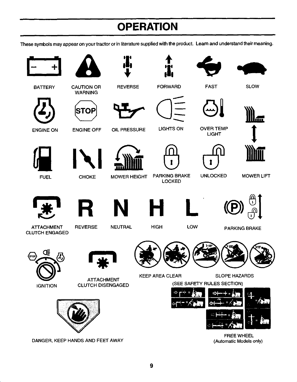
These symbols may appear on your tractor or inliterature supplied with the product. Learn and understand their meaning.
BAI-FERY CAUTION OR REVERSE FORWARD FAST SLOW
WARNING
ENG,NEONENG,NEOFFO,LPRESSOREL,GHTSONO%_MP
FUEL CHOKE MOWER HEIGHT PARKING BRAKE UNLOCKED MOWER LIFT
LOCKED
N H L
AI-rACHMENT REVERSE NEUTRAL HIGH LOW
CLUTCH ENGAGED
IGNITION
A'I-I-ACHMENT
CLUTCH DISENGAGED
PARKING BRAKE
KEEP AREA CLEAR SLOPE HAZARDS
(SEE SAFETY RULES SECTION)
DANGER, KEEP HANDS AND FEET AWAY
FREE WHEEL
(Automatic Modelsonly)
9
OPERATION
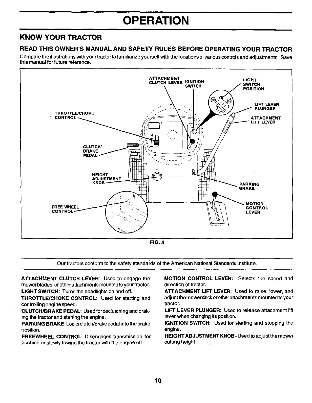
KNOW YOUR TRACTOR
READ THIS OWNER'S MANUAL AND SAFETY RULES BEFORE OPERATING YOUR TRACTOR
Compare the illustrationswith yourtractortofamiliarize youreelf with the locationsofvarious controlsand adjustments. Save
this manual for future reference.
THROTTL_CHOKE
CONTR(
CLUTCH/ _.
BRAKE_
PEDAL _-
HEIGHT
ADJUSTMENT
KNOB
FREE WHEEL
ATTACHMENT
CLUTCH LEVER IGNITION
LIGHT
SWITCH J SWITCH
f POSITION
_' LIFT LEVER
::. JP'UNGER
_ _ " _ PARKING
_=_/ LEVER
FIG. 5
Our tractors conform to the safety standards ofthe American National Standards institute.
ATTACHMENT CLUTCH LEVER: Used to engage the
mower blades, orotherattachments mountedtoyourtractor.
LIGHT SWITCH: Turns the headlights on and off.
THROTTLE/CHOKE CONTROL: Used for starting and
controllingengine speed.
CLUTCH/BRAKE PEDAL: Used for declutchingand brak-
ing the tractor and starting the engine.
PARKING BRAKE: Locksclutch/brakepedal intothe brake
position.
FREEWHEEL CONTROL: Disengages transmission for
pushing or slowly towing the tractor withthe engine off.
MOTION CONTROL LEVER: Selects the speed and
direction oftractor.
AI-FACHMENT LIFT LEVER: Used to raise, lower, and
adjust themower deckorotherattachments mounted toyour
tractor.
LIFT LEVER PLUNGER: Used to release attachment lift
lever when changing itsposition.
IGNITION SWITCH: Used for starting and stopping the
engine.
HEIGHT ADJUSTMENT KNOB -Used toadjustthe mower
cutting height.
10
OPERATION
The operation ofany tractor can result in foreign objects thrown into the eyes, which can
result in severe eye damage. Always wear safety glasses or eye shields while operating
your tractor or performing any adjustments or repairs. We recommend a wide vision
safety mask over spectacles or standard safety glasses.
HOW TO USE YOUR TRACTOR
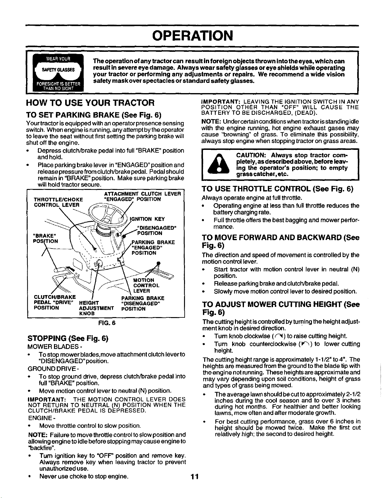
TO SET PARKING BRAKE (See Fig. 6)
Yourtractor isequipped with anoperator presence sensing
switch. When engine is running,anyattempt by theoperator
to leave the seat without first setting the parking brake will
shut off the engine.
• Depress clutch/brake pedal into full "BRAKE" position
and hold.
• Place parking brake lever in "ENGAGED" position and
release pressure from clutch/brake pedal. Pedal should
remain in "BRAKE" position. Make sure parking brake
will hold tractor secure.
THROTTL_CHOKE
CONTROL LEVER
ATTACHMENT CLUTCH LEVER
"ENGAGED" POSITION
KEY
BRAKE
lED"
POSITION
CONTROL
LEVER
CLUTCH/BRAKE PARKING BRAKE
PEDAL "DRIVE" HEIGHT "DISENGAGED"
POSITION ADJUSTMENT POSITION
KNOB
FIG. 6
STOPPING (See Fig. 6)
MOWER BLADES -
• To stop mower blades,move attachment clutch leverto
"DISENGAGED" position.
GROUND DRIVE-
• To stop ground drive, depress clutch/brake pedal into
full "BRAKE" position.
• Move motion control lever toneutral (N) position.
IMPORTANT: THE MOTION CONTROL LEVER DOES
NOT RETURN TO NEUTRAL (N) POSITION WHEN THE
CLUTCH/DRAKE PEDAL IS DEPRESSED.
ENGINE -
• Move throttle control to slow position.
NOTE: Failure to move throttle control to slow position and
allowing engine to idle before stopping may cause engine to
"backfire".
• Turn ignition key to "OFF' position and remove key.
Always remove key when leaving tractor to prevent
unauthodzed use.
• Never use choke to stop engine.
IMPORTANT: LEAVING THE IGNITION SWITCH IN ANY
POSITION OTHER THAN "OFF" WILL CAUSE THE
BATTERY TO BE DISCHARGED, (DEAD).
NOTE: Under certain conditions when tractor isstanding idle
with the engine running, hot engine exhaust gases may
cause "browning" of grass. To eliminate this possibility,
always stop engine when stopping tractor on grass areas.
i
CAUTION: Always stop tractor com-
pletely, as described above, before leav-
ing the operator's position; to empty
grass catcher,etc.
TO USE THRO'n'LE CONTROL (See Fig. 6)
Always operate engine at full throttle.
• Operating engine at less than full throttle reduces the
battery charging rate.
• Full throttle offers the best bagging and mower perfor-
mance.
TO MOVE FORWARD AND BACKWARD (See
Fig. 6)
The direction and speed of movement is controlled by the
motion control lever.
• Start tractor with motion control lever in neutral (N)
position.
• Release parkingbrake and clutch/brake pedal,
• Slowly move motion control lever to desired position.
TO ADJUST MOWER CUTTING HEIGHT (See
Fig. 6)
The cutting height iscontrolledbyturningthe height adjust-
ment knob in desired direction.
• Tum knob clockwise (_) to raise cutting height.
• Turn knob counterclockwise (_)to lower cutting
height.
The cutting height range isapproximately 1-1/2" to4". The
heights are measured from the ground tothe blade tip with
the engine notrunning. These heights areapproximate and
may vary depending upon soil conditions, height of grass
and types of grass being mowed.
• The average lawn should be cut to approximately 2-1/2
inches during the cool season and to over 3 inches
during hot months. For healthier and better looking
lawns, mow often and after moderate growth.
For best cutting performance, grass over 6 inches in
height should be mowed twice. Make the first cut
relatively high; the second to desired height.
11
OPERATION
TO OPERATE ON HILLS
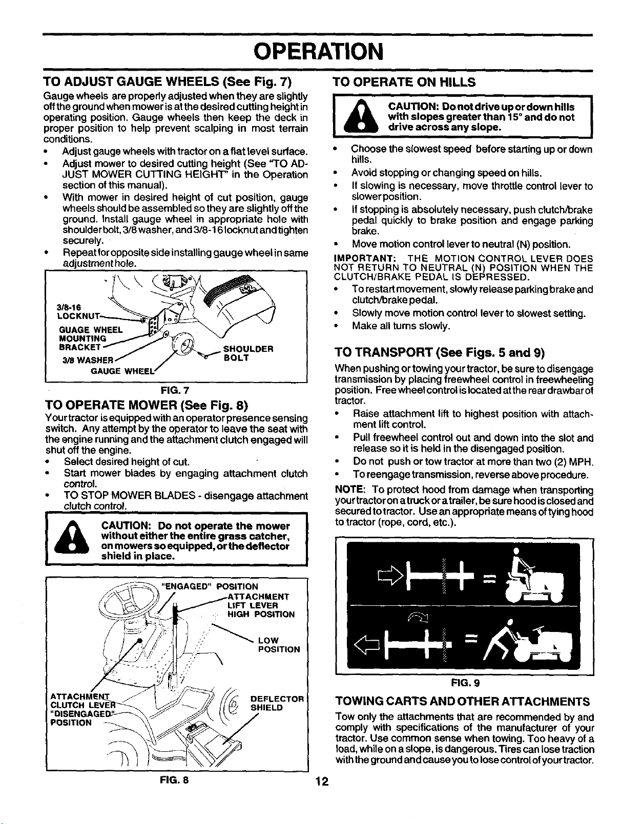
TO ADJUST GAUGE WHEELS (See Fig. 7)
Gauge wheels are propedy adjusted when they are slightly
offtheground when mower isat the desired cutting height in
operating position, Gauge wheels then keep the deck in
proper position to help prevent scalping in most terrain
conditions.
• Adjust gauge wheels withtractor on a flat level surface.
• Adjust mower to desired cutting height (See "TO AD-
JUST MOWER CUTTING HEIGHT" in the Operation
section ofthis manual).
• With mower in desired height of cut position, gauge
wheels shouldbe assembled sothey are slightly offthe
ground. Install gauge wheel in appropriate hole with
shoulder bolt, 3/8 washer, and 3/8-16 Iocknut and tighten
securely.
• Repeat for opposite side installing gauge wheel in same
adjustment hole.
3/8-16
GUAGE WHEEL
318
GAUGE
SHOULDER
BOLT
FIG. 7
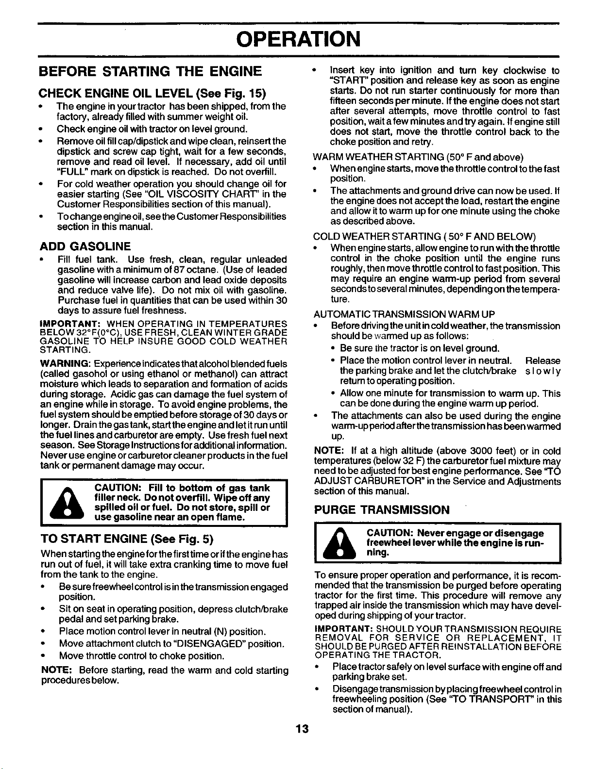
TO OPERATE MOWER (See Fig. 8)
Your tractor isequipped withan operator presence sensing
switch. Any attempt bythe operator to leave the seat with
the engine runningand the attachment clutch engaged will
shut off the engine.
• Select desired height ofcut.
• Start mower blades by engaging attachment clutch
control.
• TO STOP MOWER BLADES - disengage attachment
clutch control.
I CA°T'o":oonotopera'eth"°°wetI
without either the entire grass catcher,
on mowers so equipped, or the deflector
shield in place.
I& I
CAUTION: Do not drive up or down hills
with slopes greater than 15° and do not
drive across any slope.
• Choose the slowest speed before starting up or down
hills,
• Avoid stopping or changing speed on hills.
• If slowing is necessary, move throttle control lever to
slower position.
• If stopping is absolutely necessary, push clutch/brake
pedal quickly to brake position and engage parking
brake.
• Move motion control lever to neutral (N) position.
IMPORTANT: THE MOTION CONTROL LEVER DOES
NOT RETURN TO NEUTRAL (N) POSITION WHEN THE
CLUTCH/BRAKE PEDAL IS DEPRESSED.
• To restart movement, slowly release parking brake and
clutch/brake pedal.
• Slowly move motion control lever to slowest setting.
• Make all tums slowly.
TO TRANSPORT (See Figs. 5 and 9)
When pushing or towing your tractor, be sure todisengage
transmission by placing freewheel control infreewheeling
position. Free wheel controlislocated atthe raardrawbar of
tractor.
• Raise attachment lift to highest position with attach-
ment lift control.
• Pull freewheel control out and down into the slot and
release so it is held in the disengaged position.
• Do not push or tow tractor at more than two (2) MPH.
• To reengagetransmission, reverse above procedure.
NOTE: To protect hood from damage when transporting
yourtractoronatruckor atrailer, be sure hoodisclosed and
secured totractor. Use an appropriate means oftyinghood
to tractor (rope, cord, etc.).
CLUTCH
POSITION
LIFT LEVER
: HIGH POSITION
DEFLECTOR
SHIELD
FIG. 9
TOWING CARTS AND OTHER ATTACHMENTS
Tow only the attachments that are recommended by and
comply with specifications of the manufacturer of your
tractor. Use common sense when towing. Too heavy of a
load, while on a slope, isdangerous. Tires can losetraction
withthe groundand cause youto losecontrolofyourtractor.
FIG. 8 12
OPERATION
BEFORE STARTING THE ENGINE •
CHECK ENGINE OIL LEVEL (See Fig. 15)
• The engine inyourtractor has been shipped, from the
factory, already filled with summer weight oil.
• Check engine oilwith tractor on level ground.
• Remove oilfillcap/dipstickand wipe clean, reinsert the
dipstick and screw cap tight, wait for a few seconds,
remove and read oil level. If necessary, add oil until
"FULl." mark on dipstick isreached. Do not overfill.
• For cold weather operation you should change oilfor
easier starting (See "OIL VISCOSITY CHART" in the
Customer Responsibilitiessection of this manual).
• To change engineoil,see theCustomer Responsibilities
section in this manual.
ADD GASOLINE
• Fill fuel tank. Use fresh, clean, regular unleaded
gasoline with a minimumof87 octane. (Use of leaded
gasoline will increasecarbon and lead oxide deposits
and reduce valve life). Do not mix oil with gasoline.
Purchase fuel in quantitiesthat can be used within 30
days to assure fuel freshness.
IMPORTANT: WHEN OPERATING IN TEMPERATURES
BELOW 32°F(0°C), USE FRESH, CLEAN WINTER GRADE
GASOLINE TO HELP INSURE GOOD COLD WEATHER
STARTING.
WARNING: Experience indicates thatalcoholblended fuels
(called gasohol or using ethanol or methanol) can attract
moisture which leads toseparation and formation of acids
dudng storage. Acidic gas can damage the fuel system of
an engine while in storage. To avoid engine problems, the
fuel system shouldbeemptied before storage of30 days or
longer. Drain the gastank, starttheengine and letitrununtil
the fuel lines and carburetor are empty. Use fresh fuel next
season. See Storage Instructionsfor additional information.
Never use engine orcarburetor cleaner products inthe fuel
tank or permanent damage may occur.
I&
CAUTION: Fill to bottom of gas tank
filler neck. Donotoverfill. Wipeoffany
spilled oil or fuel. Do not store, spill or
use gasoline near an open flame.
TO START ENGINE (See Fig. 5)
When startingthe engineforthefirsttime orifthe engine has
run out of fuel, it willtake extra cranking time to move fuel
from the tank to the engine.
• Be sure freewheel contrelisinthetransmissionengaged
position.
• Sit on seat in operating position, depress clutch/brake
pedal and set parkingbrake.
• Place motion controllever in neutral (N) position.
• Move attachment clutchto "DISENGAGED" position.
• Move throttle controlto choke position.
NOTE: Before starting, read the warm and cold starting
procedures below.
Insert key into ignition and tum key clockwise to
"START" position and release key as soon as engine
starts. Do not run starter continuously for more than
fifteen secondsper minute. Ifthe engine does not start
after several attempts, move throttle control to fast
position,waitafew minutes and tryagain. Ifengine still
does not start, move the throttle control back to the
choke positionand retry.
WARM WEATHER STARTING (50° F and above)
• When engine starts, move thethrottle control to thefast
position.
• The attachments and ground drive can now be used. If
the engine does not accept the load, restart the engine
and allow ittowarm up for one minute using the choke
as describedabove.
COLD WEATHER STARTING ( 50 ° F AND BELOW)
• When engine starts, allow engine to run with the throttle
control in the choke position until the engine runs
roughly,then move throttlecontrol tofast position.This
may require an engine warm-up pedod from several
secondstoseveralminutes, depending on thetempera-
ture.
AUTOMATIC TRANSMISSION WARM UP
• Before ddving the unit in cold weather, the transmission
should be warmed up as follows:
• Be sure thetractor is on level ground.
• Place the motion control lever in neutral. Release
the parking brake and let the clutch/brake s Io w Iy
return to operating position.
• Allow one minute for transmission to warm up. This
can be done during the engine warm up period.
• The attachments can also be used during the engine
warm-up pedod after the transmission has been warmed
up.
NOTE: If at a high altitude (above 3000 feet) or in cold
temperatures (below32 F) the carburetor fuel mixture may
need to be adjustedfor best engine performance. See "TO
ADJUST CARBURETOR" in the Service and Adjustments
section of this manual.
PURGE TRANSMISSION
I& AUTION: Neverengageordisengage I
freewheel lever while the engine is run-
ning.
To ensure proper operation and performance, it isrecom-
mended that thetransmission be purged before operating
tractor for the first time. This procedure will remove any
trapped air insidethe transmission which may have devel-
oped during shippingofyour tractor.
IMPORTANT: SHOULD YOUR TRANSMISSION REQUIRE
REMOVAL FOR SERVICE OR REPLACEMENT, IT
SHOULD BE PURGEDAFTER REINSTALLATION BEFORE
OPERATING THE TRACTOR.
• Place tractorsafelyon level surface with engine offand
parking brake set.
• Disengage transmission byplacingfreewheel controlin
freewheeling position (See "TO TRANSPORT" in this
section of manual).
13
OPERATION
• Sitting inthe tractor seat, start engine. After the engine
is running, move throttle control to slow position. With
motion control lever in neutral (N) position, slowly
disengage clutch/brake pedal.
• Move motion control lever to full forward position and
hold for five (5) seconds. Move lever to full reverse
position and hold for five (5) seconds. Repeat this
procedure three (3) times.
NOTE: During this procedure there willbe no movement of
drive wheels. The air is being removed from hydraulic drive
system.
• Move motion control lever to neutral (N) position. Shut-
off engine and set parking brake.
• Engage transmission by placing freewheel control in
driving position (See 'q'O TRANSPORT" inthis section
of manual).
• Sitting in the tractor seat, start engine. After the engine
is running, move throttle control to half (1/2) speed. With
motion control lever in neutral (N) position, slowly
disengage clutchYorake pedal.
• Slowly move motion control lever forward, after the
tractor moves approximately five (5) feet, slowly move
motion control lever to reverse position. After the tractor
moves approximately five (5) feet return the motion
control lever to the neutral (N) position. Repeat this
procedure with the motion control lever three (3) times.
• Your tractor is now purged and now ready for normal
operation.
MOWING TIPS
• Mower should be properly leveled for best mowing
performance. See 'q'O LEVEL MOWER HOUSING" in
the Service and Adjustments section of this manual.
• The lefthandsideof mower shouldbe usedfortrimming.
• Drivesothat clippingsaredischarged ontothearea that
has been cut. Have the cut area to the dght of the
machine. This will result in a more even distdbution of
clippingsand more uniform cutting,
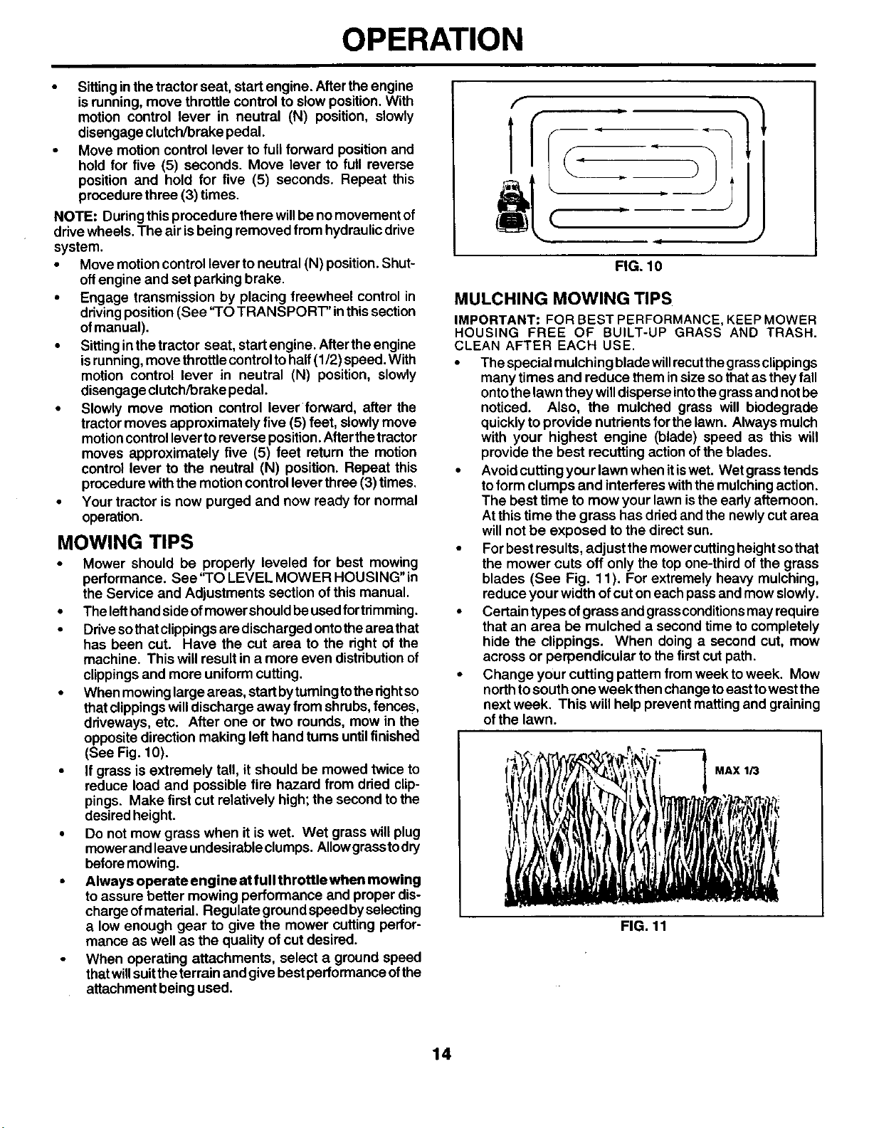
• When mowinglarge areas, startbyturningtothedght so
thatclippingswilldischarge away from shrubs,fences,
driveways, etc. After one or two rounds, mow in the
opposite direction making left hand turns until finished
(See Fig. 10).
• If grass is extremely tall, it should be mowed twice to
reduce load and possible fire hazard from dried clip-
pings. Make first cut relatively high; the second to the
desired height.
• Do not mow grass when it is wet. Wet grass will plug
mower and leave undesirableclumps. AIIowgrasstodry
before mowing.
• Always operate engine at full throttle when mowing
toassure better mowing performance and proper dis-
chargeofmaterial. Regulate ground speed byselecting
a low enough gear to give the mower cutting perfor-
mance as well as the quality of cut desired.
When operating attachments, select a ground speed
thatwillsuitthe terrain and give bestperformance ofthe
attachment being used.
J
FIG. 10
MULCHING MOWING TIPS
IMPORTANT: FOR BEST PERFORMANCE, KEEP MOWER
HOUSING FREE OF BUILT-UP GRASS AND TRASH.
CLEAN AFTER EACH USE.
• The special mulching bladewillrecutthegrassclippings
many times and reduce them insize sothat as they fall
ontothe lawn they willdisperse intothe grassand notbe
noticed. Also, the mulched grass will biodegrade
quicklyto provide nutrients forthe lawn. Always mulch
with your highest engine (blade) speed as this will
provide the best recutting actionofthe blades.
• Avoid cutting your lawn when itiswet. Wet grass tends
toform clumps and interferes withthe mulchingaction.
The best time to mow your lawn isthe early afternoon.
At this time the grass has dded and the newly cut area
will not be exposed to the direct sun.
• Forbest results, adjust themower cuttingheightsothat
the mower cuts off only the top one-third of the grass
blades (See Fig. 11). For extremely heavy mulching,
reduce your width ofcut on each passand mow slowly.
• Certain types ofgrass and grassconditionsmay require
that an area be mulched a second time to completely
hide the clippings. When doing a second cut, mow
across or perpendicular to the firstcut path.
• Change your cutting pattern from week to week. Mow
north to south one week then change toeast towest the
next week. This will help prevent matting and graining
of the lawn.
MAX 1/3
FIG. 11
14
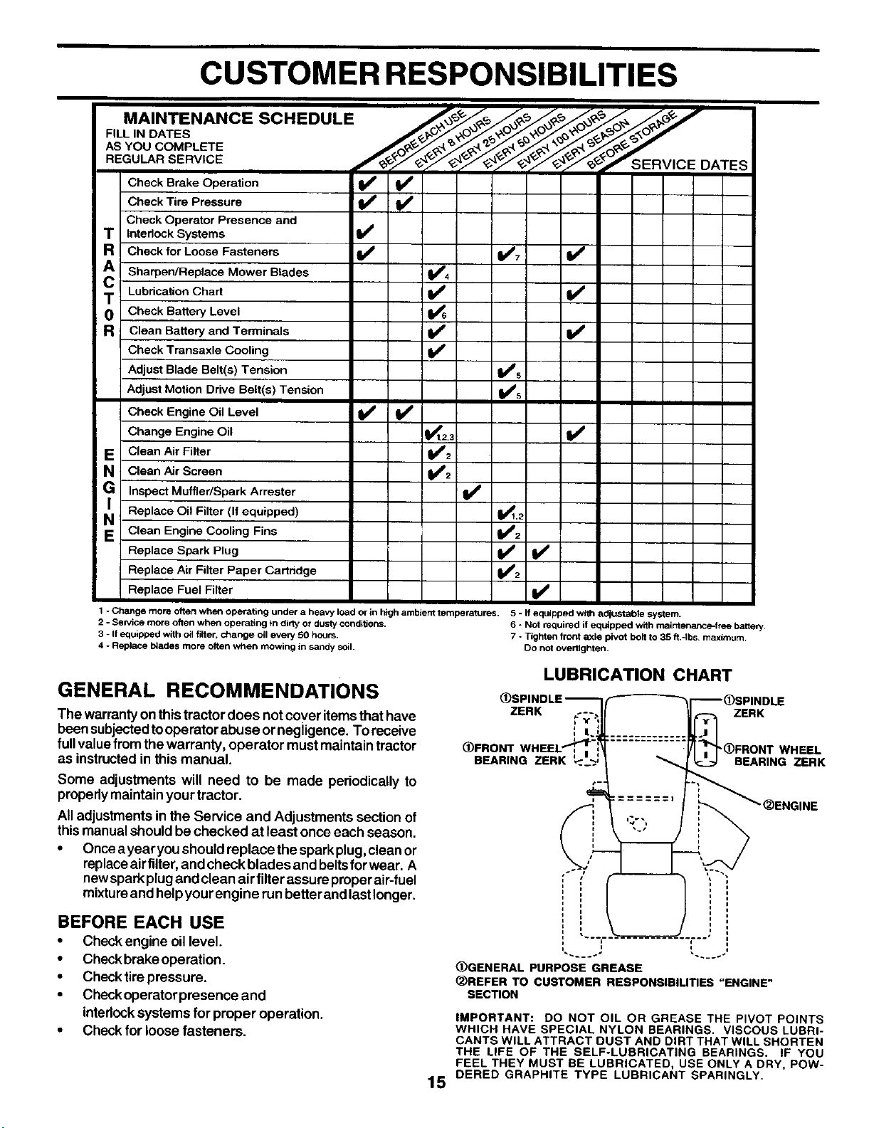
CUSTOMER RESPONSIBILITIES
F,LL,.OA ES --
AS YOU COMPLETE
SERVICE _ _7"9"_/_ &'_'_-'/_-__-'_-_-_'_--_"_'/_'07--"-- ........
REGULAR
_>'e-_:/¢'_/e-qy_'7 S ER VIC E DATES
Check Brake Operation
Check Tire Pressure _
Check Operator Presence and
T Interlock Systems V'
R Checkfor LooseFasteners Ii_ 1_7 I_
A Sharpen/Replace Mower Blades _4
T Lubrication Chart V'
0 Check Battery Level
R Clean Battery and Terminals _V' I_
Check Transaxle Cooling
Adjust Blade Belt(s) Tension VP5
Adjust Motion Drive Belt(s) Tension i_#'s
Check Engine Oil Level _
Change Engine Oil _1,2,3
E CleanAirFilter _;
N Clean Air Screen
G Inspect Muffler/Spark Arrester V _
Replace Oil Filter (If equipped) 1_.2
N Clean Engine C°°ling Fins _i
Replace Spark Plug
Replace Air Filter Paper Cartridge
Replace Fuel Filter I_
1 - Change more often when operating under a heavy load or in high ambient temperatures. 5 - If equipped with adjustable system.
2 - Service more often when operating in dirty or dusty conditions. 6 - Not required if equipped with maintenance=free batte_.
3 - If equipped with o41filter, change oil eve_ 50 hours. 7 - Tighten front =_xlepivot bolt to 35 ft.4bs, maximum.
4 - Replace b_edes more often when mowing in sandy soil. DO not overtighten.
GENERAL RECOMMENDATIONS
The warrantyon thistractor does not cover itemsthat have
been subjectedtooperator abuse ornegiigence. To receive
full value from the warranty, operator must maintain tractor
as instructedin this manual.
Some adjustments will need to be made periodically to
properlymaintain your tractor.
All adjustments in the Service and Adjustments section of
thismanual should be checked at least once each season.
• Oncea yearyou should replace the spark plug,clean or
replaceairfilter, and check blades and beltsfor wear. A
newsparkplug and clean air filterassure properair-fuel
mixtureand helpyour engine run betterand lastlonger.
BEFORE EACH USE
• Check engine oillevel.
• Checkbrake operation.
• Check tire pressure.
• Check operator presence and
interlocksystems for proper operation.
• Check for loose fasteners.
LUBRICATION CHART
ZERK ZERK
BEARING ZERK
"_FRONT WHEEL
BEARING ZERK
15
I
(!)GENERAL PURPOSE GREASE
_)REFER TO CUSTOMER RESPONSIBILITIES "ENGINE"
SECTION
IMPORTANT: DO NOT OIL OR GREASE THE PIVOT POINTS
WHICH HAVE SPECIAL NYLON BEARINGS. VISCOUS LUBRI-
CANTS WILL ATTRACT DUST AND DIRT THAT WILL SHORTEN
THE LIFE OF THE SELF-LUBRICATING BEARINGS. IF YOU
FEEL THEY MUST BE LUBRICATED, USE ONLY A DRY, POW-
DERED GRAPHITE TYPE LUBRICANT SPARINGLY.

CUSTOMER RESPONSIBILITIES
MANDREL
ASSEMBLY
TRACTOR
Always observe safety rules when performing any mainte-
nance.
BRAKE OPERATION
Iftractor requires more than six(6) feet stoppingdistance at
high speed in highest gear, then brake must be adjusted.
(See "TO ADJUST BRAKE" inthe Service and Adjustments
section of this manual).
TIRES
• Maintain properairpressure inalltires(See"PRODUCT
SPECIFICATIONS" section ofthis manual).
• Keep tires free of gasoline, oil, orinsect controlchemi-
cals which can harm rubber,
• Avoid stumps, stones, deep ruts, sharp objects and
other hazards that may cause tire damage.
NOTE: To seal tire punctures and prevent flat tires due to
slow leaks, tire sealant may be pumhased from your local
parts dealer. Tire sealant also prevents tire dry rot and
corrosion.
OPERATOR PRESENCE SYSTEM
Be sure operator presence and interlocksystems are work-
ingproperly. Ifyourtractor does notfunction as described,
repair the problem immediately.
• The engine should not start unless the clutch/brake
pedal isfullydepressed and attachement clutchcontrol
is in the disengaged position.
• When the engine isrunning,any attemptbytheoperator
to leave the seat without first settingthe parking brake
should shut offthe engine.
• When the engine isrunningandtheattachment clutchis
engaged, any attempt bythe operatorto leave theseat
should shut off the engine.
• The attachment clutchshouldnever operate unlessthe
operator is in the seat.
BLADE CARE
Forbest resultsmower bladesmustbe keptsharp. Replace
bent or damaged blades.
BLADE REMOVAL (See Fig. 12)
• Raise mower to highest position to allow access to
blades.
• Remove hex bolt, lockwasher and flatwasher securing
blade.
• Install new or resharpened blade withtrailing edge up
towards deck as shown.
IMPORTANT: TO ENSURE PROPER ASSEMBLY, CENTER
HOLE IN BLADE MUST ALIGN WITH STAR ON MANDREL
ASSEMBLY.
• Reassemble hex bolt, lock washer and flat washer in
exact order as shown.
• Tighten bolt securely (27-35 Ft. Lbs. torque).
IMPORTANT: BLADE BOLT IS GRADE 8 HEAT TREATED.
TRAILING
EDGE UP
BLADE
CENTER
HOLE
LOCK WASHER
STAR
FLAT WASHER
HEX BOLT (GRADE
8)*
*A GRADE 8 HEAT TREATED BOLT CAN BE
IDENTIFIED BY SIX LINES ON THE BOLT HEAD.
FIG. 12
TO SHARPEN BLADE (See Fig. 13)
NOTE: We do not recommend sharpening blade - butifyou
do, be sure the blade is balanced.
Care should be taken to keep the blade balanced. An
unbalanced bladewillcause excessive vibration and even-
tual damage tomower and engine.
• The blade can be sharpened with a file or on a grinding
wheel. Do not attemptto sharpen while on the mower.
• To check blade balance, you will need a 5/8" diameter
steel bolt, pin, ora cone balancer. (When using a cone
balance r,follow theinstructionssuppliedwithbalancer).
NOTE: Do not usea nailfor balancing blade. The lobes of
the center hole may appear to be centered, but are not.
• Slide blade on toan unthreaded portion ofthe steel bolt
orpin and holdthe boltorpinparallel with the ground. If
blade is balanced, it should remain in a horizontal
position. If either end of the blade moves downward,
sharpen the heavy end until the blade is balanced.
CENTER HOLE
5/8" BOLT
OR
BLADE
FIG. 13
16

CUSTOMER RESPONSIBILITIES
BATTERY SAEVISCOSITYGRADES
Your tractor has a battery charging system which is suffi-
cient for normal use. However, periodic charging of the
battery with an automotive charger willextend itslife.
• Keep battery and terminals clean.
• Keep battery boltstight.
• Keep small vent holesopen.
• Recharge at 6-10 amperes for 1 hour.
NOTE: The original equipment battery on your tractor is
maintenance free. Do notattempttoopen orremove caps or
covers. Adding or checking level of electrolyte is not
necessary.
TO CLEAN BAI-FERY AND TERMINALS
Corrosion and dirt onthe battery and terminals can cause the
battery to "leak" power.
• Open battery box door.
• Disconnect BLACK battery cable first then RED battery
cable and remove battery from tractor.
• Rinse the battery with plain water and dry.
• Clean terminals and battery cable ends with wire brush
until bright.
• Coat terminals with grease or petroleum jelly.
• Reinstall battery (See "CONNECT BATTERY" in the
Assembly section of this manual).
V-BELTS
Check V-belts for deterioration and wear after 1O0hours of
operation and replace if necessary. The belts are not
adjustable. Replace belts if they begin to slip from wear.
TRANSAXLE COOLING
The transmission fan and cooling fins should be kept clean
to assure proper cooling.
Do not attempt to clean fan or transmission while engine is
running or while the transmission is hot. To prevent possible
damage to seals, do not use high pressure water or steam
to clean transaxle.
• Inspect cooling faRto be sure fan blades are intact and
clean.
• Inspect cooling fins for dirt, grass clippings and other
materials. To prevent damage to seals, do not use
compressed airorhigh pressure sprayer toclean cooling
fins.
TRANSAXLE PUMP FLUID
The transaxle was sealed at the factory and fluid mainte-
nance isnot requiredfor the lifeofthetransaxle. Should the
transaxie ever leakorrequireservicing,contactyournearest
authorized servicecenter/department.
ENGINE
LUBRICATION
Only use high quality detergent oil rated with API service
classification SF, SG, or SH. Select the oil'sSAE viscosity
grade according toyourexpected operating temperature.
.20o 0_ 60 °
"30° -20_ -10° 0_ 10° 20 ° 30 ° 40"
TEMPERATURE RANGE ANTICIPATED BEFORE NEXT OIL CHANGE
FIG. 14
NOTE: Although multi-viscosity oils (5W30, 10W30 etc.)
improve startingin cold weather, these multi-viscosity oils
willresult in increased oil consumption when used above
32°F. Check yourengine oillevel more frequently to avoid
possibleengine damage from running low on oil.
Change the oilafter every 50 hours of operation or at least
once a year ifthe tractor is not used for 50 hours in one year.
Check the crankcase oillevel before starting the engine and
after each eight (8) hours of operation. Tighten oilfill cap/
dipstick securely each time you check the oil level.
TO CHANGE ENGINE OIL (See Figs. 14 and 15)
Determine temperature range expected before oil change.
All oil must meet API service classification SF, SG or SH.
• Be sure tractor ison level surface.
• Oil will drain more freely when warm.
• Catch oil in a suitable container.
• Remove oil fill cap/dipstick. Be careful not to allow dirt
to enter the engine when changing oil.
• Remove drain plug.
• After oil has drained completely, replace oil drain plug
and tighten securely.
• Refill engine with oilthrough oil fill dipstick tube. Pour
slowly. Do not overfill. For approximate capacity see
"PRODUCT SPECIFICATIONS" sectionof this manual.
• Use gauge on oil fill cap/dipstick for checking level. Be
sure dipstick cap is tightened securely for accurate
reading. Keep oil at "FULL" line on dipstick.
OIL FILL
CAP/DIPSTICK
DRAIN PLUG
FIG. 15
ENGINE OIL FILTER
Replace the engine oilfilter every season or every otheroil
change ifthetractorisused more than I O0hours inone year.
CLEAN AIR SCREEN (See Fig. 16)
Air screen must be kept free of dirt and chaff to prevent
engine damage fromoverheating. Clean witha wire brushor
compressed airtoremovedirtand stubbom driedgum fibers.
17

CUSTOMER RESPONSIBILITIES
ENGINE COOLING FINS (See Fig. 16)
Remove any dust, dirt or oil from engine cooling fins to
preventengine damage from overheating.
• Remove oilfill cap/dipstick.
• Remove haxbolts from blower housing and lifthousing
offengine.
• Cover oiltillopening to prevent entry of dirt.
• Use compressed air or stiff bdstle brush to thoroughly
clean engine cooling fins.
• To reassemble, reverse aboveprocedure.
HEX BLOWER HOUSING
BOLTS t HE](
_ BOLTS
DILL FILL/
DIPSTICK
ENGINE COOLING FINS,
SPARK
PLUG
FIG. 16
AIR FILTER (See Fig. 17)
Your engine willnot runproperly using adirtyairfilter. Clean
the foam pre-cleaner after every 25 hours of operation or
every season. Service paper cartddge every 100 hours of
operation or every season, whichever occurs first.
Service air cleaner more often under dusty conditions.
• Remove knob(s) and cover.
TO SERVICE PRE-CLEANER
• Slide foam pre-cleaner offcartridge.
• Wash itin liquid detergent and water.
• Squeeze itdry in a clean cloth.
• Saturate itinengine oil. Wrap itinclean,absorbent cloth
and squeeze to remove excess oil.
• Ifvery dirtyor damaged, replace pre-cleaner.
• Reinstall pre-cleaner over cartridge.
• Reinstall cover and secure with knob(s).
TO SERVICE CARTRIDGE
• Remove cartridge nut.
• Carefully remove cartridge toprevent debrisfromenter-
ing carburetor. Clean base carefully to prevent debris
fromenteringcarburetor.
• Clean cartridge bytapping gentlyon flatsurface. Ifvery
dirtyordamaged, replace cartridge.
• Reinstall cartddge, nut, precleaner, cover and secure
with knob(s).
IMPORTANT: PETROLEUM SOLVENTS, SUCH AS
KEROSENE, ARE NOT TO BE USED TO CLEAN THE
CARTRIDGE. THEY MAY CAUSE DETERIORATION OF
THE CARTRIDGE. DO NOT OIL CARTRIDGE. DO NOT
USE PRESSURIZED AIR TO CLEAN OR DRY CARTRIDGE. 18
COVER
KNOB --
CARTRIDGE
NUT
PAPER
CARTRIDGE
FOAM
PRE-CLEANER
FIG. 17
MUFFLER
Inspect and replace corroded mufflerand spark arrester (if
equipped) as itcould create a fire hazard and/or damage,
SPARK PLUGS
Replace spark plugs at the beginning, of each mowing
season or after every 100 hours of operation, whichever
occurs first. Spark plug type and gap settingare shown in
"PRODUCT SPECIFICATIONS" sectionofthis manual.
IN-LINE FUEL FILTER (See Fig. 18)
The fuel filter should be replaced once each season. Iffuel
filter becomes clogged, obstructingfuel flow tocarburetor,
rep(acementis required.
• With engine cool, remove filter and plug fuel line sec-
tions.
• Place new fuel tilter in position in fuel line with arrow
pointingtowards carburetor.
• Be sure there are no fuel line leaks and clamps are
properly positioned.
• Immediately wipe up any spilledgasoline.
CLAMP
CLAMP
FUEL
FILTER
FIG. 18
CLEANING
• Clean engine, battery, seat, finish, etc. of all foreign
matter.
• Keep finished surfaces and wheels free ofall gasoline,
oil, etc.
• Protect painted surfaces with automotive type wax.
We do not recommend using a garden hose to clean your
tractor unless the electrical system, muffler, air tilter and
carburetor are covered to keep water out. Water in engine
can result in a shortened engine life.
SERVICE AND ADJUSTMENTS
&
CAUTION: BEFORE PERFORMING ANY SERVICE OR ADJUSTMENTS:
Depress clutch/brake pedal fully and set parking brake.
Place motion control lever in neutral (N) position.
• Place attachment clutch in "DISENGAGED" position.
• Turn ignition key "OFF" and remove key.
• Make sure the blades and all moving parts have completely stopped.
• Disconnect spark plug wire from spark plug and place wire where it cannot come in contact
with plug.
TRACTOR
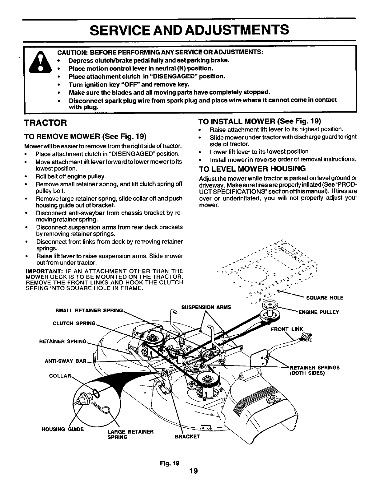
TO REMOVE MOWER (See Fig. 19)
Mowerwillbeeasier to remove from the rightside oftractor.
• Place attachment clutch in "DISENGAGED" position.
• Move attachment liftlever forward to lowermower toits
lowest position.
• Roll belt offengine pulley.
• Remove small retainer spring, and liftclutchspring off
pulley bolt.
• Remove large retainer spring, slidecollar offand push
housing guide out of bracket.
• Disconnect anti-sway'oar from chassis bracket by re-
movingretainer spring.
• Disconnect suspension arms from rear deck brackets
byremoving retainer springs.
• Disconnect front linksfrom deck by removing retainer
springs.
• Raise liftlever to raise suspension arms. Slide mower
out from under tractor.
IMPORTANT: IF AN ATTACHMENT OTHER THAN THE
MOWER DECK IS TO BE MOUNTED ON THE TRACTOR,
REMOVE THE FRONT LINKS AND HOOK THE CLUTCH
SPRING INTO SQUARE HOLE IN FRAME.
SMALL RETAINER SPRING,
TO INSTALL MOWER (See Fig. 19)
• Raise attachment lift lever to its highest position.
• Slide mower under tractor with dischargeguard toright
side of tractor.
• Lower lift lever to its lowest position.
• Install mower in reverse order of removal instructions.
TO LEVEL MOWER HOUSING
Adjust the mower while tractor is parked on level groundor
driveway. Make suretires are properlyinflated(See"PROD-
UCT SPECIFICATIONS" section ofthismanual). Iftiresare
over or underinflated, you will not propedy adjust your
mower.
"_ J-_ _ SQUARE HOLE
SUSPENSION ARMS
PULLEY
CLUTCH
FRONT LINK
RETAINER
ANTI-SWAY
COLLAR_
SPRINGS
(BOTH SIDES)
HOUSING GUIDE
LARGE RETAINER
SPRING
BRACKET
Fig. 19
19
SERVICE AND ADJUSTMENTS
SIDE-TO-SIDE ADJUSTMENT (See Figs. 20 and 21 )
• Raise mower to itshighest position.
• Atthe midpoint ofbothsides ofmower, measure height
from bottom edge ofmower toground. Distance"A" on
both sides of mower should be the same or within 1/4"
of each other.
• If adjustment is necessary, make adjustment on one
side of mower only.
• To raise one side of mower, tighten lift linkadjustment
nut on that side.
• To lower one side ofmower, loosen liftlink adjustment
nut on that side.
NOTE: Three full turnsof adjustment nutwillchange mower
height about 1/8".
Recheck measurements after adjusting.
BOTTOM EDGE BOTTOM EDGE
OF MOWER _ _ _OF MOWER
G.OU.DL..ET
FIG. 20
LIFT L_
FIG. 21
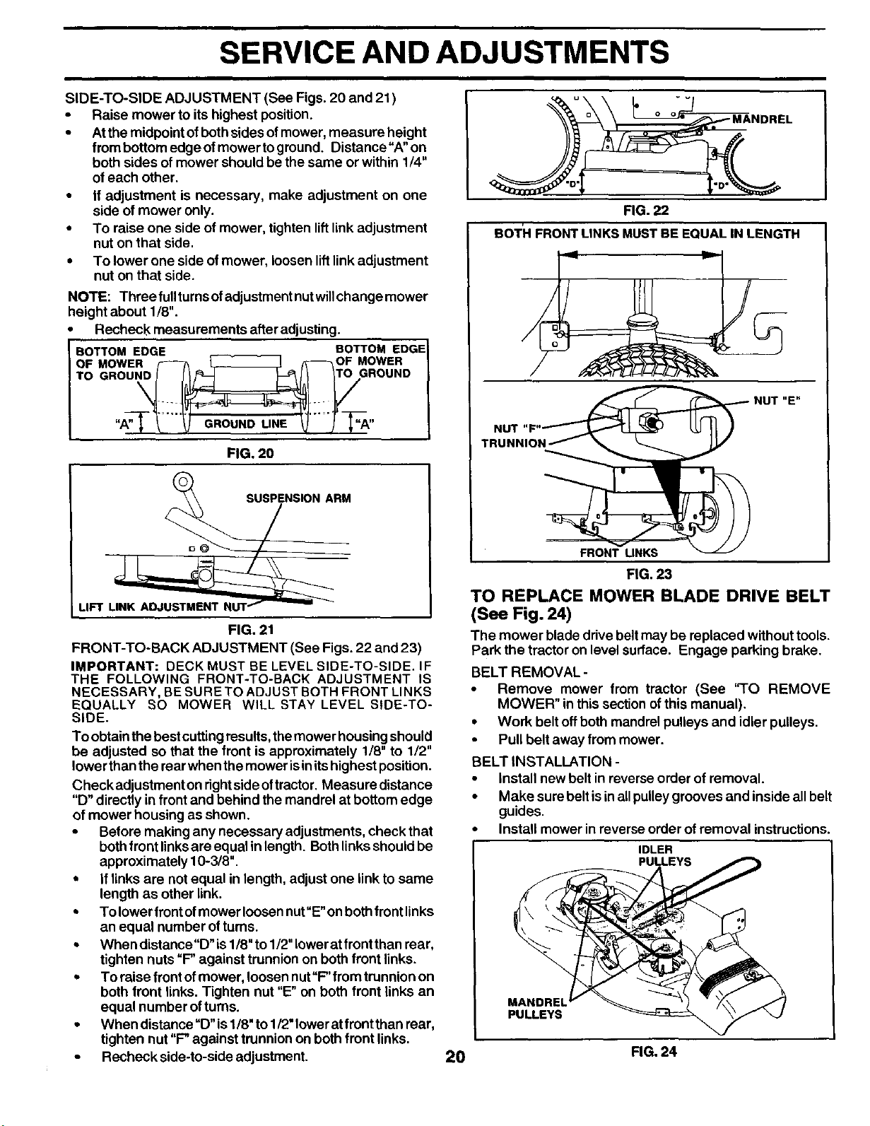
FRONT-TO-BACK ADJUSTMENT (See Figs. 22 and 23)
IMPORTANT: DECK MUST BE LEVEL SIDE-TO-SIDE. IF
THE FOLLOWING FRONT-TO-BACK ADJUSTMENT IS
NECESSARY, BE SURE TO ADJUST BOTH FRONT LINKS
EQUALLY SO MOWER WILL STAY LEVEL SIDE-TO-
SIDE.
To obtainthe best cuttingresults,the mower housing should
be adjusted so that the front is approximately 1/8" to 1/2"
lower thanthe rearwhen themower isinitshighest position.
Checkadjustment on dghtsideoftractor. Measure distance
"D" directly in frontand behind the mandrel at bottom edge
of mower housing as shown.
• Before making any necessary adjustments, check that
bothfront linksare equal inlength. Bothlinksshould be
approximately 10-3/8".
• If links are not equal in length, adjust one linkto same
length as other link.
• To lower front of mower loosen nut "E"on both front links
an equal number of turns.
• When distance"D" is 1/8" to 1/2" lower at front than rear,
tighten nuts "F" against trunnion on both front links.
• To raise front ofmower, loosen nut"F' from trunnionon
both front links. Tighten nut "E" on both front links an
equal number ofturns.
• When distance"D" is1/8"to 1/2"loweratfront than rear,
tighten nut "F" against trunnion onboth front links.
• Recheck side-to-side adjustment.
FIG. 22
BOTH FRONT LINKS MUSTBE EQUAL IN LENGTH
.u. .OT"E"
FIG. 23
TO REPLACE MOWER BLADE DRIVE BELT
(See Fig. 24)
The mower blade drive belt may be replaced without tools.
Park the tractor on level surface. Engage parking brake.
BELT REMOVAL -
• Remove mower from tractor (See '%0 REMOVE
MOWER" in this section of this manual).
• Work belt off both mandrel pulleys and idler pulleys.
• Pull belt away from mower.
BELT INSTALLATION -
• install new belt in reverse order of removal.
• Make sure belt is in aUpulley grooves and inside all belt
guides.
• install mower in reverse order of removal instructions.
IDLER
__PULLEYS
PULLEYS _ ,_ "_/
FIG, 24
2O
SERVICE AND ADJUSTMENTS
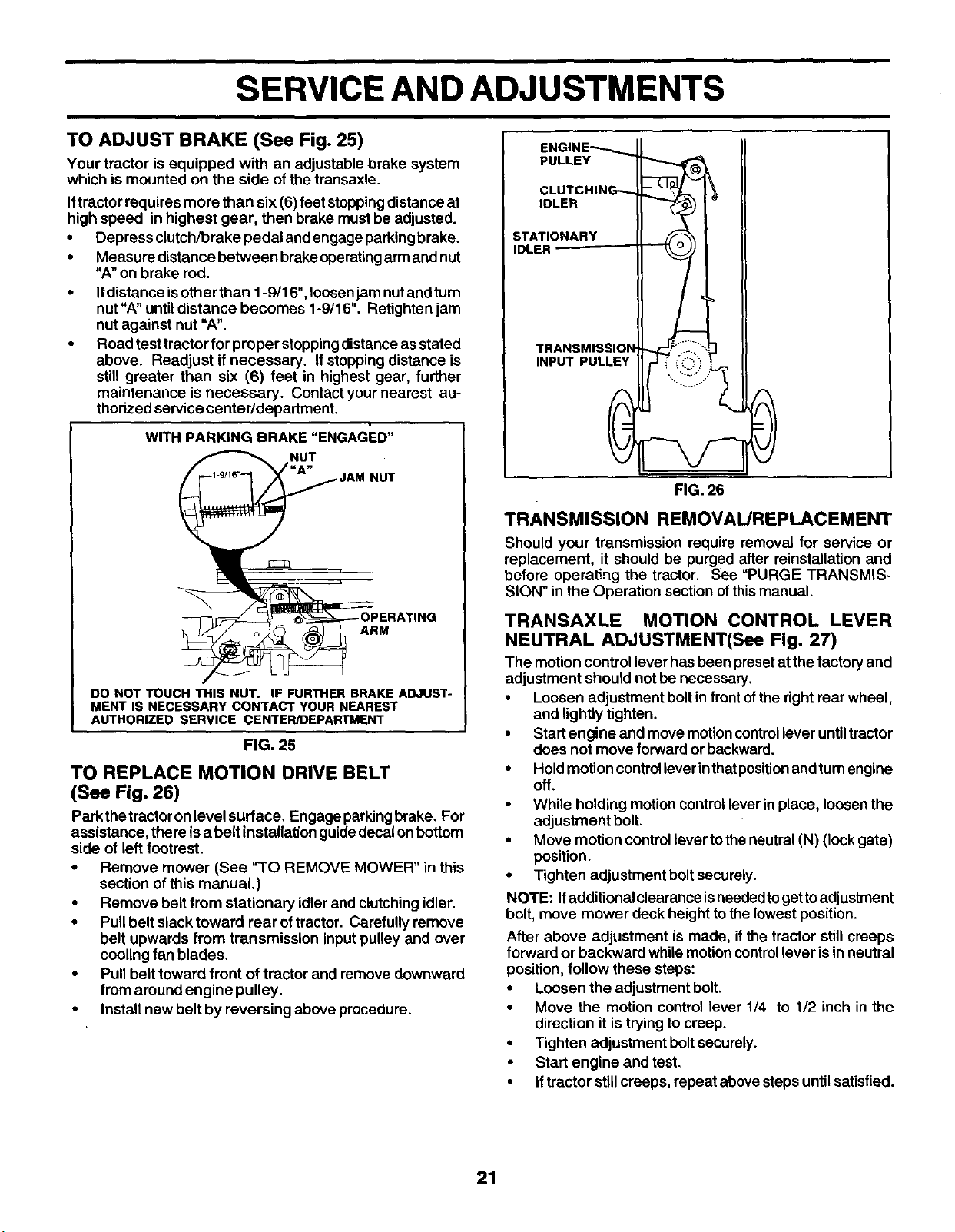
TO ADJUST BRAKE (See Fig. 25)
Your tractor is equipped with an adjustable brake system
which is mounted on the side of the transaxle.
If tractor requires more than six (6) feet stoppingdistanceat
high speed in highest gear, then brake must be adjusted.
• Depress clutch/brake pedal and engage parkingbrake.
• Measure distance between brake operatingarm and nut
"A" on brake rod.
• Ifdistance isother than 1-9/16", loosenjam nutand turn
nut"A" until distance becomes 1-9/16". Retighten jam
nut against nut "A".
Road test tractor for proper stoppingdistanceas stated
above. Readjust if necessary. Ifstopping distance is
still greater than six (6) feet in highest gear, further
maintenance is necessary. Contactyour nearest au-
thorized service center/department.
WITH PARKING BRAKE "ENGAGED"
NUT
ARM
DO NOT TOUCH THIS NUT. IF FURTHER BRAKE ADJUST-
MENT IS NECESSARY CONTACT YOUR NEAREST
AUTHOR_ED SERVICE CENTER/DEPARTMENT
FIG. 25
TO REPLACE MOTION DRIVE BELT
(See Fig. 26)
Parkthetractoronlevelsurface. Engageparkingbrake. For
assistance, there isa belt installationguide decal onbottom
side of left footrest.
• Remove mower (See "TO REMOVE MOWER" in this
section of this manual.)
• Remove belt from stationary idler and clutching idler.
• Pullbelt slack toward rear oftractor. Carefully remove
belt upwards from transmission input pulley and over
cooling fan blades.
• Pull belt toward front of tractor and remove downward
from around engine pulley.
• Install new belt by reversing above procedure.
ENGINE_
PULLEY
CLUTCHING- _ I 1
IDLER __)1 _
INP T LE ' . .....
FIG. 26
TRANSMISSION REMOVAL/REPLACEMENT
Should your transmission require removal for service or
replacement, it should be purged after reinstallation and
before operating the tractor. See =PURGE TRANSMIS-
SION" in the Operation section ofthismanual.
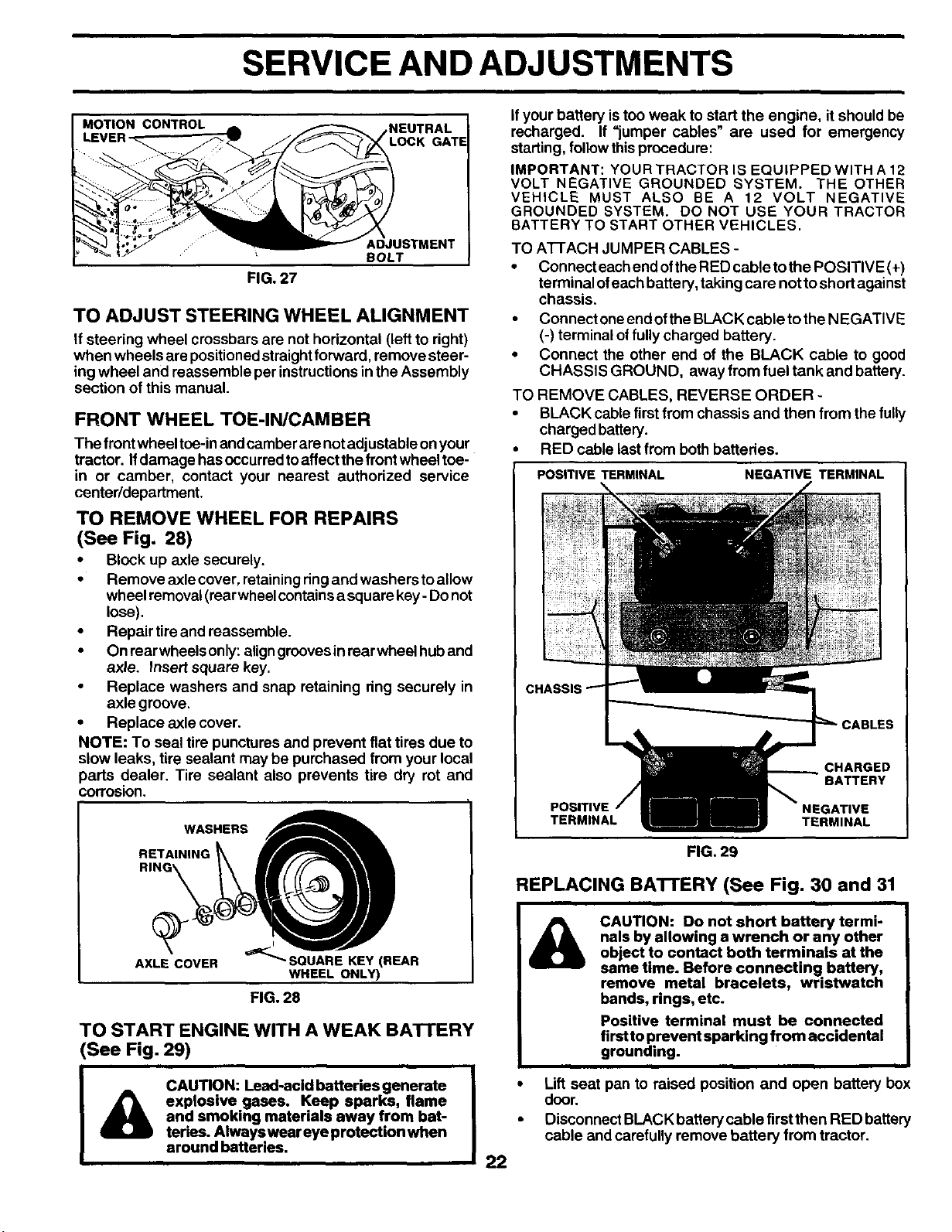
TRANSAXLE MOTION CONTROL LEVER
NEUTRAL ADJUSTMENT(See Fig. 27)
The motion controllever hasbeen presetat the factory and
adjustment should not be necessary.
• Loosen adjustment boltin frontofthe right rear wheel,
and lightly tighten.
• Startengine and move motioncontrollever untiltractor
does not move forward or backward.
• Hold motioncontrolleverinthatpositionandturnengine
oft.
• While holding motioncontrol leverin place, loosen the
adjustment bolt.
• Move motion controllever tothe neutral (N) (lock gate)
position.
• Tighten adjustment boltsecurely.
NOTE: Ifadditional clearance isneededtogettoadjustment
bolt, move mower deck height tothe lowest position.
After above adjustment is made, ifthe tractor still creeps
forward or backward while motion controllever isin neutral
position, follow these steps:
• Loosen the adjustment bolt,
• Move the motion control lever 1/4 to 1/2 inch in the
direction it is trying to creep.
• Tighten adjustment boltsecurely.
• Start engine and test.
• iftractor stillcreeps, repeat above steps untilsatisfied.
21
SERVICE AND ADJUSTMENTS
MOTION CONTROL
_NEUTRAL
LOCK GATE
ADJUSTMENT
BOLT
FIG. 27
TO ADJUST STEERING WHEEL ALIGNMENT
If steering wheel crossbars are not horizontal (left to right)
when wheels are positionedstraightforward, remove steer-
ing wheel and reassemble per instructionsin the Assembly
section of this manual.
FRONT WHEEL TOE-IN/CAMBER
The frontwheel toe-in andcamber are notadjustable on your
tractor. Ifdamage hasoccurredtoaffectthe front wheel toe-
in or camber, contact your nearest authorized service
center/department.
TO REMOVE WHEEL FOR REPAIRS
(See Fig. 28)
• Block up axle securely.
• Remove axle cover, retainingringand washers toallow
wheel removal(rearwheel containsa square key- Do not
lose).
• Repair tire and reassemble.
• On rearwheeis only:align groovesin rear wheel huband
axle. Insert square key.
Replace washers and snap retaining dng securely in
axle groove.
• Replace axle cover.
NOTE: To seal tire punctures and prevent flat tires due to
slow leaks, tire sealant may be purchased from your local
parts dealer. Tire sealant also prevents tire dry rot and
corrosion.
WASHERS
RETA,NING
,
AXLECOVER _'_SOUARE KEYINEI_R
WHEEL ONL_
FIG. 28
TO START ENGINE WITH A WEAK BATTERY
(See Fig. 29)
CAUTION: Lead-acid batteries generate
_1) explosive gases. Keep sparks, flame
and smoking materials away from bat-
teries. Always wear eye protection when
around batteries.
If your battery is too weak to start the engine, it should be
recharged. If "jumper cables" are used for emergency
starting, follow this procedure:
IMPORTANT: YOUR TRACTOR IS EQUIPPED WITH A 12
VOLT NEGATIVE GROUNDED SYSTEM. THE OTHER
VEHICLE MUST ALSO BE A 12 VOLT NEGATIVE
GROUNDED SYSTEM. DO NOT USE YOUR TRACTOR
BATTERY TO START OTHER VEHICLES.
TO A'I-I-ACH JUMPER CABLES -
• Connect each and ofthe RED cabletothe POSITIVE (+)
terminal ofeach battery, taking care not to short against
chassis.
• Connect one end of the BLACK cable to the NEGATIVE
(-) terminal of fully charged battery.
• Connect the other end of the BLACK cable to good
CHASSIS GROUND, away from fuel tank and battery.
TO REMOVE CABLES, REVERSE ORDER -
• BLACK cable first from chassis and then from the fully
charged battery.
• RED cable lastfrom both battedes.
POSITIVE TERMINAL NEGATIVE TERMINAL
22
FIG, 29
REPLACING BATI'ERY (See Fig. 30 and 31
&
CAUTION: Do not short battery termi-
nals by allowing a wrench or any other
object to contact both terminals at the
same time. Before connecting battery,
remove metal bracelets, wristwatch
bands, rings, etc.
Positive terminal must be connected
firstto prevent sparking from accidental
grounding.
• Lift seat pan to raised position and open battery box
door.
• Disconnect BLACK battery cable first then RED battery
cable and carefully remove battery from tractor.
SERVICE AND ADJUSTMENTS
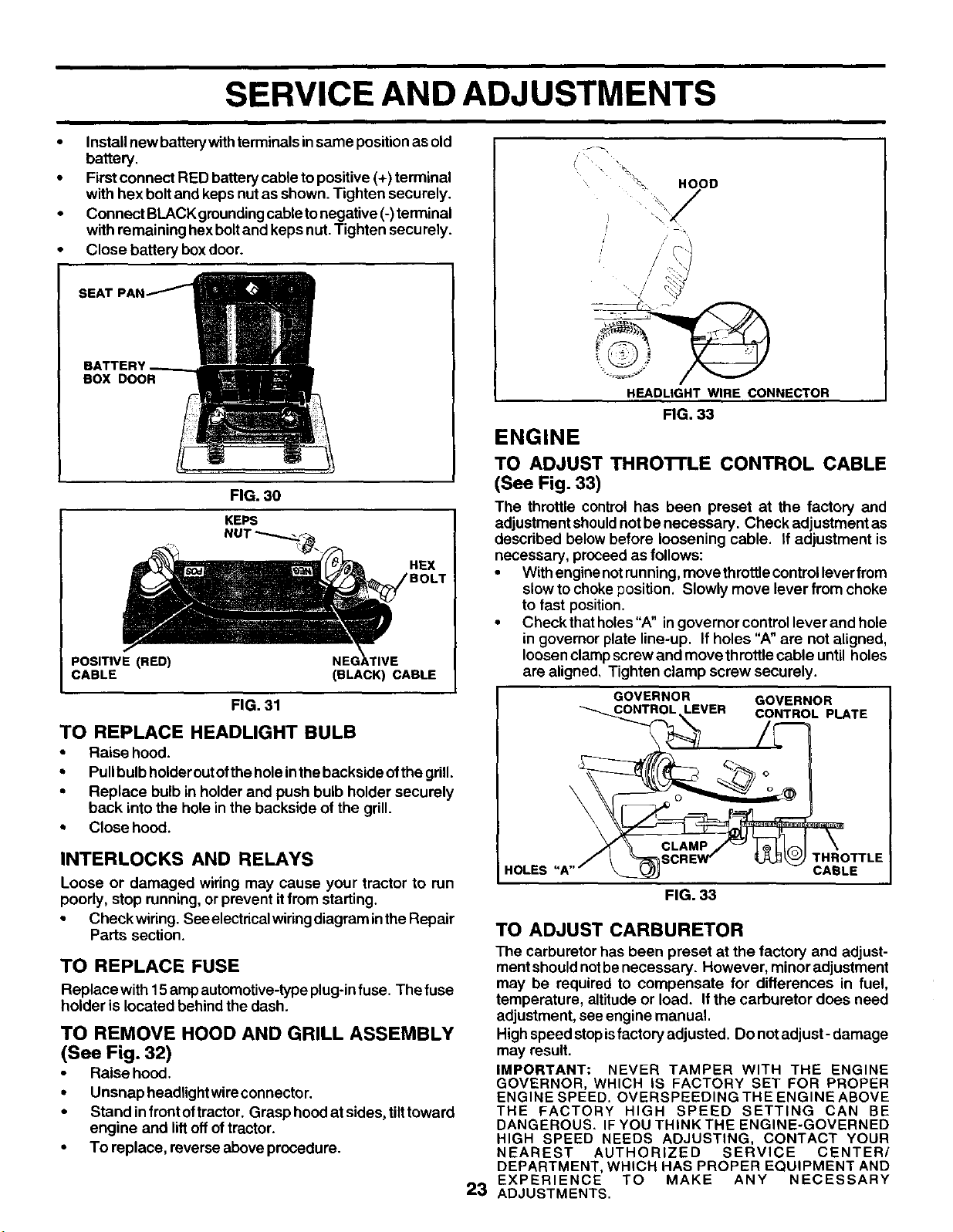
• Installnew battery withterminals insame position as old
battery.
• First connect RED battery cable to positive (+) terminal
with hex bolt and keps nut as shown. Tighten securely.
• Connect BLACK grounding cable to negative (-) terminal
with remaining hex bolt and keps nut. Tighten secu rely.
• Close battery box door.
BOX DOOR
FIG. 30
KEPS
NUT_._
HEX
POSITIVE (RED)
CABLE
(BLACK) CABLE
FIG.31
TO REPLACE HEADLIGHT BULB
• Raise hood.
• Pullbulb holderout ofthe hole inthe backside ofthe grill.
• Replace bulb in holder and push bulb holder securely
back into the holein the backside of the grill.
• Close hood.
INTERLOCKS AND RELAYS
Loose or damaged wiring may cause your tractor to run
poorly, stop running, or prevent itfrom starting.
• Checkwiring. See electrical wiring diagram in the Repair
Parts section.
TO REPLACE FUSE
Replace with 15 ampautomotive-typeplug-infuse. The fuse
holder is located behind the dash.
TO REMOVE HOOD AND GRILL ASSEMBLY
(See Fig. 32)
• Raise hood.
• Unsnap headlightwireconnector.
• Stand infront oftractor. Grasp hood at sides, tilttoward
engine and liltoff oftractor.
• To replace, reverse above procedure.
HOOD
HEADLIGHT WIRE CONNECTOR
FIG. 33
ENGINE
TO ADJUST THRO'FrLE CONTROL CABLE
(See Fig. 33)
The throttle control has been preset at the factory and
adjustment shouldnot be necessary. Check adjustment as
described below before loosening cable. If adjustment is
necessary, proceed as follows:
• With enginenotrunning,move throttlecontrollever from
slow tochoke position. Slowly move lever from choke
to fast position.
• Check thatholes"A" in governor control lever and hole
in governor plate line-up, If holes "A" are not aligned,
loosenclamp screw and move throttle cable until holes
are aligned, Tighten clamp screw securely.
GOVERNOR GOVERNOR
LEVER CONTROL PLATE
\
\
CLAMP
THROTTLE
HOLES CABLE
FIG. 33
TO ADJUST CARBURETOR
The carburetor has been preset at the factory and adjust-
ment shouldnotbe necessary. However, minor adjustment
may be required to compensate for differences in fuel,
temperature, altitude or load. Ifthe carburetor does need
adjustment, see engine manual.
Highspeod stopisfactory adjusted. Do notadjust- damage
may result.
IMPORTANT: NEVER TAMPER WITH THE ENGINE
GOVERNOR, WHICH IS FACTORY SET FOR PROPER
ENGINE SPEED. OVERSPEEDING THE ENGINE ABOVE
THE FACTORY HIGH SPEED SETTING CAN BE
DANGEROUS. IF YOU THINK THE ENGINE-GOVERNED
HIGH SPEED NEEDS ADJUSTING, CONTACT YOUR
NEAREST AUTHORIZED SERVICE CENTER/
DEPARTMENT, WHICH HAS PROPER EQUIPMENT AND
EXPERIENCE TO MAKE ANY NECESSARY
2:3 ADJUSTMENTS.
STORAGE
Immediately prepare yourtractorfor storageatthe end ofthe
season or ifthe tractor will notbe used for 30 days or more.
&
CAUTION: Never store the tractor with
gasoline in the tank inside a building
where fumes may reach an open flame
or spark. Allow the engine to cool
before storing in any enclosure.
TRACTOR
Remove mower fromtractorforwinterstorage. When mower
is to be stored for a period of time, clean it thoroughly,
remove all dirt, grease, leaves, etc, Store in a clean, dry
area.
• Clean entiretractor (See"CLEANING" inthe Customer
Responsibilities section of this manual).
• Inspect and replace belts, if necessary (See belt re-
placement instructions inthe Service and Adjustments
section of this manual).
• Lubricate as shown in the Customer Responsibilities
section ofthis manual.
• Be sure that all nuts, bolts and screws are securely
fastened. Inspect moving parts for damage, breakage
and wear. Replace ifnecessary.
• Touch up all rusted or chipped paint surfaces; sand
lightlybefore painting.
BATTERY
• Fully charge the battery for storage.
• After a pedod of time in storage, battery may require
recharging.
• TOhelpprevent corrosionand power leakage duringlong
periods of storage, battery cables should be discon-
nected and battery cleaned thoroughly (see"TO CLEAN
BATTERY ANDTERMINALS" inthe Customer Respon-
sibilities section of this manual).
• After cleaning, leave cables disconnected and place
cables where they cannot come incontact with batte_
terminals.
• If battery is removed from tractor for storage, do not
store battery directly on concrete or damp surfaces.
ENGINE
FUEL SYSTEM
IMPORTANT: IT IS IMPORTANT TO PREVENT GUM
DEPOSITS FROM FORMING IN ESSENTIAL FUEL SYSTEM
PARTS SUCH AS CARBURETOR, FUEL FILTER, FUEL
HOSE, OR TANK DURING STORAGE, ALSO,
EXPERIENCE INDICATES THAT ALCOHOL BLENDED
FUELS (CALLED GASOHOL OR USING ETHANOL OR
METHANOL) CAN ATTRACT MOISTURE WHICH LEADS
TO SEPARATION AND FORMATION OF ACIDS DURING
STORAGE. ACIDIC GAS CAN DAMAGE THE FUEL
SYSTEM OF AN ENGINE WHILE IN STORAGE.
• Drain the fuel tank.
• Start the engine and let it run until the fuel lines and
carburetor are empty.
• Never use engine or carburetor cleaner products in the
fuel tank or permanent damage may occur.
• Use fresh fuel next season.
NOTE: Fuel stabilizer is an acceptable alternative in
minimizing the formation of fuel gum deposits during stor-
age. Add stabilizer to gasoline in fuel tank or storage
container. Always follow the mix ratio found on stabilizer
container. Run engine at least 10 minutes after adding
stabilizer to allow the stabilizer to reachthe carburetor. Do
not drain the gas tank and carburetor ifusingfuel stabilizer.
ENGINE OIL
Drain oil(with engine warm) and replacewith cleanengine oil,
(See "ENGINE" inthe Customer Responsibilities section of
this manual).
CYUNDER(S)
• Remove spark plug(s).
• Pour one ounce of oil through spark plug hole(s) into
cylinder(s).
• Tum ignitionkey to"START" positionfora few seconds
to distribute oil.
• Replace with new spark plug(s).
OTHER
• Do not store gasoline from one season toanother.
• Replace your gasoline can if your can starts to rust.
Rust and/or dirt in your gasoline willcause problems.
• Ifpossible, store your tractorindoors and cover ittogive
protection from dust and dirt.
• Cover your tractor with a suitable protective cover that
does not retain moisture. Do not use plastic, Plastic
cannot breathe which allows condensationtoform and
will cause your tractor to rust,
IMPORTANT: NEVER COVER TRACTOR WHILE ENGINE
AND EXHAUST AREAS ARE STILL WARM.
24
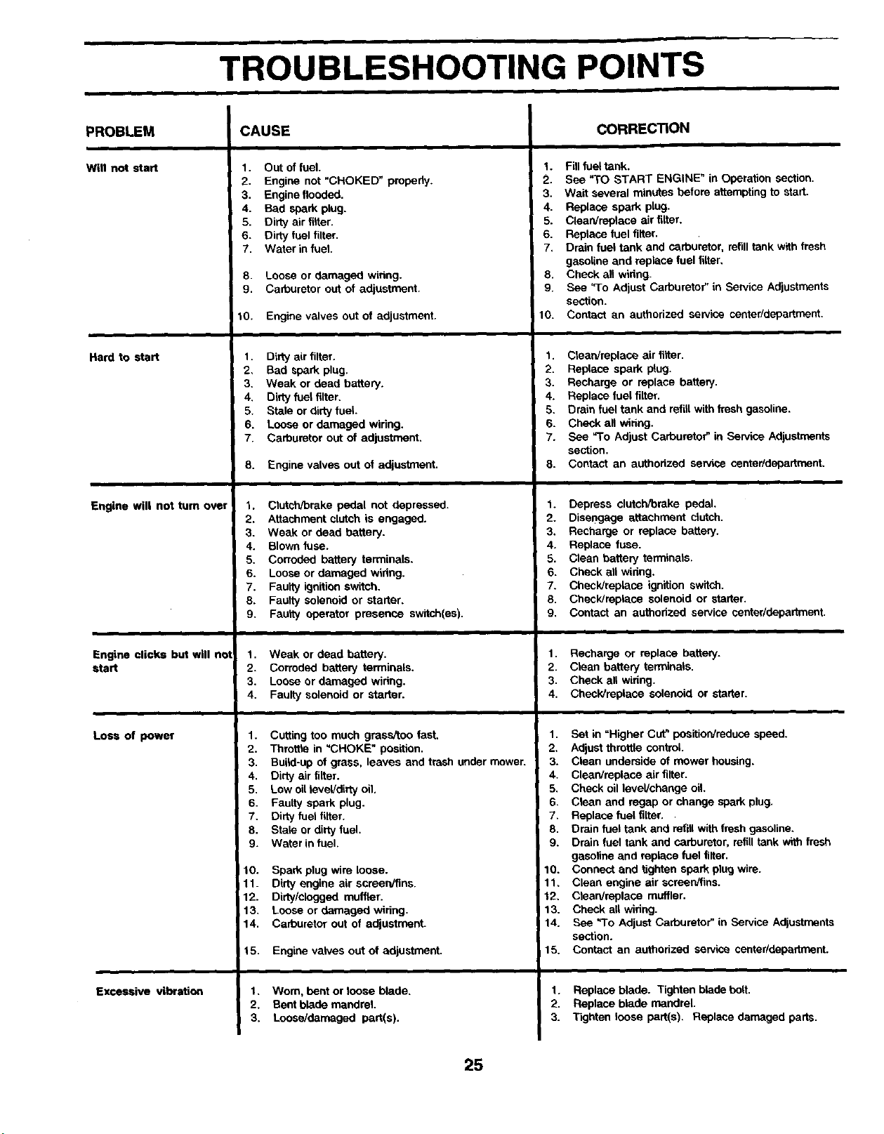
TROUBLESHOOTING POINTS
PROBLEM
Will not start
Ha_ _ _art
Engine wilt not turn over
Engine clicks but will net
start
Loss of power
Excessive vibration
CAUSE
1. Out of fuel.
2. Engine not "CHOKED" propedy.
3. Engine flooded.
4. Bad spark plug.
5. Dirty air filter.
6. Dirty fuel filter.
7. Water in fuel.
8. Loose or damaged wiring.
9. Carburetor out of adjustment.
10. Engine valves out of adjustment.
1. Dirty air tilter.
2. Bad spark plug.
3. Weak or dead battery.
4. Dirty fuel filter.
5. Stale or dirty fuel.
6. Loose or damaged widng.
7. Carburetor out of adjustment,
8. Engine valves out of adjustment.
1. Cletch/brake pedal not depressed.
2. Attachment clutch is engaged.
3. Weak or dead battery.
4. Blown fuse.
5. Corroded battery terminals.
6. Loose or damaged widng.
7. Faulty ignition switch.
8. Faulty solenoid or starter,
9. Fau_y operator presence switch(es).
1. Weak or dead battery.
2. Corroded battery terminals.
3. Loose or damaged widng.
4. Faulty solenoid or starter.
1. Cutting too much grass/too fast.
2. Throffie in "CHOKE" position.
3. Build-up of grass, leaves and trash under mower.
4. Dirty air tilter.
5. Low oil level/dirty oil.
6. Faulty spark plug.
7. Dirty fuai filter.
8. Stale or dirty fuel.
9. Water in fuel.
i 10. Spark plug wire loose.
11. Dirty engine air screen/fins.
12. Dirty/clogged muffler.
13. Loose or damaged wiring.
14. Carburetor out of adjustment.
t 5. Engine valves out of adjustment.
1, Worn, bent or loose blade.
2, Bent blade mandrel
3. Loose/damaged part(s).
CORRECTION
1. Fill fuel tank.
2. See "TO START ENGINE" in Operation section.
3. Wait several minutes before attempting to start.
4. Replace spark plug.
5. Clean/replace air filter,
6. Replace fuel filter.
7, Drain fuel tank and carburetor, refill tank with fresh
gasoline and replace fuel tilter,
8. Check all widng.
9. See =To Adjust Carburetor" in Service Adjustments
section.
10. Contact en authorized service center/department.
1. Clean/replace air tilter.
2. Replace spark plug.
3. Recharge or replace battery.
4. Replace fuel filter.
5. Drain fuel tank and reffil with fresh gasoline.
6. Check an wiring.
7. See "To Adjust Carburetor" in Service Adjustments
section.
8. Contact an authorized service center/department,
1. Depress clutch/brake pedal,
2. Disengage attachment clutch.
3. Recharge or replace battery.
4. Replace fuse.
5. Clean battery terminals.
6. Check ell widng.
7. Check/replase ignition switch.
8. Checldreplase solenoid or starter.
9. Contact an authorized service center/department.
1. Recharge or replace battery.
2. Clean battery terminals.
3. Check all widng.
4. Check/replace solenoid or starter.
1. Set in "Higher Cut" position/reduce speed.
2. Adjust throttle control
3. Clean underside of mower housing,
4. Clean/replace air filter.
5. Check oil level/change oil,
6. Clean and regal) or change spark plug.
7. Replace fuel filter,
8. Drain fuel tank and refill with fresh gasoline,
9. Drain fuel tank and carburetor, refill tank with fresh
gasoline and replace fuel tilter.
10. Connect and tighten spark plug wire.
11, Clean engine air screen/tins.
12, Clean/replace muffler.
13. Check all wiring.
14. See "To Adjust Carburetor" in Service Adjustments
section.
15. Contact an authorized service center/department.
1. Replace blade. Tighten blade bolt.
2. Replace blade mandrel.
3. Tighten loose part(s). Replace damaged parts.
25
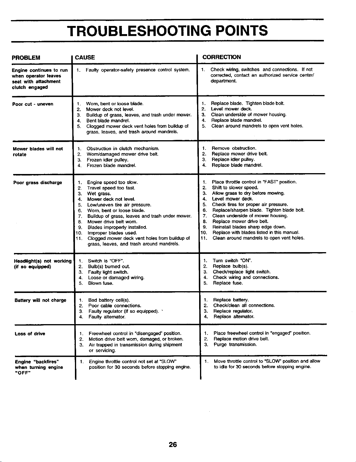
TROUBLESHOOTING POINTS
PROBLEM
Engine continues to run
when operator leaves
seat with attachment
clutch engaged
Poor cut - uneven
Mower blades will not
rotate
Poor grass discharge
Headlight(s) not working
(if so equipped)
Battery will not charge
Loss of drive
Engine "backfires"
when turning engine
"OFF"
CAUSE
1. Faulty operator-safety presence controlsystem,
1. Worn, bent or loose blade.
2. Mower deck not level.
3. Buildup of grass, leaves, and trash under mower.
4. Bent blade mandrel.
5. Clogged mower deck vent holes from buildup of
grass, leaves, and trash around mandrels.
1. Obstruction in clutch mechanism.
2. Worn/damaged mower drive belt.
3. Frozen idler pulley.
4. Frozen blade mandrel.
1. Engine speed too slow.
2. Travel speed too fast.
3. Wet grass.
4. Mower deck not level.
5. Low/uneven tire air pressure.
6. Worn. bent or loose blade.
7. Buildup of grass, leaves and trash under mower.
8. Mower drive bell worn.
9. Blades improperly installed.
10. Improper blades used.
t t. Clogged mower deck vent holes from buildup of
grass, leaves, and trash around mandrels.
t. Switch is "OFF'.
2, Bulb(s) burned out.
3. Faulty light switch,
4. Loose or damaged wiring.
5. Blown fuse.
t. Bad battery cell(s).
2. Poor cable connections.
3. Faulty regulator (if so equipped). "
4. Faulty allemator.
1. Freewheel control in "disengaged" position.
2. Motion drive belt worn. damaged, or broken.
3. Air trapped in transmission during shipment
or servicing.
1.
Engine throttle control not set at =SLOW"
position for 30 seconds before stopping engine.
CORRECTION
1. Check wiring,switches and connections. If not
corrected,contactan authorizedservice canter/
depadment.
1. Replace blade. Tighten blade bolt.
2. Level mower deck.
3. Clean underside of mower housing.
4. Replace blade mandrel.
5. Clean around mandrels to open vent holes.
1. Remove obstruction.
2. Replace mower drive belt.
3. Replace idler pulley.
4. Replace blade mandrel.
1. Place throttle control in "FAST" position.
2. Shift to slower speed.
3. Allow grass to dry before mewing.
4. Level mower deck.
5. Check tires for prober air pressure.
6. Replace/sharpen blade. Tighten blade bolt.
7. Clean underside of mower housing.
8. Replace mower drive belt.
9. Reinstall blades sharp edge down.
10. Replace with blades listed in this manual.
11. Clean around mandrels to open vent holes.
t. Turn switch "ON".
2. Replace bulb(s).
3. ChecWreplace light switch.
4. Check widng and connections.
5. Replace fuse.
1. Replace battery.
2, Check/clean all connections.
3. Replace regulator.
4. Replace allemator.
1. Place freewheel control in "engaged" position.
2. Replace motion drive belt.
3. Purge transmission.
1. Move throttle control to "SLOW" position and allow
to idle for 30 seconds before stopping engine.
26
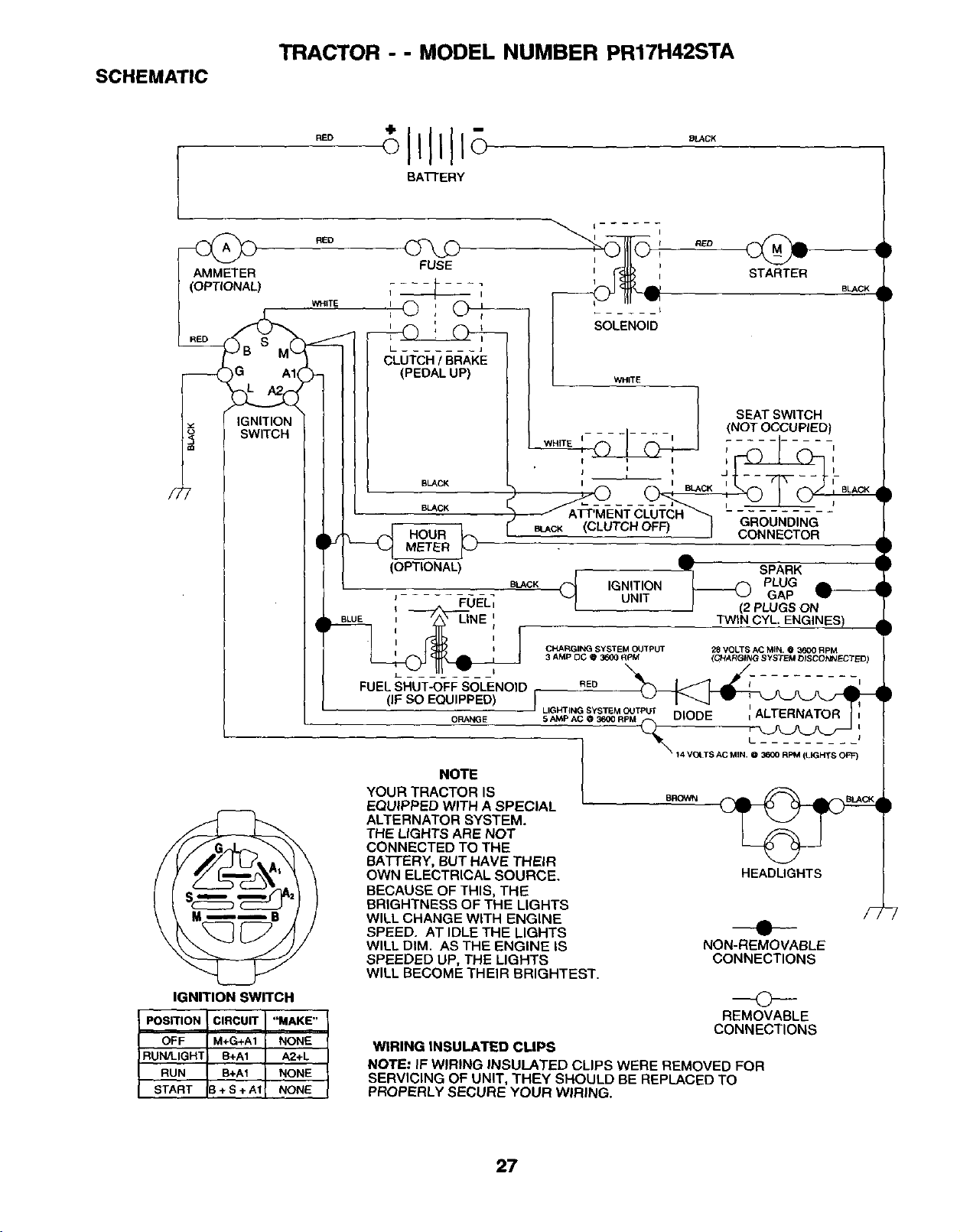
SCHEMATIC
TRACTOR - - MODEL NUMBER PR17H42STA
RED
I
RED
) WHITE
G AI(
IGNITION
SWITCH
BATrERY
FUSE
' © '
i i t
LUTCH/SBAK
(PEDAL UP)
BLACK
BLACK
___ HOURMETER
(OPTIONAL)
BUCK
BLACK
I
Q RED
STARTER
SOLENOID
WHITE
_ IWHITE I i i
j I t J
' © ,
BLACK (CLUTCH OFF)J
SEAT SWITCH
(NOT OCCUPIED
GROUNDING
CONNECTOR
: FUEL;
i I
FUEL SHUT-OFF SOLENOID
(IF SO EQUIPPED)
ORANGE
A
SPARK
(_ IGNITION _ PLUG
UNIT I '-J GAP
i (2 PLUGS ON
TWIN CYL ENGINES)
BUCK
CHARGING SYSTEM OUTPUT 28 VOLTS AC MIN. @ 3600 RPM
3 AMP OC @ 3600 RPM (CHARGI'NG SYSTEM DISCONNECTED)
RED i_
I LIGHTING SYSTEM OUTPLrI" I
5 ,_&P AC @ 3600 R
_t4 VOLTS AC MIN. @ 3600 RPM (LIGHTS OFF)
IGNITION SWITCH
POSITION CIRCUIT "MAKE"
OFF M+G+A1 NONE
RUN/LIGH3 B+A1 A2+L
RUN B+A1 NONE
START 3 + S + A1 NONE
NOTE
YOUR TRACTOR IS
EQUIPPED WITH A SPECIAL
ALTERNATOR SYSTEM.
THE LfGHTS ARE NOT
CONNECTED TO THE
BATTERY, BUT HAVE THEIR
OWN ELECTRICAL SOURCE.
BECAUSE OF THIS, THE
BRIGHTNESS OF THE LIGHTS
WILL CHANGE WITH ENGINE
SPEED. AT IDLE THE LIGHTS
WILL DIM. AS THE ENGINE IS
SPEEDED UP, THE LIGHTS
WILL BECOME THEIR BRIGHTEST.
HEADLIGHTS
NON-REMOVABLE
CONNECTIONS
0
REMOVABLE
CONNECTIONS
WIRING INSULATED CLIPS
NOTE: IF WIRING INSULATED CLIPS WERE REMOVED FOR
SERVICING OF UNIT, THEY SHOULD BE REPLACED TO
PROPERLY SECURE YOUR WIRING.
27
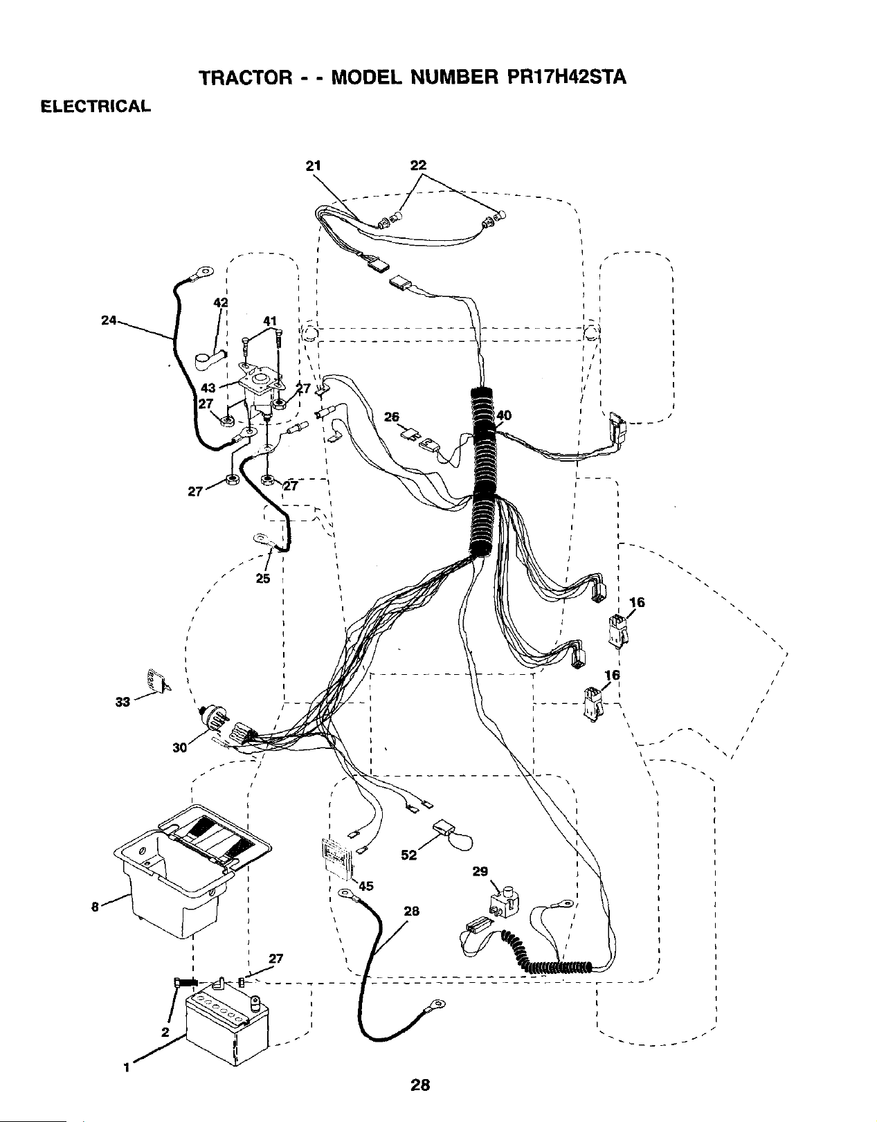
ELECTRICAL
TRACTOR - - MODEL NUMBER PR17H42STA
t
i t
i I
42
I
41
25
21 22
I
I
J
\ I
26
I /i
i / 1
it t
I
I
16
I
\
L
I
I
\ //
r --
I
I
I
I
I
I
/
/
\
//
/
/
/"
/
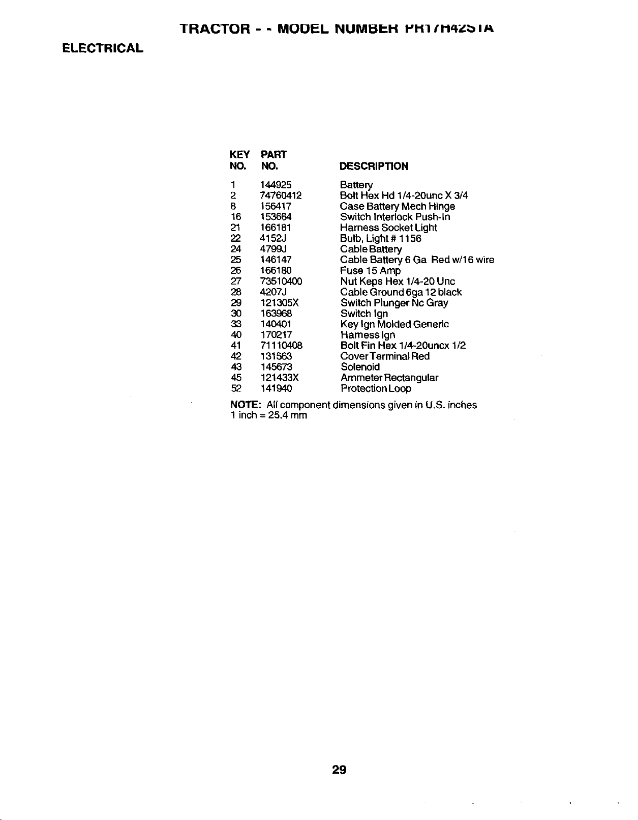
ELECTRICAL
TRACTOR - - MODEL NUMBI::H _'H]/H4Zbl_
KEY PART
NO. NO. DESCRIPTION
1 144925
2 74760412
8 156417
16 153664
21 166181
22 4152J
24 4799J
25 146147
26 16618O
27 73510400
28 4207J
29 121305X
30 163968
33 140401
40 170217
41 71110408
42 131563
43 145673
45 121433X
52 141940
Battery
Bolt Hex Hd 1/4-20unc X 3/4
Case Battery Mech Hinge
Switch Interlock Push-In
Harness Socket Light
Bulb, Light# 1156
Cable Battery
Cable Battery 6 Ga Red w/16 wire
Fuse 15 Amp
Nut Keps Hex 1/4-20 Unc
Cable Ground 6ga 12 black
Switch Plunger Nc Gray
Switch Ign
Key Ign Molded Generic
Harness Ign
Bolt Fin Hex l/4-20uncx 1/2
CoverTerminal Red
Solenoid
Ammeter Rectangular
Protection Loop
NOTE: All component dimensions given in U.S. inches
1 inch = 25.4 mm
29
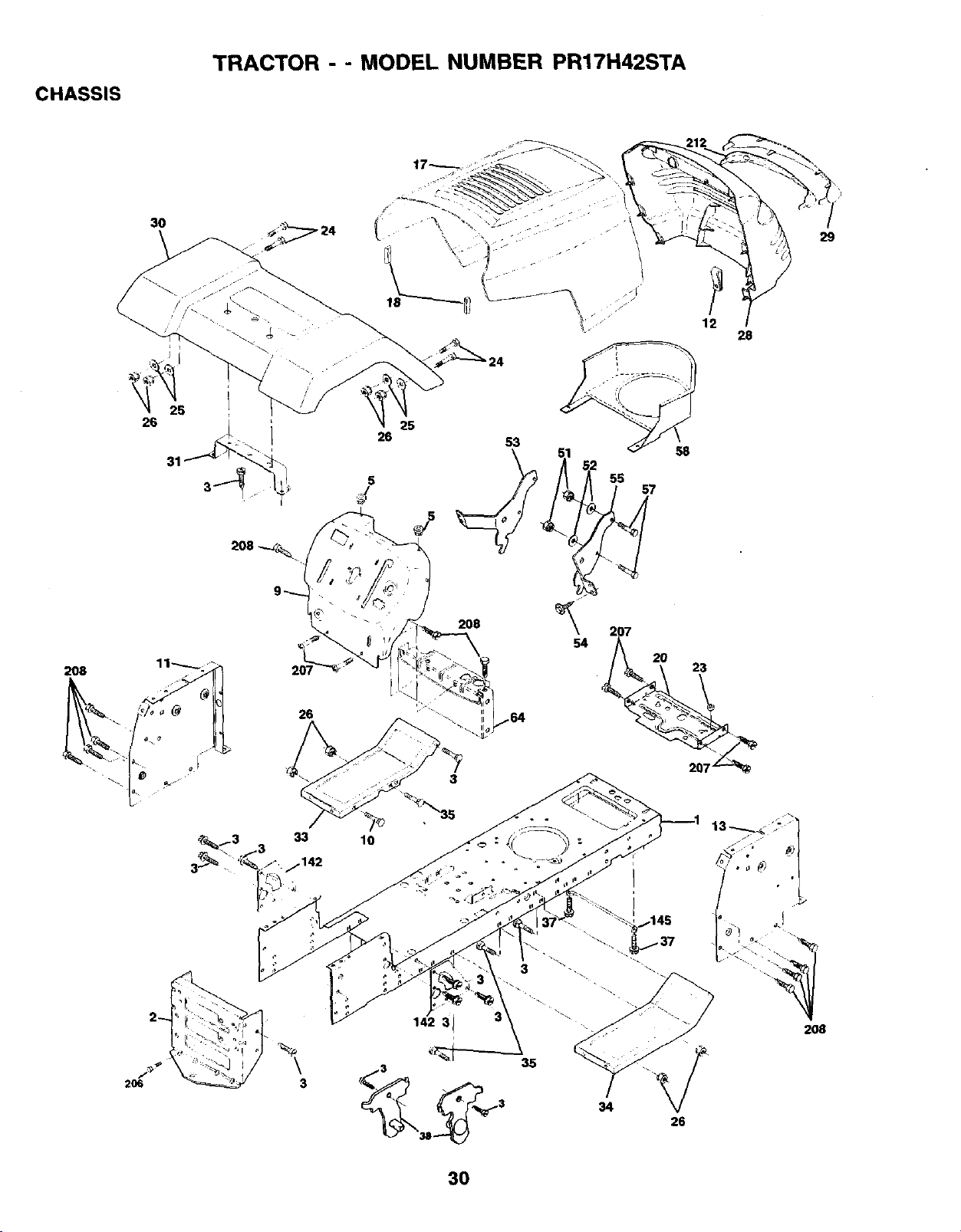
CHASSIS
TRACTOR - - MODEL NUMBER PR17H42STA
26
25
53
55
57
12
28
58
29
208
26
208
II
54
207
20 23
33
.142
\
3
lO
3
35
34
26
30

CHASSIS
TRACTOR - - MUUI'L NUMI:iI'H laH'l tH4ZtblA
KEY PART
NO. NO. DESCRIPTION
1 169830
2 169061
3 17060612
5 155272
9 168337X012
10 72140608
11 155927
12 145660
13 172108
17 159639)(428
18 126938X
20 156437
23 124028X
24 74780616
25 19131312
26 73800600
28 170474
29 170472X599
30 169468X428
31 136619
33 145244X428
34 145243X428
35 72110606
37 17490508
38 169834
51 73800400
52 19091416
53 144697
54 161464
55 144696
57 74780412
58 150127
64 154798
142 165867
145 156524
206 170165
207 17670508
208 17670608
212 156229
- - 5479J
Chassis
Draw'oar
Screw 3/8-16 X .75
Bumper Hood/Dash
Dash P/L
Bolt Carriage 3/8-16 x 1
Panel Dash Lh
ClipTinnerman
Panel Dash Rh
Hood LT/PL
BumperHood
Plate Mtg Battery Fuel Tank Fr
Bushing
Bolt Fin Hex 3/8-16 x 1 Gr 5
Washer 13/32 X 13/16 X 12 Ga
Nut Lock Hex W/Ins 3/8-16 Unc
Grille/Lens Asm
Lens LT/PL
Fender Footrest STLT Pnt
Bracket Fender
Footrest Pnt Lh
Footrest Pnt Rh
Bolt Rdhd Sht Sqnk 3/8-16 x 3/4
Screw Thdrol 6/16-18 x 1/2 TYT
Bracket Asm Pivot Mower Rear
Nut Lock Hex W/Ins 1/4-20
Washer 9/32 x 7/8 x 16 Ga.
Bracjet Gmkke Lh
Screw Hex Wshd 8-18 x 7/8
Bracket Gdlle Rh
Bolt Hex 1/4-20 x 3/4
Duct Air
Dash LowerSTLT
Plate Reinforcement STLT
Rod Pivot Chassis/Hood
BoltShoulder 5/16-18
Screw Thdrol 5/16-18 x 112
Screw Thdrol 3/8-16 x 1/2
Insert Lens Relect
Plug Button
NOTE: All component dimensions given in U.S, inches
1 inch = 25.4 mm
31

DRIVE
TRACTOR - - MODEL NUMBER PR17H42STA
32
16 3_ 52
53
32
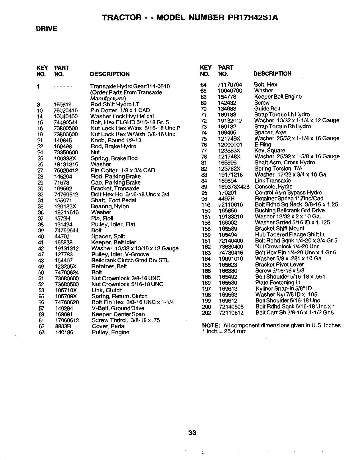
DRIVE
TRACTOR - - MODEL NUMBER PR17H425 JA
KEY
NO.
8
10
14
15
16
19
21
22
24
25
26
27
26
29
3O
32
34
35
36
37
38
39
4O
41
42
47
48
49
5O
51
52
53
55
56
57
59
61
62
63
PART
NO.
165619
76020416
1004040O
74490544
73800500
738006O0
14O845
169498
73350600
106888X
19131316
76020412
145204
71673
169592
74760512
155071
120183X
19211616
15721-1
131494
74760644
4470J
165838
19131312
127783
154407
123205X
74760624
7368O600
73680500
105710X
10570gx
74760620
140294
169691
17060612
8883R
140186
KEY PART
DESCRIP_ON NO. NO. DESCRIPTION
Transaxle Hydro Gear 314-0510 64 71170764
(Order Parts From Transaxle 65 10040700
Manufacturer) 66 154778
Rod Shift Hydro LT 69 142432
Pin Cotter 1/8 x 1 CAD 70 134683
Washer Lock Hvy Helical 71 169183
Bolt, Hex FLGHD 5/16-18 Gr. 5 72 19132012
Nut Lock Hex W/Ins 5/16-18 Unc P 73 169182
Nut Lock Hex W/Wsh 3/8-16 Unc 74 169496
Knob, Round 1/2-13 75 121749X
Rod, Brake Hydro 76 12000001
Nut 77 123583X
Spring, Brake Rod 78 121748X
Washer 81 165596
Pin Cotter 1/8 x 3/4 CAD. 82 123782X
Rod, Parking Brake 83 19171216
Cap, Parking Brake 84 169594
Bracket, Transaxle 89 169373X428
Bolt Hex Hd 5/16-18 Unc x 3/4 95 170201
Shaft, Foot Pedal 96 44971-1
Bearing,Nylon 116 72110610
Washer 150 165850
Pin, Roll 151 19133210
Pulley, Idler, Flat 156 166002
Bolt 158 165589
Spacer, Split 159 165494
Keeper, Belt Idler 161 72140406
Washer 13/32 x 13/16 x 12 Gauge 162 73680400
Pulley, Idler, V-Groove 163 74780416
Bellcrank Clutch Grnd Dry STL 164 19091010
Retainer, Belt 165 165623
Bolt 166 166880
Nut Crownlock 3/8-16 UNC 168 165492
Nut Crownlock 5/16-18 UNC 169 165580
Link, Clutch 197 169613
Spring, Return, Clutch 198 169593
Bolt Fin Hex 3/8-16 UNC x 1-1/4 199 169612
V-Belt, Ground Drive 200 72140508
Keeper, Center Span 202 72110612
Screw Thdrol. 3/8-16 x .75
Cover, Pedal
Pulley, Engine
Bolt, Hex
Washer
Keeper Belt Engine
Screw
Guide Belt
StrapTorque LhHydro
Washer 13/32 x 1-1/4 x 12 Gauge
StrapTorque RhHydro
Spacer, Axle
Washer 25/32 x 1-1/4 x 16 Gauge
E-Ring
Key, Square
Washer 25/32 x 1-5/8 x 16 Gauge
Shaft Asm. Cross Hydro
Spring Torsion T/A
Washer 17/32 x 3/4 x 16 Ca.
LinkTransaxle
Console, Hydro
Control Asm Bypass Hydro
Retainer Spring 1" Zinc/Cad
Bolt Rdhd Sq Neck 3/8-16 x 1.25
Bushing Bellcrank Grd Ddve
Washer 13/32 x 2 x 10 Ca.
Washer Srrted 5/16 ID x 1.125
Bracket Shift Mount
Hub Tapered Flange Shift Lt
Bolt Rdhd Sqnk 1/4-20 x 3/4 Gr 5
Nut Crownlock 1/4-20 Unc
Bolt Hex Fin 1/4-20 Unc x 1 Gr 5
Washer 5/8 x .281 x 10 Ga
Bracket Pivot Lever
Screw 5/16-18 x 5/8
BoltShoulder 5/16-18 x .561
Plate Fastening Lt
Nyliner Snap-In 5/8" ID
Washer Nyl 7/8 ID x .105
Bolt Shoulder 5/16-18 Unc
Bolt Rdhd Sqnk 5/16-18 Unc x 1
BoltCarr Sh 3/8-16 x 1-1/2 Gr 5
NOTE: All component dimensions given in U.S. inches
1 inch = 25.4 mm
33
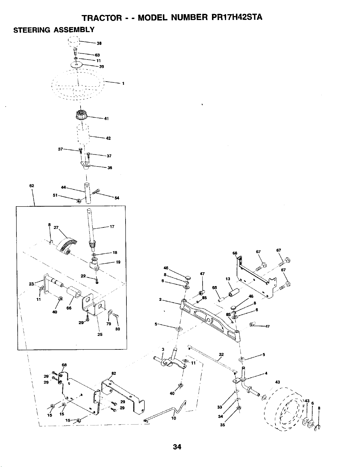
TRACTOR - - MODEL NUMBER PR17H42STA
STEERING ASSEMBLY
qL_ - "_,_'-"-'_ 38
' / i
i I ....
62
,_----'_ 42
i
8
11
68
29
80
25
82
29
68 67 67
6 _ 13
34
35
43
I /1tl
34
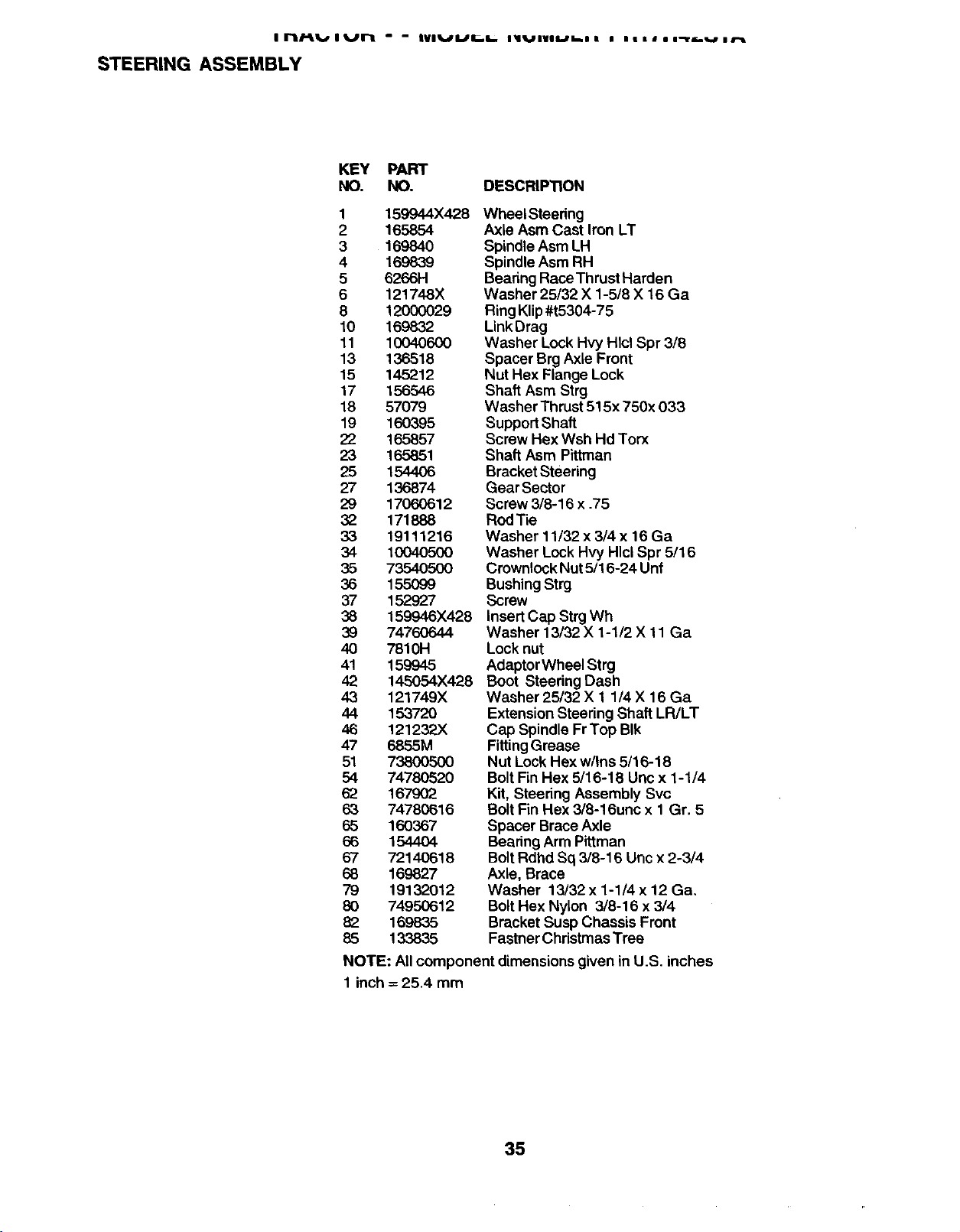
I rl/-ll, allJrl - - IVlI./L/I_.I. l_llJl|ll./l_l! i llilil-lri._.,alr.l
STEERING ASSEMBLY
KEY PART
NO. NO. DESCRIPTION
1 159944X428
2 165854
3 169840
4 169839
5 6266H
6 121748X
8 12000029
10 169832
11 10040600
13 136518
15 145212
17 156546
18 57079
19 160395
22 165857
23 165851
25 1544O6
27 136874
29 17060612
32 171888
33 19111216
34 10040500
35 73540500
36 155099
37 152927
38 159946)(428
39 74760644
40 7810H
41 159945
42 145054X428
43 121749X
44 153720
46 121232X
47 6855M
51 73800500
54 74780520
62 167902
63 74780616
65 160367
66 154404
67 72140618
68 169827
79 19132012
80 74950612
82 169835
85 133835
Wheel Steering
Axle Asm Cast Iron LT
Spindle Asm LH
Spindle Asm RH
Bearing Race Thrust Harden
Washer 25/32 X 1-5/8 X 16 Ga
Ring Klip #t5304-75
LinkDrag
Washer Lock Hvy Hlcl Spr 3/8
Spacer Brg Axle Front
Nut Hex Flange Lock
Shaft Asm Strg
Washer Thrust 515x 750x 033
Support Shaft
Screw Hex Wsh Hd Torx
Shaft Asm Pittman
Bracket Steering
Gear Sector
Screw 3/8-16 x .75
Rod Tie
Washer 11/32 x 3/4 x 16 Ga
Washer Lock Hvy Hlcl Spr 5/16
Crownlock Nut 5/16-24 Unf
Bushing Strg
Screw
Insert Cap Strg Wh
Washer 13/32 X 1-1/2 X 11 Ga
Lock nut
Adaptor Wheel Strg
Boot Steering Dash
Washer 25/32 X 1 1/4 X 16 Ga
Extension Steering Shaft LR/LT
Cap Spindle Fr Top BIk
FittingGrease
Nut Lock Hex w/Ins 5/16-18
Bolt Fin Hex 5/16-18 Unc x 1-1/4
Kit, Steering Assembly Svc
Bolt Fin Hex 3/8-16unc x 1 Gr. 5
Spacer Brace Axle
Bearing Arm Pittman
Bolt Rdhd Sq 3/8-16 Unc x 2-3/4
Axle, Brace
Washer 13/32 x 1-1/4 x 12 Ga,
Bolt Hex Nylon 3/8-16 x 3/4
Bracket Susp Chassis Front
Fastner Christmas Tree
NOTE: All component dimensions given in U.S. inches
1 inch = 25.4 mm
35
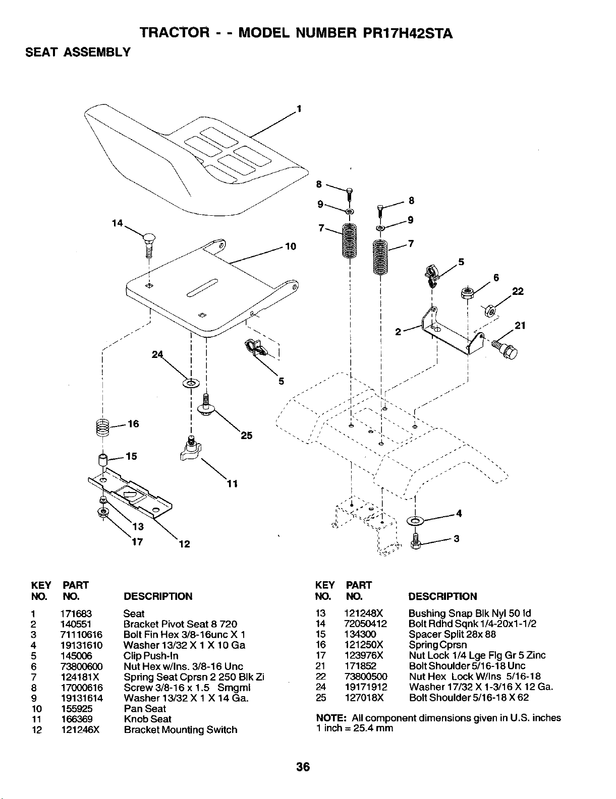
TRACTOR - - MODEL NUMBER PR17H42STA
SEAT ASSEMBLY
25
11
5
5
21
KEY
NO.
1
2
3
4
5
6
7
8
9
10
11
12
PART
NO.
171683
140551
71110616
19131610
145OO6
738006O0
124181X
17000616
19131614
155925
166369
121246X
DESCRIPTION
Seat
Bracket Pivot Seat 8 720
Bolt Fin Hex 3/8-16unc X 1
Washer 13/32 X 1 X 10 Ga
Clip Push-In
Nut Hex w/Ins. 3/8-16 Unc
Spring Seat Cprsn 2 250 BIk Zi
Screw 3/8-16 x 1.5 Smgml
Washer 13/32 X 1 X 14 Ga.
Pan Seat
Knob Seat
Bracket Mounting Switch
KEY PART
NO, NO. DESCRIPTION
13 121248X
14 72050412
15 134300
16 121250X
17 123976X
21 171852
22 73800500
24 19171912
25 127018X
Bushing Snap BIk Nyl 50 Id
Bolt Rdhd Sqnk 1/4-20x1-1/2
Spacer Split 28x 88
Spring Cprsn
Nut Lock 1/4 Lge Fig Gr 5 Zinc
Bolt Shoulder 5/16-18 Unc
Nut Hex Lock W/Ins 5/16-18
Washer 17/32 X 1-3/16 X 12 Ga.
Bolt Shoulder 5/16-18 X 62
NOTE: All component dimensions given in U.S. inches
1 inch = 25.4 mm
36
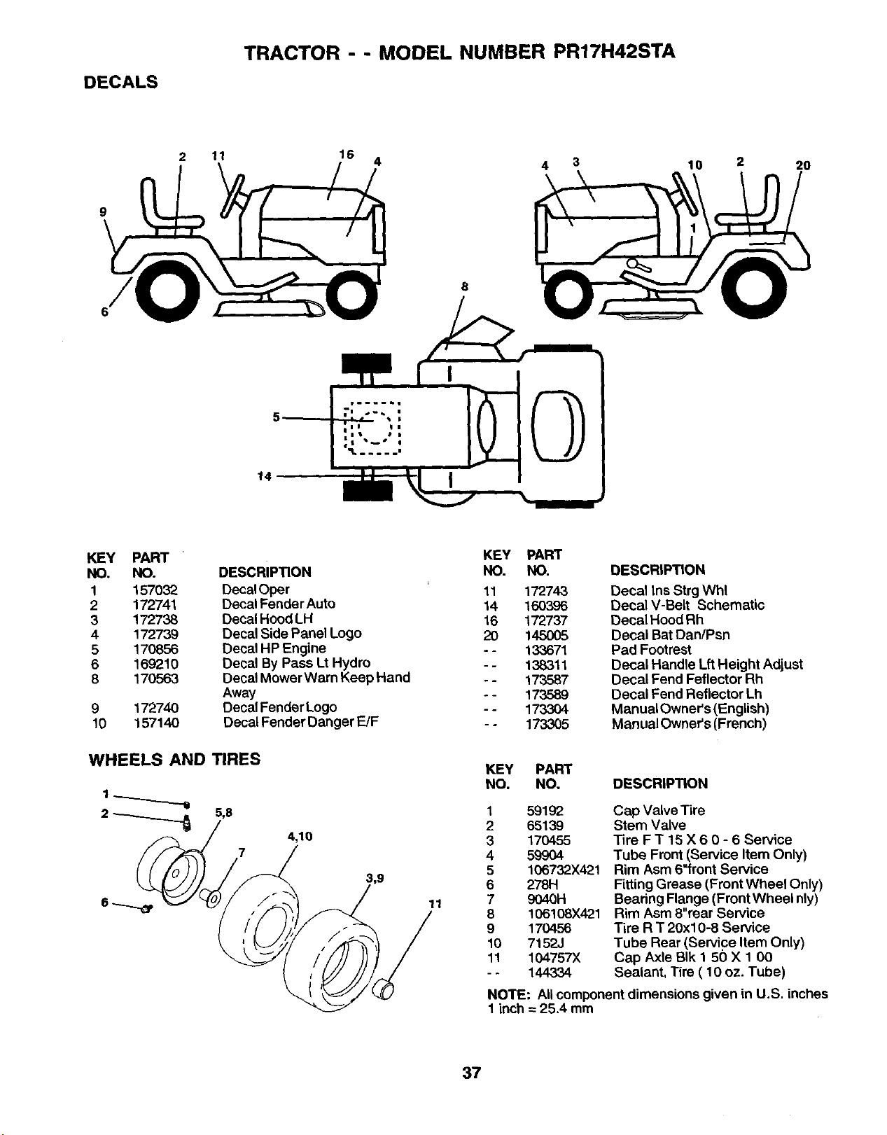
DECALS
TRACTOR - - MODEL NUMBER PR17H42STA
11
16
4
4 3 10 2 20
9
14
KEY PART
NO. NO.
1 157032
2 172741
3 172738
4 172739
5 170856
6 169210
8 170563
9 172740
10 157140
DESCRIPTION
Decal Oper
Decal Fender Auto
Decal Hood LH
Decal Side Panel Logo
Decal HP Engine
Decal By Pass Lt Hydro
Decal Mower Warn Keep Hand
Away
Decal Fender Logo
Decal Fender Danger E/F
WHEELS AND TIRES
5,8
7
4,10
11
KEY PART
NO. NO.
11 172743
14 160396
16 172737
20 145005
- - 133671
- - 138311
- - 173587
- - 173589
- - 173304
- - 173305
DESCRIPTION
Decal Ins Strg Whl
Decal V-Belt Schematic
Decal Hood Rh
Decal Bat Dan/Psn
Pad Footrest
Decal Handle Lft Height Adjust
Decal Fend Feflector Rh
Decal Fend Reflector Lh
Manual Owner's (English)
Manual Owner's (French)
KEY PART
NO. NO. DESCRIPTION
1 59192
2 65139
3 170455
4 59904
5 106732X421
6 2781-1
7 9040H
8 106108X421
9 170456
10 7152J
11 104757X
-- 144334
Cap Valve Tire
Stem Valve
Tire F T 15 X 6 0- 6 Service
Tube Front (Service Item Only)
Rim Asm 6"front Service
Fitting Grease (Front Wheel Only)
Bearing Flange (Front Wheel nly)
Rim Asm 8"rear Service
Tire R T 20xl 0-8 Service
Tube Rear (Service Item Only)
Cap Axle BIk 1 50 X 1 00
Sealant, Tire ( 10 oz. Tube)
NOTE: Allcomponent dimensions given in U.S. inches
1 inch = 25.4 mm
37
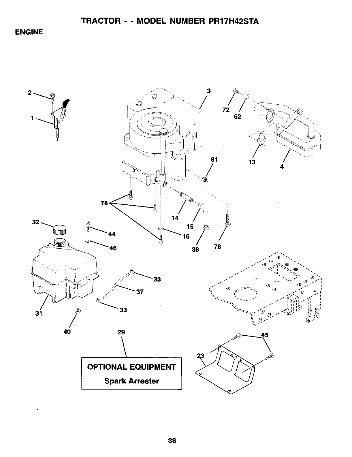
ENGINE
TRACTOR - - MODEL NUMBER PR17H42STA
31
4O
/
©
81
72
78 .
I
14 15
38 78
33
• 37,,/
33
29
62
13
4
I OPTIONAL EQUIPMENT I
Spark Arrester
38

ENGINE
TRACTOR - - MODEL NUMBER PR17H42STA
KEY PART
NO. NO, DESCRIPTION
1
2
3
14O310
17720410
4 137352
13 165291
14 13280324
15 13200300
16 11950600
23 169837
29 137180
31 161911
32 140527
33 123487X
37 137040
8 .......
40 124028X
44 17670412
45 17000612
46 19091416
62 10040500
72 71070512
78 17O6O62O
81 73510400
Control Th/ch 23 5 LH Flag
Screw Hex Thd Cut 1/4-20x5/8 T
Engine, Bdggs Model 311777
(Order Parts From Engine Manufacturer)
Muffler
Gasket Eng
Nipple Pipe
Elbow Std 90 Degree 3/8-18 Npt
Washer Lock Ext Tooth 3/8
Shield BrrdDbrGuard
Kit Spark Arrestor (Flat Scm)
Tank Fuel Front 2 00
Cap Asm Fuel W/sym Vented
Clamp Hose Black
Line Fuel 20"
Plug Oil Drain
(Order From Engine Manufacturer)
Bushing Snap Nyl BIk Fuel Line
Screw Hexwsh Thdrol 1/4-20x3/4
Screw Hexwsh Thdr 3/8-16 x 3/4
Washer 9/32 X 7/8 X 16 Ga
Washer Lock Hvy Hlcl Spr 5/16
Screw Hex Hd Cap 5/16-18 x 3/4
Screw3/8-16xl-1/4
Nut Keps Hex 1/4-20 UNC
NOTE: Allcomponent dimensions given in U. S.
inches 1 inch= 25.4 mm
39
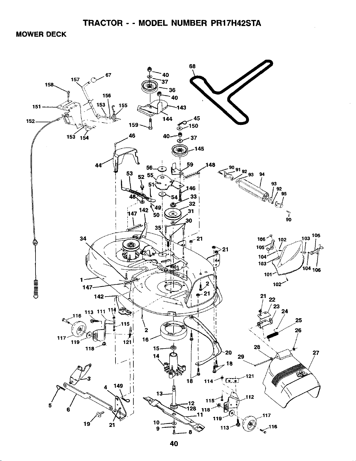
MOWER DECK
TRACTOR - - MODEL NUMBER PR17H42STA
+
157 _67
156
153 154
34
I
/
"®/21
93 94
I
9o
101'
lO2/_
116 113 111 11_
_ _,_115
119" _ ' 121 I
118F I
!°zi
I
4 149 [
21
22
/ 23
\
2
16 ,.
1_ 28 \-
1 29
18
_121
18 114 / i
_ 12 11
_128 118_
_. 11 119._i../, 117
9 _ 113 116
24
103 105
25
26
27
40
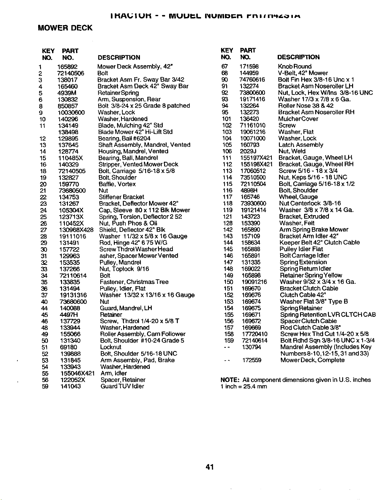
MOWER DECK
IHAUIUH - - MUUI:L I_lUIVlDIr.ri rrilln_¢o,_
KEY PART
NO. NO.
1 165892
2 72140506
3 138017
4 165460
5 4939M
6 130832
8 850857
9 10030600
10 140296
11 134149
138498
12 129895
13 137645
14 128774
15 110485X
16 140329
18 72140505
19 132827
20 159770
21 73680500
22 134753
23 131267
24 105304X
25 123713X
26 110452X
27 130968X428
28 19111016
29 131491
30 157722
31 129963
32 153535
33 137266
34 72110614
35 133835
36 131494
37 19131316
40 73680600
44 140088
45 4.497H
46 137729
48 133944
49 155066
50 131340
51 69180
52 139888
53 131845
54 133943
55 155046X421
56 122052X
59 141043
DESCRIPTION
KEY
NO.
Mower Deck Assembly, 42" 67
Bolt 68
Bracket Asm Fr. Sway Bar 3/42 90
Bracket Asm Deck 42" Sway Bar 91
Retainer Spdng 92
Arm, Suspension, Rear 93
Bolt 3/8-24 x 25 Grade 8 patched 94
Washer, Lock 95
Washer, Hardened 101
Blade, Mulching 42" Std 102
Blade Mower 42" Hi-Lift Std 103
Bearing, Ball#6204 104
Shaft Assembly, Mandrel, Vented 105
Housing, Mandrel, Vented 106
Beadng, Ball, Mandrel 111
Stripper,Vented Mower Deck 112
Bolt,Carriage 5/16-18 x 5/8 113
Bolt,Shoulder t 14
Baffle, Vortex 115
Nut 116
Stiffener Bracket 117
Bracket, Deflector Mower 42" t t8
Cap, Sleeve 80 x 112 BIk Mower 119
Spdng, Torsion, Deflector 2 52 121
Nut, Push Phos & Oil 128
Shield, Deflector 42" Bik 142
Washer 11/32 x 5/8 x 16 Gauge 143
Rod, Hinge 42" 6 75 WIG 144
Screw Thdrol Washer Head 145
asher, Spacer Mower Vented 146
Pulley, Mandrel 147
Nut, Toplock 9/16 148
Bolt 149
Fastener, Christmas Tree 150
Pulley, Idler, Flat 151
Washer 13/32 x 13/16 x 16 Gauge 152
Nut 153
Guard, Mandrel, LH 154
Retainer 155
Screw, Thdrol 1/4-20 x 5/8 T 156
Washer, Hardened 157
Roller Assembly, Cam Follower 158
Bolt,Shoulder #10-24 Grade 5 159
Locknut - -
Bolt, Shoulder 5/16-18 UNC
Arm Assembly, Pad, Brake
Washer, Hardened
Arm, Idler
Spacer, Retainer
GuardTUV Idler
PART
NO.
171598
144959
747606t 6
132274
7380O6OO
19171416
132264
132273
136420
71161010
19061216
10071000
160793
2029J
155197X421
155198X421
17060512
73510500
72110504
48981,1
165746
73930600
19121414
143723
153390
16,589O
157109
158634
165888
165891
131335
169022
165898
19091216
169670
169676
16,9674
169675
169671
169672
169669
17720410
72140614
130794
172559
DESCRIPTION
Knob Round
V-Belt, 42" Mower
Bolt Fin Hex 3/8-16 Unc x 1
Bracket Asm NoseroUer LH
Nut, Lock, Hex W/Ins 3/8-16 UNC
Washer 17/3 x 7/8 x 6 Ca.
Roller Nose 38 &42
Bracket Asm Noseroller RH
MulcherCover
Screw
Washer, Flat
Washer, Lock
Latch Assembly
Nut, Weld
Bracket, Gauge, Wheel LH
Bracket, Gauge, Wheel RH
Screw 5/16 - 18 x 3/4
Nut, Keps 5/16 - 18 UNC
Bolt, Carriage 5/16-18 x 1/2
Bolt,Shoulder
Wheel, Gauge
Nut Centedock 3/8-16
Washer 3/8 x 7/8 x 14 Ga.
Bracket, Extruded
Washer, Felt
Arm Spring Brake Mower
Bracket Arm Idler 42"
Keeper Belt 42" Clutch Cable
Pulley Idler Flat
Bolt Carriage Idler
Spring Extension
Spring Return Idler
Retainer Spring Yellow
Washer 9/32 x 3/4 x 16 Ca.
Bracket Clutch Cable
Clutch Cable 42"
Washer Flat 3/8" Type B
Spring Retainer
Spring Retention LVR CLTCH CAB
Spacer Clutch Cable
Rod Clutch Cable 3/8"
Screw Hex Thd Cut 1/4-20 x 5/8
Bolt Rdhd Sqn 3/8-16 UNC x 1-3/4
Mandrel Assembly (Includes Key
Numbers 8-10,12-15, 31 and 33)
Mower Deck, Complete
NOTE: All component dimensions given in U.S. inches
1 inch = 25.4 mm
41
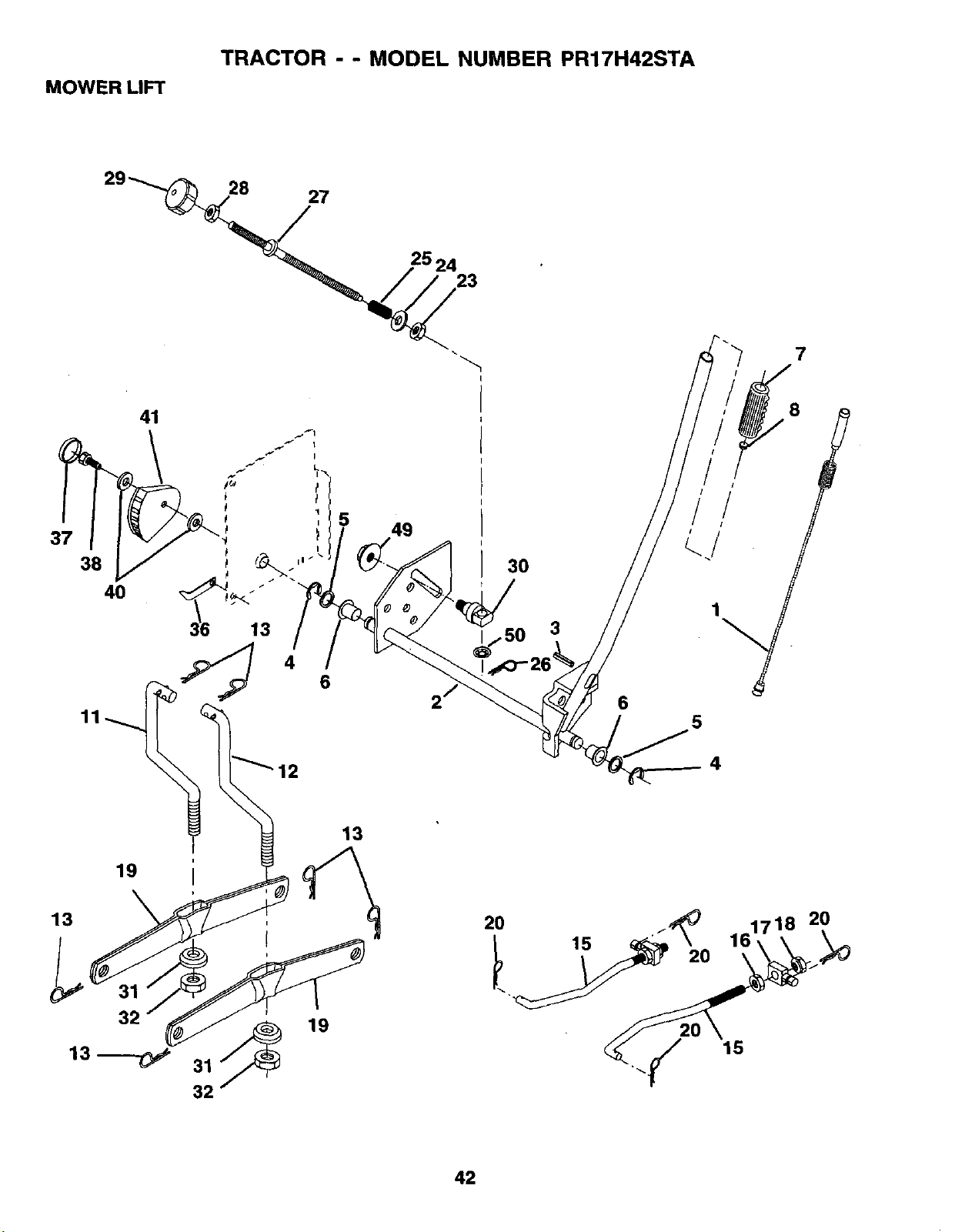
MOWER LIFT
TRACTOR - - MODEL NUMBER PR17H42STA
29_
28
27
25 24
23
7
38
4O
41
4
6
49
30
1/50
3
6
/
!
f
1
5
4
19
13
13 , 20 ./'_ 161718 20
{ _ 15 20
32 _ 19 _/ 15
13 '_--C_ 31 -.
32
42
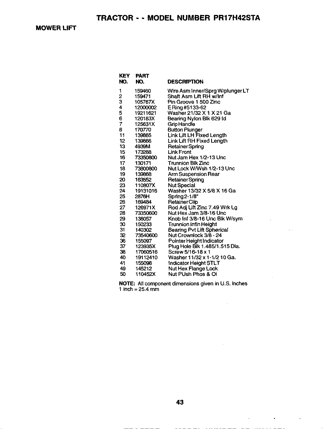
MOWER LIFT
TRACTOR - - MODEL NUMBER PR17H42STA
KEY PART
NO. NO. DESCRIPTION
1 159460
2 159471
3 105767X
4 12000002
5 19211621
6 120183X
7 125631X
8 170770
11 139865
12 139866
13 4939M
15 173288
16 73350800
17 130171
18 738OO800
19 139868
2O 163552
23 110807)(
24 19131016
25 2876H
26 169484
27 126971X
28 73350600
29 138057
30 150233
31 140302
32 73540600
36 155097
37 123935X
38 17060516
40 19112410
41 155098
49 145212
50 110452X
Wire Asm InnedSprg W/plunger LT
Shaft Asm Lift RH w/Inf
Pin Groove 1 500 Zinc
E Ring#5133-62
Washer 21/32 X 1 X 21 Ga
Bearing Nylon BIk 629 Id
Grip Handle
Button Plunger
Link LiftLH Fixed Length
Link Lift RH Fixed Length
Retainer Spring
LinkFront
Nut Jam Hex 1/2-13 Unc
Trunnion BIk Zinc
Nut Lock W/Wsh 1/2-13 Unc
Arm Suspension Rear
Retainer Spring
Nut Special
Washer 13/32 X 6/8 X 16 Ga
Spring 2-1/8"
RetainerClip
Rod Adj Lift Zinc 7.49 Wrk Lg
Nut Hex Jam 3/8-16 Unc
Knob Inf 3/8-16 Unc BIk W/sym
Trunnion Infln Height
Beadng Pvt Lift Spherical
Nut Crownlock 3/8 - 24
Pointer Height indicator
Plug Hole BIk 1.485/1.515 Dia.
Screw 5/16-18 x 1
Washer 11/32 x 1-1/2 10 Ga.
indicator Height STLT
Nut Hex Flange Lock
Nut PUsh Phos & Oi
NOTE: All component dimensions given in U.S. inches
1 inch = 25.4 mm
43

SERVICE NOTES
44

SERVICE NOTES
45

LIMITED WARRANTY
The Manufacturer warrants to the odginal consumer pumhaser that this product as manufactured is free from defects in
materials and workmanship. For a period of two (2) years from date of purchase by the original consumer purchaser, we will
repair or replace, at our option, without charge for parts or labor incurred in replacing parts, any part which we find to be
defective due to materials or workmanship. This Warranty is subject to the following limitations and exclusions.
1. This warranty does not apply to the engine, other than FHP manufactured transaxle/transmission components, battery
(except as noted below) or components parts thereof. Please refer to the applicable manufacturer's warranty on these
items.
2,
3.
4,
5.
6.
Transportation charges for the movement of any power equipment unit or attachment are the responsibility of the
purchaser. Transportation charges for any parts submitted for replacement under this warranty must be paid by the
purchaser unless such return is requested by Fdgidaire Home Products.
Battery Warranty: On products equipped with a Battery, we will replace, without charge to you, any battery which we find
to be defective in manufacture, during the first ninety (90) days of ownership. After ninety (90) days, we will exchange
the Battery, charging you 1/12 of the price of a new Battery for each full month from the date of the odginai sale. Battery
must be maintained in accordance with the instructions furnished.
The Warranty pedod for any products used for rental or commercial purposes is limited to 90 days from the date of
original purchase.
This Warranty applies only to products which have been properly assembled, adjusted, operated, and maintained in
accordance with the instructions furnished. This Warranty does not apply to any product which has been subjected to
alteration, misuse, abuse, improper assembly or installation, delivery damage, or to normal wear of the product.
Exclusions: Excluded from this Warranty are belts, blades, blade adapters, normal wear, normal adjustments, standard
hardware and normal maintenance.
7. in the event you have a claim under this Warranty, you must return the product to an authorized service dealer.
Should you have any unanswered questions conceming this Warranty, please contact:
Frigidaire Home Products
Outdoor Products Customer Service Dept.
250 Bobby Jones Expressway
Augusta, GA 30909 USA
In Canada contact:
Frigidaire Home Products
7075 Ordan Drive
Mississauga, Ontario
L5T 1K6
giving the model number, serial number and date of purchase of your product and the name and address of the authorized
dealer from whom it was purchased.
THIS WARRANTY DOES NOT APPLY TO INCIDENTAL OR CONSEQUENTIAL DAMAGES AND ANY IMPLIED WARRAN-
TIES ARE LIMITED TO THE SAME TIME PERIODS STATED HEREIN FOR OUR EXPRESSED WARRANTIES. Some areas
do not allow the limitation of consequential damages or limitations of how long an implied Warranty may last, so the above
limitations or exclusions may not apply to you. This Warranty gives you specific legal rights, and you may have other dghts
which vary from locale to locale.
This is a limited Warranty within the meaning of that term as defined in the Magnuson-Moss Act of 1975.
=
46

SUGGESTED GUIDE FOR SIGHTING SLOPES FOR SAFE OPERATION
".d
ONLY RIDE UP AND DOWN HILL,
NOT ACROSS HILL
,-..,,
SIGHT AND HOLD THIS LEVEL WITH
SKY LINE OR TREE.
15° MAX.
t/_ perate your Tractor up and down the face of slopes (not
greater than 15°.), never across the face. Make turns gradu-
ally to prevent tipping or !oss of control. Exercise extreme
caution when changing direction on slopes, i
PARTS AND SERVICE
Your POULAN PRO product has been expertly engineered and carefully manufactured to rigid quality
standards. As with all mechanical products, some adjustments or part replacement may be necessary during
the life of your unit.
FOR SERVICE OR REPLACEMENT PARTS:
1. Consult your dealer/place of purchase.
2. Consult the yellow pages of your phone directory for the name of the nearest service dealer (under "saws"
for Chain Saws or under "lawn mowers" for Trimmers, Brushcutters, and Blowers).
3. For replacement parts, have available the following information:
a. Modal Number/Manufacturer's I.D. Number.
b. Description of part.
NOTE:
Frigidaire Home Products provides parts and service through its authorized distributors and
dealers; therefore, all requests for parts and service should be directed to your local dealer(s). The
philosophy of Frigidaire Home Products is to continually improve all of its products. If the
operating characteristics or the appearance of your product differs from those described in this
Manual, please contact your local local dealer for updated information and assistance.

