7387186 (Rev. B 10/20/23)
How to install, operate and
maintain your Whole Home
Water Filtration System
If you have any questions or concerns when in -
stalling, operating or maintaining your Whole Home
Water Filtration System, call our toll free number:
1-888-64 WATER
(1-888-649-2837)
or visit www.mortonwatersofteners.com
When you call, please be prepared to provide
the model and serial number of your product,
located on the rating decal on back of the cover.
Model MCWF
System tested and certified by NSF International
against NSF/ANSI Standard 42
for the reduction of chlorine taste and odor,
and certified to NSF/ANSI Standard 372.
Installation and Operation Manual
Manufactured and warranted by
Water Channel Partners
1890 Woodlane Drive
Woodbury, MN 55125

2 Morton
®
Installation & Operation Manual
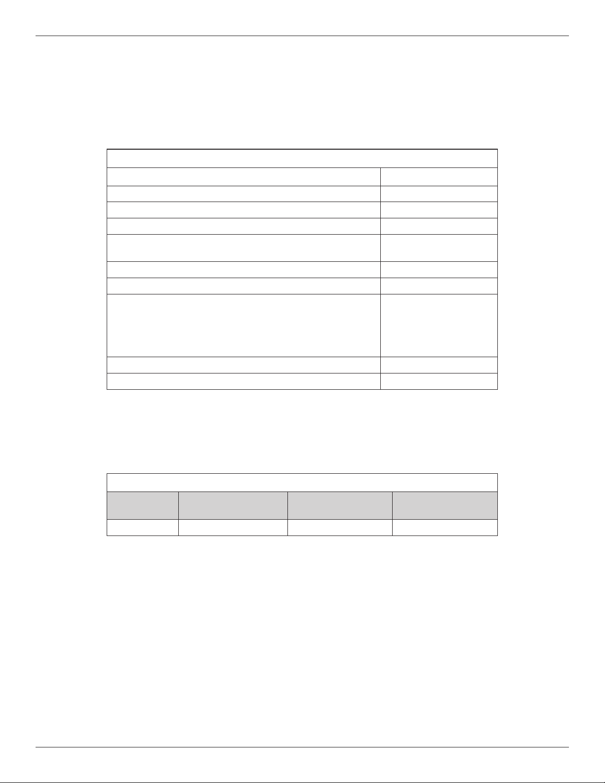
TABLE OF CONTENTS
Page
Specifications & Performance Claims . . . . . . . . . . . . . . . . . . . . . . . . . . . . . . . . . . . . . . . . . . . . . . . . . . . . . . . . . . . . 3
Dimensions . . . . . . . . . . . . . . . . . . . . . . . . . . . . . . . . . . . . . . . . . . . . . . . . . . . . . . . . . . . . . . . . . . . . . . . . . . . . . . . . 4
Inspect Shipment . . . . . . . . . . . . . . . . . . . . . . . . . . . . . . . . . . . . . . . . . . . . . . . . . . . . . . . . . . . . . . . . . . . . . . . . . . . . 5
Before You Start . . . . . . . . . . . . . . . . . . . . . . . . . . . . . . . . . . . . . . . . . . . . . . . . . . . . . . . . . . . . . . . . . . . . . . . . . . . . 6
How a Whole Home Water Filtration System Works . . . . . . . . . . . . . . . . . . . . . . . . . . . . . . . . . . . . . . . . . . . . . . . . 6
Installation Requirements . . . . . . . . . . . . . . . . . . . . . . . . . . . . . . . . . . . . . . . . . . . . . . . . . . . . . . . . . . . . . . . . . . . . 7-9
Installation Instructions . . . . . . . . . . . . . . . . . . . . . . . . . . . . . . . . . . . . . . . . . . . . . . . . . . . . . . . . . . . . . . . . . . . . 10-11
Programming the Whole Home Water Filtration System . . . . . . . . . . . . . . . . . . . . . . . . . . . . . . . . . . . . . . . . . . . . 12
Start Up Procedure . . . . . . . . . . . . . . . . . . . . . . . . . . . . . . . . . . . . . . . . . . . . . . . . . . . . . . . . . . . . . . . . . . . . . . . . . 13
Customizing Features / Options . . . . . . . . . . . . . . . . . . . . . . . . . . . . . . . . . . . . . . . . . . . . . . . . . . . . . . . . . . . . . 14-15
Care of Your Whole Home Water Filtration System . . . . . . . . . . . . . . . . . . . . . . . . . . . . . . . . . . . . . . . . . . . . . . . . 16
Troubleshooting . . . . . . . . . . . . . . . . . . . . . . . . . . . . . . . . . . . . . . . . . . . . . . . . . . . . . . . . . . . . . . . . . . . . . . . . . 17-18
Whole Home Water Filtration System Components . . . . . . . . . . . . . . . . . . . . . . . . . . . . . . . . . . . . . . . . . . . . . 20-23
WHOLE HOME WATER FILTRATION SYSTEM LIMITED WARRANTY
Warrantor guarantees to the original purchaser when the product is purchased from an authorized dealer, and
when installed and maintained in accordance with the instructions, that:
● For a period of ten (10) years from the date the product is delivered, the fiberglass filtration media tank will
not rust, corrode, leak, burst, or in any other manner, fail to perform in accordance with its written specifi-
cations.
● For a period of one (1) year from the date the product is delivered, all other parts will be free from defects
in materials and workmanship and will perform in accordance with their written specifications.
If, during such respective period, a part proves to be defective, Warrantor will ship a replacement part, directly
to your home, without charge. Labor necessary to maintain this product is not covered by the product warranty.
If you have questions regarding a Morton product, need assistance with installation or troubleshooting, wish to
order a part or report a warranty issue, we are just a phone call away. Simply dial 1-888-64WATER (1-888-
649-2837) for assistance, or visit www.mortonwatersofteners.com.
This whole home water filtration system is manufactured by Water Channel Partners, 1890 Woodlane Drive,
Woodbury, MN 55125.
General Provisions
The warranty does not apply to any defect, malfunction or failure arising from, relating to or caused by: (i)
operation at water pressures which exceed 125 psi or at water temperatures which exceed 100°F; (ii) repairs
made by others than, or without the consent of, Warrantor or if the product has been subject to abuse, misuse,
neglect, tampering, accident or damage by circumstances beyond Warrantor’s control; (iii) products damaged
or abused in shipment without fault of Warrantor; (iv) non-residential installations; (v) defects or failures due to
misapplication, abuse, improper installation or abnormal conditions of temperature, humidity, abrasives, dirt or
corrosive matter; (vi) unusual force of nature such as, but not limited to, flood, hurricane, tornado or earth-
quake; and (vii) products which have been in any way tampered with, modified or altered.
The foregoing warranties do not cover and Warrantor shall not be responsible for reimbursement for labor,
transportation, removal, installation, or other expenses which may be incurred by Purchaser in connection with
replacement or repair or returning the product to Warrantor.
THERE ARE NO WARRANTIES ON THE WHOLE HOME WATER FILTRATION SYSTEM BEYOND THOSE
SPECIFICALLY DESCRIBED ABOVE. ALL IMPLIED WARRANTIES, INCLUDING ANY IMPLIED WARRANTY
OF MERCHANTABILITY OR OF FITNESS FOR A PARTICULAR PURPOSE, ARE DISCLAIMED TO THE
EXTENT THEY MIGHT EXTEND BEYOND THE ABOVE PERIODS. THE SOLE OBLIGATION OF WARRAN-
TOR UNDER THESE WARRANTIES IS TO REPLACE OR REPAIR THE COMPONENT OR PART WHICH
PROVES TO BE DEFECTIVE WITHIN THE SPECIFIED TIME PERIOD, AND WARRANTOR IS NOT LIABLE
FOR CONSEQUENTIAL OR INCIDENTAL DAMAGES. NO DEALER, AGENT, REPRESENTATIVE, OR
OTHER PERSON IS AUTHORIZED TO EXTEND OR EXPAND THE WARRANTIES EXPRESSLY
DESCRIBED ABOVE.
Some states do not allow the exclusion or limitation of incidental or consequential damages, so the above limi-
tation or exclusion may not apply to you. This warranty gives you specific legal rights, and you may have other
rights which vary from state to state. This warranty applies to consumer-owned installations only.
Morton
®
Installation & Operation Manual 3
Specifications & Performance Claims
SPECIFICATIONS
Model MCWF
Rated Service Flow Rate 6.0 gpm (22.7 L/min.)
Pressure Drop at Rated Service Flow
10 psig
* (68.9 kPa)
Pressure Drop at 9.6 gpm
15 psig
* (103.4 kPa)
Water Pressure Limits (minimum / maximum)
30 - 125 psi
(206.8 - 861.8 kPa)
Water Temperature Limits (minimum / maximum) 40 - 100 °F (5 - 38 °C)
Drain Flow Rate 3.4 gpm
0.50 ppm
0.75 ppm
Rated Capacity at Chlorine Concentration** of: 1.0 ppm
1.5
ppm
2.0 ppm
2,280,000 gal.*
1,520,000 gal.*
1,140,000 gal.*
760,000 gal.*
570,000 gal.*
Sediment Removal with 30-40 micron particle size 95% or more
Sediment Removal with 40-50 micron particle size 99% or more
* From independent laboratory test data.
** Typical residential chlorine concentration is 0.5 to 1.0 ppm.
This system conforms to NSF/ANSI Standard 42 for the specific performance claims
as verified and substantiated by test data.
This system has been tested according to NSF/ANSI 42 for the reduction of chlorine taste and odor. The concentra-
tion of the indicated substance in water entering the system was reduced to a concentration less than or equal to the
permissible limit for water leaving the system, as specified in NSF/ANSI 42.
While testing was performed under standard laboratory conditions, actual performance of the system may vary
based on local water conditions.
PERFORMANCE CLAIMS
Substance
Influent
Challenge Level
Reduction
Requirement
Average Percent
Removal
Chlorine 2.0 ±10% mg/L 50% 82.8%
Questions? Call Toll Free 1-888-64 WATER (1-888-649-2837)
or visit
www.mortonwatersofteners.com
When you call, please be prepared to provide the model and serial number,
located on the rating decal on back of the cover.
4 Morton
®
Installation & Operation Manual
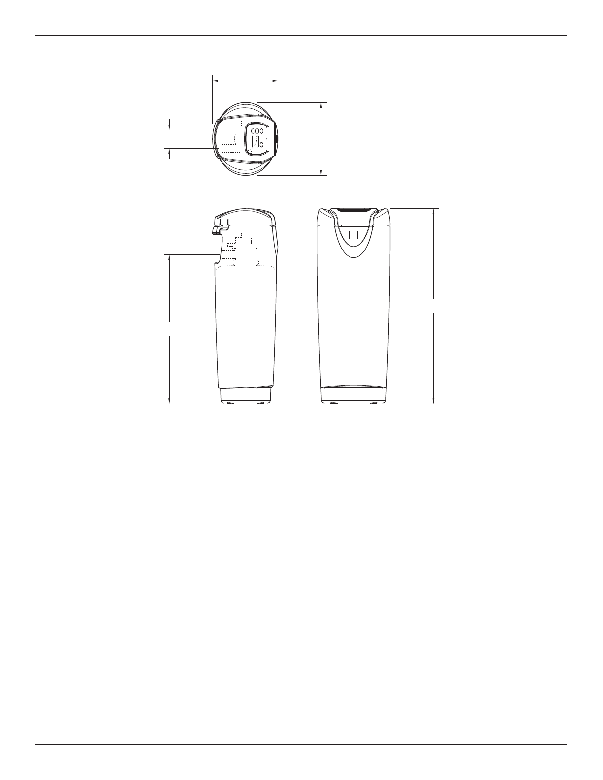
Dimensions
FRONT VIEWSIDE VIEW
36-1/8"
TOP VIEW
13-1/2"
12-1/8"
27-5/8"
3-3/8"
IN - OUT
IN
OUT
FIG. 1
27-5/8”
36-1/8”
3-3/8”
13-1/2”
12-1/8”
IN – OUT
OUT
IN
TOP VIEW
SIDE VIEW
FRONT VIEW
Morton
®
Installation & Operation Manual 5
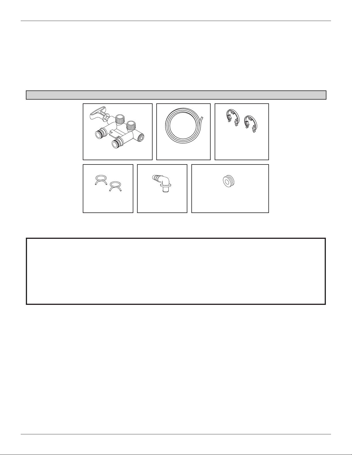
Packing List
Inspect Shipment
The parts required to assemble and install the Whole
Home Water Filtration System are included with the
unit. Thoroughly check the Whole Home Water
Filtration System for possible shipping damage and
parts loss. Also inspect and note any damage to the
shipping carton.
Remove and discard (or recycle) all packing materials.
To avoid loss of small parts, we suggest you keep the
small parts in the parts bag until you are ready to use
them.
Do not return the Whole Home Water Filtration System to store.
If you have any questions, or there are missing parts or damage, please call Toll Free 1-888-64 WATER
(1-888-649-2837).
When you call, please be prepared to provide the model and serial number, found on the rating decal on
back of the cover.
For more installation or service information, visit www.mortonwatersofteners.com.
Drain Hose
Bypass Valve
Adaptor Elbow
FIG. 2
Hose Clamps
Grommet (used for Models
M20, M27, M30 & M34)
Clips
(shipped installed on
the softener’s valve)
6 Morton
®
Installation & Operation Manual
How a Whole Home Water Filtration System Works
Normal Operation
During normal operation water enters the Whole Home
Water Filtration System and flows through several fil-
tration processes where tastes, odors and sediment
are reduced.
Clean Rinse Cycle
A Clean Rinse cycle will automatically be initiated
based on how the controller has been programmed.
The Clean Rinse cycle lifts and expands the media
bed to rejuvenate the media and then repacks the bed
for continued use. During the Clean Rinse cycle, dirt,
sediment, etc. are flushed from the Whole Home
Water Filtration System down the drain.
Applications for a Whole Home
Water Filtration System
= Do not use the Whole Home Water Filtration
System with water that is microbiologically unsafe
or of unknown quality without adequate disinfection
before or after the system.
= The Whole Home Water Filtration System may not
be an effective treatment method for water sources
with a hydrogen sulfide problem (rotten egg odor or
taste) If your water has hydrogen sulfide, contact a
water treatment expert or call 1-888-64
WATER.
= The Whole Home Water Filtration System will not
remove iron and is not intended to replace iron
treatment equipment.
= Although the Whole Home Water Filtration System
has sediment filter capabilities, additional sediment
filtration may be needed in problem water applica-
tions.
= Use care when handling the Whole Home Water Filtration System. Do not turn upside down, drop, or set on
sharp protrusions.
= The Whole Home Water Filtration System has a maximum allowable inlet water pressure of 125 psi and a minimum
of 30 psi. If daytime pressure is over 80 psi, nighttime pressure may exceed the maximum. Use a pressure
reducing valve if necessary (Adding a pressure reducing valve may reduce the flow.). If your home is equipped
with a back flow preventer, an expansion tank must be installed in accordance with local codes and laws.
= The Whole Home Water Filtration System works on 24V DC electrical power, supplied by a direct plug-in power
supply (included). Be sure to use the included power supply, and plug it into a nominal 120V, 60 Hz household
outlet that is in a dry location only, grounded and properly protected by an overcurrent device such as a circuit
breaker or fuse.
= Do not use the Whole Home Water Filtration System with water that is microbiologically unsafe or of unknown
quality without adequate disinfection before or after the system.
European Directive 2002/96/EC requires all electrical and electronic equipment to be disposed of accord-
ing to Waste Electrical and Electronic Equipment (WEEE) requirements. This directive or similar laws
are in place nationally and can vary from region to region. Please refer to your state and local laws for
proper disposal of this equipment.
Before You Start
In the state of Massachusetts: The Commonwealth of Massachusetts plumbing code 248-CMR
shall be adhered to. A licensed plumber shall be used for this installation.
Morton
®
Installation & Operation Manual 7
The Proper Order To Install Water Treatment Equipment
Location Requirements
Consider the following when selecting an installation
location for the Whole Home Water Filtration System.
= Do not operate the Whole Home Water Filtration
System where freezing temperatures occur. Do not
attempt to treat water over 100ºF (38ºC). Freezing
temperatures or hot water damage voids the warranty.
= To condition all water in the home, install the Whole
Home Water Filtration System close to the water
supply inlet, and before all other plumbing connec-
tions, except outside water pipes.
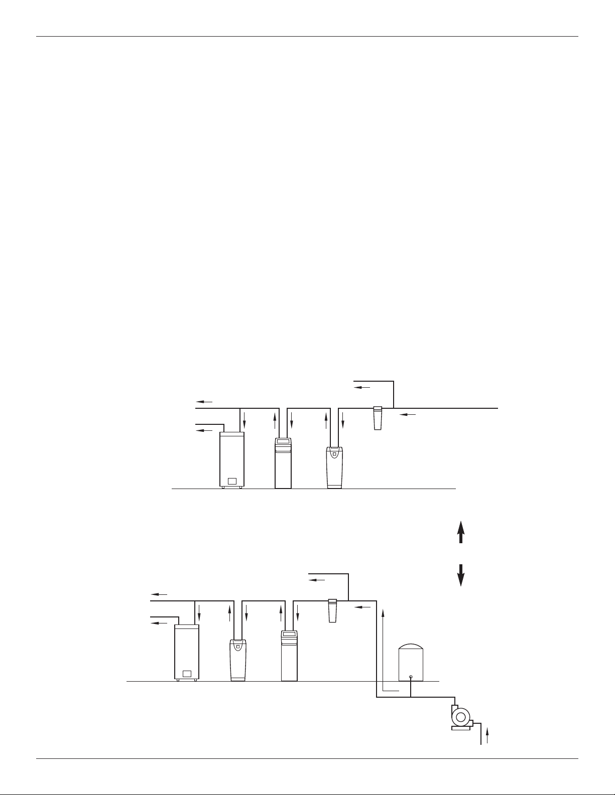
= For a home with municipal water supply, install the
Central Water Filtration System between the home’s
incoming water supply and the water softener, if one
is being used (See Figure 3A). If the home has well
water, reverse the order of the Central Water Filtra -
tion System and the water softener (See Figure 3B).
= A nearby drain is needed to carry away Clean
Rinse discharge water. Use a floor drain, laundry
tub, sump, standpipe, or other options (check your
Installation Requirements
local codes). See "Air Gap Requirements" and
"Valve Drain Requirements" sections. If a drain is
not available, it is still possible to operate the Whole
Home Water Filtration System in a manual Clean
Rinse mode. See “Operating in Manual Clean
Rinse Mode.” The automatic Clean Rinse must be
disabled if the Whole Home Water Filtration System
will not be connected to a drain (See Page 8).
= The Whole Home Water Filtration System works on
24V DC electrical power, supplied by a direct plug-
in power supply (included). Provide a 120V, 60 Hz
electrical outlet in accordance with NEC and local
codes.
= Do not install the Whole Home Water Filtration
System on a hot water line (See Figures 3A & 3B,
below).
= Avoid installing in direct sunlight. Excessive sun
heat may cause distortion or other damage to non-
metallic parts.
Untreated Water to
Outside Faucets
FIG. 3B
Hot Water
to House
Cold Water
to House
Untreated Water to
Outside Faucets
Water
Heater
Optional
Sediment
Filter
Pressure
Tank
Well
Pump
Hot Water
to House
Cold Water
to House
Whole Home
Water
Filtration
System
Water
Heater
Water
Softener
Optional
Sediment
Filter
City Water Supply
Well Water Supply
Whole Home
Water
Filtration
System
Water
Softener
FIG. 3A
OR
8 Morton
®
Installation & Operation Manual
Installation Requirements
Plumbing Codes
All plumbing must be completed in accordance with
national, state and local plumbing codes.
Valve Drain Requirements
Using the flexible drain hose (included), measure and
cut to the length needed. Flexible drain hose is not
allowed in all localities (check your plumbing codes). If
local codes do not allow use of a flexible drain hose, a
rigid valve drain run must be used. Purchase a com-
pression fitting (1/4 NPT x 1/2 in. minimum tube) and
1/2" tubing from your local hardware store. Plumb a
rigid drain as needed (see Figure 4, below).
NOTE: Avoid drain hose runs longer than 30 feet.
Make the valve drain line as short and direct
as possible.
It is recommended that the Whole Home Water Filtra -
tion System be installed near a drain. However, if a
drain is not available, it is still possible to operate the
Whole Home Water Filtration System in a manual
Clean Rinse mode. See “Operating in Manual Clean
Rinse Mode” section. The automatic Clean Rinse
function must be disabled if the Whole Home Water
Filtration System will not be connected to a drain.
Connecting Valve to Drain
In the state of Massachusetts: The Commonwealth
of Massachusetts plumbing code 248-CMR shall
be adhered to. A licensed plumber shall be used
for this installation.
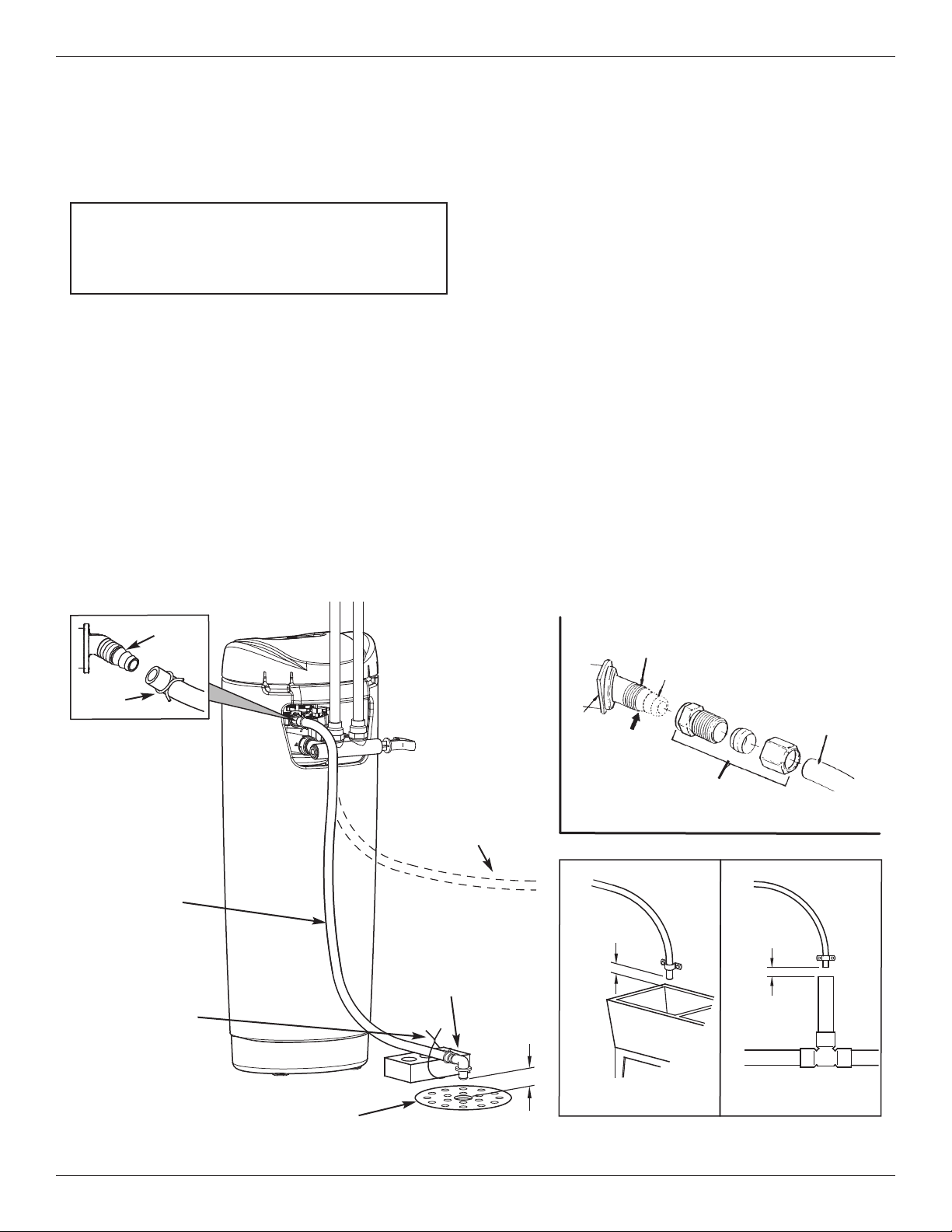
Air Gap Requirements
A drain is needed for Clean Rinse discharge water. A
floor drain, close to the Whole Home Water Filtration
System, is preferred. A laundry tub, standpipe, etc.
are other drain options. Secure valve drain hose in
place. Leave an air gap of 1-1/2” between the end of
the hose and the drain. This gap is needed to prevent
backflow of sewer water into the Whole Home Water
Filtration System . Do not put the end of the drain
hose into the drain.
1-1/2”
air gap
Install adaptor
elbow using hose
clamp. Aim noz-
zle down toward
center of drain
Tie or wire
tubing in
place
LAUNDRY TUB STANDPIPE
1-1/2”
air gap
FLOOR DRAIN
1-1/2”
air gap
To drain point other
than floor drain.
Support tubing in
place as needed.
Drain
Fitting
Clip
Barbs
1/4 NPT Threads
1/2” Outside Dia.
Copper Tube
(not included)
Comp Fitting. 1/4
NPT x 1/2” O.D.
Tube (not included)
Cut barbs from
drain fitting (pull
clip to remove fit-
ting from valve)
SUBSTITUTING RIGID DRAIN LINE
Hose
Clamp
Valve
Drain
Hose
Drain grate with 1”
dia. hole in center
FIG. 4
Morton
®
Installation & Operation Manual 9
Installation Requirements
Inlet - Outlet Plumbing Options
Always install either a single bypass valve (provided)
to the contractor/plumber-supplied plumbing, as shown
in Figure 7 OR if desired, a 3 valve bypass system
(parts not included) can be installed, as shown in
Figure 6. Bypass valves allow you to turn off water to
the Whole Home Water Filtration System for mainte-
nance if needed, but still have water in house pipes.
Use either:
= Copper pipe
= Threaded pipe
= PEX (Crosslinked Polyethylene) pipe
= CPVC plastic pipe
= Other pipe approved for use with potable water
IMPORTANT: Do not solder with plumbing attached to
the single valve bypass. Soldering heat
will damage the plasric valve.
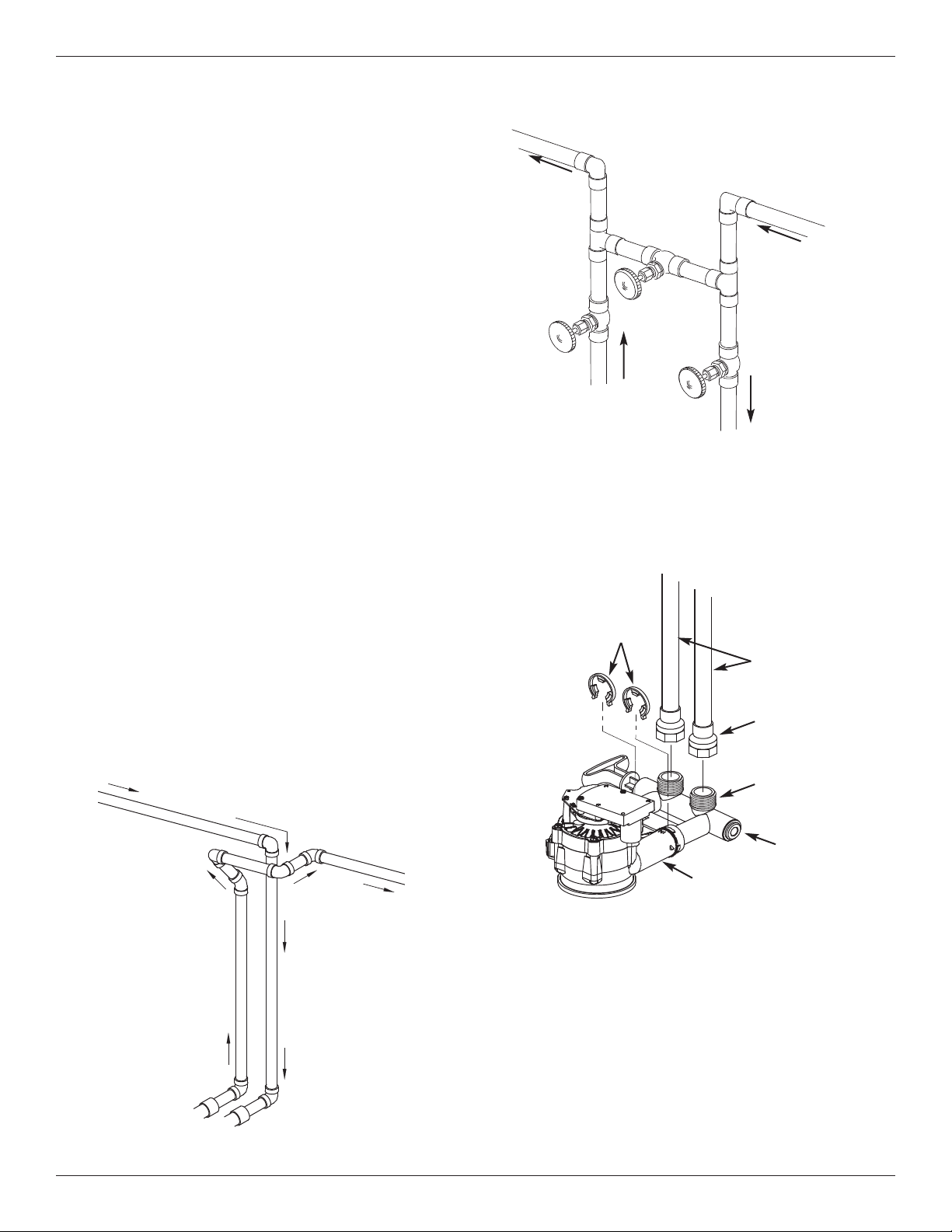
FIG. 6
3 Valve Bypass
Whole Home Water
Filtration System
INLET
Cross Over
FIG. 5
To Whole Home
Water Filtration System
Main Water Pipe
In what direction does the water flow?
Be sure to plan piping so water flow is to the
Whole Home Water Filtration System valve IN -
LET. Plan a crossover if flow is from left to right.
Treated
Water from
Valve
OUTLET
Whole Home Water
Filtration System
OUTLET
Untreated
Water to
Valve
INLET
FIG. 7
Connecting Plumbing to Valve
Pipes
Clips
1” NPT Sweat
Adapter (2)
(not included)
Bypass
Valve
Valve
Inlet
IN
OUT
Use Teflon® tape,
pipe joint com-
pound or both
10 Morton
®
Installation & Operation Manual
FIG. 9
Ground
Wire
Clamp (2)
Installation Instructions
Step 1. Turn Off Water Supply
1. Close the main water supply valve, near the well
pump or water meter.
2. Open all faucets to drain water from the house
pipes.
NOTE: Be sure not to drain water from the water
heater, as damage to the water heater ele-
ments could result.
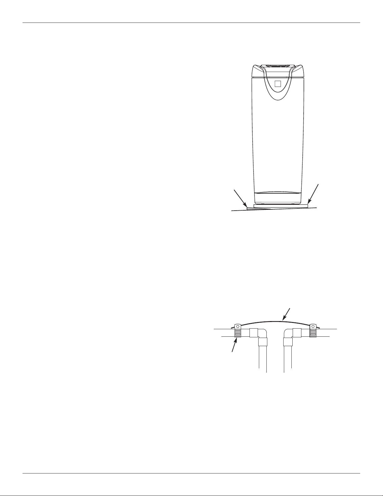
Step 2. Move the Whole Home Water
Filtration System into Place
1. Move the Whole Home Water Filtration System into
installation position. Set it on a level surface. If
needed, place the unit on a section of plywood, a
minimum of 5/8” thick. Then place shims under the
plywood to level the Whole Home Water Filtration
System (see Figure 8).
Step 3. Complete Inlet and Outlet
Plumbing
Measure, cut, and loosely assemble pipe and fittings
from the main water pipe to the inlet and outlet ports of
the Water Filtration System valve. Be sure to keep fit-
tings fully together, and pipes squared and straight.
Be sure untreated water supply pipe goes to the Water
Filtration System valve inlet side.
NOTE: Inlet and outlet are marked on the Water
Filtration System valve. Trace the water flow
direction to be sure untreated water is to inlet.
IMPORTANT: Be sure to fit, align and support all
plumbing to prevent putting stress on
the Water Filtration System valve inlet
and outlet. Undue stress from mis-
aligned or unsupported plumbing may
cause damage to the valve.
Complete the inlet and outlet plumbing for the type of
pipes you will be using.
Step 4. Cold Water Pipe Grounding
CAUTION: The house cold water pipe (metal only)
is often used as a ground for the house
electrical system, The 3-valve bypass
type of installation, shown in Figure 6,
will maintain ground continuity. If you
use a plastic bypass valve at the unit,
continuity is broken. To restore the
ground, do the following:
FIG. 8
Plywood
Shim(s)
Level if Necessary
1. Install a #4 copper wire across the removed section
of main water pipe, securely clamping it at both
ends (See Figure 9) - parts not included.
NOTE: Check local plumbing and electrical codes
for proper installation of the ground wire.
The installation must conform to them. In
Massachusetts, plumbing codes of
Massachusetts shall be conformed to.
Consult with your licensed plumber.
Morton
®
Installation & Operation Manual 11
Installation Instructions
Step 5. Install Valve Drain Hose
NOTE: See valve drain options on page 8.
1. Measure, cut to needed length and connect the 3/8"
drain line (provided) to the Whole Home Water
Filtration System valve drain fitting (See Figure 10).
Use a hose clamp to hold the hose in place.
IMPORTANT: If codes require a rigid drain line see
“Valve Drain requirements" section.
2. Run the drain hose or copper tubing to the floor
drain. Secure drain hose. This will prevent the
drain line from “whipping'' during Clean Rinse
cycles. See “Air Gap Requirements" section.
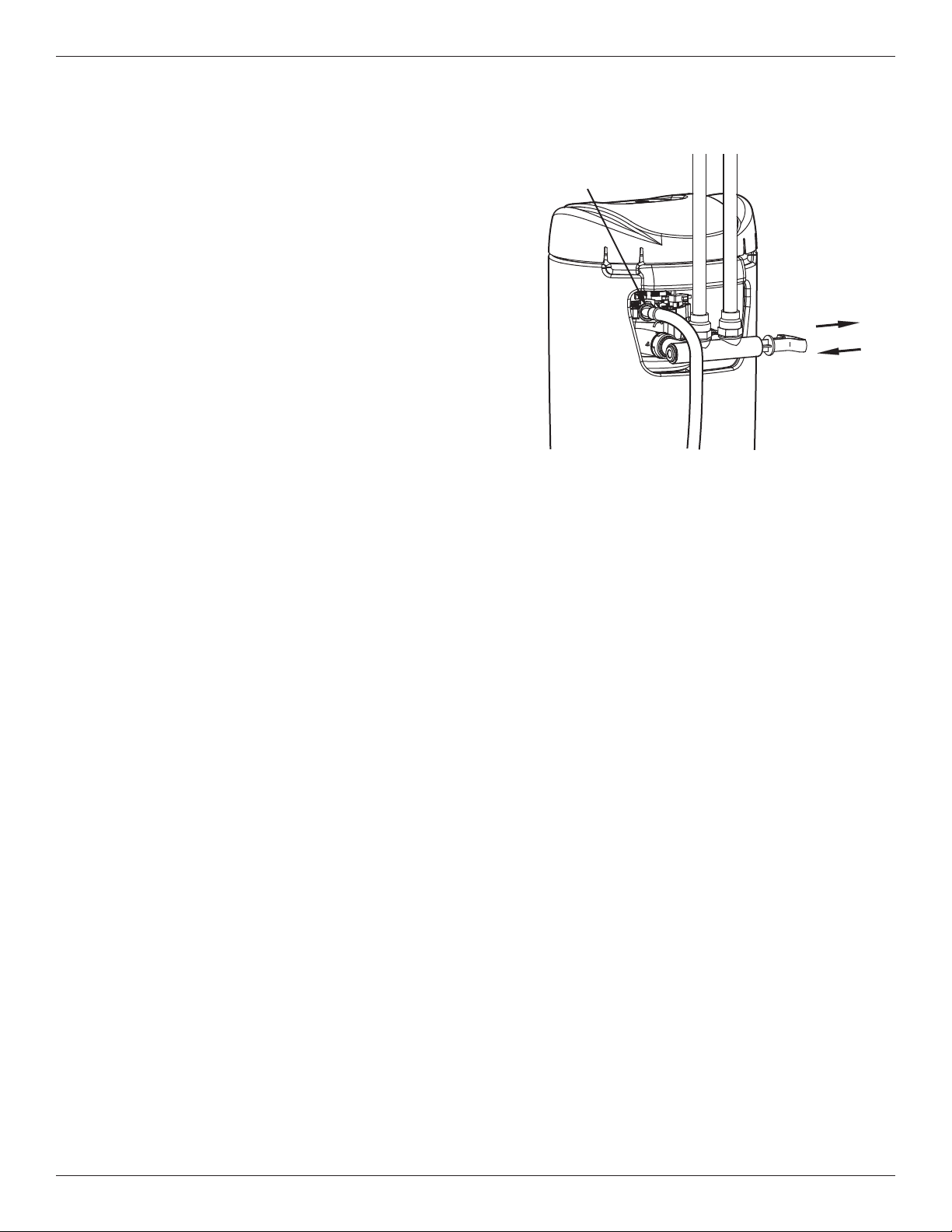
Step 6. Test for Leaks
1. Make sure the single bypass valve (or 3 valve
bypass, if installed) is in the bypass position, with
the handle pushed in (See Figure 10).
2. Fully open the main water supply valve.
3. Briefly open a faucet in the house to refill the plumb-
ing with water.
4. Slowly move the bypass valve(s) to the normal
operation position, pausing several times to allow
the unit to pressurize slowly (See Figure 10).
5. Check for leaks at all the plumbing connections you
made.
IMPORTANT: Start up procedure must be run prior to
using any filtered water. Follow the
instructions below and on Page 13.
Step 7. Turn On the Whole Home
Water Filtration System
During installation, the Whole Home Water Filtration
System wiring may be moved or jostled from place.
Check to be sure all leadwire connectors are secure
on the back of the electronic board and be sure all
wiring is away from the valve gear and motor area,
which rotates during Clean Rinse cycles.
1. Plug the Whole Home Water Filtration System’s
power supply into an electrical outlet that is not con-
trolled by a switch.
2. In the display, the words “PRESENT TIME” appear
and 12:00 PM begins to flash. Set the clock accord-
ing to the “Set Time of Day” section on Page 12.
3. Run the start up procedure, as detailed on Page 13.
Single Bypass Valve
Pull handle
OUT for normal
operation
Push handle IN
for BYPASS
Drain Line
Connection
FIG. 10
12 Morton
®
Installation & Operation Manual
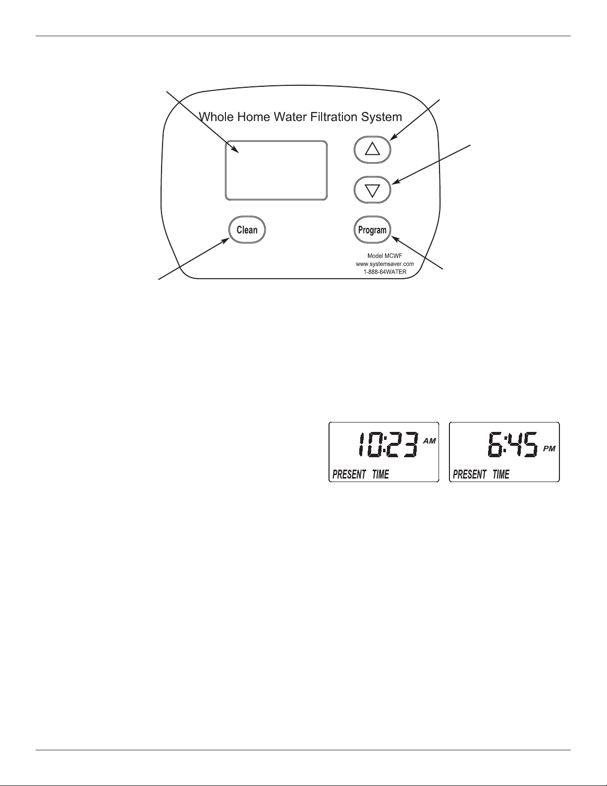
Programming the Whole Home Water Filtration System
When the power supply is plugged into the electrical
outlet, a model code and a test number (example:
J2.0), begin to flash in the faceplate display. Then,
12:00 PM and the words “PRESENT TIME" begin to
flash.
NOTE: If “- - - -” shows in the display, press the
r
UP or s DOWN button until the model code
“CF 8” shows in the display. Then, press the
PROGRAM button to set, and change to the
flashing “PRESENT TIME" display.
FIG. 11
UP
button
DOWN
button
Display
CLEAN
button
PROGRAM
button
NOTE: Press buttons and quickly release to slowly
advance the display. Hold the buttons down
for fast advance.
2. Press the PROGRAM button a few times, until the
time appears on the display, but is not flashing.
FIG. 12
Set Time of Day
If the words “PRESENT TIME" do not show in the dis-
play, press the PROGRAM button until they do.
1. Press the
r UP or s DOWN buttons to set the
present time. Up moves the display ahead; down
sets the time back. Be sure AM or PM is correct.
Questions? Call Toll Free 1-888-64 WATER (1-888-649-2837)
or visit
www.mortonwatersofteners.com
When you call, please be prepared to provide the model and serial number,
located on the rating decal on back of the cover.

Morton
®
Installation & Operation Manual 13
Start Up Procedure
IMPORTANT:
Run the start up cycle immediately after
completing installation, before using any
water in the home.
The filtration media in this Whole Home Water
Filtration System contains a small number of harmless
activated carbon particles generated during shipping
that are small enough to exit the system with water
flow. It is normal for these particles to cause a tempo-
rary discoloration of the water coming out of the sys-
tem. To avoid discolored water at your home’s faucets
the system’s start up cycle should be initiated to rinse
the particles and any discolored water down the drain.
If the Whole Home Water Filtration System is used
without first running the start up cycle, you will notice
that the water will temporarily have a gray color until
the particles have exited the system.
To Initiate the start up cycle:
1. Make sure the drain hose is attached to the Whole
Home Water Filtration System and the other end is
secured over a drain (see “Install Valve Drain Hose”
on Page 11).
2. Make sure bypass valve is in the “service” (open or
filtered water) position and the home’s water supply
is turned on.
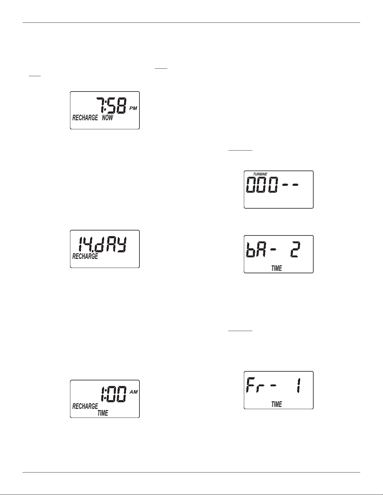
3. Press and hold the CLEAN button to initiate the
start up cycle. The button can be released when
you hear the valve changing position and
“RECHARGE NOW” flashes in the display.
During the start up cycle:
Throughout the start up cycle you will hear the valve
changing position and notice the flow of water to drain
starting and stopping. The start up cycle will take
approximately 20 minutes. Avoid using water during
this time. Do not set the time of day or press other
buttons during the start up cycle, as this will interrupt
the start up cycle. Do not unplug the power supply
during the start up cycle. If the start up cycle is inter-
rupted, it should be initiated again and allowed to run
to completion.
After the start up cycle:
Once the start up procedure completes successfully, it
cannot be initiated a second time. The Whole Home
Water Filtration System will automatically return to the
normal operation position. Once the start up cycle has
run, a faucet in the home should be opened and water
allowed to run for 10 minutes at the system’s rated
flow. If, after running the start up cycle, the water still
appears discolored, manually run Clean Rinse cycles
(See Page 14) until the water is clear.
If the time of day was not set before the start up cycle,
set it now (See Page 12).
Check the new plumbing connections and joints once
more for leaks.
Questions? Call Toll Free 1-888-64 WATER (1-888-649-2837)
or visit
www.mortonwatersofteners.com
When you call, please be prepared to provide the model and serial number,
located on the rating decal on back of the cover.
14 Morton
®
Installation & Operation Manual
Customizing Features / Options
Set Number of Days Between Clean
Rinse Cycles
By default the Whole Home Water Filtration System
will automatically initiate a Clean Rinse every 14
days. This should be sufficient for most applications.
To change the number of days between Clean Rinse
cycles:
1. Press the PROGRAM button twice, so “RECHARGE”
is shown in the display.
2. Press the
r UP or s DOWN buttons to set the
number of days between Clean Rinse cycles (from 1
to 99).
3. Press the PROGRAM button twice when complete.
Set Clean Rinse Time
By default the Whole Home Water Filtration System
will Clean Rinse at 1:00 a.m.
To change the Clean Rinse start time:
1. Press the PROGRAM button three times, so
“RECHARGE TIME” is shown in the display.
FIG. 14
2. Press the r UP or s DOWN buttons to set the
Clean Rinse time. Be sure AM or PM is correct.
3. Press the PROGRAM button again when com-
plete.
FIG. 15
Set Length of Clean Rinse
By default the Whole Home Water Filtration System’s
Clean Rinse cycle will consist of a 2 minute back-
wash followed by a 1 minute fast rinse. This should
be sufficient for most applications.
Increasing the length of Clean Rinse time will
increase the amount of water flushed to drain during
each Clean Rinse cycle, therefore, these times
should only be increased when necessary.
To change the length of the backwash part of the
Clean Rinse cycle:
1. Press and hold
the PROGRAM button for a few
seconds, until the “000 - -” screen appears, as shown
in Figure 16.
2. Press the PROGRAM button once, so “bA TIME”
appears in the display.
FIG. 16
3. Press the r UP or s DOWN buttons to set the
length of backwash in minutes.
4. Press the PROGRAM button twice when complete.
To change the length of the fast rinse part of the
Clean Rinse cycle:
1. Press and hold
the PROGRAM button for a few
seconds, until the “000 - -” screen appears, as shown
in Figure 16.
2. Press the PROGRAM button twice, so “Fr TIME”
appears in the display.
3. Press the
r UP or s DOWN buttons to set the
length of fast rinse in minutes.
4. Press the PROGRAM button again when com-
plete.
FIG. 17
FIG. 18
FIG. 13
Start a Clean Rinse Cycle
To manually start a Clean Rinse cycle, press and
hold the CLEAN button for a few seconds, until
“RECHARGE NOW” flashes in the display.
Morton
®
Installation & Operation Manual 15
Customizing Features / Options
Operating in Manual Clean Rinse
Mode
Clean Rinse cycles will run automatically, unless the
automatic Clean Rinse function has been disabled. If
this function has been disabled, it will be necessary to
manually initiate any Clean Rinse cycles. It is recom-
mended that a Clean Rinse cycle should be run at
least once each month, or more frequently if neces-
sary.
A manual Clean Rinse mode may be used when a
drain (required for automatic Clean Rinse) is not
available. However, it is recommended that automat-
ic Clean Rinse be used if the drain requirements can
be met.
IMPORTANT: During the Clean Rinse cycle, whether
manually or automatically initiated, water will flow
from the valve drain port. If a permanent drain line
has not been installed, provisions must be made for
the drain flow prior to initiating a Clean Rinse cycle.
DISABLING AUTOMATIC CLEAN RINSE
To disable the automatic Clean Rinse function:
1. Press and immediately release the CLEAN button
(pressing and holding the button a few seconds would
initiate a Clean Rinse cycle).
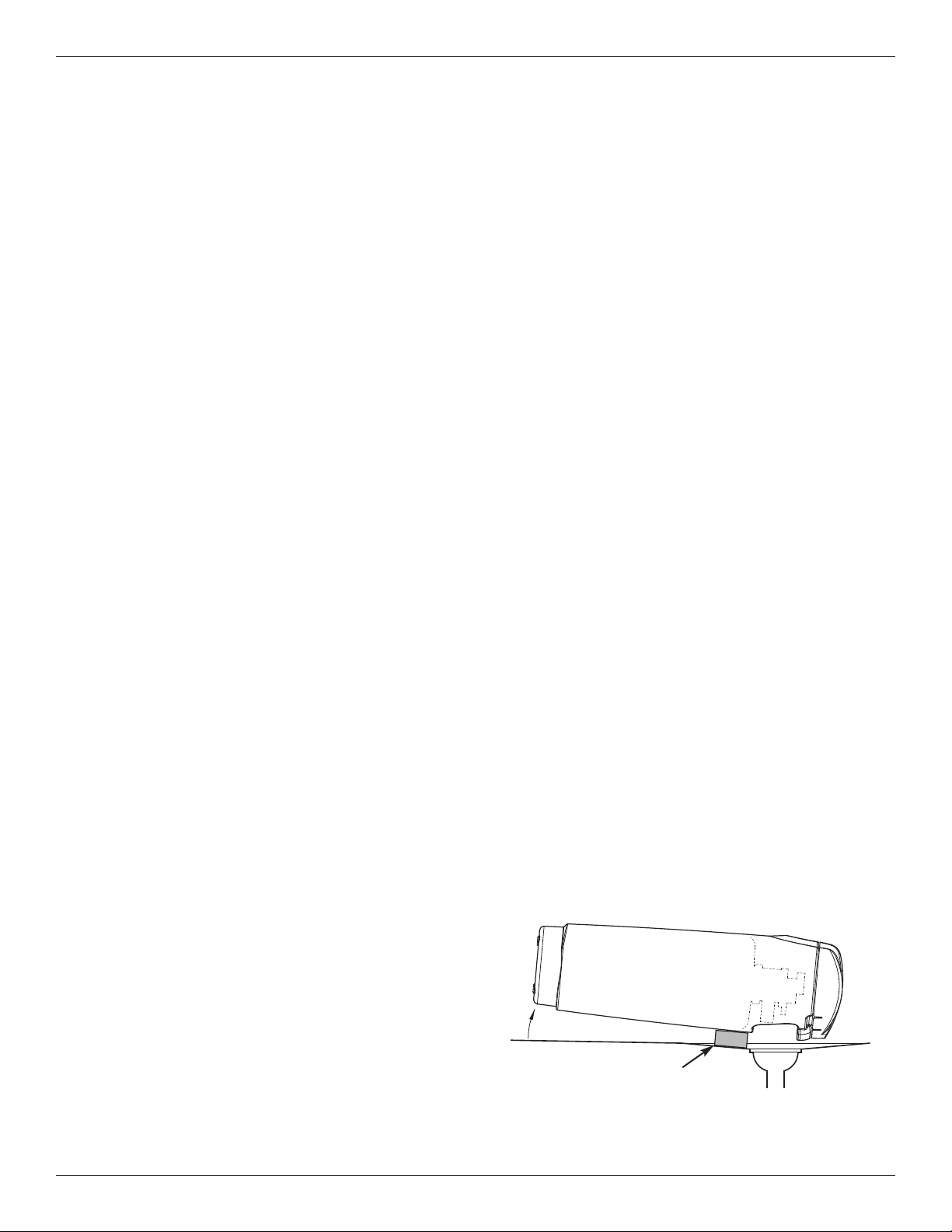
2. “VAC” should flash in the display, as shown in
Figure 19, indicating that the Whole Home Water
Filtration System is in the manual Clean Rinse mode
(the automatic Clean Rinse function has been dis-
abled).
Power Outage Memory
If electrical power to the Whole Home Water Filtration
System is lost, “memory'' built into the controller cir-
cuitry will keep all settings for several hours. While
the power is out, the display is blank and the Whole
Home Water Filtration System will not Clean Rinse.
When electrical power is restored, you have to reset
the time of day only if the display is flashing. The
Clean Rinse TIME never requires resetting unless a
change is desired. Even if the clock is incorrect after
a long power outage, the Whole Home Water
Filtration System works as it should to keep your
water treated. However, Clean Rinse cycles may
occur at the wrong time of day until you reset the
clock to the correct time of day.
NOTE: If the Whole Home Water Filtration System
was in a Clean Rinse cycle when power was
lost, it will now finish the cycle.
MANUALLY STARTING A CLEAN RINSE CYCLE
To manually start a Clean Rinse cycle:
1. Press and hold
the CLEAN button for a few sec-
onds, until “RECHARGE NOW” flashes in the display,
as shown in Figure 20.
2. When the Clean Rinse cycle is complete, the
Whole Home Water Filtration System will remain in
the manual Clean Rinse mode.
FIG. 19
FIG. 20
RE-ENABLING AUTOMATIC CLEAN RINSE
To return the Whole Home Water Filtration System to
its automatic Clean Rinse function:
1. Press and immediately release the CLEAN button.
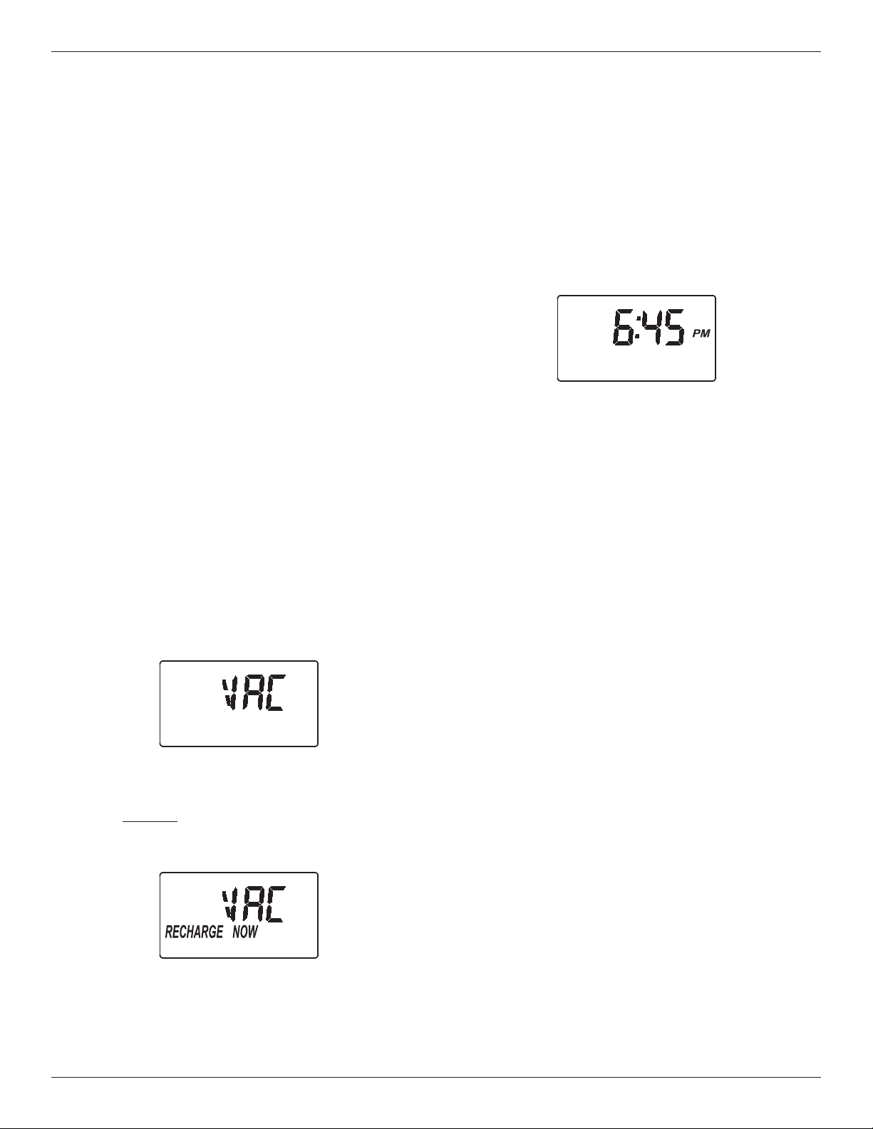
2. The flashing “VAC” on the display should be
replaced by the normal time of day screen, as shown
in Figure 21.
FIG. 21
16 Morton
®
Installation & Operation Manual
Care of Your Whole Home Water Filtration System
Vacations and Extended Periods of
No Water Use
If your Whole Home Water Filtration System will not be
used for an extended period of time (several months),
please follow one of these recommendations:
= If the water supply to the unit is not turned off, and
the automatic Clean Rinse function has not been
disabled, then no further actions are required.
= If the Clean Rinse cycle cannot be automatically
run, due to the water supply being shut off, the
power supply being unplugged or the automatic
Clean Rinse function being disabled, then it is rec-
ommended that a minimum of 2 manually initiated
Clean Rinse cycles be performed when the system
is placed back into operation (see Start a Clean
Rinse Cycle section on Page 14).
= In any installation where there is a possibility of
freezing, the Whole Home Water Filtration System
should be disconnected and the water drained (see
Protect the Whole Home Water Filtration System
from Freezing section).
Protect the Whole Home Water
Filtration System from Freezing
If the Whole Home Water Filtration System is installed
where it could freeze (summer cabin, lake home, etc.),
you must drain all water from it to stop possible freeze
damage. To drain the unit:
1. Close the shut-off valve on the house main water
pipe, near the water meter or pressure tank.
2. Open a faucet in the filtered water pipes to vent
pressure in the unit.
3. Move the stem in the single bypass valve to bypass.
Close the inlet and outlet valve in a 3 valve bypass
system, and open the bypass valve. If you want
water in the house pipes again, reopen the shut-off
valve on the main water pipe.
4. Unplug the power supply at the wall outlet. Remove
the cover. Take off the drain hose if it will interfere
with moving the Whole Home Water Filtration
System into position over the drain.
5. Remove the large holding clips at the Whole Home
Water Filtration System inlet and outlet. Separate
the unit from the bypass valve.
6. Lay a piece of 2 inch thick board near the floor
drain.
7. Move the Whole Home Water Filtration System
close to the drain. Slowly and gently, tip it over until
the rim rests on the wood block with the inlet and
outlet over the drain. Do not allow the unit’s weight
to rest on the inlet and outlet fittings or they may
break.
8. Tip the bottom of the Whole Home Water Filtration
System up a few inches and hold until all water has
drained. Leave the unit laying like this until you are
ready to use it. Plug the inlet and outlet with clean
rags to keep dirt, bugs, etc. out.
FIG. 22
Drain all Water from Whole Home
Water Filtration System
Floor Drain
Wood Block
Morton
®
Installation & Operation Manual 17
Troubleshooting
PROBLEM CAUSE CORRECTION
Water has black or
gray color
(NEW SYSTEM) Start up procedure
has not been completed
Run start up procedure (See Page 13) or run
consecutive Clean Rinse cycles (See Page 14)
until water color returns to normal.
(NOT A NEW SYSTEM) Normal abra-
sion of filtration media
Manually initiate a Clean Rinse cycle (See Page 14).
Low water pressure at
house faucets
Sediment filter screen is clogged Manually initiate a Clean Rinse cycle (See Page 14).
If the filter screen is frequently plugging, it may be
necessary to adjust the frequency of Clean Rinse
cycles or add a sediment filter upstream (See
Figure 3 on Page 7).
Filtration media pores are blocked Manually initiate a Clean Rinse cycle (See Page 14).
If the filtration media pores are frequently block-
ing, it may be necessary to increase the frequen-
cy of Clean Rinse cycles.
Water has objection-
able taste and/or odor
System is in bypass Move bypass valve(s) to normal operating (non-
bypass) position.
Filtration media pores are blocked Manually initiate a Clean Rinse cycle (See Page 14).
If the filtration media pores are frequently block-
ing, it may be necessary to increase the frequen-
cy of Clean Rinse cycles.
No water flow to drain
during Clean Rinse
cycle
System is in bypass Move bypass valve(s) to normal operating (non-
bypass) position.
Drain flow control is plugged Clean drain flow control (See Page 18).
Drain hose is plugged or kinked Straighten drain hose.
Power supply is unplugged from wall
electrical outlet (display will be blank)
Check for loss of power and correct.
Clean Rinse cycle does
not run automatically
If display reads “VAC”, then Clean
Rinse function has been disabled
Press and release the CLEAN button until display
no longer reads “VAC”.
If display is blank, power supply may be
unplugged from wall electrical outlet
Check for loss of power.
Clean Rinse cycle does
not run at the pro-
grammed time of day
If time display is flashing, then a long
power loss caused the clock to lose its
time setting
Reset the clock to the correct time of day (See
Page 12).
Steady beeping from
electronic control
Electronic control board is wet Allow 48 hours for board to dry, or use blow dryer.
Error Code E1, E3 or
E4 appears
Fault in wiring harness or connections
to position switch
Replace wiring harness or connection to position
switch (See parts list at end of this manual).
Fault in switch Replace switch (See parts list at end of this manual).
Fault in valve causing high torque Replace rotor/seal kit (instructions included with kit).
Motor inoperative Replace motor (instructions included with motor)
Error Code E5 appears Electronic control Replace electronic control board (PWA) (instruc-
tions included with PWA).
Need help troubleshooting? Call Toll Free 1-888-64 WATER (1-888-649-2837)
or visit
www.mortonwatersofteners.com
When you call, please be prepared to provide the model and serial number,
located on the rating decal on back of the cover.
18 Morton
®
Installation & Operation Manual
Troubleshooting
Resetting to Factory Defaults
To reset the electronic controller to its factory default
for all settings (time, number of days between Clean
Rinse cycles, etc.):
1. Press the PROGRAM button and hold it until the
display changes twice to show “CODE” and the
flashing model code.
2. Press the
r UP button twice to display a flashing
“SoS”.
3. Press the PROGRAM button, and the electronic
controller will restart.
4. Set the present time, as described on page 12.
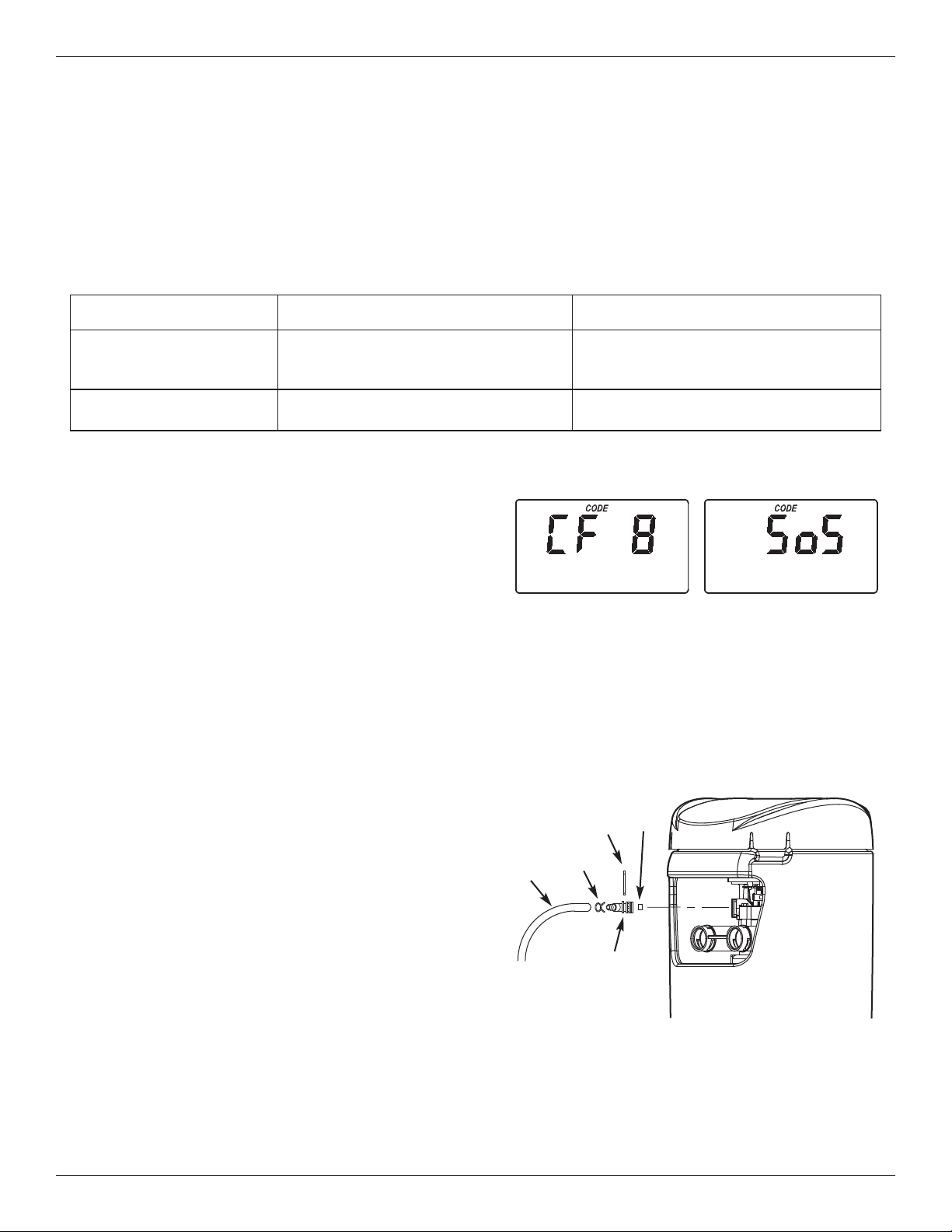
Cleaning the Drain Flow Control
This procedure is not required if the Whole Home
Water Filtration System is operating normally. It
should be performed only if a problem with lack of
water flow to drain is encountered, as detailed in the
troubleshooting table on Page 17.
1. Remove the clip holding the drain fitting into the
valve (See Figure 24).
2. Remove the drain fitting from the valve
3. Clear any obstruction.
4. Reinstall the drain fitting into the valve.
5. Reinstall the clip to secure the drain fitting in the
valve.
PROBLEM CAUSE CORRECTION
Water running to the
drain (while unit is not in
the Clean Rinse cycle)
Inner valve defect causing leak Replace seals and rotor
Filter media in household
plumbing
Crack in distributor or riser tube Replace distributor or riser tube.
Procedure for removing error code from display:
1. Unplug power supply from electrical outlet.
2. Correct problem.
3. Plug power supply back in.
4. Wait 8 minutes. The error code will return if the problem was not corrected.
Assistance from customer service may be needed with the following:
FIG. 23
FIG. 24
Removing Drain Fitting to
Clean Flow Control
Clip
Hose
Clamp
Drain
Hose
Flow
Control
Drain
Fitting
Need help troubleshooting? Call Toll Free 1-888-64 WATER (1-888-649-2837)
or visit
www.mortonwatersofteners.com
When you call, please be prepared to provide the model and serial number,
located on the rating decal on back of the cover.

Morton
®
Installation & Operation Manual 19
Notes
20 Morton
®
Installation & Operation Manual
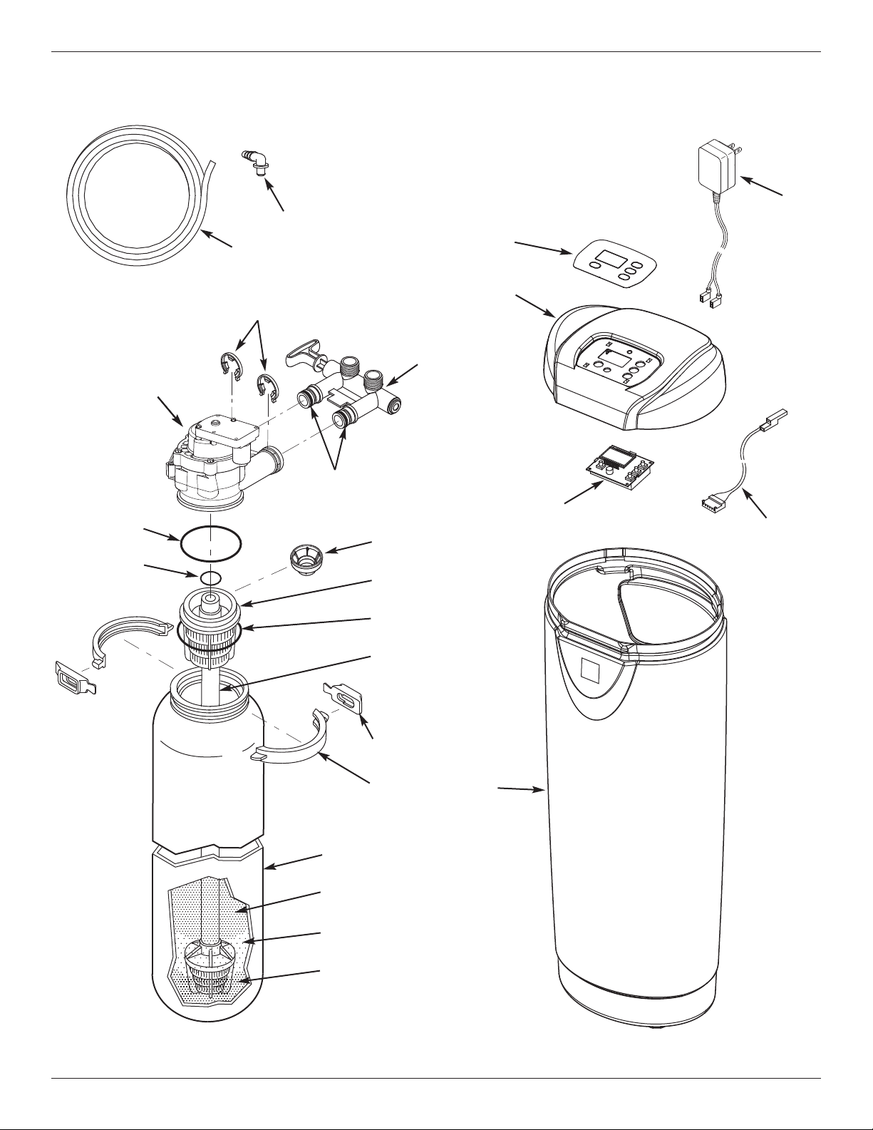
Whole Home Water Filtration System Exploded View
1
2
4
3
6
8
7
11
10
9
12
14
17
16
13
18
15
5
20
19
Valve Assembly
See Pages 22 & 23
for parts
70
71
72
Morton
®
Installation & Operation Manual 21
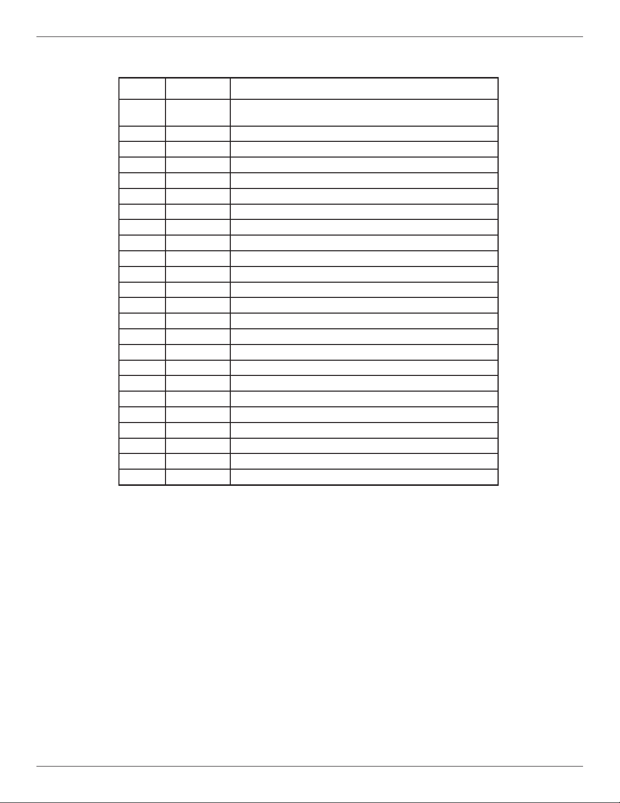
Whole Home Water Filtration System Parts List
Key No. Part No. Description
¢
7311038
Assembly, Replacement Mineral Tank, w/media & asso-
ciated components (Includes Key Nos. 1 through 13)
– 7112963 Distributor O-Ring Kit (includes Key Nos. 1-3)
1
á
O-Ring, 2-7/8” x 3-1/4”
2
á
O-Ring, 13/16” x 1-1/16”
3
á
O-Ring, 2-3/4” x 3”
4 7077870 Top Distributor
5 7265025 Filter Screen
6 7105047 Repl. Bottom Distributor
– 7331177 Tank Neck Clamp Kit (includes 2 ea. of Key Nos. 7 & 8)
7
á
Retainer Clip (2 req.)
8
á
Clamp Section (2 req.)
9
Ù
Mineral Tank, 8” x 25”
10
Ù
Activated Carbon, 10 lbs.
11
Ù
Filter Sand, 5 lbs.
12
Ù
Gravel, 6 lbs.
13
Ù
Outer Shroud Tank, with Morton Badge
14 7310781 Faceplate Decal
15 7310773 Cover (order decal above)
16 7311020 Repl. Electronic Control Board (PWA)
17 7351054 Power Supply, 24V DC
18 7259927 Wire Harness
19 7139999 Drain Hose
20 1103200 Adaptor Elbow
¢
7387186 Owner’s Manual
¢ Not illustrated.
Ù Mineral Tank and media can only be purchased as part of the Replacement Mineral
Tank Assembly (See top of list).
Questions? Call Toll Free 1-888-64 WATER (1-888-649-2837)
or visit
www.mortonwatersofteners.com
When you call, please be prepared to provide the model and serial number,
located on the rating decal on back of the cover.
To order repair parts call toll free 1-888-649-2837.
Manufactured and warranted by
Water Channel Partners
1890 Woodlane Drive
Woodbury, MN 55125
22 Morton
®
Installation & Operation Manual
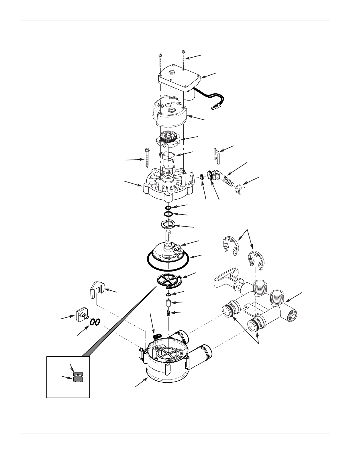
Valve Assembly Exploded View
50
52
53
51
55
56
59
58
57
60
61
66
67
62
63
64
68
69
73
65
74
75
Wear Strip
Seal
Cross-section
View
77
78
54
76
70
71
72
Morton
®
Installation & Operation Manual 23
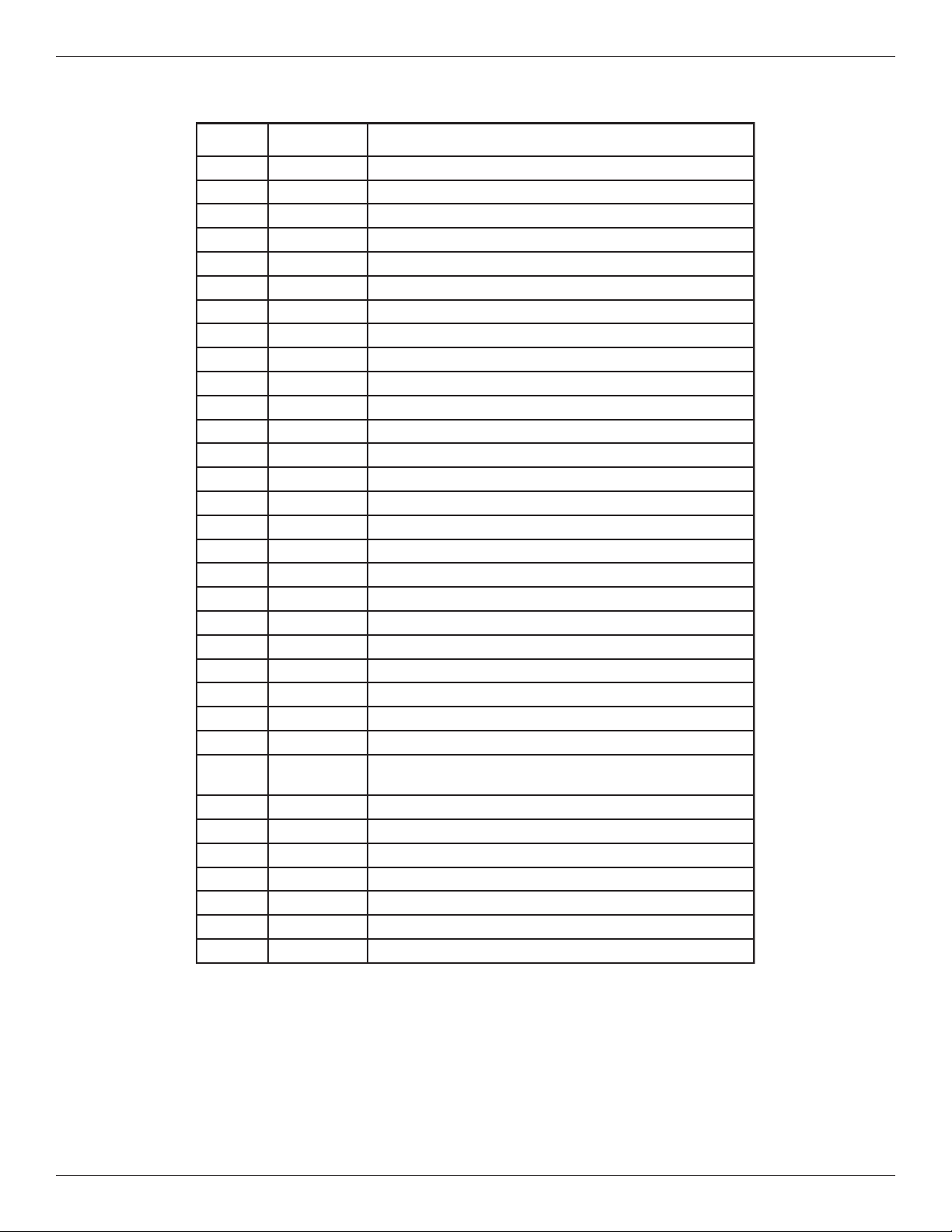
Valve Parts List
Key No. Part No. Description
– 7384683 Motor, Cam & Gear Kit, 3/4” (incl. Key Nos. 50-52)
50
á
Motor
51
á
Cam & Gear
52 7338111 Screw, #6-19 x 1-3/8” (2 req.)
53 7337474 Motor Mount
54 7030713 Switch
– 7331274 Drain Hose Adaptor Kit (includes Key Nos. 55-59)
55
á
Clip, Drain
56
á
Adaptor, Drain Hose
57
á
Hose Clamp
58
á
O-Ring, 5/8” x 13/16”
59
á
Flow Plug, 3.4 gpm
– 7129716 Seal Kit (includes Key Nos. 60-65)
60
á
O-Ring, 7/16” x 5/8”
61
á
O-Ring, 3/4” x 15/16”
62
á
O-Ring, 3-3/8” x 3-5/8”
63
á
Rotor Seal
64
á
O-Ring, 3/8” x 9/16”
65
á
Seal, Nozzle & Venturi
66 7082087 Wave Washer
67 7199232 Rotor & Disc
– 7342665 Drain Plug Kit, 3/4” (includes Key Nos. 64, 68 & 69)
68
á
Plug, Drain Seal
69
á
Spring
70 7337563 Clip, 3/4”, pack of 4
71 7370286
Bypass Valve Assembly, 3/4”, in cluding 2 O-Rings
(See Key No. 72)
72 7337571 O-Ring, 15/16” x 1-3/16”, pack of 4
73 7082053 Valve Body
74 7081201 Retainer, Nozzle & Venturi
75 7342649 O-Ring, 1/4” x 3/8”, pack of 2
76 7100940 Plug, Aspirator Port
77 7337466 Valve Cover
78 7342657 Screw, #10-14 x 2”, pack of 5
Questions? Call Toll Free 1-888-64 WATER (1-888-649-2837)
or visit
www.mortonwatersofteners.com
When you call, please be prepared to provide the model and serial number,
located on the rating decal on back of the cover.
To order repair parts call toll free 1-888-649-2837.
Manufactured and warranted by
Water Channel Partners
1890 Woodlane Drive
Woodbury, MN 55125