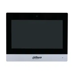

IP Indoor Monitor
User’s Manual
V1.0.0
I
Foreword
General
This document mainly introduces structure, installation process, and basic configuration of the IP
Indoor Monitor (hereinafter referred to as the "indoor monitor").
Safety Instructions
The following categorized signal words with defined meaning might appear in the manual.
Signal Words Meaning
CAUTION
Indicates a potential risk which, if not avoided, could result in property
damage, data loss, lower performance, or unpredictable result.
NOTE
Provides additional information as the emphasis and supplement to the
text.
Revision History
Version Revision Content Release Date
V1.0.0 First release April 2020
About the Manual
The manual is for reference only. If there is inconsistency between the manual and the actual
product, the actual product shall prevail.
We are not liable for any loss caused by the operations that do not comply with the manual.
The manual would be updated according to the latest laws and regulations of related regions.
For detailed information, see the paper manual, CD-ROM, QR code or our official website. If
there is inconsistency between paper manual and the electronic version, the electronic version
shall prevail.
All the designs and software are subject to change without prior written notice. The product
updates might cause some differences between the actual product and the manual. Please
contact the customer service for the latest program and supplementary documentation.
There still might be deviation in technical data, functions and operations description, or errors
in print. If there is any doubt or dispute, please refer to our final explanation.
Upgrade the reader software or try other mainstream reader software if the manual (in PDF
format) cannot be opened.
All trademarks, registered trademarks and the company names in the manual are the properties
of their respective owners.
Please visit our website, contact the supplier or customer service if there is any problem
occurred when using the device.
If there is any uncertainty or controversy, please refer to our final explanation.

II
Important Safeguards and Warnings
The following description is the correct application method of the device. Read the manual carefully
before use to prevent danger and property loss. Strictly conform to the manual during application
and keep it properly after reading.
Operating Requirement
Do not place and install the device in an area exposed to direct sunlight or near heat generating
device.
Do not install the device in a humid, dusty or fuliginous area.
Keep its horizontal installation, or install it at stable places, and prevent it from falling.
Do not drip or splash liquids onto the device; do not put on the device anything filled with
liquids to prevent liquids from flowing into the device.
Install the device at well-ventilated places; do not block its ventilation opening.
Use the device only within rated input and output range.
Do not dismantle the device arbitrarily.
The device shall be used with screened network cables.
Power Requirement
The product shall use electric wires (power wires) required by the region where the device will
be used.
Use power supply that meets SELV (safety extra low voltage) requirements, and supply power
with rated voltage that conforms to Limited Power Source in IEC60950-1. For specific power
supply requirements, refer to device labels.
Appliance coupler is a disconnecting device. During normal use, keep an angle that facilitates
operation.
Do not cut off power supply during device upgrade.

III
Table of Contents
Foreword ............................................................................................................................................................ I
Important Safeguards and Warnings .............................................................................................................. II
1 Introduction ................................................................................................................................................... 1
Overview ....................................................................................................................................................................................... 1
Features ......................................................................................................................................................................................... 1
Front Panel .................................................................................................................................................................................... 2
Rear Panel ..................................................................................................................................................................................... 3
Cable Connections..................................................................................................................................................................... 5
2 Installation ..................................................................................................................................................... 6
3 Network Diagram .......................................................................................................................................... 9
4 Configuration .............................................................................................................................................. 10
Configuration Process ............................................................................................................................................................ 10
VDPConfig ................................................................................................................................................................................... 10
Configuring Door Station ...................................................................................................................................................... 10
4.3.1 Initialization .................................................................................................................................................................. 10
4.3.2 Configuring VTO Number ........................................................................................................................................ 11
4.3.3 Configuring Network Parameters ......................................................................................................................... 12
4.3.4 Selecting SIP Servers ................................................................................................................................................. 13
4.3.5 Adding VTO Devices .................................................................................................................................................. 15
4.3.6 Adding Room Number .............................................................................................................................................. 16
Configuring Indoor Monitor ................................................................................................................................................ 17
4.4.1 Initialization .................................................................................................................................................................. 18
4.4.2 Network Settings ........................................................................................................................................................ 24
4.4.3 Project Settings ............................................................................................................................................................ 27
4.4.4 General Settings .......................................................................................................................................................... 33
Alarm ............................................................................................................................................................................................ 38
4.5.1 Alarm Record ................................................................................................................................................................ 38
4.5.2 Alarm Settings .............................................................................................................................................................. 39
4.5.3 Alarm Mode .................................................................................................................................................................. 43
Unlocking .................................................................................................................................................................................... 44
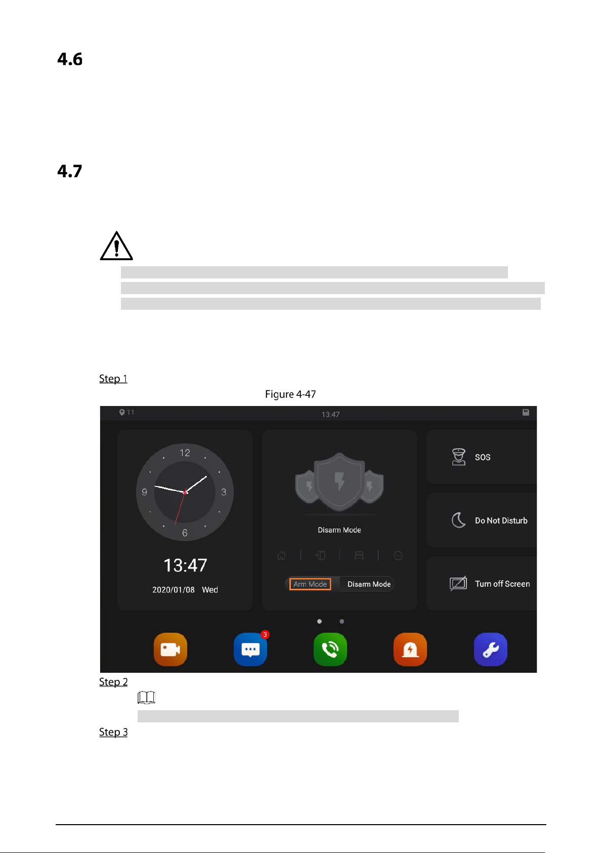
Arm/Disarm ................................................................................................................................................................................ 44
4.7.1 Arm ................................................................................................................................................................................... 44
4.7.2 Disarm ............................................................................................................................................................................. 45
Elevator Control ........................................................................................................................................................................ 45
Commissioning ......................................................................................................................................................................... 45
4.9.1 Watching Monitoring Videos .................................................................................................................................. 45
4.9.2 Checking Messages .................................................................................................................................................... 47
4.9.3 Making Calls .................................................................................................................................................................. 49
Cybersecurity Recommendations ............................................................................................. 51

1
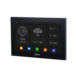
1 Introduction
Overview
The 10-inch IP indoor monitor, widely used in intelligent buildings, integrates functions of
monitoring, voice/video call, and unlock. Technologies like embedded technology, IP
communication methods, simple network management protocol (SNMP), network encryption, and
more are applied to make the whole system more stable, safer, and easier to be managed.
Features
Wi-Fi: Provides wireless network for devices.
Voice call: You can make calls on the door stations to indoor monitors.
Monitoring: Videos captured by fence stations, door stations, IP cameras, and more can be
watched on the indoor monitor.
Elevator control: You can make the elevator come to your floor through the indoor monitor.
Emergency call: Emergency calls can be made on the indoor monitor.
Auto snapshot: During calls, or during monitoring, images can be captured, and the images can
be stored in the SD card.
Video recording: You can record videos through the indoor monitor if SD card is inserted into
the rear panel of the indoor monitor.
Do not disturb: You can set period in which you do not want to be disturbed.
Remote unlock: You can unlock doors remotely.
Arm and disarm: You can set alarm areas, and then arm and disarm.
Record search: Call records and alarm records can be viewed.
Message check: You can check text messages and videos left by visitors, or public notices
released by the management center.
App: You can install app on your mobile phone, and then you can unlock doors, making calls,
receive alarm messages, and more through the app.
2
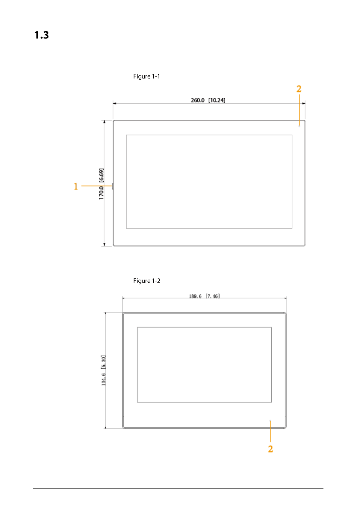
Front Panel
10 Inch
Front panel [mm (inch)]
7 Inch
Front panel [mm (inch)]
3
Table 1-1 Components
No. Name
1
On/off button. Press the button, and then you can turn on/off the screen; press and
hold the button, you can turn on/off or restart the indoor monitor.
2 MIC, inputs audio.
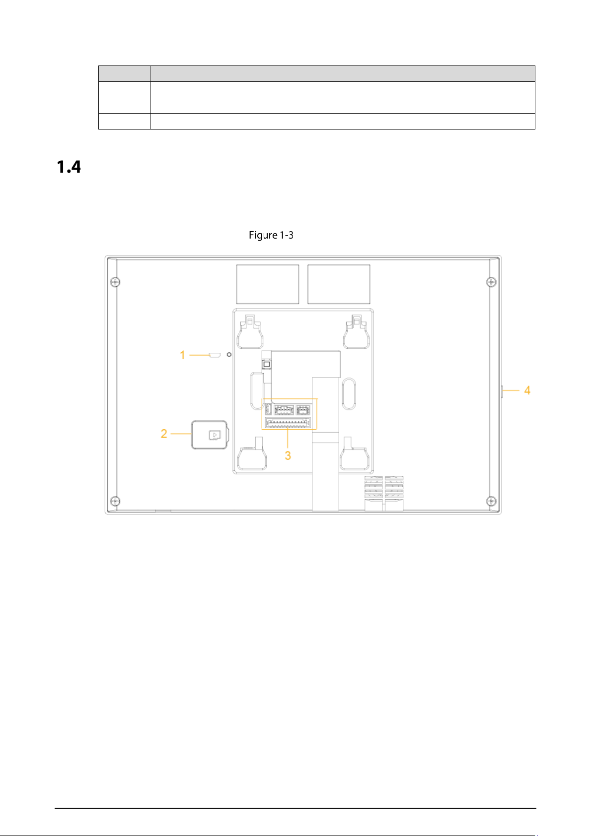
Rear Panel
10 Inch
Rear panel
4
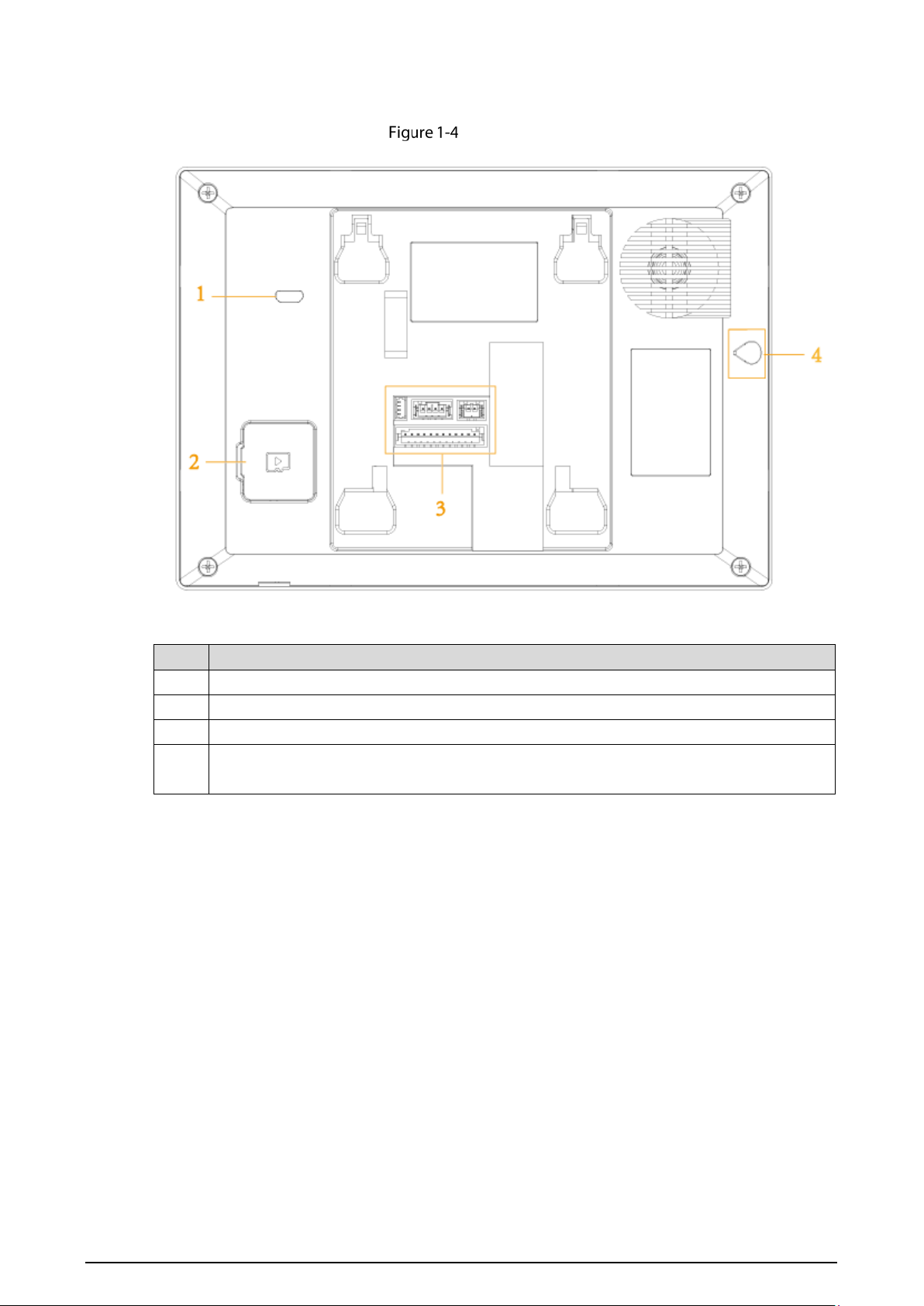
7 Inch
Rear panel
Table 1-2 Rear panel description
No. Description
1 USB port, used by project personnel.
2 SD card slot.
3 Alarm ports, power cables, RS-485 port, and network ports are under the cover.
4
On/off button. Press the button, and then you can turn on/off the screen; press and hold
the button, you can turn on/off or restart the indoor monitor.
5
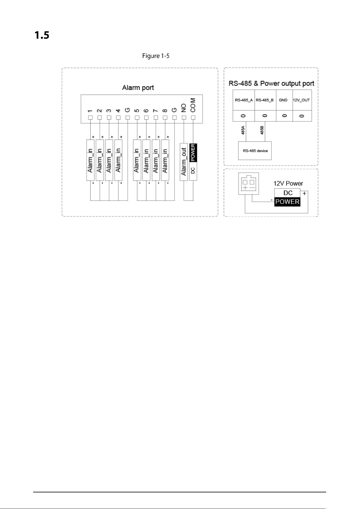
Cable Connections
Cable connection
6
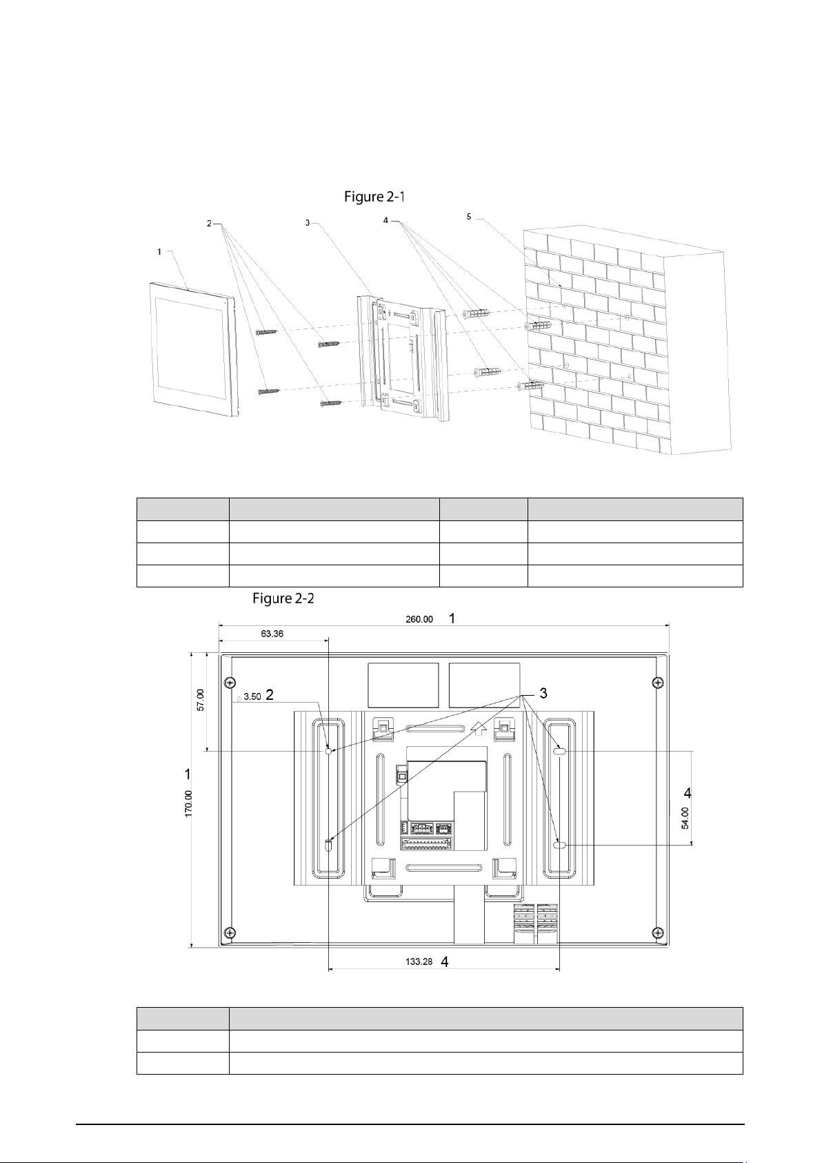
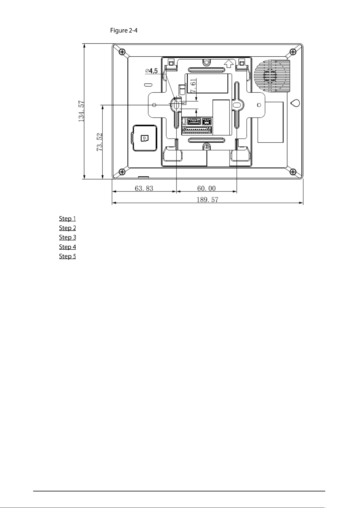
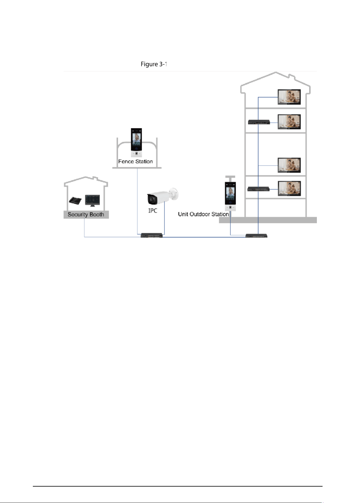
2 Installation
10 Inch
Installation
Table 2-1 Components
No. Name No. Name
1 Indoor monitor 4 Anchor bolt
2 ST3 self-tapping screws 5 Wall
3 Bracket – –
Screw hole distances and diameters [mm]
Table 2-2 Description of screw hole distances and diameters
No. Description
1 Indoor monitor dimension
2 Bracket screw hole diameter
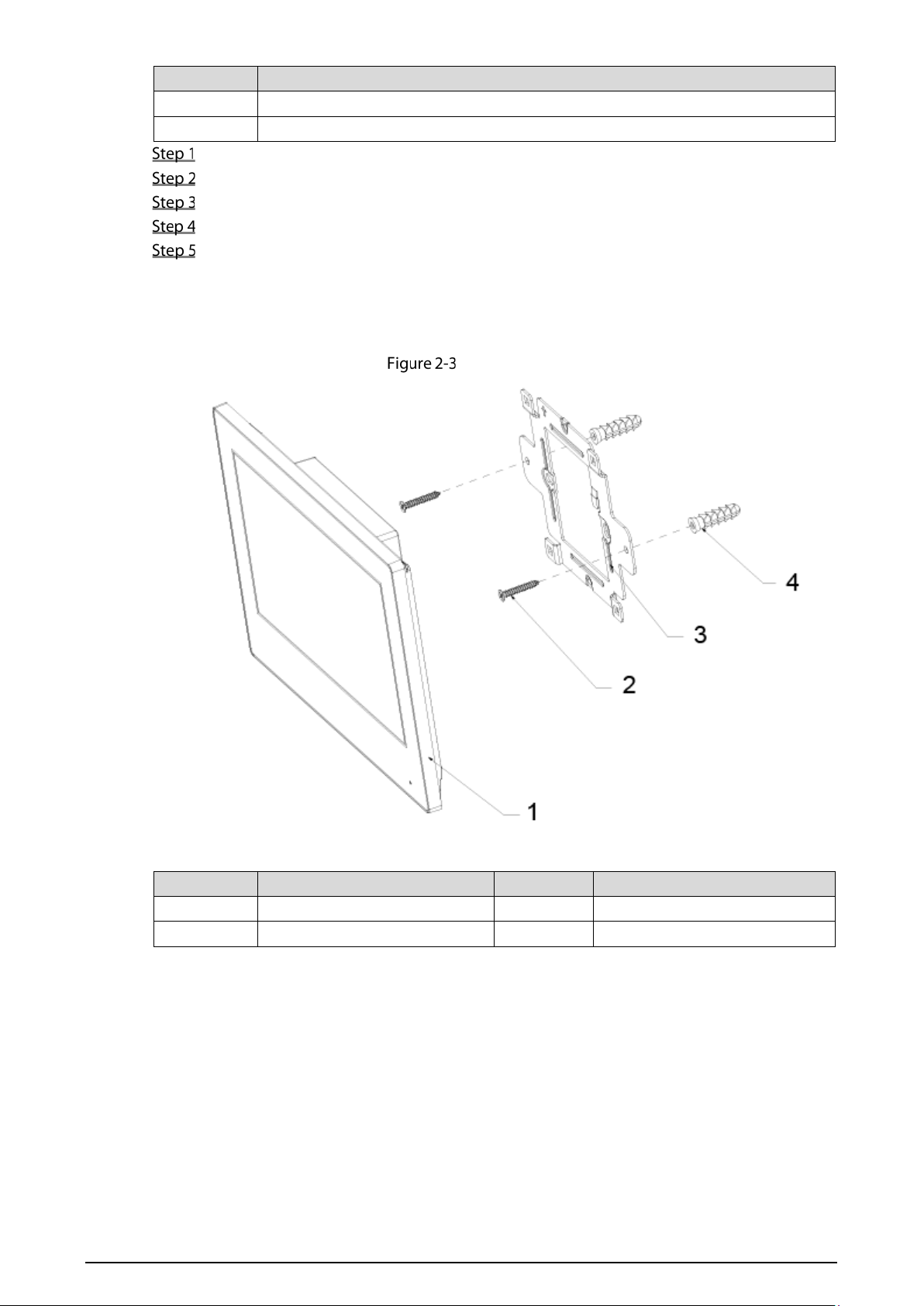
7
No. Description
3 Bracket oval hole position
4 Screw hole distance
Drill four screw holes in the wall according to holes on the bracket.
Put anchor bolts into the screw holes.
Fix the bracket on the wall with screws.
Connect cables (power cable, network cables, and more).
Hang the indoor monitor on the bracket.
The installation is completed.
7 Inch
Installation
Table 2-3 Components
No. Name No. Name
1 Indoor monitor 3 Bracket
2 Bracket fixing screws 4 Anchor bolt
8
Screw hole distances and diameters [mm]
Drill two screw holes in the wall according to holes on the bracket.
Put anchor bolts into the screw holes.
Fix the bracket on the wall with screws.
Connect cables (power cable, network cables, and more).
Hang the indoor monitor on the bracket.
The installation is completed.
9
3 Network Diagram
Network diagram

10
4 Configuration
This chapter introduces initialization, cable connection, and parameter configuration to realize basic
functions, including device management, calling, and monitoring.
Configuration Process
Before configuration, make sure that there is no short circuit or open circuit.
Plan IP address for every device, and also plan the unit number and room number you need.
Configure VTO. See "4.3 Configuring Door Station."
1) Initialize door station (VTO). See "4.3.1 Initialization."
2) Configure door station (VTO). See "4.3.2 Configuring VTO Number."
3) Configure door station (VTO) network parameters. See "4.3.3 Configuring Network
Parameters."
4) Configure SIP Server. See "4.3.4 Selecting SIP Servers."
5) Add door stations (VTO) to the SIP server. See "4.3.5 Adding VTO Devices."
6) Add room number to the SIP server. See "4.3.6 Adding Room Number."
Configure indoor monitor (VTH). See the VTH users' manual.
Commissioning. See "4.5 Commissioning."
VDPConfig
You can download the "VDPConfig" to initialize devices, change IP address and upgrade system for
multiple devices at the same time. For the detailed information, see the VDPConfig user's manual.
Configuring Door Station
Connect the door station (VTO) to your PC with network cable, and for the first-time login, you need
to create a new password for the web interface.
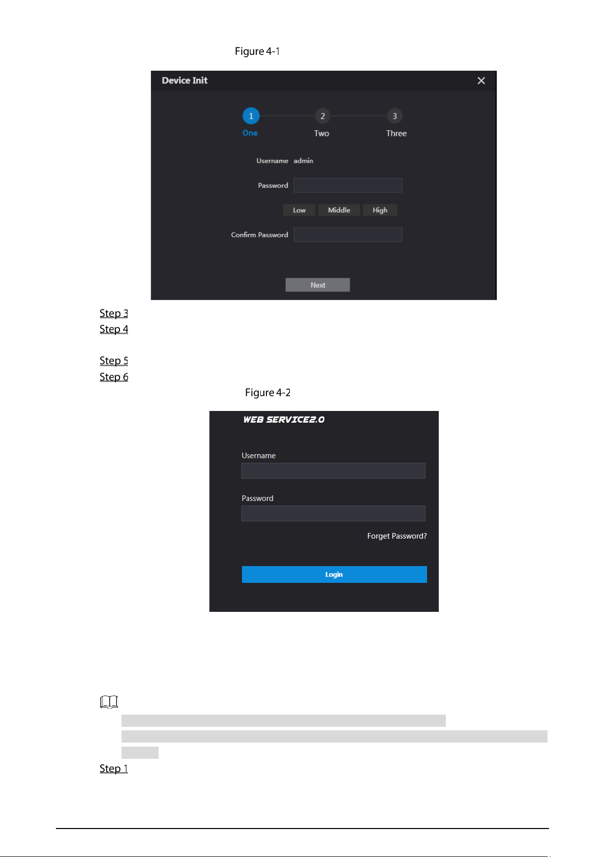
4.3.1 Initialization
The default IP address of VTO is 192.168.1.108, and make sure that the PC is in the same network
segment as the VTO.
Connect the VTO to power source, and then boot it up.
Open the browser on the PC, enter the default IP address of the VTO in the address bar, and
then press Enter on the keyboard.
11
Device initialization
Enter and confirm the password, and then click Next.
Select the email check box, and then enter your email address. This email address can be
used to reset the password.
Click Next.
Click OK.
Login interface
4.3.2 Configuring VTO Number
The VTO number can be used to differentiate each VTO, and it is normally configured according to
building number.
You can change the number of a VTO when it is not working as SIP server.
The VTO number can contain 5 numbers at most, and it cannot be the same as any room
number.
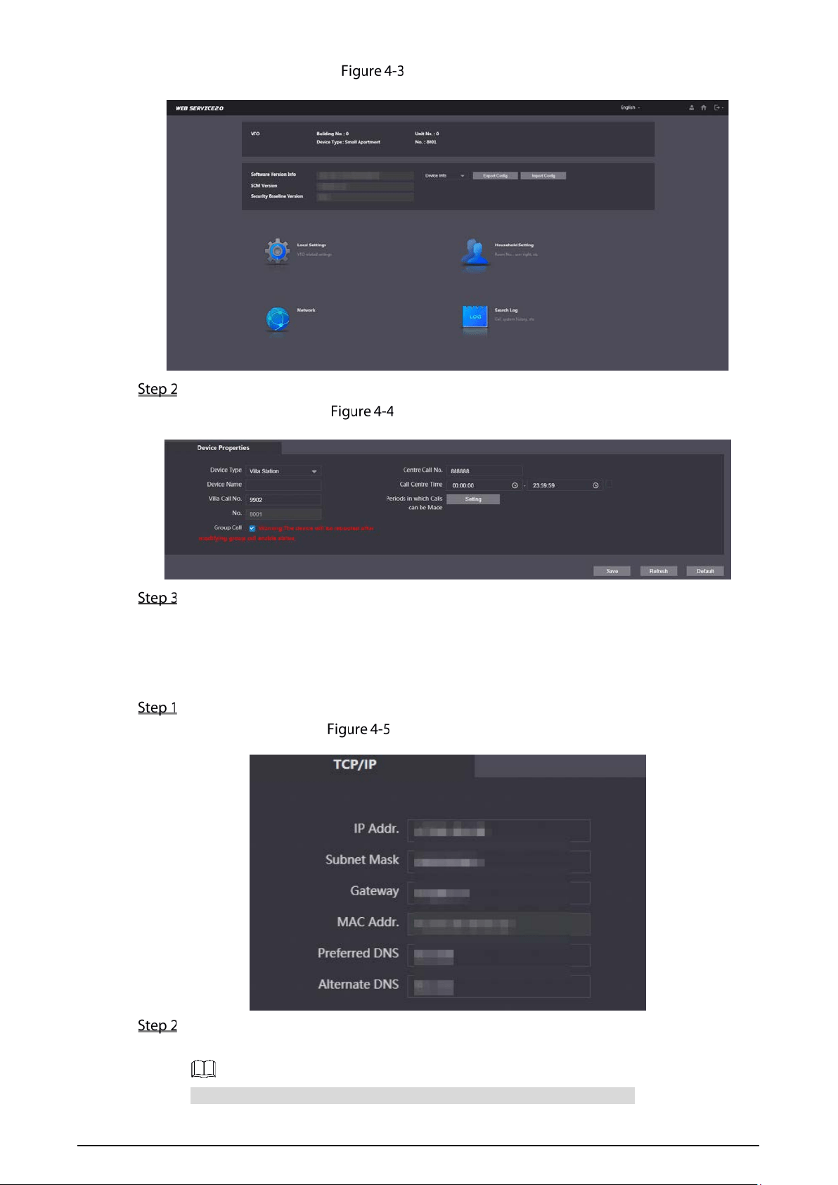
Log in to the web interface of the VTO.
12
Main interface
Select Local Setting > Basic.
Device properties
In the VTO No. input box, enter the VTO number you planned for this VTO, and then click
Confirm to save.
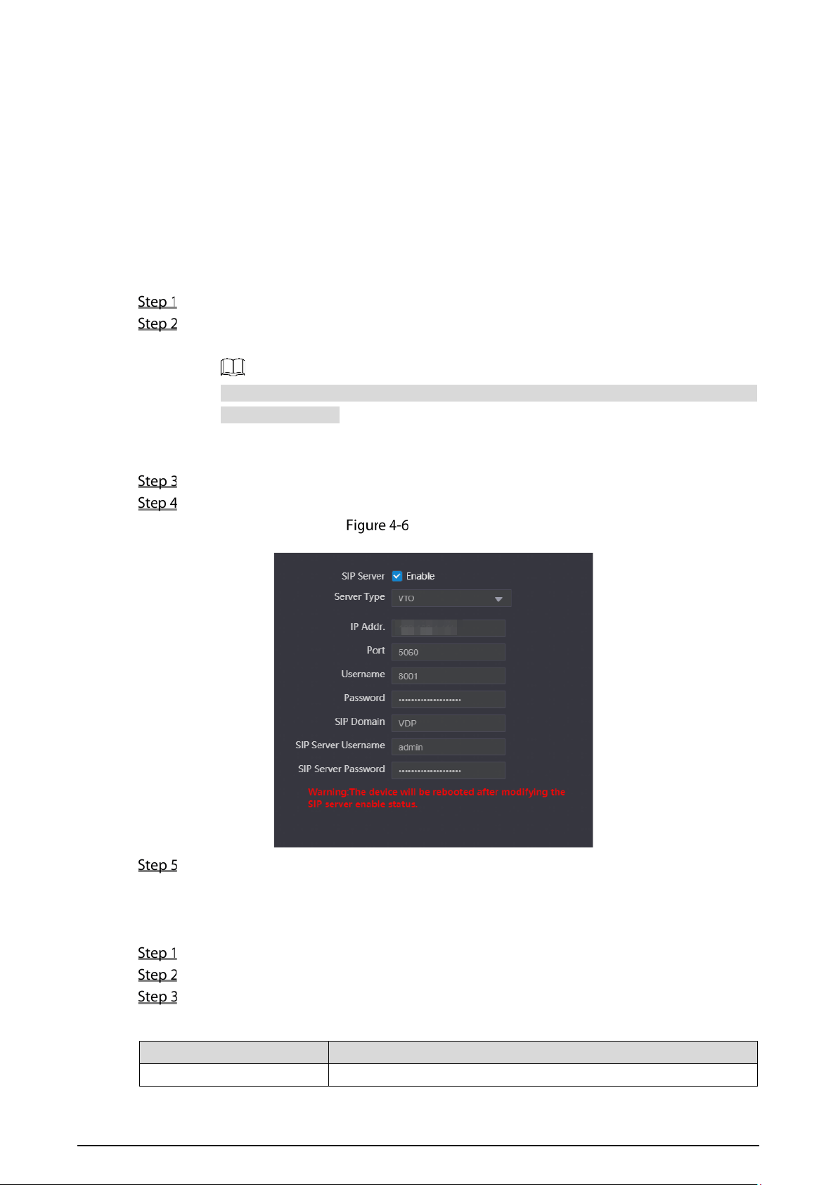
4.3.3 Configuring Network Parameters
Select Network Setting > Basic.
TCP/IP information
Enter network parameters you planned, and then click Save.
The VTO will restart.
Make IP addresses of your PC and VTO are in the same network segment.
13
4.3.4 Selecting SIP Servers
The Session Initiation Protocol (SIP) is used for signaling and controlling multimedia communication
sessions in applications of voice and video calls. A SIP server is an application provides information or
direction to a user agent.
When the door station (VTO) you are operating or another door station (VTO) works as SIP
server, select VTO from the Server Type drop-down list. It applies to a scenario where there is
only one building.
When the platform (Express/DSS) works as SIP server, select Express/DSS from the Server Type
drop-down list. It applies to a scenario where there are multiple buildings or multiple units.
Log in to the web page.
On the homepage, select Local Setting > Basic.
1) Select TCP/IP from the System Type drop-down list.
Default system type is analog system and shall be changed to TCP/IP. Otherwise, it will
fail to connect VTH.
2) Click OK to save the settings.
3) Restart the device manually, or wait for auto restart to make the settings effective.
Log in to web interface again.
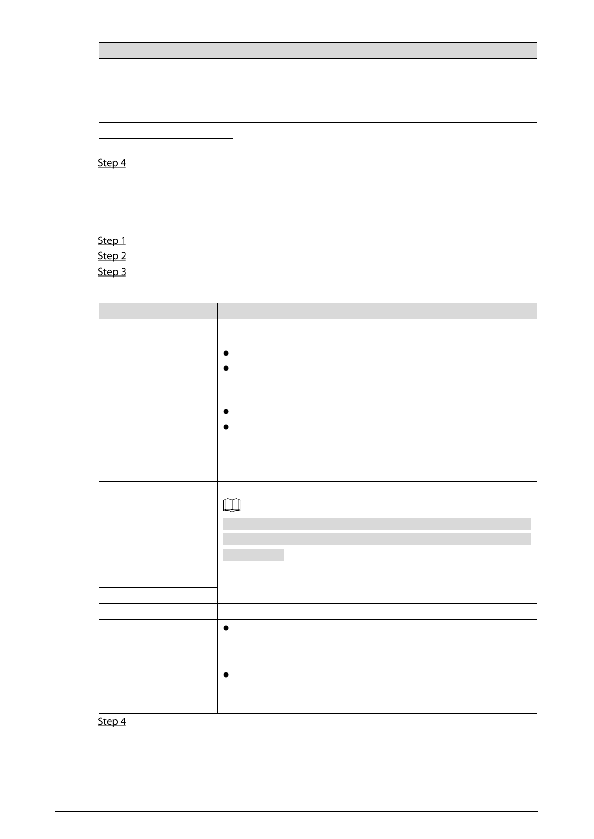
Select Network Setting > SIP Server.
SIP server (1)
Select a SIP server.
VTO as SIP server
Select Enable next to SIP Server.
Select VTO from the Server Type drop-down list
Configure parameters.
Table 4-1 SIP server configuration
Parameter Description
IP Addr. The IP address of the VTO which works as SIP server.
14
Parameter Description
Port 5060
Username
Keep the default value.
Password
SIP Domain VDP
SIP Server Username
The user name and password for the web interface of the SIP
server.
SIP Server Password
Click Save.
The VTO will restart automatically.
Platform (Express/DSS) as a SIP server
Select Network Setting > SIP Server.
Select Express/DSS from the Server Type drop-down list.
Set parameters according to Table 4-2.
Table 4-2 SIP server parameter description
Parameter Description
IP Address IP address of SIP server.
Port
It is 5060 by default when another VTO works as SIP server.
It is 5080 by default when the platform works as SIP server.
Username/Password Use default value.
SIP Domain
It shall be VDP when another VTO works as SIP server.
It can be null or keep default value when the platform works as
SIP server.
SIP Server Username/
Password
Username and password to log in to SIP server.
Alternate IP Addr.
IP address of the alternate server.
If alternate server is enabled and Express or DSS works as SIP server,
when Express or DSS cannot work normally, the VTO will be used as
the SIP server.
Alternate Username
Username and password for logging in to the alternate server.
Alternate Password
Alternate VTS IP Addr. IP address of the alternate VTS.
Alternate Server
Select the Enable checkbox after Alternate Sever, and then the
door station (VTO) you are visiting will work as the alternate SIP
server.
If you entered alternate IP address, username, password, and VTS
IP address, and then the door station (VTO) whose IP address you
entered will work as alternate SIP server.
Click OK to save the configuration.
The VTO will restart automatically.
15
When the platform works as SIP server, if it is necessary to set Building No. and Building Unit
No., enable Support Building and Support Unit first.
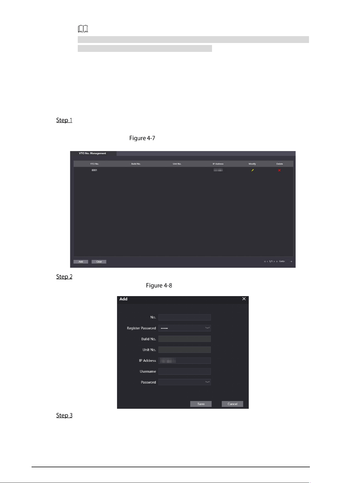
4.3.5 Adding VTO Devices
You need to add VTO to the SIP server, and all intercoms connected to the same SIP server can make
video calls among each other. This section applies to the condition in which a VTO works as SIP server,
and if you are using other servers as SIP server, see the corresponding manual for the detailed
configuration.
Log in to the web interface of the SIP server, and then select Household Setting > VTO No.
Management.
VTO No. management
Click Add.
Add VTO
Configure the parameters, and be sure to add the SIP server itself too.
16
Table 4-3 Add VTO configuration
Parameter Description
Rec No.
The VTO number you configured for the target VTO. See the details in
"4.3.2 Configuring VTO Number."
Register Password Keep default value.
Build No.
Available only when other servers work as SIP server.
Unit No.
IP Address IP address of the target VTO.
Username
The user name and password for the web interface of the target VTO.
Password
Click Save.
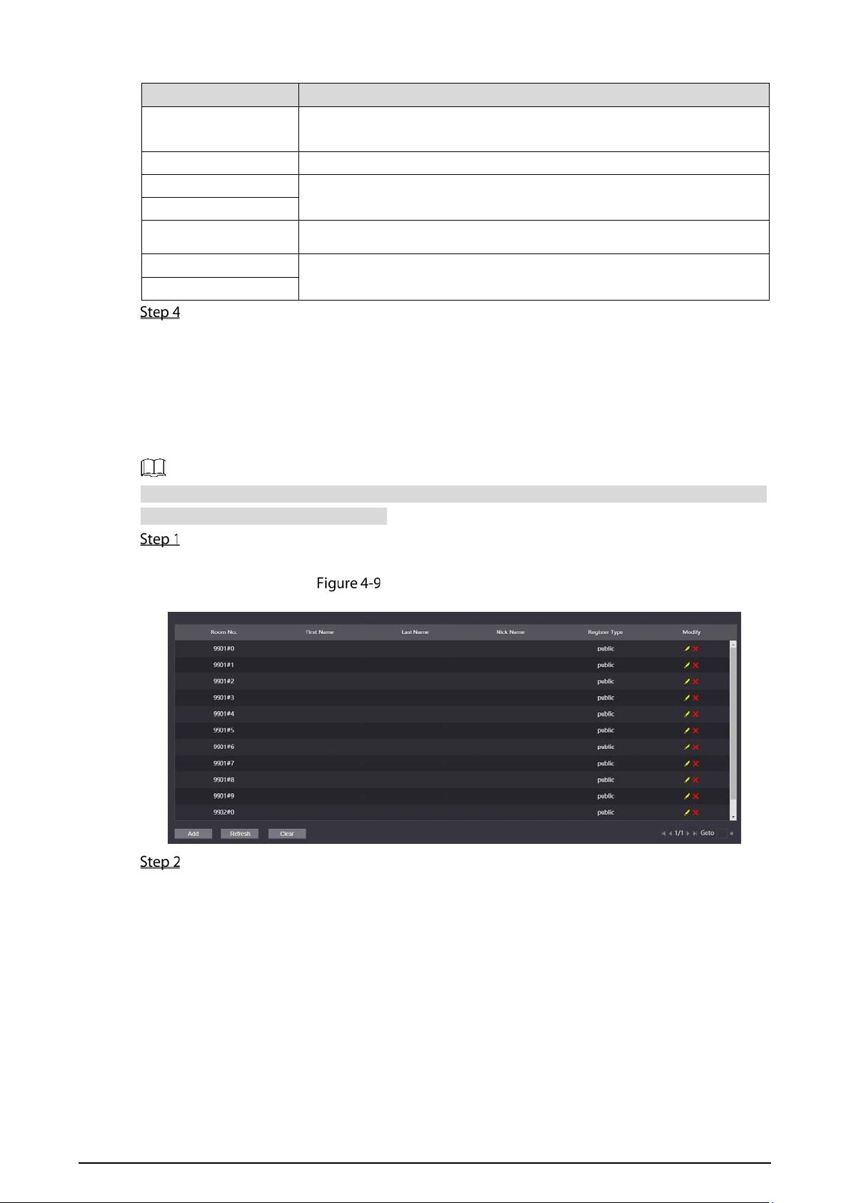
4.3.6 Adding Room Number
You can add the planned room number to the SIP server, and then configure the room number on
VTH devices to connect them to the network. VTO works as SIP server will be taken as an example,
and if you use other servers as SIP server, see the corresponding manual for the details.
The room number contains 6 digits of numbers or letters or their combination at most, and it cannot
be the same as any other VTO numbers.
Log in to the web interface of the SIP server, and then select Household Setting > Room
No. Management.
Room No. management
You can add single room number or do it in batches.
Add single room number
1) Click Add. See Figure 4-9.
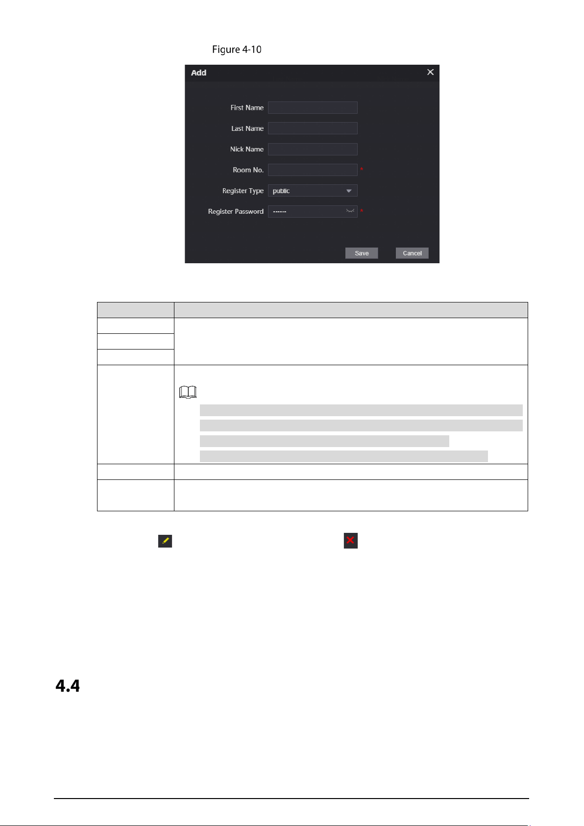
17
Add single room number
2) Configure room information.
Table 4-4 Room information
Parameter Description
First Name
Enter the information you need to differentiate each room.
Last Name
Nick Name
Room No.
The room number you planned.
If you use multiple VTH devices, the
room number of the master VTH
should be "room number#0", and the room number of the extension VTH
should be "room number#1", "room number#2", and so on.
You can have 10 extension VTH devices at most for one master VTH.
Register Type Select public, and local is reserved for future use.
Register
Password
Keep the default value.
3) Click Save.
Click to modify room information, and click to delete a room.
Add room number in batches
1) Enter the total number of floors, total number of rooms on one floor, 1st room No. of
the 1st floor, and 1st room No. of the 2nd floor as needed.
2) Click Add at the bottom left of the interface.
All the added room numbers are displayed. Click Refresh to view the latest status, and
click Clear to delete all the room numbers.
Configuring Indoor Monitor
When the indoor monitor is used for the first time, you need to select a language that you prefer,
initialize the indoor monitor to get a password to enter project setting interface and an email to reset
18
password. In addition, you need to configure parameters for all door stations (VTO) and indoor
monitors that are found on the indoor monitor you are operating.
4.4.1 Initialization
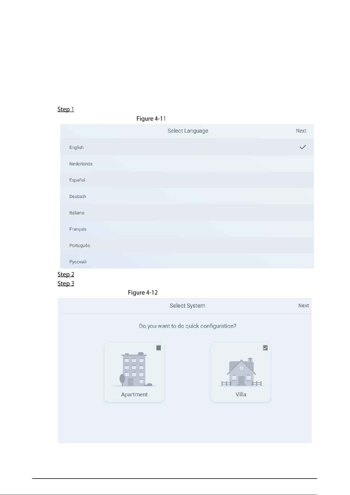
4.4.1.1 Quick Configuration for VTH (For Villa)
Power on the device.
Select a language
Select a language that you prefer.
Tap OK.
Select apartment or villa
19
Apartment: Select Apartment when the door stations and indoor monitors are
installed in apartments. Quick configuration is not available when you select
apartment.
Villa: Select Villa when the door stations and indoor monitors are installed in villas.
Quick configuration is available when you select villa.
Select Villa.
Tap OK.
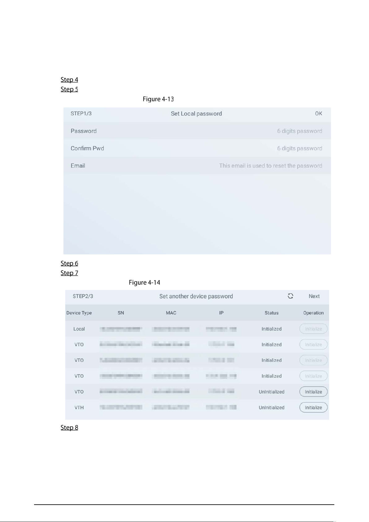
Set local password
Enter password, confirm password, and email for the VTH you are to initialize.
Tap OK.
Set another device password
Tap Refresh, and then tap Next.
20
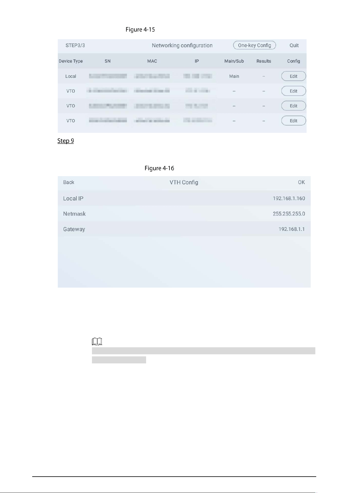
Networking configuration
Tap Edit behind each device to do configurations.
Configure indoor monitor (VTH).
1) Select an indoor monitor (VTH).
VTH config
2) Enter local IP, Network, and gateway.
3) Tap OK.
The indoor monitor (VTH) configuration is completed.
Configure Main VTO and Sub VTO. There must be only one main VTO and one or more
sub VTOs.
If there are no sub door stations (VTO), then you do not need to do sub door station
(VTO) configurations.
1) Select a door station (VTO).

21
VTO config (1)
VTO config (2)
2) Select Main or Sub.
Enter local IP, Network, gateway; select video standard, date format, time format; set
date and time.
3) Tap OK.
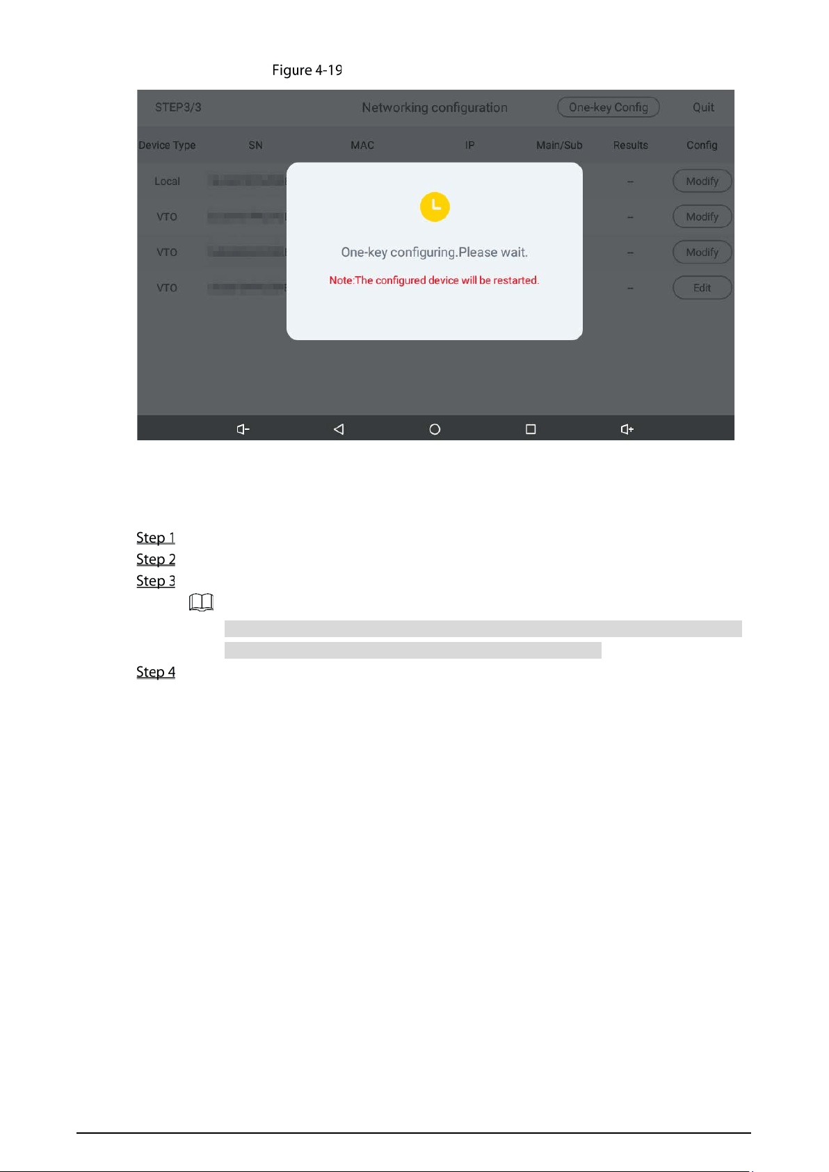
4) Tap One-key Config.
The VTO configuration will be completed in a few seconds.
22
Making the configuration effective
4.4.1.2 Normal Configuration for VTH (For Apartment)
Tap Apartment on Figure 4-12.
Connect the indoor monitor to power source.
Enter the password, confirm password, and email.
Password: The password is used when administrators need to go to the project mode.
Email: The email is used when you need to reset the password.
Tap OK.
23
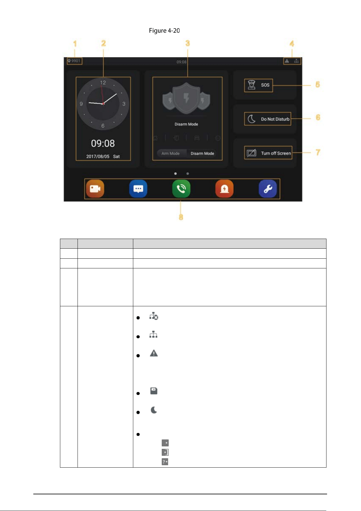
Main menu
Table 4-5 Description of main menu
No. Name Description
1 Room number Number of the room where the indoor monitor Is installed.
2 Date and time Current time and date are displayed here.
3 Arm and disarm
Shortcut icons to arm or disarm are displayed here. The four icons
represent at home mode, away from home mode, sleep mode, and
customizable mode. Select Arm Mode or Disarm Mode first, and then
tap the icons to arm or disarm.
4 Status bar
: The wired network is not connected.
: The wired network is connected.
: The indoor monitor failed to be connected to the SIP server. If
this icon does not appear, then the indoor monitor is connected
to the SIP server.
: The SD card is inserted and recognized.
: The indoor monitor is in the Do not disturb mode. It is
disabled by default.
Door Status
: Door closed.
: Door open.
: Unknown.
24
No. Name Description
5 SOS Tap the SOS icon, the indoor monitor will call the management center.
6 Do not disturb
Tap the icon, and then you can set do not disturb period.
You need to
enable DND Period
first, and then you can do do-not-disturb settings.
For details, see DND after tapping and entering the password
(123456 by default, and this password can be changed in 4.4.4.4
General).
It is recommended that the passwor be changed during the first use.
7 Turn off screen Tap the icon, and then the screen will be turned off.
8 Function buttons
: Tap the icon, and then you can watch videos from door
stations and IP cameras.
: Tap the icon
, and then text messages and videos left by
visitors, or public notices released by the management center will
be displayed.
: Tap the icon, and then you can make calls to other indoor
monitors and the management center; and you can also view call
logs and your contacts on this interface.
: Tap the icon, and then you can view alarm logs, do alarm
settings for 6 areas as needed.
: Tap the icon, enter the password (123456 by default, and this
password can be changed in 4.4.4.4 General), and then you can
select ringtones for different door stations, Do Not Disturb period,
call forward mode (there are three options: Always, Busy, and No
Answer), and other settings.
Sound Recorder: You can record your voice messages to the SD
card or to the indoor monitor.
Calculator: You can do calculations through the calculator.
Files: You can view files like images, videos, audio, and recently
produced files.
Calendar: You can view date through the indoor monitor, and
create notes, schedules, and plans.
Gallery: You can view images captured by door stations (VTO) or
IP cameras.
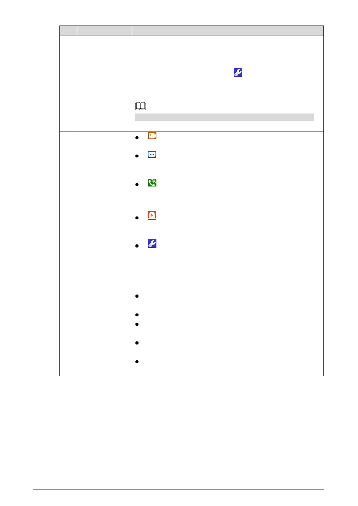
4.4.2 Network Settings
Connect the indoor monitor to the network, and then the indoor monitor can communicate with
other devices.
25
Wired Network
Make sure that IP address of the indoor monitor and IP address of door stations are in the same
network segment; otherwise the indoor monitor cannot acquire door station information.
Tap the Settings icon.
Enter the password (123456 by default, and this password can be changed in 4.4.4.4
General).
Network settings
Configure parameters.
Table 4-6 Parameter description
Parameter Description
Network &
Internet
You can choose to enable Wi-Fi or not by tapping .
Tap , and then available Wi-Fi networks will be displayed.
You can select Ethernet IP mode. There are two options: Static and D H C P.
Apps &
notifications
You can view the recently opened apps, apps opened by default, app permissions
(apps using location, microphone, and camera), app notifications, and special app
access.
Display You can adjust display brightness, display sleep duration, font size, and display size.
Sound
You can adjust media volume and notification volume. You can also select to use
default notification sound and default alarm sound.
Storage
Spaces used and spaces left can be viewed. You can delete unwanted files as
needed.
System
Languages &
Input
Languages: You can select languages as needed.
Keyboard & Inputs: There are two options: Virtual keyboard
and physical keyboard.
Input assistance: You can use spell checker, autofill service
(not available at pres
ent), personal dictionary, and
text-to-speech output as needed. Pointer speed can also be
adjusted.
Backup You can use backup storage as needed.
26
Parameter Description
Reset
options
You can reset Wi-Fi, mobile, and Bluetooth, and app preferences.
You can also erase all data, which means restoring
the indoor
monitor to factory settings.
About tablet
You can see details (battery status, network status, legal
information, model, android version, Android security patch level,
baseband version, Kernel version, build number, and more) about
the indoor monitor.
Tap Network & Internet.
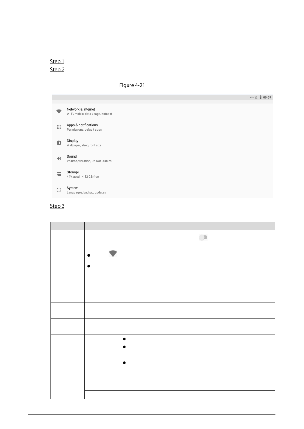
Tap Ethernet.
Network setting
Tap Ethernet Ip mode.
Select static: Enter IP address, gateway, netmask, and then tap CONNECT.
Select dhcp: Tap dhcp, the IP information will be automatically acquired.
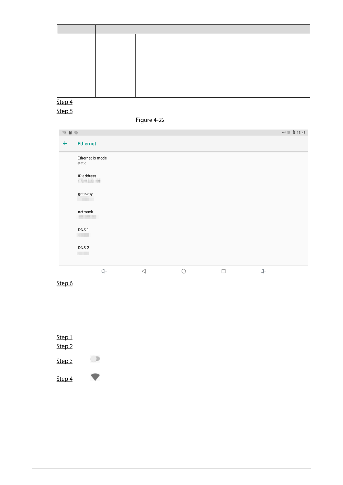
Wireless Network
Tap the Settings icon.
Tap Network & Internet.
Tap , the Wi-Fi is enabled.
Tap , the available wireless networks are displayed.
27
Wi-Fi
Select a wireless network.
Enter the password.
Tap CONNECT.
The network is connected.
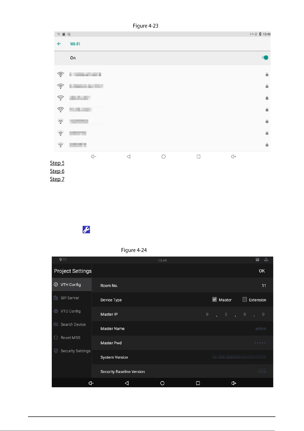
4.4.3 Project Settings
Tap and hold , enter the password (the password set during initialization), and then the Project
Settings interface will be displayed.
Project settings
28
4.4.3.1 VTH Config
Room No.: Number of the room where the indoor monitor is installed.
Device Type: There are two options: Master and Extension.
Master: If the indoor monitor that you are operating works as the master station, you need
to select Master.
Extension: If the indoor monitor works as an extension, you need to select Extension.
Master IP: When the indoor monitor works as an extension, you need to enter IP address of the
master station.
Master Name: Keep the default value.
Master Pwd: The password you set during initialization (6 characters).
System Version: You can view system version of the indoor monitor.
Security Baseline Version: You can view security baseline version of the indoor monitor.
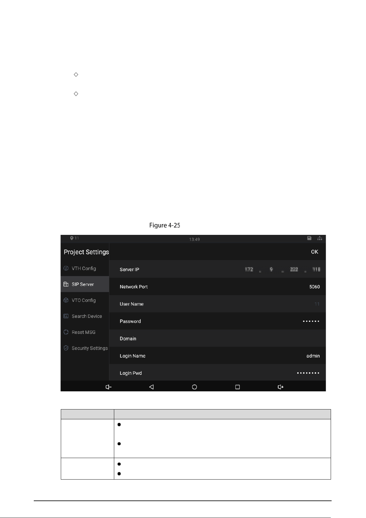
4.4.3.2 SIP Server
You need to enter SIP server information, and then video door phones in the same system can
communicate with each other.
Tap SIP Server.
SIP server (1)
Table 4-7 SIP server description
Parameter Description
Server IP
When the platform works as SIP server, server IP is IP address of the
management platform.
When a door station works as SIP server, server IP is IP address of the door
station.
Network Port
When the platform works as SIP server, network port is 5080.
When VTO works as SIP server, network port is 5060.
29
Parameter Description
User Name
Keep default value.
Password
Domain
Registration domain of SIP server, which can be null.
When VTO works as SIP server, registration domain of SIP server shall be VDP.
Login Name
Username and password to log in to web of the SIP server.
Login Pwd
Status Enable the SIP server status, and then the SIP server can start to work.
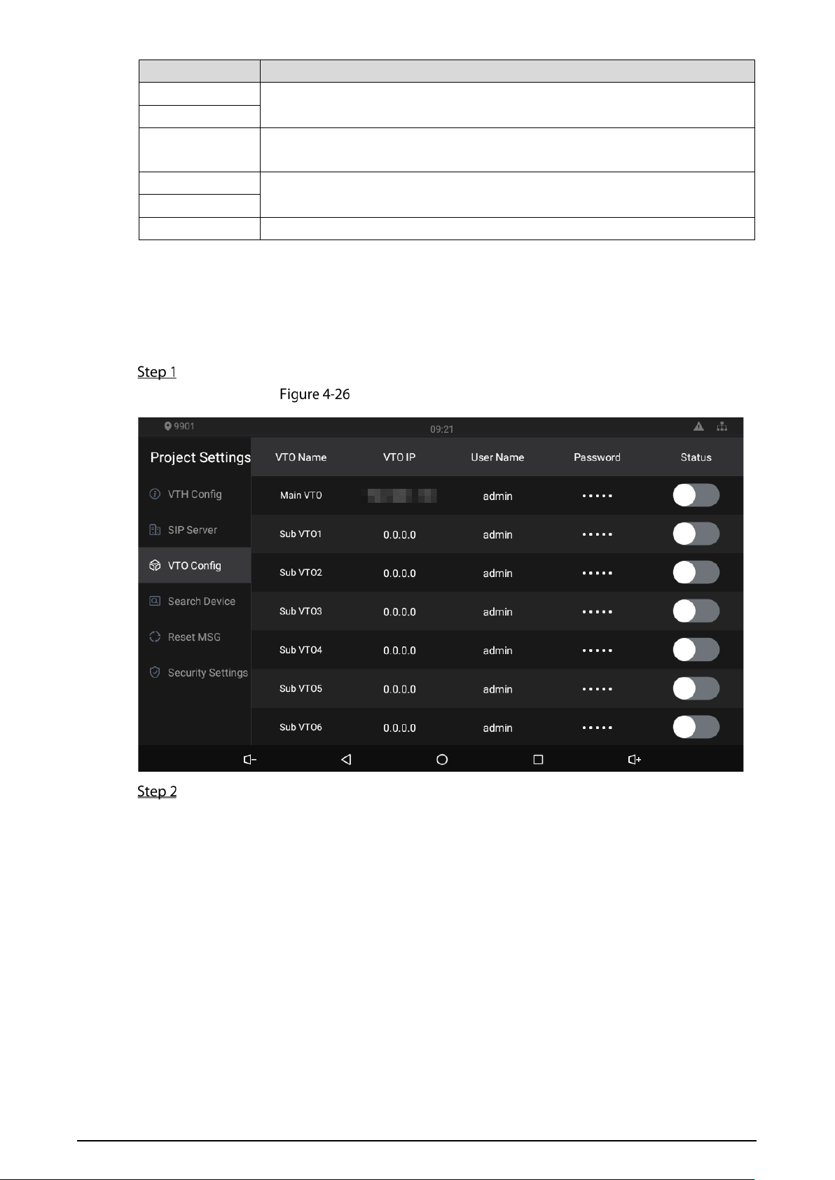
4.4.3.3 VTO Config
You need to add door stations to the indoor monitor, and then calls can be made among door
stations and indoor monitors.
Tap VTO Config,
Door station (VTO) configuration
Tap a door station (VTO).
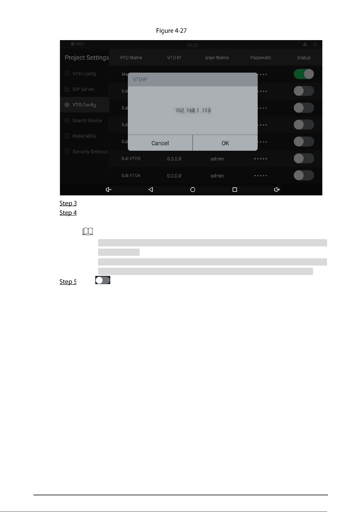
30
VTO IP
Tap the default IP, and then the on-screen keyboard appears.
Enter the door station (VTO) IP, user name, and password (used to log in to the door station
web interface).
You can add 20 door stations (one main door station and 19 sub door stations) to the
indoor monitor.
Make sure that user name and password that you entered here are the same as the
user name and password used when logging in to the door station web interface.
Tap to enable the door station.
4.4.3.4 Searching Device
Tap the Search Device icon, and then the system starts to search devices automatically. You can add
the device found to the indoor monitor.
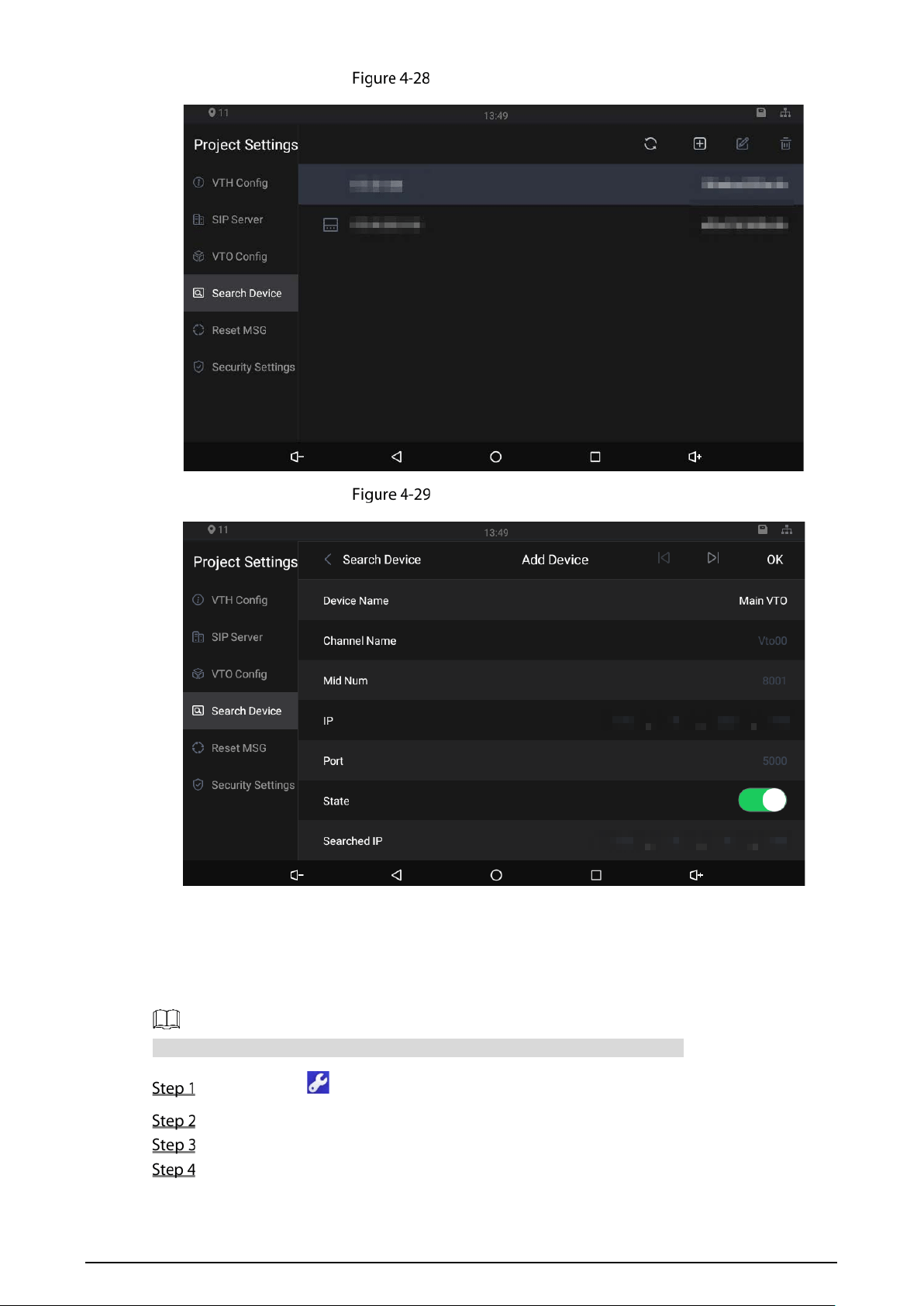
31
Searching device (1)
Searching device (2)
4.4.3.5 Resetting Password
You can change the email address that you use to reset your password.
You need to enable the Resst Password first if you want to reset the password.
Tap and hold .
Tap Forgot password?.
Tap OK.
Scan the QR code with any app with scanning function.
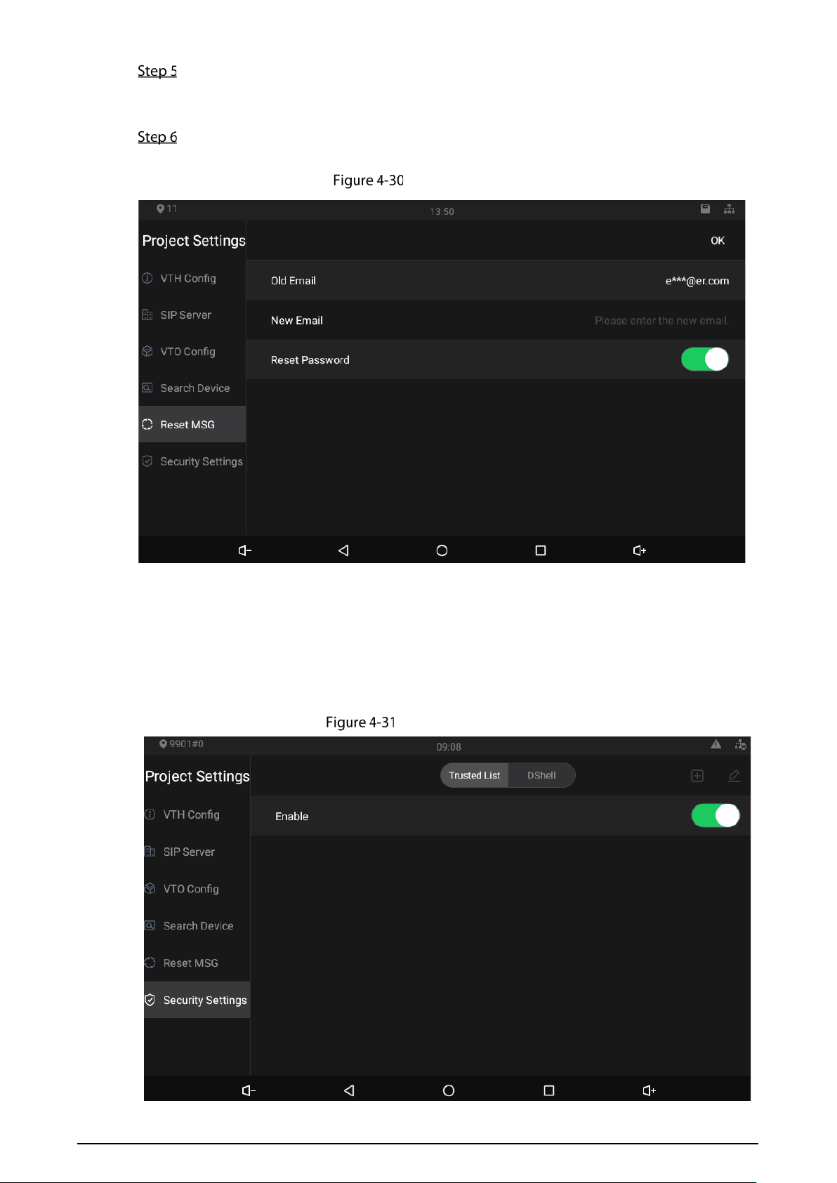
32
Send the string to the email address displayed on your device interface with the email
address you set on the Reset MSG interface.
A safe number will be sent to your email address.
Tap Next and then enter the new password, confirm password, and safe number.
The password is reset.
Reset password
4.4.3.6 Security Settings
You need to enable the trusted list, and then trusted devices can communicate with the indoor
monitor. You can also use Dshell to get the ability to develop custom analysis modules which help
you understand events of cyber intrusion.
Enable trusted list
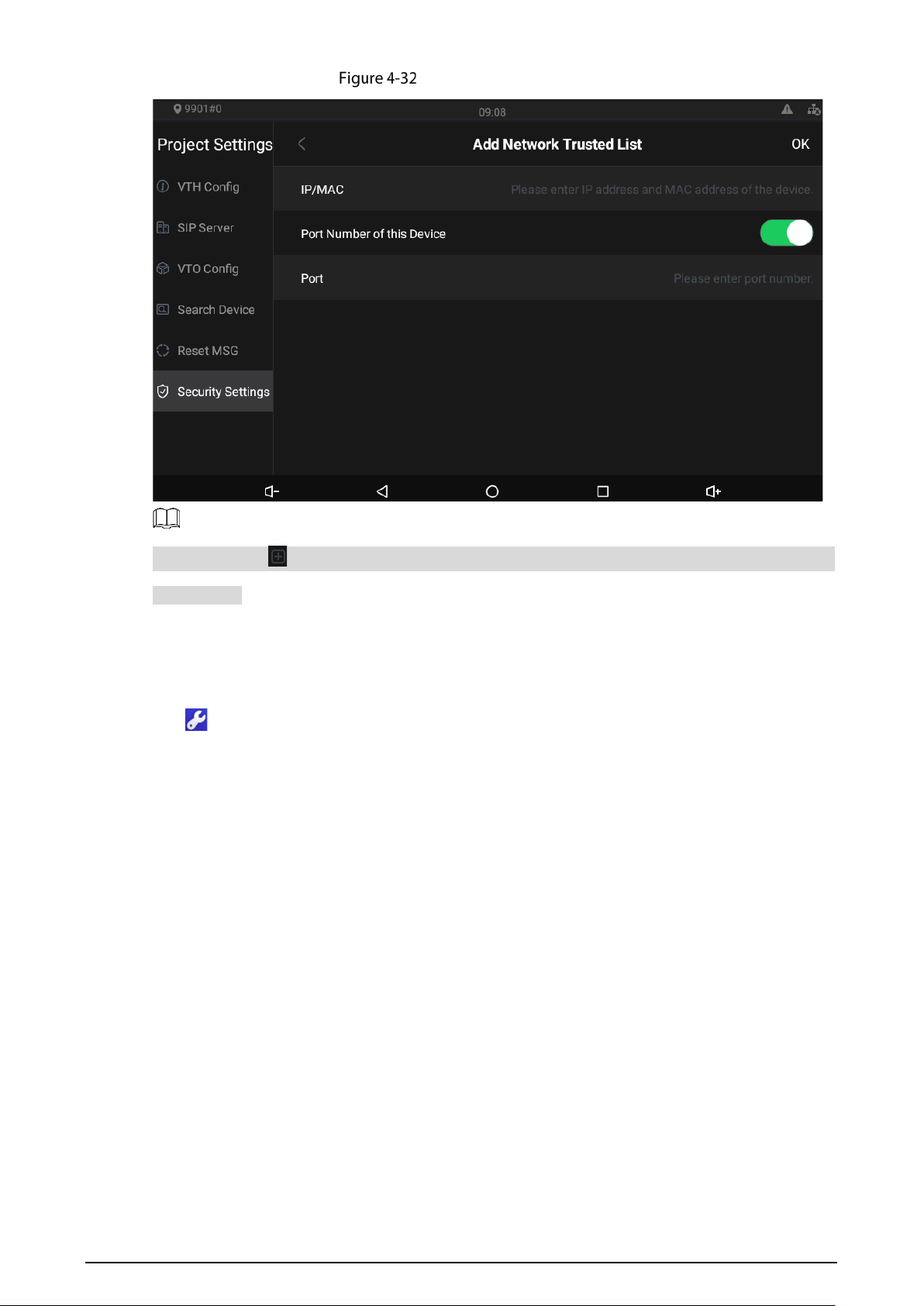
33
Add network trusted list
You need to tap on the enable trusted list interface, and then the Add Network Trusted List will
be displayed.
4.4.4 General Settings
Tap , enter the password (123456 by default, and this password can be changed in 4.4.4.4
General). You can select ringtones for different door stations, Do Not Disturb period, call forward
mode (there are three options: Always, Busy, and No Answer), and other settings.
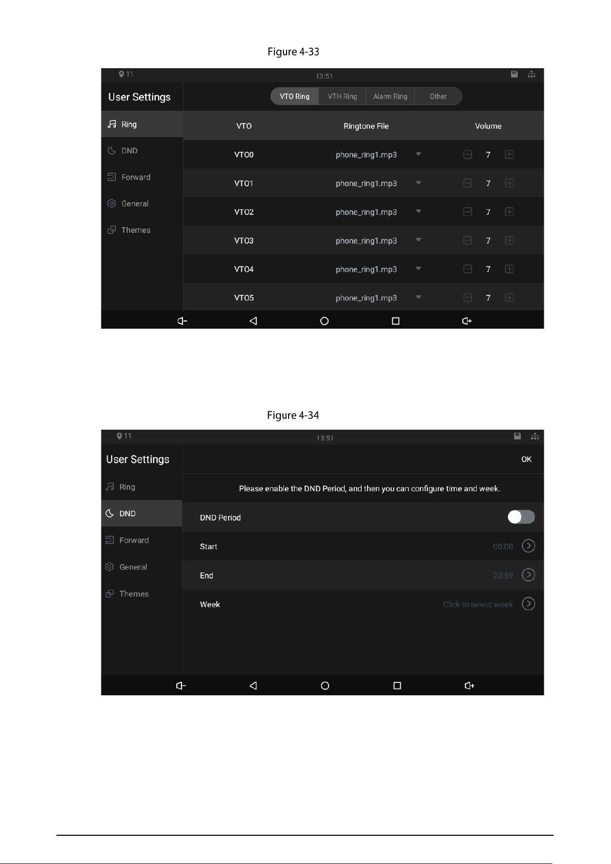
4.4.4.1 Ring
On this interface, you can select ringtones for different door stations, indoor monitors, and alarm
devices.
34
Ring
4.4.4.2 DND
Enable DND Period first, and then you can set do not disturb period for each day.
DND
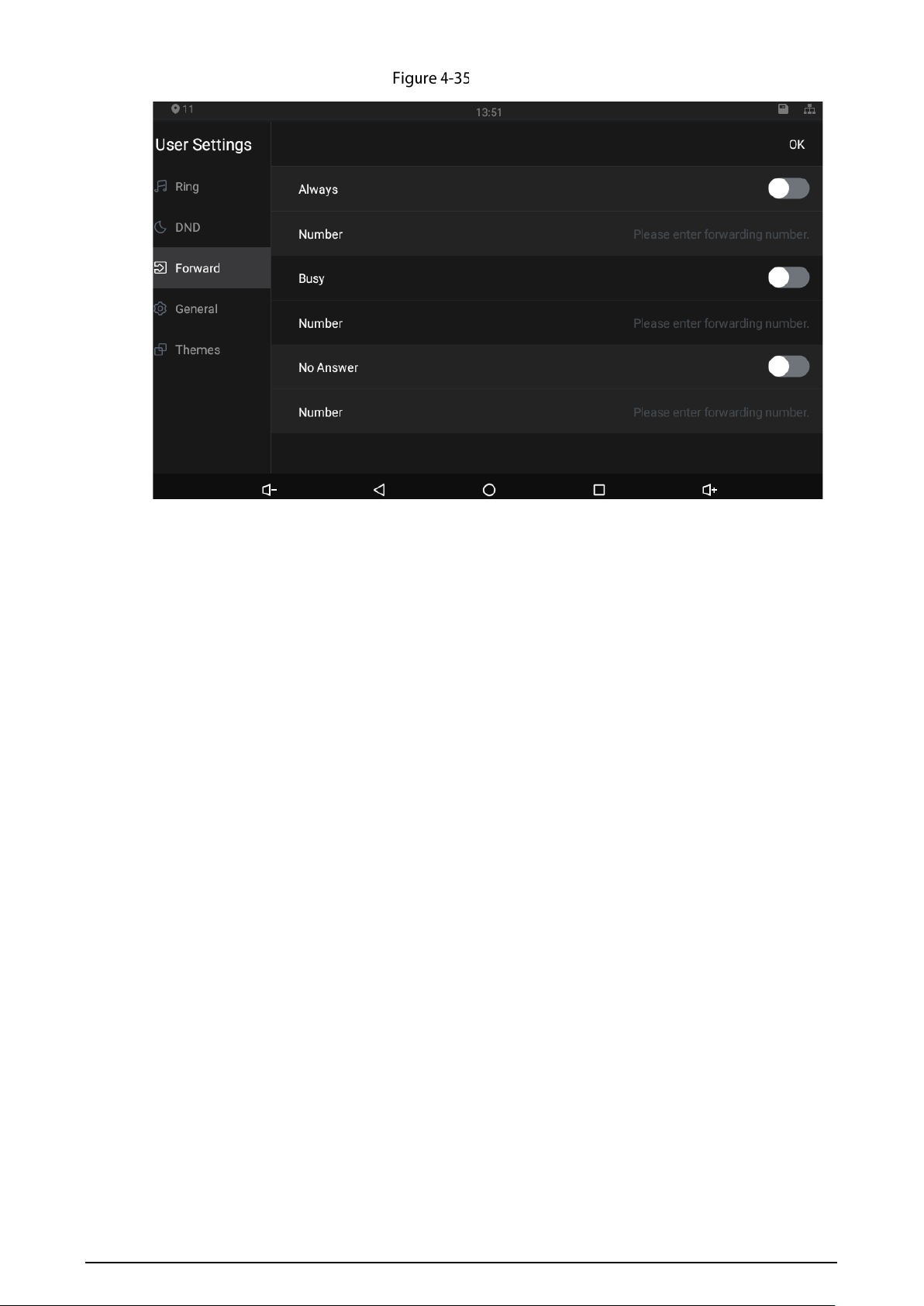
4.4.4.3 Forward
When calls come in, they will be forwarded to the numbers you have set in advance. There are three
options: Always, Busy, and No Answer.
35
Forward
Always: Whenever calls come in, they will always be forwarded.
Busy: If calls come in when you are talking to others over the indoor monitor, the calls will be
forwarded.
No Answer: When the coming calls are not answered, they will be forwarded.
If you want to forward the call to residents in other apartment, you need to enter 0101101 for
building 1 + apartment 1 + room 101.
If you want to forward the call to residents in your apartment, enter the number of the room
where the indoor monitor is installed.
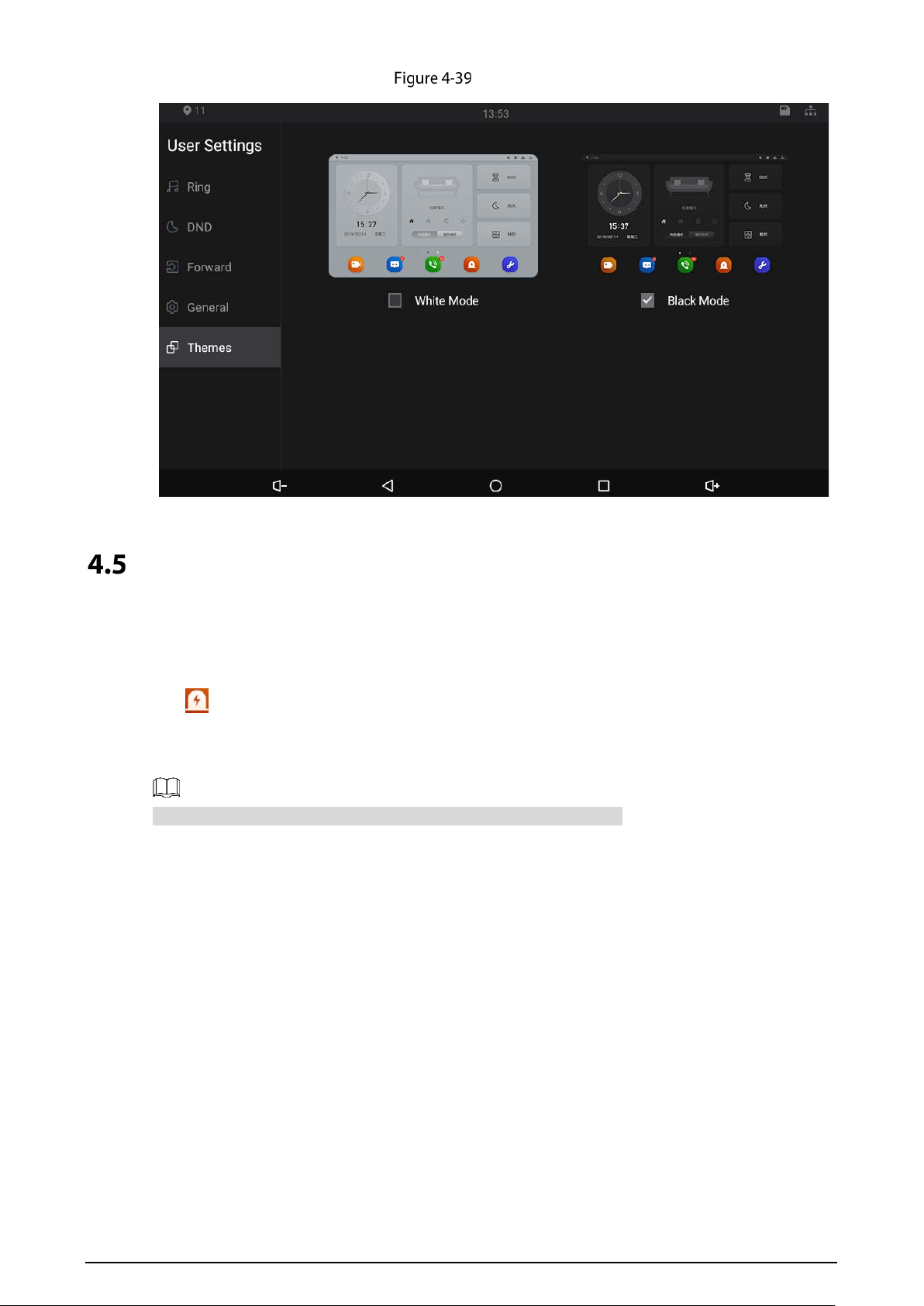
4.4.4.4 General
On the General interface, you can set new passwords for arming and disarming, registering new
users and downloading apps by scanning QR codes, and setting other parameters.
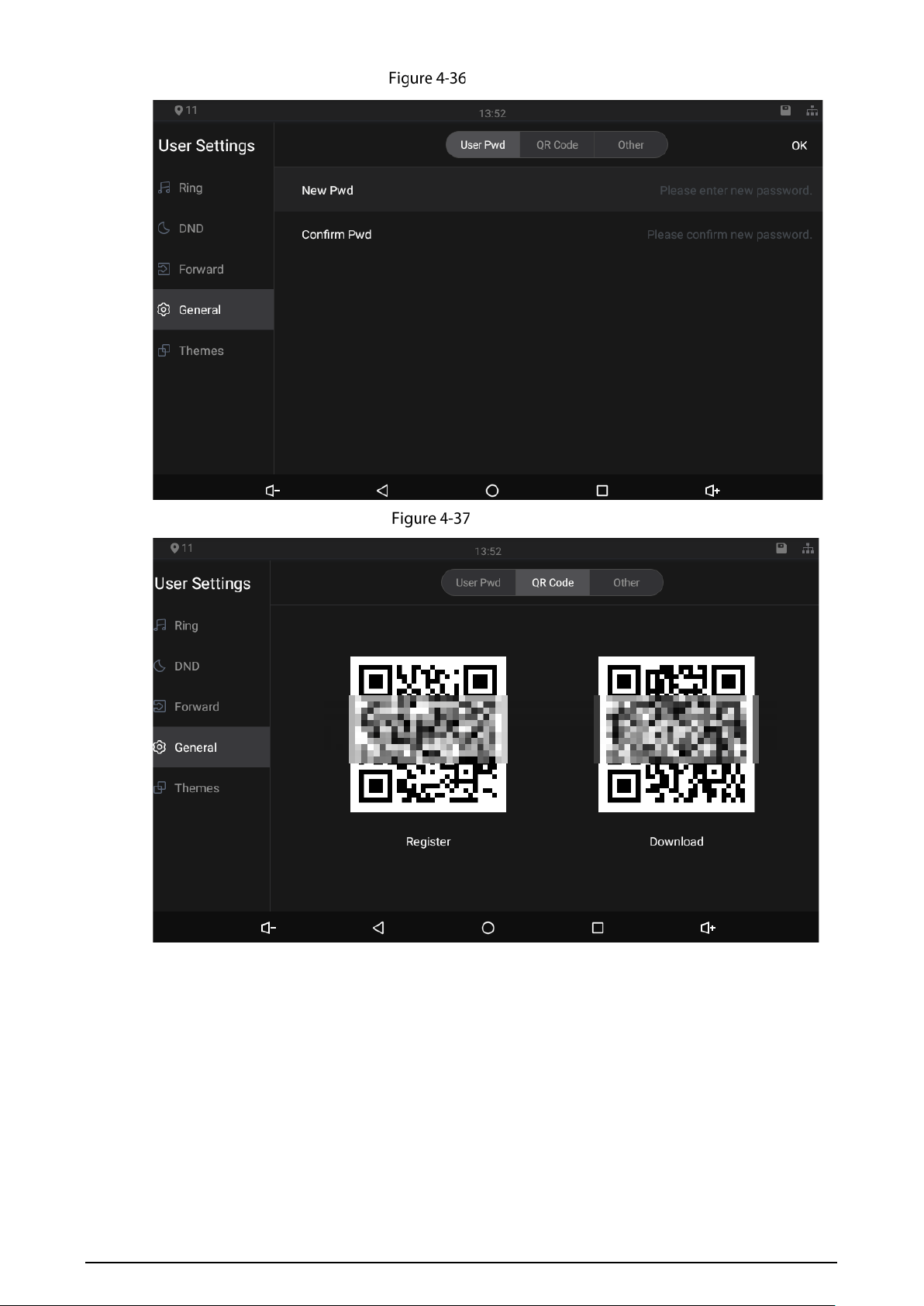
36
Password
QR code
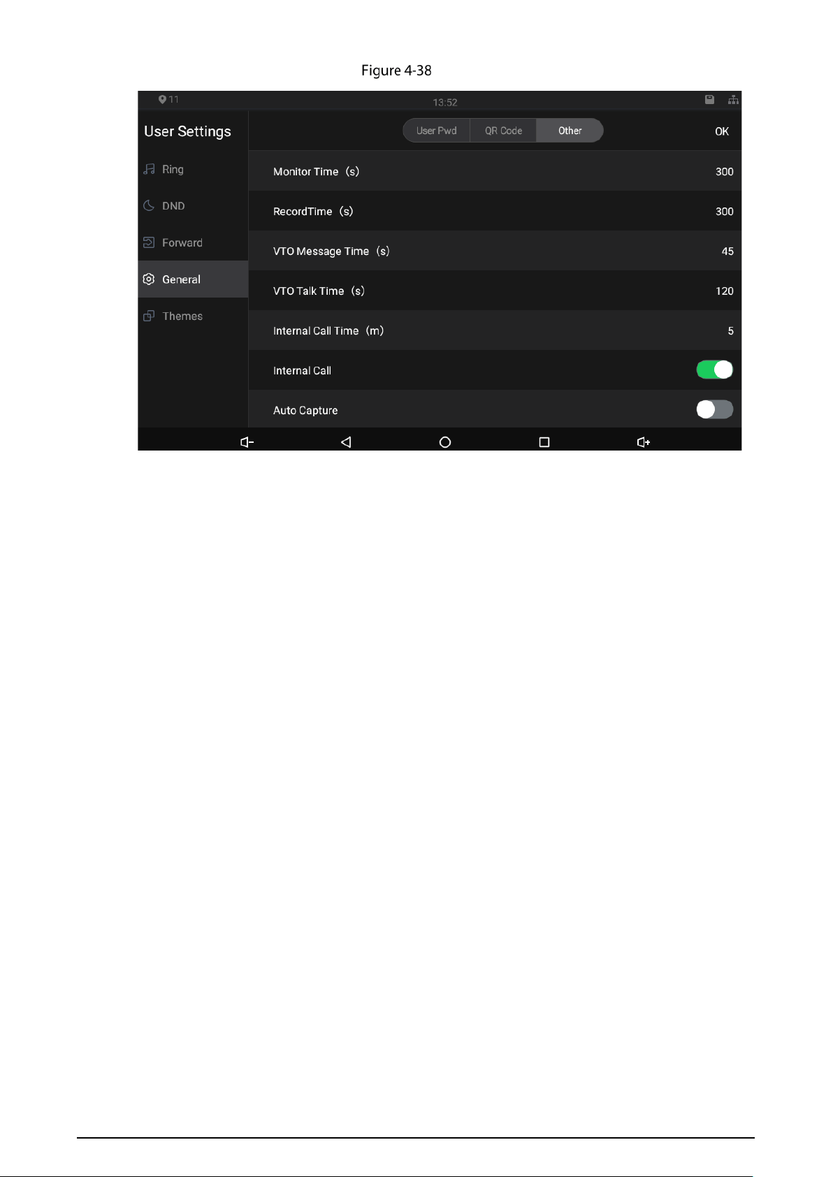
37
Other
Monitor Time (s): You can watch monitoring images from the indoor monitor for at most 300
seconds a time.
Record Time (s): You can record at most 300-second audio files a time on the indoor monitor.
VTO Message Time (s): Visitors can only leave an at most 90-second message a time on the door
station (VTO).
VTO Talk Time (s): Visitors can talk to you through the door station (VTO) for at most 300 seconds
a time.
Internal Call Time (s): You can talk to other indoor monitors for at most 60 minutes a time.
Internal Call: After the Internal Call is enabled, you can call other indoor monitors from the
indoor monitor you are operating.
Auto Capture: After the Auto Capture function is enabled, if a visitor called you but you did not
answer the call, the door station (VTO) would take three images of the visitor standing in front
of the door station. This function is available when SD card is inserted into the indoor monitor.
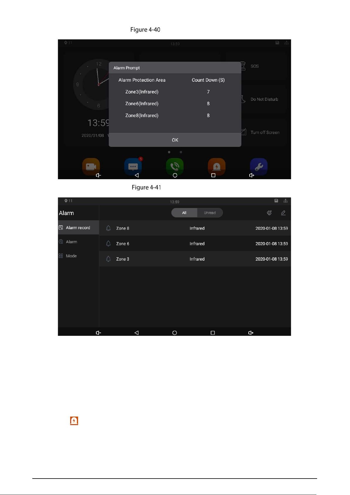
4.4.4.5 Themes
You can select a theme for your indoor monitor. There are two options: White Mode and Black
Mode.
38
Themes
Alarm
4.5.1 Alarm Record
Tap . Peripheral alarm modules can be connected to the indoor monitor. You can view alarm logs,
do alarm settings for 8 areas as needed. There are 7 types of alarms: Infrared, gas sensor, smoke
sensor, urgency button, door sensor, stolen, perimeter, and doorbell.
Select Disarm on the main menu, and then you can do alarm settings.
39
Viewing alarm prompt
Viewing alarm record
4.5.2 Alarm Settings
4.5.2.1 Wire Zone
Set alarm settings for eight areas, and then if emergencies happen, alarms will be triggered.
Tap .
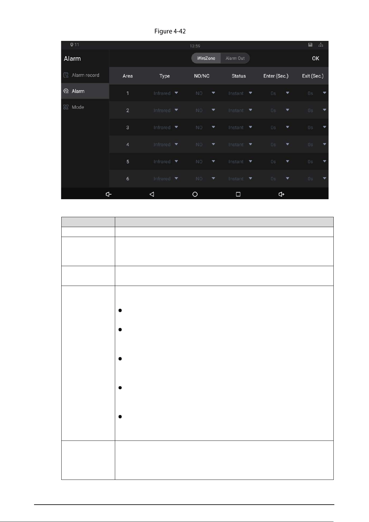
40
Wire zone
Table 4-8 SIP server description
Parameter Description
Area Area numbers. There are 8 areas in total. They cannot be modified.
Type
There are 8
types of alarms: Infrared, gas sensor, smoke sensor, urgency
button, door sensor, stolen, perimeter, and doorbell. Select alarm types
according to detector types.
NO/NC
Select NO (normally open) or NC (normally closed) according to detector
types. It shall be the same as detector type.
Status
There are 5 statuses: Instant, delay, bypass, remote, and 24-hour protection
zone.
Instant: In Arm Mode, if you selected this status for an area, once alarms
are triggered, the indoor monitor will give out voice prompt immediately.
Delay: In Arm Mode, if you selected this status for an area, once alarms
are triggered, the indoor monitor will give out voice prompt a period
later.
Bypass: If you selected the bypass status for an area, after the area has
been armed and alarms are triggered; there will be no voice prompt.
Once the area is disarmed, alarm status will be back to normal.
Remove: When you select Arm Mode and Disarm Mode for an area in "at
home mode", "away from home mode", "sleep mode", and "customizable
mode", the status of this area will not be changed.
24-hour protection zone: If you selected this status for an area, no matter
Arm on the main menu is selected or not, whenever alarms are triggered,
voice prompt will always be given out.
Enter (Sec.)
In the Arm Mode, after you have selected this status for an area, there will be
no voice prompt when you enter the area from a disarmed area within the
period you set; after that period has passed in the Arm Mode, voice prompt
will be given out.
41
Parameter Description
This function is only available when you have selected Delay status for an area.
Exit (Sec.)
In the Arm Mode, after you have selected this status for an area, there will be
no voice prompt unit you have exit the area within the period you set. After
that period has passed in the Arm Mode, voice prompt will be given out when
alarms are triggered.
This function is only available when you have selected Delay status for an
area.
If you have selected this status for more than one area, and then prompts
of the area with the longest
period will be displayed on the indoor
monitor.
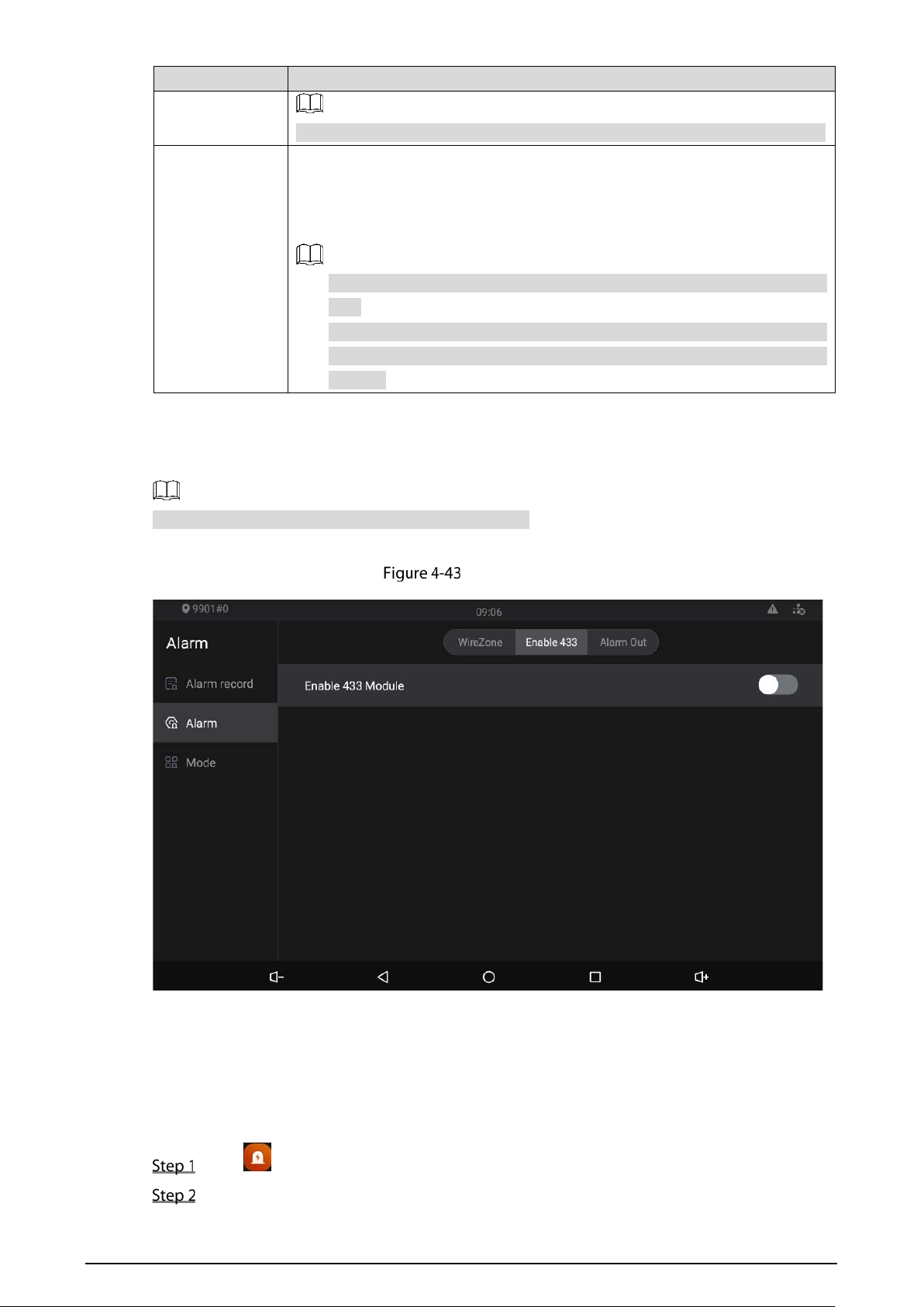
4.5.2.2 Enable 433
This function is only available for models ending with A.
Only after you have enabled 433, the Wireless Zone interface will appear.
Enable 433
4.5.2.3 Wireless Zone
On the WirelessZone interface, you can add alarm devices for alarm areas, and then if alarms are
triggered, alarm messages will be pushed to the indoor monitor.
Tap on the main menu.
Select Enable 433.
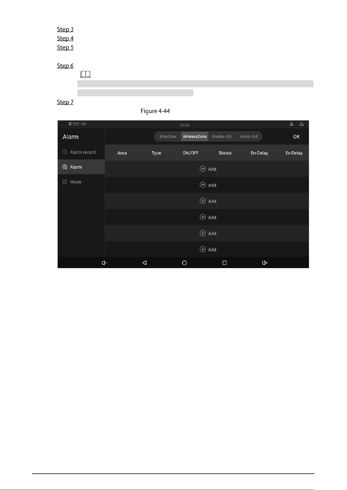
42
Enable 433.
Tap WirelessZone.
Tap Add.
The indoor monitor enters the paring mode.
Press the paring button on the alarm device.
Tap the device added, slide to the left, and then the delete button will appear. Tap deleting
button to delete the device that you selected.
Tap OK.
Wireless zone
4.5.2.4 Alarm Out
After you have enabled the alarm output function, when there are people making calls to the indoor
monitor from other devices, alarm devices will send alarms.
43
Alarm out
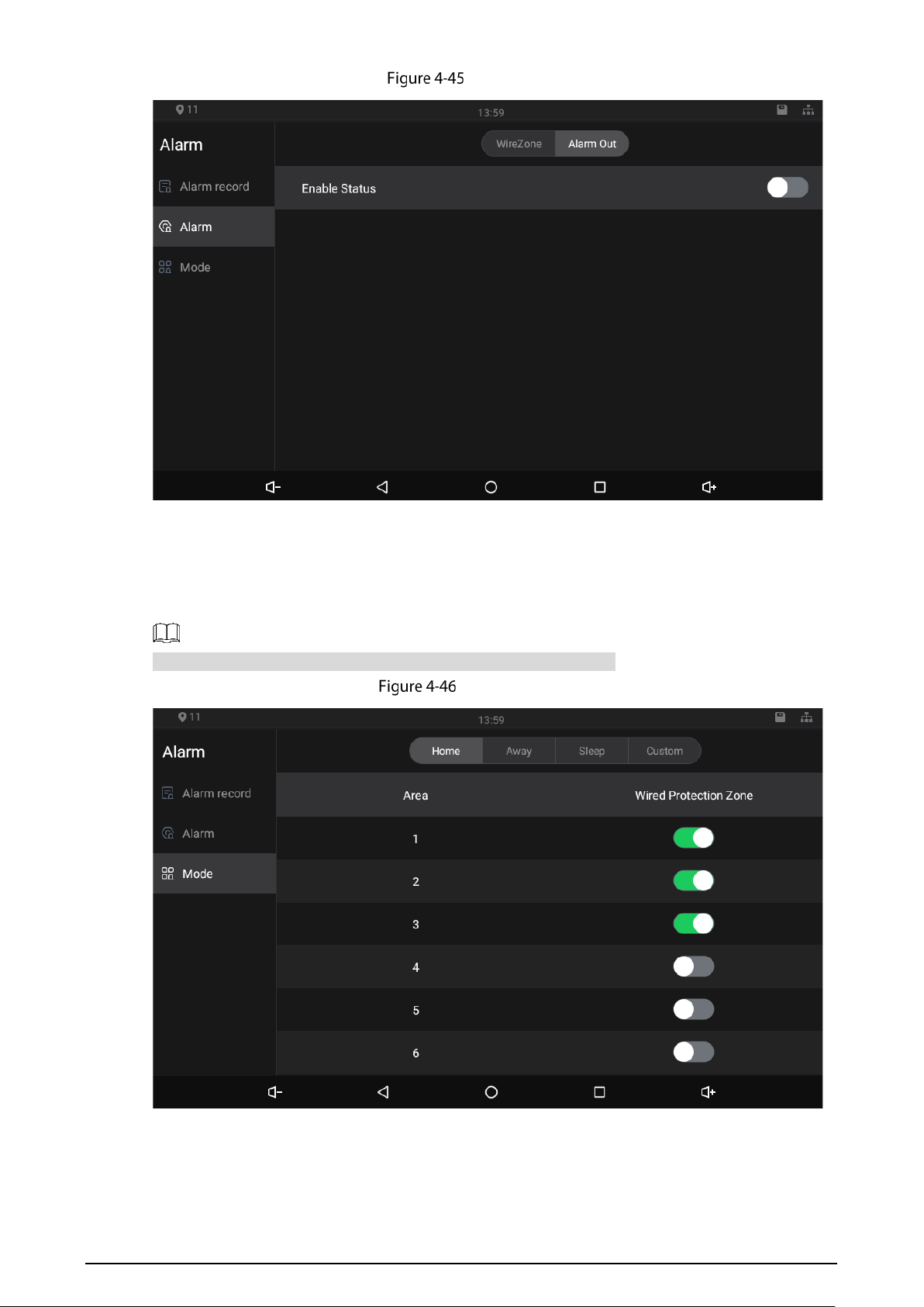
4.5.3 Alarm Mode
There are four modes: Home, away, sleep, and custom. Select modes as needed.
Only in the Disarm Mode can you enable alarm modes for the areas.
Alarm mode
44
Unlocking
You can unlock doors connected to the door stations through the indoor monitor when watching
monitoring videos, when someone is calling you from the door station, or when talking to the
people at the door station over the indoor monitor.
Arm/Disarm
After areas are armed, when alarms are triggered, alarm messages will be pushed to the indoor
monitor.
Make sure that areas you want to arm are armed; otherwise alarms will not be triggered.
Make sure that the area is in the disarmed status; otherwise you cannot arm the area. When
Disarm Mode on the interface is white, it means that the indoor monitor is in the disarm mode.
4.7.1 Arm
Tap Arm Mode on the main menu.
Arm
Select an arm mode.
There are four modes: Home, Away, Sleep, and Custom. Select as needed.
Enter the arm/disarm password, and tap OK.
You will hear beeps. It means that you have armed successfully.
45
The default arm/disarm password is 123456. If you want to change it, see "4.4.4.4
General."
If you selected Delay for the alarm status of an area, you will hear the beeps after the
delayed duration has passed.
4.7.2 Disarm
Make sure that areas you want to disarm are armed; otherwise you cannot disarm the area.
If you are forced to enter arm/disarm password to disarm, you can enter the hijacking password
(enter the arm/disarm password in reverse order), and then the management center will receive
your asking for help information.
Elevator Control
Elevator control modules can be connected to the indoor monitor. You can make the elevator come
to your floor through the indoor monitor. Once elevator control module is connected, there is an
elevator control button on the main menu of the indoor monitor.
Commissioning
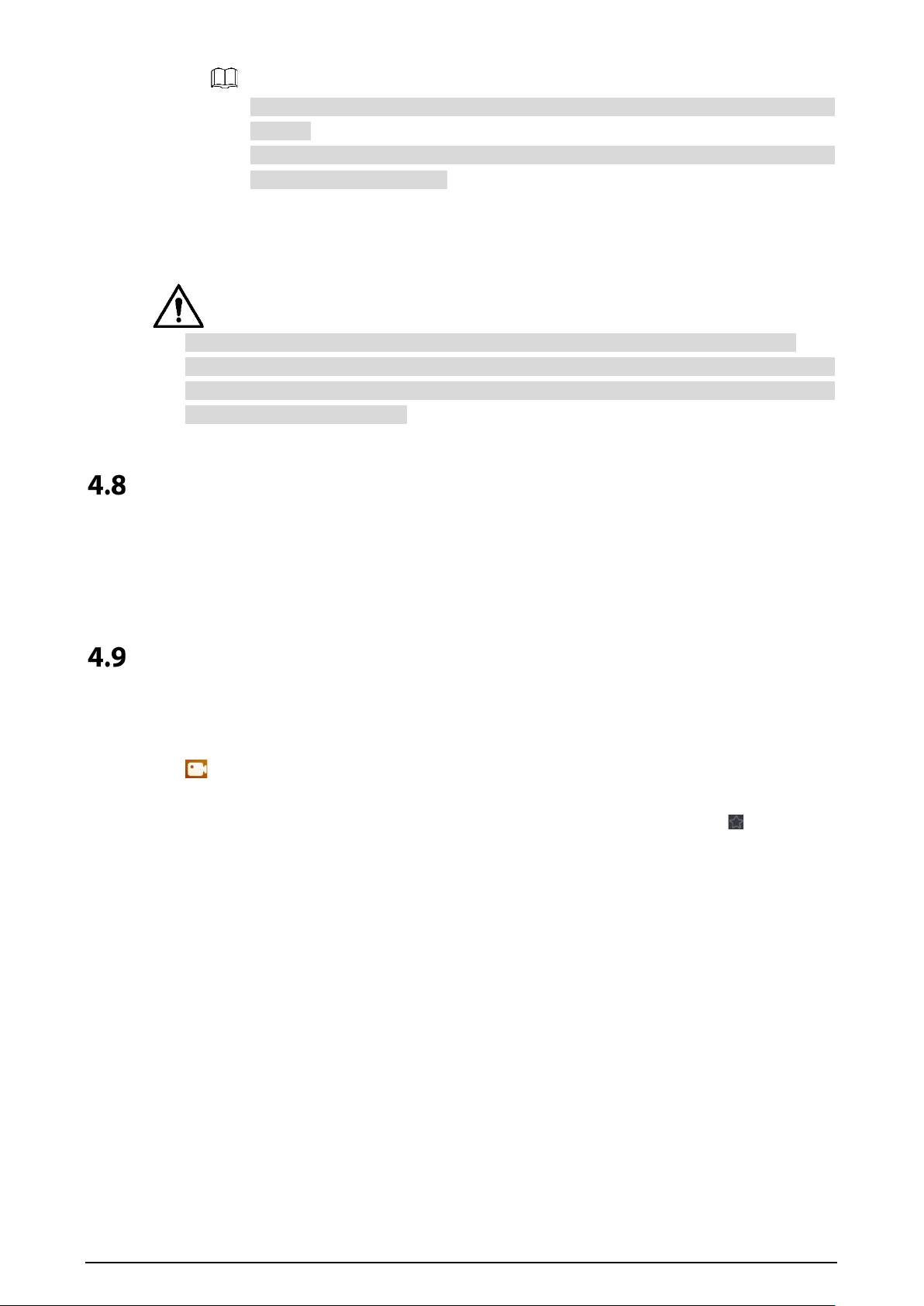
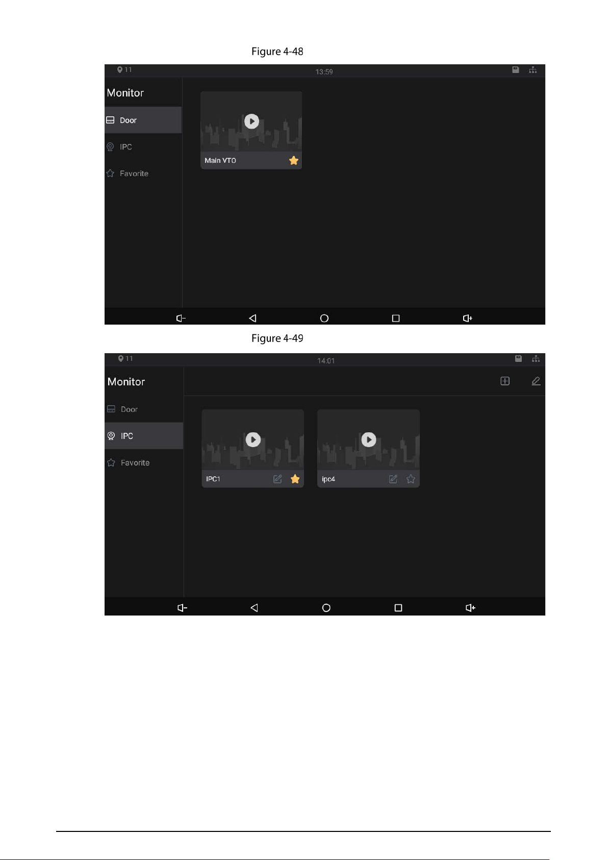
4.9.1 Watching Monitoring Videos
Tap .
On the indoor monitor, you can watch videos captured by door stations and IP cameras. You can also
put door stations and IP cameras that you like into the Favorite folder by tapping at the lower
right corner of each device.
During the call with a door station, you can watch the real-time videos capture by door stations or IP
cameras.
46
Monitor (1)
Monitor (2)
47
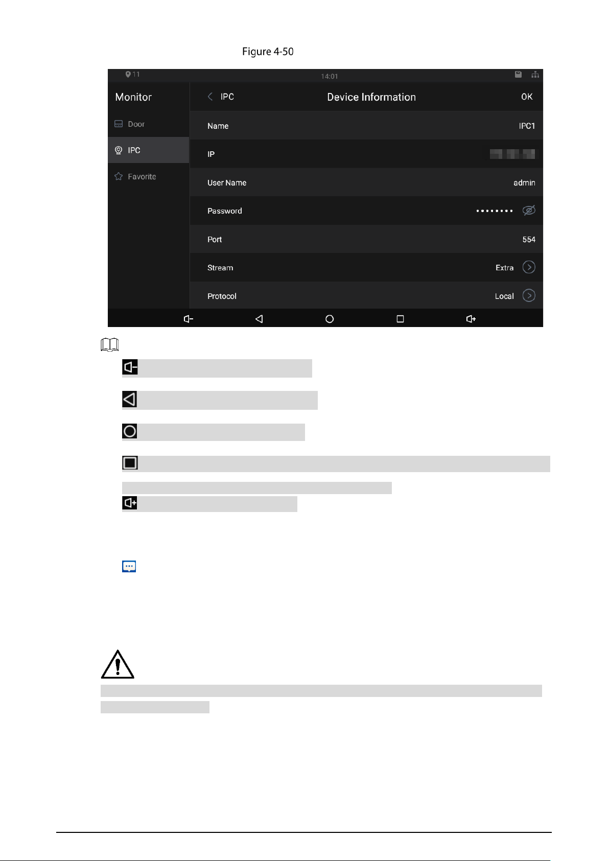
IPC information
: Tap the icon to turn down the volume.
: Tap the icon to go to the previous page.
: Tap the icon to go to the main menu.
: Tap the icon, and all thumbnails of interfaces you have opened will be displayed. Select an
interface and slide it to the left or right to close the interface.
: Tap the icon to turn up the volume.
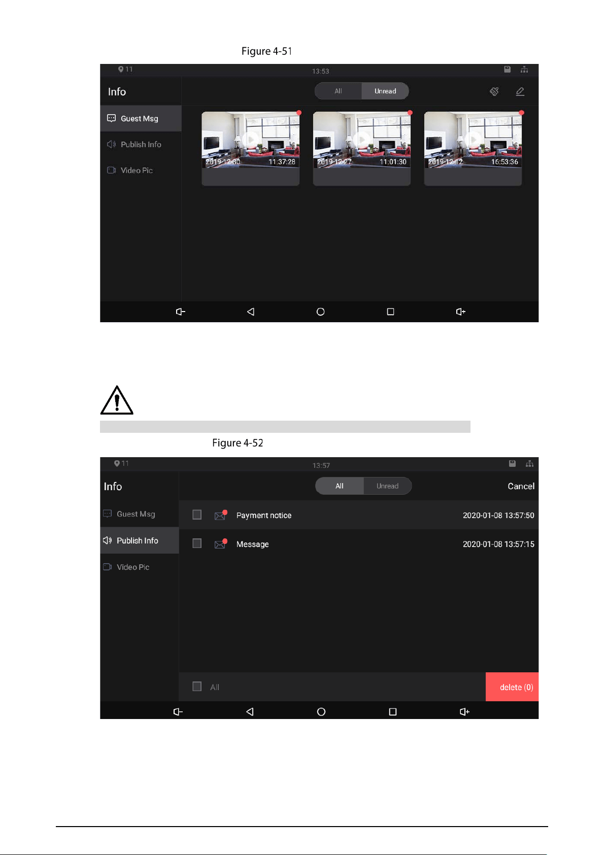
4.9.2 Checking Messages
Tap on the main menu, and then you can watch videos left by visitors, view snapshots and
public notices released by the management center, or delete videos and snapshots.
4.9.2.1 Guest Message
This function will be available when SD card is inserted in the indoor monitor, and all messages will
be stored in the SD card.
48
Guest message
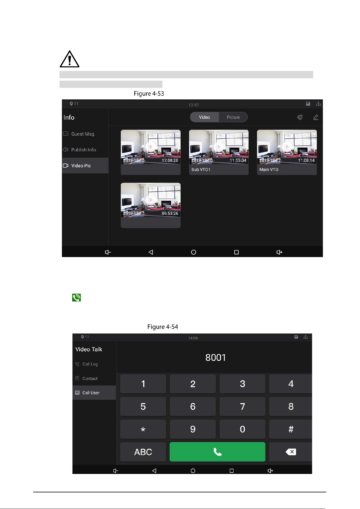
4.9.2.2 Publish Info
Public notices released by the management center are stored in the indoor monitor.
Viewing publish information
49
4.9.2.3 Video Pic
This function will be available when SD card is inserted in the indoor monitor, and all videos and
snapshots will be stored in the SD card.
Viewing video pictures
4.9.3 Making Calls
Tap , and then you can call other indoor monitors and the management center; and you can also
view call logs and your contacts on this interface. You can also call the indoor monitor from door
stations.
Making calls
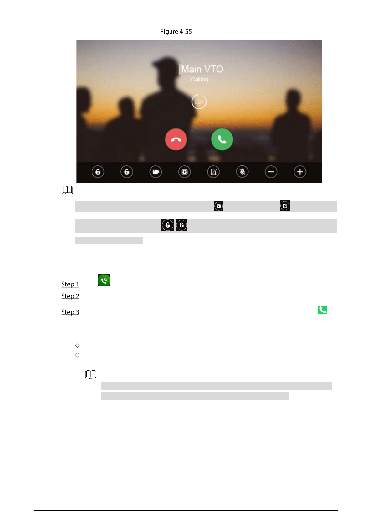
50
Calling
If SD card is not inserted, the video recording icon and snapshot icon cannot be used.
You can tap the unlock icon / to unlock doors. If the icons turn grey, the unlock
function cannot be used.
Call Residents through Dialing Numbers
Tap
Tap Call User.
Enter room number (room number you entered in the indoor monitor), and then tap .
If door station (VTO) works as SIP server, enter a room number.
If management platform like DSS Pro or DSS Express works as SIP server.
Call residents in your apartment or your building, enter a room number.
Call residents in other apartments and buildings, enter 1#1#101 for apartment 1 building 1
room 101.
If you call the extensions (101#1) from the main indoor monitor (101#0), just enter -1.
If you call the main indoor monitor from the extensions, just enter -0.
Call Residents through Contacts
You can also call residents through contacts.
Call through Call Logs
You can make calls through tapping call records.

51
Cybersecurity Recommendations
Cybersecurity is more than just a buzzword: it’s something that pertains to every device that is
connected to the internet. IP video surveillance is not immune to cyber risks, but taking basic steps
toward protecting and strengthening networks and networked appliances will make them less
susceptible to attacks. Below are some tips and recommendations on how to create a more secured
security system.
Mandatory actions to be taken for basic device network security:
1. Use Strong Passwords
Please refer to the following suggestions to set passwords:
The length should not be less than 8 characters;
Include at least two types of characters; character types include upper and lower case
letters, numbers and symbols;
Do not contain the account name or the account name in reverse order;
Do not use continuous characters, such as 123, abc, etc.;
Do not use overlapped characters, such as 111, aaa, etc.;
2. Update Firmware and Client Software in Time
According to the standard procedure in Tech-industry, we recommend to keep your device
(such as NVR, DVR, IP camera, etc.) firmware up-to-date to ensure the system is equipped
with the latest security patches and fixes. When the device is connected to the public
network, it is recommended to enable the “auto-check for updates” function to obtain
timely information of firmware updates released by the manufacturer.
We suggest that you download and use the latest version of client software.
"Nice to have" recommendations to improve your device network security:
1. Physical Protection
We suggest that you perform physical protection to device, especially storage devices. For
example, place the device in a special computer room and cabinet, and implement well-done
access control permission and key management to prevent unauthorized personnel from
carrying out physical contacts such as damaging hardware, unauthorized connection of
removable device (such as USB flash disk, serial port), etc.
2. Change Passwords Regularly
We suggest that you change passwords regularly to reduce the risk of being guessed or cracked.
3. Set and Update Passwords Reset Information Timely
The device supports password reset function. Please set up related information for password
reset in time, including the end user’s mailbox and password protection questions. If the
information changes, please modify it in time. When setting password protection questions, it is
suggested not to use those that can be easily guessed.
4. Enable Account Lock
The account lock feature is enabled by default, and we recommend you to keep it on to
guarantee the account security. If an attacker attempts to log in with the wrong password
several times, the corresponding account and the source IP address will be locked.
5. Change Default HTTP and Other Service Ports
We suggest you to change default HTTP and other service ports into any set of numbers
between 1024~65535, reducing the risk of outsiders being able to guess which ports you are
using.

52
6. Enable HTTPS
We suggest you to enable HTTPS, so that you visit Web service through a secure communication
channel.
7. MAC Address Binding
We recommend you to bind the IP and MAC address of the gateway to the device, thus reducing
the risk of ARP spoofing.
8. Assign Accounts and Privileges Reasonably
According to business and management requirements, reasonably add users and assign a
minimum set of permissions to them.
9. Disable Unnecessary Services and Choose Secure Modes
If not needed, it is recommended to turn off some services such as SNMP, SMTP, UPnP, etc., to
reduce risks.
If necessary, it is highly recommended that you use safe modes, including but not limited to the
following services:
SNMP: Choose SNMP v3, and set up strong encryption passwords and authentication
passwords.
SMTP: Choose TLS to access mailbox server.
FTP: Choose SFTP, and set up strong passwords.
AP hotspot: Choose WPA2-PSK encryption mode, and set up strong passwords.
10. Audio and Video Encrypted Transmission
If your audio and video data contents are very important or sensitive, we recommend that you
use encrypted transmission function, to reduce the risk of audio and video data being stolen
during transmission.
Reminder: encrypted transmission will cause some loss in transmission efficiency.
11. Secure Auditing
Check online users: we suggest that you check online users regularly to see if the device is
logged in without authorization.
Check device log: By viewing the logs, you can know the IP addresses that were used to log
in to your devices and their key operations.
12. Network Log
Due to the limited storage capacity of the device, the stored log is limited. If you need to save
the log for a long time, it is recommended that you enable the network log function to ensure
that the critical logs are synchronized to the network log server for tracing.
13. Construct a Safe Network Environment
In order to better ensure the safety of device and reduce potential cyber risks, we recommend:
Disable the port mapping function of the router to avoid direct access to the intranet
devices from external network.
The network should be partitioned and isolated according to the actual network needs. If
there are no communication requirements between two sub networks, it is suggested to
use VLAN, network GAP and other technologies to partition the network, so as to achieve
the network isolation effect.
Establish the 802.1x access authentication system to reduce the risk of unauthorized access
to private networks.
Enable IP/MAC address filtering function to limit the range of hosts allowed to access the
device.