Loading ...
Loading ...
Loading ...
IMPORTANT:Yourtractoris shippedwithmotoroil in theengine.
However,you MUSTcheckthe oil levelbeforeoperating.Referto the
Service& Maintenancesectionfor instructionson checkingtheoil
level.
Attaching the Battery Cables
CALIFORNIA PROPOSITION 65
Batteryposts,terminals,andrelatedaccessoriescontainleadand
leadcompounds,chemicalsknownto the Stateof Californiato
causecancerand reproductiveharm.Washhandsafter handling.
Whenattachingbatterycables,alwaysconnectthe POSITIVE(Red)
wireto its terminalfirst,followedby the NEGATIVE(Black)wire.
Forshippingreasons,bothbatterycables on yourequipmentmay
havebeen left disconnectedfrom the terminalsat the factory.To
connectthe batterycables,proceedasfollows:
NOTE:Thepositivebatteryterminalis markedPos.(+).The negative
batteryterminalis markedNeg. (-).
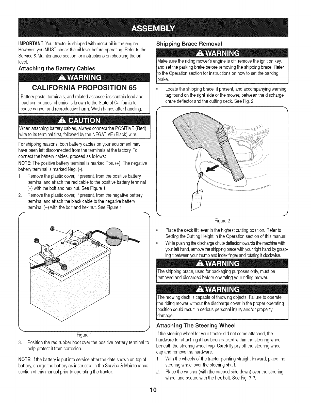
1. Removethe plasticcover,if present,fromthe positivebattery
terminaland attachthe redcableto the positivebatteryterminal
(+)withthe bolt andhexnut.See Figure1.
2. Removethe plasticcover,if present,fromthe negativebattery
terminaland attachthe black cableto the negativebattery
terminal(-) withthe bolt andhex nut.SeeFigure1.
f
J
Figure1
3. Positionthe red rubber boot over the positivebatteryterminalto
helpprotectit from corrosion.
NOTE:If thebatteryis put into serviceafter the dateshownon topof
battery,chargethe batteryas instructedinthe Service & Maintenance
sectionof this manualprior to operatingthe tractor.
Shipping Brace Removal
Makesurethe ridingmower'sengineis off, removetheignitionkey,
andset the parkingbrakebeforeremovingthe shippingbrace. Refer
Itothe Operationsectionfor instructionson howto setthe parking
lbrake.
• Locatethe shippingbrace, if present,andaccompanyingwarning
tag foundonthe rightsideof the mower,betweenthe discharge
chutedeflectorand the cuttingdeck. See Fig. 2.
//
Figure2
Placethe deck lift leverinthe highestcuttingposition.Referto
SettingtheCuttingHeightin the Operationsectionof thismanual.
Whilepushingthedischargechuteddlectortowardsthemachinewith
yourlefthand,removetheshippingbracewithyourrighthandbygrasp-
ingitbetweenyourthumbandindexfingerandrotatingitclockwise.
The shippingbrace,usedfor packagingpurposesonly,mustbe
removedand discardedbeforeoperatingyour ridingmower.
The mowingdeck iscapableof throwingobjects. Failureto operate
the ridingmowerwithoutthe dischargecoverin the properoperating
Ipositioncould resultin seriouspersonalinjuryand/orproperty
ldamage.
Attaching The Steering Wheel
Ifthe steeringwheelfor yourtractordid notcomeattached,the
hardwarefor attachingit has beenpackedwithinthe steeringwheel,
beneaththe steeringwheelcap. Carefullypry off the steeringwheel
cap and removethe hardware.
1. Withthe wheelsof the tractorpointingstraightforward,placethe
steeringwheeloverthe steeringshaft.
2. Placethe washer(withthe cuppedsidedown)overthe steering
wheeland securewith the hex bolt. See Fig.3-3.
10
Loading ...
Loading ...
Loading ...