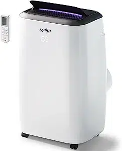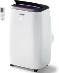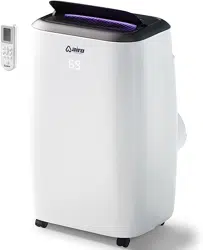
PORTABLE AIR CONDITIONER
AC08MWS
AC10MWS
AC12MWS
AC12HMWS
AC14MWS
AC14HMWS
MODELS
With our thanks to you, we sincerely hope you will enjoy your ™ portable air
conditioner trouble-free in the years ahead. If you do have any questions
however, regarding this manual, installation or operation, please know that we
are always here to assist you with any concern!
1-(800) 838-1198
airocomfort.com/contact
support@airocomfort.com
14
reaching
airo comfort

AC08MWS
AC10MWS
AC12MWS
AC12HMWS
AC14MWS
AC14HMWS
8,000
10,000
12,000
12,000
14,000
14,000
5,000
6,000
8,000
8,000
10,000
10,000
BTU MODEL SACC
SQ FT
COVERAGE
200
350
450
450
600
600
Heat
option
Heat
option
PORTABLE AIR CONDITIONER MODELS OVERVIEW
BEFORE YOU START
Take a few moments register your product at airocomfort.com/register.
You’ll always know about the latest updates, coupons, and other relevant
information. Although greatly appreciated, product registration is not
required to activate any warranty.
BEFORE FIRST USE
To prevent any internal damage, it is very important to keep your airo
comfort™ air conditioner standing upright and outside the box for 24
HOURS before plugging it in.
SAVE THIS MANUAL FOR FUTURE REFENCE
TABLE OF CONTENTS
Important Safety Instructions......................................................................... 2
Housing & Parts Description ............................................................................ 3
Assembly Preparation..........................................................................................4
Window Installation 1 ........................................................................................... 5
Window Installation 2 .......................................................................................... 7
Control Panel and Remote Functions .......................................................... 8
Operation..................................................................................................................... 9
Water Drainage.......................................................................................................10
Maintenance............................................................................................................... 11
Troubleshooting......................................................................................................12
Warranty.....................................................................................................................13
Reaching airo comfort™......................................................................................14
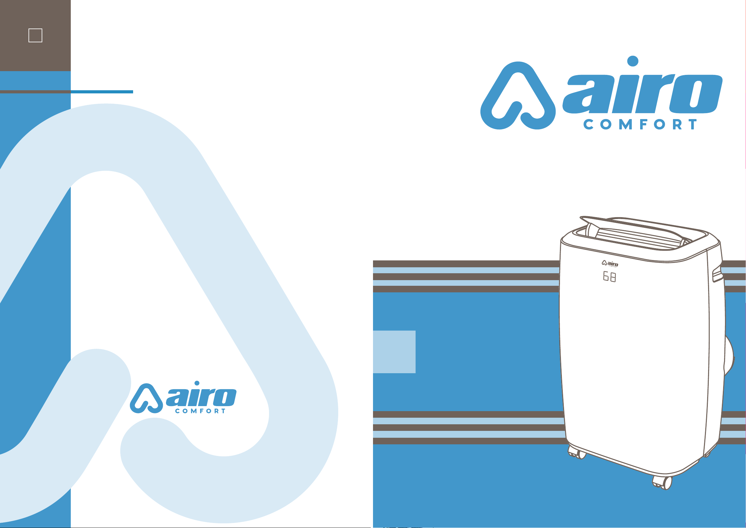
SIMPLY RELIABLE.
COOLING,HEATING & HUMIDITY SOLUTIONS FOR YOUR HOME
AC08MWS
AC10MWS
AC12MWS
AC12HMWS
AC14MWS
AC14HMWS
8,000
10,000
12,000
12,000
14,000
14,000
5,000
6,000
8,000
8,000
10,000
10,000
BTU MODEL SACC
SQ FT
COVERAGE
200
350
450
450
600
600
Heat
option
Heat
option
PORTABLE AIR CONDITIONER MODELS OVERVIEW
BEFORE YOU START
Take a few moments register your product at airocomfort.com/register.
You’ll always know about the latest updates, coupons, and other relevant
information. Although greatly appreciated, product registration is not
required to activate any warranty.
BEFORE FIRST USE
To prevent any internal damage, it is very important to keep your airo
comfort™ air conditioner standing upright and outside the box for 24
HOURS before plugging it in.
SAVE THIS MANUAL FOR FUTURE REFENCE
TABLE OF CONTENTS
Important Safety Instructions......................................................................... 2
Housing & Parts Description ............................................................................ 3
Assembly Preparation..........................................................................................4
Window Installation 1 ........................................................................................... 5
Window Installation 2 .......................................................................................... 7
Control Panel and Remote Functions .......................................................... 8
Operation..................................................................................................................... 9
Water Drainage.......................................................................................................10
Maintenance............................................................................................................... 11
Troubleshooting......................................................................................................12
Warranty.....................................................................................................................13
Reaching airo comfort™......................................................................................14
SIMPLY RELIABLE.
COOLING,HEATING & HUMIDITY SOLUTIONS FOR YOUR HOME
2
When using your airo comfort™ 14,000 BTU Portable Air Conditioner, basic safety precautions should
always be followed to reduce the risk of fire, electrical shock, and/or injury to persons. Please read all
assembly and operation Instructions. Failing to do so may result in incorrect operation, damage or
even personal injury!
THIS SYMBOL INDICATES INSTRUCTIONS THAT MUST BE OBSERVED.
FAILING TO DO SO MAY RESULT IN SERIOUS INJURY OR DEATH.
• The appliance is for indoor use only.
• Use this appliance only for its intended purpose as described in this manual.
• Visually inspect it to ensure there is no damage. If you suspect the appliance has been damaged,
contact a technician or our customer service team for assistance.
• Installation must be performed according to the installation instructions. Improper installation can
cause water leakage, electrical shock, or fire.
• Use only the included accessories, parts, and specified tools for installation. Otherwise, it may cause
water leakage, electrical shock, fire, injury, or property damage.
• Make sure that the outlet you are using is grounded and has the appropriate voltage. The power cord
is equipped with a three-prong grounding plug to protect against shock. Voltage information can be
found on the side of the unit, behind the grille.
• Install and always keep the unit on a flat, sturdy surface. Failure to do so could result in damage or
excessive noise and vibration.
• DO NOT install the air conditioner in a wet room, such as a bathroom or laundry room. Too much
exposure to water can cause electrical components to short circuit.
• DO NOT install the air conditioner in a place that may be exposed to combustible gas, as this could
cause fire.
• The appliance must be kept free from obstruction to ensure proper function and to mitigate safety
hazards.
• DO NOT modify the length of the power cord or use an extension cord to power the unit.
• DO NOT share a single outlet with other electrical appliances. An improper power supply can cause
fire or electrical shock.
• Turn o the appliance when not in use.
• The air conditioner has wheels to facilitate moving. Do not use the wheels on thick carpet or to roll
over objects, as these could cause tipping.
• DO NOT operate the air conditioner if it has been dropped or damaged.
• If the air conditioner is knocked over during use, turn it o and unplug it from the main power supply
immediately.
• DO NOT touch the air conditioner with wet hands.
• DO NOT allow children to play with the air conditioner. Children must be supervised around the air
conditioner at all times.
• In a thunderstorm, power o the air conditioner to avoid damage due to lightning.
important
safety instructions
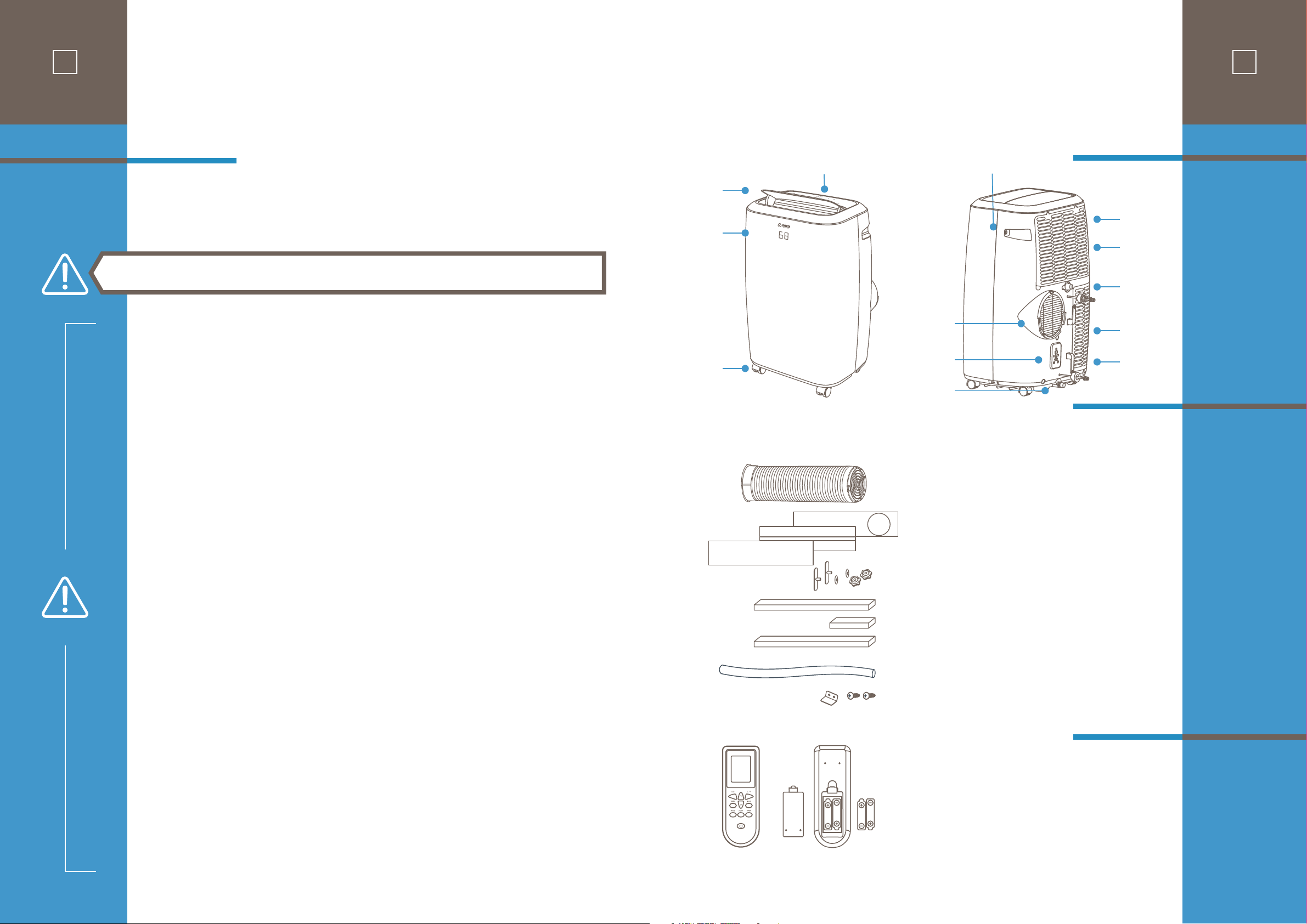
Housing
Functions
and
Connections
Installation
Connectors
3
QUANTITY
Vent Tube Assembly .............................................. 1
Window Sliders .......................................................... 3
Window Slider Lock Kit ...................................... 1
Foam Seal A (with adhesive) ........................... 1
Foam Seal B (with adhesive) ............................ 2
Foam Seal C ................................................................... 1
Drain Hose ..................................................................... 1
Security Bracket and 2 Screws ....................... 1
Remote Control ......................................................... 1
Batteries .......................................................................... 2
Air
Outlet
Door
Control Panel
Front
Panel
Wheels
Handles
Air Filter
Upper Air
Intake
Upper Drain
Outlet
Lower Air
Intake
Power
Plug Socket
Main Air
Outlet Connect
to Vent Tube
Power Cord
Wrap
Bottom Tray
Drain Outlet
housing &
parts description
Accessories
2
When using your airo comfort™ 14,000 BTU Portable Air Conditioner, basic safety precautions should
always be followed to reduce the risk of fire, electrical shock, and/or injury to persons. Please read all
assembly and operation Instructions. Failing to do so may result in incorrect operation, damage or
even personal injury!
THIS SYMBOL INDICATES INSTRUCTIONS THAT MUST BE OBSERVED.
FAILING TO DO SO MAY RESULT IN SERIOUS INJURY OR DEATH.
• The appliance is for indoor use only.
• Use this appliance only for its intended purpose as described in this manual.
• Visually inspect it to ensure there is no damage. If you suspect the appliance has been damaged,
contact a technician or our customer service team for assistance.
• Installation must be performed according to the installation instructions. Improper installation can
cause water leakage, electrical shock, or fire.
• Use only the included accessories, parts, and specified tools for installation. Otherwise, it may cause
water leakage, electrical shock, fire, injury, or property damage.
• Make sure that the outlet you are using is grounded and has the appropriate voltage. The power cord
is equipped with a three-prong grounding plug to protect against shock. Voltage information can be
found on the side of the unit, behind the grille.
• Install and always keep the unit on a flat, sturdy surface. Failure to do so could result in damage or
excessive noise and vibration.
• DO NOT install the air conditioner in a wet room, such as a bathroom or laundry room. Too much
exposure to water can cause electrical components to short circuit.
• DO NOT install the air conditioner in a place that may be exposed to combustible gas, as this could
cause fire.
• The appliance must be kept free from obstruction to ensure proper function and to mitigate safety
hazards.
• DO NOT modify the length of the power cord or use an extension cord to power the unit.
• DO NOT share a single outlet with other electrical appliances. An improper power supply can cause
fire or electrical shock.
• Turn o the appliance when not in use.
• The air conditioner has wheels to facilitate moving. Do not use the wheels on thick carpet or to roll
over objects, as these could cause tipping.
• DO NOT operate the air conditioner if it has been dropped or damaged.
• If the air conditioner is knocked over during use, turn it o and unplug it from the main power supply
immediately.
• DO NOT touch the air conditioner with wet hands.
• DO NOT allow children to play with the air conditioner. Children must be supervised around the air
conditioner at all times.
• In a thunderstorm, power o the air conditioner to avoid damage due to lightning.
important
safety instructions
Housing
Functions
and
Connections
Installation
Connectors
3
QUANTITY
Vent Tube Assembly .............................................. 1
Window Sliders .......................................................... 3
Window Slider Lock Kit ...................................... 1
Foam Seal A (with adhesive) ........................... 1
Foam Seal B (with adhesive) ............................ 2
Foam Seal C ................................................................... 1
Drain Hose ..................................................................... 1
Security Bracket and 2 Screws ....................... 1
Remote Control ......................................................... 1
Batteries .......................................................................... 2
Air
Outlet
Door
Control Panel
Front
Panel
Wheels
Handles
Air Filter
Upper Air
Intake
Upper Drain
Outlet
Lower Air
Intake
Power
Plug Socket
Main Air
Outlet Connect
to Vent Tube
Power Cord
Wrap
Bottom Tray
Drain Outlet
housing &
parts description
Accessories
4
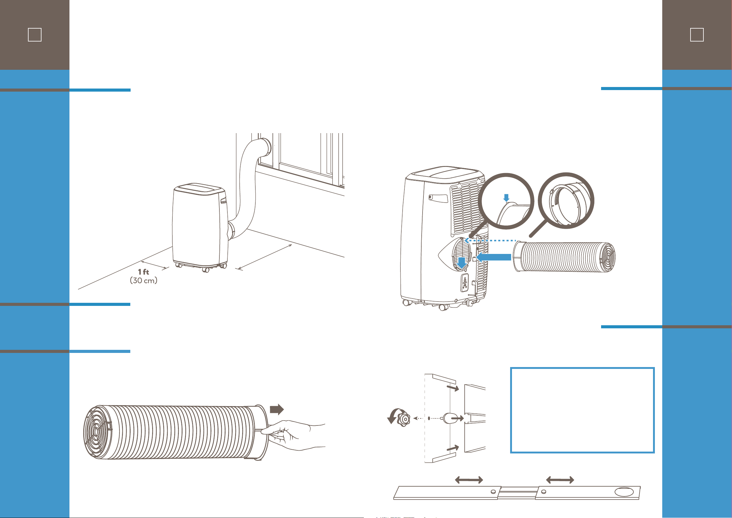
Make sure that you install your unit on an even surface for minimal noise and vibration.
The unit must be installed near a grounded plug and the Bottom Tray Drain Outlet (on the back of the
unit) must be accessible.
• Medium Philips screwdriver
• Tape measure or ruler
• Knife or scissors
• Saw (optional, to shorten Window Slider Adapter for narrow windows)
Begin with taking a small portion of the vent tube end and extend it out by grasping end with your fingers
and pulling out and away.
Before
You
Begin
Tools
Needed
STEP ONE:
Preparing
the Vent Tube
Assembly
2.6 ft - 3.0 ft
(80 cm - 90 cm)
Minimum unit to wall surface distance
assembly
preparation
1
Alignment
Tab
1
2
STEP TWO:
Installing the
Vent Hose
Assembly to the
Unit
STEP THREE:
Preparing the
Adjustable
Window Slider
5
Insert the Unit Adapter (the Unit Adapter Tab should remain right-side up) of the Vent Tube assembly
into the lower groove of the air outlet while the tab on the adapter ring is aligned with the air outlet.
Slide down the Unit Adapter. The tube will slide in and lock in place.
13 2
A B
Underside
View
Based on the size of your window, adjust the size of the Window Slider.
If the width of the window is short use slider section “A” and cut to size, sections “A” and “B” for
mid-length or all three sections “A” and “B” and “C” for extra length if needed for vertical installations.
Assembly steps:
• Start with slider section (A) and insert a T-screw
mount (1) through the underside hole (2) and screw on
locking knob (3) VERY LOOSELY.
• Slide the assembled section (A) around the end of
section (B) with the T-screw sliding into the center
channel groove.
• Repeat for section (C) if needed and adjust completed
slider length to window measurement.
• Tighten locking knobs to secure panel connection.
C B A
Topside View
4
Make sure that you install your unit on an even surface for minimal noise and vibration.
The unit must be installed near a grounded plug and the Bottom Tray Drain Outlet (on the back of the
unit) must be accessible.
• Medium Philips screwdriver
• Tape measure or ruler
• Knife or scissors
• Saw (optional, to shorten Window Slider Adapter for narrow windows)
Begin with taking a small portion of the vent tube end and extend it out by grasping end with your fingers
and pulling out and away.
Before
You
Begin
Tools
Needed
STEP ONE:
Preparing
the Vent Tube
Assembly
2.6 ft - 3.0 ft
(80 cm - 90 cm)
Minimum unit to wall surface distance
assembly
preparation
1
Alignment
Tab
1
2
STEP TWO:
Installing the
Vent Hose
Assembly to the
Unit
STEP THREE:
Preparing the
Adjustable
Window Slider
5
Insert the Unit Adapter (the Unit Adapter Tab should remain right-side up) of the Vent Tube assembly
into the lower groove of the air outlet while the tab on the adapter ring is aligned with the air outlet.
Slide down the Unit Adapter. The tube will slide in and lock in place.
13 2
A B
Underside
View
Based on the size of your window, adjust the size of the Window Slider.
If the width of the window is short use slider section “A” and cut to size, sections “A” and “B” for
mid-length or all three sections “A” and “B” and “C” for extra length if needed for vertical installations.
Assembly steps:
• Start with slider section (A) and insert a T-screw
mount (1) through the underside hole (2) and screw on
locking knob (3) VERY LOOSELY.
• Slide the assembled section (A) around the end of
section (B) with the T-screw sliding into the center
channel groove.
• Repeat for section (C) if needed and adjust completed
slider length to window measurement.
• Tighten locking knobs to secure panel connection.
C B A
Topside View
Foam seal A
Foam seal B
Foam seal B
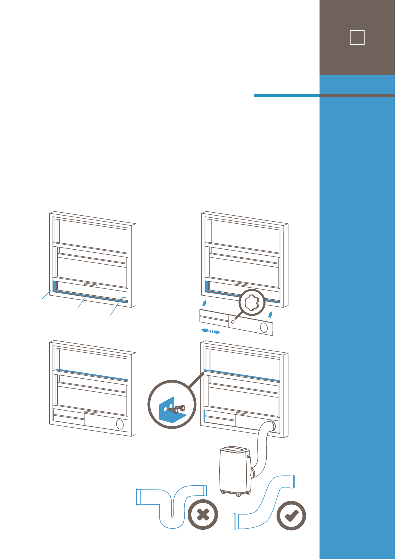
NOTE: Once the Vent Tube assembly and Adjustable Window Slider are prepared, choose from
one of the following two installation methods.
1. Cut Foam Seal A and B strips to the proper lengths and remove the adhesive backing. Attach them to
the window sash and frame as shown.
2. Insert the Window Slider assembly into the window opening.
3. Cut the non-adhesive Foam Seal C strip to match the width of the window. Insert the seal between the
glass and the window frame to prevent air and insects from getting into the room.
4. If desired, install the optional security bracket with 2 screws as shown.
5. Insert the tube Window Slider Adapter into the hole of the Window Slider.
window
installation 1
Method 1:
Sliding Window
Installation
OPTIONAL
Foam seal C
1 2
3 4
6
1. Cut Foam Seal A and B strips to the proper lengths and remove the adhesive backing. Attach
them to the window sash and frame as shown.
2. Insert the Window Slider assembly into the window opening.
3. Cut the non-adhesive Foam Seal C strip to match the width of the window. Insert the seal
between the glass and the window frame to prevent air and insects from getting into the room.
4. If desired, install the optional security bracket with 2 screws as shown.
5. Insert the tube Window Slider Adapter into the hole of the Window Slider.
Foam seal A
Foam seal B
Foam seal B
1
2
Foam seal C
3
OPTIONAL
4
window
installation 2
Method 2:
Hung Window
Installation
7
Foam seal A
Foam seal B
Foam seal B
NOTE: Once the Vent Tube assembly and Adjustable Window Slider are prepared, choose from
one of the following two installation methods.
1. Cut Foam Seal A and B strips to the proper lengths and remove the adhesive backing. Attach them to
the window sash and frame as shown.
2. Insert the Window Slider assembly into the window opening.
3. Cut the non-adhesive Foam Seal C strip to match the width of the window. Insert the seal between the
glass and the window frame to prevent air and insects from getting into the room.
4. If desired, install the optional security bracket with 2 screws as shown.
5. Insert the tube Window Slider Adapter into the hole of the Window Slider.
window
installation 1
Method 1:
Sliding Window
Installation
OPTIONAL
Foam seal C
1 2
3 4
6
1. Cut Foam Seal A and B strips to the proper lengths and remove the adhesive backing. Attach
them to the window sash and frame as shown.
2. Insert the Window Slider assembly into the window opening.
3. Cut the non-adhesive Foam Seal C strip to match the width of the window. Insert the seal
between the glass and the window frame to prevent air and insects from getting into the room.
4. If desired, install the optional security bracket with 2 screws as shown.
5. Insert the tube Window Slider Adapter into the hole of the Window Slider.
Foam seal A
Foam seal B
Foam seal B
1
2
Foam seal C
3
OPTIONAL
4
window
installation 2
Method 2:
Hung Window
Installation
7
Confirm that the vent tube has been mounted properly.
• When using functions on cooling and dehumidifying, keep an interval of at least 3 minutes
between each ON/OFF.
• Be sure wall socket provides standard 110-115V AC, 60Hz use.
• Do not share one socket with other appliances.
• Press the “MODE” button until the “Cool” or “Heat” (for models with Heat) icon appears.
• Press the “DOWN” or “UP” button to select a desired room temperature between 61-88
°F
(16-31
°C
).
• Press the “SPEED” button to select fan speed.
• Press the “MODE” button until the “Dehumidify” icon appears.
• The unit will automatically set the selected temperature to current room temperature minus
2°C/4°F
.
• The unit will automatically set the fan LOW speed.
IMPORTANT: Please read manual section “WATER DREAINAGE” regarding options for draining
collected water from the unit.
• Press the “MODE” button until the “Fan” icon appears.
• Press the “SPEED” button to select fan speed.
Timer ON setting:
• When the air-conditioner is OFF, press the “TIMER” button and select a desired ON time using the
“UP” and “DOWN” buttons.
• Confirm the selected time by pressing the “TIMER” button once. (If you do not confirm, the TIMER
“ON” will not go into eect.)
• Selected ON time is displayed on the operation panel.
• ON time can be set to 0-24 hours in 1-hour increments.
Timer OFF setting:
• When the air-conditioner ON, press “TIMER” button and select a desired OFF time using the “UP” and
“DOWN” buttons.
• Confirm the selected time by pressing the “TIMER” button once. (If you do not confirm, the TIMER
“OFF” will not go into eect.)
• Selected OFF Time is displayed on the operation panel.
• OFF time can be set to 0-24 hours in 1-hour increments.
• After machine turns on, press this key ON REMOTE CONTROL and the louver will swing continuously
up and down. By pressing this button again, the movement will stop, and the louver remain in that
position.
• While in cooling mode, press the SLEEP key ON REMOTE CONTROL to set the temperature. It
increases
1°C/2°F
after an hour and at most increases
2°C/4°F
after 2 hours.
CAUTIONS
Cooling OR
Heating
Dehumidifying
Fan
Timer
Swing
(Flow Direction)
Sleep
9
operation
8
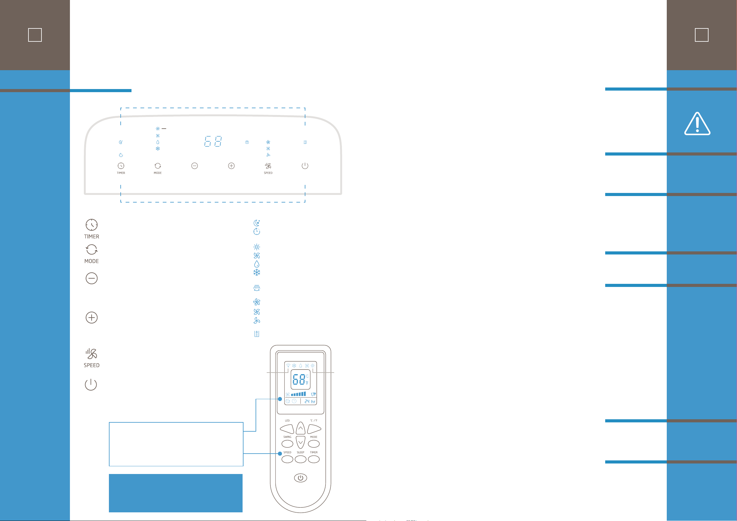
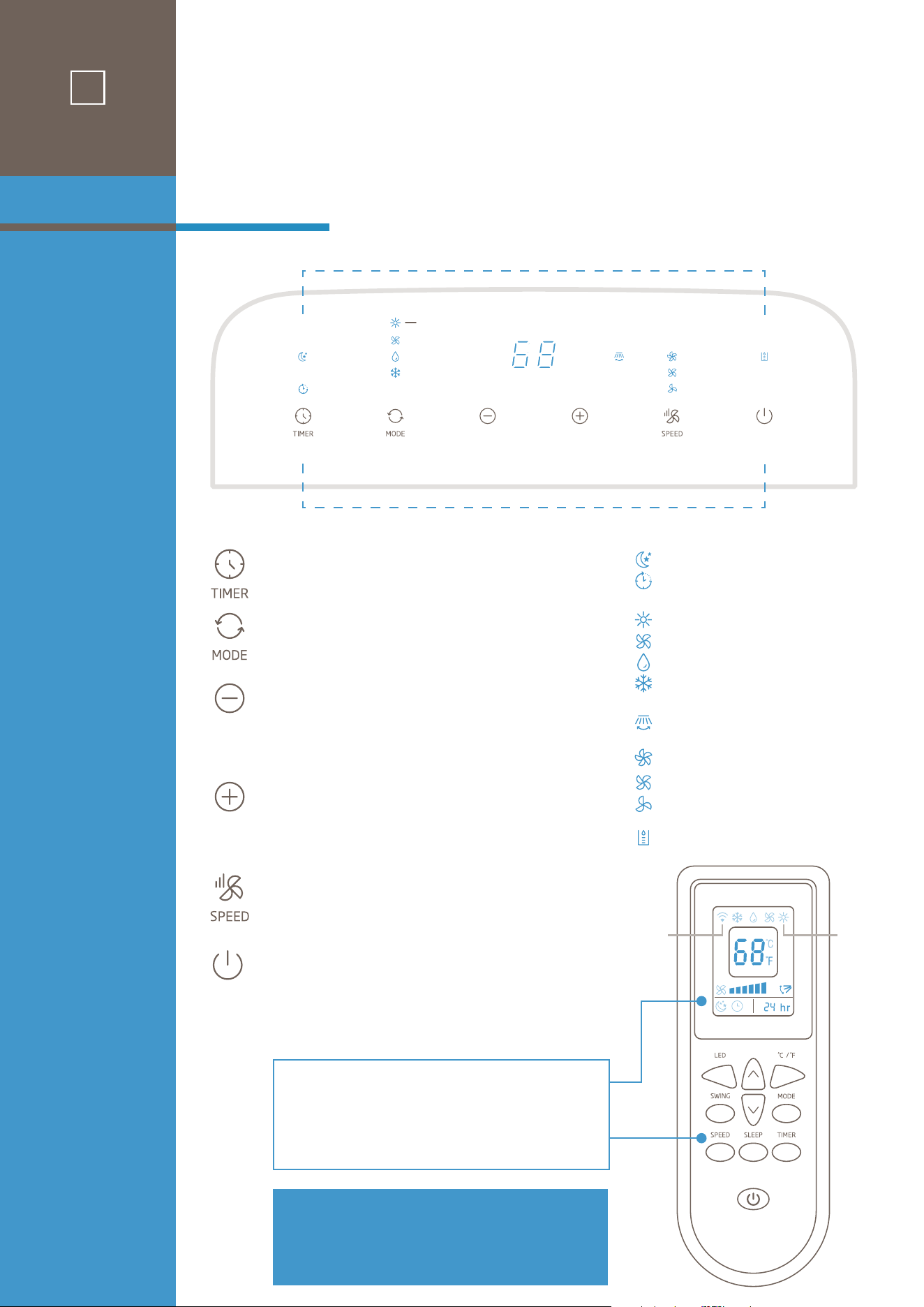
Buttons
and
Indicators
INDICATORS
BUTTONS
TIMER
Timer ON/OFF setting.
MODE
Select cooling, dehumidifying, fan or heat mode
DOWN
Set the temperature (or time), the temperature
(or time) will drop by 1°C/1°F (or 1 hour) with
each press.
UP
Set the indoor temperature (or time), the
temperature (or time) will rise by 1°C/1°F
(or 1 hour) with each press.
SPEED
Press to select either LOW, MEDIUM,
or HIGH fan speed.
POWER
Press to turn ON/OFF the unit.
Sleep (Run from remote)
Timer setting
Heat mode (Heat models only)
Fan mode
Dehumidify mode
Cool mode
Swing (Run from remote)
High fan
Mid fan
Low fan
Water full
Main unit control panel indicators also
apply to remote control display area.
Button functions on remote control operate
in same manner as main unit control panel.
control panel
& remote functions
HEAT MODELS ONLY
(Heat
models
only)
Signal
strength
Note:
• Do not drop the remote controller.
• Do not place the remote controller in a
location exposed to direct sunlight.

Confirm that the vent tube has been mounted properly.
• When using functions on cooling and dehumidifying, keep an interval of at least 3 minutes
between each ON/OFF.
• Be sure wall socket provides standard 110-115V AC, 60Hz use.
• Do not share one socket with other appliances.
• Press the “MODE” button until the “Cool” or “Heat” (for models with Heat) icon appears.
• Press the “DOWN” or “UP” button to select a desired room temperature between 61-88
°F
(16-31
°C
).
• Press the “SPEED” button to select fan speed.
• Press the “MODE” button until the “Dehumidify” icon appears.
• The unit will automatically set the selected temperature to current room temperature minus
2°C/4°F
.
• The unit will automatically set the fan LOW speed.
IMPORTANT: Please read manual section “WATER DREAINAGE” regarding options for draining
collected water from the unit.
• Press the “MODE” button until the “Fan” icon appears.
• Press the “SPEED” button to select fan speed.
Timer ON setting:
• When the air-conditioner is OFF, press the “TIMER” button and select a desired ON time using the
“UP” and “DOWN” buttons.
• Confirm the selected time by pressing the “TIMER” button once. (If you do not confirm, the TIMER
“ON” will not go into eect.)
• Selected ON time is displayed on the operation panel.
• ON time can be set to 0-24 hours in 1-hour increments.
Timer OFF setting:
• When the air-conditioner ON, press “TIMER” button and select a desired OFF time using the “UP” and
“DOWN” buttons.
• Confirm the selected time by pressing the “TIMER” button once. (If you do not confirm, the TIMER
“OFF” will not go into eect.)
• Selected OFF Time is displayed on the operation panel.
• OFF time can be set to 0-24 hours in 1-hour increments.
• After machine turns on, press this key ON REMOTE CONTROL and the louver will swing continuously
up and down. By pressing this button again, the movement will stop, and the louver remain in that
position.
• While in cooling mode, press the SLEEP key ON REMOTE CONTROL to set the temperature. It
increases
1°C/2°F
after an hour and at most increases
2°C/4°F
after 2 hours.
CAUTIONS
Cooling OR
Heating
Dehumidifying
Fan
Timer
Swing
(Flow Direction)
Sleep
9
operation
8
Buttons
and
Indicators
INDICATORS
BUTTONS
TIMER
Timer ON/OFF setting.
MODE
Select cooling, dehumidifying, fan or heat mode
DOWN
Set the temperature (or time), the temperature
(or time) will drop by 1°C/1°F (or 1 hour) with
each press.
UP
Set the indoor temperature (or time), the
temperature (or time) will rise by 1°C/1°F
(or 1 hour) with each press.
SPEED
Press to select either LOW, MEDIUM,
or HIGH fan speed.
POWER
Press to turn ON/OFF the unit.
Sleep (Run from remote)
Timer setting
Heat mode (Heat models only)
Fan mode
Dehumidify mode
Cool mode
Swing (Run from remote)
High fan
Mid fan
Low fan
Water full
Main unit control panel indicators also
apply to remote control display area.
Button functions on remote control operate
in same manner as main unit control panel.
control panel
& remote functions
HEAT MODELS ONLY
(Heat
models
only)
Signal
strength
Note:
• Do not drop the remote controller.
• Do not place the remote controller in a
location exposed to direct sunlight.
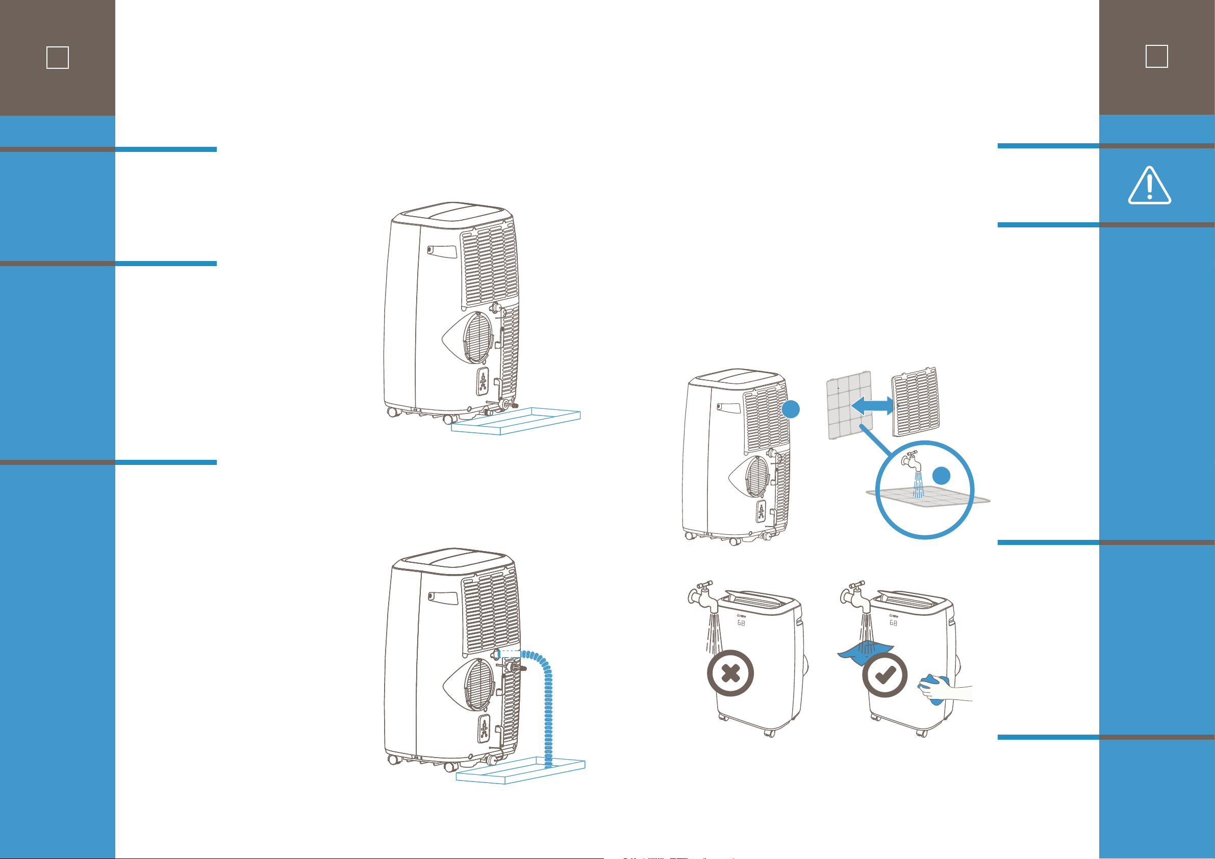
1) Before cleaning, be sure to disconnect the unit from any electric supply outlet;
2) Do not use gasoline or other chemicals to clean the unit;
3) Do not wash the unit directly;
4) If the conditioner is damaged, please contact the dealer or repair shop.
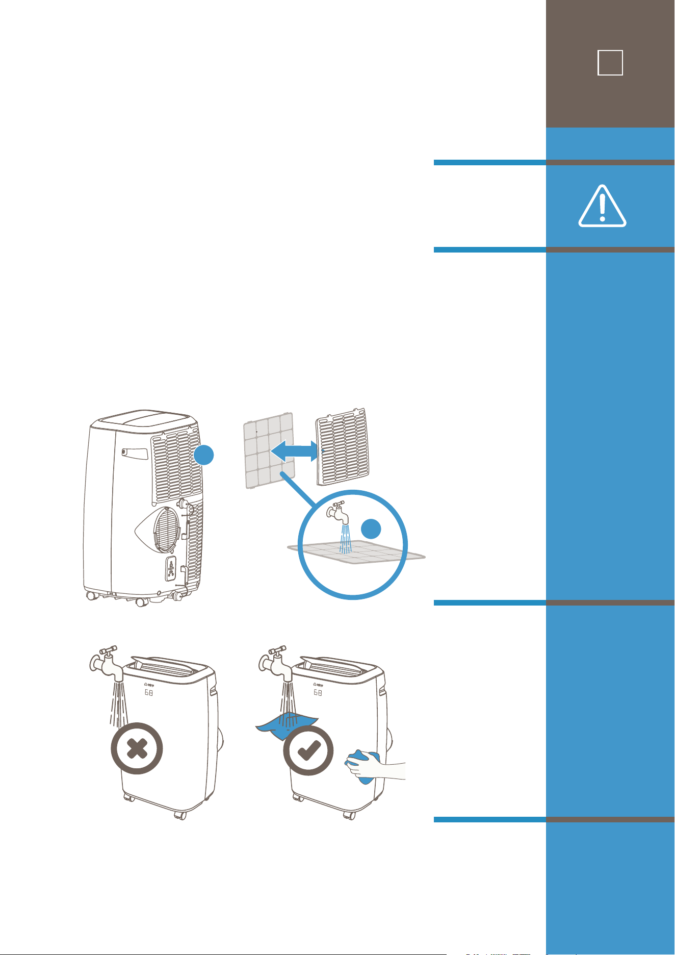
Cleaning the air filter every two weeks will keep in unit running in top condition with optimum
cooling eciency.
Before you clean: unplug the unit.
1. Open the upper air inlet grille and remove air filter.
2. Clean the air filter with mild or diluted detergent in lukewarm(40℃/104℉)water. Rinse well and
allow to air dry.
3. Return air filter to original position and replace the upper grille.
Clean housing surface with a mild detergent applied to wet cloth and wipe with a soft dry cloth.
1. Completely drain unit system according to steps found in the “WATER DRAINAGE” section.
2. Complete air filter cleaning as above.
3. Run unit in FAN mode for 15-20 minutes
4. Return drain spouts to snug position.
5. Clean housing as above and store unit.
Cleaning
the
Air Filter
Cleaning the
Housing
Storage
Maintenance
11
maintenance
3
2
1
Method 1:
Manual
Draining for
Cooling and
Dehumidifier
Mode
Method 2:
Continuous
Draining for
Dehumidifier
Mode
10
When there is excess water condensation inside
the unit during normal cooling operation, the air
conditioner stops running (the fan will continue
running) and the WATER FULL indicator illumi-
nates on the top control panel. This in dicates that
the collected water needs to be drained using
either of the following procedures:
With manual draining, both rear drain spout caps
are tightly sealed during normal operation. The
WATER FULL indicator will illuminate when the
internal water container is lled to the level
when it needs to be emptied.
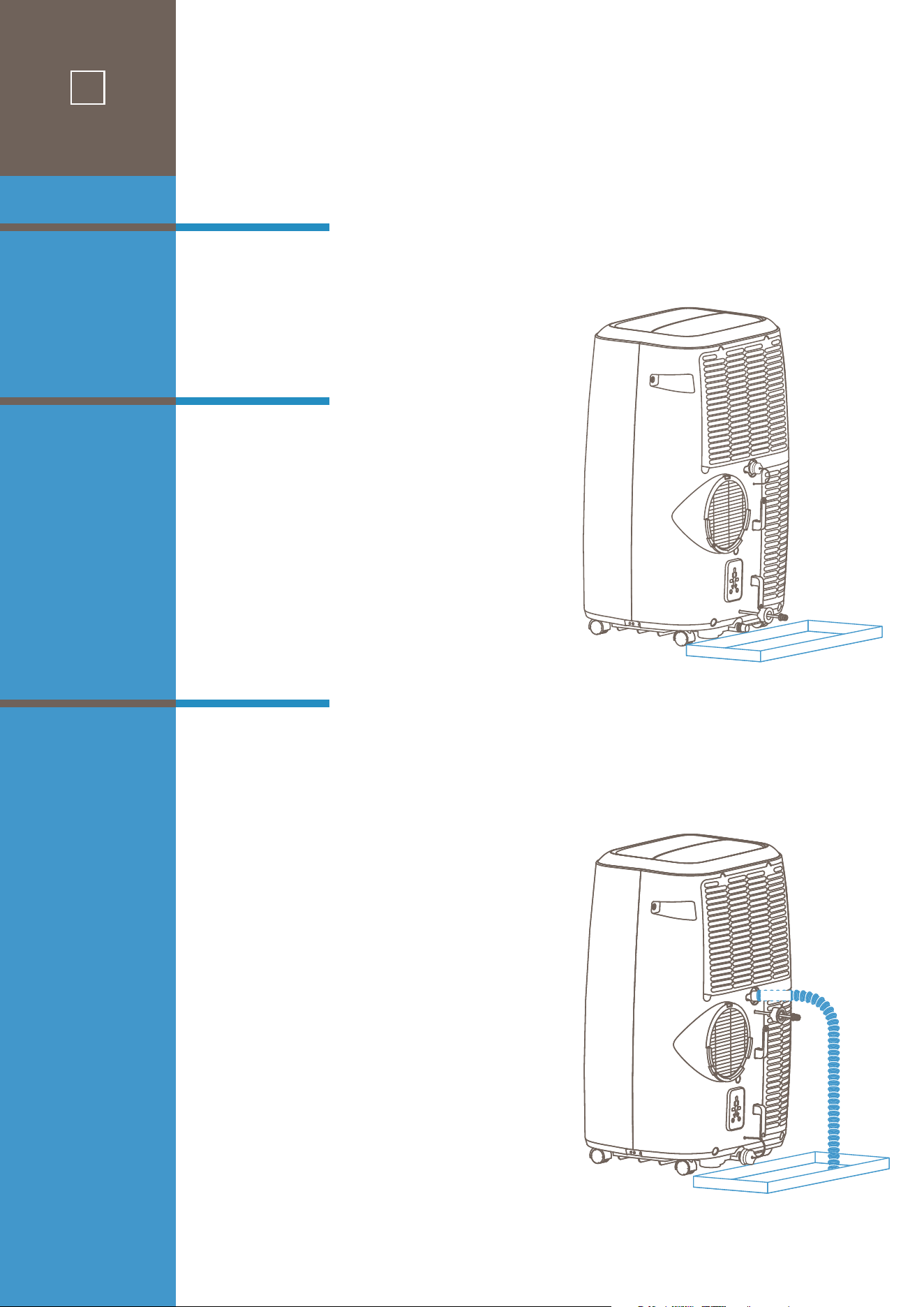
After turning the unit o, place a shallow pan
under the air conditioner as shown in the
diagram. Remove the lower drain spout rubber
cap and the water will drain from the unit.
Replace the rubber cap on to the drain spout and
power the unit on. The cooling function will
continue a few minutes after powering on.
This method is recommended for DEHUMIDIFIER
MODE. To drain water from the unit continuously
you will need to attach the provided drain hose
to the air conditioner. On the back side there is a
top and a bottom drain spout, each capped with
a rubber stopper. After turning unit o, remove
the top drain spout cap and insert the drain
hose. Position the other end of the drain hose to
a collector tray or towards a drain if that is avail-
able. (If you wish to utilize a drain in your home
you can connect your own standard ¾” hose cut
to the desired length needed.)
Keep in mind that the drain hose should not be
kinked or constrict water ow in any way. The
drain hose end and the collector tray must be at
a lower height than the upper drain spout
connection to the hose. Be sure to use a collector
container that is deep enough to hold at least a
liter of water as the dehumidifying process is
quite eective, and you wouldn’t want to empty
the tray unnecessarily often!
water
drainage
1) Before cleaning, be sure to disconnect the unit from any electric supply outlet;
2) Do not use gasoline or other chemicals to clean the unit;
3) Do not wash the unit directly;
4) If the conditioner is damaged, please contact the dealer or repair shop.
Cleaning the air filter every two weeks will keep in unit running in top condition with optimum
cooling eciency.
Before you clean: unplug the unit.
1. Open the upper air inlet grille and remove air filter.
2. Clean the air filter with mild or diluted detergent in lukewarm(40℃/104℉)water. Rinse well and
allow to air dry.
3. Return air filter to original position and replace the upper grille.
Clean housing surface with a mild detergent applied to wet cloth and wipe with a soft dry cloth.
1. Completely drain unit system according to steps found in the “WATER DRAINAGE” section.
2. Complete air filter cleaning as above.
3. Run unit in FAN mode for 15-20 minutes
4. Return drain spouts to snug position.
5. Clean housing as above and store unit.
Cleaning
the
Air Filter
Cleaning the
Housing
Storage
Maintenance
11
maintenance
3
2
1
Method 1:
Manual
Draining for
Cooling and
Dehumidifier
Mode
Method 2:
Continuous
Draining for
Dehumidifier
Mode
10
When there is excess water condensation inside
the unit during normal cooling operation, the air
conditioner stops running (the fan will continue
running) and the WATER FULL indicator illumi-
nates on the top control panel. This in dicates that
the collected water needs to be drained using
either of the following procedures:
With manual draining, both rear drain spout caps
are tightly sealed during normal operation. The
WATER FULL indicator will illuminate when the
internal water container is lled to the level
when it needs to be emptied.
After turning the unit o, place a shallow pan
under the air conditioner as shown in the
diagram. Remove the lower drain spout rubber
cap and the water will drain from the unit.
Replace the rubber cap on to the drain spout and
power the unit on. The cooling function will
continue a few minutes after powering on.
This method is recommended for DEHUMIDIFIER
MODE. To drain water from the unit continuously
you will need to attach the provided drain hose
to the air conditioner. On the back side there is a
top and a bottom drain spout, each capped with
a rubber stopper. After turning unit o, remove
the top drain spout cap and insert the drain
hose. Position the other end of the drain hose to
a collector tray or towards a drain if that is avail-
able. (If you wish to utilize a drain in your home
you can connect your own standard ¾” hose cut
to the desired length needed.)
Keep in mind that the drain hose should not be
kinked or constrict water ow in any way. The
drain hose end and the collector tray must be at
a lower height than the upper drain spout
connection to the hose. Be sure to use a collector
container that is deep enough to hold at least a
liter of water as the dehumidifying process is
quite eective, and you wouldn’t want to empty
the tray unnecessarily often!
water
drainage
12
troubleshooting
PR O BLEM PO S SIBL E CAUSE S SUGGESTED REMEDIES
1. Unit does not start when
pressing on/o button
Water full indicator lamp blinks Dump the water out of the water tank.
2. Not cool enough
3. Noisy
The ground is not level or not flat enough.
Place the unit on level ground if possible.
Sound from flowing refrigerant inside conditioner.
It is normal.
4. E0 Code
Room temperature sensor failed.
Replace room temperature sensor (the unit
can also work without replacement).
5. E1 Code
Condenser temperature sensor failed
Replace condenser temperature sensor.
6. E2 Code
Water ta
nk full when cooling.
Take o rubber stopper and empty the water.
7. E3 Code
Evaporator temperature sensor failed.
Replace evaporator temperature sensor.
8. E4 Code
Water tank full when heating.
Please empty the water tank.
Room temperature is lower than the
setting temperature. (Cooling mode)
Reset the temperature.
The doors or windows are not closed.
Make sure all the windows and doors are closed.
The
re are heat sources inside the room.
Remove the heat sources if possible
Vent tube
is not connected or blocked.
Connect or clean the vent tube.
.
Temperature setting is too high.
Reset the temperature.
Air inlet is blocked.
Clean the air inlet.
Specific information regarding
appliances with R32 refrigerant gas.
Thoroughly read all of the warnings.
• When defrosting and cleaning the appliance, do not use any tools other than those recommended by the manufacturing company.
• The appliance must be placed in an area without any continuously sources of ignition (open flames, gas, or electrical appliances in operation, etc).
• Do not puncture and do not burn.
• This appliance contains Yg (see rating label back of unit ) of R32 refrigerant gas.
• R32 is a refrigerant gas that complies with the European directives on the environment. Do not puncture any part of the refrigerant circuit.
• If the appliance is installed, operated, or stored in an unventilated area, the room must be designed to prevent to the accumulation of
refrigerant leaks resulting
in a risk of fire or explosion due to ignition of the refrigerant caused by electric heaters, stoves, or other sources of ignition.
• The appliance must be stored in such a way as to prevent mechanical failure.
• Individuals who operate or work on the refrigerant circuit must have the appropriate certification issued by an accredited organization that
ensures competence in handling refrigerants according to a specific evaluation recognized by associations in the industry.
• Repairs must be performed based on the recommendation from the manufacturing company. Maintenance and repairs that require the
assistance of other qualified personnel must be performed under the supervision of an individual specified in the use of flammable refrigerants.
Section 1
Initial Purchase
30-day Coverage
Section 2
1-Year Limited
Warranty
Coverage
13
warranty
Section 3
Compressor
3-year
Warranty
Warranty
Non-Coverage
Disclaimer of
Implied
Warranties
There are 3 areas of coverage for your AC14MWS Air Conditioner (Covered Equipment) which
are covered below:
IMPORTANT:
You must register your air conditioner purchase with
airo comfort™ within 60 days on
our web site (airocomfort.com/warranty) for the limited warranties described in sections 2 and 3 to
be in full compliance. Unregistered purchases may incur fees if service/repair is needed!
Defects in materials and workmanship of Covered Equipment that appear under normal use and mainte-
nance are fully covered for 30 days (and will include return shipping). This includes physical or working
operation defects if the product is in such condition upon removal from the packaging at purchase time.
Please report your concern directly to us either by calling our support number at 1-(800) 838-1198 or by
emailing
support@airocomfort.com to have the matter promptly resolved.
airo comfort™
warrants the Covered Equipment to be free from defects in materials and workman-
ship, and will repair or replace, at its option, ANY PART of Covered Equipment installed in residential
(not commercial) applications which fail in normal use and service within the applicable 1-year warranty
period. See above important notice on registering this product with
airo comfort™.
Please report your concern directly to us either by calling our support number at 1-(800) 838-1198 or by
emailing
support@airocomfort.com to have the matter promptly resolved.
airo comfort™
warrants the Internal compressor to be free from defects in materials and workman-
ship, and will repair or replace, at its option, ANY PART of compressor in Covered Equipment installed
in residential (not commercial) applications which fail in normal use and service within a 3-year warran-
ty period. See above important notice on registering this product with
airo comfort™.
Please report your concern directly to us either by calling our support number at 1-(800) 838-1198 or by
emailing
support@airocomfort.com to have the matter promptly resolved.
THIS WARRANTY DOES NOT COVER:
• Acts of God, such as fire, flood, hurricanes, earthquakes and tornadoes.
• Damage, accidental or otherwise, to the air conditioner while in the possession of a consumer not caused by a defect in
material or workmanship;
• Damage caused by misuse, tampering, or failure to follow the care and special handling provisions in the instructions.
• Damage to the finish of the case, or other appearance parts caused by wear.
• Damage caused by repairs or alterations to the product by anyone other than authorized by the manufacturer.
• Freight and Insurance cost for the 1-year warranty service and 3-year compressor warranty.
AIRO COMFORT, INC. IS NOT LIABLE FOR INCIDENTAL OR CONSEQUENTIAL DAMAGES OF ANY NATURE. ANY IMPLIED
WARRANTY OF MERCHANTABILITY OR FITNESS FOR A PARTICULAR PURPOSE ON THIS PRODUCT IS LIMITED IN DURA-
TION TO THE DURATION OF THIS WARRANTY.
Some jurisdictions do not allow the exclusion or limitation of incidental or consequential damages or limitations on how long an
applied warranty lasts, so the above limitations or exclusions may not apply to you. This warranty gives you specific legal rights,
and you also may have other rights which vary from jurisdiction to jurisdiction. This warranty applies only to the original
purchaser of this product from the original date of purchase.

PORTABLE AIR CONDITIONER
AC08MWS
AC10MWS
AC12MWS
AC12HMWS
AC14MWS
AC14HMWS
MODELS
With our thanks to you, we sincerely hope you will enjoy your ™ portable air
conditioner trouble-free in the years ahead. If you do have any questions
however, regarding this manual, installation or operation, please know that we
are always here to assist you with any concern!
1-(800) 838-1198
airocomfort.com/contact
support@airocomfort.com
14
reaching
airo comfort