
OWNER MANUAL
MANUALE D’USO
TX 4016
PX 4116
- UHF DIVERSITY WIRELESS
MICROPHONES
- RADIOMICROFONI UHF
“DIVERSITY”


INDEX
INDICE
ENGLISH
SAFETY PRECAUTIONS
DESCRIPTION
RX 4016 RECEIVER RACK MOUNTING
RX 4016 FRONT PANEL
RX 4016 REAR PANEL
RX 4016 OPERATION
TX 4000 TRANSMITTER / HANDHELD DYNAMIC MICROPHONE
PX 4100 BODY PACK TRANSMITTER
TX 4000 / PX 4100 TRANSMITTER OPERATION
FREQUENCIES
SPECIFICATIONS
ITALIANO
AVVERTENZE PER LA SICUREZZA
DESCRIZIONE
INSTALLAZIONE A RACK (19”) DEI RICEVITORI RX 4016
RX 4016 – PANNELLO FRONTALE
RX 4016 - PANNELLO POSTERIORE
FUNZIONAMENTO DEL RICEVITORE RX 4016
TRASMETTITORE AD IMPUGNATURA TX 4000 CON MICROFONO DINAMICO
TRASMETTITORE PER CINTURA PX 4100
FUNZIONAMENTO DEI TRASMETTITORI TX 4000 / PX 4100
FREQUENZE
DATI TECNICI
4
6
7
7
8
9
11
12
13
15
16
18
20
21
21
22
23
25
26
27
29
30

4
ENGLISH
IMPORTANT NOTES
Before connecting and using this product, please read this instruction manual carefully and
keep it on hand for future reference. The manual is to be considered an integral part of
this product and must accompany it when it changes ownership as a reference for correct
installation and use as well as for the safety precautions.
RCF S.p.A. will not assume any responsibility for the incorrect installation and / or use of
this product.
WARNING: To prevent the risk of fire or electric shock, never expose these products to
rain or humidity.
SAFETY PRECAUTIONS
1. All the precautions, in particular the safety ones, must be read with special attention, as
they provide important information.
2. Use the dedicated adapter only. Verify the mains voltage corresponds to the voltage shown
on the adapter rating plate and the adapter output voltage value and type (direct / alternating)
corresponds to the product input voltage. If not, please contact your RCF dealer.
Check also that the adapter has not been damaged due to possible clashes / hits or
overloads.
The mains voltage, which the adapter is connected to, is sufficiently high to involve a risk
of electrocution: pay attention during the connection (i.e. never do it with wet hands) and
never open the adapter.
Make sure that the adapter cable is not (or cannot be) stepped on or crushed by other
objects (pay particular attention to the cable part near the plug and the point where it
leads out from the adapter).
3. Make sure that no objects or liquids can get into these products, as this may cause a
short circuit.
All devices shall not be exposed to dripping or splashing. No objects filled with liquid (such
as vases) and no naked sources (such as lighted candles) shall be placed on receivers.
4. Never attempt to carry out any operations, modifications or repairs that are not expressly
described in this manual.
Contact your authorized service centre or qualified personnel should any of the following
occur:
- The product does not function (or functions in an anomalous way)
- The adapter or its power supply cable has been damaged
- Objects or liquids have got into the unit
- The product has been subject to a heavy impact.
5. If this product is not used for a long period, unplug the receiver adapter and remove all
batteries from the transmitter.
6. If a product begins emitting any strange odours or smoke, switch it off immediately,
unplug the receiver adapter and/or remove batteries from the transmitter.
7. Do not connect this product to any equipment or accessories not foreseen.
Check the suitability of the surface on which the receiver is placed, considering (for example)
the mechanical vibrations normally generated by transducers.
To prevent the risk of falling equipment, do not stack more receivers.
8. RCF S.p.A. strongly recommends this product is only installed by professional qualified
installers (or specialised firms) who can ensure correct installation and certify it according
to the regulations in force. The entire audio system must comply with the current standards
and regulations regarding electrical systems.
IMPORTANT NOTES
WARNING
SAFETY
PRECAUTIONS

5
ENGLISH
9. Supports and trolleys
The equipment should be only used on trolleys or supports, where necessary, that are
recommended by the manufacturer.
The equipment / support / trolley assembly must be moved with extreme caution.
Sudden stops, excessive pushing force and uneven floors may cause the assembly to
overturn.
10. There are numerous mechanical and electrical factors to be considered when installing
a professional audio system (in addition to those which are strictly acoustic, such as sound
pressure, angles of coverage, frequency response, etc.).
11. Hearing loss
Exposure to high sound levels can cause permanent hearing loss.
The acoustic pressure level that leads to hearing loss is different from person to person and
depends on the duration of exposure. To prevent potentially dangerous exposure to high
levels of acoustic pressure, anyone who is exposed to these levels should use adequate
protection devices.
When using a transducer capable of producing high sound levels, it is necessary to wear
ear plugs or protective earphones.
See the technical specifications in the instruction manual for the maximum sound pressure
loudspeakers are capable of producing.
12. To prevent the occurrence of noise on the cables that carry microphone signals or line
signals (for example, 0 dB), only use screened cables and avoid running them in the vicinity of:
- Equipment that produces high-intensity electromagnetic fields
- Mains cables
- Loudspeaker lines.
13. Do not point microphones at near loudspeakers (in order to avoid feedback).
14. Place the receiver far from any heat sources and always ensure adequate air
circulation.
15. Never force the control elements (keys, knobs, etc. ).
16. Do not use solvents, alcohol, benzene or other volatile substances for cleaning external
parts. Clean with a dry cloth only.
NOTES ABOUT BATTERIES
1. Use non-rechargeable AA type (1.5 V) batteries, better if alkaline and new.
2. Do NOT use old and new batteries at the same time.
3. Do NOT put together different models of batteries.
4. Do NOT attempt to charge non rechargeable batteries.
5. Verify the polarity of batteries is correct (inserted properly, following the indication on
the relevant compartment).
6. Remove batteries when empty or in the case the device will not be used for a
long time.
7. Do NOT short-circuit batteries (i.e. connecting the 2 opposite poles together with
metallic wires).
8. Throw empty batteries into dedicated garbage cans, according to your country laws
about ecology and environment protection.
9. Never dispose of batteries in the fire or immerse in water.
NOTES ABOUT BATTERIES

6
ENGLISH
RCF S.P.A. THANKS YOU FOR PURCHASING THIS PRODUCT, WHICH HAS BEEN
DESIGNED TO GUARANTEE RELIABILITY AND HIGH PERFORMANCE.
DESCRIPTION
TX 4016 and PX 4116 are UHF wireless microphones.
Each receiver has 2 antennas for smart switching diversity control (the higher level
radio signal is automatically selected), greater reliability and coverage, reduced risks of
breakdowns and interferences.
The operating frequency of the transmitter can be automatically searched thanks to the
receiver auto-scan function.
Of course, it is possible to match the transmitter channel to the receiver one manually.
120 channels are available (10 groups, each with 12 different frequencies).
It is possible to use up to 16 channels simultaneously (when having 16 wireless
microphones).
TX 4016 kit consists of:
- a RX 4016 receiver (with AC / DC adapter, 2 antennas and a 1.5 m cable with 1/4”
jack plugs)
- a TX 4000 transmitter / handheld dynamic microphone
PX 4116 kit consists of:
- a RX 4016 receiver (with AC / DC adapter, 2 antennas and a 1.5 m cable with 1/4”
jack plugs)
- a PX 4100 body pack transmitter
- a LA 2004 ‘Lavalier’ (tie-clip) electret microphone
FEATURES
COMMON
- PLL (phase-locked loop) UHF
- Use of up to 16 channels / frequencies (out of 120) simultaneously
RX 4016 diversity receiver
- Friendly user interface with front panel LCD display
- Auto-scan function for easy operation
- RF signal switching ‘diversity’ control
- 3 output level selection
- Squelch control
TX 4000 / PX 4100 transmitters
- Soft-touch painting for comfortable use
- 3 RF output power level selection
- Mute function
- Lock function
FEATURES
7
ENGLISH
Each single RX 4016 receiver can be normally placed on a desk (or a table, on the rack
cabinet top, etc.).
The optional RCF AR 1620 rack mounting accessory allows to mount a single or a pair of
RX 4016 receivers into a 19” rack cabinet (1 unit).
RX 4016 RECEIVER RACK MOUNTING
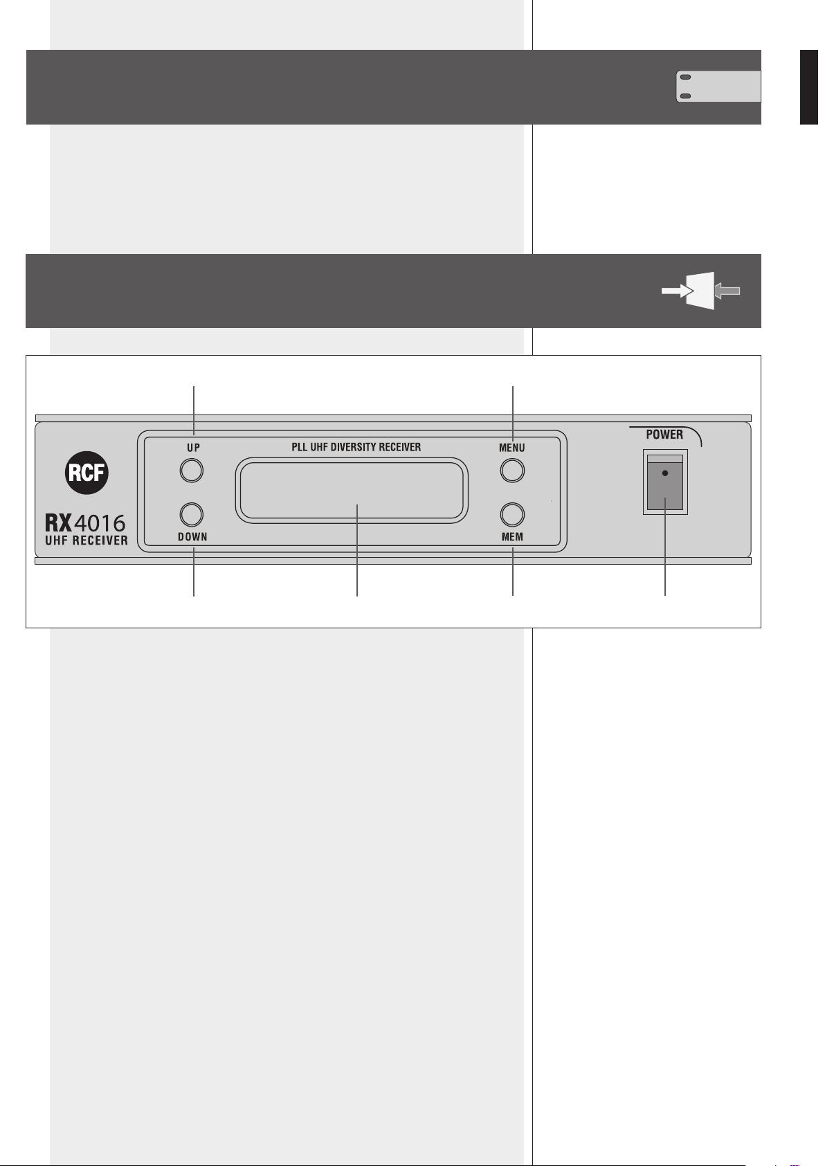
RX 4016 FRONT PANEL
1 POWER switch to turn the RX 4016 receiver on/off.
2 UP key: it increases the value of the selected parameter
(chosen through the MENU key 4).
3 DOWN key: it decreases the value of the selected parameter
(chosen through the MENU key 4).
4 MENU key: press once or more times to select the parameter to edit.
5 MEM key
- Press once (and immediately release) to store the new settings (when editing).
- Press and hold (1 second) to start the auto-scan.
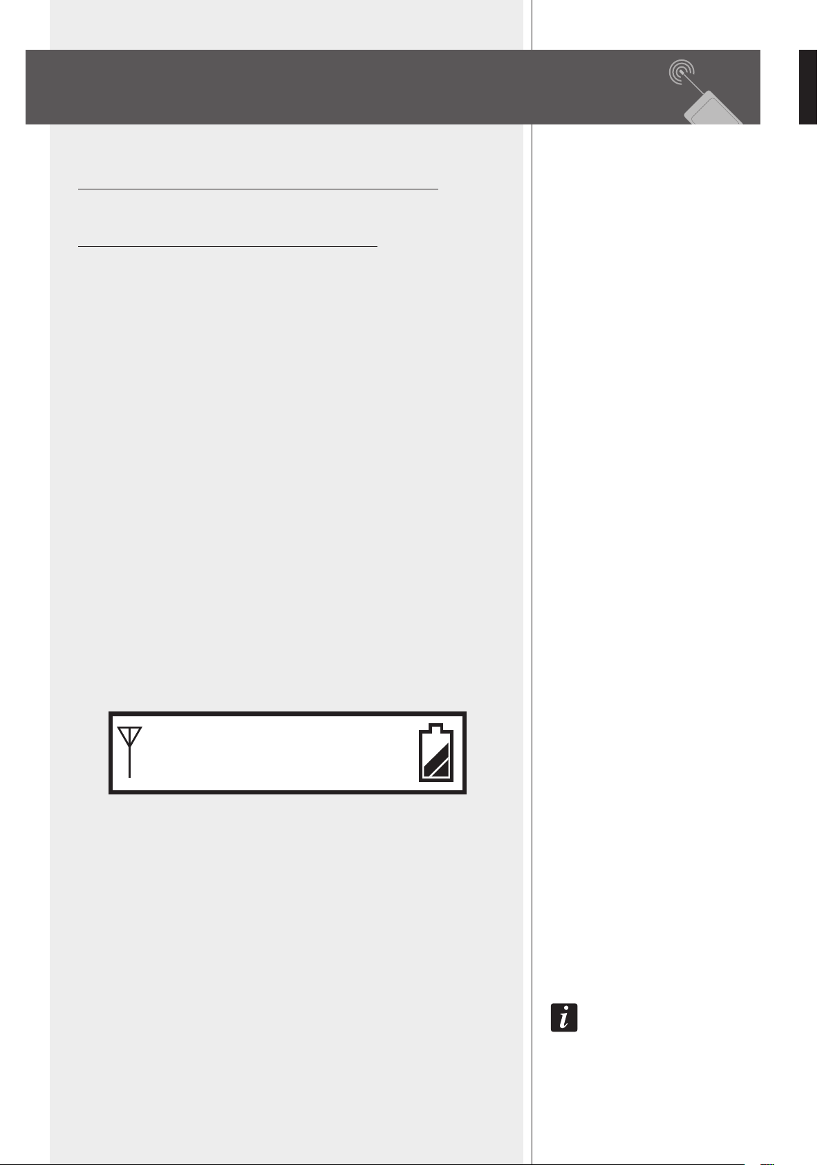
6 LCD Display
The LCD display shows both radio (RF) and audio (AF) signals, remaining battery life of
the transmitter, selected group – channel – frequency.
See the ‘RX 4016 operation’ manual section for detailed information.
4
5
2
3 6
1
8
ENGLISH
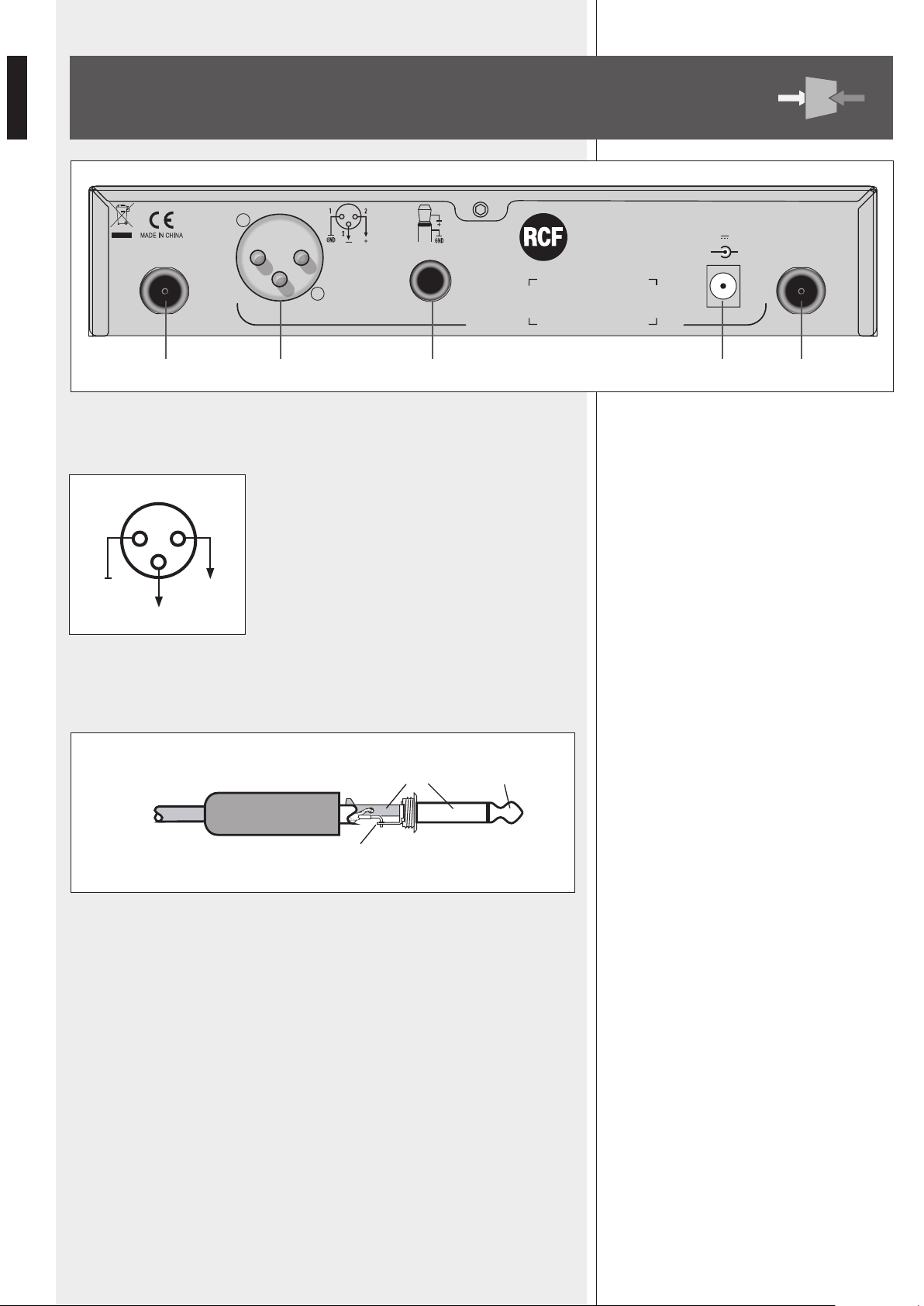
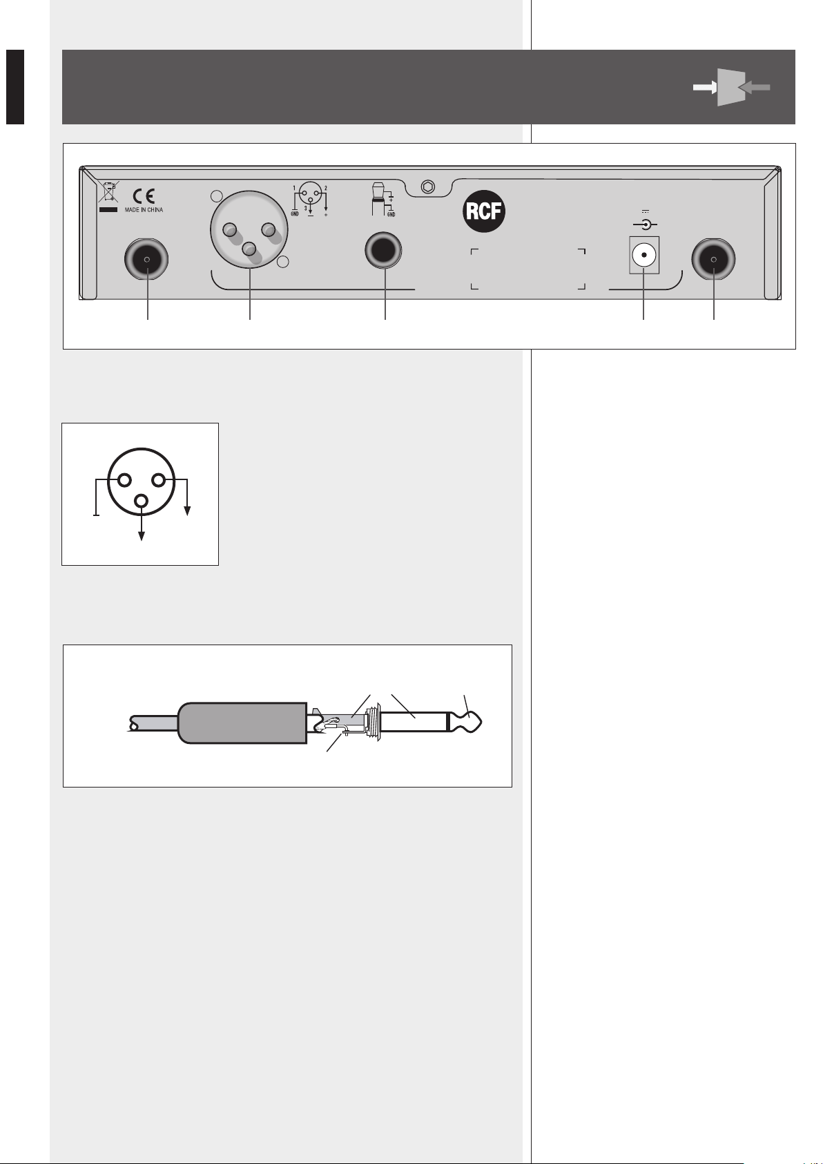
7 BALANCED AUDIO OUTPUT
XLR connector:
1 – ground
2 – audio signal (hot, +)
3 – audio signal (cold, –)
8 UNBALANCED AUDIO OUTPUT
6.3 mm (¼”) ‘TS’ jack connector:
9 POWER SUPPLY INPUT
Connect the output of the included power supply unit (15 V dc) to this input.
0 ANT-A, ANT-B antenna inputs
Inputs for the included antennas (or remote antennas, not included).
RX 4016 REAR PANEL
1 2
+
–
GND
3
UNBALANCED SIGNAL (TS JACK)
sleeve (gnd) tip
tip
= signal
UHF RECEIVER
+
AUDIO OUTPUT
BALANCED
Power Supply Input
12-18 V 300 mA
-
UN-BALANCED
POWER
Serial N°:
ANT-B ANT-A
RX4016
7 8 9
P P
9
ENGLISH
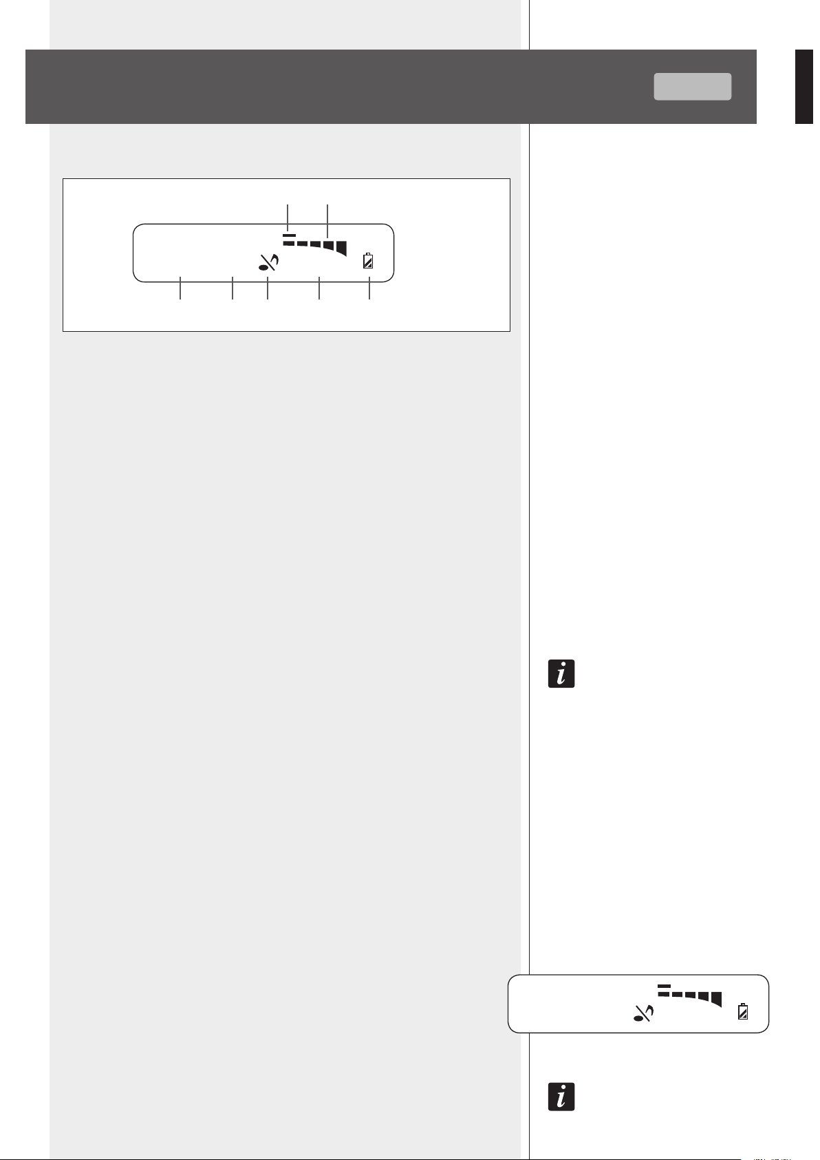
RX 4016 OPERATION
1 Selected frequency group (1 ÷ 10)
2 Selected channel (1 ÷ 12)
3 Mute function
4 Frequency (MHz) corresponding to the selected channel
5 Transmitter remaining battery life
6 AF: bar graph indicating the received audio level
7 RF: bar graph indicating the field strength of the received radio signal
AUTO-SCAN
Press and hold the MEM 5 key for one second to start the auto-scan function, which
automatically searches the current transmitter carrier frequency in the entire band.
During the search, the display shows the channel sequence and the audio output
is muted. As soon as the transmitter frequency is found, the scan will be stopped
automatically and the current channel / frequency will be flashing. At this point, press the
MEM key to store the new channel.
Note: in some cases, it may be necessary to select the channel manually
(see the next ‘manual channel selection’).
MANUAL CHANNEL SELECTION
Press the MENU 4 key: on display ‘GROUP’ is now flashing and it is possible to
select the group through the UP 2 / DOWN 3 keys.
When the group is set, press the MEM 5 key to store the new setting (or the MENU
4 key to cancel).
Then press the MENU 4 key twice (sequentially): on display ‘CHANNEL’ is now
flashing and it is possible to select the channel through the UP 2 / DOWN 3 keys.
When the channel is set, press the MEM 5 key to store the new setting (or the
MENU 4 key to cancel).
AUDIO OUTPUT LEVEL ADJUSTING (balanced audio output 7 only)
Press the MENU 4 key 3 times (sequentially): the display indicates ‘PL’ and a value.
Use the UP 2 / DOWN 3 keys to adjust the receiver (max.) audio output level:
- PL 0 500 mV
- PL 1 300 mV
- PL 2 150 mV
Press the MEM 5 key to store the new setting (or the MENU 4 key to cancel).
Note: this parameter only affects the balanced audio output 7.
DISPLAY
DISPLAY
AUTO-SCAN
MANUAL CHANNEL
SELECTION
AUDIO OUTPUT LEVEL
ADJUSTING
9 10
PL 1
661.325 MHz
AF
RF
10 9
661.325 MHz
7
42 31
6
5
GROUP CHANNEL
AF
RF
10
ENGLISH
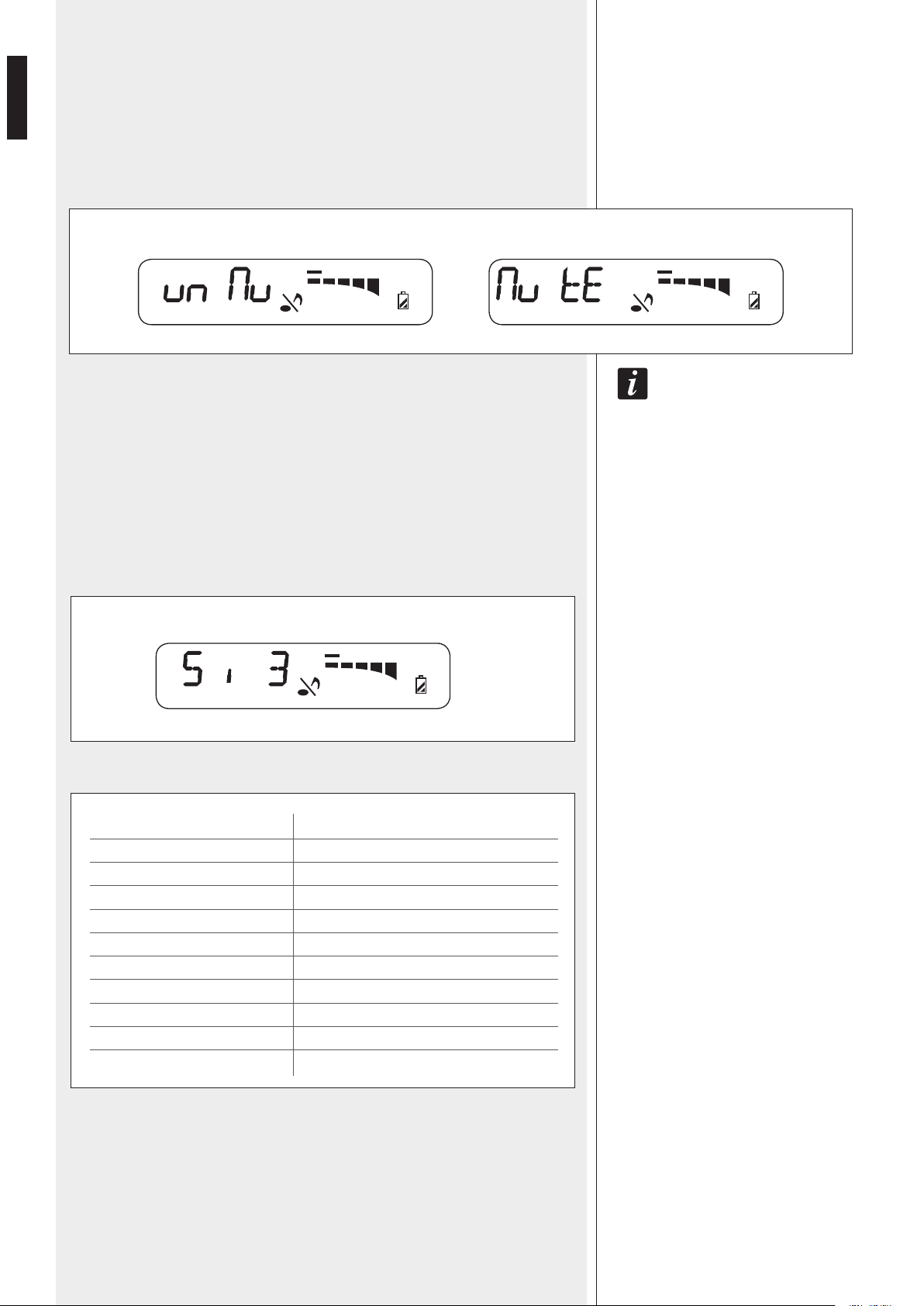
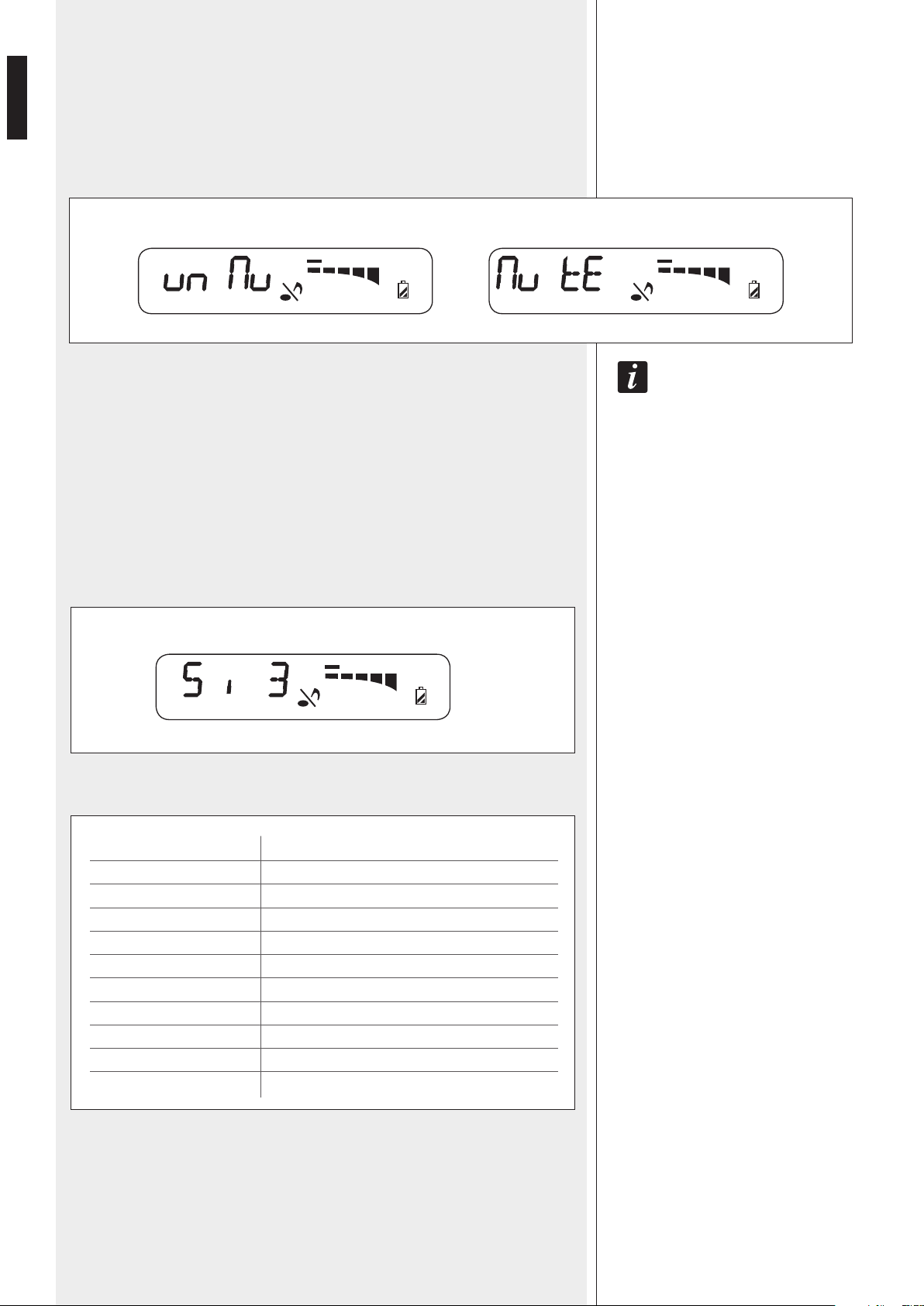
MUTE FUNCTION
Press the MENU 4 key 4 times (sequentially): the display indicates the mute function
(the note in the centre is now flashing).
Use the UP 2 / DOWN 3 keys to turn the mute function on / off and then press the
MEM 5 key to store the new setting (or the MENU 4 key to cancel).
If the mute function is on, the receiver audio output will be disabled.
Note: if the transmitter is muted, no audio signal will be sent out from the receiver!
SQUELCH CONTROL
The squelch can be useful to reduce audible noise during pauses, by muting the receiver
every time the radio signal level drops below a defined threshold, which is set through
the squelch control.
A higher value means a higher squelch threshold.
Use the squelch control with care: if its threshold is too high, the squelch could also mute
the transmitter signal. A too high squelch threshold also decreases the usable range.
Press the MENU 4 key 5 times (sequentially): the display indicates 'Si' and a value.
Use the UP 2 / DOWN 3 keys to adjust the receiver squelch threshold:
Press the MEM
5 key to store the new setting (or the MENU 4 key to cancel).
VALUE
1
2
3
4
5
6
7
8
9
10
SQUELCH THRESHOLD LEVEL
- 95.0 dB
- 91.7 dB
- 88.3 dB
- 85.0 dB
- 81.7 dB
- 78.3 dB
- 75.0 dB
- 71.7 dB
- 68.3 dB
- 65.0 dB
SQUELCH CONTROL
MUTE FUNCTION
661.325 MHz
AF
RF
661.325 MHz
AF
RF
MUTE FUNCTION: OFF MUTE FUNCTION: ON
661.325 MHz
AF
RF

11
ENGLISH
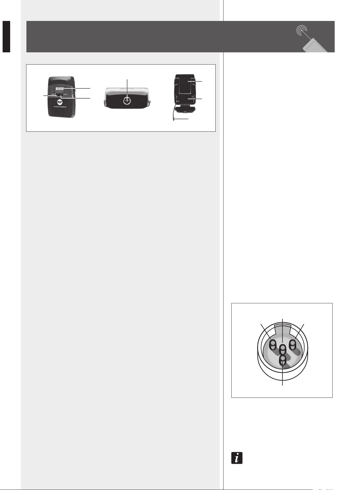
Remove (unscrew) the microphone handle to access the battery compartment 5.
1 MIC. CAPSULE GRILLE
Extremely rugged spring steel mesh grille to protect the capsule underneath in live
performances.
2 LCD DISPLAY
See the ‘TX 4000 / PX 4100 transmitter operation’ manual section for detailed
information.
3 CH/ON key
Press and hold (for a few seconds) this key to turn the transmitter on / off.
When the transmitter is switched on, press once or more times to select the parameter to
edit:
- C H. channel selection
- G P. group selection
- P L. RF power level
- Unlock / Lock
Press once or more time the SELECT key 4 to change values.
After a few seconds since the last setting, the display will show the current selected
frequency [MHz] and the battery life.
4 SELECT key
Press once or more time to change values when editing parameters.
Press and hold (for a few seconds) to mute / unmute the microphone.
5 BATTERY COMPARTMENT
Use 2 non-rechargeable ‘AA’ type (1.5 V) batteries, better if alkaline and new.
Pay attention to the polarity when inserting the 2 batteries.
6 ANTENNA
The antenna is integrated in the transmitter, under the coloured plastic cap (that is
available in 7 different colours for easy identification).
TX 4000 TRANSMITTER / HANDHELD
DYNAMIC MICROPHONE
124
3
56
12
ENGLISH
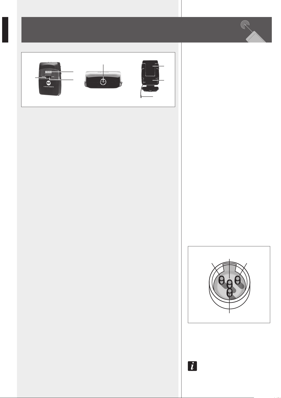
1 LCD DISPLAY
See the 'TX 4000 / PX 4100 transmitter operation' manual section for detailed
information.
2 CH/ON key
Press and hold (for a few seconds) this key to turn the transmitter on / off.
When the transmitter is switched on, press once or more times to select the parameter to
edit:
- C H. channel selection
- G P. group selection
- P L. RF power level
- Unlock / Lock
Press once or more time the SELECT key 3 to change values.
After a few seconds since the last setting, the display will show the current selected
frequency [MHz] and the battery life.
3 SELECT key
Press once or more time to change values when editing parameters.
Press and hold (for a few seconds) to mute / unmute the transmitter.
4 INPUT (mini 4P connector)
Input for the LA 2004 'Lavalier' (tie-clip) electret microphone.
PIN
1. ground
2. power supply for electret microphones
3. audio signal input for an electric guitar / bass
(a cable with jack - mini 4p connectors is needed, NOT included in RCF kits)
4. audio signal input for a microphone
5 BATTERY COMPARTMENT
Use 2 non-rechargeable ‘AA’ type (1.5 V) batteries, better if alkaline and new.
Pay attention to the polarity when inserting the 2 batteries.
6 BELT CLIP
7 FLEXIBLE ANTENNA
note: avoid covering the antenna with hands, clothes, etc.
1
4
3
2
PIN
PX 4100 BODY PACK TRANSMITTER
4
1
7
2
3
5
6
13
ENGLISH
TX 4000 / PX 4100
TRANSMITTER OPERATION
IMPORTANT INFORMATION
- Refer to local regulations for the use of wireless microphones.
- When more wireless devices are used at the same time, each transmitter / receiver
pair shall be set to its own channel that must be different from all already used.
A channel (frequency) can be used for 1 transmitter only (2 or more transmitters
cannot be set to the same channel).
- It is possible to use up to 16 channels simultaneously.
For instance, the following 10 channels can be used simultaneously without any
interference:
- group 1, channel 1 638.125 MHz
- group 1, channel 2 638.325 MHz
- group 1, channel 5 638.925 MHz
- group 2, channel 2 640.725 MHz
- group 2, channel 10 642.325 MHz
- group 4, channel 3 645.725 MHz
- group 5, channel 2 647.925 MHz
- group 6, channel 8 651.525 MHz
- group 7, channel 1 652.525 MHz
- group 8, channel 5 655.725 MHz
- In case of interferences due to lighting equipments, computers, other radio transmitters,
etc. nearby, it is advisable to try different frequencies.
- Wireless microphones should be used in an open-space with no obstacles (especially
metallic objects) between transmitters and receivers.
- For the best performances, always use 2 new non-rechargeable alkaline ‘AA’ TYPE
batteries and keep transmitters as close as possible to receivers.
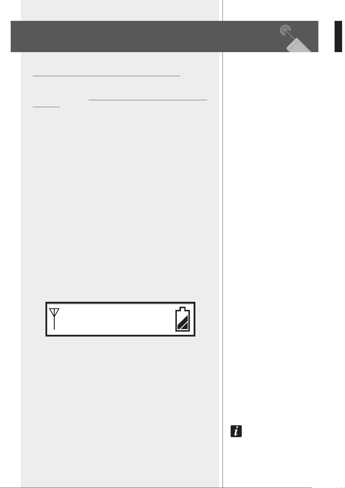
Press and hold (for a few seconds) the CH/ON key
2 to turn the transmitter on.
The current selected frequency [MHz] and the battery life are displayed.
OPERATION
When the transmitter is switched on, press once or more times the CH/ON key 2 to
select the parameter to edit:
- C H. channel selection
- G P. group selection
- P L. RF power level
- Unlock / Lock (setting protection)
Press once or more time the SELECT key 3 to change values.
the select key 3 cannot change channels, groups and rf power if the ‘unlock / lock’
parameter is set to ‘lock’.
After a few seconds since the last setting, the display will show the current selected
frequency and the battery life again.
IMPORTANT INFORMATION
OPERATION
638. 125
MHz

14
ENGLISH
CHANNEL SELECTION
The frequency range is in the UHF band (638 ÷ 662 MHz).
Before setting a different channel, please see the table (groups, channels and respective
frequencies) in the 'Frequency' manual section.
For instance, to select the frequency preset of 659.125 MHz (group 9, channel 10), please
follow the following procedure:
- Turn the transmitter on first.
- Press CH/ON key 2 once to edit the channel parameter, then press once or more times
the SELECT key 3 to specify the proper channel (example: no. 10).
- Press the CH/ON key 2 once again to edit the group parameter, then press once or
more times the SELECT key 3 to specify the proper group (example: no. 9).
After a few seconds, the last setting will be automatically stored and the display will
show the (new) selected frequency and the battery life again.
RF OUTPUT POWER SELECTION
Press CH/ON key 2 3 times to edit the RF output power, then press once or more time
the SELECT key 3 to change values.
SELECTION
PL 0
PL 1
PL 2
TX 4000 / PX 4100 RF OUTPUT POWER
1 mW
3 mW
10 mW
After a few seconds, the last setting will be automatically stored and the display will
show the selected frequency and the battery life again.
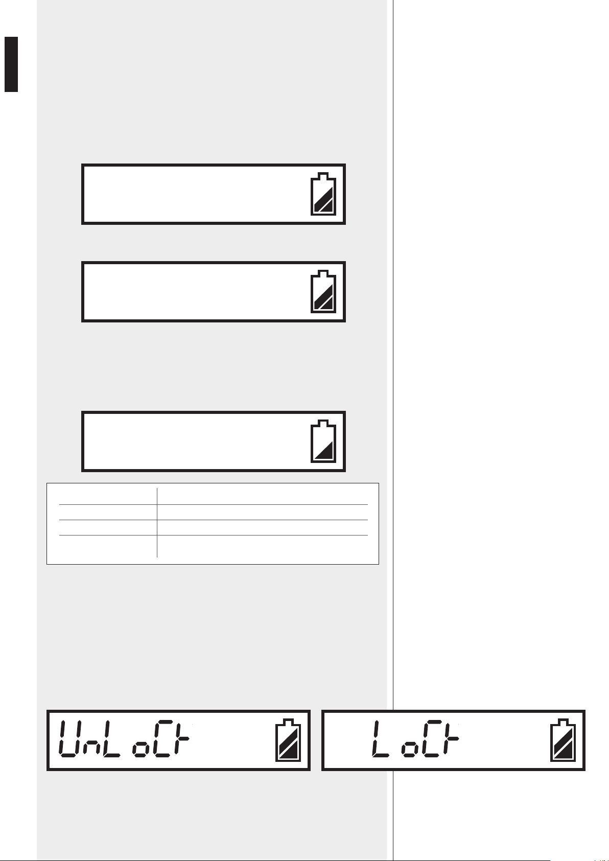
LOCK FUNCTION
Since the CH/ON and SELECT keys may be accidentally pressed, it is possible to protect
the current settings thanks to the 'lock' function.
When the transmitter is set to 'lock', it is still possible to use the CH/ON key to select
parameters, but only the 'Unlock / Lock' can be edited.
Press CH/ON key 2 4 times to edit the 'Unlock / Lock' parameter, then use the SELECT
key 3 to select.
After a few seconds, the last setting will be automatically stored and the display will
show the selected frequency and the battery life again.
CHANNEL SELECTION
C H. 10
G P. 9
P L. 2
LOCK FUNCTION
15
ENGLISH
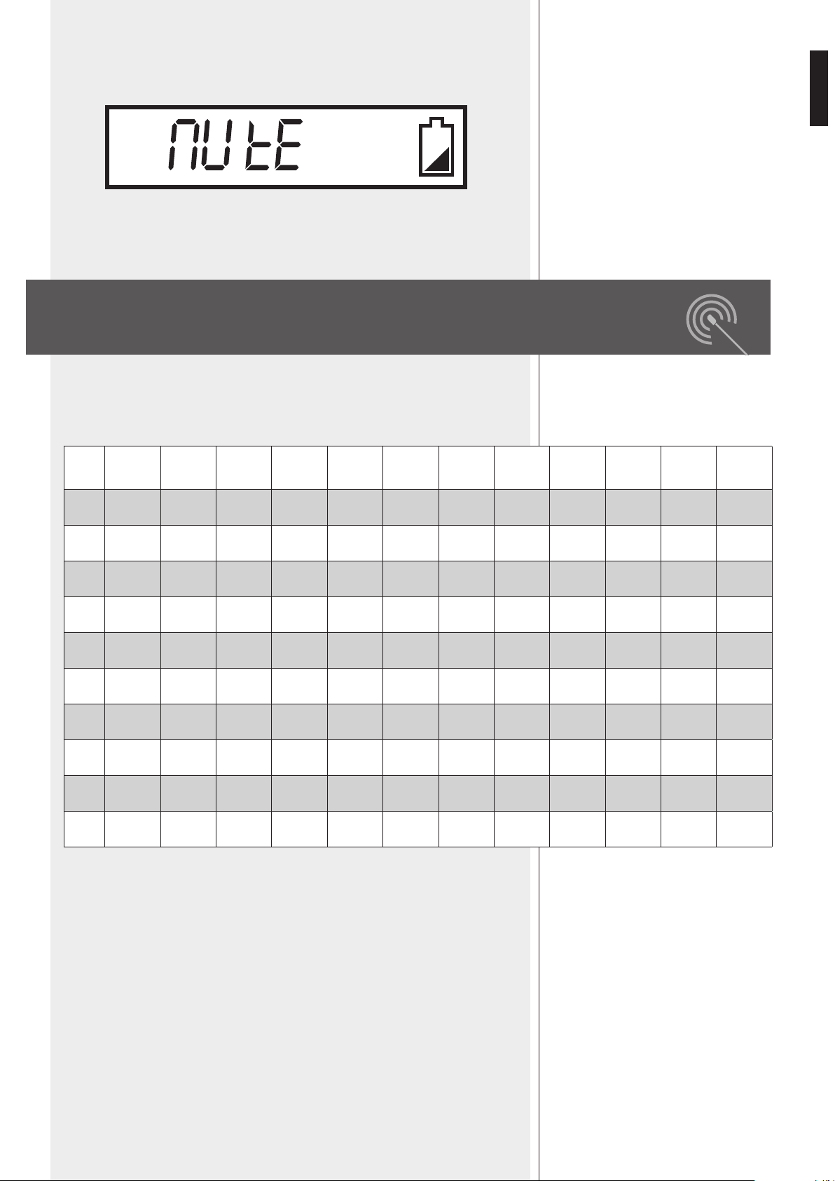
MUTE
Press and hold (for a few seconds) the SELECT key 3 to mute the transmitter.
When the transmitter is muted, the audio signal is NOT transmitted (while the carrier
radio signal is still present).
Press and hold the SELECT key 3 again to unmute the transmitter.
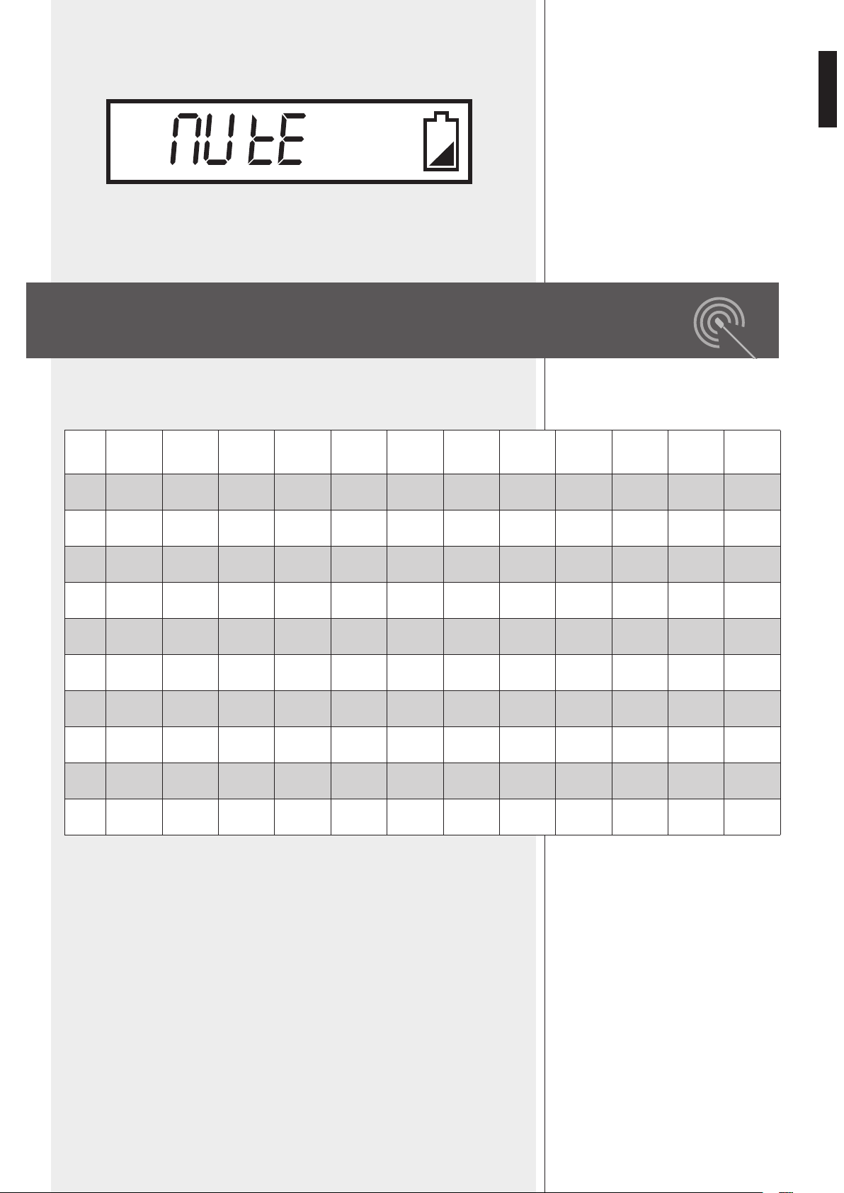
The following table shows all available frequencies [MHz] assigned to every
group / channel.
FREQUENCIES
MUTE
Channel
1
Channel
2
Channel
3
Channel
4
Channel
5
Channel
6
Channel
7
Channel
8
Channel
9
Channel
10
Channel
11
Channel
12
Gr. 1
638.125 638.325 638.525 638.725 638.925 639.125 639.325 639.525 639.725 639.925 640.125 640.325
Gr. 2
640.525 640.725 640.925 641.125 641.325 641.525 641.725 641.925 642.125 642.325 642.525 642.725
Gr. 3
642.925 643.125 643.325 643.525 643.725 643.925 644.125 644.325 644.525 644.725 644.925 645.125
Gr. 4
645.325 645.525 645.725 645.925 646.125 646.325 646.525 646.725 646.925 647.125 647.325 647.525
Gr. 5
647.725 647.925 648.125 648.325 648.525 648.725 648.925 649.125 649.325 649.525 649.725 649.925
Gr. 6
650.125 650.325 650.525 650.725 650.925 651.125 651.325 651.525 651.725 651.925 652.125 652.325
Gr. 7
652.525 652.725 652.925 653.125 653.325 653.525 653.725 653.925 654.125 654.325 654.525 654.725
Gr. 8
654.925 655.125 655.325 655.525 655.725 655.925 656.125 656.325 656.525 656.725 656.925 657.125
Gr. 9
657.325 657.525 657.725 657.925 658.125 658.325 658.525 658.725 658.925 659.125 659.325 659.525
Gr.10
659.725 659.925 660.125 660.325 660.525 660.725 660.925 661.125 661.325 661.525 661.725 661.925

16
ENGLISH
SYSTEM
Channel
Type
Frequency band
Frequency response
Frequency stability
T.H.D.
Modulation mode
Dynamic
RX 4016 RECEIVER
Balanced audio output
Unbalanced audio output
S/N Ratio
RF sensitivity
Power supply
Dimensions
Net weight
TX 4000 TRANSMITTER / HANDHELD MICROPHONE
RF output power
Frequency response
Microphone capsule
Tone frequency
Max. deviation
Batteries
Dimensions
Net weight
PX 4100 BODY PACK TRANSMITTER
RF output power
Frequency response
LA 2004 mic. freq. resp.
Tone frequency
Max. deviation
Batteries
Dimensions
Net weight
Included microphone
single (out of 120 frequencies)
(PLL) UHF, ‘diversity’ receiver
UHF, 638 ÷ 662 MHz
50 Hz ÷ 50 kHz (± 3 dB)
± 0.005 % (–10 ÷ 50°C)
< 0.8% (1 kHz)
FM (F3E)
> 100 dB
1 V, ± 35 kHz deviation
750 mV, ± 35 kHz deviation
> 90 dB
– 100 dBm / 30 dB SINAD
through external 15 V dc (0.5A) adapter
210 mm (w), 44 mm (h), 155 mm (d);
(8.2” x 1.7” x 6.1”)
0.99 kg
1 - 3 - 10 mW
90 Hz ÷ 12 kHz (± 3 dB)
dynamic, cardioid
30-33 kHz
± 35 kHz
2 x ‘AA’ type (1.5 V, non rechargeable)
277 mm (l), Ø 36.5 mm;
(10.9” x Ø 1.44”)
0.25 kg
1 - 3 - 10 mW
50 Hz ÷ 15 kHz (± 3 dB)
100 Hz ÷ 12 kHz (± 3 dB)
30-33 kHz
± 35 kHz
2 x ‘AA’ type (1.5 V, non rechargeable)
97 mm (w), 68 mm (h), 22 mm (d);
(3.82” x 2.68” x 0.87”)
0.09 kg
LA 2004 ‘Lavalier’ (tie-clip) electret
microphone
SPECIFICATIONS


18
ITALIANO
IMPORTANTE
Prima di collegare ed utilizzare questo prodotto, leggere attentamente le istruzioni
contenute in questo manuale, il quale è da conservare per riferimenti futuri.
Il presente manuale costituisce parte integrante del prodotto e deve accompagnare
quest’ultimo anche nei passaggi di proprietà, per permettere al nuovo proprietario di
conoscere le modalità d’installazione e d’utilizzo e le avvertenze per la sicurezza.
L’installazione e l’utilizzo errati del prodotto esimono la RCF S.p.A. da ogni responsabilità.
ATTENZIONE: Per prevenire i rischi di fiamme o scosse elettriche, non esporre mai
questo prodotto alla pioggia o all’umidità.
AVVERTENZE PER LA SICUREZZA
1. Tutte le avvertenze, in particolare quelle relative alla sicurezza, devono essere lette con
particolare attenzione, in quanto contengono importanti informazioni.
2. Alimentare il ricevitore utilizzando solo l’alimentatore dedicato; verificare che la
tensione della vostra rete corrisponda quella di targa dell’alimentatore e che il valore
ed il tipo (continua o alternata) di tensione d’uscita dello stesso corrisponda a quella
d’ingresso del ricevitore, in caso contrario rivolgersi ad un rivenditore RCF; verificare
inoltre che l’alimentatore non sia stato danneggiato da eventuali urti o sovraccarichi.
La tensione di rete, alla quale è connesso l’alimentatore, ha un valore sufficientemente
alto da costituire un rischio di folgorazione per le persone: prestare attenzione durante
la connessione alla rete (es. non effettuarla con le mani bagnate) e non aprire mai
l’alimentatore. Accertarsi che il cavo dell’alimentatore non sia o possa essere schiacciato
da altri oggetti (prestando particolare attenzione alla parte del cavo vicino alla spina ed
al punto dove questo esce dall’alimentatore).
3. Impedire che oggetti o liquidi entrino all’interno dei prodotti, perché potrebbero
causare un corto circuito. Tutti gli apparecchi non devono essere esposti a stillicidio o a
spruzzi d’acqua; nessun oggetto pieno di liquido (es. vasi) e nessuna sorgente di fiamma
nuda (es. candele accese) deve essere posto sugli apparecchi.
4. Non eseguire sui prodotti interventi / modifiche / riparazioni se non quelle
espressamente descritte sul manuale istruzioni.
Contattare centri di assistenza autorizzati o personale altamente qualificato quando:
- l’apparecchio non funziona (o funziona in modo anomalo);
- l’alimentatore e/o il suo cavo sono danneggiati;
- oggetti o liquidi sono entrati nell’apparecchio;
- l’apparecchio ha subito forti urti.
5. Qualora questo prodotto non sia utilizzato per lunghi periodi, scollegare l’alimentatore
del ricevitore dalla rete elettrica e rimuovere le batterie dal trasmettitore.
6. Nel caso che da un prodotto provengano odori anomali o fumo, spegnerlo
immediatamente, scollegare l’alimentatore del ricevitore dalla rete elettrica e/o rimuovere
le batterie dal trasmettitore.
7. Non collegare a questo prodotto altri apparecchi e accessori non previsti.
Verificare l’idoneità della superficie sulla quale il ricevitore è posizionato, considerando,
ad esempio, vibrazioni meccaniche normalmente generate da un trasduttore.
Per evitare il pericolo di cadute, non sovrapporre fra loro più ricevitori.
8. La RCF S.p.A. raccomanda vivamente che l’installazione di questo prodotto sia
eseguita solamente da installatori professionali qualificati (oppure da ditte specializzate)
in grado di farla correttamente e certificarla in accordo con le normative vigenti. Tutto
IMPORTANTE
ATTENZIONE
AVVERTENZE PER LA SICUREZZA

19
ITALIANO
il sistema audio dovrà essere in conformità con le norme e le leggi vigenti in materia di
impianti elettrici.
9. Sostegni e Carrelli
Se previsto, il prodotto va utilizzato solo su carrelli o sostegni consigliati dal produttore.
L’insieme apparecchio-sostegno / carrello va mosso con estrema cura. Arresti improvvisi,
spinte eccessive e superfici irregolari o inclinate possono provocare il ribaltamento
dell’assieme.
10. Vi sono numerosi fattori meccanici ed elettrici da considerare quando si installa un
sistema audio professionale (oltre a quelli prettamente acustici, come la pressione sonora,
gli angoli di copertura, la risposta in frequenza, ecc.).
11. Perdita dell’udito
L’esposizione ad elevati livelli sonori può provocare la perdita permanente dell’udito.
Il livello di pressione acustica pericolosa per l’udito varia sensibilmente da persona
a persona e dipende dalla durata dell’esposizione. Per evitare un’esposizione
potenzialmente pericolosa ad elevati livelli di pressione acustica, è necessario che
chiunque sia sottoposto a tali livelli utilizzi delle adeguate protezioni; quando si fa
funzionare un trasduttore in grado di produrre elevati livelli sonori è necessario indossare
dei tappi per orecchie o delle cuffie protettive.
Consultare i dati tecnici contenuti nei manuali istruzioni per conoscere le massime
pressioni sonore che i diffusori acustici sono in grado di produrre.
12. Per evitare fenomeni di rumorosità indotta sui cavi che trasportano segnali dai
microfoni o di linea (per esempio 0dB), usare solo cavi schermati ed evitare di posarli
nelle vicinanze di:
- apparecchiature che producono campi elettromagnetici di forte intensità;
- cavi della rete elettrica;
- linee che alimentano altoparlanti.
13. Non puntare microfoni verso altoparlanti vicini (in modo da evitare fischi fastidiosi).
14. Collocare il prodotto lontano da fonti di calore e garantire la circolazione dell’aria
intorno.
15. Non forzare mai gli organi di comando (tasti, manopole ecc.).
16. Non usare solventi, alcool, benzina o altre sostanze volatili per la pulitura delle parti
esterne; usare un panno asciutto.
INFORMAZIONI SULLE PILE
1. Usare pile tipo AA (1,5 V) non ricaricabili, meglio se alcaline e possibilmente nuove.
2. Non utilizzare contemporaneamente pile vecchie e nuove.
3. Non utilizzare contemporaneamente tipi diversi di pile.
4. Non tentare di ricaricare pile non ricaricabili.
5. Verificare che sia rispettata la polarità delle pile, seguendo le indicazioni riportate sul
vano del trasmettitore.
6. Togliere le pile una volta esaurite o nel caso il radiomicrofono non sia utilizzato per un
lungo periodo.
7. Non cortocircuitare le pile (ad esempio collegando i 2 poli opposti con un filo di
metallo).
8. Smaltire le pile esaurite negli appositi contenitori, facendo riferimento alle norme di
legge vigenti (nel paese di utilizzo) in materia di ecologia e protezione dell’ambiente.
9. Non gettare mai le pile nel fuoco od immergerle nell’acqua.
INFORMAZIONI SULLE PILE

20
ITALIANO
RCF S.P.A. VI RINGRAZIA PER L’ACQUISTO DI QUESTO PRODOTTO, REALIZZATO
IN MODO DA GARANTIRNE L’AFFIDABILITÀ E PRESTAZIONI ELEVATE.
DESCRIZIONE
TX 4016 e PX 4116 sono radiomicrofoni UHF.
Ciascun ricevitore ha 2 antenne in modo da ottenere la funzione “diversity”
(è automaticamente selezionato il segnale radio con livello più alto ricevuto da una
delle 2 antenne), che comporta una migliore affidabilità e copertura con meno rischi di
interruzioni ed interferenze.
La frequenza portante del trasmettitore può essere ricercata automaticamente grazie alla
funzione “auto-scan” del ricevitore.
È ovviamente possibile scegliere manualmente il canale sia nel trasmettitore sia nel
ricevitore.
Sono disponibili 120 canali (10 gruppi, ciascuno con 12 frequenze diverse).
È possibile utilizzare fino a 16 canali contemporaneamente (avendo a disposizione
16 radiomicrofoni).
Il kit TX 4016 include:
- un ricevitore RX 4016
(con alimentatore AC / DC, 2 antenne ed un cavo da 1,5 m con jack 6,3 mm);
- un trasmettitore ad impugnatura TX 4000 con microfono dinamico.
Il kit PX 4116 include:
- un ricevitore RX 4016
(con alimentatore AC / DC, 2 antenne ed un cavo da 1,5 m con jack 6,3 mm);
- un trasmettitore per cintura PX 4100;
- un microfono ad elettrete di tipo “Lavalier” LA 2004.
CARATTERISTICHE PRINCIPALI
COMUNI
- PLL (“phase-locked loop”: anello ad aggancio di fase), banda UHF.
- Utilizzo simultaneo di max. 16 canali / frequenze (su 120 disponibili).
RICEVITORE RX 4016 CON FUNZIONE “DIVERSITY”
- Interfaccia utente semplice con display LCD frontale.
- Ricerca automatica della frequenza portante del trasmettitore.
- Commutazione automatica dell’antenna ricevente il segnale radio (funzione “diversity”).
- Selezione di 3 livelli d’uscita.
- Controllo “Squelch”.
TRASMETTITORI TX 4000 / PX 4100
- Verniciatura “Soft touch” per un uso più confortevole.
- Selezione di 3 livelli di potenza del segnale radio in uscita.
- Disattivazione del microfono (funzione “Mute”).
- Protezione delle impostazioni da modifiche accidentali (funzione “Lock”).
CARATTERISTICHE
PRINCIPALI

21
ITALIANO
Ciascun ricevitore RX 4016 può normalmente essere posizionato su di un banco (o su un
tavolo, sopra un rack, ecc.).
Il kit opzionale RCF AR 1620 permette di installare uno od una coppia di ricevitori RX
4016 in un rack 19” (spazio: 1 unità).
INSTALLAZIONE A RACK (19”)
DEI RICEVITORI RX 4016
RX 4016 – PANNELLO FRONTALE
1 POWER: interruttore per accendere (ON) o spegnere (OFF) il ricevitore.
2 Tasto UP: incrementa il valore del parametro selezionato
(scelto tramite il tasto MENU 4).
3 Tasto DOWN: diminuisce il valore del parametro selezionato
(scelto tramite il tasto MENU 4).
4 Tasto MENU: premere una o più volte per selezionare il parametro da modificare.
5 Tasto MEM:
- premere una volta (e rilasciare immediatamente) per memorizzare le nuove impostazioni
(durante le modifiche dei parametri);
- premere e tener premuto (per almeno 1 secondo) per avviare la ricerca automatica della
frequenza.
6 Display LCD
Il display LCD mostra sia il segnale radio (RF) sia quello audio (AF), la carica rimanente
delle pile ed il gruppo – canale (– frequenza) selezionato.
Vedere la sezione del manuale “Funzionamento del ricevitore RX 4016” per ulteriori
informazioni.
4
5
2
3 6
1
22
ITALIANO
SEGNALE SBILANCIATO (JACK “TS”)
manica = massa punta
punta
= segnale
7 BALANCED AUDIO OUTPUT
Uscita audio bilanciata con connettore XLR:
1 – massa
2 – segnale audio (+)
3 – segnale audio (–)
8 UNBALANCED AUDIO OUTPUT
Uscita audio sbilanciata con presa per jack 6,3 mm “TS”:
9 POWER SUPPLY INPUT
Ingresso per l’alimentatore fornito a corredo (15 V dc).
0 ANT-A, ANT-B ingressi per le antenne
Ingressi per le antenne incluse (od antenne remote, non incluse).
RX 4016 - PANNELLO POSTERIORE
UHF RECEIVER
+
AUDIO OUTPUT
BALANCED
Power Supply Input
12-18 V 300 mA
-
UN-BALANCED
POWER
Serial N°:
ANT-B ANT-A
RX4016
7 8 9
P P
1 2
+
–
GND
3

23
ITALIANO
FUNZIONAMENTO DEL RICEVITORE RX 4016
1 Gruppo selezionato (1 ÷ 10)
2 Canale selezionato (1 ÷ 12)
3 Funzione “Mute” inserita
4 Frequenza (MHz) corrispondente al canale selezionato
5 Stato di carica delle pile
6 AF: barra indicante il livello del segnale audio ricevuto
7 RF: barra indicante l’intensità di campo del segnale radio ricevuto
RICERCA AUTOMATICA DELLA FREQUENZA PORTANTE
Premere e tener premuto il tasto MEM 5 (per almeno un secondo) per avviare la ricerca
automatica della frequenza portante (nell’intera banda) del trasmettitore.
Durante la ricerca, il display mostra i canali in sequenza e l’uscita audio è disattivata. Non
appena la frequenza del trasmettitore è stata trovata, la ricerca si ferma automaticamente
ed il canale / la frequenza corrente lampeggia. A questo punto, premere il tasto MEM per
memorizzare il nuovo canale.
Nota: in alcuni casi, potrebbe essere necessario selezionare il canale manualmente (vedere il
paragrafo successivo “selezione manuale del canale”).
SELEZIONE MANUALE DEL CANALE
Premere il tasto MENU 4: l’indicazione GROUP sul display ora lampeggia ed è possibile
selezionare il gruppo tramite i tasti UP 2 e DOWN 3.
Non appena il gruppo è stato impostato, premere il tasto MEM 5 per memorizzarlo (od
il tasto MENU 4 per cancellare la modifica).
Successivamente premere il tasto MENU 4 due volte (in sequenza): l’indicazione
CHANNEL sul display ora lampeggia ed è possibile selezionare il canale tramite i tasti UP
2 e DOWN 3.
Quando anche il canale è stato impostato, premere il tasto MEM 5 per memorizzarlo
(od il tasto MENU 4 per cancellare la modifica).
IMPOSTAZIONE DEL LIVELLO AUDIO D’USCITA
(SOLO PER L’USCITA AUDIO BILANCIATA 7)
Premere il tasto MENU 4 tre volte (in sequenza): il display mostra l’indicazione PL ed un
valore.
Impostare il livello (max.) d’uscita audio del ricevitore tramite i tasti UP 2 e DOWN 3:
- PL 0 500 mV
- PL 1 300 mV
- PL 2 150 mV
Premere il tasto MEM
5 per memorizzarlo (od il tasto MENU 4 per cancellare
la modifica).
Nota: questo parametro agisce solo sull’uscita audio bilanciata 7.
DISPLAY
DISPLAY
RICERCA AUTOMATICA
DELLA FREQUENZA PORTANTE
SELEZIONE MANUALE
DEL CANALE
IMPOSTAZIONE DEL LIVELLO
AUDIO D’USCITA
9 10
10 9
661.325 MHz
7
42 31
6
5
GROUP CHANNEL
AF
RF
PL 1
661.325 MHz
AF
RF
24
ITALIANO
FUNZIONE “MUTE” (disattivazione dell’uscita audio del ricevitore)
Premere il tasto MENU 4 quattro volte (in sequenza): il display mostra l’indicazione
della funzione “Mute” quando attivata: una nota lampeggiante al centro.
Usare i tasti UP 2 e DOWN 3 per attivare o disattivare la funzione “Mute” e,
successivamente, premere il tasto MEM 5 per memorizzare la nuova impostazione (od il
tasto MENU 4 per cancellare la modifica).
Quando la funzione “Mute” è selezionata, l’uscita audio del ricevitore è disattivata.
Nota: se la funzione “mute” è attivata, nessun segnale audio è presente all’uscita del ricevitore!
CONTROLLO “SQUELCH”
Lo “squelch” può essere utile per ridurre il rumore udibile durante le pause, disattivando
l’uscita audio del ricevitore ogni qualvolta il livello del segnale radio è sotto una certa
soglia, la quale è fissata tramite il controllo “squelch”. Usare il controllo “squelch” con
attenzione: se la soglia è troppo alta, lo “squelch” potrebbe bloccare anche il segnale del
trasmettitore.
Una soglia di “squelch” troppo alta diminuisce anche il campo d’azione del trasmettitore.
Premere il tasto MENU 4 cinque volte (in sequenza): il display mostra l’indicazione ‘Si’
ed un valore.
Usare i tasti UP 2 e DOWN 3 per impostare il livello della soglia di “squelch” del
ricevitore:
Premere il tasto MEM
5 per memorizzare la nuova impostazione (od il tasto MENU 4
per cancellare la modifica).
VALORE
1
2
3
4
5
6
7
8
9
10
LIVELLO DELLA SOGLIA DI “SQUELCH”
- 95.0 dB
- 91.7 dB
- 88.3 dB
- 85.0 dB
- 81.7 dB
- 78.3 dB
- 75.0 dB
- 71.7 dB
- 68.3 dB
- 65.0 dB
CONTROLLO “SQUELCH”
FUNZIONE “MUTE”
661.325 MHz
AF
RF
661.325 MHz
AF
RF
FUNZIONE MUTE DISATTIVATA FUNZIONE MUTE ATTIVATA
661.325 MHz
AF
RF

25
ITALIANO
Rimuovere (svitare) l’impugnatura del microfono per accedere al vano delle pile 5.
1 GRIGLIA DELLA CAPSULA MICROFONICA
Griglia in acciaio per la protezione della capsula microfonica durante l’uso.
2 DISPLAY LCD
Vedere la sezione del manuale “Funzionamento dei trasmettitori TX 4000 / PX 4100” per
le informazioni dettagliate.
3 Tasto CH/ON
Premere e tener premuto (per almeno un secondo) questo tasto per accendere o
spegnere il trasmettitore. Quando il trasmettitore è acceso, premere una o più volte per
selezionare il parametro da modificare:
- C H. selezione del canale
- G P. selezione del gruppo (di canali)
- P L. impostazione della potenza radio d’uscita
- Unlock / Lock protezione delle impostazioni
Premere una o più volte il tasto SELECT 4 per cambiare i valori.
Dopo pochi secondi dall’ultima modifica, il display mostrerà di nuovo la frequenza
selezionata corrente [MHz] e la carica delle pile.
4 Tasto SELECT
Premere una o più volte per cambiare i valori durante la modifica dei parametri.
Premere e tenere premuto (per qualche secondo) per disattivare momentaneamente
(funzione “mute”) il microfono (senza spegnere il trasmettitore).
5 VANO PER LE PILE
Usare 2 pile tipo AA (1,5 V) non ricaricabili, meglio se alcaline e possibilmente nuove.
Prestare attenzione alla polarità quando si inseriscono le 2 pile.
6 ANTENNA
L’antenna è integrata nel corpo del trasmettitore, sotto il tappo colorato di plastica (che è
disponibile in 7 colori diversi per rendere più semplice l’identificazione del microfono).
TRASMETTITORE AD IMPUGNATURA
TX 4000 CON MICROFONO DINAMICO
124
3
56
26
ITALIANO
1 DISPLAY LCD
Vedere la sezione del manuale “Funzionamento dei trasmettitori TX 4000 / PX 4100” per
le informazioni dettagliate.
2 Tasto CH/ON
Premere e tener premuto (per almeno un secondo) questo tasto per accendere o
spegnere il trasmettitore. Quando il trasmettitore è acceso, premere una o più volte per
selezionare il parametro da modificare:
- C H. selezione del canale
- G P. selezione del gruppo (di canali)
- P L. impostazione della potenza radio d’uscita
- Unlock / Lock protezione delle impostazioni
Premere una o più volte il tasto SELECT 3 per cambiare i valori.
Dopo pochi secondi dall’ultima modifica, il display mostrerà di nuovo la frequenza
selezionata corrente [MHz] e la carica delle pile.
3 Tasto SELECT
Premere una o più volte per cambiare i valori durante la modifica dei parametri.
Premere e tenere premuto (per qualche secondo) per disattivare momentaneamente
(funzione “mute”) il microfono (senza spegnere il trasmettitore).
4 INGRESSO AUDIO (connettore “mini 4P”)
Ingresso per il microfono ad elettrete di tipo “Lavalier” LA 2004.
PIN
1. massa
2. alimentazione per microfoni ad elettrete
3. ingresso segnale audio per chitarra elettrica / basso
(è necessario un cavo con connettori jack-mini 4p, NON incluso nei kit RCF)
4. ingresso segnale audio per microfono
5 VANO PER LE PILE
Usare 2 pile tipo AA (1,5 V) non ricaricabili, meglio se alcaline e possibilmente nuove.
Prestare attenzione alla polarità quando si inseriscono le 2 pile.
6 GANCIO PER LA CINTURA
7 ANTENNA FLESSIBILE
nota: non coprire l’antenna con le mani, vestiti, ecc. .
1
4
3
2
PIN
TRASMETTITORE PER CINTURA PX 4100
4
1
7
2
3
5
6
27
ITALIANO
FUNZIONAMENTO DEI TRASMETTITORI
TX 4000 / PX 4100
INFORMAZIONI IMPORTANTI
- Riferirsi alla normativa locale per l’utilizzo di radiomicrofoni.
- Quando più apparecchi radio-ricetrasmittenti sono utilizzati contemporaneamente, a
ciascun coppia trasmettitore / ricevitore deve essere assegnato un canale diverso da
quelli che sono già in uso. Un canale (una frequenza) può essere usato per un solo
trasmettitore (2 o più trasmettitori non possono essere impostati sullo stesso canale).
- È possibile utilizzare fino a 16 canali simultaneamente.
Ad esempio, i 10 canali seguenti possono essere utilizzati simultaneamente senza
alcuna interferenza:
- gruppo 1, canale 1 638,125 MHz
- gruppo 1, canale 2 638,325 MHz
- gruppo 1, canale 5 638,925 MHz
- gruppo 2, canale 2 640,725 MHz
- gruppo 2, canale 10 642,325 MHz
- gruppo 4, canale 3 645,725 MHz
- gruppo 5, canale 2 647,925 MHz
- gruppo 6, canale 8 651,525 MHz
- gruppo 7, canale 1 652,525 MHz
- gruppo 8, canale 5 655,725 MHz
- In caso di interferenze, es. da sistemi di illuminazione, computer, altri apparecchi
radio, ecc., provare con canali differenti.
- I radiomicrofoni dovrebbero essere usati in spazi aperti senza ostacoli (specialmente
oggetti metallici) tra i trasmettitori ed i ricevitori.
- Per ottenere il miglior funzionamento, usare sempre 2 pile alcaline nuove (non
ricaricabili) di tipo AA e tenere il trasmettitore il più vicino possibile al ricevitore
abbinato.
Premere e tenere premuto (per qualche secondo) il tasto CH/ON
2 per accendere il
trasmettitore.
Il display mostra le frequenza selezionata corrente [MHz] e la carica delle pile.
FUNZIONAMENTO
Quando il trasmettitore è acceso, premere una o più volte il tasto CH/ON 2 per
selezionare il parametro da modificare:
- C H. selezione del canale
- G P. selezione del gruppo (di canali)
- P L. impostazione della potenza radio d’uscita
- Unlock / Lock protezione delle impostazioni
Premere una o più volte il tasto SELECT 3 per cambiare i valori.
il tasto select 3 non è utilizzabile per cambiare canali, gruppi e potenza radio, se il parametro
“unlock / lock” è impostato su “lock”.
Dopo pochi secondi dall’ultima modifica, il display mostrerà di nuovo la frequenza
selezionata corrente [MHz] e la carica delle pile.
INFORMAZIONI IMPORTANTI
FUNZIONAMENTO
638. 125
MHz
28
ITALIANO
SELEZIONE DEL CANALE
Le frequenze selezionabili sono nella banda UHF (638 ÷ 662 MHz).
Prima di impostare una canale diverso, si veda la tabella (gruppi, canali e relative
frequenze) nella successiva sezione “Frequenze” del manuale.
Ad esempio, per le selezionare la frequenza prescelta di 659,125 MHz (gruppo 9, canale
10), seguire la seguente procedura:
- per prima cosa, accendere il trasmettitore;
- premere il tasto CH/ON 2 una volta per selezionare il parametro inerente al canale,
poi premere una o più volte il tasto SELECT 3 per cambiare il valore (esempio: nr. 10);
- premere il tasto CH/ON 2 di nuovo per selezionare il parametro inerente al gruppo,
poi premere una o più volte il tasto SELECT 3 per cambiare il valore (esempio: nr. 9).
Dopo qualche secondo, l’ultima impostazione sarà automaticamente memorizzata ed il
display mostrerà di nuovo la (nuova) frequenza selezionata e la carica delle pile.
IMPOSTAZIONE DELLA POTENZA RADIO D’USCITA
Premere il tasto CH/ON 2 tre volte per selezionare il parametro inerente alla potenza
radio d’uscita, poi premere una o più volte il tasto SELECT 3 per cambiare il valore.
SELEZIONE
PL 0
PL 1
PL 2
POTENZA RADIO D’USCITA (TX 4000 / PX 4100)
1 mW
3 mW
10 mW
Dopo qualche secondo, l’ultima impostazione sarà automaticamente memorizzata ed il
display mostrerà di nuovo la frequenza selezionata e la carica delle pile.
PROTEZIONE DELLE IMPOSTAZIONI (FUNZIONE “LOCK”)
Dato che i tasti CH/ON e SELECT potrebbero essere premuti accidentalmente, è possibile
proteggere le impostazioni correnti grazie alla funzione “lock”.
Quando il trasmettitore è impostato su “lock”, è ancora possibile usare il tasto CH/ON,
ma solo il parametro “Unlock / Lock” può essere cambiato.
Premere il tasto CH/ON 2 quattro volte per selezionare il parametro “Unlock / Lock”,
poi premere usare il tasto SELECT 3 per selezionare.
Dopo qualche secondo, l’ultima impostazione sarà automaticamente memorizzata ed il
display mostrerà di nuovo la frequenza selezionata e la carica delle pile.
SELEZIONE DEL CANALE
C H. 10
G P. 9
P L. 2
PROTEZIONE DELLE IMPOSTAZIONI
29
ITALIANO
FUNZIONE “MUTE”
Premere e tener premuto (per qualche secondo) il tasto SELECT 3 per disattivare il
segnale audio del trasmettitore (senza spegnerlo).
Premere e tener premuto (per qualche secondo) il tasto SELECT 3 di nuovo per
riattivare il segnale audio.
La tabella seguente mostra tutte le frequenze disponibili [MHz] assegnate ad
ogni gruppo / canale.
FREQUENZE
FUNZIONE “MUTE”
CANALE
1
CANALE
2
CANALE
3
CANALE
4
CANALE
5
CANALE
6
CANALE
7
CANALE
8
CANALE
9
CANALE
10
CANALE
11
CANALE
12
Gr. 1
638,125 638,325 638,525 638,725 638,925 639,125 639,325 639,525 639,725 639,925 640,125 640,325
Gr. 2
640,525 640,725 640,925 641,125 641,325 641,525 641,725 641,925 642,125 642,325 642,525 642,725
Gr. 3
642,925 643,125 643,325 643,525 643,725 643,925 644,125 644,325 644,525 644,725 644,925 645,125
Gr. 4
645,325 645,525 645,725 645,925 646,125 646,325 646,525 646,725 646,925 647,125 647,325 647,525
Gr. 5
647,725 647,925 648,125 648,325 648,525 648,725 648,925 649,125 649,325 649,525 649,725 649,925
Gr. 6
650,125 650,325 650,525 650,725 650,925 651,125 651,325 651,525 651,725 651,925 652,125 652,325
Gr. 7
652,525 652,725 652,925 653,125 653,325 653,525 653,725 653,925 654,125 654,325 654,525 654,725
Gr. 8
654,925 655,125 655,325 655,525 655,725 655,925 656,125 656,325 656,525 656,725 656,925 657,125
Gr. 9
657,325 657,525 657,725 657,925 658,125 658,325 658,525 658,725 658,925 659,125 659,325 659,525
Gr.10
659,725 659,925 660,125 660,325 660,525 660,725 660,925 661,125 661,325 661,525 661,725 661,925

30
ITALIANO
DATI TECNICI
SISTEMA
Canale
Tipo
Banda
Risposta in frequenza
Stabilità della frequenza
Distorsione (T.H.D.)
Modulazione
Dinamica
RICEVITORE RX 4016
Uscita audio bilanciata
Uscita audio sbilanciata
Rapporto segnale / rumore
Sensibilità radiofrequenza
Alimentazione
Dimensioni
Peso netto
TRASMETTITORE / MICROFONO AD IMPUGNATURA TX 4000
Potenza radio d’uscita
Risposta in frequenza
Capsula microfonica
Frequenza tono pilota
Max. deviazione
Pile
Dimensioni
Peso netto
TRASMETTITORE DA CINTURA PX 4100
Potenza radio d’uscita
Risposta in frequenza
Risp. Freq. Mic. LA 2004
Frequenza tono pilota
Max. deviazione
Pile
Dimensioni
Peso netto
Microfono incluso
singolo (su 120 frequenze)
(PLL) UHF, “diversity”
UHF, 638 ÷ 662 MHz
50 Hz ÷ 50 kHz (± 3 dB)
± 0,005 % (–10 ÷ 50°C)
< 0,8% (1 kHz)
FM (F3E)
> 100 dB
1 V, ± 35 kHz deviazione
750 mV, ± 35 kHz deviazione
> 90 dB
– 100 dBm / 30 dB SINAD
tramite alimentatore 15 V dc (0.5A) esterno
210 mm (l), 44 mm (h), 155 mm (p)
0,99 kg
1 - 3 - 10 mW
90 Hz ÷ 12 kHz (± 3 dB)
dinamica, cardioide
30-33 kHz
± 35 kHz
2 tipo ‘AA’ (1,5 V; non ricaricabili)
277 mm (l), Ø 36.5 mm
0,25 kg
1 - 3 - 10 mW
50 Hz ÷ 15 kHz (± 3 dB)
100 Hz ÷ 12 kHz (± 3 dB)
30-33 kHz
± 35 kHz
2 tipo ‘AA’ (1,5 V; non ricaricabili)
97 mm (l), 68 mm (h), 22 mm (p)
0,09 kg
microfono ad elettrete
di tipo “Lavalier” LA 2004


103 07 276 RevC
www.rcfaudio.com
HEADQUARTERS:
RCF S.p.A. Italy
tel. +39 0522 274 411
e-mail: info@rcf.it
RCF UK
tel. 0844 745 1234
Int. +44 870 626 3142
e-mail: info@rcfaudio.co.uk
RCF France
tel. +33 1 49 01 02 31
e-mail: france@rcf.it
RCF Germany
tel. +49 2203 925370
e-mail: germany@rcf.it
RCF Spain
tel. +34 91 817 42 66
e-mail: info@rcfaudio.es
RCF Belgium
tel. +32 (0) 3 - 3268104
e-mail: belgium@rcf.it
RCF USA Inc.
tel. +1 (603) 926-4604
e-mail: [email protected]
Except possible errors and omissions.
RCF S.p.A. reserves the right to make modifications without prior notice.
Salvo eventuali errori ed omissioni.
RCF S.p.A. si riserva il diritto di apportare modifiche senza preavviso.
2013 / 04