Owner’s Manual
Benutzerhandbuch
Mode d’emploi
Manual de instrucciones
Manual do Proprietário
JA
RU
KO
IT
PT
ES
FR
DE
EN
POWERED SPEAKER SYSTEM
ZH
Manuale di istruzioni
Руководство пользователя
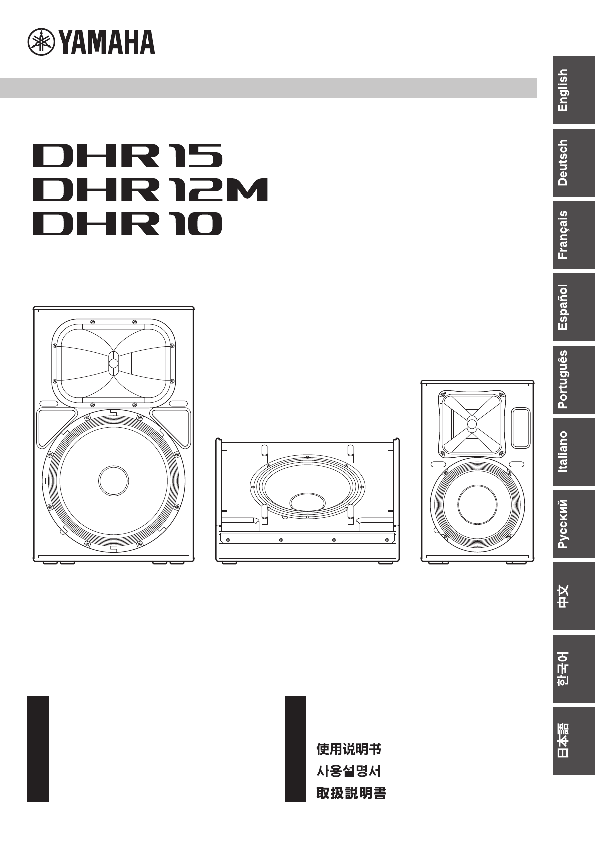
DHR Series

2
1. IMPORTANT NOTICE: DO NOT MODIFY THIS UNIT!
This product, when installed as indicated in the instructions con-
tained in this manual, meets FCC requirements. Modifications not
expressly approved by Yamaha may void your authority, granted
by the FCC, to use the product.
2. IMPORTANT: When connecting this product to accessories
and/or another product use only high quality shielded cables.
Cable/s supplied with this product MUST be used. Follow all
installation instructions. Failure to follow instructions could void
your FCC authorization to use this product in the USA.
3. NOTE: This product has been tested and found to comply with
the requirements listed in FCC Regulations, Part 15 for Class “B”
digital devices. Compliance with these requirements provides a
reasonable level of assurance that your use of this product in a
residential environment will not result in harmful interference with
other electronic devices. This equipment generates/uses radio
frequencies and, if not installed and used according to the
instructions found in the users manual, may cause interference
harmful to the operation of other electronic devices. Compliance
with FCC regulations does not guarantee that interference will not
occur in all installations. If this product is found to be the source of
interference, which can be determined by tur
ning the unit “OFF”
and “
ON”, please try to eliminate the problem by using one of the
following measures:
Relocate either this product or the device that is being affected by
the interference.
Utilize power outlets that are on different branch (circuit breaker
or fuse) circuits or install AC line filter/s.
In the case of radio or TV interference, relocate/reorient the
antenna. If the antenna lead-in is 300 ohm ribbon lead, change
the lead-in to co-axial type cable.
If these corrective measures do not produce satisfactory results,
please contact the local retailer authorized to distribute this type
of product. If you can not locate the appropriate retailer, please
contact Yamaha Corporation of America, Electronic Service Divi-
sion, 6600 Orangethorpe Ave, Buena Park, CA90620
The above statements apply ONLY to those products distributed
by Yamaha Corporation of America or its subsidiaries.
(class B)
FCC INFORMATION (U.S.A.)
(FCC SDoC)
COMPLIANCE INFORMATION STATEMENT
(Supplier’s declaration of conformity procedure)
Responsible Party : Yamaha Corporation of America
Address : 6600 Orangethorpe Ave., Buena Park, Calif. 90620
Telephone : 714-522-9011
Type of Equipment : POWERED SPEAKER SYSTEM
Model Name : DHR15, DHR12M, DHR10
This device complies with Part 15 of the FCC Rules.
Operation is subject to the following two conditions:
1) this device may not cause harmful interference, and
2) this device must accept any interference received including interference that may cause
undesired operation.
3
PRECAUTIONS
PLEASE READ CAREFULLY
BEFORE PROCEEDING
Please keep this manual in a safe place for
future reference.
WARNING
Always follow the basic precautions listed below to
avoid the possibility of serious injury or even death from
electrical shock, short-circuiting, damages, fire or other
hazards. These precautions include, but are not limited
to, the following:
If you notice any abnormality
• If any of the following problems occur, immediately turn off
the power switch and disconnect the electric plug from the
outlet.
- The power cord or plug becomes frayed or damaged.
- Unusual smells or smoke are emitted.
- Some object, or water has been dropped into the product.
- There is a sudden loss of sound during use of the product.
- Cracks or other visible damage appear on the product.
Then have the product inspected or repaired by qualified
Yamaha service personnel.
Power supply
• Do not place the power cord near heat sources such as
heaters or radiators, and do not excessively bend or
otherwise damage the cord, place heavy objects on it, or
place it in a position where anyone could walk on, trip over, or
roll anything over it.
• Only use the voltage specified as correct for the product. The
required voltage is printed on the name plate of the product.
• Use only the supplied power cord.
If you intend to use the product in an area other than in the
one you purchased, the included power cord may not be
compatible. Please check with your Yamaha dealer.
• Check the electric plug periodically and remove any dirt or
dust which may have accumulated on it.
• Make sure to fully insert the electric plug to prevent electric
shocks or fire.
• When setting up the product, make sure that the AC outlet
you are using is easily accessible. If some trouble or
malfunction occurs, immediately turn off the power switch
and disconnect the plug from the outlet. Even when the
power switch is turned off, as long as the power cord is not
unplugged from the wall AC outlet, the product will not be
disconnected from the power source.
• Remove the electric plug from the outlet when the product is
not to be used for extended periods of time.
• Do not touch the product or the electric plug during an
electrical storm.
• Be sure to connect to an appropriate outlet with a protective
grounding connection. Improper grounding can result in
electrical shock, fire, or damage.
Do not open
• This product contains no user-serviceable parts. Do not
attempt to disassemble the internal parts or modify them in
any way.
Water warning
• Do not expose the product to rain, use it near water or in
damp or wet conditions, or place on it any containers (such
as vases, bottles or glasses) containing liquids which might
spill into any openings.
• Never insert or remove an electric plug with wet hands.
Fire warning
• Do not place any burning items or open flames near the
product, since they may cause a fire.
Hearing loss
• Before turning the power of all devices on or off, make sure
that all volume levels are set to the minimum. Failing to do so
may result in hearing loss, electric shock, or device damage.
• When turning on the AC power in your audio system, always
turn on the product LAST, to avoid hearing loss and speaker
damage. When turning the power off, the product should be
turned off FIRST for the same reason.
CAUTION
Always follow the basic precautions listed below to
avoid the possibility of physical injury to you or others.
These precautions include, but are not limited to, the
following:
Power supply
• When removing the electric plug from the product or an
outlet, always hold the plug itself and not the cord. Pulling by
the cord can damage it.
Location and connection
• Do not place the product in an unstable position or a location
with excessive vibration, where it might accidentally fall over
and cause injury.
• Keep this product out of reach of children. This product is not
suitable for use in locations where children are likely to be
present.
• Do not block the vents. This product has ventilation holes at
the rear to prevent the internal temperature from becoming
too high. In particular, do not place the product on its side or
upside down. Inadequate ventilation can result in
overheating, possibly causing damage to the product(s), or
even fire.
• To ensure proper heat dissipation of the product, when
installing it:
- Do not cover it with any cloth.
- Do not use the product in a confined, poorly-ventilated
location.
Inadequate ventilation can result in overheating, possibly
causing damage to the product(s), or even fire. Make sure
that there is adequate space from the rear: at least 30 cm
above, 30 cm at the sides and 30 cm behind.
PA_en_12 1/2
4
• Do not place the product in a location where it may come into
contact with corrosive gases or salt air. Doing so may result in
malfunction.
• Before moving the product, remove all connected cables.
• When transporting or moving the DHR15, always use two or
more people. Attempting to lift the product by yourself may
result in injuries, such as back injuries, or cause the product
to be dropped and broken, which could lead to other injuries.
• Do not use the speaker’s handles for suspended installation.
Doing so can result in damage or injury.
• Do not hold the bottom of the product when transporting or
moving it. In doing so, you may pinch your hands under the
product, and result in injury.
• Do not press the rear panel of the product against the wall.
Doing so may cause the plug to come in contact with the wall
and detach from the power cord, resulting in short circuiting,
malfunction, or even fire.
• Always consult qualified Yamaha service personnel if the
product installation requires construction work.
Improper installation might cause accidents, injuries,
damage or malfunction of this product.
Maintenance
• Remove the power plug from the AC outlet when cleaning the
product.
Handling caution
• Do not insert your fingers or hands in any gaps or openings
on the product (ports).
• Do not rest your weight on the product or place heavy objects
on it.
• Do not operate the product if the sound is distorting.
Prolonged use in this condition could cause overheating and
result in fire.
(rear_en_01)
NOTICE
To avoid the possibility of malfunction/damage to the product or
damage to other property, follow the notices below.
Handling and maintenance
• Do not use the product in the vicinity of a TV, radio, or other
electric products. Otherwise, the product, TV, or radio may
generate noise.
• Do not expose the product to excessive dust or vibration,
or extreme cold or heat, in order to prevent the possibility
of panel disfiguration, unstable operation, or damage to
the internal components.
• Do not install in locations where temperature changes are
severe. Otherwise, condensation may form on the inside or
the surface of the product, causing it to break or deform
the wood. Do not leave condensation on the wood; wipe
immediately with a soft cloth.
• If there is reason to believe that condensation might have
occurred, leave the product for several hours without turn-
ing on the power until the condensation has completely
dried out, in order to prevent possible damage.
• Do not touch the speaker driver unit, since it might cause
malfunction.
• Air blowing out of the bass reflex ports (hole or holes at
the front) is normal, and often occurs when the speaker is
handling program material with heavy bass content.
• Do not place the speaker face down.
• When cleaning the product, use a dry and soft cloth. Do
not use paint thinners, solvents, cleaning fluids, or chemi-
cal-impregnated wiping cloths, since this might cause
alteration or discoloration.
• Always turn the power off when the device is not in use.
Information
About functions/data bundled with the prod-
uct
• Even when the [ / ] (power) switch is in standby status
(POWER indicator is off), electricity is still flowing to the
product at the minimum level. When you are not using the
product for a long time, make sure you unplug the power
cord from the wall AC outlet.
• XLR-type connectors are wired as follows (IEC60268 stan-
dard): pin 1: ground, pin 2: hot (+), and pin 3: cold (–).
About this manual
• The illustrations as shown in this manual are for instruc-
tional purposes only.
• The company names and product names in this manual
are the trademarks or registered trademarks of their
respective companies.
• Software may be revised and updated without prior notice.
About disposal
• This product contains recyclable components.
When disposing of this product, please contact the appro-
priate local authorities.
The model number, serial number, power requirements,
etc., may be found on or near the name plate, which is at
the rear of the unit. You should note this serial number in
the space provided below and retain this manual as a per-
manent record of your purchase to aid identification in the
event of theft.
Model No.
Serial No.
Yamaha cannot be held responsible for damage caused by
improper use or modifications to the product.
PA_en_12 2/2

5
Introduction
Thank you for purchasing the Yamaha DHR series Powered Loudspeaker. These products are designed
for live performance, sound reinforcement and fixed installation sound system applications. This manual
explains how to install, set up, and configure the connections for the installers, constructors, or general
users familiar with speakers. Please read this manual thoroughly before you begin using this product in
order to get the most out of its various functions. After reading this manual, please keep it available for
future reference.
Contents
PRECAUTIONS ..................................................................... 3
Introduction ........................................................................... 5
Main Features........................................................................ 5
Included Accessories............................................................ 5
Controls and Connectors ...................................................... 6
Setup Examples .................................................................... 9
Installation Examples...........................................................13
Troubleshooting ...................................................................14
General Specifications (English only)................................131
Block Diagram ...................................................................133
Dimensions ........................................................................134
Main Features
• Sophisticated DSP processing
Our proprietary sound-processing technology, called FIR-X Tuning, utilizes a linear-phase FIR filter—delivering excellent
sound quality with high resolution and a smooth frequency response that is unaffected by phase interference near the cross-
over point.
• Easy sound optimization
D-CONTOUR (Dynamic CONTOUR) constantly monitors the output of multiple frequency bands, and applies the optimum EQ
adjustments to each according to the listener’s preferences. There are two modes: an FOH/MAIN mode for use as a main
speaker, and a MONITOR mode for use as a floor monitor, letting you select the preset tuning optimized for each application.
• Various input/output connectors and convenient, simple mixing function
The comprehensive set of connectors—including XLR for a mixer, phone for a musical instrument, and RCA pin for an audio
player—provides maximum flexibility in use with a wide variety of applications. Also, the DHR features simple mixing function-
ality, enabling you to select either a direct output of channel 1 (CH1) (parallel connection) or a mixed output of CH1 and CH2,
for convenient system setup.
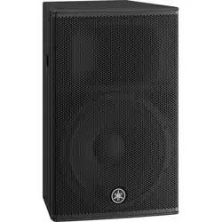
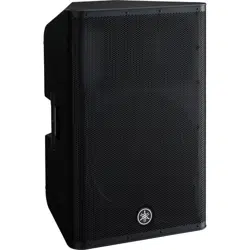
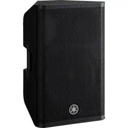
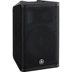
• Lineup for a variety of applications
The models are optimized for various applications: the DHR15 is ideal for use as a main speaker delivering powerful sound
and the DHR12M with its sound character optimized for monitoring is ideal for use as a compact floor monitor. The rotatable
horn equipped DHR10 is ideal for use as a fixed installation, and can be installed vertically or horizontally with optional brack-
ets.
• High-grade and durable wood cabinet for superior sound
The naturally textured wood cabinet of the DHR features a durable coating with high damage resistance to protect the cabinet
from scratches and bumps during transport, installations and removal.
Included Accessories
•AC power cord
• Owner’s manual (this book)
The example illustrations used in this manual are taken from the DHR15, if not otherwise specified.
NOTE
6
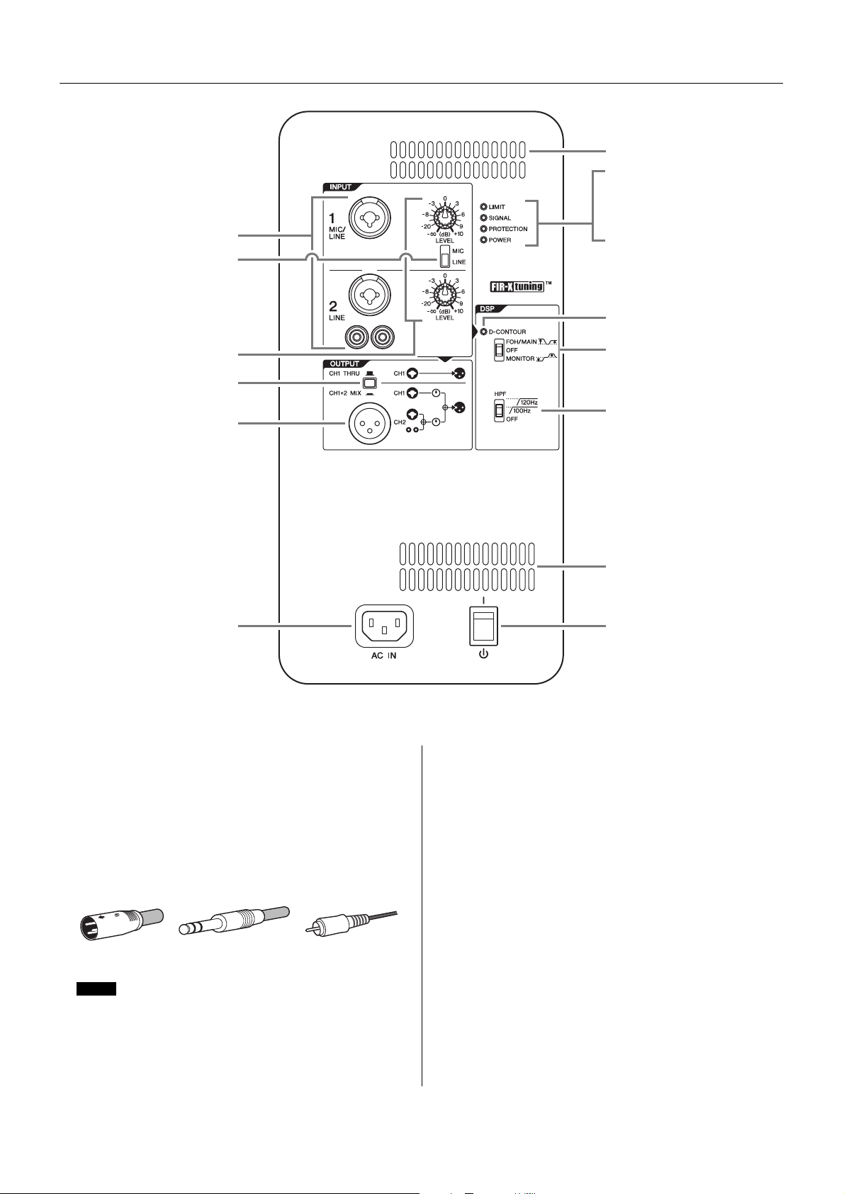
Controls and Connectors
q Input jacks (CH1 and CH2)
These are balanced combo jacks that support both XLR
and phone plugs (both CH1 and CH2), and RCA pin
plugs (CH2 only). For the combo jacks, connect a mixer,
microphone, or digital musical instrument such as a key-
board. For RCA-pin jacks, connect a device such as an
MP3 player or a CD player. For devices with high level sig-
nals such as a mixer, connect to CH2, or connect to CH1
then set the [MIC/LINE] switch (w) to [LINE].
w [MIC/LINE] switch
Set this switch to [MIC] or [LINE] for the CH1 jack,
depending on the level of the input signal. For low-level
signals (such as microphones), set the switch to [MIC].
For high-level signals (such as mixer), set the switch to
[LINE].
e [LEVEL] knobs
Adjust the level of each input jack (q).
r Output switch
Selects the output signal sent to the output jack (t).
[CH1 THRU]: Delivers the direct output signal of CH1 only.
Signal from CH2 will not be output.
[CH1+2 MIX]: Outputs the mixed signals of CH1 and CH2.
t Output jack
This is a balanced XLR jack. This can be used to connect
another DHR speaker. Outputs the signal selected by r
output switch.
!3
!3
!2
!1
y
u
i
o
!5
r
t
q
!0
!4
e
w
Rear
For CH2, inputs to the combo jack and to the RCA pin jacks will
be mono mixed at a fixed balance. If you want to change the bal-
ance, adjust the volume of the connected sound source.
XLR Phone RCA-pin
NOTE
7
Controls and Connectors
y [LIMIT] indicator
Indicates (lit in red) that the limiter is on when the output
voltage of the amplifier has exceeded the maximum level,
or when excessive integral power consumption is
detected. If this indicator stays lit, lower the input level.
u [SIGNAL] indicator
Indicates (lit in green) when an audio signal exceeding
the threshold has been detected.
i [PROTECTION] indicator
Indicates (lit in red) when the protection circuit is active.
The protection circuit will be activated and the speaker
outputs will be muted in the situations listed below.
• If amplifier overheating is detected
• If overcurrent is detected
• When turning the power on; the protection circuit will be
activated for a few seconds to prevent noise. The indi-
cator turns off when the power supply has started nor-
mally.
If the protection circuit has engaged, waiting until the
amplifier cools down or powering off and on again will
return to normal operation. If the unit does not return to
normal operation, please contact your Yamaha dealer.
o [POWER] indicator
Indicates (lit in green) when the [ / ] (power) (!5) switch
is turned on.
!0 [D-CONTOUR] indicator
Indicates (lit in yellow) when the [D-CONTOUR] switch
(!1) is set to [FOH/MAIN] or [MONITOR].
!1 [D-CONTOUR] switch
Selects one of the D-CONTOUR (Dynamic CONTOUR)
presets.
[FOH/MAIN]: Boosts the high and low frequency compo-
nents so that the frequency response is suitable for a
main speaker.
[MONITOR]: Reduces the low frequency range, which
could otherwise tend to be boomy if the speaker is set
directly on the floor. This enables you to hear mid and
high frequency ranges clearly when using as a floor
monitor.
[OFF]: Turns off D-CONTOUR. This is a generic frequency
response setting.
!2 [HPF] switch
Selects the cutoff frequency of the high pass filter. If you
set this switch to [120Hz] or [100Hz], the low frequency
components below each threshold will be cut. If you use
the unit alone, set this switch to [OFF]. If you plan to use
the unit along with a subwoofer, we recommend that you
set this switch to [120Hz] or [100Hz].
!3 Vent
The unit contains a cooling fan.
!4 [AC IN] socket
Connect the supplied power cord in the order below.
Before connecting the power cord, make sure that the
DHR power is turned off.
1. Insert the plug of the power cord into this socket.
2. Plug the other end of the cord into the AC outlet.
!5 [ / ] (power) switch
Turns the power supply on [ ] or sets it to standby [ ].
First, turn on the power of the connected sound source
(external device), then the unit. When turning off the
power, reverse the order by turning off the power of the
unit first and then the connected sound source (external
device).
Integral power consumption refers to the sum of power provided
to the speaker driver per unit time.
NOTE
CAUTION
Do not block the vents. This product has ventila-
tion holes at the rear to prevent the internal tem-
perature from becoming too high. Inadequate
ventilation can result in overheating, possibly
causing damage to the product(s), or even fire.
When removing the power cord, perform this procedure in
reverse order.
WARNING
Use only the supplied power cord.
CAUTION
Turn off the power before you connect or discon-
nect the power cord.
NOTICE
Even when the switch is in the standby position, a small
amount of electricity is still flowing to the unit.
• Rapidly turning the unit on and off in succession can cause it to
malfunction. After turning the unit off, wait for about 5 seconds
before turning it on again.
• If you are using multiple units, turn on the power to each unit
one by one. If you turn on the power to multiple units simultane-
ously, a temporary drop in the power voltage may occur, possi-
bly resulting in abnormal operation of the units.
NOTE
NOTE
8
Controls and Connectors
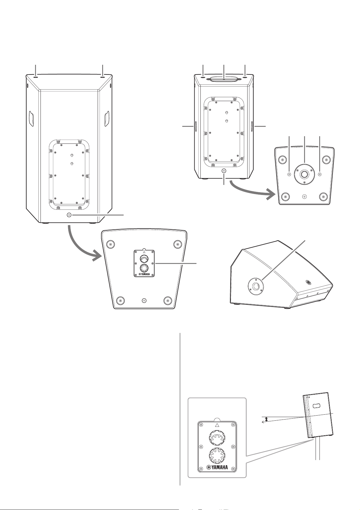
!6 Screw holes for U-bracket M8 (DHR10 only)
For installing with the separately sold U-brackets.
!7 Screw holes for eye bolts M10
(DHR15 and DHR10 only)
For installing the speaker using commercially available
eye bolts (M10).
!8 Pole socket
This socket adapts to commercially available speaker
stands and speaker poles of 35 mm diameter.
Tiltable pole socket (DHR15 only)
This mount has two pole sockets. You can choose the
angle of the speaker so that it is positioned horizontal to
the floor or tilting down toward the floor by 7 degrees.
FRONT
7°
0°
!6
!8!6 !6
!7 !7
!7
!7!7
!6
!7
!8
!6
!8
Rear (DHR15) Rear (DHR10)
Bottom
Side
(DHR12M)
Bottom
FRONT
7°
0°
7°
Tiltable pole socket
9
Setup Examples
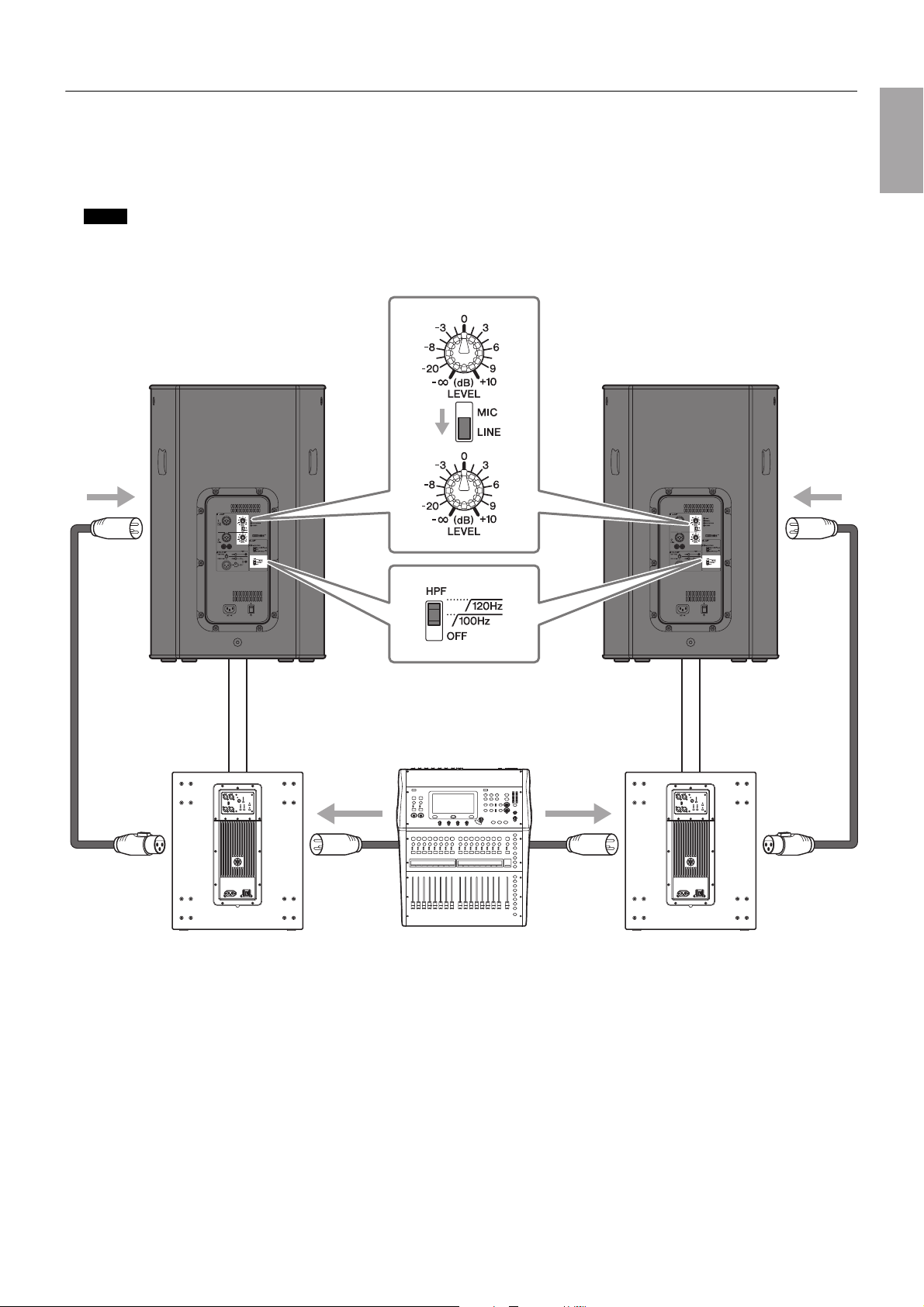
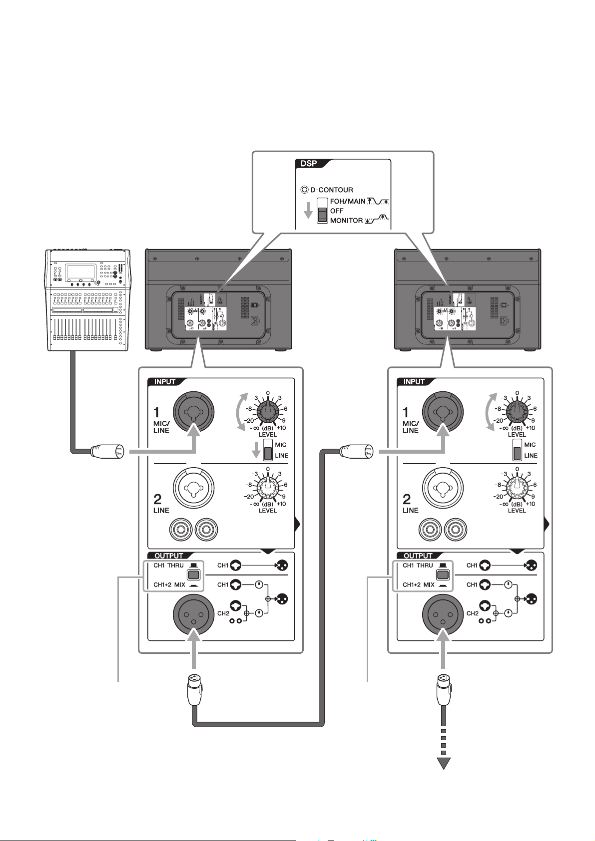
System with two DHRs and subwoofers—using the DHR15
This system is the most suitable for a main speaker system. If desired, you can add other DHR12M to create a floor monitor sys-
tem.
Main application: small-sized live venue, house of worship, event site
We recommend to use Yamaha DXS18 as a subwoofer. In this case, we recommend that the DHR15’s HPF cutoff frequency and the DXS18’s
LPF cutoff frequency are set to the same settings; however, you can adjust it as desired.
NOTE
Subwoofer Subwoofer Mixer
LR
10
Setup Examples
Floor monitor system—using the DHR12M
This system is suitable for a performer’s monitoring system. For use as a vocal monitor, set the [D-CONTOUR] switch to [MONI-
TOR].
If necessary, you can additionally connect up to four speakers in parallel. In this case we recommend that the signal is input to
CH1 and the output switch is set to [CH1 THRU].
Mixer
Set to [CH1 THRU] Set to [CH1 THRU]
To next speaker
11
Setup Examples
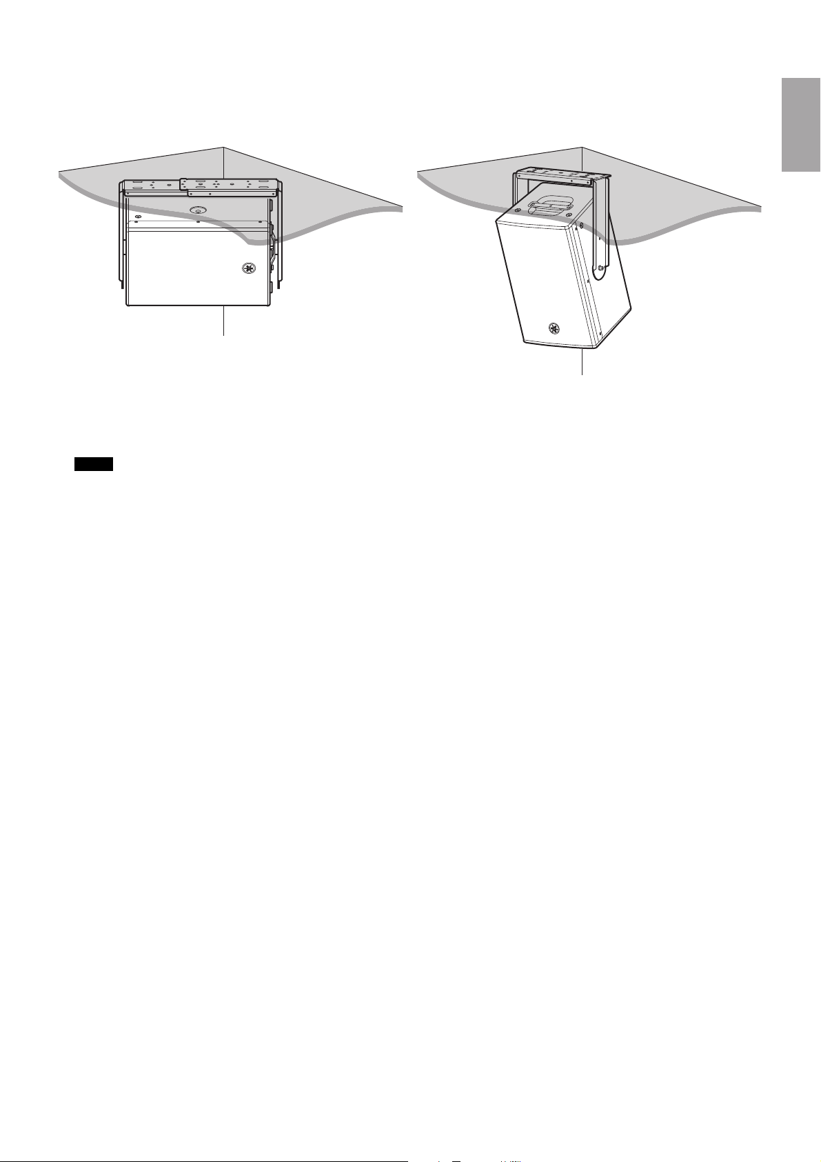
Fixed installations—using the DHR10
DHR10 can be neatly installed on a ceiling or a wall, either horizontally or vertically, with the separately sold Yamaha UB-
DXRDHR10 U-bracket. For instructions on installing the U-bracket, refer to the corresponding manual for the UB-DXRDHR10.
Also, the DHR10 features a rotatable horn (90 degrees). When shipped from the factory, the directivity of DHR10 in a vertical ori-
entation is the setting which makes the sound expand in a horizontal direction, and inhibits or narrows the sound in a vertical
direction. We recommend changing the directivity by rotating the horn when you want to install the DHR10 horizontally and
broaden the directivity.
The UB-DXRDHR10 can be used together with separately sold optional brackets, such as the Yamaha BBS251 Baton Bracket.
NOTE
12
Setup Examples
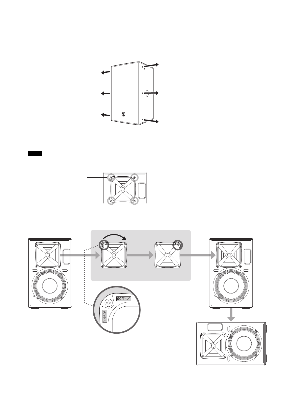
Rotatable Horn (DHR10 only)
1. Using a No. 2 Phillips head screwdriver, remove all fixing screws on the grille, and remove the grille from the speaker.
2. Using a No. 2 Phillips head screwdriver, remove all screws installed on the horn and pull the horn out from the speaker.
3. Rotate the horn 90 degrees, and re-install the horn to the speaker, reversing the steps above.
Make sure not to push the screws too strongly with the Phillips head screwdriver. This may cause the nuts inside the cabinet to fall off.
NOTE
Screws (four total)
Vertical
Rotate 90°
Horizontal
13
Installation Examples
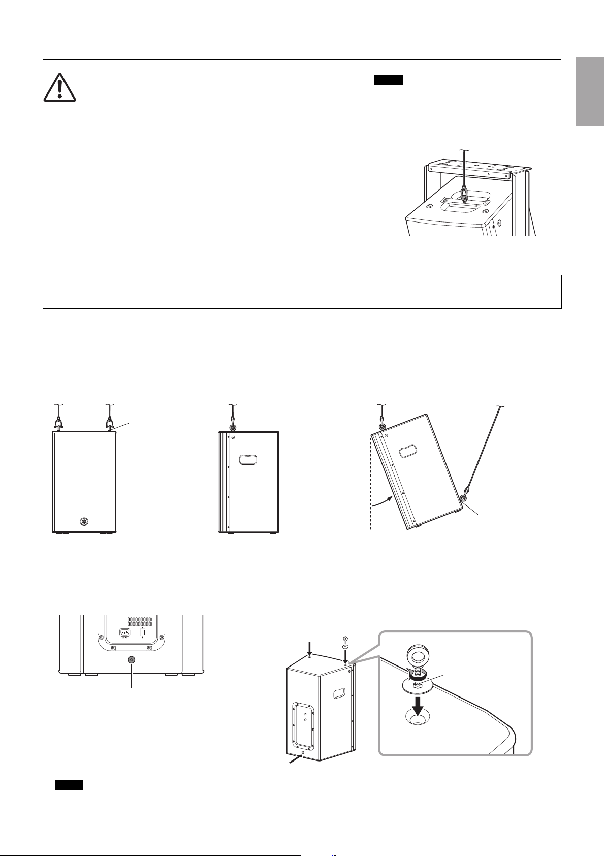
Suspended Installation Using Eye Bolts (DHR15 and DHR10 only)
Attach commercially available long eye bolts (30–50 mm in length) to the screw holes located at the top (two locations) and on
the lower rear (one location). The screw diameter is M10. Keep in mind that you will need two points at the top to suspend the
unit.
Yamaha cannot be held responsible for damage or injury caused by insufficient strength of the support structure or
improper installation.
The screw holes for eye bolts go through the cabinet wall. When not using eye bolts, tighten the flat-head screws in order to prevent air leaks.
CAUTION
• Before doing any installation or construction work, consult with your
Yamaha dealer.
• The installation should be checked thoroughly at regular intervals.
Some fittings may deteriorate over extended periods of time due to
wear and/or corrosion.
• When choosing the installation location, suspension wire and
mounting hardware, make sure all are strong enough to support the
weight of the speaker.
• Make sure to take precautionary measures using wires to prevent the
speaker from falling down in the event of an installation failure.
• When installing the safety wire to the wall, install it higher than the
wire’s attachment point on the speaker, with as little slack as possi-
ble. If the wire is too long, and the speaker happens to fall, the wire
may snap as a result of too much strain.
• Make sure to use eye bolts according to the standards and safety
regulations in your area.
Safety wire can be attached to the screw holes for
eye bolts and to the screw holes for the U-bracket
(DHR10 only) located at the center of the handle.
The illustration below is an example of using the U-
bracket.
NOTE
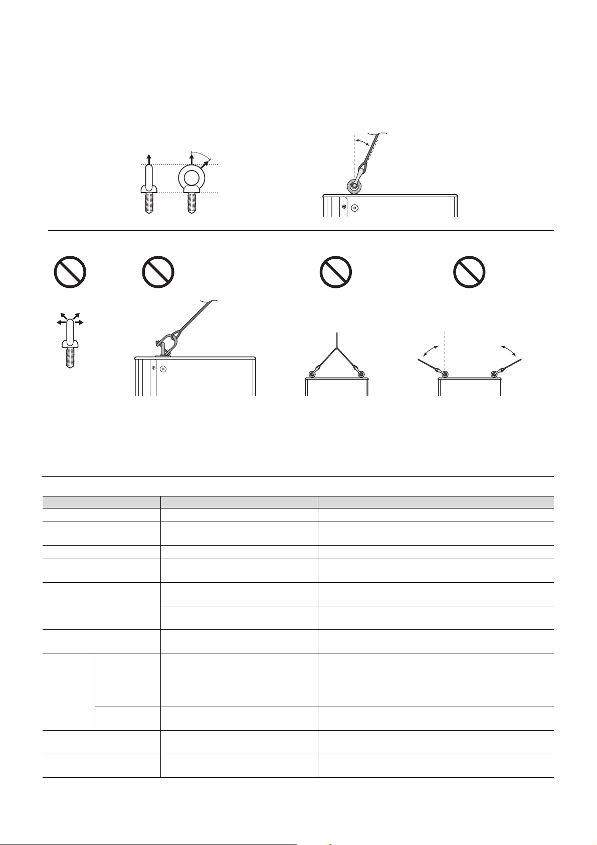
M10 eye bolt
Max. 45°
Pullback point
Pullback point
Pullback point
(M10 screw hole)
Lower rear
Securing the eye bolts
Remove the flat-head screws tightened at the time of factory shipment,
and then insert the eye bolts through the washers when attaching
them.
Apply thread-locking
fluid to the eye bolt
NOTE
14
Tro ubleshooting
Suspension angle
The strength of an eye bolt differs depending on the suspension angle. Make sure to use eye bolts within a range of 0 to 45
degrees from a right angle (as shown).
Troubleshooting
If any specific problem should persist, however, please contact your Yamaha dealer.
Symptom Possible causes Possible solution
Power does not turn on. The power cord is not connected properly. Connect the power cord all the way in so that it is firmly in place.
Power suddenly went off.
The protection system has been acti-
vated, shutting down the power supply.
Turn off the power, wait until the amplifier cools down, and then
turn on again.
No Sound. The cable is not connected properly. Connect the cable all the way in so that it is firmly in place.
Sound is interrupted suddenly.
The protection circuit has been activated,
muting the output.
Wait until the amplifier cools down. If the unit won’t automatically
reset itself, turn off the power, and then on again.
Sound howls (feedback).
A microphone is directed toward the
speaker.
Aim the speaker away from the area where the microphone
picks up sound.
Sound is amplified too much.
Lower the volume of input device and locate the microphone
more closely to the sound source.
Each speaker sound differs
(if multiple speakers are used).
Settings for each speaker differ.
Set the [HPF] switch and [D-CONTOUR] switch of each speaker
to the same positions.
Sound is
distorted.
The [LIMIT]
indicator is off.
Input volume is excessive.
When the [MIC/LINE] switch is set to [MIC], and even if you
lower the volume fully the sound is still distorted, set the switch
to the [LINE] position. If the sound is still distorted even if the
switch has been set to [LINE], lower the volume of the con-
nected input devices.
The [LIMIT]
indicator is on.
Output volume is excessive.
Turn the [LEVEL] knob to lower the output level to a point so that
the [LIMIT] indicator lights only occasionally.
The microphone volume is too
low.
The [MIC/LINE] switch is set to [LINE]. Set the [MIC/LINE] switch to the [MIC] position.
Low and high frequency are
unbalanced.
The output limiter is active.
Lower the input level or the output level until the [LIMIT] indica-
tor lights occasionally.
0°
45°
Max. 45°
Correct: Within 45° from a right angle
Incorrect: Do not suspend the eye bolts as shown in the illustrations below.
Prohibited
Only one
suspension point
More than 45° from
a right angle
More than
45°
More than
45°
Prohibited Prohibited Prohibited
131
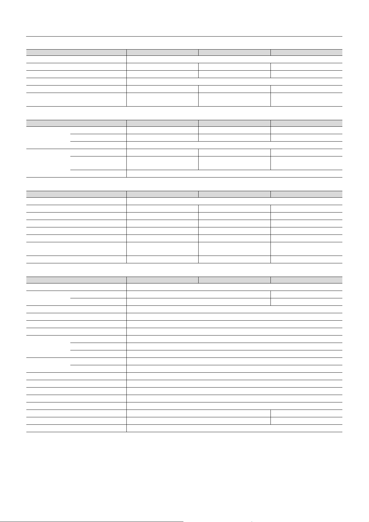
General Specifications
0 dBu is referenced to 0.775 Vrms.
*1 Power rating (120 V, 25°C). This is total value of individual output power.
This value is measured by releasing the software protection.
Dynamic: Total peak power of individual outputs. Measured at minimum load impedance, with protection released.
Continuous: Measured at nominal impedance, with protection activated.
General DHR15 DHR12M DHR10
System Type 2-way, Bi-amp Powered Speaker, Bass-reflex Type
Frequency Range (-10 dB) 44 Hz–20 kHz 55 Hz–20 kHz 52 Hz–20 kHz
Coverage Angle H90° × V60° H90° × V90° H90° × V60° (Rotatable)
Crossover Type FIR-X tuning (Linear Phase FIR Filter)
Crossover Frequency 1.8 kHz 1.8 kHz 1.9 kHz
Measured Maximum SPL (Peak)
IEC noise@1m
131 dB SPL 129 dB SPL 128 dB SPL
Transducer DHR15 DHR12M DHR10
LF Diameter 15" Cone 12" Cone 10" Cone
Voice coil 2.5" 2.5" 2"
Magnet Ferrite
HF Diaphragm 1.4" 1.75" 1.4"
Type
1" Throat Compression Driver
1" Throat Compression Driver
Coaxial
1" Throat Compression Driver
Magnet Ferrite
Enclosure DHR15 DHR12M DHR10
Material, Color Plywood, Black, Polyurea coating
Floor Monitor Angle — 57° —
Dimensions (W×H×D, with rubber feet) 432 × 692 × 405 mm 500 × 343 × 454 mm 305 × 494 × 300 mm
Net Weight 24.0 kg 16.5 kg 15.0 kg
Handles Side × 2 Side × 1 Top × 1
Pole Socket 35 mm × 2 (0 and 7 degree) 35 mm 35 mm
Rigging Points Top × 2, Rear × 1
(Fit for M10 Eyebolts)
—
Top × 2, Rear × 1
(Fit for M10 Eyebolts)
Optional Speaker Bracket — — UB-DXRDHR10
Amplifier DHR15 DHR12M DHR10
Amplifier Type Class-D
Power Rating
*1
Dynamic 1000 W (LF: 800 W, HF: 200 W) 700 W (LF: 500 W, HF: 200 W)
Continuous 465 W (LF: 400 W, HF: 65 W) 325 W (LF: 260 W, HF: 65 W)
Cooling Fan Cooling, 4 Speeds.
AD/DA 24 bit 48 kHz Sampling
HPF OFF, 100 Hz, 120 Hz, 24 dB/Oct.
DSP Preset D-CONTOUR: FOH/MAIN, MONITOR, OFF
Protection Speaker Clip Limiting, Integral Power Protection, DC-fault
Amplifier Thermal, Output Over Current
Power Supply Thermal, Output Over Voltage, Output Over Current
Connectors Input Input1: Combo × 1, Input2: Combo × 1, RCA PIN × 2 (Unbalanced)
Output Output: XLR3-32 × 1 (CH1 Parallel Through or CH1+CH2 Mix)
Input Impedance INPUT1: LINE: 10 kΩ, MIC: 3 kΩ, INPUT2: 10 kΩ
Input Sensitivity (LEVEL: Maximum) INPUT1: LINE: 0 dBu, MIC: -32 dBu, INPUT2: 0 dBu
Input Sensitivity (LEVEL: Center) INPUT1: LINE: +10 dBu, MIC: -22 dBu, INPUT2: +10 dBu
Maximum Input Level INPUT1: LINE: +24 dBu, MIC: -8 dBu, INPUT2: +24 dBu
Controls LEVEL × 2, LINE/MIC, HPF, D-CONTOUR, THRU/MIX, POWER
Idle Power Consumption 18 W 18 W
1/8 Power Consumption 74 W 60 W
Power Requirements 100 V, 110–120 V, 220–240 V, 110 V/127 V/220 V (Brazil), 50/60 Hz
General Specifications (English only)

132
General Specifications
* The contents of this manual apply to the latest specifications as of the publishing date. To obtain the latest manual, access the
Yamaha website then download the manual file.
* Der Inhalt dieser Bedienungsanleitung gilt für die neuesten technischen Daten zum Zeitpunkt der Veröffentlichung. Um die
neueste Version der Anleitung zu erhalten, rufen Sie die Website von Yamaha auf und laden Sie dann die Datei mit der Bedie-
nungsanleitung herunter.
* Le contenu de ce mode d’emploi s’applique aux dernières caractéristiques techniques connues à la date de publication du man-
uel. Pour obtenir la version la plus récente du manuel, accédez au site Web de Yamaha puis téléchargez le fichier du manuel
co
ncerné.
* El
contenido de este manual se aplica a las últimas especificaciones según la fecha de publicación. Para obtener el último man-
ual, acceda al sitio web de Yamaha y descargue el archivo del manual.
* O conteúdo deste manual se aplica às especificações mais recentes a partir da data de publicação. Para obter o manual mais
recente, acesse o site da Yamaha e faça o download do arquivo do manual.
* Il contenuto del presente manuale si applica alle ultime specifiche tecniche a partire dalla data di pubblicazione. Per ottenere la
versione più recente del manuale, accedere al sito Web Yamaha e scaricare il file corrispondente.
* В содержании данного руководства приведены последние на момент публикации технические характеристики. Для
получения последней версии руководства посетите веб-сайт корпорации Yamaha и загрузите файл с руководством.
* 본 설명서의 내용은 발행일 현재 최신 사양을 기준으로 하고 있습니다. 최신 설명서를 가져오려면 Yamaha 웹사이트에 접속
후 해당 설명서 파일을 다운로드받으십시오.
* 本書は、発行時点での最新仕様で説明しています。最新版は、ヤマハウェブサイトからダウンロードできます。
133
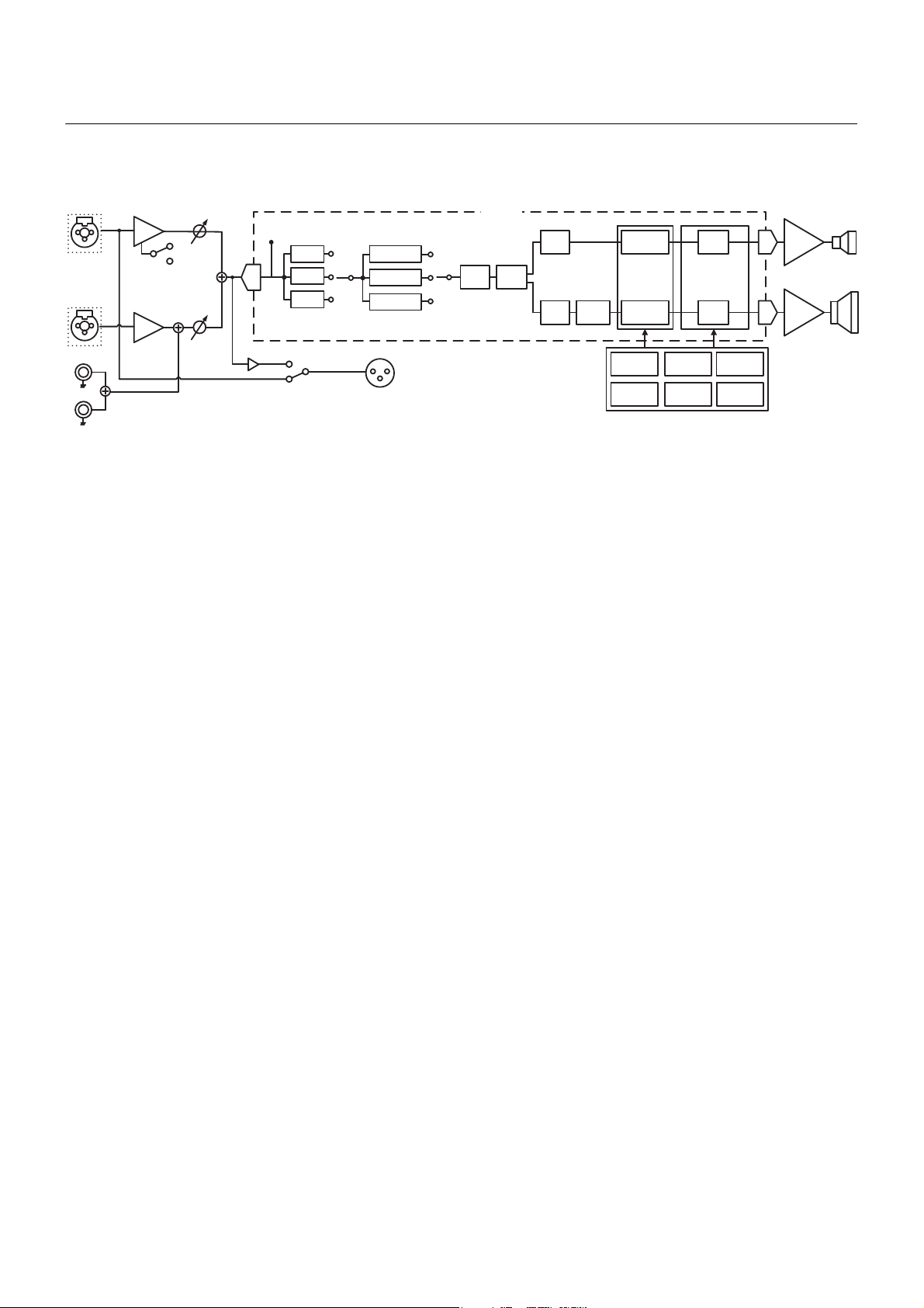
Block Diagram
电路图
●PROTECTION
●LIMIT
1 (MIC/LINE)
120Hz
Limiter
SIGNAL
EQ
FIR-X
Delay Limiter
Amp.
(HF)
Amp.
(LF)
Mute
Mute
Tem p. DC-fault
Output
Current
Output
Voltage
Integral
Output
Power
On/Off
Mute
Protection Logic
EQ
EQ
MONITOR
D-CONTOUR
FOH/MAIN
OFF
HPF
100Hz
OFF
OUTPUT
HF
LF
INPUT
AD
DA
DA
DSP
HF
LF
HA
MIC/LINE
LEVEL
HA
LEVEL
2 (LINE)
Pin
Combo
(Balance)
Combo
(Balance)
(CH1 THRU)
(CH1+2 MIX)
134
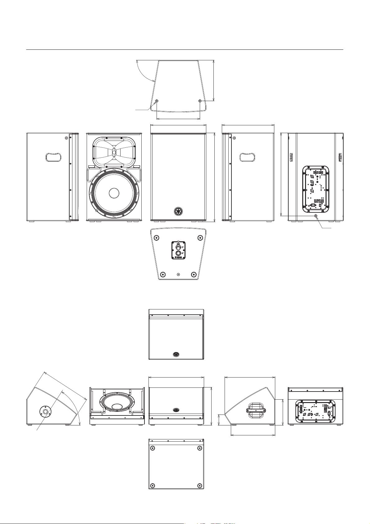
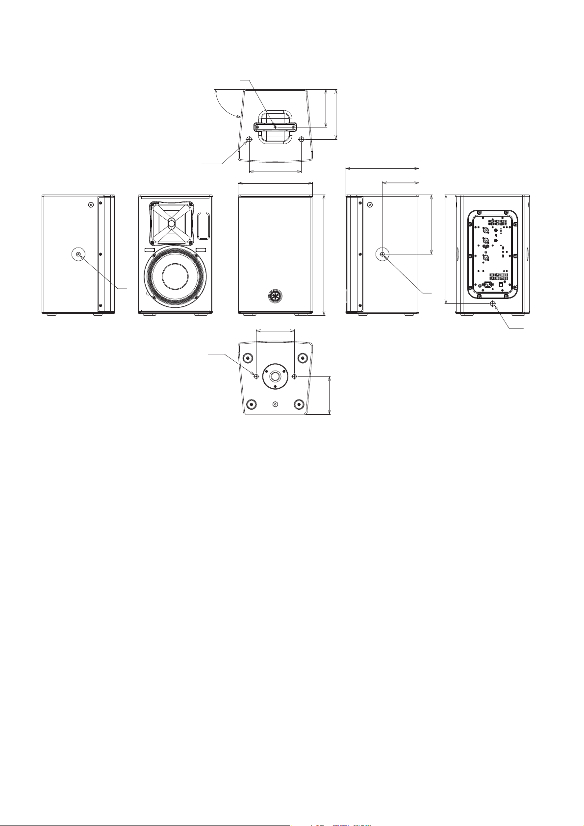
Dimensions
外形尺寸
80°
2×M10
336
317
432
692
M10
644
405
DHR15
Unit: mm
単位:mm
232
95
454
400
343
500
458
57°
DHR12M
Unit: mm
単位:mm
135
Dimensions
305
494
2×M8
156
155
M8
243.5
150
300
M8
2×M10
M8
214
205
155
85°
M10
446
DHR10
Unit: mm
単位:mm
136
137
(weee_eu_en_02)
(weee_eu_de_02)
(weee_eu_fr_02)
Information for users on collection and disposal of old equipment:
This symbol on the products, packaging, and/or accompanying documents means that used electrical and elec-
tronic products should not be mixed with general household waste.
For proper treatment, recovery and recycling of old products, please take them to applicable collection points, in
accordance with your national legislation.
By disposing of these products correctly, you will help to save valuable resources and prevent any potential negative
effects on human health and the environment which could otherwise arise from inappropriate waste handling.
For more information about collection and recycling of old products, please contact your local municipality, your
waste disposal service or the point of sale where you purchased the items.
For business users in the European Union:
If you wish to discard electrical and electronic equipment, please contact your dealer or supplier for further inf
orma-
tion.
Information on Disposal in other Countries outside the European Union:
This symbol is only valid in the European Union. If you wish to discard these items, please contact your local author-
ities or dealer and ask for the correct method of disposal.
Verbraucherinformation zur Sammlung und Entsorgung alter Elektrogeräte
Befindet sich dieses Symbol auf den Produkten, der Verpackung und/oder beiliegenden Unterlagen, so sollten
benutzte elektrische Geräte nicht mit dem normalen Haushaltsabfall entsorgt werden.
In Übereinstimmung mit Ihren nationalen Bestimmungen bringen Sie alte Geräte bitte zur fachgerechten Entsor-
gung, Wiederaufbereitung und Wiederverwendung zu den entsprechenden Sammelstellen.
Durch die fachgerechte Entsorgung der Elektrogeräte helfen Sie, wertvolle Ressourcen zu schützen, und verhin-
dern mögliche negative Auswirkungen auf die menschliche Gesundheit und die Umwelt, die andernfalls durch
unsachgerechte Müllentsorgung auftreten könnten.
Für weitere Informationen zum Sammeln und Wieder
aufbereiten alter Elektrogeräte kontaktieren Sie bitte Ihre örtli-
che Stadt- oder Gemeindeverwaltung, Ihren Abfallentsorgungsdienst oder die Verkaufsstelle der Artikel.
Information für geschäftliche Anwender in der Europäischen Union:
Wenn Sie Elektrogeräte ausrangieren möchten, kontaktieren Sie bitte Ihren Händler oder Zulieferer für weitere Infor-
mationen.
Entsorgungsinformation für Länder außerhalb der Europäischen Union:
Dieses Symbol gilt nur innerhalb der Europäischen Union. Wenn Sie solche Artikel ausrangieren möchten, kontak-
tieren Sie bitte Ihre örtlichen Behörden oder Ihren Händler und fragen Sie nach der sachgerechten Entsorgungsme-
thode.
Informations concernant la collecte et le traitement des déchets d’équipements électriques et électroniques
Le symbole sur les produits, l’emballage et/ou les documents joints signifie que les produits électriques ou électro-
niques usagés ne doivent pas être mélangés avec les déchets domestiques habituels.
Pour un traitement, une récupération et un recyclage appropriés des déchets d’équipements électriques et électro-
niques, veuillez les déposer aux points de collecte prévus à cet effet, conformément à la réglementation nationale.
En vous débarrassant correctement des déchets d’équipements électriques et électroniques, vous contribuerez à la
sauvegarde de précieuses ressources et à la prévention de potentiels effets négatifs sur la santé humaine qui pour-
raient advenir lors d’un traitement inapproprié des déchets.
Pour plus d’informat
ions à propos de la collecte et du recyclage des déchets d’équipements électriques et électroni-
ques, veuillez contacter votre municipalité, votre service de traitement des déchets ou le point de vente où vous
avez acheté les produits.
Pour les professionnels dans l’Union européenne :
Si vous souhaitez vous débarrasser des déchets d’équipements électriques et électroniques, veuillez contacter
votre vendeur ou fournisseur pour plus d’informations.
Informations sur la mise au rebut dans d’autres pays en dehors de l’Union européenne :
Ce symbole est seulement valable dans l’Union européenne. Si vous souhaitez vous débarrasser de déchets
d’équipements
électriques et électroniques, veuillez contacter les autorités locales ou votre fournisseur et deman-
der la méthode de traitement appropriée.
138
(weee_eu_es_02)
(weee_eu_pt_02a)
(weee_eu_it_02)
Información para usuarios sobre la recogida y eliminación de los equipos antiguos
Este símb olo en los productos, embalajes y documentos anexos significa que los productos eléctricos y electróni-
cos no deben mezclarse con los desperdicios domésticos normales.
Para el tratamiento, recuperación y reciclaje apropiados de los productos antiguos, llévelos a puntos de reciclaje
correspondientes, de acuerdo con la legislación nacional.
Al deshacerse de estos productos de forma correcta, ayudará a ahorrar recursos valiosos y a impedir los posibles
efectos desfavorables en la salud humana y en el entorno que de otro modo se producirían si se trataran los des-
perdicios de modo inapropiado.
Para obtener más información acerca de la recogida y el reciclaje de los productos antiguos, póngase en contacto
con las autoridades locales, con el servicio de eliminación de basuras o con el punto de venta donde adquirió los
artículos.
Para los usuarios empresariales de la Unión Europea:
Si desea desechar equipos eléctricos y electrónicos, póngase en contacto con su vendedor o proveedor para obte-
ner más información.
Información sobre la eliminación en otros países fuera de la Unión Europea:
Este símb olo solo es válido en la Unión Europea. Si desea desechar estos artícul
os, póngase en contacto con las
autoridades lo
cales o con el vendedor y pregúnteles el método correcto.
Informações para os utilizadores relativas à recolha e eliminação de equipamentos usados
Este símb olo, presente em produtos, embalagens e/ou incluído na documentação associada, indica que os produ-
tos elétricos e eletrónicos usados não devem ser eliminados juntamente com os resíduos domésticos em geral.
O procedimento correto consiste no tratamento, recuperação e reciclagem de produtos usados, pelo que deve pro-
ceder à respetiva entrega nos pontos de recolha adequados, em conformidade com a legislação nacional em vigor.
A eliminação destes produtos de forma adequada permite poupar recursos valiosos e evitar potenciais efeitos pre-
judiciais para a saúde pública e para o ambiente, associados ao processamento incorreto dos resíduos.
Para mais informações relativas à recolha e reciclagem de produtos usados, contacte as autoridades locais, o ser-
viço de eliminação de resíduos ou o ponto de venda onde foram adquiridos os itens relevantes.
Informações para utilizadores empresariais na União Europeia:
Para proceder à eliminação de equipamento elétrico e eletrónico, contacte o seu revendedor ou fornecedor para
obter informações adicionais.
Informações relativas à eliminação em países não pertencentes à União Europeia:
Este símb olo é válido exclusivamente na Un
ião Europeia. Caso pretenda eliminar este tipo de itens, contacte as
autoridades locais ou o seu revendedor e informe-se acerca do procedimento correto para proceder à respetiva eli-
minação.
Informazioni per gli utenti sulla raccolta e lo smaltimento di vecchia attrezzatura
Questi simboli sui prodotti, sull’imballaggio e/o sui documenti che li accompagnano, indicano che i prodotti elettrici
ed elettronici non devono essere mischiati con i rifiuti generici.
Per il trattamento, il recupero e il riciclaggio appropriato di vecchi prodotti, si prega di portarli ai punti di raccolta desi-
gnati, in accordo con la legislazione locale.
Smaltendo correttamente questi prodotti si potranno recuperare risorse preziose, oltre a prevenire potenziali effetti
negativi sulla salute e l’ambiente che potrebbero sorgere a causa del trattamento improprio dei rifiuti.
Per ulteriori informazioni sulla raccolta e il riciclaggio di vecchi prodotti, si prega di contattare l’amministrazione
comunale locale, il servizio di smaltimento dei rifiuti o il punto vendita dove sono stati acquistati gli articoli.
Per utenti imprenditori dell’Unione europea:
Se si desidera scartare attrezzatura elettrica ed elettronica, si prega di contattare il proprio rivenditore o il proprio for-
nitore per ulteriori informazioni.
Informazioni sullo smaltimento negli altri Paesi al di fuori dell’Unione europea:
Questi simboli sono validi solamente nell’Unione Europea; se si desidera scartare questi articoli, si prega di contat-
tare le autorità locali o il rivenditore e richiedere informazioni sulla corretta modalità di smaltimento.
139
Yamaha Pro Audio global website
http://www.yamahaproaudio.com/
Yamaha Downloads
https://download.yamaha.com/
VDK0300
Manual Development Group
© 2021 Yamaha Corporation
Published 04/2021
2021年4月
发行
POIN - A1