Loading ...
Loading ...
Loading ...
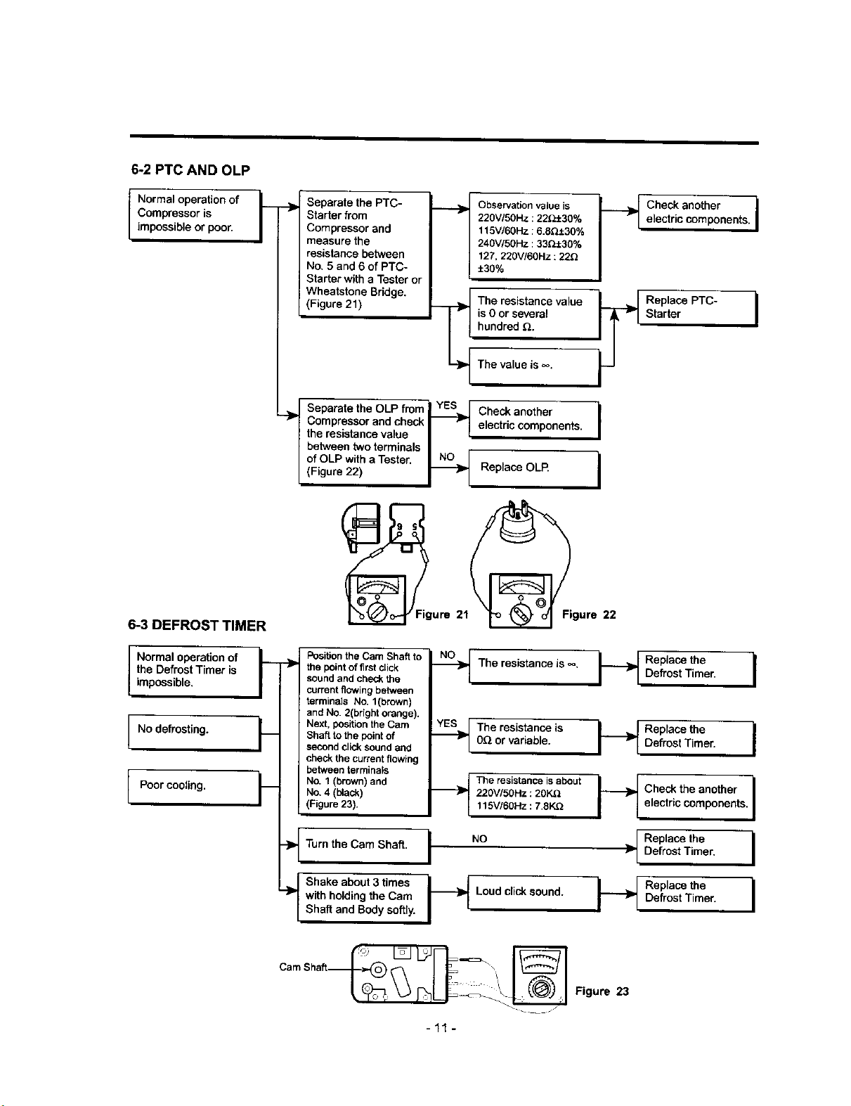
6-2 PTC AND OLP
Normal operation of y
Compressor is -'_
/
impossible or poor.
6-3 DEFROST TIMER
Separate the PTC-
Starter from
Compressor and
measure the
resistance between
No, 5 and 6 of PTC-
Starter with a Tester or
Wheatstone Bridge.
(Figure 21)
Observation value is
220V150Hz : 22_±30%
115V/60Hz : 6.8Q.t30%
240V/5OHz :33_±30%
127, 220V/60Hz : 22_
±30%
Th_resiste naC_ value
iS .
__ Check another j
electric components. |
t Separate the OLP fmm_ YES I Check another
check_ _'_] electric components. I
Compressor
and
the resistance value I I
between two terminals I
of OLP with a Tester. _ i
(Figure 22) _ v I Replace OLP.
Normal operation of __ .._
the Defrost Timer is
/
impossible,
No defrosting.
Poorcooling.
k
..>
Position the Cam Shaft to
the point of first click
sound and check the
current flowing between
terminals No. 1(brown)
and NO. 2(bright orange).
Next, position the Cam
Shaft to the point of
second click sound and
check the current flowing
between terminals
No. 1 (brown) and
No, 4 (black)
(Figure 23).
--_ The resistance is _, I_
.._ The resistance is
0_ or variable.
._t The resistance isabout
220V/50Hz : 20K.G
115V/60Hz : 7.8K.Q
Turnthe Cam Shaft. I NO
f Shake about 3 times I_
with holding the Cam Loud click sound.
Shaft and Body softly.
Replace the I
Defrost Timer.
Replacethe I
DefrostTimer.
I-----_ Check the another I
electric components, I
__[ Replace the
Defrost Timer, I
I _[ DRee_'OaSCteTtihrTeer" I
-11-
Figure 23
Loading ...
Loading ...
Loading ...