Loading ...
Loading ...
Loading ...
6ENGLISH
Indicator lamps Remaining
capacity
Lighted O Blinking
75% to 100%
50% to 75%
25% to 50%
0% to 25%
Charge the
battery.
The battery
may have
malfunctioned.
NOTE: Depending on the conditions of use and the
ambient temperature, the indication may dier slightly
from the actual capacity.
NOTE: The rst (far left) indicator lamp will blink when
the battery protection system works.
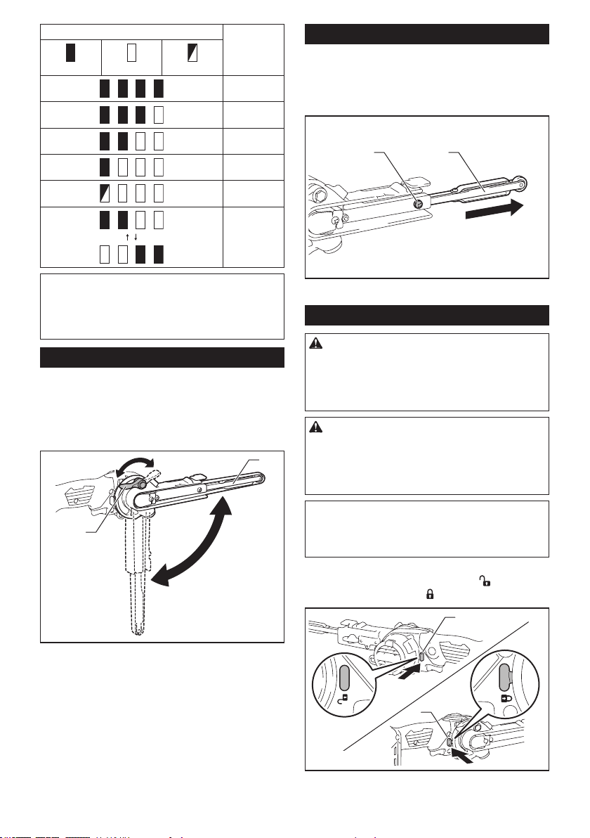
Adjusting arm inclination
The arm can be pivoted and xed at any desired angle
within the range "A" (-5° to 90°) in the gure. Adjust the
angle to make a comfortable working position.
Loosen the lock lever by raising it. Pivot the arm to the
desired position, and secure the lock lever to x the arm
rmly.
“A”
1
2
► 1. Lock lever 2. Arm
Replacing arm
6 mm (1/4″) and 13 mm (1/2″) width belts can be
installed with the optional arms that are designed for
the corresponding belt widths. Loosen the screw that
secures the arm and replace the standard-equipped
arm with the optional arm, then tighten the screw rmly.
1 2
► 1. Screw 2. Arm
Switch action
WARNING:
For your safety, this tool is equipped
with the lock-o switch which prevents the tool from
unintended starting. NEVER use the tool if it runs when
you simply pull the switch trigger without releasing the
lock-o switch. Return the tool to our authorized ser-
vice center for proper repairs BEFORE further usage.
CAUTION: Before installing the battery car-
tridge into the tool, always check to see that the
switch trigger actuates properly and returns to
the "OFF" position when released. Operating a tool
with a switch that does not actuate properly can lead
to loss of control and serious personal injury.
NOTICE:
Do not pull the switch trigger hard without
releasing the lock-o switch. This can cause switch breakage.
NOTICE: The lock-o switch cannot be released
while the arm is being pivoted beyond 90°.
To prevent the switch trigger from being accidentally pulled, a lock-
o switch is provided. Depress the switch lever ( ) from the A side
to unlock the switch trigger, and ( ) from the B side to lock in.
A
B
1
1
► 1. Lock-o switch
Loading ...
Loading ...
Loading ...