Write the model and serial
numbers here:
Model # _________________
Serial # _________________
You can find the this information
on a label attached to the right
side of the chassis.
GE is a trademark of the General Electric Company. Manufactured under trademark license.
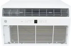
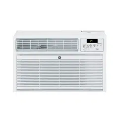
AIR CONDITIONER
24” Through-the-Wall
49-5000712 Rev. 1 08-22 GEA
ESPAÑOL
For a Spanish version of this
manual, visit our Website at
www.GEAppliances.com.
Para consultar una version
en español de este manual
de instrucciones, visite nuestro
sitio de internet
GEAppliances.com.
FRANÇAIS
For a French version of this
manual, visit our Website at
www.GEAppliances.ca.
Pour un version français de
ce manuel d’utilisation, veuillez
visiter notre site web à l’adresse
GEAppliances.ca.
SAFETY INFORMATION .........3
USING THE AIR
CONDITIONER ..............4
CARE AND CLEANING ...........7
INSTALLATION
INSTRUCTIONS ...............8
TROUBLESHOOTING TIPS ......18
CONSUMER SUPPORT
Warranty ............................19
Consumer Support ................... 20
OWNER’S MANUAL &
INSTALLATION
INSTRUCTIONS
Cool Only Models
AKCQ08ACJ
AKCQ10ACJ
AKCQ10DCJ
AKCQ12ACJ
AKCQ12DCJ
AKCQ14DCJ
Heat/Cool Models
AKEQ10DCJ
AKEQ12DCJ
AKEQ14DCJ

2 49-5000712 Rev. 1
THANK YOU FOR MAKING GE APPLIANCES A PART OF YOUR HOME.
Whether you grew up with GE Appliances, or this is your first, we’re happy to have you in the family.
We take pride in the craftsmanship, innovation and design that goes into every GE Appliances
product, and we think you will too. Among other things, registration of your appliance ensures that we
can deliver important product information and warranty details when you need them.
Register your GE appliance now online. Helpful websites and phone numbers are available in the
Consumer Support section of this Owner’s Manual. You may also mail in the pre-printed registration
card included in the packing material.
49-5000712 Rev. 1 3
SAFETY INFORMATION
IMPORTANT SAFETY INFORMATION
READ ALL INSTRUCTIONS BEFORE USING THE APPLIANCE
For your safety, the information in this manual must be followed to minimize the risk of
fire, electric shock or personal injury.
Ŷ8VHWKLVDSSOLDQFHRQO\IRULWVLQWHQGHGSXUSRVHDV
described in this Owner’s Manual.
ŶThis air conditioner must be properly installed in
accordance with the Installation Instructions before it
is used.
ŶNever unplug your air conditioner by pulling on the
power cord. Always grip plug firmly and pull straight
out from the receptacle.
ŶReplace immediately all electric service cords
that have become frayed or otherwise damaged.
A damaged power supply cord must be replaced
with a new power supply cord obtained from the
manufacturer and not repaired. Do not use a cord that
shows cracks or abrasion damage along its length or
at either the plug or connector end.
ŶTurn the unit OFF and unplug your air conditioner
before cleaning.
ŶFor your safety…do not store or use combustible
materials, gasoline or other flammable vapors or
liquids in the vicinity of this or any other appliance.
ŶIf the receptacle does not match the plug, the
receptacle must be changed out by a qualified
electrician.
ŶGEAppliances does not support any servicing
of sealed system components (i.e. refrigerant
containing parts) in the air conditioner.
ŶService of all other components may ONLY be
completed by a qualified technician.
ŶThis appliance is not intended for use by persons
(including children) with reduced physical, sensory
or mental capabilities or lack of experience and
knowledge, unless they have been given supervision
or instruction concerning use of the appliance by a
person responsible for their safety.
ŶChildren should be supervised to ensure that they do
not play with the appliance.
ŶDo not operate your air conditioner in a wet room
such as a bathroom or laundry room.
ŶThe appliance shall be stored so as to prevent
mechanical damage from occurring.
USE OF EXTENSION CORDS
RISK OF FIRE. Could cause serious injury or death.
Ŷ'2127XVHDQH[WHQVLRQFRUGZLWKWKLVair
conditioner.
Ŷ'2127XVHVXUJHSURWHFWRUVRUPXOWLRXWOHW
adaptors with this air conditioner.
HOW TO CONNECT ELECTRICITY
Do not, under any circumstances, cut or remove the third
(ground) prong from the power cord. For personal safety,
this appliance must be properly grounded.
DO NOT use an adapter plug with this appliance.
The power cord of this appliance is equipped with a
3-prong (grounding) plug which mates with a standard
3-prong (grounding) wall outlet to minimize the possibility
of electric shock hazard from this appliance.
Power cord includes a current interrupter device. A test
and reset button is provided on the plug case. The device
should be tested on a periodic basis by first pressing the
TEST button and then the RESET button while plugged
into the outlet. If the TEST button does not trip or if the
RESET button will not stay engaged, discontinue use of the
air conditioner and contact a qualified service technician.
Have the wall outlet and circuit checked by a qualified
electrician to make sure the outlet is properly grounded.
Where a 2-prong wall outlet is encountered, it is your
personal responsibility and obligation to have it replaced
with a properly grounded 3-prong wall outlet.
The air conditioner should always be plugged into its
own individual electrical outlet which has a voltage rating
that matches the rating plate.
This provides the best performance and also prevents
overloading house wiring circuits which could cause a
fire hazard from overheated wires.
See the Installation Instructions, Electrical
Requirements section for specific electrical connection
requirements.
WARNING
READ AND SAVE THESE INSTRUCTIONS
WARNING
4 49-5000712 Rev. 1
SAFETY INFORMATION
IMPORTANT SAFETY INFORMATION
READ ALL INSTRUCTIONS BEFORE USING THE APPLIANCE
Chemical Burn Hazard. Keep batteries away from children.
Ŷ7KLVSURGXFWFRQWDLQVDOLWKLXPEXWWRQFRLQFHOO
EDWWHU\,IDQHZRUXVHGOLWKLXPEXWWRQFRLQFHOO
battery is swallowed or enters the body, it can cause
severe internal burns and can lead to death in as little
as 2 hours. Always completely secure the battery
compartment. If the battery compartment does not
close securely, stop using the product, remove the
batteries, and keep it away from children.
ŶIf you think batteries might have been swallowed or
placed inside any part of the body, seek immediate
medical attention.
ŶThe cells shall be disposed of properly, including
keeping them away from children.
ŶEven used cells may cause injury.
Risk of Fire or Explosion. This unit contains flammable refrigerant. Additional safety
precautions must be followed.
Ŷ'RQRWXVHPHDQVWRDFFHOHUDWHWKHGHIURVWLQJ
process or to clean, other than those recommended
by the manufacturer.
ŶThe appliance shall be stored in a room without
continuously operating ignition sources (for example:
open flames, an operating gas appliance or an
operating electric heater.
ŶDo not pierce or burn refrigerant tubing. Be aware
that refrigerants may not contain an odor.
ŶKeep ventilation openings clear of obstruction.
ŶWhen handling, installing, and operating the
appliance, care should be taken to avoid damage to
the refrigerant tubing.
ŶDo not drill holes in the unit.
ŶMaintenance, cleaning, and service should only
be performed by technicians properly trained and
qualified in the use of flammable refrigerants.
ŶGEAppliances does not support any servicing of
sealed system components (i.e. refrigerant containing
parts) in the air conditioner.
ŶDispose of air conditioner in accordance with Federal
and Local Regulations. Flammable refrigerants
require special disposal procedures. Contact your
local authorities for the environmentally safe disposal
of your air conditioner.
WARNING
WARNING
For appliance recycling information please visit GEAppliances.com/recycling.
FCC Compliance Statement:
The device complies with Part 15 of the FCC Rules. Operation is subject to the following two conditions:
1. This device may not cause harmful interference.
2. This device must accept any interference received, including interference that may cause undesired operation.
READ AND SAVE THESE INSTRUCTIONS
49-5000712 Rev. 1 5
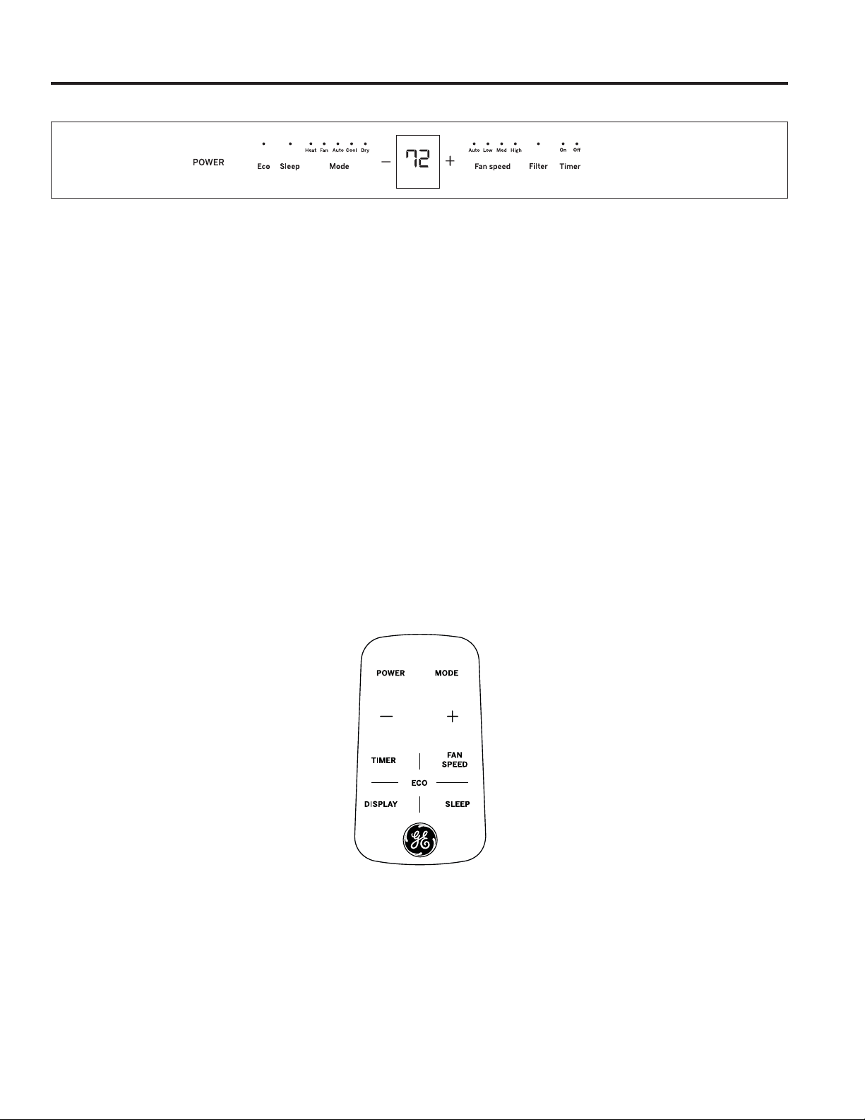
Using the Air Conditioner - Controls
USING THE AIR CONDITIONER
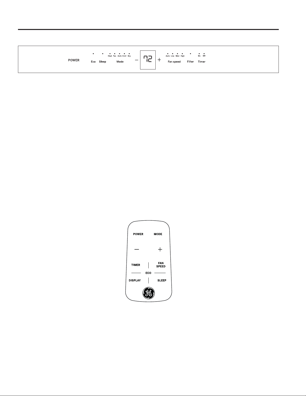
Air Conditioner Controls
ŶTo ensure proper operation, aim the remote control at
the signal receiver on the air conditioner.
ŶThe remote control signal has a range up to 21 feet.
ŶMake sure nothing is between the air conditioner and
the remote control that could block the signal.
ŶMake sure the battery is fresh and installed correctly—
see the Care and Cleaning section.
Appearance may vary.
Remote Control
Lights above the touch pads on the air conditioner
control panel indicate the selected settings.
1. POWER
Turns air conditioner on and off.
2. Display
Displays the temperature setting. Displays hours when
setting the timer.
3. Mode
8VHWRVHWCOOL, HEAT (on some models), DRY,
AUTO, or FAN modes. Indicator lights on the controls
will show the mode selected.
4. Temp Increase + / Decrease - Pads
8VHWRVHWWHPSHUDWXUHZKHQLQAUTO, COOL, DRY or
HEAT (on some models) mode.
5. Fan Speed
8VHWRVHWWKHIDQVSHHGDWLOW, MEDIUM, or HIGH.
Indicator lights will show the speed selected.
6. Timer
ON8VHWRVHWWKHDLUFRQGLWLRQHUWRDXWRPDWLFDOO\WXUQ
ON from 0.5 to 24 hours later.
OFF8VHWRDXWRPDWLFDOO\WXUQWKHDLUFRQGLWLRQHU
OFF from 0.5 to 24 hours later.
7. Filter
Monitors accumulated fan run time as a reminder to
clean the filter.
8. Eco
ON:8VHWRF\FOHWKHIDQRIIZKHQWKHFRPSUHVVRU
cycles off.
OFF:8VHWRUXQWKHIDQFRQWLQXRXVO\ZKHQLQFRROLQJ
or heating (on some models) mode.
9. Sleep
Allows room temperature to increase (Cool mode) or
decrease (Heat mode) during sleeping hours.
Temp/Timer

6 49-5000712 Rev. 1
Using the Air Conditioner - Features
USING THE AIR CONDITIONER
To Adjust Fan Speeds
Press the Fan Speed button to select the FAN Speed in
four steps - Auto, Low, Med, or High. Each time the button is
pressed, the fan speed mode is shifted.
For some models, the fan speed can not be adjusted under
HEAT mode. In DRY mode, the fan speed is controlled at low
automatically.
Sleep
Press the Sleep button to initiate the sleep mode. In this mode,
the selected temperature will increase (cooling) or decrease
KHDWLQJE\)&PLQXWHVDIWHUWKHPRGHLVVHOHFWHG
The temperature will then increase (cooling) or decrease
KHDWLQJE\DQRWKHU)&DIWHUDQDGGLWLRQDOPLQXWHV
This new temperature will be maintained for 7 hours before it
returns to the originally selected temperature. This ends the
Sleep mode and the unit will continue to operate as originally
programmed. The Sleep mode program can be cancelled at any
time during operation by pressing the Sleep button again.
Check Filter
Press the Filter button to initiate this feature. This feature is a
reminder to clean the air filter for more efficient operation.
The LED (light) will illuminate after 250 hours of operation. To
reset after cleaning the filter, press the Filter button and the
light will go off.
Eco - Energy Saver
Press the Eco button to initiate this feature. This feature is
available on COOL, DRY, AUTO, (only AUTO-COOLING and
AUTO-FAN) modes. The fan will continue to run for 3 minutes
after the compressor shuts off.
The fan then cycles on for 2 minutes at 10 minute intervals until
the room temperature is above the set temperature, at which
time the compressor turns back on and Cooling starts.
Timer: Auto Start / Stop
ŶWhen the unit is on or off, first press the Timer button, the
TIMER ON indicator light illuminates. It indicates the Auto
Start program is initiated.
ŶWhen the time of TIMER ON is displayed, press the Timer
button again, the TIMER OFF indicator light illuminates. It
indicates the Auto Stop program is initiated.
ŶPress or hold the + or – button to change the Auto time by 0.5
hour increments, up to 10 hours, then at 1 hour increments up
to 24 hours. The control will count down the time remaining
until start.
ŶThe selected time will register in 5 seconds, and the
system will automatically revert back to display the previous
temperature setting or room temperature when the unit is on.
(When the unit is off, there is no display.)
ŶTurning the unit ON or OFF at any time or adjusting the timer
VHWWLQJWRZLOOFDQFHOWKH$XWR6WDUW6WRSWLPHGSURJUDP
To Select the Operating Mode
To choose operating mode, press the Mode button. Each time
you press the button, a mode is selected in a sequence that
goes from AUTO, COOL, DRY, HEAT (on some models) and
FAN only. The indicator light above will be illuminated and
remain on once the mode is selected.
The unit will initiate the Energy Saver function under COOL,
DRY, AUTO (only AUTO-COOLING and AUTO-FAN) modes.
To Operate on Auto Feature:
ŶWhen you set the air conditioner in AUTO mode, it will
automatically select cooling, heating (on some models)or
fan only operation depending on what temperature you have
selected and the room temperature.
ŶThe air conditioner will control room temperature
automatically to the temperature set point.
ŶIn this mode, the fan speed cannot be adjusted, it starts
automatically at a speed according to the room temperature.
To Operate on Fan Only:
Ŷ8VHWKLVIXQFWLRQRQO\ZKHQFRROLQJLVQRWGHVLUHG<RXFDQ
choose any fan speed you prefer.
Ŷ'XULQJWKLVIXQFWLRQWKHGLVSOD\ZLOOVKRZWKHDFWXDOURRP
temperature, not the set temperature in the cooling mode.
Ŷ,Q)DQRQO\PRGHWKHWHPSHUDWXUHLVQRWDGMXVWDEOH
To Operate on Dry Mode:
Ŷ,QWKLVPRGHWKHDLUFRQGLWLRQHUZLOOJHQHUDOO\RSHUDWHLQ
the form of a dehumidifier. Since the conditioned space is a
closed or sealed area, some degree of cooling will continue.
Fahrenheit vs. Celsius
To change the temperature display from Fahrenheit to Celsius, press – and + together and hold for 5 seconds.
49-5000712 Rev. 1 7
Using the Air Conditioner - Features
USING THE AIR CONDITIONER
Additional Features
The “Cool” circuit has an automatic 3 minute delayed
start if the unit is turned off and on quickly. This prevents
overheating of the compressor and possible circuit
breaker tripping. The fan will continue to run during this
time.
There is a 2 second delay for the compressor to stop
when selecting FAN ONLY/HEAT. This is to cover the
possibility of having to roll through to select another
mode.
The control will maintain the set temperature within 1°F
between 62°F and 86°F in cool or heat mode (on some
models).
After a power outage, the unit will remember last setting
and return the unit to that setting when power is restore.
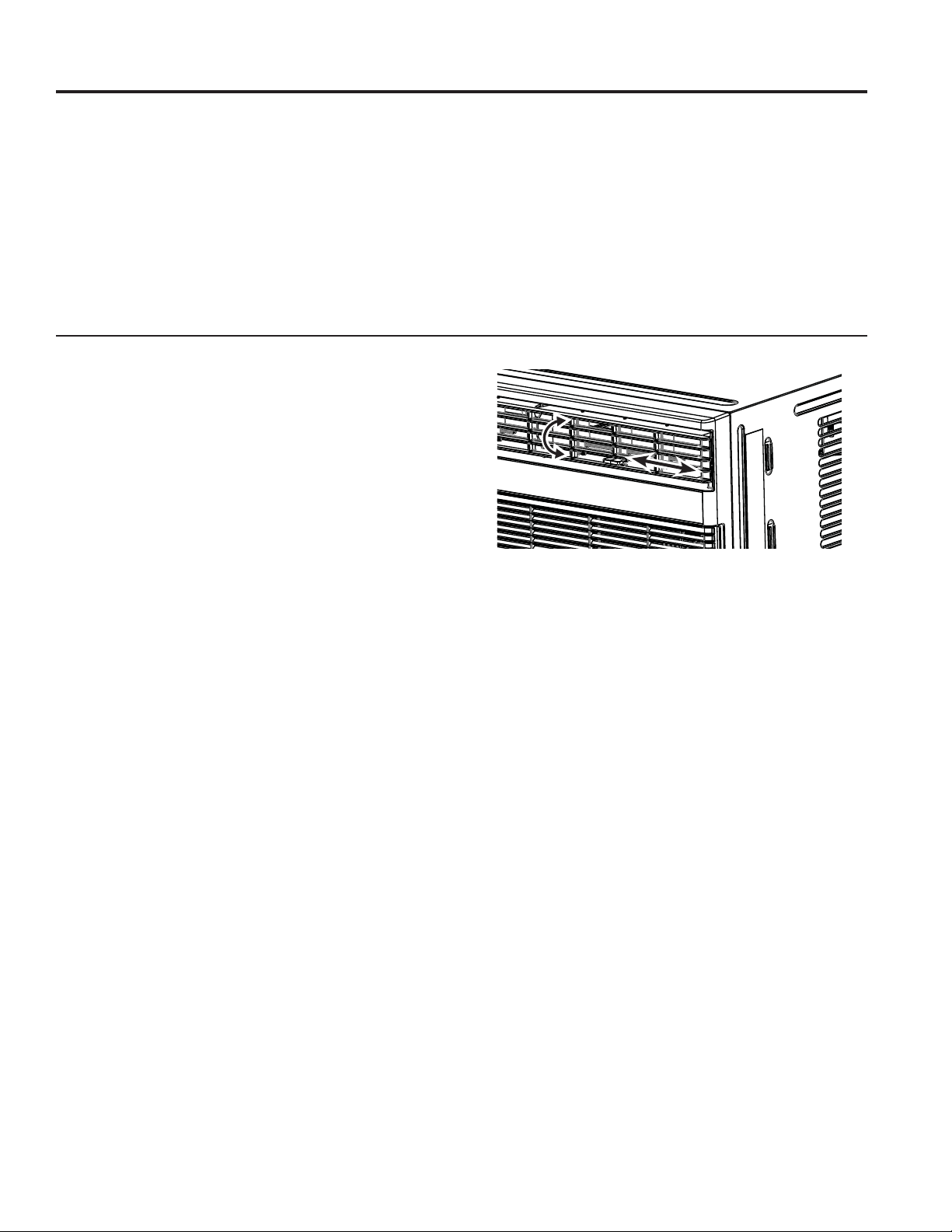
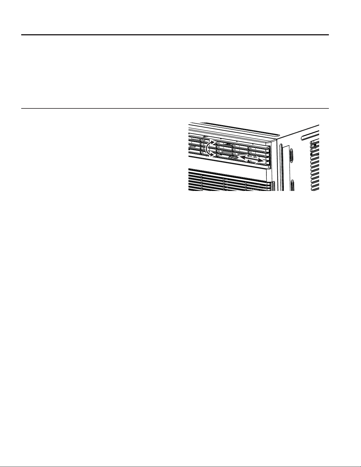
Air Direction
Air directional louvers control air flow direction.
The louvers will allow you to direct the air flow up or down
and left or right throughout the room as needed until the
GHVLUHGOHIWULJKWGLUHFWLRQLVREWDLQHG3LYRWKRUL]RQWDO
ORXYHUVXQWLOWKHGHVLUHGXSGRZQGLUHFWLRQLVREWDLQHG

8 49-5000712 Rev. 1
CARE AND CLEANING
Care and Cleaning
How to Insert the Batteries in the Remote Control
1. Remove the battery cover by sliding the locking tab to
the left and pulling the battery cover out of the remote.
2. Insert a new battery, making sure that the (+) and (-) of
the battery are installed correctly, (+) side up.
3. Reattach the cover by sliding it back into the remote.
NOTES:
• 8VH&59'&EDWWHU\'RQRWXVHUHFKDUJHDEOH
batteries.
• Remove the battery from the remote control if the
system is not going to be used for an extended period
of time.
Outdoor Coils
• The coils on the outdoor side of the air conditioner
should be checked regularly.
• If they are clogged with dirt or soot, they may need to
be professionally cleaned, a service available through
GE Appliances service or other service companies.
Front Grille Removal
The front grille can be removed for a more thorough cleaning.
To remove:
1. Grasp the sides of the front grille by the recessed
areas on each side and tilt forward.
2. Remove the filter by pulling forward and out.
3. Remove the two Phillips head screws located on the
upper corners of the grille.
4. Push inward on each side of the metal chassis cover
about 5” from the bottom. This will release the tabs
on the grille from the metal chassis cover. Pull the
bottom of the grille slightly forward while lifting the
grille upward.
5. Once the grille is released, gently raise it upward
to release the tabs from the top of the metal chassis
cover.
6. To release the multi-pin electrical connector from the
user interface, press both sides and gently pull apart.
Reverse the order to re-install the grille.
Air filter
To access the filter, grasp the front grille on both sides at
the recess and tilt forward. Remove the filter by lifting up
and out. Note the filter direction when re-installing.
Wash the filter using liquid dishwashing detergent and
warm water. Rinse the filter thoroughly. Gently shake
excess water from the filter.
Be sure the filter is thoroughly dry before replacing. Or,
instead of washing, you may vacuum the filter until clean.
NOTE: Never use hot water over 104°F (40°C) to clean
the air filter. Never attempt to operate the unit without the
air filter.
Energy Saving Note
In order to reach maximum energy saving and comfort, it
is recommended to use a cover to insulate the unit when
the unit is not in use. The recommended cover size for
the unit is 24.4” x 14.8” x 2.2” (W x H x D).
NOTE:8QSOXJWKHXQLWEHIRUHLQVWDOOLQJDFRYHU
Cabinet
• Be sure to unplug the air conditioner to prevent shock
or fire hazard. The cabinet and front may be dusted
with an oil-free cloth or washed with a cloth dampened
in a solution of warm water and mild liquid dishwashing
detergent. Rinse thoroughly with a damp cloth and
wipe dry.
• Never use harsh cleaners, wax, or polish on the
cabinet front.
• Be sure to wring excess water from the cloth before
wiping around the controls. Excess water in or around
the controls may cause damage to the air conditioner.
• Plug in the air conditioner.
49-5000712 Rev. 1 9
INSTALLATION INSTRUCTIONS
Installation Instructions
For more help, visit GEAppliances.com
BEFORE YOU BEGIN
Read these instructions completely and
carefully.
•
IMPORTANT – Save these
instructions for local inspector’s use.
•
IMPORTANT – Observe all
governing codes and ordinances.
• Note to Installer – Be sure to leave these
instructions with the consumer.
• Note to Consumer – Keep these instructions for
future reference.
• Skill level – Installation of this appliance requires
basic mechanical skills.
• Completion time – Approximately 1 hour
• We recommend that two people install this
product.
• Proper installation is the responsibility of the
installer.
• Product failure due to improper installation is not
covered under the Warranty.
<RX0867XVHSURSHULQVWDOODWLRQSURFHGXUHVDV
described in these instructions when installing this
air conditioner.
ELECTRICAL REQUIREMENTS
CAUTION
• Do not, under any circumstances, cut or remove
the third (ground) prong from the power cord.
• Do not change the plug on the power cord of this
air conditioner.
• Aluminum house wiring may present special
problems—consult a qualified electrician.
Power cord includes a current interrupter device. A
TEST and RESET button are provided on the plug
case. The device should be tested on a periodic
basis by first pressing the TEST button and then
the RESET button while plugged into the outlet.
If the TEST button does not trip or if the RESET
button will not stay engaged, discontinue use of
the air conditioner and contact a qualified service
technician.
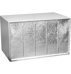
For Existing Wall Sleeves
Note that the air conditioner dimensions are: 24”
wide, 14” high, and 18” deep (without front). Install air
conditioner according to these Installation Instructions
to achieve the best performance. Save these
Installation Instructions for future reference.
NOTE: Do not use any screws other than those
specified here.
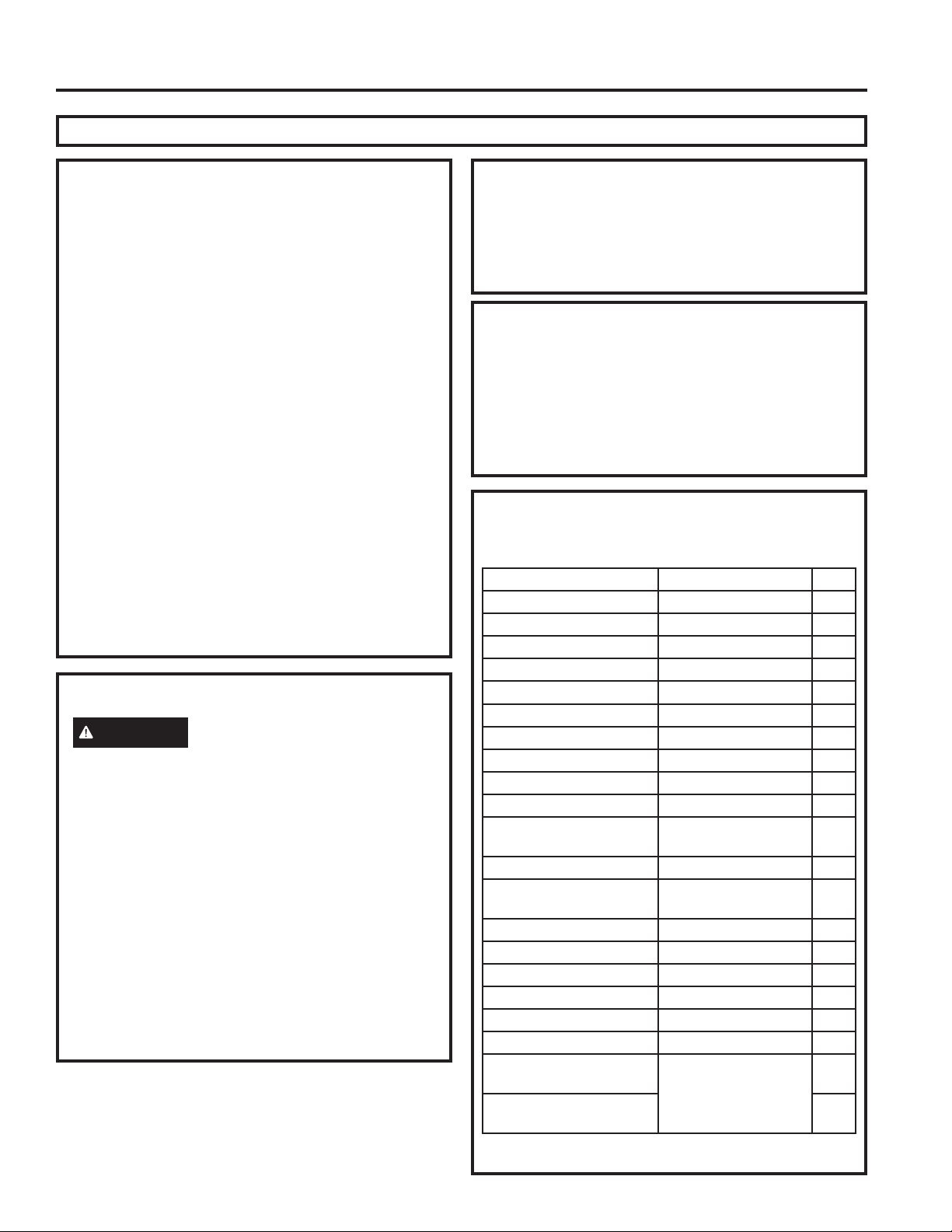
Parts Included
You may not need all parts in the kit. Discard unused
parts.
Name Spec. Qty
Tapered spacer Blocks 17” long 2
&HQWHULQJ6XSSRUW%ORFNV ´[´[´ 4
Plastic Divider ´[´[´ 2
Stuffer Seal ´[´[´ 1
Seal ´[´[´ 3
Seal ´[´[´ 2
Seal ´[´[´ 3
Seal ´[´[´ 2
Seal 2
Trim Frame (side legs) 2
Trim Frame (top & bottom
legs)
2
Ground Wire (green) 1
Toothed Washer for
grounding screw
2
Grounding Screw 1
Grille (Plastic) 1
Grille (Aluminum) 1
Nuts (Plastic) 4
Screw Washer 4
Screw 4
Security Brackets for a
24” Wall Sleeve
(in separate packetS
with 4 mounting
screws)
2
Security Brackets for a
26” Wall Sleeve
2
IMPORTANT NOTE
For optimal energy efficiency and performance,
we recommend using the RAB24 Wall Sleeve and the
supplied stamped aluminum outdoor grille or
the RAB26A with the RAG13 stamped aluminum
outdoor grille.
10 49-5000712 Rev. 1
How to Install In Pre-Existing Wall Sleeve
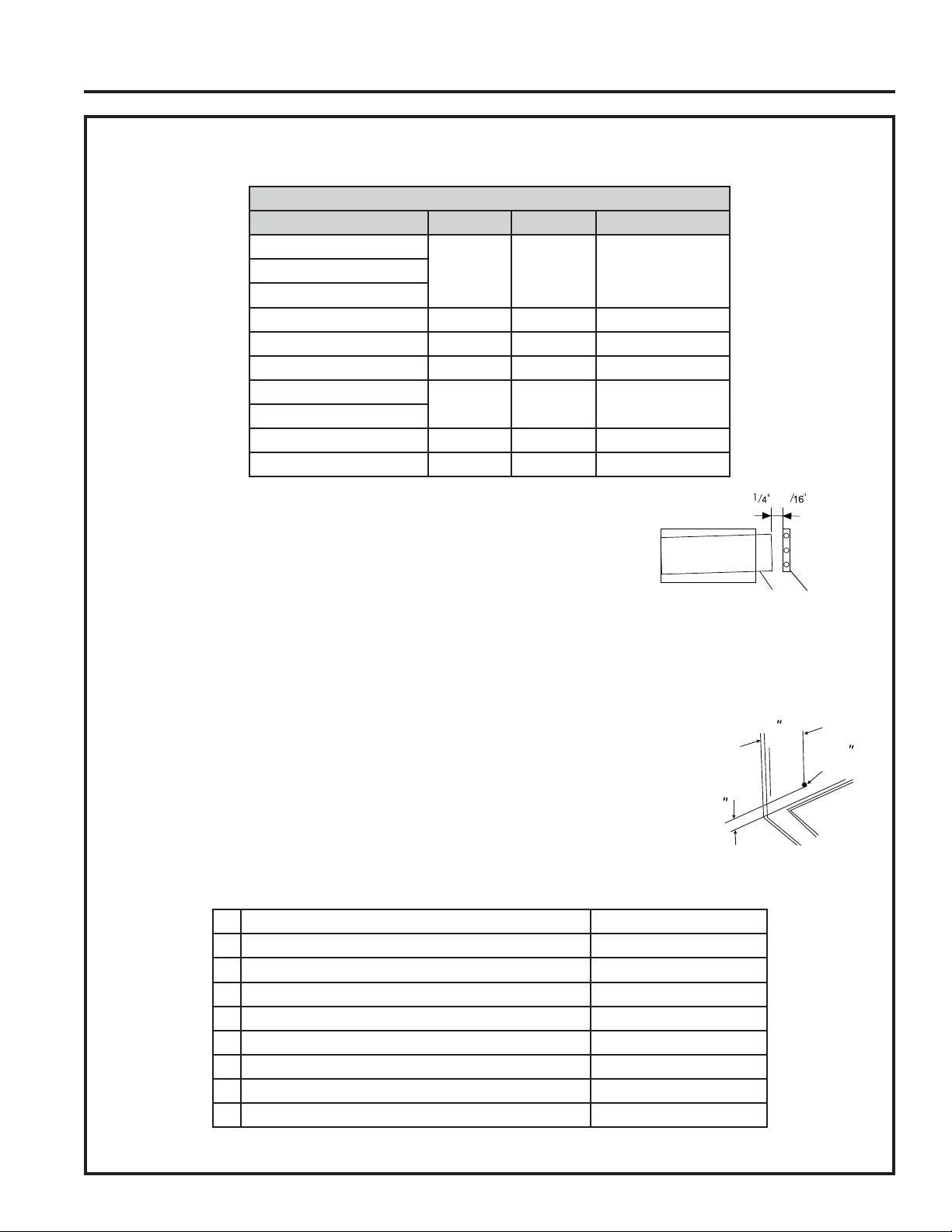
1. Identify the wall-sleeve brand for your installation, from the chart below.
Wall Sleeve Dimensions (inches)
Width Height Depth
White-Westinghouse
RU
Frigidaire
Carrier (52F Series)
GE/Hotpoint 26
Whirlpool RU
Fedders/Emerson 27 RU
Sears/Kenmore
Carrier (51S Series)
Emerson/Fedders 15
Friedrich 27
NOTE: All wall sleeves used to mount the new air conditioner must
be in sound structural condition and have a rear grille that securely
attaches to sleeve, or rear flange that serves as a stop for the air
conditioner.
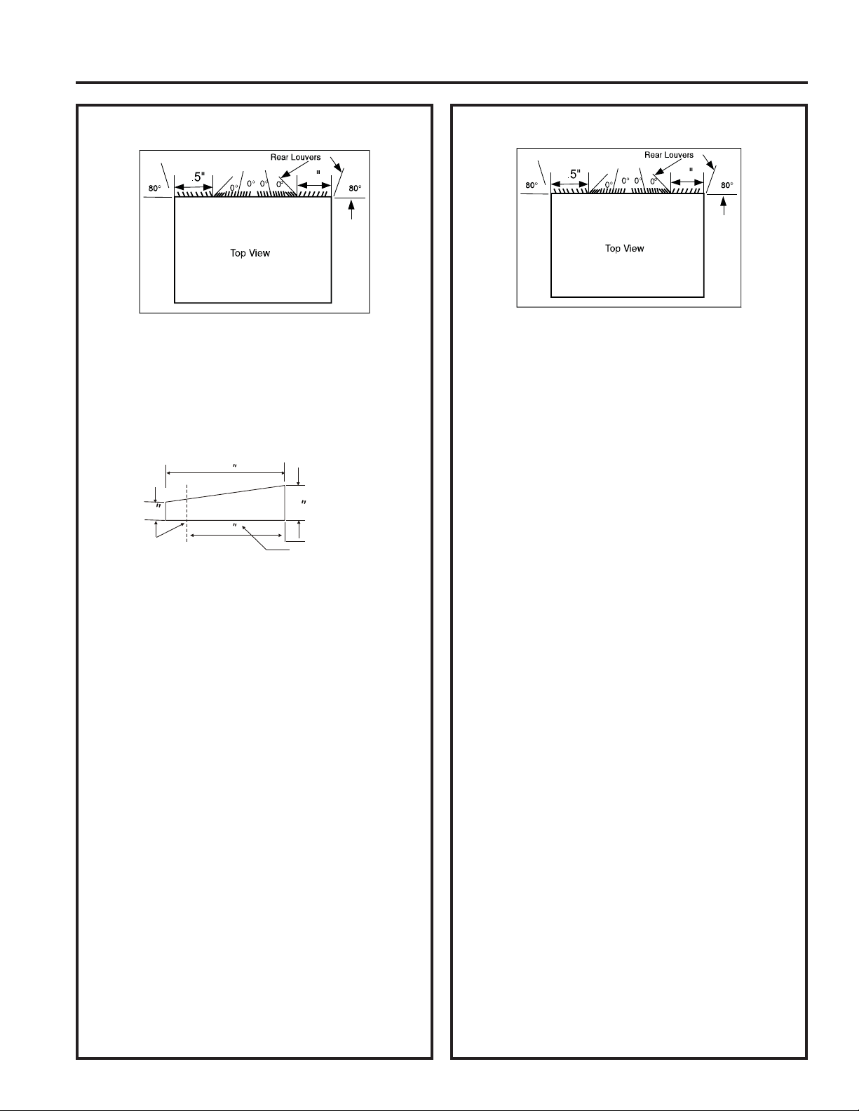
IMPORTANT::KHQLQVWDOODWLRQLVFRPSOHWHUHSODFHPHQWXQLW0867
have a rearward slope as shown.
2. Remove old air conditioner from wall sleeve and prepare wall sleeve as follows:
Ŷ&OHDQLQWHULRUGRQRWGLVWXUEVHDOV
Ŷ:DOOVOHHYHPXVWEHVHFXUHO\IDVWHQHGLQZDOOEHIRUHLQVWDOOLQJDLUFRQGLWLRQHU. Drive more nails or screws
through sleeve, into wall, if needed.
Ŷ5HSDLUSDLQWLIQHHGHG
3. ,IQRWSUHH[LVWLQJGULOOD´KROHWRDWWDFKWKHVXSSOLHGJURXQGLQJZLUHWRWKH
left side of the wall sleeve (see approximate hole location dimensions in the
LOOXVWUDWLRQEHORZ8VHWKHWRRWKHGZDVKHUDQGSRLQWHGVFUHZWRDWWDFKRQHHQG
of the supplied green striped ground wire to the inside of the wall sleeve. The
toothed washer must be between the eyelet of the wire and the wall sleeve. BE
CAREFUL TO NOT OVERTIGHTEN THE SCREW. Pull loose end of ground
wire out front of sleeve, and temporarily bend it down and around lower edge of
sleeve. This ground wire will later be attached to frame of air conditioner once it is installed.
4. Prepare the wall sleeve for installation of the new unit per the following brand instructions.
1 Emerson 15” Deep
2 Fedders ´'HHS
3 Fedders or Friedrich ´'HHS
4 *(+RWSRLQW ´'HHS
5 Sears or Carrier (51S Series) ´'HHS
6 Whirlpool ´'HHS
7 Whirlpool 23” Deep
8 :KLWH:HVWLQJKRXVH)ULJLGDLUH&DUULHU)6HULHV ´´'HHS
9 :KLWH:HVWLQJKRXVH)ULJLGDLUH 22” Deep
5. Identify your wall sleeve type and follow the instructions for that type in the following pages.
1
3
Max.
1/8
Hole
REAR
Wall Sleeve
UNIT
LEVEL
FRONT
to
3
INSTALLATION INSTRUCTIONS
Installation Instructions
49-5000712 Rev. 1 11
Installation Instructions
INSTALLATION INSTRUCTIONS
Emerson (15” Deep)
4
4
3
8
3
8
1. Remove existing rear grille as shown on page 9
of this manual and replace with provided louvered
rear panel.
NOTE: You may need to drill holes in flange of
existing sleeve to match new rear grille.
2.$WWDFK´[´[´ORQJVHDOLQWKHFHQWHUDW
the top of the sleeve. Remove the backing paper
and press into position.
3.$WWDFKWKH´[´[´ORQJVHDOVWRWKHOHIW
and right sides of the sleeve.
4.&XW´[´[´VHDOVWR´ORQJDQGDWWDFK
them to the vertical sections of the
rear grille.
5.$WWDFK´[´[´FHQWHULQJVXSSRUW
blocks, one on each side wall. Place in center of
side wall with the tapered end facing the opening.
6. Gently slide unit into sleeve.
7. Before sliding all-the-way back, remove the second
screw from front on the left side of unit.
8. Remove the plastic washer from the screw.
9. Screw and attach the other end of the ground wire
to the unit. Make sure that the toothed washer is
against the cabinet.
10. Slide the unit completely to the rear to ensure a
good seal, making sure the ground wire does not
become tangled.
11. If you have difficulty with mounting the grill to the
sleeve, follow the instructions for direct mounting
on page 15.
12. Seal and frame the unit as described on
page 16.
IMPORTANT - BEFORE YOU BEGIN
Ŷ7KLVXQLW¶VSHUIRUPDQFHFKDUDFWHULVWLFVUHVXOWIURP
having two rear air intakes.
Ŷ,WLVYHU\LPSRUWDQWWKDWWKHVHLQVWUXFWLRQVDUH
followed so the unit can operate at maximum
efficiency.
Ŷ,IWKLVLVDQH[LVWLQJVOHHYHDQGWKHUHLVDQH[LVWLQJ
rear grille, it may need to be replaced by one that
has been shipped with the unit in the accessory
kit. If the new rear grille is too small for the rear
sleeve opening, use the black plastic grille. Insure
it is secured in place using the included screws,
washers and grommets.
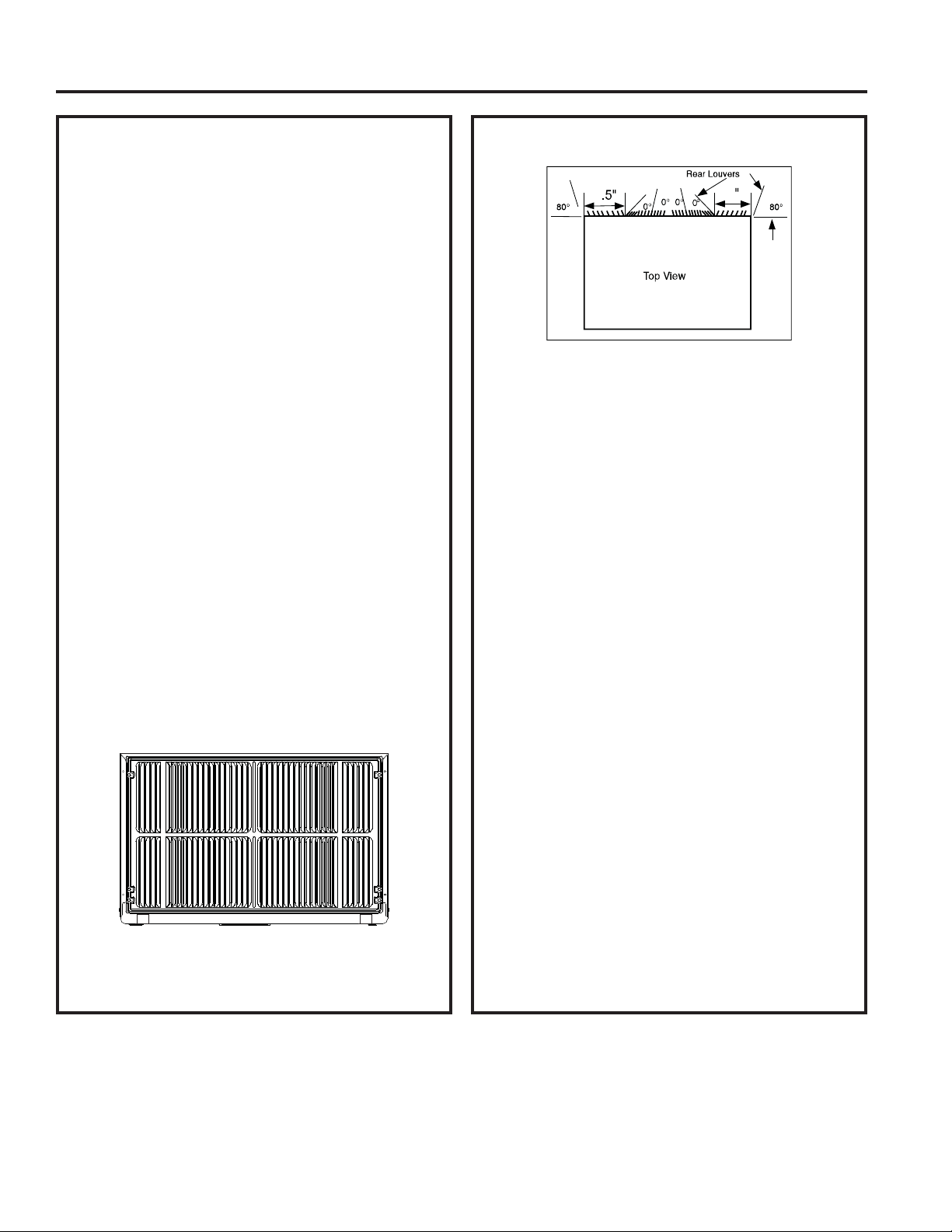
FOR INCREASED EFFICIENCY, UTILIZE THE
PROVIDED LOUVERED REAR PANEL
Installation of new grille provided with unit.
1. Remove the existing grille. (Exception: GE 26”.)
2. Place the grille, included with the new air
conditioner, towards the rear of the sleeve.
3. Mark through the hole positions.
4.'ULOOWKURXJKWKHVOHHYHVIODQJHVZLWKD´GULOOELW
5. Attach the new grille with self-threading screws and
washers.
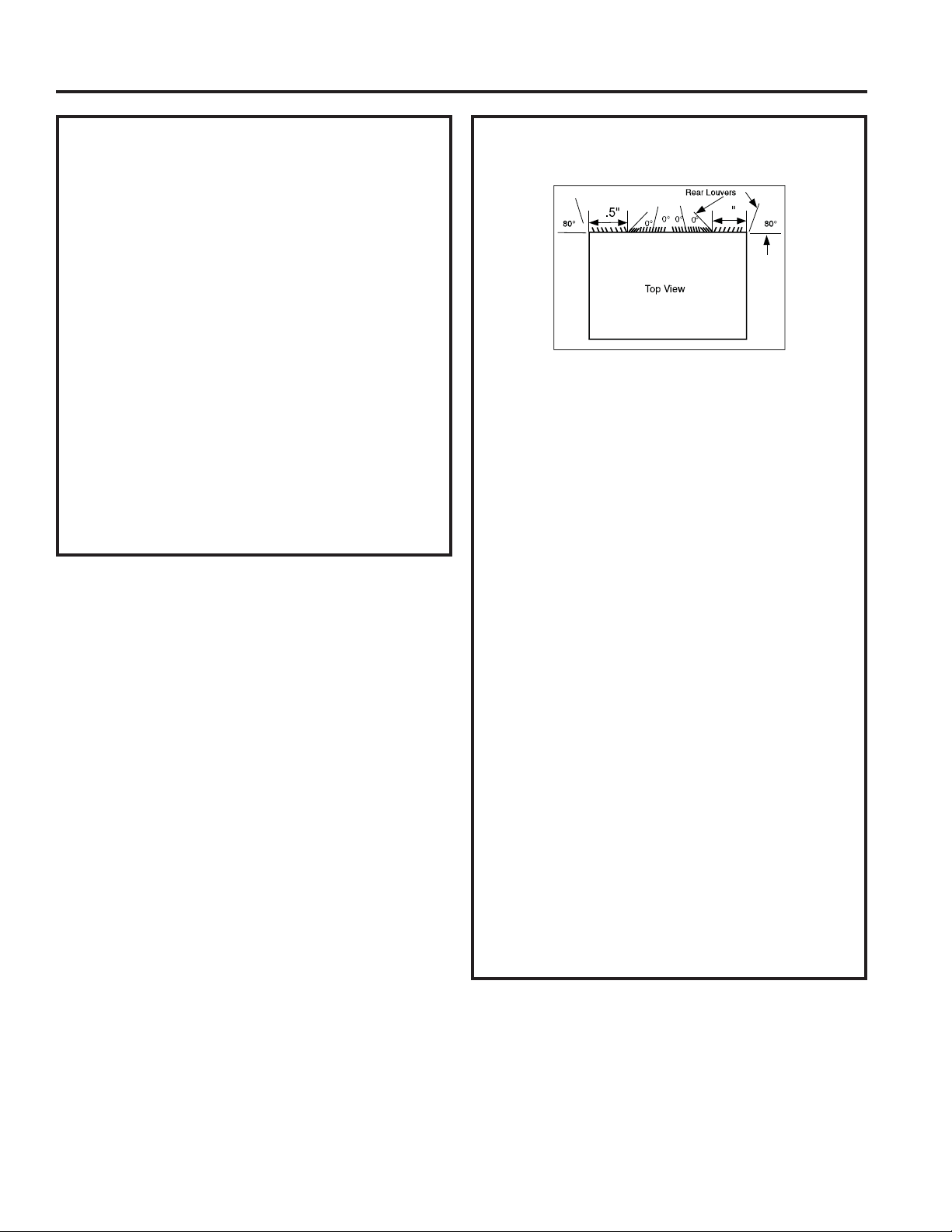
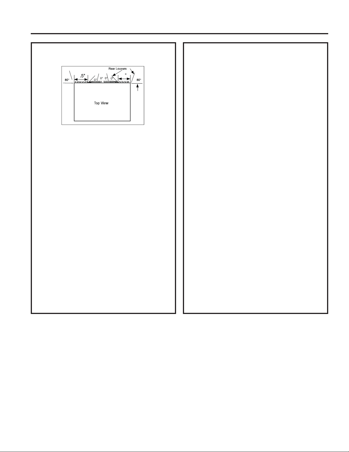
6.,WLV9(5<,03257$17WKDWWKHJULOOHLVSODFHG
exactly as shown below.
7. Most decorative exterior grilles may be left in place
as long as the proper interior air direction grille is
installed.
12 49-5000712 Rev. 1
INSTALLATION INSTRUCTIONS
Installation Instructions
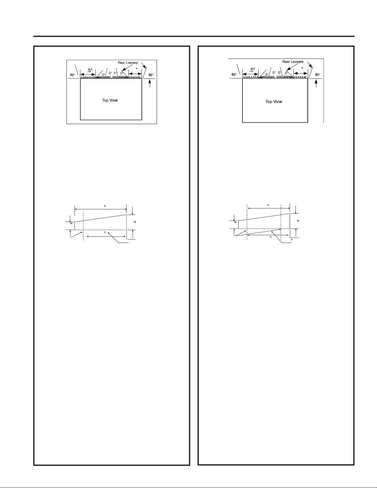
Fedders (19-3/4” Deep)
1. Remove existing rear grille as shown on page 9
of this manual and replace with provided louvered
rear panel.
NOTE: You may need to drill holes in flange of
existing sleeve to match new rear grille.
2.$WWDFK´[´[´FHQWHULQJVXSSRUW
blocks, one on each side wall. Place in center of
side wall with the tapered end facing the opening.
3. Cut (2) 17” tapered spacer blocks as shown below
into two pieces.
4. The 4” section is placed in front of the rib on base
with the tapered end facing the back of the sleeve.
The remaining portion will be placed behind the rib
again sloping toward
the rear of the sleeve. This helps induce a
rearward slope on the unit.
5.$WWDFK´[´[´ORQJVHDOLQWKHFHQWHUDW
the top of the sleeve. Remove the backing paper
and press into position.
6.$WWDFK´[´[´VHDOVWRWKHOHIWDQGULJKW
sides of the sleeve.
7.&XW´[´[´VHDOVWR´ORQJDQGDWWDFK
them to the vertical sections of the rear grille.
8. Gently slide unit into sleeve.
9. Before sliding all-the-way back, remove the second
screw from front on left side of unit.
10. Remove the plastic washer from the screw.
11. Screw and attach the other end of the ground wire
to the unit. Make sure that the toothed washer is
against the cabinet.
12. Slide the unit completely to the rear to ensure a
good seal, making sure the ground wire does not
become tangled.
13. If you have difficulty with mounting the grill to the
sleeve, follow the instructions for direct mounting
on page 15.
14. Seal and frame the unit as described on page 16.
4
4
3
8
3
8
Cut Here
3
/
4
17
Tapered Spacer Block
1
Protection Paper
Backing
4
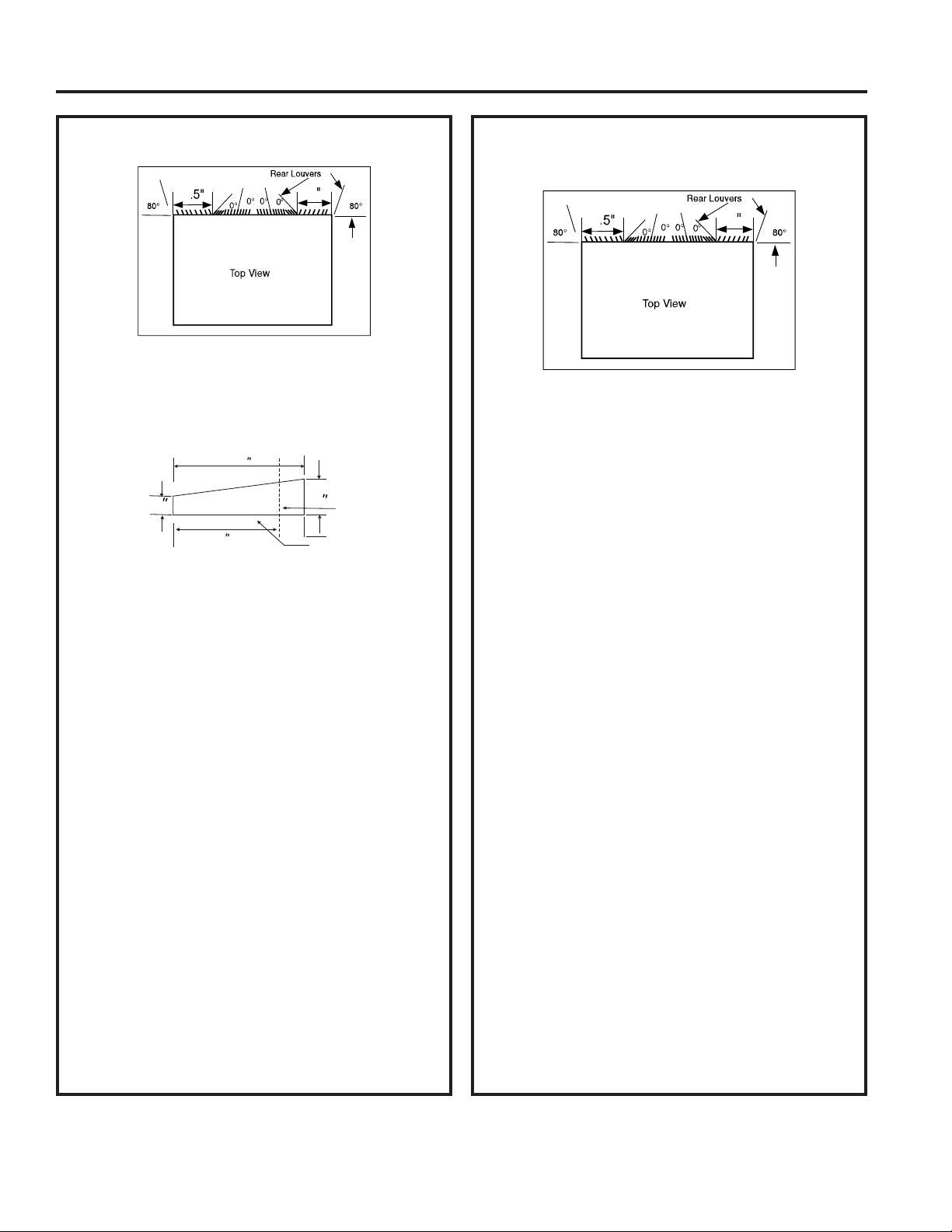
Fedders or Friedrich (16-3/4” Deep)
1. Remove existing rear grille as shown on page 9
of this manual and replace with provided louvered
rear panel.
NOTE: You may need to drill holes in flange of
existing sleeve to match new rear grille.
2.$WWDFK´[´[´FHQWHULQJVXSSRUW
blocks, one on each side wall. Place in center of
side wall with the tapered end facing the opening.
3. Cut (2) 17” tapered spacer blocks as shown below
into three pieces.
4.7KH´VHFWLRQLVSODFHGLQIURQWRIWKHULERQ
base with the tapered end facing the back of the
VOHHYH&XWWKHUHPDLQLQJSRUWLRQWR´DQG
placed behind the rib again sloping toward the rear
of the sleeve. This helps induce a rearward slope
on the unit.
5.$WWDFK´[´[´ORQJVHDOLQWKHFHQWHUDW
the top of the sleeve. Remove the backing paper
and press into position.
6.$WWDFK´[´[´VHDOVWRWKHOHIWDQGULJKW
sides of the sleeve.
7.&XW´[´[´VHDOVWR´ORQJDQGDWWDFK
them to the vertical sections of the rear grille.
8. Gently slide unit into sleeve.
9. Before sliding all-the-way back, remove the second
screw from front on left side of unit.
10. Remove the plastic washer from the screw.
11. Screw and attach the other end of the ground wire
to the unit. Make sure that the toothed washer is
against the cabinet.
12. Slide the unit completely to the rear to ensure a
good seal, making sure the ground wire does not
become tangled.
13. If you have difficulty with mounting the grill to the
sleeve, follow the instructions for direct mounting
on page 15.
14. Seal and frame the unit as described on page 16.
4
4
3
8
3
8
Cut Here
3
/
4
17
Tapered Spacer Block
1
Protection Paper
Backing
12-1/2
2-1/2
49-5000712 Rev. 1 13
Installation Instructions
INSTALLATION INSTRUCTIONS
Sears or Carrier 51S Series
(18-5/8” Deep)
4
4
3
8
3
8
1. Remove existing rear grille as shown on page 9
of this manual and replace with provided louvered
rear panel.
NOTE: You may need to drill holes in flange of
existing sleeve to match new rear grille.
2. Install (2) tapered spacer blocks to the floor of the
sleeve. This helps induce a rearward slope on the
unit.
3.,QVWDOOZLWKWKHWDSHUHGHQG´IURPWKHEDFNRI
the sleeve. This helps induce a rearward slope on
the unit.
4.$WWDFK´[´[´ORQJVHDOLQWKHFHQWHUDW
the top of the sleeve. Remove the backing paper
and press into position.
5.$WWDFK´[´[´VHDOVWRWKHOHIWDQGULJKW
sides of the sleeve.
6.&XW´[´[´VHDOVWR´ORQJDQGDWWDFK
them to the vertical sections of the rear grille.
7. Center unit and gently slide unit into sleeve.
8. Before sliding all-the-way back, remove the second
screw from front on left side of unit.
9. Remove the plastic washer from the screw.
10. Screw and attach the other end of the ground wire
to the unit. Make sure that the toothed washer is
against the cabinet.
11. Slide the unit completely to the rear to ensure a
good seal, making sure the ground wire does not
become tangled.
12. If you have difficulty with mounting the grill to the
sleeve, follow the instructions for direct mounting
on page 15.
13. Seal and frame the unit as described on page 16.
GE/Hotpoint (16-7/8” Deep)
4
4
3
8
3
8
1. Retain existing rear grille.
2.8VLQJQHHGOHQRVHSOLHUVFKDQJHWKHRXWGRRUJULOOH
directional louvers per the illustration above.
3. Cut (2) 17” tapered spacer blocks as shown below
into two pieces.
4.,QVWDOO´VHFWLRQZLWKWKHWDSHUHGHQG´
from the back of the sleeve. This helps induce a
rearward slope on the unit.
5.$WWDFK´[´[´ORQJVHDOLQWKHFHQWHUDW
the top of the sleeve. Remove the backing paper
and press into position.
6.$WWDFK´[´[´VHDOVWRWKHOHIWDQGULJKW
sides of the sleeve.
7.&XW´[´[´VHDOVWR´ORQJDQGDWWDFK
them to the vertical sections of the rear grille.
8. Center unit and gently slide unit into sleeve.
9. Before sliding all-the-way back, remove the second
screw from front on left side of unit.
10. Remove the plastic washer from the screw.
11. Screw and attach the other end of the ground wire
to the unit. Make sure that the toothed washer is
against the cabinet.
12. Slide the unit completely to the rear to ensure a
good seal, making sure the ground wire does not
become tangled.
13. If you have difficulty with mounting the grill to the
sleeve, follow the instructions for direct mounting
on page 15.
14. Seal and frame the unit as described on page 16.
3
/
4
17
Tapered Spacer Block
1
Protection Paper
Backing
Cut Here
13
14 49-5000712 Rev. 1
INSTALLATION INSTRUCTIONS
Installation Instructions
Whirlpool (17-1/8” Deep)
4
4
3
8
3
8
1. Remove existing rear grille as shown on page 9
of this manual and replace with provided louvered
rear panel.
NOTE: You may need to drill holes in flange of
existing sleeve to match new rear grille.
2. Cut (2) 17” tapered spacer blocks as shown below
into two pieces.
3. Install 13” section to the floor of the sleeve. This
helps induce a rearward slope on the unit.
4.$WWDFK´[´[´ORQJVHDOLQWKHFHQWHUDW
the top of the sleeve. Remove the backing paper
and press into position.
5.$WWDFK´[´[´VHDOVWRWKHOHIWDQGULJKW
sides of the sleeve.
6.&XW´[´[´VHDOVWR´ORQJDQGDWWDFK
them to the vertical sections of the rear grille.
7. Center unit and gently slide unit into sleeve.
8. Before sliding all-the-way back, remove the second
screw from front on left side of unit.
9. Remove the plastic washer from the screw.
10. Screw and attach the other end of the ground wire
to the unit. Make sure that the toothed washer is
against the cabinet.
11. Slide the unit completely to the rear to ensure a
good seal, making sure the ground wire does not
become tangled.
12. If you have difficulty with mounting the grill to the
sleeve, follow the instructions for direct mounting
on page 15.
13. Seal and frame the unit as described on page 16.
3
/
4
17
Tapered Spacer Block
1
Protection Paper
Backing
Cut Here
13
Whirlpool (23” Deep)
4
4
3
8
3
8
1. Remove existing rear grille as shown on page 9
of this manual and replace with provided louvered
rear panel.
NOTE: You may need to drill holes in flange of
existing sleeve to match new rear grille.
Because of the increased unit depth, first try dry
fitting using the method described below:
2.3ODFH´[´[´VHDOVDJDLQVWHDFKVLGH
3. Gently slide unit in and check if amount extending
from the sleeve is sufficient once the trim frame is
attached.
4. If position is correct, remove unit and proceed to
the next step. If not, go to step 9.
5.$WWDFK´[´[´ORQJVHDOLQWKHFHQWHU
at the top of the sleeve. Remove the backing paper
and press into position.
6.$WWDFK´[´[´VHDOVWRWKHOHIWDQG
right sides of the sleeve.
7.&XW´[´[´VHDOVWR´ORQJDQGDWWDFK
them to the vertical sections of the grille.
8. Attach the tapered spacer blocks to the floor of the
sleeve. Now go to step 15.
Use these next steps if the unit requires extra
extension into the room:
9.$WWDFK´[´[´ORQJVHDORYHUWKHVROLG
vertical portion of the rear grille.
10.$WWDFK´[´[´IRDPEORFNV
with the slot overlapping the seal above.
11. Install the divider into the slots of the foam blocks.
You may need to trim the length to size.
12. Repeat steps 9-11 for the other vertical portion of
the grille.
13.$WWDFK´[´[´VHDOVDORQJWKHVLGHV
of the sleeve again making sure all seals are
flush.
14.&XWWKH´[´[´VHDOWRILWWKHWRSRIWKH
sleeve. The pieces must be fitted flush to the
edge of the divider.
49-5000712 Rev. 1 15
Installation Instructions
INSTALLATION INSTRUCTIONS
White-Westinghouse/Frigidaire/Carrier
52F Series (16” + 17-1/2” Deep)
4
4
3
8
3
8
1. Remove existing rear grille as shown on page
9 of this manual and replace with provided
louvered rear panel.
NOTE: You may need to drill holes in flange of
existing sleeve to match new rear grille.
2.$WWDFK´[´[´ORQJVHDOLQWKHFHQWHU
at the top of the sleeve. Remove the backing
paper and press into position.
3.$WWDFK´[´[´VHDOVWRWKHOHIWDQG
right sides of the sleeve.
4.$WWDFK´[´[´ORQJVHDOVYHUWLFDOO\´
from the left side of the sleeve and 4” from the
right side of the sleeve.
5. Center unit and gently slide unit into sleeve.
6. Before sliding all-the-way back, remove the
second screw from front on left side of unit.
7. Remove the plastic washer from the screw.
8. Screw and attach the other end of the ground
wire to the unit. Make sure that the toothed
washer is against the cabinet.
9. Slide the unit completely to the rear to ensure
a good seal, making sure the ground wire does
not become tangled.
10. If you have difficulty with mounting the grill to
the sleeve, follow the instructions for direct
mounting on page 15.
11. Seal and frame the unit as described on
page 16.
Whirlpool (23” Deep) (cont)
15. Center unit and gently slide unit into sleeve.
16. Before sliding all-the-way back, remove the first
screw from front on left side of unit.
17. Remove the plastic washer from the screw.
18. Screw and attach the other end of the ground wire
to the unit. Make sure that the toothed washer is
against the cabinet.
19. Slide the unit completely to the rear to ensure a
good seal, making sure the ground wire does not
become tangled.
20. If you have difficulty with mounting the grill to the
sleeve, follow the instructions for direct mounting
on page 15.
21. Seal and frame the unit as described on page 16.
16 49-5000712 Rev. 1
INSTALLATION INSTRUCTIONS
Installation Instructions
White-Westinghouse or Frigidaire
(22” Deep) (cont)
8.$WWDFK´[´[´ORQJVHDORYHUWKHVROLGYHUWLFDO
portion of the rear grille.
9.
$WWDFK´[´[´IRDPEORFNVZLWK
the slot overlapping the seal above.
10.
Install the divider into the slots of the foam blocks.
You may need to trim the length to size.
11.
Repeat steps 8-10 for the other vertical shown
portion of the grille.
12.
$WWDFK´[´[´VHDOVDORQJWKHVLGHVRI
the sleeve again making sure all seals are flush.
13.
&XWWKH´[´[´VHDOWRILWWKHWRSRIWKH
sleeve. The pieces must be fitted flush to the edge
of the divider.
14.
Center unit and gently slide unit into sleeve.
15. Before sliding all-the-way back, remove the first
screw from the front on left side of the unit.
16.
Remove the plastic washer from the screw.
17. Screw and attach the other end of the ground wire
to the unit. Make sure that the toothed washer is
against the cabinet.
18.
Slide the unit completely to the rear to ensure a
good seal, making sure the ground wire does not
become tangled.
19.
If you have difficulty with mounting the grill to the
sleeve, follow the instructions for direct mounting
on page 15.
20. Seal and frame the unit as described on page 16.
White-Westinghouse or Frigidaire
(22” Deep)
1. Remove existing rear grille as shown on page 9
of this manual and replace with provided louvered
rear panel.
NOTE: You may need to drill holes in flange of existing
sleeve to match new rear grille.
Because of the increased unit depth, first try dry
fitting using the method described below:
2.
3ODFH´[´[´VHDOVDJDLQVWHDFKVLGH
3. Gently slide unit in and check if amount extending
from the sleeve is sufficient once the trim frame is
attached.
4.
If position is correct, remove unit and proceed to the
next step. If not, go to step 8.
5.
$WWDFK´[´[´ORQJVHDOWRWKHOHIWVLGH
and right side of the sleeve.
6.
&XW´[´[´VHDOWR´ORQJDQGDWWDFK
them vertically to the rear grill 4.5” from the left side
of the sleeve and 4” from the right side of the sleeve.
7.
$WWDFK´[´[´ORQJVHDOLQWKHFHQWHUDW
the top of the sleeve. Remove the backing paper and
press into position. Proceed to step 14.
Use these next steps if the unit requires extra
extension into the room.
4
4
3
8
3
8
49-5000712 Rev. 1 17
INSTALLATION INSTRUCTIONS
Installation Instructions
Direct Unit Mounting:
The previous directions are the preferable way to mount the new rear grille. The units performance is slightly
better and the possibility of drafts is reduced. As a last resort, direct mounting of the grille to the unit can be
considered.
NOTE: The grille must be installed prior to inserting the unit into the sleeve.
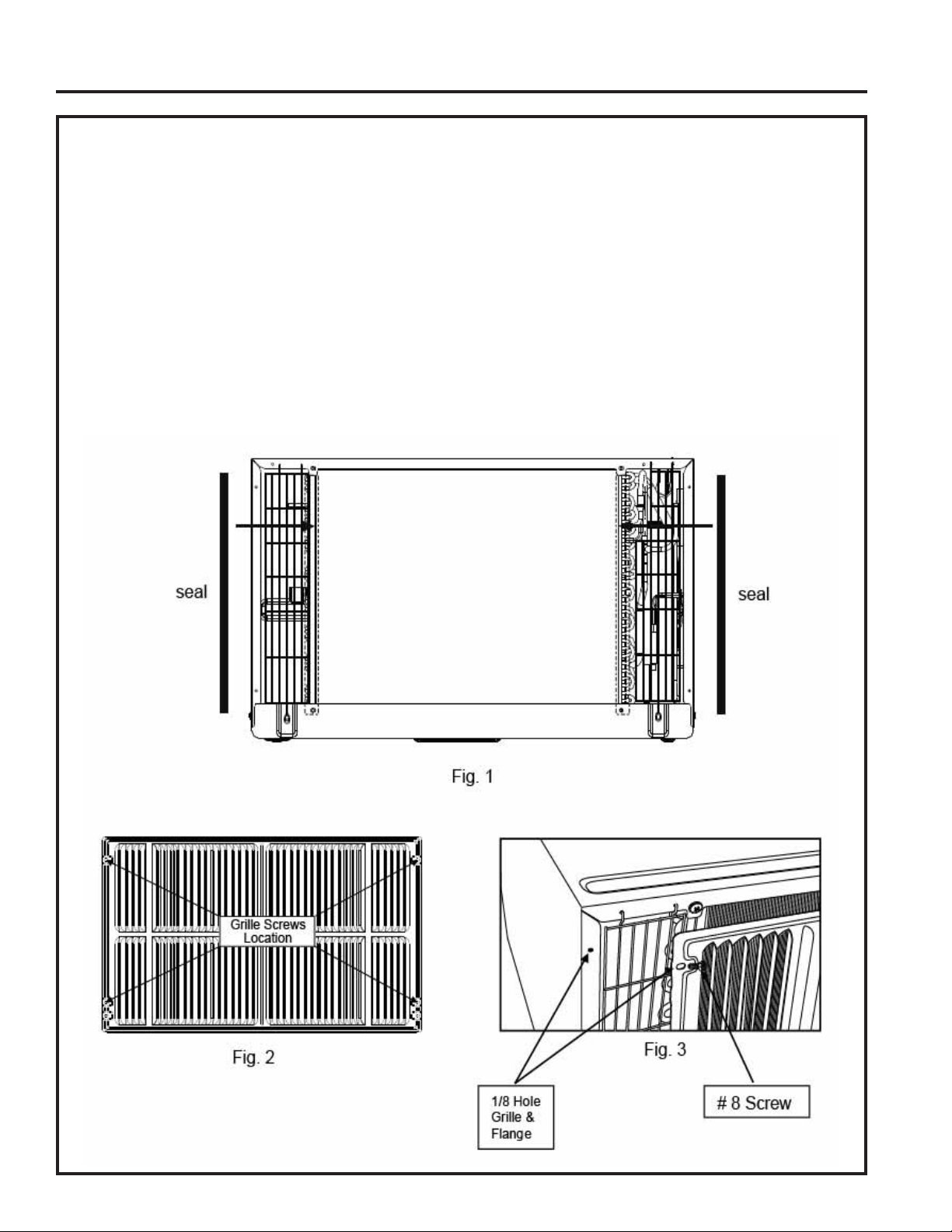
1.$WWDFKWKHVHDOSLHFHV´[´[´DVVKRZQLQWKHLOOXVWUDWLRQ
2. Position the grille over the rear of the unit making sure that:
a. The double set of screw holes are at the bottom.
b. The fins of the grille are pointed away from the unit.
3. Align the top of the grille with the top of the unit. The overhang on each side should be equal.
4.,IWKHXQLWKDVQRWEHHQSUHGULOOHGVRPHPRGHOVFDUHIXOO\GULOO´KROHVWKURXJKWKHJULOOHDQGLQWRWKH
VLGHIODQJHRIWKHXQLWDSSUR[LPDWHO\´WR´IURPWKHWRSDQGERWWRPDVVKRZQ
5. Install 4 #8 self-tapping screws to affix the grille to the unit.
6. Insert the unit into the sleeve.
18 49-5000712 Rev. 1
Installation Instructions
INSTALLATION INSTRUCTIONS
Trim Kit Installation Instructions
Ŷ,QVWDOOWKH´[´[´ORQJVWXIIHUVHDO
between the wall sleeve and the unit. A flat-bladed
screwdriver or putty knife is recommended.
ŶAssemble the trim frame by inserting the top and
bottom pieces into side pieces and snapping into
place.
ŶPull the cord through the trim frame and slide the
trim over the unit until flush with the wall or wall
sleeve.
Assemble Trim
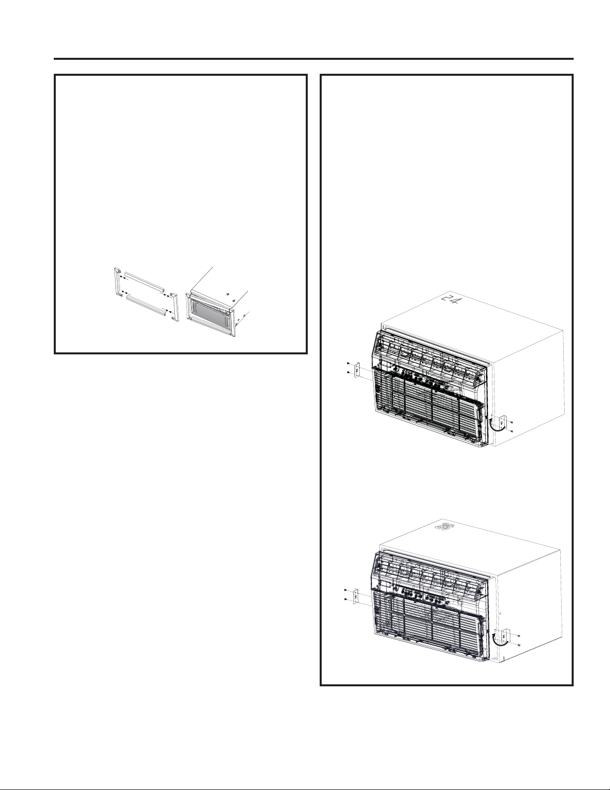
Security Brackets Installation
(It is important to install these brackets to prevent
the chassis from being pushed into the room
from the outside.)
Ŷ0HDVXUHWKHZLGWKRIWKHLQVWDOOHGZDOOVOHHYHDQG
choose the appropriate security bracket (24” or 26”)
designed for that sleeve.
ŶThe brackets must be installed so the flanges are
hooked behind the inside flanges of the wall sleeve.
8VLQJWKHVFUHZVSURYLGHGDWWDFKWKHEUDFNHWVRQ
the sides of the chassis.
For 24” sleeves, pull the unit out slightly, hook the
short flange of the 24” bracket behind the sleeve
inside edge and secure to the unit with the two screws
provided. Repeat on the opposite side. Push the unit
all the way back into the case.
For 26” sleeves, hook the short flange of the 26”
bracket behind the sleeve inside edge and secure to
the unit with the the two screws provided. Repeat on
the opposite side.
Hook inside
sleeve edge
and secure
to unit
Hook inside
sleeve edge
and secure
to unit
Hook inside
sleeve edge
and secure
to unit
Hook inside
sleeve edge
and secure
to unit

49-5000712 Rev. 1 19
Troubleshooting Tips... Before you call for service
TROUBLESHOOTING TIPS
Problem Solution
Air conditioner does
not start
Wall plug disconnected. Push plug firmly into wall outlet.
House fuse blown or circuit breaker tripped. Replace fuse with time delay type or
reset circuit breaker.
Plug current device tripped. Press the RESET button.
Power is OFF. Turn power ON.
Air from the unit does
not feel cold enough
Room temperature below 62°F (17°C). Cooling may not occur until room temperature
rises above 62°F (17°C).
Temperature sensor behind air filter may be touching cold coil. Keep it from the cold
coil.
Set to a lower temperature.
Compressor stopped when changing modes. Wait for 3 minutes after set to the COOL
mode.
Air conditioner cooling,
but room is too warm.
Ice is forming on
cooling coil behind
decorative front.
Outdoor temperature below 64°F (18°C). To defrost the coil, set FAN ONLY mode.
Air filter may be dirty. Clean the filter. Refer to Care and Cleaning section. To defrost,
set to FAN ONLY mode.
Thermostat set to cold for night-time cooling. To defrost the coil, set to FAN ONLY
mode. Then, set temperature to a higher setting.
Dirty air filter, or the air is restricted. Clean the air filter. Refer to Care and Cleaning
section.
Temperature is set too high. Set the temperature to a lower setting.
Air directional louvers positioned improperly. Position louvers for better air distribution.
Front of unit is blocked by drapes, blinds, furniture, etc, which restricts air distribution.
Clear blockage in front of unit.
Doors, windows, registers, etc, may be open. Close doors, windows, registers.
8QLWUHFHQWO\WXUQHGRQLQKRWURRP$OORZDGGLWLRQDOWLPHWRUHPRYH³VWRUHGKHDW´IURP
walls, ceiling, floor, and furniture.
Air conditioner turns
on and off rapidly
Dirty air filter, the air is restricted. Clean air filter.
Outside temperature extremely hot. Set FAN speed to a higher setting to cool outdoor
cooling coil.
Noise when unit is
cooling
Air movement sound. This is normal. If too loud, set to a slower FAN setting.
Improper installation. Refer to installation instructions or check with installer.
Water dripping INSIDE
when unit is cooling
Improper installation. Tilt air conditioner slightly to the outside to allow water drainage.
Refer to installation instructions, and check with installer.
Water dripping
OUTSIDE when unit is
cooling
8QLWUHPRYLQJODUJHTXDQWLW\RIPRLVWXUHIURPKXPLGURRP7KLVLVQRUPDOGXULQJ
excessively humid days.
Room too cold Set temperature to low. Increase set temperature.
Error code “AS” in the
display
5RRPWHPSHUDWXUHVHQVRUHUURU8QSOXJWKHXQLWDQGSOXJLWEDFNLQ,IHUURUUHSHDWV
call for service. NOTE: In Fan only mode, it will display “LO” or “HI”.
Error code “HS” in the
display
(OHFWULFKHDWLQJVHQVRUHUURU8QSOXJWKHXQLWDQGSOXJLWEDFNLQ,IHUURUUHSHDWVFDOO
for service.
Error code “•” in the
display
(YDSRUDWRUWHPSHUDWXUHVHQVRUHUURU8QSOXJWKHXQLWDQGSOXJLWEDFNLQ,IHUURU
repeats, call for service.

20 49-5000712 Rev. 1
Notes
49-5000712 Rev. 1 21
GE Appliances Air Conditioner Limited Warranty
Staple your receipt here. Proof of the original purchase date
is needed to obtain service under the warranty.
LIMITED WARRANTY
Ŷ6HUYLFHWULSVWR\RXUKRPHWRWHDFK\RXKRZWRXVHWKH
product.
Ŷ,PSURSHULQVWDOODWLRQGHOLYHU\RUPDLQWHQDQFH,I\RX
have an installation problem, or if the air conditioner
is of improper cooling capacity for the intended use,
contact your dealer or installer. You are responsible for
providing adequate electrical connecting facilities.
Ŷ)DLOXUHRIWKHSURGXFWUHVXOWLQJIURPPRGLILFDWLRQV
to the product or due to unreasonable use including
failure to provide reasonable and necessary
maintenance.
Ŷ,QFRPPHUFLDOORFDWLRQVODERUQHFHVVDU\WRPRYHWKH
unit to a location where it is accessible for service by
an individual technician.
Ŷ5HSODFHPHQWRIKRXVHIXVHVRUUHVHWWLQJRIFLUFXLW
breakers.
Ŷ)DLOXUHGXHWRFRUURVLRQRQPRGHOVQRWFRUURVLRQ
protected.
Ŷ'DPDJHWRWKHSURGXFWFDXVHGE\LPSURSHUSRZHU
supply voltage, accident, fire, floods or acts of God.
Ŷ,QFLGHQWDORUFRQVHTXHQWLDOGDPDJHFDXVHGE\
possible defects with this air conditioner.
Ŷ'DPDJHFDXVHGDIWHUGHOLYHU\
What GE Appliances Will Not Cover:
This limited warranty is extended to the original purchaser and any succeeding owner for products purchased
IRUKRPHXVHZLWKLQWKH86$,IWKHSURGXFWLVORFDWHGLQDQDUHDZKHUHVHUYLFHE\D*($SSOLDQFHV$XWKRUL]HG
Servicer is not available, you may be responsible for a trip charge or you may be required to bring the product
to an Authorized GE Service location for service. In Alaska, the limited warranty excludes the cost of shipping
or service calls to your home.
Some states do not allow the exclusion or limitation of incidental or consequential damages. This limited
warranty gives you specific legal rights, and you may also have other rights which vary from state to state.
To know what your legal rights are, consult your local or state consumer affairs office or your state’s Attorney
General.
Warrantor: GE Appliances, a Haier company
Louisville, KY 40225
All warranty service must be provided by our Factory Service Centers, or an authorized Customer Care
®
technician.
To schedule service, visit us on-line at GEAppliances.com/service, or call 800.GE.CARES (800.432.2737). Have
serial number and model number available when calling for service.
EXCLUSION OF IMPLIED WARRANTIES—Your sole and exclusive remedy is product repair as provided
in this Limited Warranty. Any implied warranties, including the implied warranties of merchantability or
fitness for a particular purpose, are limited to two years or the shortest period allowed by law.
For The Period Of: GE Appliances Will Replace:
Two Years
From the date of the
original purchase
Any part of the air conditioner which fails due to a defect in materials or workmanship.
During this limited two-year warranty, GE Appliances will also provide, free of charge, all
labor and related service to replace the defective part.

22 49-5000712 Rev. 1
Printed in China
Consumer Support
GE Appliances Website
Have a question or need assistance with your appliance? Try the GE Appliances Website 24 hours a day, any day
of the year! You can also shop for more great GE Appliances products and take advantage of all our on-line support
VHUYLFHVGHVLJQHGIRU\RXUFRQYHQLHQFH,QWKH86GEAppliances.com
Register Your Appliance
Register your new appliance on-line at your convenience! Timely product registration will allow for enhanced
communication and prompt service under the terms of your warranty, should the need arise. You may also mail in
WKHSUHSULQWHGUHJLVWUDWLRQFDUGLQFOXGHGLQWKHSDFNLQJPDWHULDO,QWKH86GEAppliances.com/register
Schedule Service
Expert GE Appliances repair service is only one step away from your door. Get on-line and schedule your service at
\RXUFRQYHQLHQFHDQ\GD\RIWKH\HDU,QWKH86GEAppliances.com/service or call 800.432.2737 during normal
business hours.
Extended Warranties
Purchase a GE Appliances extended warranty and learn about special discounts that are available while your
warranty is still in effect. You can purchase it on-line anytime. GE Appliances Services will still be there after your
ZDUUDQW\H[SLUHV,QWKH86GEAppliances.com/extended-warranty or call 800.626.2224 during normal
business hours.
CONSUMER SUPPORT
Parts and Accessories
Individuals qualified to service their own appliances can have parts or accessories sent directly to their homes
9,6$0DVWHU&DUGDQG'LVFRYHUFDUGVDUHDFFHSWHG2UGHURQOLQHWRGD\KRXUVHYHU\GD\
,QWKH86GEApplianceparts.com or by phone at 877.959.8688 during normal business hours.
Instructions contained in this manual cover procedures to be performed by any user. Other servicing
generally should be referred to qualified service personnel. Caution must be exercised, since improper
servicing may cause unsafe operation.
Contact Us
If you are not satisfied with the service you receive from GE Appliances, contact us on our Website with all the
details including your phone number, or write to:
,QWKH86*HQHUDO0DQDJHU&XVWRPHU5HODWLRQV_*($SSOLDQFHV$SSOLDQFH3DUN_/RXLVYLOOH.<
GEAppliances.com/contact

Transcrivez les numéros de modèle
et de série ici :
# de modèle _____________
# de série _______________
Vous trouverez l’étiquette
signalétique sur le côté du
climatiseur.
GE est une marque déposée de General Electric Company. Fabriqué sous licence de marque.
Le climatiseur
Modèles 24” à Travers le mur
49-5000712 Rev. 1 08-22 GEA
INFORMATION DE SÉCURITÉ ...3
UTILISANT LE CLIMATISEUR ..4
ENTRETIEN ET NETTOYAGE ....7
INSTRUCTIONS
D’INSTALLATION
...............8
CONSEILS DE DÉPANNAGE ....18
SOUTIEN AU CONSOMMATEUR
Garantie limitée ......................19
Soutien au consommateur ............ 20
MANUEL D’UTILISATION
ET INSTRUCTIONS
D’INSTALLATION
Rafraîchissement uniquement
AKCQ08ACJ
AKCQ10ACJ
AKCQ10DCJ
AKCQ12ACJ
AKCQ12DCJ
AKCQ14DCJ
Réchauffement/Rafraîchessment
AKEQ10DCJ
AKEQ12DCJ
AKEQ14DCJ

2 49-5000712 Rev. 1
NOUS VOUS REMERCIONS D’ACCUEILLIR GE APPLIANCES CHEZ VOUS
Que vous ayez grandi avec GE Appliances ou qu’il s’agisse de votre première acquisition, nous
sommes heureux de vous accueillir dans notre famille.
Nous sommes fiers du savoir-faire, de l’innovation et de l’esthétique qui composent chaque appareil
GE Appliances, et nous pensons que vous le serez aussi. Dans cette optique, nous vous rappelons
que l’enregistrement de votre électroménager vous assure la communication de renseignements
importants sur le produit et la garantie lorsque vous en avez besoin.
Enregistrez votre électroménager GE en ligne dès maintenant. Des sites Web et des numéros de
téléphone utiles figurent dans la section Soutien au consommateur de ce manuel d’utilisation.
49-5000712 Rev. 1 3
Pour votre sécurité, vous devez suivre les instructions de ce manuel pour
réduire les risques d’incendie, d’explosion, de choc électrique, de dommage à
la propriété, de blessure ou de décès.
Ŷ1¶XWLOLVH]FHWDSSDUHLOTXHSRXUVRQXVDJHSUpYXWHOTXH
décrit dans le Manuel de l’utilisateur.
Ŷ9RXVGHYH]ELHQPRQWHUFHFRQGLWLRQQHXUFRQIRUPpPHQW
aux Instructions de montage, avant de l’utiliser.
Ŷ1HGpEUDQFKH]MDPDLVYRWUHFRQGLWLRQQHXUHQWLUDQWVXU
le cordon d’alimentation. Saisissez fermement la fiche et
sortez-la droit de sa prise.
Ŷ5HPSODFH]LPPpGLDWHPHQWWRXWFRUGRQG¶DOLPHQWDWLRQ
abîmé ou endommagé. Un cordon d’alimentation électrique
endommagé ne doit pas être réparé mais plutôt remplacé
par un autre cordon d’alimentation obtenu du fabricant.
N’utilisez pas un cordon d’alimentation qui montre des
fissures ou des signes d’abrasion sur sa longueur ou encore
près de la prise ou du connecteur.
ŶeWHLJQH]HWGpEUDQFKH]YRWUHFOLPDWLVHXUDYDQWGHSURFpGHU
à une réparation ou un nettoyage.
Ŷ3RXUYRWUHVpFXULWp«QHUDQJH]MDPDLVRXQ¶XWLOLVH]MDPDLV
des matériaux combustibles, de l’essence ou d’autres
vapeurs ou liquides inflammables à proximité de cet
appareil ou de tout autre appareil électroménager.
Ŷ6LODSULVHpOHFWULTXHQ¶HVWSDVFRPSDWLEOHDYHFODILFKH
du cordon électrique, il faut faire remplacer la prise par un
électricien agréé.
Ŷ*($SSOLDQFHVQREULQGDVRSRUWHVREUHQLQJ~QVHUYLFLR
técnico de componentes del sistema sellado (es decir:
piezas que contengan refrigerante) del acondicionador de
aire.
Ŷ(OVHUYLFLRWpFQLFRGHOUHVWRGHORVFRPSRQHQWHV6Ï/2
podrá ser completado por un técnico calificado.
Ŷ(VWHHOHFWURGRPpVWLFRQRGHEHUiVHUXVDGRSRUSHUVRQDV
(incluyendo niños) con capacidades físicas, sensoriales
o mentales reducidas o con falta de experiencia y
conocimiento, a menos que cuenten con supervisión o
instrucción con relación al uso de este electrodoméstico por
parte de una persona responsable de su seguridad.
Ŷ6HGHEHUiVXSHUYLVDUDORVQLxRVDILQGHDVHJXUDUTXHQR
VHMXHJXHFRQHOHOHFWURGRPpVWLFR
Ŷ1RXWLOLFHVXDFRQGLFLRQDGRUGHDLUHHQXQDKDELWDFLyQ
K~PHGDWDOFRPRXQEDxRRODYDGHUR
Ŷ(OHOHFWURGRPpVWLFRVHGHEHUiJXDUGDUDILQGHHYLWDUTXH
se produzcan daños mecánicos.
COMMENT BRANCHER L’ÉLECTRICITÉ
1HFRXSH]RXQ¶HQOHYH]MDPDLVODEURFKHGHPLVHjODWHUUH
(la troisième broche de la fiche) du cordon d’alimentation.
3RXUYRWUHVpFXULWpSHUVRQQHOOHFHWDSSDUHLOGRLWrWUHELHQPLV
à la terre.
N’utilisez PAS une fiche d’adaptation avec cet
électroménager.
/HFRUGRQG¶DOLPHQWDWLRQGHFHWDSSDUHLOHVWPXQLG¶XQHILFKH
triphasée (mise à la terre) qui correspond à une prise murale
normale triphasée, pour réduire le danger de secousse
électrique.
/HFRUGRQG¶DOLPHQWDWLRQSHXWFRPSUHQGUHXQPpFDQLVPH
d’interruption de courant. Un bouton d’essai et de remise
HQPDUFKHHVWIRXUQLVXUOHERvWLHUGHODSULVH9RXVGHYH]
essayer le mécanisme périodiquement en appuyant d’abord
sur le bouton TEST (essai) puis sur le bouton RESET
(remise en marche). Si le bouton TEST ne bascule pas ou
si le bouton RESET ne reste pas enfoncé, cessez d’utiliser
votre conditionneur d’air et appelez un technicien de service
qualifié.
Faites vérifier la prise murale et le circuit électrique par un
électricien qualifié pour vous assurer que la prise est bien à la
terre.
Si vous avez une prise biphasée, vous êtes personnellement
responsable et obligé de la faire remplacer par une prise
murale triphasée bien mise à la terre.
9RXVGHYH]WRXMRXUVEUDQFKHUOHFRQGLWLRQQHXUGDQVVDSURSUH
prise électrique, d’un voltage qui correspond à la plaque
signalétique.
Cela vous permettra d’obtenir le meilleur rendement et
empêchera la surcharge des circuits électriques de la maison,
qui risque d’occasionner un danger d’incendie.
Consultez les Instructions de montage, section des
Exigences électriques, pour les exigences de branchements
électriques particuliers.
INFORMATION DE SÉCURITÉ
INFORMATION DE SÉCURITÉ IMPORTANTES
LISEZ TOUTES LES DIRECTIVES AVANT D'UTILISER L'APPAREIL
LIRE ET CONSERVER CES INSTRUCTIONS
AVERTISSEMENT
UTILISATION DE RALLONGES RISQUE D’INCENDIE.
Peut occasionner des blessures graves ou la mort.
Ŷ1(3$6XWLOLVHUGHUDOORQJHDYHFFHFRQGLWLRQQHXU
d’air.
Ŷ1(3$6XWLOLVHUGHSDUDVXUWHQVHXURXG¶DGDSWDWHXUj
prises multiples avec ce conditionneur d’air.
AVERTISSEMENT
4 49-5000712 Rev. 1
INFORMATION DE SÉCURITÉ
INFORMATION DE SÉCURITÉ IMPORTANTES
LISEZ TOUTES LES DIRECTIVES AVANT D'UTILISER L'APPAREIL
LIRE ET CONSERVER CES INSTRUCTIONS
Déclaration de conformité de la FCC :
&HWDSSDUHLOHVWFRQIRUPHjODSDUWLHGHVUqJOHVGHOD)&&6RQIRQFWLRQQHPHQWHVWDVVXMHWWLDX[GHX[
conditions suivantes :
&HWDSSDUHLOQHGRLWSDVSURYRTXHUG¶LQWHUIpUHQFHVSUpMXGLFLDEOHV
2. Cet appareil doit accepter toute interférence reçue, y compris les interférences pouvant entraîner un mauvais
fonctionnement.
Peligro de Quemaduras con Químicos. Mantenga las baterías alejadas de los niños.
Ŷ(VWHSURGXFWRFRQWLHQHXQDEDWHUtDGHOLWLRFRQFHOGDV
tipo botón/ moneda. Si una batería de litio con celdas tipo
botón/ moneda nueva o usada es tragada o ingresa en el
cuerpo, podrá ocasionar quemaduras internas graves y
producir la muerte en un tiempo tan corto como 2 horas.
Siempre asegure completamente el compartimiento de la
batería. Si el compartimiento de la batería no se cierra de
IRUPDVHJXUDGHMHGHXVDUHOSURGXFWRUHWLUHODVEDWHUtDV\
PDQWHQJDHOPLVPRDOHMDGRGHORVQLxRV
Ŷ6LFUHHTXHODVEDWHUtDVIXHURQWUDJDGDVRFRORFDGDVGHQWUR
de cualquier parte del cuerpo, busque atención médica de
inmediato.
Ŷ/DVFHOGDVVHGHEHUiQGHVFDUWDUGHIRUPDDGHFXDGDOR
FXDOLQFOX\HPDQWHQHUODVPLVPDVDOHMDGDVGHORVQLxRV
Ŷ,QFOXVRODVFHOGDVXVDGDVSRGUiQRFDVLRQDUOHVLRQHV
Riesgo de incendio o Explosión Esta unidad contiene un refrigerante inflamable. Se
deberán seguir las precauciones adicionales de seguridad.
Ŷ1RXVHPHGLRVSDUDDFHOHUDUHOSURFHVRGHGHVFRQJHODFLyQ
o para limpiar que no sean aquellos recomendados por el
fabricante.
Ŷ(VWHHOHFWURGRPpVWLFRVHGHEHUiJXDUGDUHQXQDVDOD
donde no haya fuentes de ignición en funcionamiento
FRQVWDQWHSRUHMHPSOROODPDVDELHUWDVXQ
electrodoméstico a gas en funcionamiento o un calefactor
eléctrico en funcionamiento.
Ŷ1RSHUIRUHQLTXHPHHOWXERUHIULJHUDQWH7HQJDSUHVHQWH
que los refrigerantes no deben tener olor.
Ŷ0DQWHQJDODVDEHUWXUDVGHODYHQWLODFLyQOLEUHVGH
obstrucciones.
Ŷ$OPRYHULQVWDODU\RSHUDUHOHOHFWURGRPpVWLFRVHGHEHUi
tener cuidado para evitar dañar la tubería del refrigerante.
Ŷ1RUHDOLFHSHUIRUDFLRQHVHQODXQLGDG
Ŷ(OPDQWHQLPLHQWRODOLPSLH]D\HOVHUYLFLRWpFQLFRVyOR
deberán ser realizados por técnicos adecuadamente
entrenados y calificados en el uso de refrigerantes
inflamables.
Ŷ*($SSOLDQFHVQREULQGDVRSRUWHVREUHQLQJ~QVHUYLFLR
técnico de componentes del sistema sellado (es decir: piezas
que contengan refrigerante) del acondicionador de aire.
Ŷ'HVFDUWHHOHOHFWURGRPpVWLFRGHDFXHUGRFRQODV
5HJXODFLRQHV)HGHUDOHV\/RFDOHV/RVUHIULJHUDQWHV
inflamables requieren procedimientos de descarte
específicos. Comuníquese con las autoridades locales
para descartar su acondicionador de aire de forma
ambientalmente segura.
WARNING
WARNING
3DUDREWHQHULQIRUPDFLyQVREUHHOUHFLFODMHGHHOHFWURGRPpVWLFRVYLVLWHGEAppliances.com/recycling.
49-5000712 Rev. 1 5
Commandes du climatiseur
Ŷ3RXUVRQERQIRQFWLRQQHPHQWGLULJH]ODWpOpFRPPDQGHYHUV
le récepteur de signal sur le climatiseur
.
Ŷ/HVLJQDOGHODWpOpFRPPDQGHDXQHSRUWpHGHMXVTX¶j
pieds.
Ŷ$VVXUH]YRXVTX¶DXFXQREMHWQHEORTXHOHVLJQDOHQWUHOH
climatiseur et la télécommandel.
Ŷ$VVXUH]YRXVTXHODFKDUJHGHODSLOHHVWVXIILVDQWHHWTXH
FHWWHGHUQLqUHHVWFRUUHFWHPHQWLQVWDOOpH²9R\H]ODVHFWLRQ
Entretien et nettoyage.
/¶DVSHFWSHXWYDULHU
Télécommande
/HVWpPRLQVOXPLQHX[DXGHVVXVGHVWRXFKHVVXUOHSDQQHDXGH
commande du climatiseur indiquent les réglages choisis.
Utilisant le climatiseur - Commandes
UTILISANT LE CLIMATISEUR
1. POWER (Mise sous/Hors tension)
Allume ou éteint le climatiseur.
2. Display (Afficher)
Affiche le réglage de température. Affiche les heures lors du
réglage de la minuterie.
3. Mode
3HUPHWGHVpOHFWLRQQHUOHVPRGHV&22/FOLPDWLVDWLRQ+($7
FKDXIIDJHFHUWDLQVPRGqOHV'5<GpVKXPLGLILFDWLRQ$872
RX)$1YHQWLODWHXU/HVWpPRLQVOXPLQHX[GHVFRPPDQGHV
indiqueront le mode sélectionné.
4.
Touches d’augmentation (+) / Diminution (-) de la
température
3HUPHWGHUpJOHUODWHPSpUDWXUHGDQVOHVPRGHV$XWR&RRO
'U\RX+HDWFHUWDLQVPRGqOHV
5. Fan Speed (Vitesse du ventilateur)
3HUPHWGHUpJOHUODYLWHVVHGXYHQWLODWHXUj/2:EDV
0('PR\HQ+,*+KDXW%2267SOHLQHSXLVVDQFHRX
2))DUUrW/HVWpPRLQVOXPLQHX[LQGLTXHURQWODYLWHVVH
sélectionnée.
6. Timer (Minuterie)
ON 0DUFKH3RXUUpJOHUODPLVHHQPDUFKHGXYHQWLODWHXU
automatiquement dans un délai de 0,5 à 24 heures.
OFF$UUrW3RXUUpJOHUODPLVHHQDUUrWGXYHQWLODWHXU
automatiquement dans un délai de 0,5 à 24 heures.
7. Filter (Filtre)
Enregistre le temps de fonctionnement cumulé du ventilateur
pour rappeler de nettoyer le filtre.
8. Eco (Économie d’énergie)
ON (Marche) : Met le ventilateur en arrêt en alternance lorsque
le compresseur fait de même.
OFF (Arrêt) : Fait fonctionner le ventilateur continuellement dans
le mode climatisation ou chauffage (certains modèles).
9. Sleep (Veille)
3HUPHWjODWHPSpUDWXUHDPELDQWHG¶DXJPHQWHUHQPRGH
climatisation) ou de diminuer (en mode chauffage) pendant les
heures de sommeil.
Temp/Timer

6 49-5000712 Rev. 1
UTILISANT LE CLIMATISEUR
Utilisant le climatiseur - Fonctions
Réglage de la vitesse du ventilateur
3UHVVH]OHERXWRQ)DQ6SHHGYLWHVVHGXYHQWLODWHXUSRXU
VpOHFWLRQQHUODYLWHVVHVHORQTXDWUHpWDSHV$XWR/RZEDV
0HGPR\HQRX+LJKKDXW¬FKDTXHSUHVVLRQGXERXWRQOD
vitesse passe à la suivante.
Sur certains modèles, le réglage de la vitesse est
LPSRVVLEOHGDQVOHPRGH+($7FKDXIIDJH'DQVOHPRGH
'5<GpVKXPLGLILFDWLRQODYLWHVVHSDVVHj/RZEDV
automatiquement.
Sleep (Sommeil)
3UHVVH]OHERXWRQ6OHHSSRXUGpPDUUHUOHPRGHVRPPHLO
Dans ce mode, la température sélectionnée va augmenter
(climatisation) ou diminuer (chauffage) de 2°F / 1°C, 30 minutes
DSUqVODVpOHFWLRQGXPRGH/DWHPSpUDWXUHDXJPHQWHUD
(climatisation) ou diminuera (chauffage) d’un autre 2°F / 1°C
après un 30 minutes additionnel.
/DQRXYHOOHWHPSpUDWXUHVHUDPDLQWHQXHGXUDQWKHXUHV
avant de retourner à la température sélectionnée initialement.
Cela mettra fin au mode Sleep et l’appareil continuera de
IRQFWLRQQHUWHOTXHSURJUDPPpLQLWLDOHPHQW2QSHXWDQQXOHUOH
mode sommeil en tout temps pendant son fonctionnement en
appuyant sur le bouton Sleep une nouvelle fois.
Vérification du filtre
3UHVVH]OHERXWRQ)LOWHUSRXUDFWLYHUFHWWHIRQFWLRQ6RQU{OHHVW
de rappeler qu’il faut nettoyer le filtre pour obtenir un meilleur
fonctionnement.
/HWpPRLQGHFHWWHIRQFWLRQV¶DOOXPHDXERXWGHKHXUHVGH
IRQFWLRQQHPHQW3RXUUpLQLWLDOLVHUOHILOWUHDSUqVVRQQHWWR\DJH
pressez le bouton Filter et le témoin s’éteindra.
Eco - Économie d’énergie
3UHVVH]OHERXWRQ(FRSRXUDFWLYHUFHWWHIRQFWLRQ(OOHHVWGLVSRQLEOH
GDQVOHVPRGHV&22/FOLPDWLVDWLRQ'5<GpVKXPLGLILFDWLRQHW
$872VHXOHPHQW$872&22/,1*FOLPDWLVDWLRQDXWRHW$872
)$1YHQWLODWHXUDXWR/HYHQWLODWHXUFRQWLQXHUDjIRQFWLRQQHU
durant 3 minutes après l’arrêt du compresseur.
/HYHQWLODWHXUGpPDUUHDORUVGXUDQWPLQXWHVjLQWHUYDOOHV
GHPLQXWHVMXVTX¶jFHTXHODWHPSpUDWXUHDPELDQWHVRLW
au-dessus de la température de réglage, moment auquel le
compresseur se remet en marche et la climatisation démarre.
Minuterie : Fonction de démarrage/d’arrêt automatique
Ŷ/RUVTXHO¶DSSDUHLOHVWDOOXPpRXpWHLQWSUHVVH]G¶DERUGOH
ERXWRQ7LPHUPLQXWHULHOHWpPRLQ7,0(521PLQXWHULH
activée) s’allumera. Cela indique que le programme de
démarrage automatique est lancé
.
Ŷ/RUVTXHOHWHPSVGH7,0(521HVWDIILFKpSUHVVH]OHERXWRQ
7LPHUXQHQRXYHOOHIRLVOHWpPRLQ7,0(52))PLQXWHULH
désactivée) s’allumera. Cela indique que le programme
d’arrêt automatique est lancé.
Ŷ0DLQWHQH]XQHSUHVVLRQVXUOHERXWRQ83KDXWRX'2:1
(bas) pour changer le temps « Auto » par incréments de 0,5
KHXUHMXVTX¶jKHXUHVSXLVSDULQFUpPHQWVGHKHXUH
MXVTX¶jKHXUHV/DFRPPDQGHIHUDOHGpFRPSWHGXWHPSV
UHVWDQWMXVTX¶DXGpPDUUDJH
.
Ŷ/HWHPSVVpOHFWLRQQpYDV¶HQUHJLVWUHUDXERXWGHVHFRQGHV
et le système reviendra automatiquement à l’affichage du
réglage de température précédent ou de la température
ambiante lorsque l’appareil est en marche. (Il n’y a pas
d’affichage lorsque l’appareil est éteint.)
Ŷ$OOXPHURXpWHLQGUHO¶DSSDUHLOjWRXWPRPHQWRXUpJOHUOD
minuterie à 0.0 annulera le programme minuté de la fonction
de démarrage/d’arrêt automatique.
Sélection du mode de fonctionnement
3RXUFKRLVLUOHPRGHGHIRQFWLRQQHPHQWSUHVVH]OHERXWRQ
Mode. Chaque fois que vous pressez ce bouton, un mode
est sélectionné dans une séquence allant de Auto, Cool
FOLPDWLVDWLRQ'U\GpVKXPLGLILFDWLRQ+HDWFKDXIIDJH
FHUWDLQVPRGqOHVj)DQYHQWLODWHXUVHXOHPHQW/HWpPRLQGX
mode s’allume et reste ainsi une fois le mode sélectionné.
/¶DSSDUHLODFWLYHODIRQFWLRQ(QHUJ\6DYHUpFRQRPLHG¶pQHUJLH
dans les modes Cool, Dry, Auto (seulement Auto-Cooling et
Auto-Fan).
Fonctionnement dans le mode automatique :
Ŷ/RUVTXHYRXVUpJOH]OHFOLPDWLVHXUHQPRGH$872O¶DSSDUHLO
sélectionne la climatisation, le chauffage (certains modèles)
ou le ventilateur seul selon la température de réglage et la
température ambiante
.
Ŷ/HFOLPDWLVHXUYDFRQWU{OHUODWHPSpUDWXUHDPELDQWH
DXWRPDWLTXHPHQWMXVTX¶jODWHPSpUDWXUHGHUpJODJH
.
Ŷ'DQVFHPRGHRQQHSHXWSDVUpJOHUODYLWHVVHGXYHQWLODWHXU
celui-ci démarre automatiquement à une vitesse déterminée
par la température ambiante
.
Fonctionnement dans le mode ventilateur seulement :
Ŷ8WLOLVH]FHWWHIRQFWLRQVHXOHPHQWORUVTXHYRXVQHYRXOH]SDV
GHFOLPDWLVDWLRQ9RXVSRXYH]FKRLVLUODYLWHVVHGHYHQWLODWHXU
que vous préférez.
Ŷ'XUDQWFHWWHIRQFWLRQO¶DIILFKHXULQGLTXHUDODWHPSpUDWXUHDPELDQWH
réelle, et non la température de réglage du mode climatisation.
Ŷ'DQVOHPRGHYHQWLODWHXUVHXOHPHQWLOHVWLPSRVVLEOHGH
régler la température.
Fonctionnement dans le mode déshumidification :
Ŷ'DQVFHPRGHOHFOLPDWLVHXUIRQFWLRQQHJpQpUDOHPHQWFRPPH
XQGpVKXPLGLILFDWHXU/¶HQGURLWFOLPDWLVppWDQWXQHVSDFHIHUPp
ou hermétique, un certain degré de climatisation se poursuivra.
Fahrenheit vs. Celsius
3RXUPRGLILHUO¶DIILFKDJHGHWHPSpUDWXUH)DKUHQKHLWHQ&HOVLXVDSSX\H]VLPXOWDQpPHQWVXU©ªHW©ªSHQGDQWVHFRQGHV
49-5000712 Rev. 1
Utilisant le climatiseur - Fonctions
Fonctions supplémentaires
/HFLUFXLW©&RROªUHIURLGLVVHPHQWHVWGRWpG¶XQGpPDUUDJH
différé automatique de 3 minutes si l’appareil est éteint ou
allumé rapidement. Cela prévient la surchauffe du compresseur
HWOHGpFOHQFKHPHQWpYHQWXHOGXGLVMRQFWHXU/HYHQWLODWHXU
continuera de fonctionner pendant ce temps.
/HFRPSUHVVHXUPHWVHFRQGHVjV¶DUUrWHUORUVTX¶RQ
VpOHFWLRQQH)$121/<+($7YHQWLODWHXUVHXOHPHQWFKDOHXU
Cela prévient la possibilité du passage à un autre mode.
/DFRPPDQGHPDLQWLHQGUDODWHPSpUDWXUHGHUpJODJHj
l’intérieur de 1°F entre 62°F et 86°F dans les modes de
climatisation et de chauffage (certains modèles).
Après une panne électrique, l’appareil retient le dernier réglage
et fonctionne à ce réglage une fois le courant rétabli.
Direction de la circulation d’air
Des évents directionnels contrôlent la direction de la circulation
d’air.
/HVpYHQWVSHUPHWWHQWGHGLULJHUO¶DLUYHUVOHKDXWRXOHEDVHWOD
JDXFKHRXODGURLWHjWUDYHUVODSLqFHDXEHVRLQMXVTX¶jFHTXH
la direction gauche/droite désirée soit atteinte. Faites pivoter
OHVpYHQWVKRUL]RQWDX[MXVTX¶jREWHQLUODGLUHFWLRQKDXWHEDVVH
désirée.
UTILISANT LE CLIMATISEUR

8 49-5000712 Rev. 1
ENTRETIEN ET NETTOYAGE
Entretien et nettoyage
Insertion des piles dans la télécommande
5HWLUHODWDSDGHODEDWHUtDGHVOL]DQGRODOHQJHWDGHEORTXHR
KDFLDODL]TXLHUGD\HPSXMDQGRODWDSDGHODEDWHUtDKDFLD
afuera del control remoto.
2. Insérez une nouvelle pile, en respectant l’orientation des
S{OHVHWF{WpYHUVOHKDXW
9XHOYDDFRORFDUODWDSDGHVOL]DQGRODPLVPDQXHYDPHQWH
dentro del control remoto.
REMARQUES :
8WLOLVH]XQHSLOH&59&&1¶XWLOLVH]SDVGHSLOHV
rechargeables.
5HWLUH]ODSLOHGHODWpOpFRPPDQGHVLOHV\VWqPHUHVWHUD
inutilisé durant une longue période de temps.
Serpentins extérieurs
/HVVHUSHQWLQVGXF{WpH[WpULHXUGXFOLPDWLVHXUGRLYHQWrWUH
inspectés régulièrement.
• S’il sont obstrués par de la saleté ou de la suie, le recours
à un nettoyage professionnel peut s’avérer nécessaire, un
service disponible dans les centres de réparation
GE Appliances ou d’autres entreprises de réparation.
Retrait de la grille frontale
/DJULOOHIURQWDOHHVWDPRYLEOHSRXUXQQHWWR\DJHjIRQG
Pour retirer :
1. Agrippez les côtés de la grille frontale par les renfoncements
de chaque côté et inclinez-la vers l’avant.
5HWLUH]OHILOWUHHQOHVRXOHYDQWYHUVOHKDXWSXLVO¶H[WpULHXU
5HWLUH]OHVGHX[YLVFUXFLIRUPHVVLWXpHVGDQVOHVFRLQV
supérieurs de la grille.
3RXVVH]YHUVO¶LQWpULHXUGHFKDTXHF{WpGXFRXYHUFOHGX
FKkVVLVPpWDOOLTXHjHQYLURQSRFPGXEDV&HOD
va libérer les languettes de la grille du couvercle de châssis
PpWDOOLTXH7LUH]OHEDVGHODJULOOHOpJqUHPHQWYHUVO¶DYDQW
tout en soulevant la grille.
5. Une fois la grille dégagée, soulevez-la délicatement pour
libérer les languettes du haut du couvercle de châssis
métallique.
3RXUGpJDJHUOHFRQQHFWHXUpOHFWULTXHPXOWLEURFKHGH
l’interface utilisateur, pressez les deux côtés et tirez avec
soin pour les séparer.
Inversez l’ordre des étapes pour réinstaller la grille.
Filtre à air
3RXUDFFpGHUDXILOWUHDJULSSH]ODJULOOHIURQWDOHSDUOHV
renfoncements des deux côtés et inclinez-la vers l’avant.
5HWLUH]OHILOWUHHQOHVRXOHYDQWYHUVOHKDXWSXLVO¶H[WpULHXU
Notez la direction du filtre pour la réinstallation.
/DYH]OHILOWUHjO¶DLGHG¶XQGpWHUJHQWOLTXLGHSRXUODYHYDLVVHOOH
HWG¶HDXPRGpUpPHQWFKDXGH5LQFH]OHILOWUHjIRQG6HFRXH]
délicatement le filtre pour évacuer l’eau excédentaire.
Assurez-vous que le filtre est complètement sec avant de
le replacer. Au lieu de le laver, on peut aussi le passer à
O¶DVSLUDWHXUMXVTX¶jFHTX¶LOVRLWSURSUH
REMARQUE :1¶XWLOLVH]MDPDLVG¶HDXFKDXGHVXSpULHXUHj
)&SRXUQHWWR\HUOHILOWUHjDLU1HWHQWH]MDPDLVGH
faire fonctionner l’appareil sans filtre à air.
Conseil pour économiser l’énergie
Afin d’atteindre une économie d’énergie et un confort optimaux,
on recommande d’utiliser un couvercle pour isoler l’appareil
ORUVTX¶LOQ¶HVWSDVXWLOLVp/HVGLPHQVLRQVGHFRXYHUFOH
recommandées pour l’appareil sont de 24,4 x 14,8 x 2,2 po
/[+[3
REMARQUE : Débranchez l’appareil avant d’installer un
couvercle.
La carrosserie
• Assurez-vous de débrancher le climatiseur afin de prévenir le
ULVTXHGHFKRFpOHFWULTXHRXG¶LQFHQGLH2QSHXWpSRXVVHWHU
la carrosserie et le panneau frontal à l’aide d’un linge exempt
d’huile ou les laver avec un linge imbibé d’une solution d’eau
WLqGHHWGHGpWHUJHQWOLTXLGHSRXUODYHYDLVVHOOH5LQFH]jIRQG
à l’aide d’un linge humide puis essuyez pour sécher.
1¶XWLOLVH]MDPDLVGHQHWWR\DQWVFRUURVLIVGHFLUHQLGHSURGXLWV
à polir sur le panneau frontal.
• Assurez-vous de tordre le linge pour expulser l’eau
excédentaire avant d’essuyer autour des commandes.
/¶HDXH[FpGHQWDLUHGDQVRXDXWRXUGHVFRPPDQGHVSHXW
endommager le climatiseur.
5HEUDQFKH]OHFOLPDWLVHXU
49-5000712 Rev. 1 9
INSTRUCTIONS D’INSTALLATION
Instructions d’installation
Pour de l’aide, visitez GEAppliances.ca
Gaines murales existantes
Notez que les dimensions du climatiseur sont : 24 po (larg.),
14 po (haut.) et 18 po (prof.) (sans panneau frontal).
Installez le climatiseur selon ces instructions d’installation
pour obtenir le meilleur rendement. Conservez ces
instructions d’installation pour consultation ultérieure.
REMARQUE : N’utilisez pas d’autres vis que celles
spécifiées ici.
Pièces incluses
9RXVQ¶DXUH]SHXWrWUHSDVEHVRLQGHWRXWHVOHVSLqFHVGH
cette trousse. Jetez proprement les pièces non utilisées.
Nom Spéc. Qté
%ORFVHVSDFHXUVELVHDXWpV SRORQJ 2
%ORFVGHFHQWUDJHVXSSRUW 4-1/2” x 3-1/2” x 1-1/2” 4
Diviseur en plastique 1/8” x 4-1/2” x 14-1/2” 2
Joint de bourrage 1” x 1-1/2” x 84” 1
Joint d’étanchéité 1” x 1-1/2” x 14” 3
Joint d’étanchéité 1” x 3/8” x 25” 2
Joint d’étanchéité 1” x 3/8” x 14” 3
Joint d’étanchéité 1” x 3/4” x 14” 2
Joint d’étanchéité 2
Cadre de finition (pattes latérales) 2
Cadre de finition (pattes
supérieures et inférieures)
2
Fil de terre (vert) 1
5RQGHOOHGHQWpHSRXUYLVGHWHUUH 2
9LVGHWHUUH 1
Grille (plastique) 1
Grille (aluminium) 1
eFURXVSODVWLTXH 4
5RQGHOOHGHYLV 4
9LV 4
Ferrures de sécurité pour une gaine
murale 24 po (dans un paquet
séparé avec ses 4 vis de montage)
2
Ferrures de sécurité pour une
gaine murale 26 po (dans un
paquet séparé avec ses 4 vis de
montage)
2
REMARQUE IMPORTANTE
3RXUXQHHIILFDFLWppQHUJpWLTXHHWXQUHQGHPHQWRSWLPDX[
QRXVUHFRPPDQGRQVG¶XWLOLVHUXQHJDLQHPXUDOH5$%
et la grille extérieure en aluminium estampé fournie, ou
5$%$DYHFODJULOOHH[WpULHXUHHQDOXPLQLXPHVWDPSp
5$*
AVANT DE COMMENCER
Lisez ces instructions attentivement et en totalité.
•
IMPORTANT – Conservez ces
instructions pour l’inspecteur local.
•
IMPORTANT – 2EVHUYH]WRXVOHVFRGHV
et règlements en vigueur.
• Note au monteur – Conservez le Manuel du
propriétaire.
• Note au consommateur – Conservez ces instructions
pour consultation ultérieure.
• Niveau de compétence – /¶LQVWDOODWLRQGHFHWDSSDUHLO
exige des compétences de base en mécanique.
• Temps d’exécution – Environ 1 heure
• Nous recommandons que l’installation de ce produit soit
effectuée par deux personnes.
/DUHVSRQVDELOLWpGHO¶H[DFWLWXGHGHO¶LQVWDOODWLRQLQFRPEH
à l’installateur.
/DJDUDQWLHQHFRXYUHSDVOHVGpIHFWXRVLWpVGXSURGXLW
causées par une installation inadéquate.
9RXVGHYH]XWLOLVHUWRXWHVOHVSLqFHVIRXUQLHVHWVXLYUHOHV
procédures appropriées qui figurent dans ces instructions
lors de l’installation de ce climatiseur.
EXIGENCES EN MATIÈRE
D’ALIMENTATION ÉLECTRIQUE
/HFRUGRQG¶DOLPHQWDWLRQHVWGRWpG¶XQGLVSRVLWLI
d’interruption du courant. Un bouton TEST et RESET
(réinitialisation) est fourni dans le boîtier de la fiche. Ce
dispositif doit être testé régulièrement en pressant d’abord le
bouton TEST suivi du bouton RESET tandis que la fiche est
branchée dans la prise électrique. Si le bouton TEST ne se
déclenche pas ou si le bouton RESET ne reste pas engagé,
cessez l’utilisation du climatiseur et appelez un technicien
en réparation qualifié.
ATTENTION
1¶HQOHYH]QHFRXSH]RXQ¶{WH]MDPDLVODWURLVLqPH
broche (de mise à la terre) du cordon d’alimentation.
1HFKDQJH]MDPDLVODILFKHGXFRUGRQG¶DOLPHQWDWLRQGH
ce conditionneur.
Un câblage de la maison en aluminium peut
occasionner des problèmes particuliers—consultez un
électricien qualifié.
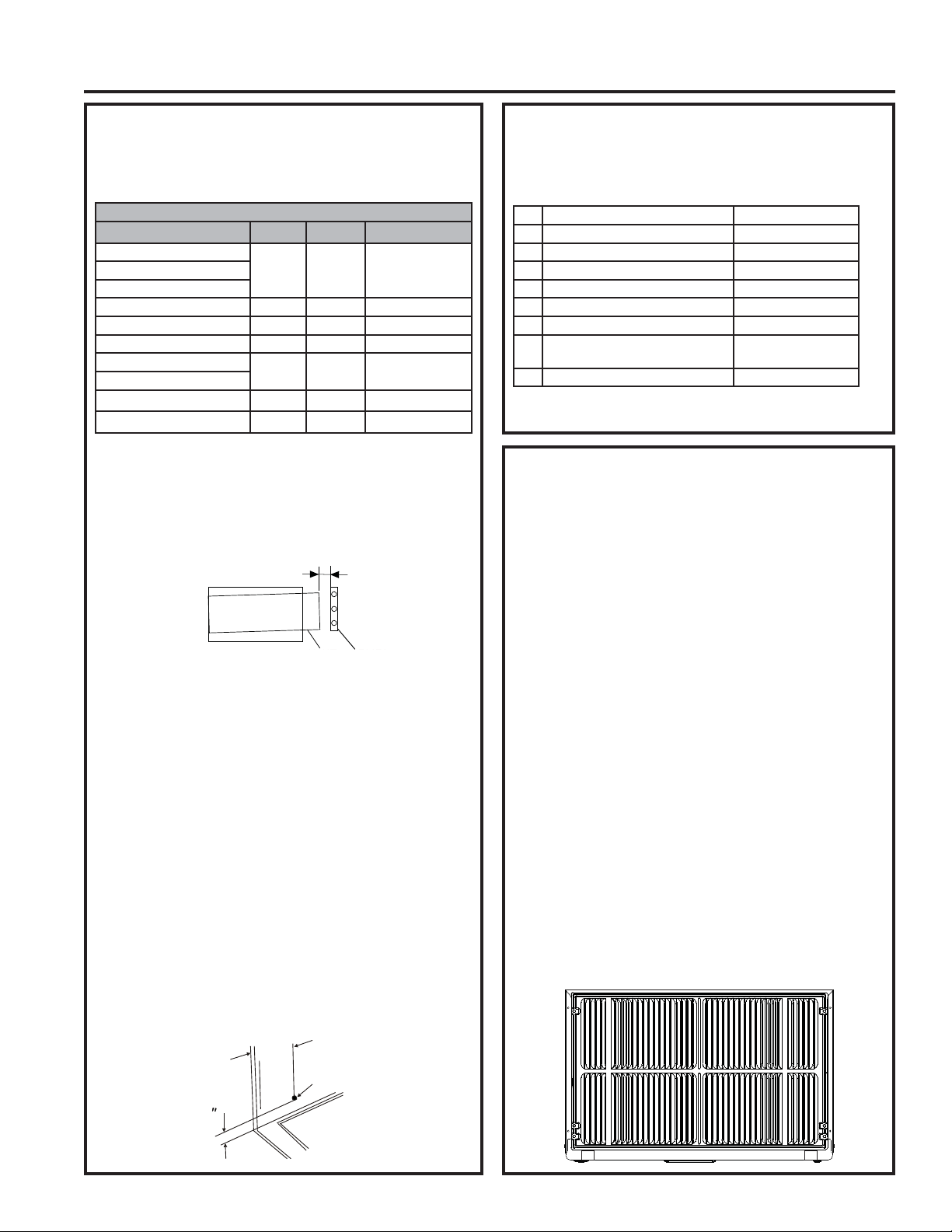
10 49-5000712 Rev. 1
Instructions d’installation
INSTRUCTIONS D’INSTALLATION
Installation dans une gaine murale
préexistante
1. Identifiez la marque de la gaine murale de votre
installation dans le tableau ci-dessous.
Dimensions de la gaine murale (pouces)
/DUJHXU +DXWHXU 3URIRQGHXU
White-Westinghouse
25-1/2 15-1/4 RU
Frigidaire
Carrier (Série 52F)
*(+RWSRLQW 26 15-5/8
Whirlpool 16-1/2 RU
Fedders/Emerson 16-3/4 16-3/4 or 19-3/4
Sears/Kenmore
25-3/4 18-5/8
Carrier (Série 51S)
Emerson/Fedders 26-3/4 15-3/4 15
Friedrich 16-3/4 16-3/4
REMARQUE :7RXWHVOHVJDLQHVPXUDOHVXWLOLVpHVSRXU
monter le nouveau climatiseur doivent présenter un bon état
structural et une grille arrière qui se fixe solidement à la gaine
ou à son rebord arrière qui sert de butée pour le climatiseur.
IMPORTANT : Une fois l’installation terminée, l’appareil de
UHPSODFHPHQW'2,7DYRLUXQHSHQWHYHUVO¶DUULqUHWHOTX¶LOOXVWUp
5HWLUH]OHYLHX[FOLPDWLVHXUGHODJDLQHPXUDOHHWSUpSDUH]
la gaine de la façon suivante :
Ŷ1HWWR\H]O¶LQWpULHXUQHSDVGpUDQJHUOHVMRLQWVG¶pWDQFKpLWp
Ŷ
/DJDLQHPXUDOHGRLWrWUHIL[pHVROLGHPHQWGDQVOHPXU
DYDQWG¶LQVWDOOHUOHFOLPDWLVHXU3RVH]SOXVGHFORXVRXGH
vis à travers la gaine dans le mur si nécessaire.
Ŷ5pSDUH]ODSHLQWXUHVLQpFHVVDLUH
3. S’il n’est pas présent, percez un trou de 1/8 po pour fixer
le fil de terre fourni sur le côté gauche de la gaine murale
(voir les dimensions approximatives de l’emplacement
du trou sur l’illustration ci-dessous). Utilisez la rondelle
dentée et la vis pointue pour fixer une extrémité du fil
de terre rayé vert fourni à l’intérieur de la gaine murale.
/DURQGHOOHGHQWpHGRLWVHVLWXHUHQWUHO¶°LOOHWGXILOHWOD
gaine murale. VEILLEZ À NE PAS TROP SERRER LA
VIS.7LUH]O¶H[WUpPLWpOLEUHGXILOGHWHUUHjO¶H[WpULHXUGX
devant de la gaine, et courbez-le temporairement vers le
bas et autour du bord inférieur de la gaine. Ce fil de terre
sera fixé plus tard au cadre du climatiseur une fois celui-
ci installé.
Installation dans une gaine murale
préexistante (suite)
3UpSDUH]ODJDLQHPXUDOHSRXUO¶LQVWDOODWLRQGXQRXYHO
appareil selon les instructions de la marque.
1 Emerson 15 po (prof.)
2 Fedders 19-3/4 po (prof.)
3 Fedders or Friedrich 16-3/4 po (prof.)
4 *(+RWSRLQW SRSURI
5 Sears or Carrier (Série 51S) 18-5/8 po (prof.)
6 Whirlpool SRSURI
Whirlpool 23 po (prof.)
8 White-Westinghouse/
Frigidaire/Carrier (Série 52F)
´SR
(prof.)
9 White-Westinghouse/Frigidaire 22 po (prof.)
5. Identifiez le type de votre gaine murale et suivez les
instructions pour ce type dans les pages suivantes.
IMPORTANT - AVANT DE COMMENCER
Ŷ/DSHUIRUPDQFHGHFHWDSSDUHLOUpVXOWHGXIDLWTX¶LOHVW
doté de deux entrées d’air à l’arrière.
Ŷ
Il est très important de respecter ces instructions afin que
l’appareil fonctionne à son efficacité maximale.
ŶS’il s’agit d’une gaine existante dotée d’une grille arrière, il peut
être nécessaire de remplacer cette dernière par l’une incluse
avec l’unité dans la trousse d’accessoires. Si la nouvelle
grille arrière est trop petite pour l’ouverture arrière de la gaine,
utilisez la grille en plastique noire. Assurez-vous de la fixer bien
en place à l’aide des vis, des rondelles et des passe-fils fournis.
POUR UNE MEILLEURE EFFICACITÉ, UTILISEZ
LE PANNEAU À ÉVENTS ARRIÈRE
Installation d’une nouvelle grille fournie avec l’appareil.
5HWLUH]ODJULOOHH[LVWDQWH([FHSWLRQ*(SR
3ODFH]ODJULOOHLQFOXVHDYHFOHQRXYHDXFOLPDWLVHXUYHUV
l’arrière de la gaine.
3. Faites des marques à travers les positions des trous.
3HUFH]jWUDYHUVOHVUHERUGVGHJDLQHjO¶DLGHG¶XQIRUHW
1/8 po.
5. Fixez la nouvelle grille avec des vis autotaraudeuses et
des rondelles.
,OHVW75Ê6,03257$17TXHODJULOOHVRLWSODFpH
exactement tel qu’illustré ci-dessous.
2QSHXWODLVVHUODSOXSDUWGHVJULOOHVGpFRUDWLYHV
extérieures en place pourvu que l’on installe la grille
appropriée pour diriger l’air à l’intérieur.
REAR
Wall Sleeve
UNIT
LEVEL
FRONT
to
3
Gaine murale
$55,Ê5(
$9$17
1,9($8$33$5(,/
1/4 à 3/16 po
1
3
Max.
1/8
Hole
3 po
max.
7URX
1/8 po
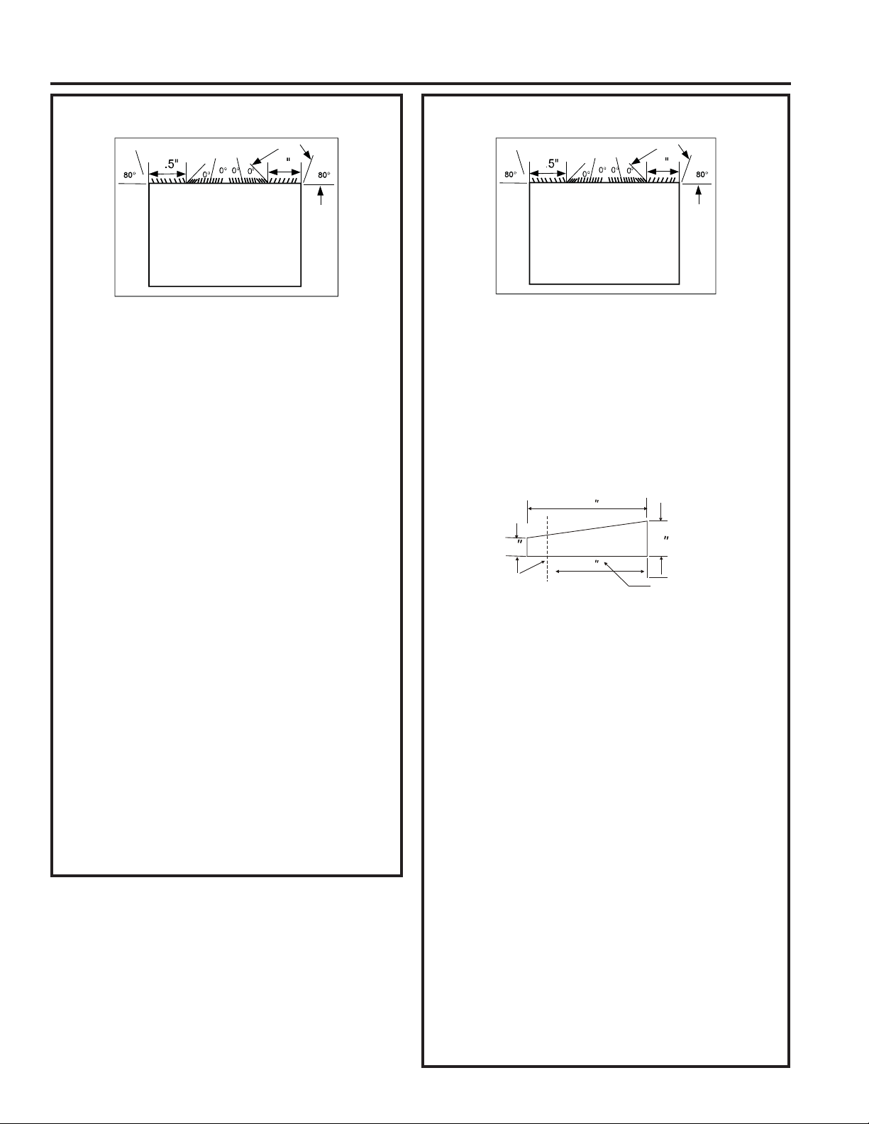
49-5000712 Rev. 1 11
INSTRUCTIONS D’INSTALLATION
Instructions d’installation
Emerson (15 po prof.)
4
4
3
8
3
8
5HWLUH]ODJULOOHDUULqUHH[LVWDQWHFRPPHLOOXVWUpjOD
page 9 de ce manuel et remplacez-la par le panneau à
évents arrière fourni.
REMARQUE : 9RXVGHYUH]SHXWrWUHSHUFHUGHVWURXVGDQV
le rebord de la gaine existante pour l’adaptation à la nouvelle
grille arrière.
)L[H]XQMRLQWG¶pWDQFKpLWpGH[[SRGHORQJ
DXFHQWUHGDQVOHKDXWGHODJDLQH5HWLUH]ODGRXEOXUHGH
papier et pressez en position.
)L[H]GHX[MRLQWVG¶pWDQFKpLWpGH[[SRGH
long sur les côtés gauche et droit de la gaine.
&RXSH]GHX[MRLQWVG¶pWDQFKpLWpGH[[SRHQ
longueurs de 14 po et fixez-les sur les sections verticales
de la grille arrière.
5. Fixez deux (2) blocs de centrage/support de 4 1/2 x 3
1/2 x 1 1/2 po, un sur chaque côté de la paroi latérale.
3ODFH]OHVDXFHQWUHGHODSDURLODWpUDOHDYHFO¶H[WUpPLWp
biseautée orientée vers l’ouverture.
6. Glissez l’appareil dans la gaine.
$YDQWGHJOLVVHUFRPSOqWHPHQWMXVTX¶jO¶DUULqUHUHWLUH]
la deuxième vis à partir de l’avant du côté gauche de
l’appareil.
5HWLUH]ODURQGHOOHHQSODVWLTXHGHODYLV
9LVVH]HWIL[H]O¶DXWUHH[WUpPLWpGXILOGHWHUUHVXU
l’appareil. Assurez-vous que la rondelle dentée repose
contre la carrosserie.
10. Glissez l’appareil complètement à l’arrière pour assurer
une bonne étanchéité, en vérifiant que le fil de terre ne
s’emmêle pas.
11. Si vous avez de la difficulté à monter la grille sur la gaine,
suivez les instructions sur le montage direct à la page 16.
eWDQFKpLVH]HWHQFDGUH]O¶DSSDUHLOWHOTXHGpFULWjOD
SDJH
Fedders (19-3/4 po prof.)
4
4
3
8
3
8
5HWLUH]ODJULOOHDUULqUHH[LVWDQWHFRPPHLOOXVWUpjOD
page 9 de ce manuel et remplacez-la par le panneau à
évents arrière fourni.
REMARQUE : 9RXVGHYUH]SHXWrWUHSHUFHUGHVWURXVGDQVOH
rebord de la gaine existante pour l’adaptation à la nouvelle grille
arrière.
2 Fixez deux (2) blocs de centrage/support de 4 1/2 x 3
1/2 x 1 1/2 po, un sur chaque côté de la paroi latérale.
3ODFH]OHVDXFHQWUHGHODSDURLODWpUDOHDYHFO¶H[WUpPLWp
biseautée orientée vers l’ouverture.
&RXSH]GHX[EORFVHVSDFHXUVELVHDXWpVGHSR
illustrés ci-dessous, en deux parties.
/DVHFWLRQGHSRHVWSODFpHGHYDQWODQHUYXUHVXUOD
base avec l’extrémité biseautée orientée vers l’arrière de
ODJDLQH/DSDUWLHUHVWDQWHVHUDSODFpHGHUULqUHODQHUYXUH
aussi inclinée vers l’arrière de la gaine. Cela procure une
inclinaison arrière à l’appareil.
)L[H]XQMRLQWG¶pWDQFKpLWpGH[[SRGHORQJ
DXFHQWUHGDQVOHKDXWGHODJDLQH5HWLUH]ODGRXEOXUHGH
papier et pressez en position.
)L[H]GHX[MRLQWVG¶pWDQFKpLWpGH[[SRGH
long sur les côtés gauche et droit de la gaine.
&RXSH]GHX[MRLQWVG¶pWDQFKpLWpGH[[SRGH
long et fixez-les sur les sections verticales de la grille arrière.
8. Glissez l’appareil dans la gaine.
$YDQWGHJOLVVHUFRPSOqWHPHQWMXVTX¶jO¶DUULqUHUHWLUH]
la deuxième vis à partir de l’avant du côté gauche de
l’appareil.
5HWLUH]ODURQGHOOHHQSODVWLTXHGHODYLV
9LVVH]HWIL[H]O¶DXWUHH[WUpPLWpGXILOGHWHUUHVXU
l’appareil. Assurez-vous que la rondelle dentée repose
contre la carrosserie.
12. Glissez l’appareil complètement à l’arrière pour assurer
une bonne étanchéité, en vérifiant que le fil de terre ne
s’emmêle pas.
13. Si vous avez de la difficulté à monter la grille sur la
gaine, suivez les instructions sur le montage direct à la
page 16.
eWDQFKpLVH]HWHQFDGUH]O¶DSSDUHLOWHOTXHGpFULWjOD
SDJH
9XHGHGHVVXV 9XHGHGHVVXV
eYHQWVDUULqUHeYHQWVDUULqUH
Cut Here
3
/
4
17
Tapered Spacer Block
1
Protection Paper
4
Couper ici
Doublure de
papier protectrice
%ORFHVSDFHXUELVHDXWp
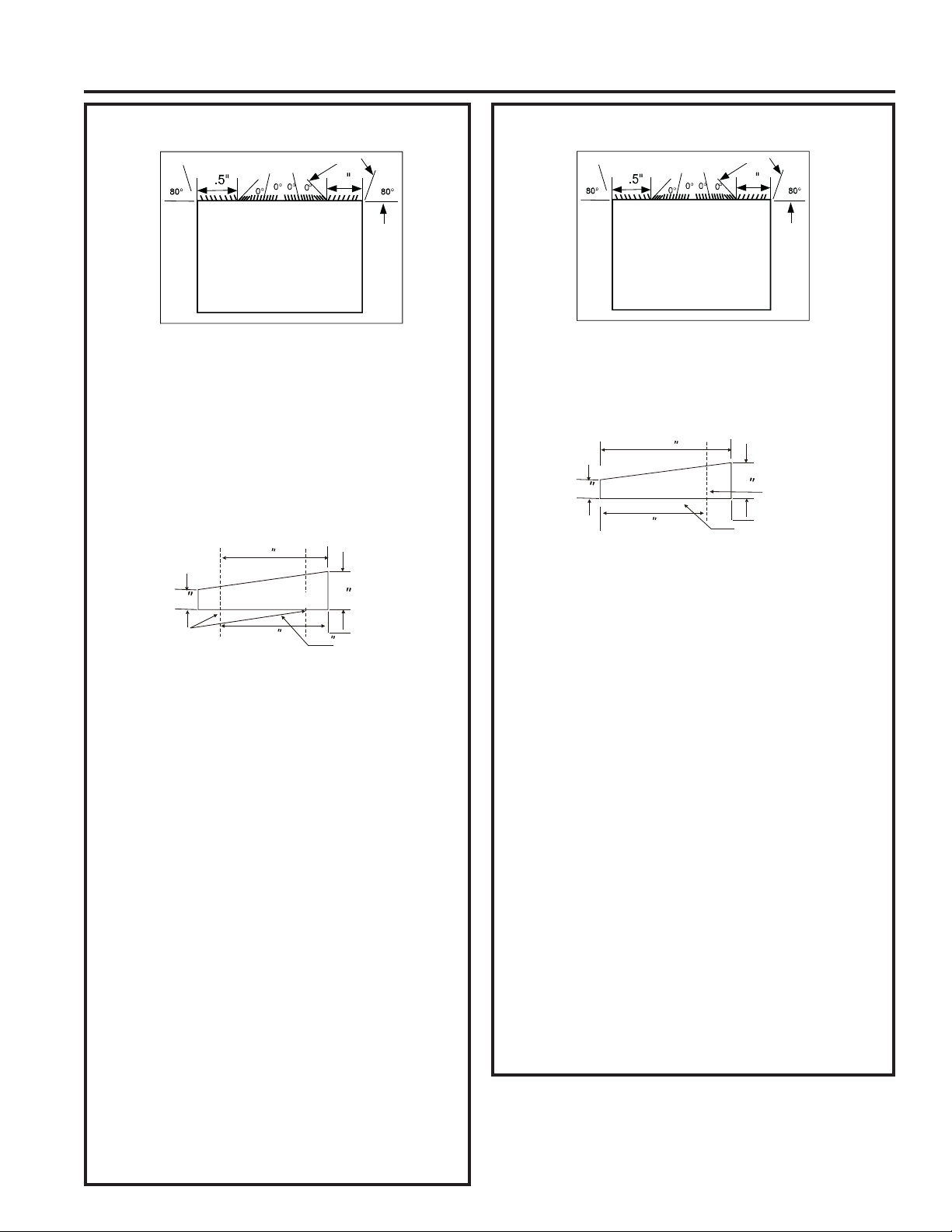
12 49-5000712 Rev. 1
INSTRUCTIONS D’INSTALLATION
Instructions d’installation
Fedders ou Friedrich (16-3/4 po prof.)
5HWLUH]ODJULOOHDUULqUHH[LVWDQWHFRPPHLOOXVWUpjOD
page 9 de ce manuel et remplacez-la par le panneau à
évents arrière fourni.
REMARQUE : 9RXVGHYUH]SHXWrWUHSHUFHUGHVWURXVGDQV
le rebord de la gaine existante pour l’adaptation à la nouvelle
grille arrière.
2. Fixez deux (2) blocs de centrage/support de 4 1/2 x 3 1/2
[SRXQVXUFKDTXHF{WpGHODSDURLODWpUDOH3ODFH]
les au centre de la paroi latérale avec l’extrémité biseautée
orientée vers l’ouverture.
&RXSH]GHX[EORFVHVSDFHXUVELVHDXWpVGHSR
illustrés ci-dessous, en trois parties.
/DVHFWLRQGHòSRHVWSODFpHGHYDQWODQHUYXUHVXUODEDVH
avec l’extrémité biseautée orientée vers l’arrière de la gaine.
Coupez la partie restante à 12 1/2 po et placez-la derrière la
nervure aussi inclinée vers l’arrière de la gaine. Cela procure
une inclinaison arrière à l’appareil.
)L[H]XQMRLQWG¶pWDQFKpLWpGH[[SRGHORQJ
DXFHQWUHGDQVOHKDXWGHODJDLQH5HWLUH]ODGRXEOXUHGH
papier et pressez en position.
)L[H]GHX[MRLQWVG¶pWDQFKpLWpGH[[SRGHVXU
les côtés gauche et droit de la gaine.
&RXSH]GHX[MRLQWVG¶pWDQFKpLWpGH[[SRHQ
longueurs de 14 po et fixez-les sur les sections verticales
de la grille arrière
.
8. Glissez l’appareil dans la gaine.
$YDQWGHJOLVVHUFRPSOqWHPHQWMXVTX¶jO¶DUULqUHUHWLUH]
la deuxième vis à partir de l’avant du côté gauche de
l’appareil.
5HWLUH]ODURQGHOOHHQSODVWLTXHGHODYLV
9LVVH]HWIL[H]O¶DXWUHH[WUpPLWpGXILOGHWHUUHVXU
l’appareil. Assurez-vous que la rondelle dentée repose
contre la carrosserie.
12. Glissez l’appareil complètement à l’arrière pour assurer
une bonne étanchéité, en vérifiant que le fil de terre ne
s’emmêle pas.
13. Si vous avez de la difficulté à monter la grille sur la
gaine, suivez les instructions sur le montage direct à
la page 16.
eWDQFKpLVH]HWHQFDGUH]O¶DSSDUHLOWHOTXHGpFULWjOD
SDJH
GE/Hotpoint (16-7/8 po prof.)
4
4
3
8
3
8
1. Conservez la grille arrière existante.
¬,¶DLGHG¶XQHSLQFHjEHFHIILOpFKDQJH]OHVpYHQWV
directionnels de la grille extérieure selon l’illustration ci-dessus.
&RXSH]GHX[EORFVHVSDFHXUVELVHDXWpVGHSRHQ
deux parties tel qu’illustré ci-dessous.
4. Installez la section de 13 po avec l’extrémité biseautée
à 1/2 po de l’arrière de la gaine. Cela procure une
inclinaison arrière à l’appareil.
)L[H]XQMRLQWG¶pWDQFKpLWpGH[[SRGHORQJ
DXFHQWUHGDQVOHKDXWGHODJDLQH5HWLUH]ODGRXEOXUHGH
papier et pressez en position.
)L[H]GHX[MRLQWVG¶pWDQFKpLWpGH[[SRGH
sur les côtés gauche et droit de la gaine.
&RXSH]GHX[MRLQWVG¶pWDQFKpLWpGH[[SRHQ
longueurs de 14 po et fixez-les sur les sections verticales
de la grille arrière.
8. Centrez l’appareil et glissez l’appareil dans la gaine avec
soin.
$YDQWGHJOLVVHUFRPSOqWHPHQWMXVTX¶jO¶DUULqUHUHWLUH]
la deuxième vis à partir de l’avant du côté gauche de
l’appareil.
5HWLUH]ODURQGHOOHHQSODVWLTXHGHODYLV
9LVVH]HWIL[H]O¶DXWUHH[WUpPLWpGXILOGHWHUUHVXU
l’appareil. Assurez-vous que la rondelle dentée repose
contre la carrosserie.
12. Glissez l’appareil complètement à l’arrière pour assurer
une bonne étanchéité, en vérifiant que le fil de terre ne
s’emmêle pas.
13. Si vous avez de la difficulté à monter la grille sur la
gaine, suivez les instructions sur le montage direct à la
page 16.
eWDQFKpLVH]HWHQFDGUH]O¶DSSDUHLOWHOTXHGpFULWjOD
SDJH
9XHGHGHVVXV
4
4
3
8
3
8
9XHGHGHVVXV
eYHQWVDUULqUH
eYHQWVDUULqUH
Cut Here
3
/
4
17
Tapered Spacer Block
1
Protection Paper
Backing
12-1/2
2-1/2
Couper ici
Doublure de
papier protectrice
%ORFHVSDFHXUELVHDXWp
3
/
4
17
Tapered Spacer Block
1
Protection Paper
Backing
Cut Here
13
Couper ici
Doublure de
papier protectrice
%ORFHVSDFHXUELVHDXWp
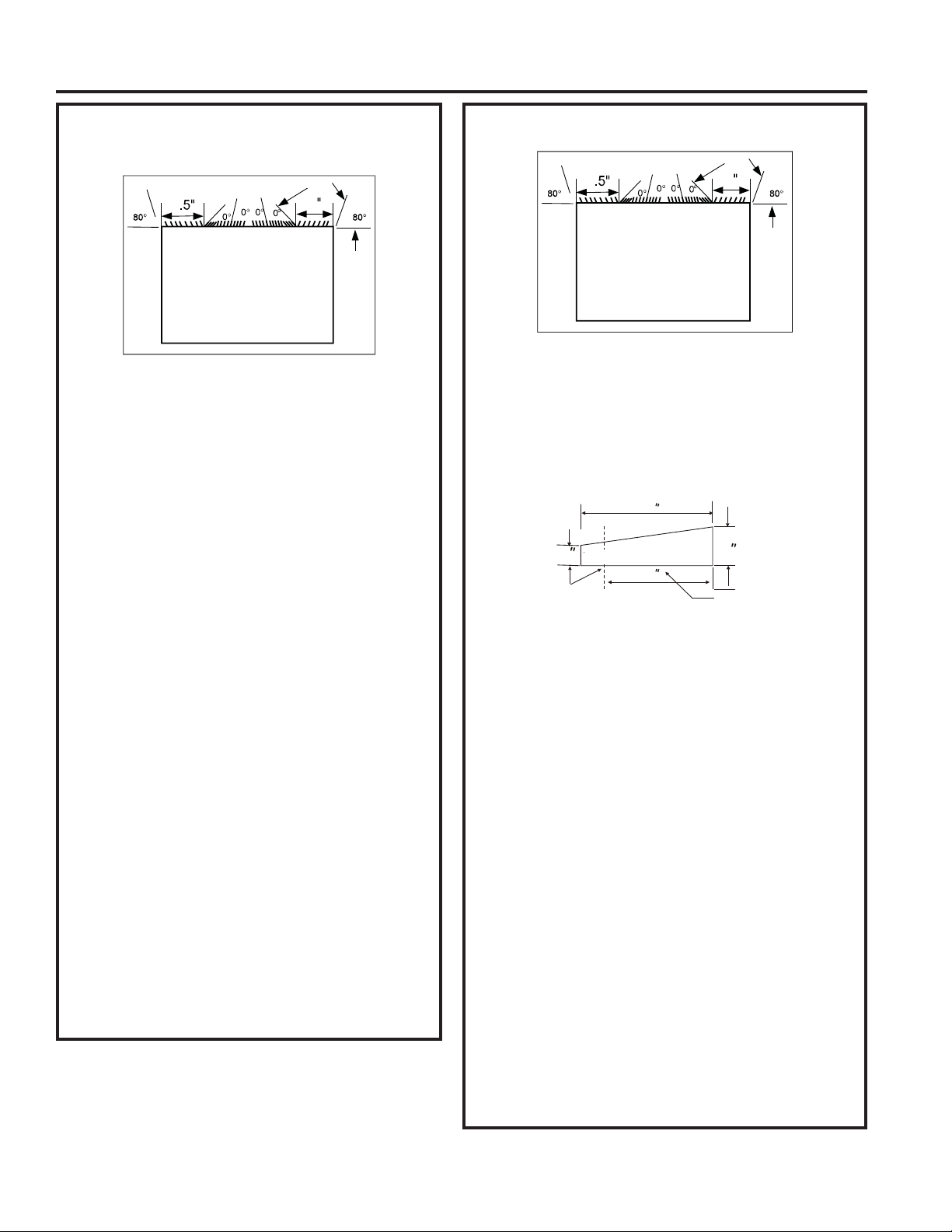
49-5000712 Rev. 1 13
Instructions d’installation
Sears ou Carrier Série 51S
(18-5/8 po prof.)
4
4
3
8
3
8
5HWLUH]ODJULOOHDUULqUHH[LVWDQWHFRPPHLOOXVWUpjOD
page 9 de ce manuel et remplacez-la par le panneau à
évents arrière fourni.
REMARQUE : 9RXVGHYUH]SHXWrWUHSHUFHUGHVWURXVGDQV
le rebord de la gaine existante pour l’adaptation à la nouvelle
grille arrière.
2. Installez deux (2) blocs espaceurs biseautés sur le
plancher de la gaine. Cela procure une inclinaison arrière
à l’appareil.
3. Installez-les avec l’extrémité biseautée à 1/2 po de
l’arrière de la gaine. Cela procure une inclinaison arrière à
l’appareil.
)L[H]XQMRLQWG¶pWDQFKpLWpGH[[SRGHORQJ
DXFHQWUHGDQVOHKDXWGHODJDLQH5HWLUH]ODGRXEOXUHGH
papier et pressez en position.
)L[H]GHX[MRLQWVG¶pWDQFKpLWpGH[[SRGHVXU
les côtés gauche et droit de la gaine.
&RXSH]GHX[MRLQWVG¶pWDQFKpLWpGH[[SRHQ
longueurs de 14 po et fixez-les sur les sections verticales
de la grille arrière.
&HQWUH]O¶DSSDUHLOHWJOLVVH]O¶DSSDUHLOGDQVODJDLQHDYHF
soin.
$YDQWGHJOLVVHUFRPSOqWHPHQWMXVTX¶jO¶DUULqUHUHWLUH]
la deuxième vis à partir de l’avant du côté gauche de
l’appareil.
5HWLUH]ODURQGHOOHHQSODVWLTXHGHODYLV
9LVVH]HWIL[H]O¶DXWUHH[WUpPLWpGXILOGHWHUUHVXU
l’appareil. Assurez-vous que la rondelle dentée repose
contre la carrosserie.
11. Glissez l’appareil complètement à l’arrière pour assurer
une bonne étanchéité, en vérifiant que le fil de terre ne
s’emmêle pas.
12. Si vous avez de la difficulté à monter la grille sur la gaine,
suivez les instructions sur le montage direct à la page 16.
eWDQFKpLVH]HWHQFDGUH]O¶DSSDUHLOWHOTXHGpFULWjOD
SDJH
Whirlpool (17-1/8 po prof.)
4
4
3
8
3
8
5HWLUH]ODJULOOHDUULqUHH[LVWDQWHFRPPHLOOXVWUpjOD
page 9 de ce manuel et remplacez-la par le panneau à
évents arrière fourni.
REMARQUE : 9RXVGHYUH]SHXWrWUHSHUFHUGHVWURXVGDQVOH
rebord de la gaine existante pour l’adaptation à la nouvelle grille
arrière.
&RXSH]GHX[EORFVHVSDFHXUVELVHDXWpVGHSRHQ
deux parties tel qu’illustré ci-dessous.
3. Installez la section de 13 po sur le plancher de la gaine.
Cela procure une inclinaison arrière à l’appareil.
)L[H]XQMRLQWG¶pWDQFKpLWpGH[[SRGHORQJ
DXFHQWUHGDQVOHKDXWGHODJDLQH5HWLUH]ODGRXEOXUHGH
papier et pressez en position.
)L[H]GHX[MRLQWVG¶pWDQFKpLWpGH[[SRGH
sur les côtés gauche et droit de la gaine.
&RXSH]GHX[MRLQWVG¶pWDQFKpLWpGH[[SRHQ
longueurs de 14 po et fixez-les sur les sections verticales
de la grille arrière.
&HQWUH]O¶DSSDUHLOHWJOLVVH]O¶DSSDUHLOGDQVODJDLQHDYHF
soin.
$YDQWGHJOLVVHUFRPSOqWHPHQWMXVTX¶jO¶DUULqUHUHWLUH]
la deuxième vis à partir de l’avant du côté gauche de
l’appareil.
5HWLUH]ODURQGHOOHHQSODVWLTXHGHODYLV
9LVVH]HWIL[H]O¶DXWUHH[WUpPLWpGXILOGHWHUUHVXU
l’appareil. Assurez-vous que la rondelle dentée repose
contre la carrosserie.
11. Glissez l’appareil complètement à l’arrière pour assurer
une bonne étanchéité, en vérifiant que le fil de terre ne
s’emmêle pas.
12. Si vous avez de la difficulté à monter la grille sur la
gaine, suivez les instructions sur le montage direct à la
page 16.
eWDQFKpLVH]HWHQFDGUH]O¶DSSDUHLOWHOTXHGpFULWjOD
SDJH
9XHGHGHVVXV
9XHGHGHVVXV
eYHQWVDUULqUH
eYHQWVDUULqUH
3
/
4
17
Tapered Spacer Block
1
Protection Paper
Backing
Cut Here
13
Couper ici
Doublure de papier
protectrice
%ORFHVSDFHXUELVHDXWp
INSTRUCTIONS D’INSTALLATION
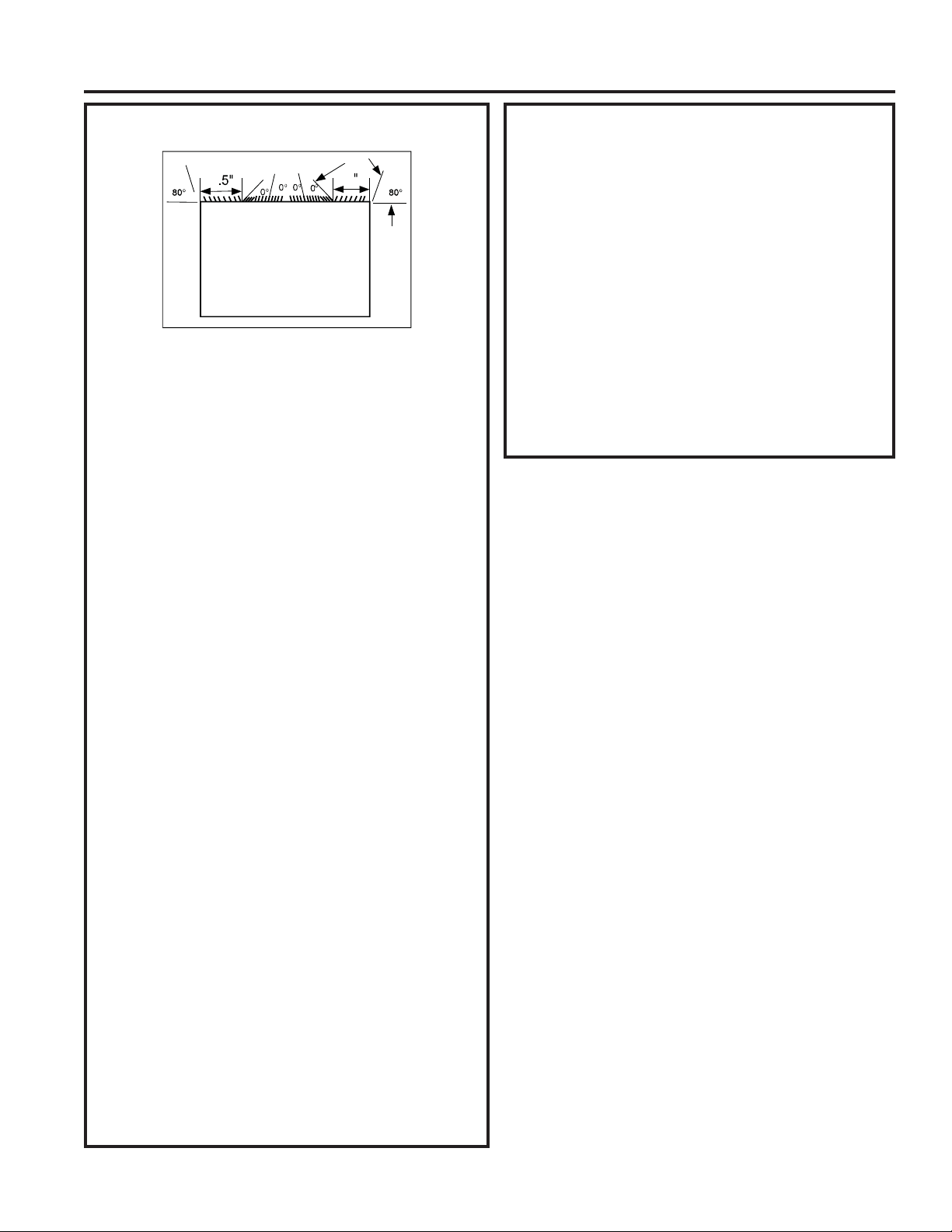
14 49-5000712 Rev. 1
INSTRUCTIONS D’INSTALLATION
Instructions d’installation
Whirlpool (23 po prof.)
4
4
3
8
3
8
5HWLUH]ODJULOOHDUULqUHH[LVWDQWHFRPPHLOOXVWUpjOD
page 9 de ce manuel et remplacez-la par le panneau à
évents arrière fourni.
REMARQUE : 9RXVGHYUH]SHXWrWUHSHUFHUGHVWURXVGDQVOH
rebord de la gaine existante pour l’adaptation à la nouvelle grille
arrière.
En raison de la profondeur augmentée de l’appareil,
tentez d’abord une pose à sec à l’aide de la méthode
décrite ci-dessous :
3ODFH]GHX[MRLQWVG¶pWDQFKpLWpGH[[SR
contre chaque côté.
3. Glissez avec soin l’appareil et vérifiez si la distance qui
dépasse de la gaine sera suffisante une fois le cadre de
finition fixé.
4. Si la position est correcte, retirez l’appareil et allez à
l’étape suivante. Si ce n’est pas le cas, allez à l’étape 9.
)L[H]XQMRLQWG¶pWDQFKpLWpGH[[SRGHORQJ
DXFHQWUHGDQVOHKDXWGHODJDLQH5HWLUH]ODGRXEOXUHGH
papier et pressez en position.
)L[H]GHX[MRLQWVG¶pWDQFKpLWpGH[[SRGH
long sur les côtés gauche et droit de la gaine.
&RXSH]GHX[MRLQWVG¶pWDQFKpLWpGH[[SRHQ
longueurs de 14 po et fixez-les sur les sections verticales
de la grille.
8. Installez les blocs espaceurs biseautés sur le plancher de
la gaine. Maintenant allez à l’étape 15.
Utilisez les prochaines étapes si l’appareil nécessite une
extension supplémentaire dans la pièce :
)L[H]OHMRLQWG¶pWDQFKpLWpGH[[SRGHORQJVXUOD
partie verticale solide de la grille arrière.
10. Fixez quatre (4) blocs de mousse de 4 1/2 x 3 1/2 x 1 1/2
SRDYHFODIHQWHFKHYDXFKDQWOHMRLQWDXGHVVXV
11. Installez le diviseur dans les fentes des blocs de mousse.
9RXVGHYUH]SHXWrWUHFRXSHUODORQJXHXUjODERQQH
dimension.
5pSpWH]OHVpWDSHVjSRXUO¶DXWUHSDUWLHYHUWLFDOHGH
la grille.
)L[H]GHX[MRLQWVG¶pWDQFKpLWpGH[[SROH
long des côtés de la gaine à nouveau en vous assurant
TXHOHVMRLQWVVRQWjpJDOLWp
&RXSH]OHMRLQWG¶pWDQFKpLWpGH[[SRSRXU
O¶DGDSWHUDXKDXWGHODJDLQH/HVSLqFHVGRLYHQWDUULYHUj
égalité avec le bord du diviseur.
Whirlpool (23 po prof.) suite
15. Centrez l’appareil et glissez l’appareil dans la gaine
avec soin.
$YDQWGHJOLVVHUFRPSOqWHPHQWMXVTX¶jO¶DUULqUHUHWLUH]
la première vis à partir de l’avant du côté gauche de
l’appareil.
5HWLUH]ODURQGHOOHHQSODVWLTXHGHODYLV
9LVVH]HWIL[H]O¶DXWUHH[WUpPLWpGXILOGHWHUUHVXU
l’appareil. Assurez-vous que la rondelle dentée repose
contre la carrosserie.
19. Glissez l’appareil complètement à l’arrière pour assurer
une bonne étanchéité, en vérifiant que le fil de terre ne
s’emmêle pas.
20. Si vous avez de la difficulté à monter la grille sur la
gaine, suivez les instructions sur le montage direct à la
page 16.
eWDQFKpLVH]HWHQFDGUH]O¶DSSDUHLOWHOTXHGpFULWjOD
SDJH
9XHGHGHVVXV
eYHQWVDUULqUH
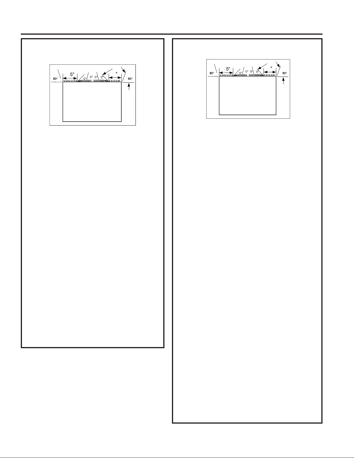
49-5000712 Rev. 1 15
Instructions d’installation
White-Westinghouse/Frigidaire/Carrier
Série 52F (16 po + 17-1/2 po prof.)
4
4
3
8
3
8
5HWLUH]ODJULOOHDUULqUHH[LVWDQWHFRPPHLOOXVWUpjOD
page 9 de ce manuel et remplacez-la par le panneau à
évents arrière fourni.
REMARQUE : 9RXVGHYUH]SHXWrWUHSHUFHUGHVWURXV
dans le rebord de la gaine existante pour l’adaptation à la
nouvelle grille arrière.
)L[H]XQMRLQWG¶pWDQFKpLWpGH[[SRGH
ORQJDXFHQWUHGDQVOHKDXWGHODJDLQH5HWLUH]OD
doublure de papier et pressez en position.
)L[H]GHX[MRLQWVG¶pWDQFKpLWpGH[[SRGH
long sur les côtés gauche et droit de la gaine.
)L[H]GHX[MRLQWVG¶pWDQFKpLWpGH[[SRGH
long verticalement à 4,5 po du côté gauche de la gaine
et 4 po du côté droit de la gaine.
5. Centrez l’appareil et glissez l’appareil dans la gaine
avec soin.
$YDQWGHJOLVVHUFRPSOqWHPHQWMXVTX¶jO¶DUULqUHUHWLUH]
la deuxième vis à partir de l’avant du côté gauche de
l’appareil.
5HWLUH]ODURQGHOOHHQSODVWLTXHGHODYLV
9LVVH]HWIL[H]O¶DXWUHH[WUpPLWpGXILOGHWHUUHVXU
l’appareil. Assurez-vous que la rondelle dentée repose
contre la carrosserie.
9. Glissez l’appareil complètement à l’arrière pour assurer
une bonne étanchéité, en vérifiant que le fil de terre ne
s’emmêle pas.
10. Si vous avez de la difficulté à monter la grille sur la
gaine, suivez les instructions sur le montage direct à
la page 16.
eWDQFKpLVH]HWHQFDGUH]O¶DSSDUHLOWHOTXHGpFULWjOD
SDJH
White-Westinghouse ou Frigidaire
(22 po prof.)
5HWLUH]ODJULOOHDUULqUHH[LVWDQWHFRPPHLOOXVWUpjOD
page 9 de ce manuel et remplacez-la par le panneau à
évents arrière fourni.
REMARQUE : 9RXVGHYUH]SHXWrWUHSHUFHUGHVWURXVGDQVOH
rebord de la gaine existante pour l’adaptation à la nouvelle grille
arrière.
En raison de la profondeur augmentée de l’appareil,
tentez d’abord une pose à sec à l’aide de la méthode
décrite ci-dessous :
3ODFH]GHX[MRLQWVG¶pWDQFKpLWpGH[[SR
contre chaque côté.
3. Glissez avec soin l’appareil et vérifiez si la distance qui
dépasse de la gaine sera suffisante une fois le cadre de
garniture fixé.
4. Si la position est correcte, retirez l’appareil et allez à
l’étape suivante. Si ce n’est pas le cas, allez à l’étape 8.
)L[H]XQMRLQWG¶pWDQFKpLWpGH[[SRGHORQJ
sur les côtés gauche et droit de la gaine.
&RXSH]XQMRLQWG¶pWDQFKpLWpGH[[SR
en longueurs de 14 po et fixez-les verticalement sur la
grille arrière à 4,5 po du côté gauche de la gaine et 4
po du côté droit de la gaine.
)L[H]XQMRLQWG¶pWDQFKpLWpGH[[SRGHORQJ
DXFHQWUHGDQVOHKDXWGHODJDLQH5HWLUH]ODGRXEOXUHGH
SDSLHUHWSUHVVH]HQSRVLWLRQ3DVVH]jO¶pWDSH
Utilisez les prochaines étapes si l’appareil nécessite une
extension supplémentaire dans la pièce.
)L[H]OHMRLQWG¶pWDQFKpLWpGH[[SRGHORQJVXUOD
partie verticale solide de la grille arrière.
9. Fixez quatre (4) blocs de mousse de 4 1/2 x 3 1/2 x 1 1/2
SRDYHFODIHQWHFKHYDXFKDQWOHMRLQWDXGHVVXV
10.
,QVWDOOH]OHGLYLVHXUGDQVOHVIHQWHVGHVEORFVGHPRXVVH9RXV
devrez peut-être couper la longueur à la bonne dimension.
5pSpWH]OHVpWDSHVjSRXUO¶DXWUHSDUWLHYHUWLFDOHGH
la grille.
)L[H]GHX[MRLQWVG¶pWDQFKpLWpGH[[SROH
long des côtés de la gaine à nouveau en vous assurant
TXHOHVMRLQWVVRQWjpJDOLWp
&RXSH]OHMRLQWG¶pWDQFKpLWpGH[[SRSRXU
O¶DGDSWHUDXKDXWGHODJDLQH/HVSLqFHVGRLYHQWDUULYHU
à égalité avec le bord du diviseur.
14. Centrez l’appareil et glissez l’appareil dans la gaine avec soin.
$YDQWGHJOLVVHUFRPSOqWHPHQWMXVTX¶jO¶DUULqUHUHWLUH]OD
première vis à partir de l’avant du côté gauche de l’appareil.
5HWLUH]ODURQGHOOHHQSODVWLTXHGHODYLV
4
4
3
8
3
8
9XHGHGHVVXV
9XHGHGHVVXV
eYHQWVDUULqUH
eYHQWVDUULqUH
INSTRUCTIONS D’INSTALLATION
16 49-5000712 Rev. 1
INSTRUCTIONS D’INSTALLATION
Instructions d’installation
White-Westinghouse ou Frigidaire
(22 po prof.) suite
9LVVH]HWIL[H]O¶DXWUHH[WUpPLWpGXILOGHWHUUHVXU
l’appareil. Assurez-vous que la rondelle dentée repose
contre la carrosserie.
18. Glissez l’appareil complètement à l’arrière pour assurer
une bonne étanchéité, en vérifiant que le fil de terre ne
s’emmêle pas.
19. Si vous avez de la difficulté à monter la grille sur la
gaine, suivez les instructions sur le montage direct à la
page 16.
eWDQFKpLVH]HWHQFDGUH]O¶DSSDUHLOWHOTXHGpFULWjOD
SDJH
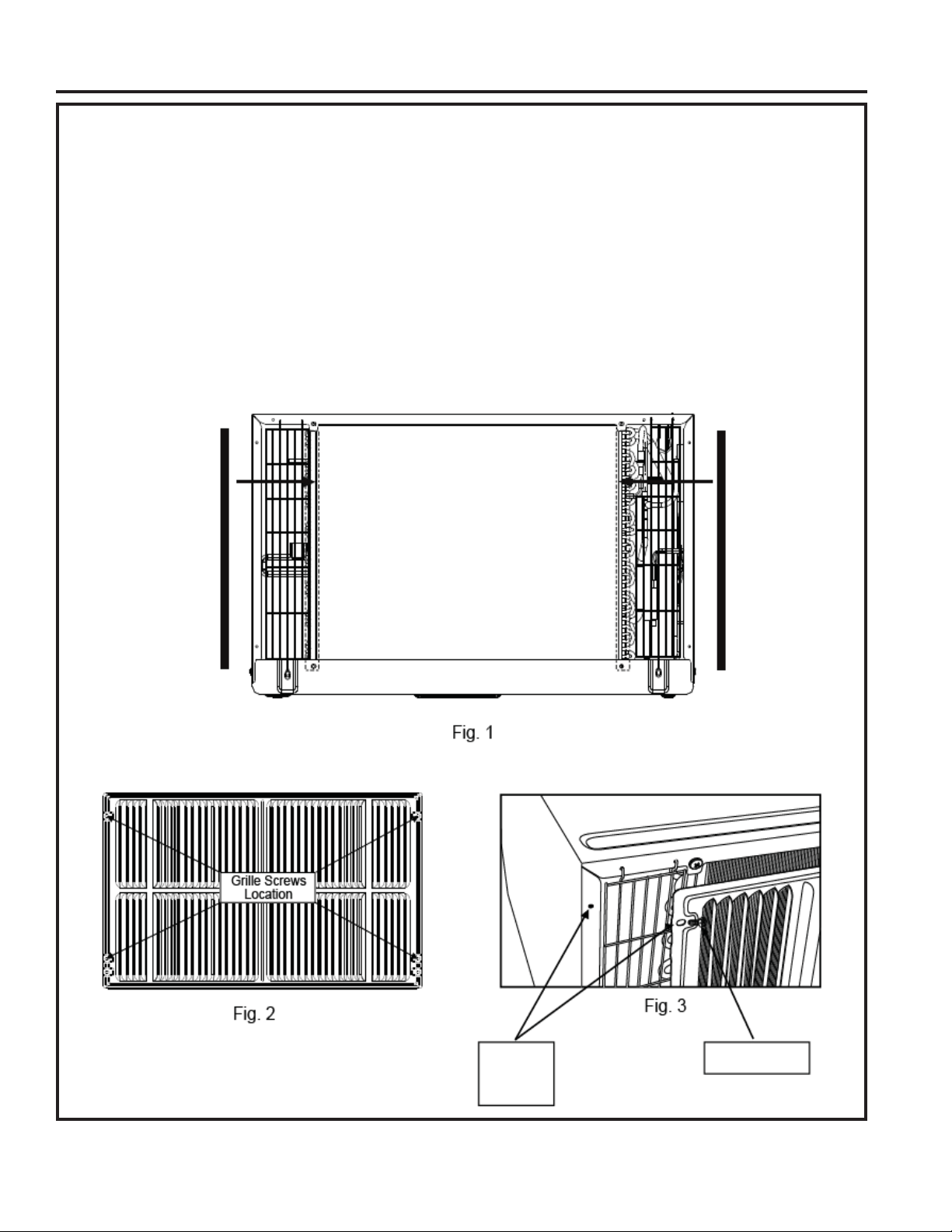
49-5000712 Rev. 1
Instructions d’installation
Montage direct de l’appareil :
/HVSUpFpGHQWHVGLUHFWLYHVVRQWODIDoRQSUpIpUpHGHPRQWHUXQHQRXYHOOHJULOOHDUULqUH/HUHQGHPHQWGHO¶DSSDUHLOHVW
légèrement meilleur et la possibilité de courants d’air est réduite. En dernier recours, on peut envisager le montage direct de
la grille sur l’appareil.
REMARQUE : /DJULOOHGRLWrWUHLQVWDOOpHDYDQWG¶LQVpUHUO¶DSSDUHLOGDQVODJDLQH
)L[H]OHVVHJPHQWVGHMRLQW[[SRWHOTX¶LOOXVWUp
3ODFH]ODJULOOHSDUGHVVXVO¶DUULqUHGHO¶DSSDUHLOHQYRXVDVVXUDQWTXH
D/HGRXEOHMHXGHWURXVGHYLVHVWGDQVOHEDV
E/HVDLOHWWHVGHODJULOOHVRQWRULHQWpHVjO¶pFDUWGHO¶DSSDUHLO
$OLJQH]OHKDXWGHODJULOOHDYHFOHKDXWGHO¶DSSDUHLO/HVXUSORPEGHFKDTXHF{WpGHYUDLWrWUHpJDO
4. Si des trous prépercés ne se trouvent pas sur l’appareil (certains modèles), percez avec soin quatre (4) trous de 1/8 po à
WUDYHUVODJULOOHHWGDQVOHUHERUGODWpUDOGHO¶DSSDUHLOHQYLURQòSRjSRGXKDXWHWGXEDVWHOTX¶LOOXVWUp
5. Installez 4 vis autotaraudeuses no 8 pour apposer la grille sur l’appareil.
6. Insérez l’appareil dans la gaine.
Joint
d’étanchéité
Joint
d’étanchéité
7URXGH
1/8 po
dans grille
et rebord
9LVQR
INSTRUCTIONS D’INSTALLATION
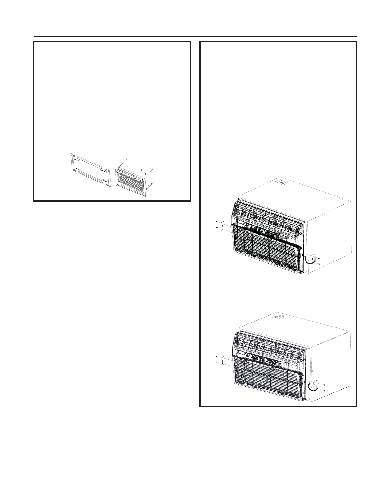
18 49-5000712 Rev. 1
Instructions d’installation
INSTRUCTIONS D’INSTALLATION
Instructions d’installation de la trousse
de finition
Ŷ,QVWDOOH]OHMRLQWGHERXUUDJHGH[[SRGHORQJ
entre la gaine murale et l’appareil. Un tournevis à lame
plate ou un couteau à mastic est recommandé
.
Ŷ$VVHPEOH]OHFDGUHGHILQLWLRQHQLQVpUDQWOHVSLqFHV
supérieure et inférieure dans les pièces latérales et
encliquetez-les en place
.
Ŷ7LUH]OHFRUGRQjWUDYHUVOHFDGUHGHILQLWLRQHWJOLVVH]
ODILQLWLRQSDUGHVVXVO¶DSSDUHLOMXVTX¶jFHTX¶HOOHVRLWj
égalité avec le mur ou la gaine murale
.
Assemble Trim
Installation des ferrures de sécurité
(Il est important d’installer ces ferrures
afin d’empêcher châssis d’être poussé
dans la pièce depuis l’extérieur.)
Ŷ0HVXUH]ODODUJHXUGHODJDLQHPXUDOHLQVWDOOpHHW
choisissez la ferrure de sécurité (24 ou 26 po) conçue
pour cette gaine.
Ŷ/HVIHUUXUHVGRLYHQWrWUHLQVWDOOpHVGHIDoRQTXHOHV
rebords s’accrochent derrière les rebords intérieurs de la
JDLQHPXUDOH¬O¶DLGHGHVYLVIRXUQLHVIL[H]OHVIHUUXUHV
sur les côtés du châssis
.
3RXUOHVJDLQHVGHSRWLUH]O¶DSSDUHLOOpJqUHPHQW
accrochez le rebord court de la ferrure 24 po derrière
OHERUGLQWpULHXUGHODJDLQHHW¿[H]ODIHUUXUHVXU
O¶DSSDUHLOjO¶DLGHGHVGHX[YLVIRXUQLHV5pSpWH]SRXUOH
F{WpRSSRVp3RXVVH]O¶DSSDUHLOMXVTX¶DXERXWGDQVOH
caisson.
3RXUOHVJDLQHVGHSRDFFURFKH]OHUHERUGFRXUWGH
la ferrure 26 po derrière le bord intérieur de la gaine
HW¿[H]ODIHUUXUHVXUO¶DSSDUHLOjO¶DLGHGHVGHX[YLV
IRXUQLHV5pSpWH]SRXUOHF{WpRSSRVp
Accrocher
le bord
intérieur
de la gaine
HW¿[HUVXU
l’appareil
A
ccrocher
le bord
intérieur
de la gaine
HW¿[HUVXU
l
’
appareil
A
ccrocher
le bord
intérieur
de la gaine
HW¿[HUVXU
l’a
pp
areil
Accrocher
le bord
intérieur
de la gaine
HW¿[HUVXU
l’appareil

49-5000712 Rev. 1 19
CONSEILS DE DÉPANNAGE
Conseils de dépannage… Avant d’appeler un réparateur
Problème Solution
Le climatiseur ne démarre
pas
La fiche du cordon est débranchée. Poussez la fiche fermement dans la prise murale.
Un fusible de la maison est grillé ou le disjoncteur est déclenché. Remplacez le fusible
par un fusible temporisé ou réenclenchez le disjoncteur.
Le dispositif de courant de la fiche est déclenché. Pressez le bouton RESET
(réinitialisation).
L’appareil est éteint (OFF). Allumez l’appareil (ON).
L’air fourni par l’appareil
n’est pas suffisamment
froid
La température ambiante est sous 62°F (17°C). Il se peut que la climatisation s’active
seulement si la température ambiante passe au-dessus de 62°F (17°C).
Le capteur de température derrière le filtre à air touche peut-être le serpentin froid.
Éloignez-le du serpentin froid.
Le climatiseur est réglé à une température plus basse.
Le compresseur s’est arrêté en changeant de mode. Attendez 3 minutes après le
passage au mode COOL (climatisation).
La climatisation
fonctionne bien, mais la
pièce est trop chaude.
Du givre se forme sur le
serpentin de climatisation
derrière le panneau frontal
décoratif.
La température extérieure est sous 64°F (18°C). Pour dégivrer le serpentin, passez au
mode FAN ONLY (ventilateur seulement).
Le filtre à air est peut-être sale. Nettoyez le filtre. Consultez la section Entretien et
nettoyage. Pour dégivrer, passez au mode FAN ONLY.
Le réglage du thermostat est plus froid pour la climatisation de nuit. Pour dégivrer le
serpentin, passez au mode FAN ONLY. Ensuite, réglez la température à la valeur la plus
élevée.
Filtre à air sale, ou la circulation d’air est restreinte. Nettoyez le filtre à air. Consultez la
section Entretien et nettoyage.
Le réglage de température est trop élevé. Réglez la température à une valeur plus basse.
Les évents dirigent l’air incorrectement. Dirigez les évents de façon à améliorer la
distribution d’air.
Le devant de l’appareil est bloqué par des objets qui limitent la distribution d’air
(rideaux, stores, meubles, etc.). Libérez le devant de l’appareil.
Il se peut que des portes, fenêtres, registres, etc. soient ouverts. Fermez les portes,
fenêtres, registres.
On a allumé l’appareil récemment dans une pièce très chaude. Allouez plus de temps
pour dissiper la chaleur « emmagasinée » dans les murs, le plafond, le plancher et les
murs.
Le climatiseur s’allume et
s’éteint rapidement
Le filtre à air est sale, la circulation d’air est restreinte. Nettoyez le filtre à air.
Outside temperature extremely hot. Set FAN speed to a higher setting to cool outdoor
cooling coil.
Un bruit en cours de
climatisation
Le son du mouvement de l’air. Ce phénomène est normal. S’il est trop fort, réglez le
ventilateur à une vitesse moins élevée.
Installation incorrecte. Consultez les instructions d’installation ou l’installateur.
De l’eau dégoutte à
l’INTÉRIEUR en cours de
climatisation.
Installation incorrecte. Inclinez le climatiseur légèrement vers l’extérieur pour permettre
l’évacuation de l’eau. Consultez les instructions d’installation et l’installateur.
De l’eau dégoutte à
l’EXTÉRIEUR en cours de
climatisation
Le climatiseur évacue une grande quantité d’humidité d’une pièce humide. Cela est
normal pendant les jours à taux d’humidité élevée.
La pièce est trop froide Le réglage de température est trop bas. Augmentez le réglage de température.
Le code d’erreur « AS »
s’affiche
Il signale une erreur de détection de la température ambiante. Débranchez l’appareil puis
rebranchez-le. Si l’erreur persiste, faites un appel de service. REMARQUE : En mode Fan
Only (ventilateur seulement), l’afficheur indiquera « LO » ou « HI ».
Le code d’erreur « HS »
s’affiche
Il signale une erreur de détection de chauffage électrique. Débranchez l’appareil puis
rebranchez-le. Si l’erreur persiste, faites un appel de service.
Le code d’erreur «
. »
s’affiche.
Il indique une erreur de détection de la température de l’évaporateur. Débranchez
l’appareil puis rebranchez-le. Si l’erreur persiste, faites un appel de service.

20 49-5000712 Rev. 1
Notes
49-5000712 Rev. 1 21
Imprimé en Chine
GARANTIE LIMITÉE
Garantie limitée du conditionneur d’air
Ŷ7RXWHYLVLWHjYRWUHGRPLFLOHSRXUYRXVH[SOLTXHUOH
fonctionnement de l’appareil.
Ŷ8QHLQVWDOODWLRQXQHOLYUDLVRQRXXQHQWUHWLHQ
inadéquats. Pour tout problème d’installation, ou
si le climatisateur n’assure pas une climatisation
adéquate, communiquez avec votre détaillant ou
votre installateur. Vous avez la responsabilité
de fournir les installations appropriées pour les
raccordements électriques.
Ŷ8QHGpIHFWXRVLWpDWWULEXDEOHjXQHPRGLILFDWLRQGX
produit, une utilisation déraisonnable ou un entretien
inadéquat ou négligent.
Ŷ'DQVOHVpWDEOLVVHPHQWVFRPPHUFLDX[ODPDLQ
d’œuvre nécessaire pour amener l’appareil à un
endroit où il pourra être accessible aux fins de
réparation par un technicien.
Ŷ/HUHPSODFHPHQWGHVIXVLEOHVRXOHUpHQFOHQFKHPHQW
des disjoncteurs.
Ŷ8QHGpIHFWXRVLWpDWWULEXDEOHjODFRUURVLRQVXU
les modèles qui ne sont pas protégés contre la
corrosion.
Ŷ/HVGRPPDJHVDXSURGXLWDWWULEXDEOHVjXQH
alimentation électrique inadéquate, un accident, un
incendie, une inondation ou un cas de force majeure.
Ŷ7RXWGRPPDJHGLUHFWRXLQGLUHFWjODSURSULpWpFDXVp
par une éventuelle défectuosité de ce climatiseur.
Ŷ/HVGRPPDJHVVXUYHQXVDSUqVODOLYUDLVRQ
Ce qui n’est pas couvert par GE Appliances :
Cette garantie limitée est offerte à l’acheteur initial et à tout propriétaire subséquent d’un produit acheté en vue d’une
XWLOLVDWLRQDX[eWDWV8QLVHWDX&DQDGD6LOHSURGXLWHVWLQVWDOOpGDQVXQHUpJLRQQRQGHVVHUYLHSDUXQUpSDUDWHXU
autorisé GE Appliances, vous pourriez être tenu d’assumer des frais de déplacement ou d’apporter le produit à un
centre de réparation autorisé GE Appliances. En Alaska, la garantie limitée ne couvre pas les frais d’expédition et les
appels de service à votre domicile.
'DQVFHUWDLQVeWDWVRXSURYLQFHVLOHVWLQWHUGLWG¶H[FOXUHRXGHOLPLWHUOHVGRPPDJHVGLUHFWVRXLQGLUHFWV/DSUpVHQWH
JDUDQWLHOLPLWpHYRXVFRQIqUHGHVGURLWVMXULGLTXHVVSpFLILTXHV9RXVSRXYH]EpQpILFLHUG¶DXWUHVGURLWVTXLYDULHQW
G¶XQHSURYLQFHRXG¶XQeWDWjO¶DXWUH3RXUFRQQDvWUHOHVGURLWVGRQWYRXVEpQpILFLH]GDQVYRWUHUpJLRQFRPPXQLTXH]
DYHFGHVUHODWLRQVDYHFOHVFRQVRPPDWHXUVGHYRWUHUpJLRQRXHQFRUHOH3URFXUHXUJpQpUDOGHYRWUHeWDW
Garant : GE Appliances, a Haier company
Louisville, KY 40225
7RXWHUpSDUDWLRQVRXVJDUDQWLHGRLWrWUHUpDOLVpHSDUQRV&HQWUHVGHVHUYLFHHQXVLQHRXXQWHFKQLFLHQ&XVWRPHU
Care
®
DXWRULVp3RXUSUpYRLUXQHUpSDUDWLRQFRQVXOWH]QRWUHVLWHelectromenagersge.car/soutien/demande-de-
serviceRXDSSHOH]OH9HXLOOH]DYRLUYRWUHQXPpURGHVpULHHWYRWUHQXPpURGHPRGqOHjSRUWpHGH
main lorsque vous appelez pour obtenir un service.
EXCLUSION DE GARANTIES IMPLICITES - Votre seul et unique recours consiste dans la réparation du produit
selon les dispositions de cette Garantie limitée. Toutes les garanties implicites, incluant les garanties de qualité
marchande et de convenance, sont limitées à deux ans ou à la période la plus courte autorisée par la loi.
Pendant la période de
garantie de :
GE Appliances remplacera :
Deux ans
A compter de la date d’achat
initial
Toute pièce du climatiseur qui se révèle défectueuse en raison d’un vice de matières ou
de fabrication. Au cours de cette garantie limitée de deux ans, GE Appliances couvrira
gratuitement les fraisGHPDLQG¶°XYUHHWOHVIUDLVGHVHUYLFHDVVRFLpVSRXUUHPSODFHUOD
pièce défectueuse.
$JUDIH]YRWUHIDFWXUHLFL3RXUEpQp¿FLHUGXVHUYLFHGHUpSDUDWLRQ
sous garantie, une preuve de la date d’achat initial est nécessaire.

22 49-5000712 Rev. 1
Soutien au consommateur
SOUTIEN AU CONSOMMATEUR
Site Web de GE Appliances
9RXVDYH]XQHTXHVWLRQRXYRXVDYH]EHVRLQG¶DLGHSRXUYRWUHDSSDUHLOpOHFWURPpQDJHU"9LVLWH]OHVLWH:HEGH*(
$SSOLDQFHVKHXUHVSDUMRXUWRXVOHVMRXUVGHO¶DQQpH9RXVSRXYH]DXVVL\WURXYHUG¶DXWUHVIRUPLGDEOHVSURGXLWV
*($SSOLDQFHVHWWLUHUDYDQWDJHGHWRXVQRVVHUYLFHVG¶DVVLVWDQFHHQOLJQH$X[eWDWV8QLVGEAppliances.com
Au Canada : GEAppliances.ca
Enregistrez votre électroménager
(QUHJLVWUH]YRWUHQRXYHODSSDUHLOHQOLJQHDXPRPHQWTXLYRXVFRQYLHQWOHPLHX[/¶HQUHJLVWUHPHQWGHYRWUHSURGXLW
dans les délais prescrits permet une meilleure communication et un service rapide, selon les modalités de votre
JDUDQWLHVLEHVRLQHVW9RXVSRXYH]pJDOHPHQWHQYR\HUSDUFRXUULHUODFDUWHG¶HQUHJLVWUHPHQWSUpLPSULPpHTXLVH
trouve dans l’emballage de votre appareil.
$X[eWDWV8QLVGEAppliances.com/register
Au Canada : Prodsupport.mabe.ca/crm/Products/ProductRegistration.aspx
Service de réparation
8QVHUYLFHGHUpSDUDWLRQH[SHUW*($SSOLDQFHVVHWURXYHjTXHOTXHVSDVGHFKH]YRXV5HQGH]YRXVVXUQRWUHVLWH
HWSURJUDPPH]jYRWUHFRQYHQDQFHXQHYLVLWHGHUpSDUDWLRQjQ¶LPSRUWHTXHOMRXUGHO¶DQQpH
$X[eWDWV8QLVGEAppliances.com/ge/service-and-support/service.htm RXFRPSRVH]OHGXUDQW
les heures normales de bureau.
Au Canada : GEAppliances.ca/en/support/service-request ou composez le 800.561.3344
Prolongation de garantie
3URFXUH]YRXVXQHSURORQJDWLRQGHJDUDQWLH*($SSOLDQFHVHWLQIRUPH]YRXVGHVUDEDLVVSpFLDX[HQYLJXHXU
SHQGDQWODGXUpHGHYRWUHJDUDQWLH9RXVSRXYH]YRXVODSURFXUHUHQOLJQHHQWRXWWHPSV/HVVHUYLFHV*(
$SSOLDQFHVVHURQWWRXMRXUVGLVSRQLEOHVDSUqVO¶H[SLUDWLRQGHODJDUDQWLH$X[eWDWV8QLV
GEAppliances.com/ge/service-and-support/shop-for-extended-service-plans.htm ou composez le 800.626.2224
durant les heures normales de bureau.
Au Canada : GEAppliances.ca/en/support/purchase-extended-warranty ou composez le 800.290.9029
Pièces et accessoires
/HVSHUVRQQHVD\DQWOHVFRPSpWHQFHVUHTXLVHVSRXUUpSDUHUHOOHVPrPHVOHXUVDSSDUHLOVSHXYHQWUHFHYRLU
GLUHFWHPHQWjODPDLVRQGHVSLqFHVRXDFFHVVRLUHVOHVFDUWHV9,6$0DVWHU&DUGHW'LVFRYHUVRQWDFFHSWpHV
&RPPDQGH]HQOLJQHKHXUHVSDUMRXU
$X[eWDWV8QLVGEApplianceparts.comRXSDUWpOpSKRQHDXGXUDQWOHVKHXUHVQRUPDOHVGHEXUHDX
Les instructions contenues dans le présent manuel comportent des procédures que tout utilisateur peut
effectuer. Les autres types de réparation doivent généralement être confiés à un technicien qualifié. Usez de
prudence : une réparation ou un entretien mal effectués peuvent rendre l’utilisation de l’appareil dangereuse.
/HVFRQVRPPDWHXUVDX&DQDGDGRLYHQWFRQVXOWHUOHVSDJHVMDXQHVSRXUFRQQDvWUHOHFHQWUHGHVHUYLFH0DEHOH
plus proche, visiter notre site Web au GEAppliances.ca/en/products/parts-filters-accessories ou composer le
1.800.661.1616.
Communiquez avec nous
Si vous n’êtes pas satisfait du service après-vente de GE Appliances, communiquez avec nous depuis notre site Web
en fournissant tous les détails dont votre numéro de téléphone, ou écrivez à :
$X[eWDWV8QLV*HQHUDO0DQDJHU&XVWRPHU5HODWLRQV_*($SSOLDQFHV$SSOLDQFH3DUN_/RXLVYLOOH.<
GEAppliances.com/ge/service-and-support/contact.htm
$X&DQDGD'LUHFWRU&RQVXPHU5HODWLRQV0DEH&DQDGD,QF_6XLWH)DFWRU\/DQH_0RQFWRQ1%(&0
GEAppliances.ca/en/contact-us

Escriba los números de modelo y
de serie aquí:
Nº de Modelo ____________
Nº de Serie ______________
Estos números se encuentran
en una etiqueta al costado del
acondicionador de aire.
GE es una marca registrada de General Electric Company. Fabricado bajo licencia de marca.
ACCONDICIONADORES DE AIRE
24” a través de la pared
49-5000712 Rev. 1 08-22 GEA
INFORMACIÓN DE SEGURIDAD ...3
USO DEL ACONDICIONADOR DE
AIRE
.........................4
CUIDADO Y LIMPIEZA .............7
INSTRUCCIONES
DE INSTALACIÓN
...............8
SOLUCIÓN DE PROBLEMAS ......18
CONSUMER SUPPORT
Garantía limitada .....................19
Soporte al cliente .................... 20
MANUAL DEL PROPIETARIO
Y INSTRUCCIONES DE
INSTALACIÓN
Refrescar solamente
AKCQ08ACJ
AKCQ10ACJ
AKCQ10DCJ
AKCQ12ACJ
AKCQ12DCJ
AKCQ14DCJ
Refrescar/Calentar
AKEQ10DCJ
AKEQ12DCJ
AKEQ14DCJ

2 49-5000712 Rev. 1
GRACIAS POR HACER QUE GE APPLIANCES SEA PARTE DE SU HOGAR.
Ya sea que haya crecido usando GE Appliances, o que ésta es su primera vez, nos complace
tenerlo en la familia.
Sentimos orgullo por el nivel de arte, innovación y diseño de cada uno de los electrodomésticos de
GE Appliances, y creemos que usted también. Entre otras cosas, el registro de su electrodoméstico
asegura que podamos entregarle información importante del producto y detalles de la garantía
cuando los necesite.
Registre su electrodoméstico GE ahora a través de Internet. Sitios Web y números telefónicos útiles
están disponibles en la sección de Soporte para el Consumidor de este Manual del Propietario.
49-5000712 Rev. 1 3
INFORMACIÓN IMPORTANTE DE SEGURIDAD
LEA TODAS LAS INSTRUCCIONES ANTES DE USAR
INFORMACIÓN DE SEGURIDAD
Para su seguridad, siga las instrucciones de este manual a fin de minimizar riesgos
de incendio, descargas eléctricas o heridas personales.
Ŷ8VHHVWHHOHFWURGRPpVWLFRVyORSDUDVXSURSyVLWRRULJLQDOFRPR
se describe en el Manual del Propietario.
Ŷ(VWHDFRQGLFLRQDGRUGHDLUHVHGHEHLQVWDODUGHIRUPD
apropiada de acuerdo con las Instrucciones de Instalación antes
de ser usado.
Ŷ1XQFDGHVHQFKXIHVXDFRQGLFLRQDGRUGHDLUHHPSXMDQGRHO
cable de corriente. Siempre tome su enchufe de manera firme y
empuje el mismo hacia afuera del receptáculo.
Ŷ5HHPSODFHGHLQPHGLDWRWRGRVORVFDEOHVGHOVHUYLFLRGH
HOHFWULFLGDGSHODGRVRFRQFXDOTXLHUWLSRGHGDxR8QFDEOHGHO
servicio de corriente que esté dañado deberá ser reemplazado
por uno nuevo provisto por el fabricante, y no deberá ser
UHSDUDGR1RXVHXQFDEOHFRQFRUWDGXUDVRDEUDVLyQVREUHVX
extensión o en cualquiera de sus enchufes o extremos.
Ŷ&RORTXHODXQLGDGHQ2))$SDJDGR\GHVHQFKXIHHO
acondicionador de aire antes de usar el mismo.
Ŷ3RUVXVHJXULGDG«QRDOPDFHQHQLXVHPDWHULDOHVFRPEXVWLEOHV
gasolina u otros vapores o líquidos inflamables en la proximidad
de éste o algún otro electrodoméstico.
Ŷ6LHOUHFHSWiFXORQRFRLQFLGHFRQHOHQFKXIHHOFDPELRGHO
mismo deberá ser realizado por un electricista calificado.
Ŷ*($SSOLDQFHVQHSUHQGSDVHQFKDUJHODUpSDUDWLRQGHV
FRPSRVDQWVpWDQFKHVGXV\VWqPHF¶HVWjGLUHGHVSLqFHV
FRQWHQDQWGXUpIULJpUDQWGDQVOHFOLPDWLVHXU
Ŷ/¶HQWUHWLHQRXODUpSDUDWLRQGHWRXVOHVDXWUHVFRPSRVDQWVQH
SHXWrWUHHIIHFWXp48(SDUXQWHFKQLFLHQTXDOLILp
Ŷ&HWDSSDUHLOQ¶HVWSDVGHVWLQpjrWUHXWLOLVpSDUGHV
SHUVRQQHV\FRPSULVGHVHQIDQWVGRQWOHVFDSDFLWpV
physiques, sensorielles ou mentales sont réduites ou dont
O¶H[SpULHQFHHWOHVFRQQDLVVDQFHVVRQWLQVXIILVDQWHVjPRLQV
TX¶HOOHVQHVRLHQWVRXVVXUYHLOODQFHRXTX¶HOOHVQ¶DLHQWUHoX
GHVLQVWUXFWLRQVTXDQWjO¶XWLOLVDWLRQGHO¶DSSDUHLOSDUXQH
personne responsable de leur sécurité.
Ŷ/HVHQIDQWVGRLYHQWrWUHVXUYHLOOpVSRXUV¶DVVXUHUTX¶LOVQH
MRXHQWSDVDYHFO¶DSSDUHLO
Ŷ1HIDLWHVSDVIRQFWLRQQHUYRWUHFOLPDWLVHXUGDQVXQHVDOOH
G¶HDXWHOOHTX¶XQHVDOOHGHEDLQRXXQHVDOOHGHODYDJH
Ŷ/¶DSSDUHLOGRLWrWUHUDQJpGHPDQLqUHjpYLWHUWRXWGRPPDJH
mécanique
CÓMO CONECTAR LA ELECTRICIDAD
1XQFDEDMRQLQJXQDFLUFXQVWDQFLDFRUWHRHOLPLQH
HOWHUFHUFDEOHWLHUUDGHOFDEOHGHFRUULHQWH3DUDVX
seguridad personal, este electrodoméstico debe estar
adecuadamente conectado a tierra.
NO use un enchufe adaptador con este
electrodoméstico.
El cable de corriente de este electrodoméstico contiene
XQHQFKXIHGHFDEOHVFRQH[LyQDWLHUUDTXHVHFRQHFWD
a un toma corriente de pared estándar de 3 cables
FRQH[LyQDWLHUUDSDUDPLQLPL]DUODSRVLELOLGDGGHULHVJRV
de descargas eléctricas por parte del mismo.
El cable de corriente incluye un interruptor de corriente.
Se brinda un botón de evaluación y reinicio en la caja
del enchufe. El dispositivo deberá ser evaluado en forma
periódica, presionando primero el botón TEST(YDOXDU\
luego RESET5HLQLFLRPLHQWUDVVHHQFXHQWUHHQFKXIDGR
al toma corriente. Si el botón TEST (YDOXDUQRVHDFWLYD
o el botón RESET5HLQLFLRQRSHUPDQHFHHQVXSRVLFLyQ
deje de usar el acondicionador de aire y comuníquese con
un técnico calificado del servicio.
Contrate a un electricista calificado para que controle el
toma corriente y el circuito eléctrico para asegurar que el
enchufe esté correctamente conectado a tierra.
En caso de contar con un toma corriente de pared de 2
cables, es su responsabilidad y obligación reemplazarlo
por un toma corriente de pared de 3 cables correctamente
conectado a tierra.
El acondicionador de aire debería estar siempre conectado
a un enchufe específico con un índice de voltaje
equivalente al que figura en su etiqueta de características
técnicas.
Esto garantiza el mejor funcionamiento y además previene
la sobrecarga de los circuitos del hogar, lo cual podría
ocasionar riesgos de incendio debido al recalentamiento
de cables.
Para conocer los requisitos específicos de la conexión
eléctrica, consulte las Instrucciones de Instalación,
Requisitos Eléctricos.
LEA Y GUARDE ESTAS INSTRUCCIONES
ADVERTENCIA
USO DE PROLONGADORES
RIESGO DE INCENDIO. Podría ocasionar lesiones
graves o la muerte.
Ŷ12XVHXQSURORQJDGRUFRQHVWHacondicionador.
Ŷ12XVHSURWHFWRUHVFRQWUDSLFRVGHFRUULHQWHQL
adaptadores para múltiples toma corrientes con este
acondicionador.
ADVERTENCIA

4 49-5000712 Rev. 1
INFORMACIÓN IMPORTANTE DE SEGURIDAD
LEA TODAS LAS INSTRUCCIONES ANTES DE USAR
INFORMACIÓN DE SEGURIDAD
Risque de brûlure chimique. Gardez les piles hors de portée des enfants.
Ŷ&HSURGXLWFRQWLHQWXQHSLOHERXWRQDXOLWKLXP6LXQH
pile bouton au lithium neuve ou usée est avalée ou
pénètre autrement dans le corps, elle peut causer des
brûlures internes graves et même fatales en aussi peu
que 2 heures. Fixez toujours le compartiment des piles
complètement. Si le compartiment des piles ne se ferme
SDVHQWRXWHVpFXULWpFHVVH]O¶XWLOLVDWLRQGXSURGXLWUHWLUH]
OHVSLOHVHWJDUGH]OHVjO¶pFDUWGHVHQIDQWV
Ŷ6LYRXVFUR\H]TXHOHVSLOHVRQWSXrWUHDYDOpHVRXSODFpHV
dans une partie du corps, cherchez immédiatement de
O¶DLGHPpGLFDOH
Ŷ/HVSLOHVGRLYHQWrWUHPLVHVDXUHEXWSURSUHPHQWKRUVGH
portée des enfants.
Ŷ0rPHGHVSLOHVXVpHVSHXYHQWFDXVHUGHVEOHVVXUHV
Risque d’incendie ou d’explosion. Cet appareil contient un réfrigérant inflammable. Des
mesures de sécurité supplémentaires doivent être observées.
Ŷ1¶XWLOLVH]SDVGHPR\HQVYLVDQWjDFFpOpUHUOHGpJLYUDJHRX
le nettoyage autres que ceux recommandés par le fabricant.
Ŷ/HSURGXLWGRLWrWUHHQWUHSRVpGDQVXQHSLqFHH[HPSWHGH
VRXUFHVG¶DOOXPDJHTXLIRQFWLRQQHQWVDQVLQWHUUXSWLRQSDU
H[HPSOHIODPPHVQXHVDSSDUHLOjJD]HQIRQFWLRQQHPHQW
RXFKDXIIDJHpOHFWULTXHHQIRQFWLRQQHPHQW
Ŷ$EVWHQH]YRXVGHSHUFHURXGHEUOHUODWXEXOXUHGH
réfrigérant. Sachez que les réfrigérants peuvent être
inodores.
Ŷ*DUGH]OHVRULILFHVGHYHQWLODWLRQOLEUHVGHWRXWHREVWUXFWLRQ
Ŷ/RUVGHODPDQLSXODWLRQGHO¶LQVWDOODWLRQHWGHO¶XWLOLVDWLRQ
GHO¶DSSDUHLOYHLOOH]jQHSDVHQGRPPDJHUODWXEXOXUHGH
réfrigérant.
Ŷ1HSHUFH]SDVGHWURXGDQVO¶DSSDUHLO
Ŷ/¶HQWUHWLHQOHQHWWR\DJHHWOHVUpSDUDWLRQVGRLYHQWrWUH
effectués uniquement par des techniciens dûment formés
pour manipuler des réfrigérants inflammables.
Ŷ*($SSOLDQFHVQHSUHQGSDVHQFKDUJHODUpSDUDWLRQGHV
FRPSRVDQWVpWDQFKHVGXV\VWqPHF¶HVWjGLUHGHVSLqFHV
FRQWHQDQWGXUpIULJpUDQWGDQVOHFOLPDWLVHXU
Ŷ0HWWH]OHFOLPDWLVHXUDXUHEXWFRQIRUPpPHQWDX[
UpJOHPHQWDWLRQVIpGpUDOHHWORFDOH/HVUpIULJpUDQWV
inflammables exigent des procédures de mise au rebut
spéciales. Contactez les autorités locales pour la mise au
rebut écologique de votre climatiseur.
WARNING
WARNING
3RXUSOXVG¶LQIRUPDWLRQVVXUOHUHF\FODJHGHVDSSDUHLOVUHQGH]YRXVVXUOHVLWHGEAppliances.com/recycling.
Declaración de Cumplimiento de la FCC:
(VWHGLVSRVLWLYRFXPSOHFRQOD3DUWHGHODV1RUPDWLYDVGHOD)&&6XIXQFLRQDPLHQWRHVWiVXMHWRDODVGRVFRQGLFLRQHV
siguientes:
1. Este dispositivo no causa interferencias perjudiciales.
2. Este dispositivo tolera cualquier interferencia recibida, incluidas las interferencias que puedan provocar un funcionamiento
no deseado.
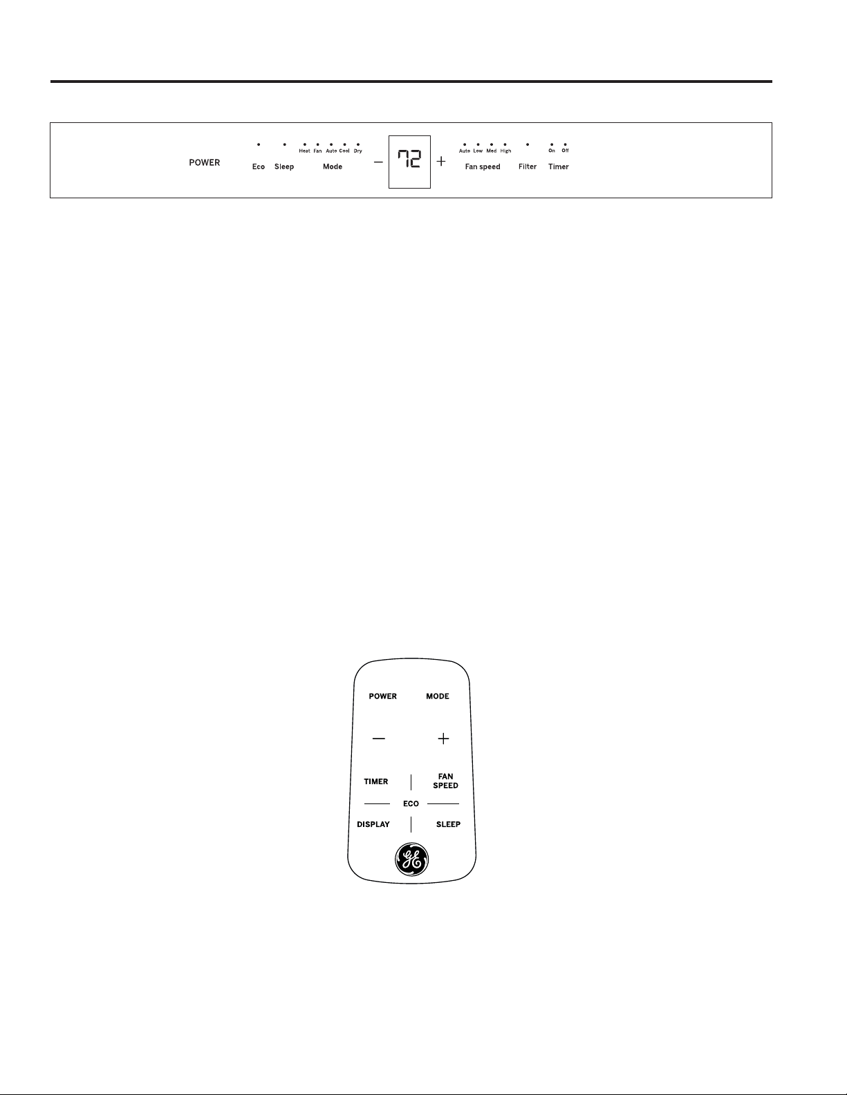
49-5000712 Rev. 1 5
Controles del Acondicionador de Aire
Ŷ3DUDDVHJXUDUXQXVRDSURSLDGRDSXQWHHOFRQWURO
remoto al receptor de señal del acondicionador de
aire.
Ŷ/DVHxDOGHOFRQWUROUHPRWRFXHQWDFRQXQDOFDQFHGH
hasta 21 pies.
Ŷ$VHJ~UHVHGHTXHQDGDVHLQWHUSRQJDHQWUHHO
acondicionador de aire y el control remoto que pudiera
bloquear la señal.
Ŷ$VHJ~UHVHGHTXHODEDWHUtDVHDQXHYD\TXHVH
HQFXHQWUHLQVWDODGDGHIRUPDFRUUHFWDFRQVXOWHOD
sección de Cuidado y Limpieza.
/DDSDULHQFLDSXHGHYDULDU
Control Remoto
/DVOXFHVTXHHVWiQVREUHODVWHFODVWiFWLOHVGHOSDQHOGHFRQWUROGHO
acondicionador de aire indican las configuraciones seleccionadas.
Uso del acondicionador de aire - Controles
USO DEL ACONDICIONADOR DE AIRE
1. POWER (Encendido)
Enciende y apaga el acondicionador de aire.
2. Display (Pantalla)
Exhibe la configuración de temperatura. Muestra las
horas al configurar el temporizador.
3. Mode (Modo)
8VHXWLOL]DSDUDFRQILJXUDUORVPRGRV&22/)UtR
+($7&DORUHQDOJXQRVPRGHORV'5<6HFR$872
$XWRPiWLFRR)$19HQWLODGRU/DVOXFHVLQGLFDGRUDV
de los controles mostrarán el modo seleccionado.
4. Teclas de Incremento + / Reducción – de
Temperatura
Se utiliza para configurar la temperatura en los modos
$XWR$XWRPiWLFR&RRO)UtR'U\6HFRR+HDW&DORU
HQDOJXQRVPRGHORV
5. Fan Speed (Velocidades del ventilador)
Se utiliza para configurar la velocidad del ventilador en
/2:$OWD0(',800HGLDR+,*+$OWD/DVOXFHV
indicadoras mostrarán la velocidad seleccionada.
6. Timer (Temporizador)
ON(1&(1','26HXWLOL]DSDUDFRQILJXUDUHO
acondicionador de aire para que de forma automática se
encienda entre 0.5 y 24 horas más tarde.
OFF$3$*$'2±6HXWLOL]DSDUDDSDJDUHO
acondicionador de aire entre 0.5 y 24 horas más tarde.
7. Filter (Filtro)
Monitorea el tiempo de funcionamiento acumulado del
ventilador como recordatorio de la necesidad de limpiar
el filtro.
8. Eco
ON(1&(1','26HXWLOL]DSDUDGHVDFWLYDUHOFLFORGHO
ventilador cuando finaliza el ciclo del compresor.
OFF$3$*$'26HXWLOL]DSDUDKDFHUIXQFLRQDUHO
ventilador de forma continua cuando se encuentre en el
PRGRGHUHIULJHUDFLyQRFDOHIDFFLyQHQDOJXQRVPRGHORV
9. Sleep (Inactividad)
$OORZVURRPWHPSHUDWXUHWRLQFUHDVH&RROPRGHRU
GHFUHDVH+HDWPRGHGXULQJVOHHSLQJKRXUV
Temp/Timer

6 49-5000712 Rev. 1
Uso del acondicionador de aire - Caracteristicas
USO DEL ACONDICIONADOR DE AIRE
Para Ajustar las Velocidades del Ventilador
Presione el botón Fan Speed para seleccionar la velocidad del
ventilador en cuatro pasos: Auto
/RZ0HGR+LJK&DGDYH]TXH
se presiona el botón, se cambia el modo de velocidad del ventilador
En algunos modelos, la velocidad del ventilador no se puede
DMXVWDUHQHOPRGR+($7(QHOPRGR'5<ODYHORFLGDGGHO
ventilador es controlada en el nivel bajo de forma automática.
Sleep (Función de Inactividad)
Presione el botón Sleep para iniciar el modo de inactividad.
En este modo, la temperatura seleccionada se incrementará
UHIULJHUDFLyQRUHGXFLUiFDOHIDFFLyQHQ)&PLQXWRV
GHVSXpVGHKDEHUVHOHFFLRQDGRHOPRGR/XHJRODWHPSHUDWXUD
VHLQFUHPHQWDUiUHIULJHUDFLyQRUHGXFLUiFDOHIDFFLyQHQRWURV
)&GHVSXpVGHRWURVPLQXWRV
Esta nueva temperatura se mantendrá durante 7 horas antes
de regresar a la temperatura seleccionada originalmente. Esto
finaliza el modo Sleep y la unidad continuará funcionando
como se programó originalmente. El programa del modo Sleep
,QDFWLYLGDGVHSRGUiFDQFHODUHQFXDOTXLHUPRPHQWRGXUDQWH
el funcionamiento, presionando el botón Sleep nuevamente.
Controle la Función del Filtro
Presione el botón Filter para iniciar esta función. Esta función
es un recordatorio de que se debe limpiar el filtro de aire para
un funcionamiento más eficiente.
/DOX]/('VHLOXPLQDUiOXHJRGHKRUDVGHIXQFLRQDPLHQWR
Para realizar el reinicio luego de la limpieza del filtro, presione
el botón Filter y la luz se apagará.
Función de Ahorro de Energía
Presione el botón Eco para iniciar esta función. Esta función
está
GLVSRQLEOHHQORVPRGRV&22/'5<$872
VyORHQ$872
&22/,1*\$872)$1(OYHQWLODGRUFRQWLQXDUi
funcionando
durante 3 minutos una vez que se apague el compresor.
El ventilador luego realizará un ciclo de 2 minutos en intervalos
de 10 minutos, hasta que la temperatura de la sala se encuentre
por encima de la temperatura configurada, momento en el cual el
compresor se enciende y la refrigeración comienza.
Temporizador: Función Auto Start/ Stop (Inicio/ Detención Automática)
Ŷ&XDQGRODXQLGDGVHHQFXHQWUHHQFHQGLGDRDSDJDGDSULPHUR
SUHVLRQHHOERWyQ7LPHU7HPSRUL]DGRU\ODOX]GHOLQGLFDGRU
GH7,0(5217HPSRUL]DGRU(QFHQGLGRVHLOXPLQDUi,QGLFD
TXHHOSURJUDPD$XWR6WDUW,QLFLR$XWRPiWLFRIXHLQLFLDGR
.
Ŷ&XDQGRHOWLHPSRGH7,0(5217HPSRUL]DGRU(QFHQGLGRVHD
H[KLELGRSUHVLRQHHOERWyQ7LPHU7HPSRUL]DGRUQXHYDPHQWH
\ODOX]LQGLFDGRUDGH7,0(52))7HPSRUL]DGRU$SDJDGR
VHLOXPLQDUi,QGLFDTXHHOSURJUDPD$XWR6WRS$SDJDGR
$XWRPiWLFRIXHLQLFLDGR.
Ŷ0DQWHQJDSUHVLRQDGRHOERWyQ83$UULEDR'2:1$EDMR
SDUDFDPELDUHOWLHPSRGH$XWR$XWRPiWLFRSRULQFUHPHQWRV
de 0.5 horas, hasta 10 horas, y luego por incrementos de 1
hora hasta 24 horas. El control realizará una cuenta regresiva
del tiempo restante hasta el inicio
.
Ŷ(OWLHPSRVHOHFFLRQDGRVHUHJLVWUDUiHQVHJXQGRV\HO
sistema volverá automáticamente a exhibir la configuración
de temperatura previa o la temperatura de la sala cuando
ODXQLGDGVHHQFXHQWUHHQFHQGLGD&XDQGRODXQLGDGVH
HQFXHQWUHDSDJDGDQRVHYLVXDOL]DUiODSDQWDOOD
.
Ŷ(QFHQGHURDSDJDUODXQLGDGHQFXDOTXLHUPRPHQWRR
ajustar la configuración del temporizador en 0.0 cancelará el
SURJUDPDFRQWHPSRUL]DGRU$XWR6WDUW6WRS,QLFLR'HWHQFLyQ
$XWRPiWLFD
Para Seleccionar el Modo de Funcionamiento
Para elegir el modo de funcionamiento, presione el botón
Mode. Cada vez que presione el botón, un modo es
seleccionado en una secuencia que se inicia desde Auto,
&RRO'U\+HDWHQDOJXQRVPRGHORV\)DQ~QLFDPHQWH/D
luz indicadora en la parte superior se iluminará y permanecerá
encendida una vez seleccionado el modo.
/DXQLGDGLOXPLQDUiODIXQFLyQ(QHUJ\6DYHUHQORVPRGRV
&RRO'U\$XWRVyOR$XWR&RROLQJ\$XWR)DQ
Para un Funcionamiento en Auto Feature (Función Automática):
Ŷ$OFRQILJXUDUHODFRQGLFLRQDGRUGHDLUHHQHOPRGR$872
, el
mismo seleccionará de forma automática el funcionamiento
HQUHIULJHUDFLyQFDOHIDFFLyQHQDOJXQRVPRGHORVR
ventilación únicamente, dependiendo de qué
temperatura se
haya seleccionado y de la temperatura de la sala.
Ŷ(ODFRQGLFLRQDGRUGHDLUHFRQWURODUiODWHPSHUDWXUDGHODVDODGH
forma automática hasta el punto de configuración de temperatura
.
Ŷ(QHVWHPRGRODYHORFLGDGGHOYHQWLODGRUQRVHSRGUiDMXVWDU
comenzará de forma automática en una velocidad de acuerdo
con la temperatura de la sala.
Para un Funcionamiento en Fan Only (Ventilador Únicamente):
Ŷ8VHHVWDIXQFLyQVyORFXDQGRQRVHGHVHHUHIULJHUDU3XHGH
elegir la velocidad de ventilación que prefiera.
Ŷ'XUDQWHHVWDIXQFLyQODSDQWDOODPRVWUDUiODWHPSHUDWXUDUHDO
de la sala, y no la temperatura configurada en el modo de
refrigeración.
Ŷ(QHOPRGR)DQ2QO\QRHVSRVLEOHDMXVWDUODWHPSHUDWXUD
Para un Funcionamiento en Dry Mode (Modo Seco):
Ŷ(QHVWHPRGRHODFRQGLFLRQDGRUGHDLUHJHQHUDOPHQWH
IXQFLRQDUiHQODIRUPDGHGHVKXPLGLILFDGRU'HELGRDTXH
el espacio acondicionado es un área cerrada o sellada,
continuará habiendo cierto grado de refrigeración.
Fahrenheit vs. Celsius
3DUDFDPELDUODSDQWDOODGHWHPSHUDWXUDGH)DKUHQKHLWD&HOVLXVSUHVLRQH\MXQWRV\PDQWpQJDORVSUHVLRQDGRV
durante 5 segundos.
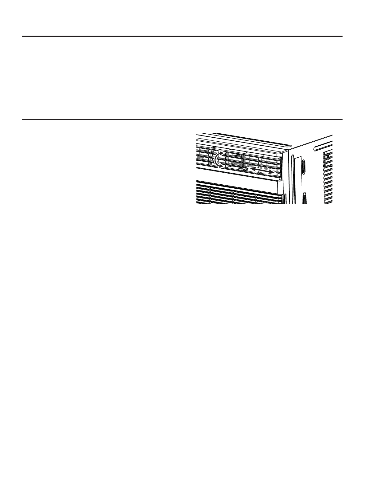
49-5000712 Rev. 1 7
Uso del acondicionador de aire - Caracteristicas
USO DEL ACONDICIONADOR DE AIRE
Funciones Adicionales
(OFLUFXLWR³&RRO´)UtRFXHQWDFRQXQLQLFLRUHWUDVDGR
automático de 3 minutos, si la unidad es apagada y encendida
rápidamente. Esto evita el sobrecalentamiento del compresor y
posibles desconexiones del disyuntor. El ventilador continuará
funcionando durante este tiempo
Hay un retraso de 2 segundos del compresor, el cual se detiene
DOVHOHFFLRQDU)$121/<+($76yOR9HQWLODGRU&DORU(VWR
es para cubrir la posibilidad de tener que girar el selector para
pasar a otro modo.
El control mantendrá la temperatura configurada en
DSUR[LPDGDPHQWH)\HQWUH)\)HQHOPRGRIUtRR
FDORUHQDOJXQRVPRGHORV
/XHJRGHXQFRUWHGHFRUULHQWHODXQLGDGUHFRUGDUiOD~OWLPD
configuración y regresará la unidad a la misma cuando la
corriente se restablezca.
Dirección del Aire
/DVSDOHWDVGHGLUHFFLRQDPLHQWRGHODLUHFRQWURODQODGLUHFFLyQ
del flujo del aire.
/DVSDOHWDVOHSHUPLWLUiQGLULJLUHOIOXMRGHDLUHKDFLDDUULEDR
abajo y hacia la izquierda o derecha a través de la sala, según
sea necesario, hasta que se logre la dirección deseada hacia la
L]TXLHUGDGHUHFKD3LYRWHHODVSDOHWDVKRUL]RQWDOHVKDVWDTXH
VHORJUHODGLUHFFLyQGHVHDGDKDFLDDUULEDDEDMR

49-5000712 Rev. 1
CUIDADO Y LIMPIEZA
Cuidado y Limpieza
Cómo Insertar las Baterías en el Control Remoto
1. Retirez le couvercle de la batterie en faisant glisser la
languette de verrouillage vers la gauche et en tirant le
couvercle de la batterie hors de la télécommande.
,QVHUWHXQDEDWHUtDQXHYDDVHJXUiQGRVHGHTXHHO\HO
±GHODPLVPDHVWpQLQVWDODGRVFRUUHFWDPHQWHKDFLD
arriba.
3. Remettez le couvercle en place en le faisant glisser dans la
télécommande.
NOTAS:
8VHXQDEDWHUtD&59'&1RXVHEDWHUtDV
recargables.
• Retire las baterías del control remoto si el sistema no será
usado por un período de tiempo prolongado.
Bobinas Exteriores
/DVERELQDVGHOODGRH[WHULRUGHODFRQGLFLRQDGRUGHDLUHVH
deberán controlar de forma regular.
• Si se encuentran atascadas con suciedad u hollín, es posible
que la limpieza deba ser realizada por un profesional,
un servicio disponible a través de GE Appliances u otras
empresas de servicios.
Retiro de la Rejilla Frontal
/DUHMLOODIURQWDOSRGUiVHUUHWLUDGDSDUDXQDOLPSLH]DPiVD
fondo.
Para retirar:
1. Tome los laterales de la rejilla frontal desde las áreas libres
a cada lado e incline la misma hacia adelante.
2. Retire el filtro empujando el mismo hacia adelante y afuera.
3. Retire los dos tornillos con cabeza Phillips ubicados en las
esquinas superiores de la rejilla.
4. Empuje hacia adentro a cada lado de la tapa del chasis
metálico, aproximadamente a 5” desde la parte inferior.
Esto liberará las lengüetas de la rejilla de la tapa del chasis
metálico. Empuje la parte inferior de la rejilla levemente
hacia adelante, mientras levanta la rejilla hacia arriba.
8QDYH]OLEHUDGDODUHMLOODGHIRUPDVXDYHOHYDQWHODPLVPD
para liberar las lengüetas de la parte superior de la tapa del
chasis metálico.
6. A fin de liberar el conector eléctrico de clavijas múltiples
desde la interface del usuario, presione ambos lados y
suavemente realice el desmontaje.
Invierta el orden para volver a instalar la rejilla.
Filtro de Aire
Para acceder al filtro, tome la rejilla frontal sobre ambos lados
del espacio libre y realice la inclinación hacia adelante. Retire
HOILOWUROHYDQWDQGRHOPLVPRKDFLDDUULED\DIXHUD2EVHUYHOD
dirección del filtro al volver a realizar la instalación.
/DYHHOILOWURXVDQGRGHWHUJHQWHOtTXLGRSDUDODYDYDMLOODV\DJXD
FDOLHQWH(QMXDJXHHOILOWURFRPSOHWDPHQWH'HIRUPDVXDYH
sacuda el exceso de agua del filtro.
Asegúrese de que el filtro esté totalmente seco antes de su
UHHPSOD]R2HQFDPELRSRGUiDVSLUDUHOILOWURKDVWDTXH
quede limpio.
NOTA:1XQFDXVHDJXDFDOLHQWHFRQXQDWHPSHUDWXUDVXSHULRU
D)&SDUDOLPSLDUHOILOWURGHDLUH1XQFDLQWHQWHXVDU
la unidad sin el filtro de aire.
Nota sobre Ahorro de Energía
A fin de lograr el máximo ahorro de energía y confort, se
recomienda el uso de una tapa para aislar la unidad cuando
la misma no se encuentre en uso. El tamaño de la tapa
UHFRPHQGDGRHVGH´[´[´$QFKR[$OWR['LiP
NOTE:'HVHQFKXIHODXQLGDGDQWHVGHLQVWDODUXQDWDSD
Gabinete
• Asegúrese de desenchufar el acondicionador de aire para
evitar cortocircuitos o riesgos de incendio. El gabinete y el
frente se podrán limpiar con una tela libre de aceite o lavada
con una tela humedecida en una solución de agua caliente
y detergente para lavavajillas líquido suave. Enjuague
completamente con una tela húmeda y luego seque.
1XQFDXVHOLPSLDGRUHVDEUDVLYRVFHUDRSXOLGRUVREUHHO
frente del gabinete.
• Asegúrese de escurrir el exceso de agua de la tela antes de
realizar la limpieza alrededor de los controles. El exceso de
agua en o alrededor de los controles podrá generar daños
sobre el acondicionador de aire.
• Enchufe el acondicionador de aire.
49-5000712 Rev. 1 9
Instrucciones de Instalación
INSTRUCCIONES DE INSTALACIÓN
Para acceder a más ayuda, visite GEAppliances.com
Para Carcasas de Pared Existentes
2EVHUYHTXHODVGLPHQVLRQHVGHODFRQGLFLRQDGRUGHDLUH
VRQ´GHDQFKR´GHDOWR\´GHSURIXQGLGDGVLQ
IUHQWH,QVWDOHHODFRQGLFLRQDGRUGHDLUHGHDFXHUGRFRQ
estas instrucciones de instalación para lograr el mejor
rendimiento. Guarde estas instrucciones de instalación para
referencia futura.
NOTA:1RXVHQLQJ~QWRUQLOORH[FHSWRDTXHOORV
especificados aquí.
Piezas Incluidas
(VSRVLEOHTXHQRQHFHVLWHWRGDVODVSLH]DVGHONLW'HVFDUWH
las piezas no utilizadas.
1RPEUH Especif. Cant.
Bloques espaciadores cónicos 17” de longitud 2
%ORTXHVGH6RSRUWH&HQWUDGR ´[´[´ 4
'LYLVRUGH3OiVWLFR ´[´[´ 2
Junta de Relleno ´[´[´ 1
Junta ´[´[´ 3
Junta ´[´[´ 2
Junta ´[´[´ 3
Junta ´[´[´ 2
Junta 2
(VWUXFWXUD$MXVWDEOHSDWDV
ODWHUDOHV
2
(VWUXFWXUD$MXVWDEOHSDWDV
VXSHULRUHVHLQIHULRUHV
2
&DEOHD7LHUUDYHUGH 1
$UDQGHOD'HQWDGDSDUDWRUQLOOR
a tierra
2
Tornillo a Tierra 1
5HMLOOD3OiVWLFR 1
5HMLOOD$OXPLQLR 1
7XHUFDV3OiVWLFR 4
Arandela de Tornillo 4
Tornillo 4
Soportes de Seguridad para
&DUFDVDGH3DUHGGH´HQ
un paquete separado con sus
WRUQLOORVGHPRQWDMH
2
Soportes de Seguridad para
&DUFDVDGH3DUHGGH´HQ
un paquete separado con sus
WRUQLOORVGHPRQWDMH
2
NOTA IMPORTANTE
Para una óptima eficiencia y rendimiento energético, le
recomendamos el uso de la Carcasa de Pared RAB24 y la
rejilla exterior de aluminio estampado o la RAB26A con la
rejilla exterior de aluminio estampado RAG13.
ANTES DE INICIAR
Lea estas instrucciones completa y
cuidadosamente.
•
IMPORTANTE – Guarde estas
instrucciones para uso del inspector local.
•
IMPORTANTE – 2EVHUYHWRGRVORV
códigos y órdenes de ley.
• Nota al instalador ±$VHJ~UHVHGHGHMDUHVWDV
instrucciones con el consumidor.
• Nota al consumidor ±&RQVHUYHHVWDVLQVWUXFFLRQHV
para referencia futura..
• Nivel de destreza±/DLQVWDODFLyQGHHVWHDSDUDWR
requiere de destrezas mecánicas básicas.
• Tiempo de ejecución – Aprox. 1 hora
• Recomendamos dos personas para la instalación de
este producto.
/DLQVWDODFLyQDSURSLDGDHVODUHVSRQVDELOLGDGGHO
instalador.
/DIDOODGHOSURGXFWRGHELGRDXQDLQVWDODFLyQ
inadecuada no está cubierta por la garantía.
&XDQGRLQVWDOHHVWHDFRQGLFLRQDGRUGHDLUH'(%(XVDU
todas las piezas suministradas y usar procedimientos
adecuados de instalación.
REQUISITOS ELÉCTRICOS
El cable de corriente incluye un interruptor de corriente. Se
brinda un botón de TEST(YDOXDFLyQ\RESET5HLQLFLR
en la caja del enchufe. El dispositivo deberá ser evaluado
en forma periódica, presionando primero el botón TEST
(YDOXDU\OXHJRRESET5HLQLFLRPLHQWUDVVHHQFXHQWUH
enchufado al tomacorriente. Si el botón TEST(YDOXDU
no se activa o el botón RESET5HLQLFLRQRSHUPDQHFH
en su posición, deje de usar el acondicionador de aire y
comuníquese con un técnico calificado del servicio.
PRECAUCIÓN
Bajo ninguna circunstancia corte o remueva la tercera
S~DFRQH[LyQDWLHUUDGHOFDEOHHOpFWULFR
1RFDPELHHOHQFKXIHHQHOFDEOHHOpFWULFRGHHVWH
acondicionador de aire.
/RVFDEOHVFDVHURVGHDOXPLQLRSRGUtDQSUHVHQWDU
problemas especiales. Consulte a un técnico electricista
calificado.
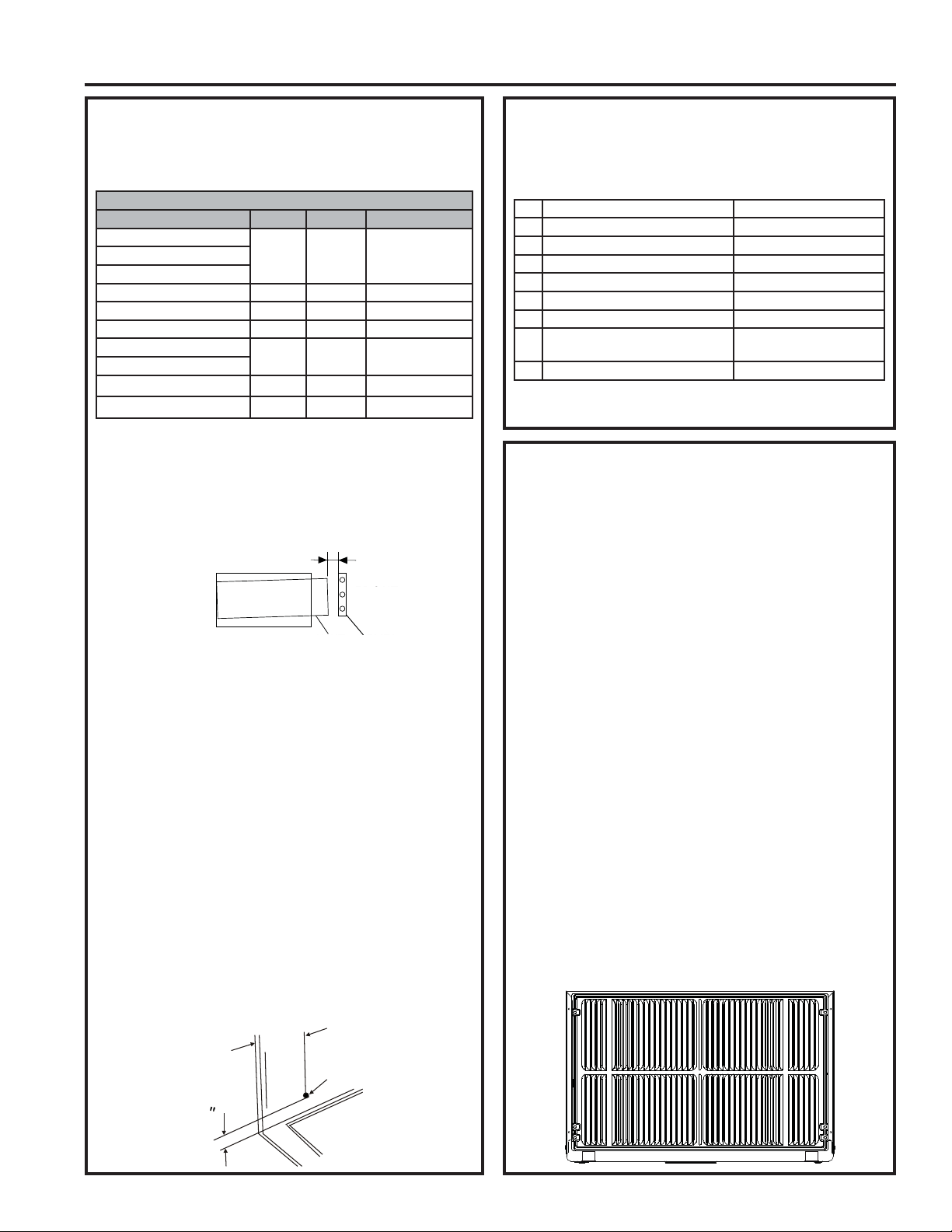
10 49-5000712 Rev. 1
INSTRUCCIONES DE INSTALACIÓN
Instrucciones de Instalación
Cómo Realizar la Instalación en una
Carcasa de Pared Preexistente
1. Identifique la marca de la carcasa de pared para su
instalación, desde el cuadro inferior.
'LPHQVLRQHVGHOD&DUFDVDGH3DUHGSXOJDGDV
Ancho Altura Profundidad
:KLWH:HVWLQJKRXVH
RU
Frigidaire
&DUULHU6HULH)
*(+RWSRLQW 26
Whirlpool RU
)HGGHUV(PHUVRQ 27 RU
6HDUV.HQPRUH
&DUULHU6HULH6
(PHUVRQ)HGGHUV 15
Friedrich 27
NOTA: Todas las carcasas de pared usadas para montar
el nuevo acondicionador de aire deberán estar en buenas
condiciones estructurales y contar con una rejilla trasera que
se adhiera de forma segura a la carcasa, o a la brida trasera
que sirve como detención del acondicionador de aire.
IMPORTANTE:8QDYH]FRPSOHWDGDODLQVWDODFLyQODXQLGDG
GHUHHPSOD]R'(%(5ÈSRVHHUXQDSHQGLHQWHKDFLDDWUiV
como se muestra.
2. Retire el antiguo acondicionador de aire de la carcasa de
pared y prepare esta última del siguiente modo:
Ŷ/LPSLHHOLQWHULRUQRDOWHUHODVMXQWDV
Ŷ
/DFDUFDVDGHSDUHGVHGHEHUiDMXVWDUGHIRUPDVHJXUD
en una pared antes de instalar el acondicionador de aire.
Coloque más clavos o tornillos a través de la carcasa, en
la pared, de ser necesario
.
Ŷ5HSDUHODSLQWXUDGHVHUQHFHVDULR
3.
'HQRH[LVWLUSUHYLDPHQWHSHUIRUHXQDJXMHURGH´
para adherir el cable de conexión a tierra suministrado
VREUHHOODGRL]TXLHUGRGHODFDUFDVDGHSDUHGFRQVXOWH
las dimensiones aproximadas de la ubicación del agujero
HQODVLJXLHQWHLOXVWUDFLyQ8VHODDUDQGHODGHQWDGD\
el tornillo con punta para adherir un extremo del cable a
tierra verde suministrado en el interior de la carcasa de
SDUHG/DDUDQGHODGHQWDGDVHGHEHUiHQFRQWUDUHQWUHHO
agujero pequeño del cable y la carcasa de pared. TENGA
CUIDADO DE NO AJUSTAR EN EXCESO EL TORNILLO.
Empuje y deje el extremo del cable a tierra suelto sobre el
frente de la carcasa, y de forma temporaria doble el mismo
hacia abajo y alrededor del extremo inferior de la carcasa.
Este cable a tierra luego será ajustado al marco del
acondicionador de aire una vez instalado.
Cómo Realizar la Instalación en una
Carcasa de Pared Preexistente (continúa)
4.
Prepare la carcasa de pared para la instalación de la nueva
unidad de acuerdo con las siguientes instrucciones por marca.
1 Emerson Profundidad de 15”
2 Fedders Profundidad de 19 ¾”
3 Fedders or Friedrich 3URIXQGLGDGGH´
4 *(+RWSRLQW 3URIXQGLGDGGH´
5 Sears or Carrier 6HULH6 3URIXQGLGDGGH´
6 Whirlpool 3URIXQGLGDGGH´
7 Whirlpool Profundidad de 23”
:KLWH:HVWLQJKRXVH
)ULJLGDLUH&DUULHU6HULH)
3URIXQGLGDGGH´
´
9 :KLWH:HVWLQJKRXVH)ULJLGDLUH Profundidad de 22”
5. Identifique su tipo de carcasa de pared y siga las
instrucciones para dicho tipo en las siguientes páginas.
IMPORTANTE - ANTES DE INICIAR
Ŷ/DVFDUDFWHUtVWLFDVGHUHQGLPLHQWRGHHVWDXQLGDGVRQHO
resultado de contar con dos entradas de aire traseras.
Ŷ(VPX\LPSRUWDQWHTXHHVWDVLQVWUXFFLRQHVVHVLJDQGH
modo que su unidad pueda funcionar en el máximo nivel
de eficiencia.
ŶSi se trata de una carcasa existente, y hay una rejilla trasera
existente, es posible que la misma deba ser reemplazada
por una que haya sido enviada con la unidad en el kit de
accesorios. Si la rejilla trasera nueva es demasiado pequeña
para la abertura de la carcasa trasera, utilice la rejilla de plástico
negra. Cerciórese de que esté asegurada en su posición
usando los tornillos, arandelas y arandelas aislantes incluidas.
PARA UN MAYOR NIVEL DE EFICIENCIA, UTILICE EL
PANEL DE CELOSÍA TRASERO PROVISTO
Instalación de una nueva rejilla provista con la unidad.
5HWLUHODUHMLOODH[LVWHQWH([FHSFLyQ*(´
2. Coloque la rejilla, incluida con el nuevo acondicionador
de aire, hacia la parte trasera de la carcasa.
3. Realice una marca sobre las posiciones de los agujeros.
3HUIRUHODVEULGDVGHODVFDUFDVDVFRQXQDEURFDGH´
5. Adhiera la nueva rejilla con tornillos autorroscantes y
arandelas.
(V08<,03257$17(TXHODUHMLOODVHDFRORFDGD
exactamente como se muestra a continuación.
/DPD\RUtDGHODVUHMLOODVGHFRUDWLYDVH[WHULRUHVVH
podrán dejar en su posición, siempre y cuando se instale
la rejilla interior de direccionamiento de aire correcta.
REAR
Wall Sleeve
UNIT
LEVEL
FRONT
to
3
Carcasa de Pared
PARTE
TRASERA
)5(17(
1,9(/81,'$'
j´
1
Agujero
GH´
Máx.
de 3”
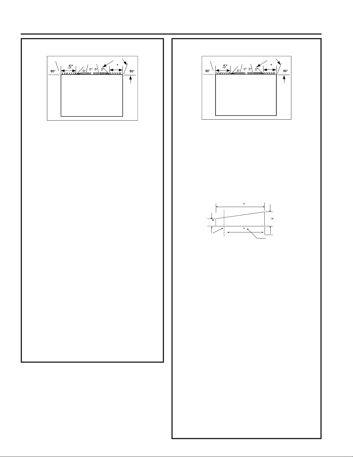
49-5000712 Rev. 1 11
Instrucciones de Instalación
INSTRUCCIONES DE INSTALACIÓN
Emerson (Profundidad de 15”)
4
4
3
8
3
8
1. Retire la rejilla trasera existente como se muestra en la
página 9 de este manual y reemplace la misma por el
panel trasero con celosía provisto.
NOTA: Es posible que necesite perforar agujeros sobre
la brida de la carcasa existente para que coincidan con la
nueva rejilla trasera.
$GKLHUDMXQWDODUJDGH´[´[´HQHOFHQWURGHOD
parte superior de la carcasa. Retire el papel de soporte y
presione el mismo hasta su posición.
$GKLHUDMXQWDVODUJDVGH´[´[´HQORV
costados izquierdo y derecho de la carcasa.
&RUWHMXQWDVGH´[´[´HQXQDORQJLWXGGH´\
adhiera las mismas sobre las secciones verticales de la
rejilla trasera.
$GKLHUDEORTXHVGHVRSRUWHFHQWUDGRGH´[
´[´XQRDFDGDODGRGHODSDUHG&RORTXHORV
mismos en el centro de la pared lateral con el extremo
cónico hacia la abertura.
'HIRUPDVXDYHGHVOLFHODXQLGDGVREUHODFDUFDVD
7. Antes de deslizar la misma completamente hacia atrás,
retire el segundo tornillo del frente del lado izquierdo de la
unidad.
5HWLUHODDUDQGHODGHSOiVWLFRGHOWRUQLOOR
9. Atornille y adhiera el otro extremo del cable a tierra a
la unidad. Asegúrese de que la arandela dentada se
encuentre contra el gabinete.
'HVOLFHODXQLGDGFRPSOHWDPHQWHVREUHODSDUWHWUDVHUDD
fin de contar con un buen sellado, asegurándose de que
el cable a tierra no quede enredado.
11. Si tiene dificultades con el montaje de la rejilla sobre la
carcasa, siga las instrucciones para un montaje directo
en la página 16.
12. Selle y enmarque la unidad como se describe en la
página 17.
Fedders (Profundidad de 19-3/4”)
4
4
3
8
3
8
1. Retire la rejilla trasera existente como se muestra en la
página 9 de este manual y reemplace la misma por el
panel trasero con celosía provisto.
NOTA: Es posible que necesite perforar agujeros sobre
la brida de la carcasa existente para que coincidan con la
nueva rejilla trasera.
$GKLHUDEORTXHVGHVRSRUWHFHQWUDGRGH´[´
[´XQRDFDGDODGRGHODSDUHG&RORTXHORVPLVPRV
en el centro de la pared lateral con el extremo cónico
hacia la abertura.
3. Recorte 2 bloques espaciadores cónicos de 17” como se
muestra a continuación en dos piezas.
/DVHFFLyQGH´VHHQFXHQWUDFRORFDGDIUHQWHDODEDVH
de apoyo con el extremo cónico enfrentado hacia la parte
WUDVHUDGHODFDUFDVD/DSDUWHUHVWDQWHVHUiFRORFDGD
detrás de la base de apoyo nuevamente con la pendiente
hacia la parte trasera de la carcasa. Esto ayuda a inducir
una pendiente hacia atrás sobre la unidad.
$GKLHUDMXQWDODUJDGH´[´[´HQHOFHQWURGHOD
parte superior de la carcasa. Retire el papel de soporte y
presione el mismo hasta su posición.
$GKLHUDMXQWDVGH´[´[´HQORVFRVWDGRV
izquierdo y derecho de la carcasa.
&RUWHMXQWDVGH´[´[´HQXQDORQJLWXGGH´\
adhiera las mismas sobre las secciones verticales de la
rejilla trasera.
'HIRUPDVXDYHGHVOLFHODXQLGDGVREUHODFDUFDVD
9. Antes de deslizar la misma completamente hacia atrás, retire
el segundo tornillo del frente del lado izquierdo de la unidad.
10. Retire la arandela de plástico del tornillo.
11. Atornille y adhiera el otro extremo del cable a tierra a
la unidad. Asegúrese de que la arandela dentada se
encuentre contra el gabinete.
'HVOLFHODXQLGDGFRPSOHWDPHQWHVREUHODSDUWHWUDVHUDD
fin de contar con un buen sellado, asegurándose de que
el cable a tierra no quede enredado.
13. Si tiene dificultades con el montaje de la rejilla sobre la
carcasa, siga las instrucciones para un montaje directo
en la página 16.
14. Selle y enmarque la unidad como se describe en la
página 17.
9LVWD6XSHULRU
Celosías Traseras
9LVWD6XSHULRU
Celosías Traseras
Cut Here
3
/
4
17
Tapered Spacer Block
1
Protection Paper
4
Cortar Aquí
Soporte del papel
de protección
Bloque Espaciador Cónico
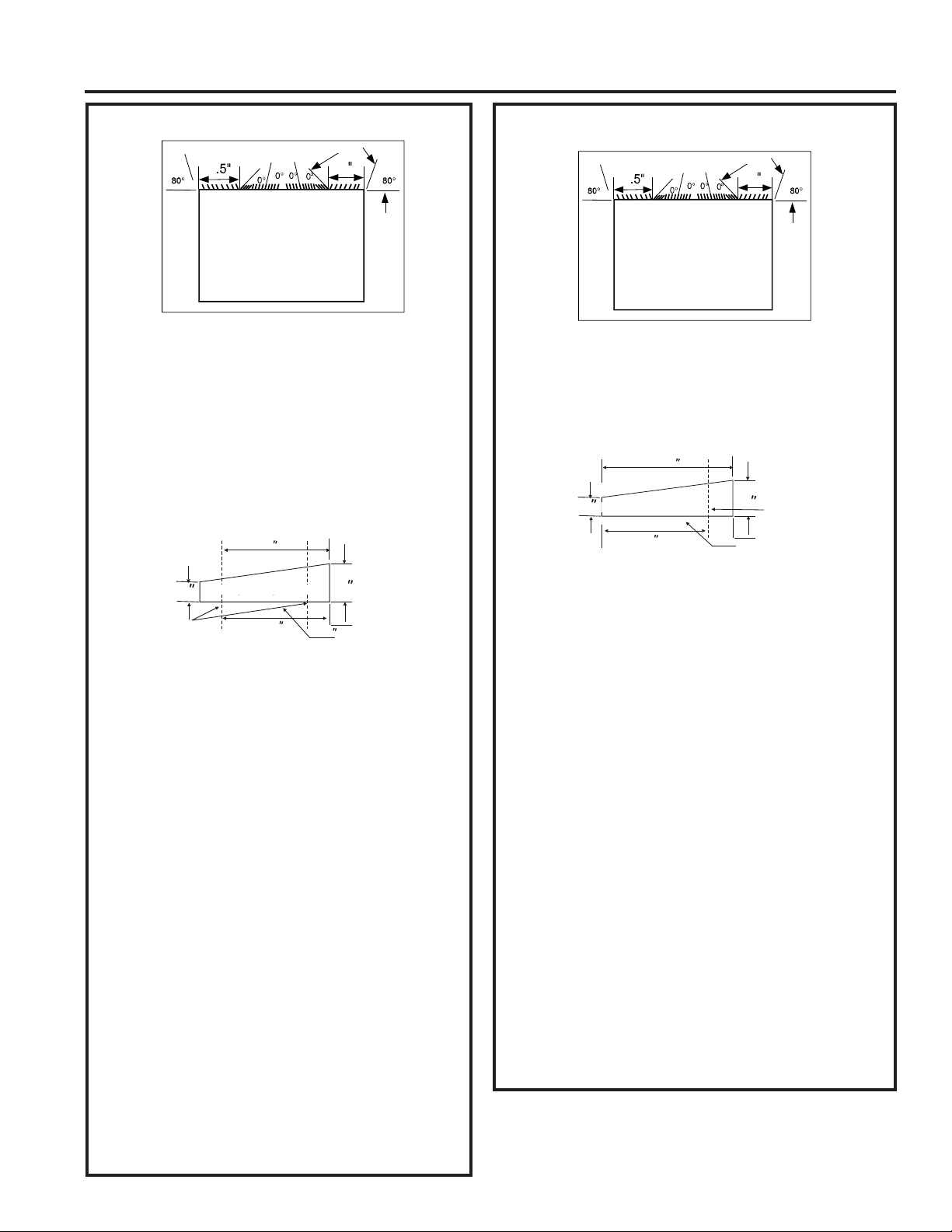
12 49-5000712 Rev. 1
INSTRUCCIONES DE INSTALACIÓN
Instrucciones de Instalación
Fedders o Friedrich (Prof. de 16-3/4”)
1. Retire la rejilla trasera existente como se muestra en la
página 9 de este manual y reemplace la misma por el
panel trasero con celosía provisto.
NOTA: Es posible que necesite perforar agujeros sobre
la brida de la carcasa existente para que coincidan con la
nueva rejilla trasera.
$GKLHUDEORTXHVGHVRSRUWHFHQWUDGRGH´[´
[´XQRDFDGDODGRGHODSDUHG&RORTXHORVPLVPRV
en el centro de la pared lateral con el extremo cónico hacia
la abertura.
3. Recorte 2 bloques espaciadores cónicos de 17” como se
muestra a continuación en tres piezas.
/DVHFFLyQGHò´VHHQFXHQWUDFRORFDGDIUHQWHDODEDVHGH
apoyo con el extremo cónico enfrentado hacia la parte trasera
GHODFDUFDVD5HFRUWHODSDUWHUHVWDQWHGHò´\FRORTXH
la misma detrás de la base de apoyo nuevamente con la
pendiente hacia la parte trasera de la carcasa. Esto ayuda a
inducir una pendiente hacia atrás sobre la unidad.
$GKLHUDMXQWDODUJDGH´[´[´HQHOFHQWURGHOD
parte superior de la carcasa. Retire el papel de soporte y
presione el mismo hasta su posición.
$GKLHUDMXQWDVGH´[´[´HQORVFRVWDGRV
izquierdo y derecho de la carcasa.
&RUWHMXQWDVGH´[´[´HQXQDORQJLWXGGH´\
adhiera los mismos sobre las secciones verticales de la
rejilla trasera
.
'HIRUPDVXDYHGHVOLFHODXQLGDGVREUHODFDUFDVD
9. Antes de deslizar la misma completamente hacia atrás, retire
el segundo tornillo del frente del lado izquierdo de la unidad.
10. Retire la arandela de plástico del tornillo.
11. Atornille y adhiera el otro extremo del cable a tierra a
la unidad. Asegúrese de que la arandela dentada se
encuentre contra el gabinete.
'HVOLFHODXQLGDGFRPSOHWDPHQWHVREUHODSDUWHWUDVHUD
a fin de contar con un buen sellado, asegurándose de que el
cable a tierra no quede enredado.
13. Si tiene dificultades con el montaje de la rejilla sobre
la carcasa, siga las instrucciones para un montaje
directo en la página 16.
14. Selle y enmarque la unidad como se describe en la
página 17.
GE/Hotpoint (Profundidad de 16-7/8”)
4
4
3
8
3
8
1. Conservar la parrilla trasera existente.
8WLOL]DQGRSLQ]DVSXQWDGHDJXMDPRGLILTXHODVSDOHWDV
direccionales de la rejilla exterior de acuerdo con la
ilustración.
3. Recorte 2 bloques espaciadores cónicos de 17” como se
muestra a continuación en dos piezas.
,QVWDOHODVHFFLyQGH´FRQHOH[WUHPRFyQLFRGHò´
desde la parte trasera de la carcasa. Esto ayuda a inducir
una pendiente hacia atrás sobre la unidad.
$GKLHUDMXQWDODUJDGH´[´[´HQHOFHQWURGHOD
parte superior de la carcasa. Retire el papel de soporte y
presione el mismo hasta su posición.
$GKLHUDMXQWDVGH´[´[´HQORVFRVWDGRV
izquierdo y derecho de la carcasa.
&RUWHMXQWDVGH´[´[´HQXQDORQJLWXGGH´\
adhiera las mismas sobre las secciones verticales de la
rejilla trasera.
&HQWUHODXQLGDG\GHIRUPDVXDYHGHVOLFHODXQLGDGHQOD
carcasa.
9. Antes de deslizar la misma completamente hacia atrás,
retire el segundo tornillo del frente del lado izquierdo de la
unidad.
10. Retire la arandela de plástico del tornillo.
11. Atornille y adhiera el otro extremo del cable a tierra a
la unidad. Asegúrese de que la arandela dentada se
encuentre contra el gabinete.
'HVOLFHODXQLGDGFRPSOHWDPHQWHVREUHODSDUWHWUDVHUDD
fin de contar con un buen sellado, asegurándose de que
el cable a tierra no quede enredado.
13. Si tiene dificultades con el montaje de la rejilla sobre la
carcasa, siga las instrucciones para un montaje directo
en la página 16.
14. Selle y enmarque la unidad como se describe en la
página 17.
4
4
3
8
3
8
9LVWD6XSHULRU
Celosías Traseras
9LVWD6XSHULRU
Celosías Traseras
Cut Here
3
/
4
17
Tapered Spacer Block
1
Protection Paper
Backing
12-1/2
2-1/2
Cortar Aquí
Soporte del papel
de protección
Bloque Espaciador Cónico
3
/
4
17
Tapered Spacer Block
1
Protection Paper
Backing
Cut Here
13
Cortar Aquí
Soporte del papel
de protección
Bloque Espaciador Cónico
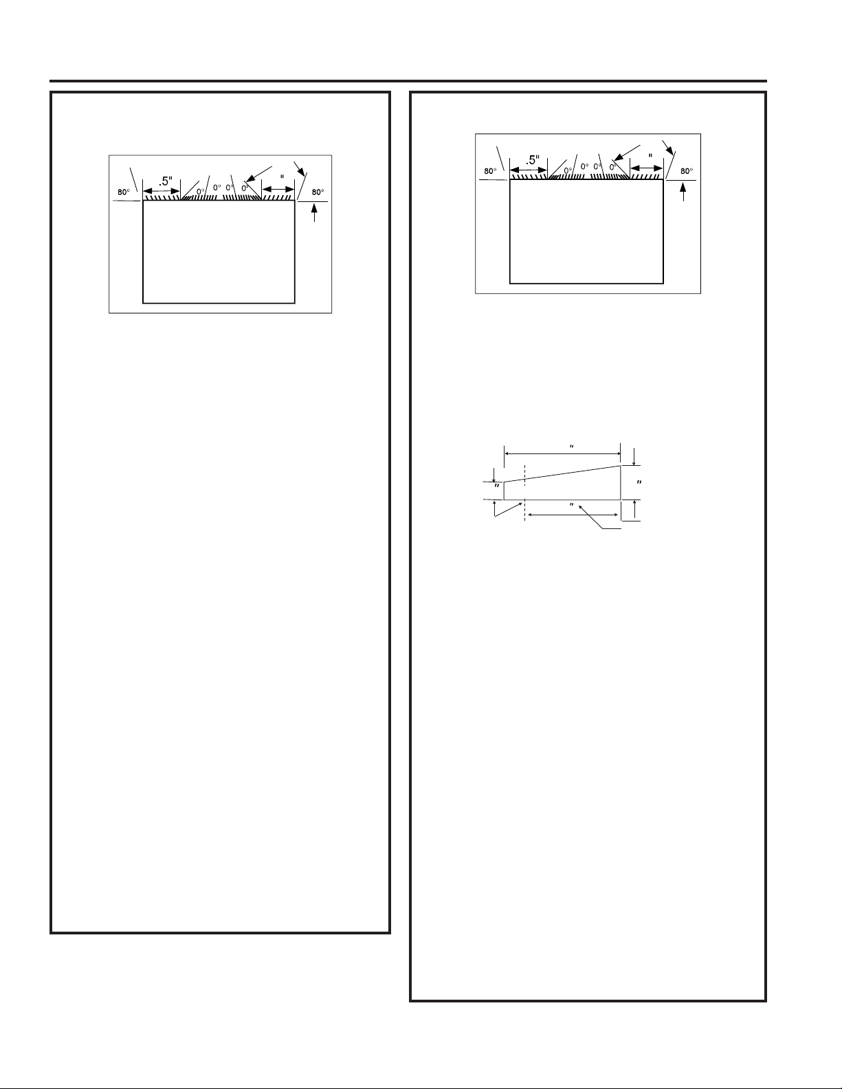
49-5000712 Rev. 1 13
Instrucciones de Instalación
INSTRUCCIONES DE INSTALACIÓN
Sears o Carrier Serie 51S
(Profundidad de 18-5/8”)
4
4
3
8
3
8
1. Retire la rejilla trasera existente como se muestra en la
página 9 de este manual y reemplace la misma por el
panel trasero con celosía provisto.
NOTA: Es posible que necesite perforar agujeros sobre
la brida de la carcasa existente para que coincidan con la
nueva rejilla trasera.
2. Instale 2 bloques espaciadores cónicos al piso de la
carcasa. Esto ayuda a inducir una pendiente hacia atrás
sobre la unidad.
5HDOLFHODLQVWDODFLyQFRQHOH[WUHPRFyQLFRGHò´GHVGH
la parte trasera de la carcasa. Esto ayuda a inducir una
pendiente hacia atrás sobre la unidad.
$GKLHUDMXQWDODUJDGH´[´[´HQHOFHQWURGHOD
parte superior de la carcasa. Retire el papel de soporte y
presione el mismo hasta su posición.
$GKLHUDMXQWDVGH´[´[´HQORVFRVWDGRV
izquierdo y derecho de la carcasa.
&RUWHMXQWDVGH´[´[´HQXQDORQJLWXGGH´\
adhiera las mismas sobre las secciones verticales de la
rejilla trasera.
7. Centre la unidad y de forma suave deslice la unidad en la
carcasa.
$QWHVGHGHVOL]DUODPLVPDFRPSOHWDPHQWHKDFLDDWUiV
retire el segundo tornillo del frente del lado izquierdo de la
unidad.
9. Retire la arandela de plástico del tornillo.
10. Atornille y adhiera el otro extremo del cable a tierra a
la unidad. Asegúrese de que la arandela dentada se
encuentre contra el gabinete.
'HVOLFHODXQLGDGFRPSOHWDPHQWHVREUHODSDUWHWUDVHUDD
fin de contar con un buen sellado, asegurándose de que
el cable a tierra no quede enredado.
12. Si tiene dificultades con el montaje de la rejilla sobre la
carcasa, siga las instrucciones para un montaje directo
en la página 16.
13. Selle y enmarque la unidad como se describe en la
página 17.
Whirlpool (Profundidad de 17-1/8”)
4
4
3
8
3
8
1. Retire la rejilla trasera existente como se muestra en la
página 9 de este manual y reemplace la misma por el
panel trasero con celosía provisto.
NOTA: Es posible que necesite perforar agujeros sobre
la brida de la carcasa existente para que coincidan con la
nueva rejilla trasera.
2. Recorte 2 bloques espaciadores cónicos de 17” como se
muestra a continuación en dos piezas.
3. Instale la sección de 13” al piso de la carcasa. Esto ayuda
a inducir una pendiente hacia atrás sobre la unidad.
$GKLHUDMXQWDODUJDGH´[´[´HQHOFHQWURGHOD
parte superior de la carcasa. Retire el papel de soporte y
presione el mismo hasta su posición.
$GKLHUDMXQWDVGH´[´[´HQORVFRVWDGRV
izquierdo y derecho de la carcasa.
&RUWHMXQWDVGH´[´[´HQXQDORQJLWXGGH´\
adhiera los mismos sobre las secciones verticales de la
rejilla trasera.
7. Centre la unidad y de forma suave deslice la unidad en la
carcasa.
$QWHVGHGHVOL]DUODPLVPDFRPSOHWDPHQWHKDFLDDWUiV
retire el segundo tornillo del frente del lado izquierdo de la
unidad.
9. Retire la arandela de plástico del tornillo.
10. Atornille y adhiera el otro extremo del cable a tierra a
la unidad. Asegúrese de que la arandela dentada se
encuentre contra el gabinete.
'HVOLFHODXQLGDGFRPSOHWDPHQWHVREUHODSDUWHWUDVHUDD
fin de contar con un buen sellado, asegurándose de que
el cable a tierra no quede enredado.
12. Si tiene dificultades con el montaje de la rejilla sobre la
carcasa, siga las instrucciones para un montaje directo
en la página 16.
13. Selle y enmarque la unidad como se describe en la
página 17.
9LVWD6XSHULRU
Celosías Traseras
9LVWD6XSHULRU
Celosías Traseras
3
/
4
17
Tapered Spacer Block
1
Protection Paper
Backing
Cut Here
13
Cortar Aquí
Soporte del Papel
de Protección
Bloque Espaciador Cónico
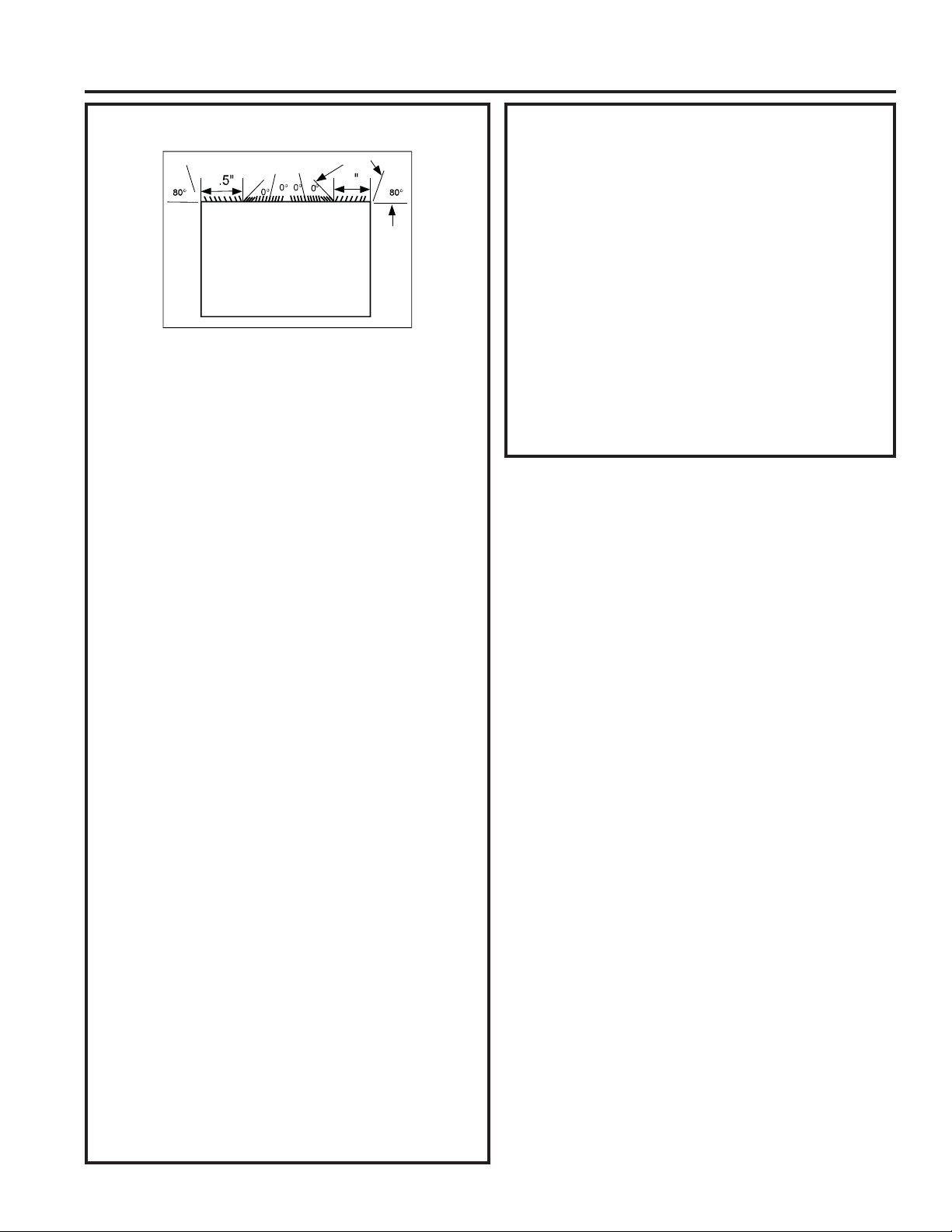
14 49-5000712 Rev. 1
INSTRUCCIONES DE INSTALACIÓN
Instrucciones de Instalación
Whirlpool (Profundidad de 23”)
4
4
3
8
3
8
1. Retire la rejilla trasera existente como se muestra en la
página 9 de este manual y reemplace la misma por el
panel trasero con celosía provisto.
NOTA: Es posible que necesite perforar agujeros sobre
la brida de la carcasa existente para que coincidan con la
nueva rejilla trasera.
Debido al incremento de profundidad en la unidad,
primero intente realizar el montaje en seco utilizando el
método descripto a continuación:
&RORTXHMXQWDVGH´[´[´FRQWUDFDGDODGR
'HIRUPDVXDYHGHVOLFHODXQLGDGKDFLDDGHQWUR\FRQWUROH
que la cantidad que se extiende desde la carcasa sea
suficiente una vez que la estructura de terminación sea
adherida.
4. Si la posición es correcta, retire la unidad y proceda al
siguiente paso. En caso contrario, vaya al Paso 9.
$GKLHUDMXQWDODUJDGH´[´[´HQHOFHQWURGHOD
parte superior de la carcasa. Retire el papel de soporte y
presione el mismo hasta su posición.
$GKLHUDMXQWDVGH´[´[´HQORVFRVWDGRV
izquierdo y derecho de la carcasa.
&RUWHMXQWDVGH´[´[´HQXQDORQJLWXGGH´\
adhiera los mismos sobre las secciones verticales de la
rejilla.
,QVWDOHORVEORTXHVHVSDFLDGRUHVFyQLFRVDOSLVRGHOD
carcasa. Ahora vaya al Paso 15.
Si la unidad requiere una extensión adicional en la sala,
consulte los siguientes pasos:
$GKLHUDODMXQWDODUJDGH´[´[´VREUHODSDUWH
vertical sólida de la rejilla trasera.
$GKLHUDEORTXHVGHJRPDHVSXPDGH´[´[
´FRQODUDQXUDVXSHUSXHVWDFRQODMXQWDTXHHVWi
arriba.
11. Instale el divisor en las ranuras de los bloques de
gomaespuma. Es posible que necesite recortar la
longitud hasta la medida.
5HSHDWVWHSVIRUWKHRWKHUYHUWLFDOSRUWLRQRIWKH
grille.
$GKLHUDMXQWDVGH´[´[´DORVFRVWDGRVGH
la manga nuevamente asegurándose de que todas las
juntas estén nivelados.
&RUWHODMXQWDGH´[ò[SDUDTXHFDOFHFRQOD
SDUWHVXSHULRUGHODFDUFDVD/DVSLH]DVVHGHEHUiQ
ajustar de forma nivelada al extremo del divisor.
Whirlpool (Prof. de 23”) (continúa)
15. Centre la unidad y de forma suave deslice la unidad en
la carcasa.
16. Antes de deslizar la misma completamente hacia atrás,
retire el primer tornillo del frente sobre el lado izquierdo
de la unidad.
17. Retire la arandela de plástico del tornillo.
$WRUQLOOH\DGKLHUDHORWURH[WUHPRGHOFDEOHDWLHUUDD
la unidad. Asegúrese de que la arandela dentada se
encuentre contra el gabinete.
'HVOLFHODXQLGDGFRPSOHWDPHQWHVREUHODSDUWHWUDVHUD
a fin de contar con un buen sellado, asegurándose de
que el cable a tierra no quede enredado.
20. Si tiene dificultades con el montaje de la rejilla sobre la
carcasa, siga las instrucciones para un montaje directo
en la página 16.
21. Selle y enmarque la unidad como se describe en la
página 17.
9LVWD6XSHULRU
Celosías Traseras
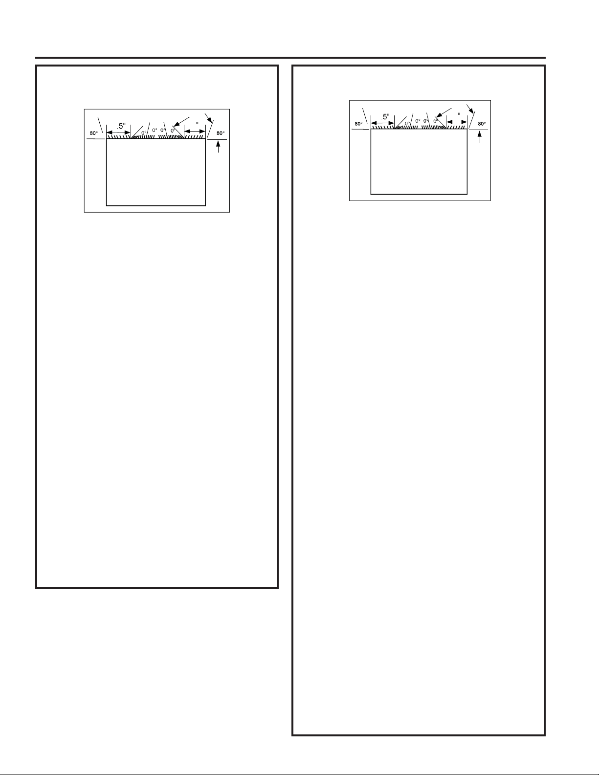
49-5000712 Rev. 1 15
Instrucciones de Instalación
INSTRUCCIONES DE INSTALACIÓN
White-Westinghouse/Frigidaire/Carrier
Serie 52F (Prof. de 16” + 17-1/2”)
4
4
3
8
3
8
1. Retire la rejilla trasera existente como se muestra en la
página 9 de este manual y reemplace la misma por el
panel trasero con celosía provisto.
NOTA: Es posible que necesite perforar agujeros sobre
la brida de la carcasa existente para que coincidan con la
nueva rejilla trasera.
$GKLHUDMXQWDODUJDGH´[´[´HQHOFHQWUR
de la parte superior de la carcasa. Retire el papel de
soporte y presione el mismo hasta su posición.
$GKLHUDMXQWDVGH´[´[´HQORVFRVWDGRV
izquierdo y derecho de la carcasa.
$GKLHUDMXQWDVODUJDVGH´[´[´YHUWLFDOPHQWH
a 4.5” desde el lado izquierdo de la carcasa y a 4”
desde el lado derecho de la carcasa.
5. Centre la unidad y de forma suave deslice la misma en
la carcasa.
6. Antes de deslizar la misma completamente hacia atrás,
retire el segundo tornillo del frente del lado izquierdo de
la unidad.
7. Retire la arandela de plástico del tornillo.
$WRUQLOOH\DGKLHUDHORWURH[WUHPRGHOFDEOHDWLHUUDD
la unidad. Asegúrese de que la arandela dentada se
encuentre contra el gabinete.
'HVOLFHODXQLGDGFRPSOHWDPHQWHVREUHODSDUWHWUDVHUD
a fin de contar con un buen sellado, asegurándose de
que el cable a tierra no quede enredado.
10. Si tiene dificultades con el montaje de la rejilla sobre
la carcasa, siga las instrucciones para un montaje
directo en la página 16.
11. Selle y enmarque la unidad como se describe en la
página 17.
White-Westinghouse o Frigidaire
(Profundidad de 22”)
1. Retire la rejilla trasera existente como se muestra en la
página 9 de este manual y reemplace la misma por el
panel trasero con celosía provisto.
NOTA: Es posible que necesite perforar agujeros sobre
la brida de la carcasa existente para que coincidan con la
nueva rejilla trasera.
Debido al incremento de profundidad en la unidad,
primero intente realizar el montaje en seco utilizando el
método descripto a continuación:
&RORTXHMXQWDVGH´[´[´FRQWUDFDGDODGR
'HIRUPDVXDYHGHVOLFHODXQLGDGKDFLDDGHQWUR\FRQWUROH
que la cantidad que se extiende desde la carcasa sea suficiente
una vez que la estructura de terminación sea adherida.
4. Si la posición es correcta, retire la unidad y proceda al
VLJXLHQWHSDVR(QFDVRFRQWUDULRYD\DDO3DVR
$GKLHUDMXQWDGH´[´[´HQORVFRVWDGRV
izquierdo y derecho de la carcasa.
&RUWHMXQWDGH´[´[´HQXQDORQJLWXGGH´
y adhiera la misma verticalmente a la rejilla trasera a
4.5” desde el lado izquierdo de la carcasa y a 4” desde
el lado derecho de la carcasa.
$GKLHUDMXQWDODUJDGH´[´[´HQHOFHQWURGH
la parte superior de la carcasa. Retire el papel de soporte
y presione el mismo hasta su posición. Proceda al paso 14.
Si la unidad requiere una extensión adicional en la sala,
consulte los siguientes pasos.
$GKLHUDODMXQWDODUJDGH´[´[´VREUHODSDUWH
vertical sólida de la rejilla trasera.
$GKLHUDEORTXHVGHJRPDHVSXPDGH´[´[
´FRQODUDQXUDVXSHUSXHVWDFRQODMXQWDTXHHVWi
arriba.
10. Instale el divisor en las ranuras de los bloques de
gomaespuma. Es posible que necesite recortar la
longitud hasta la medida.
5HSLWDORVSDVRVDSDUDODRWUDSDUWHYHUWLFDO
exhibida de la rejilla.
$GKLHUDMXQWDVGH´[´[´DORVFRVWDGRVGH
la carcasa nuevamente asegurándose de que todas las
juntas estén nivelados.
&RUWHODMXQWDGH´[ò[SDUDTXHFDOFHFRQOD
SDUWHVXSHULRUGHODFDUFDVD/DVSLH]DVVHGHEHUiQ
ajustar de forma nivelada al extremo del divisor.
14. Centre la unidad y de forma suave deslice la misma en
la carcasa.
15. Antes de deslizar la misma completamente hacia atrás,
retire el primer tornillo del frente sobre el lado izquierdo
de la unidad.
4
4
3
8
3
8
9LVWD6XSHULRU
Celosías Traseras
9LVWD6XSHULRU
Celosías Traseras
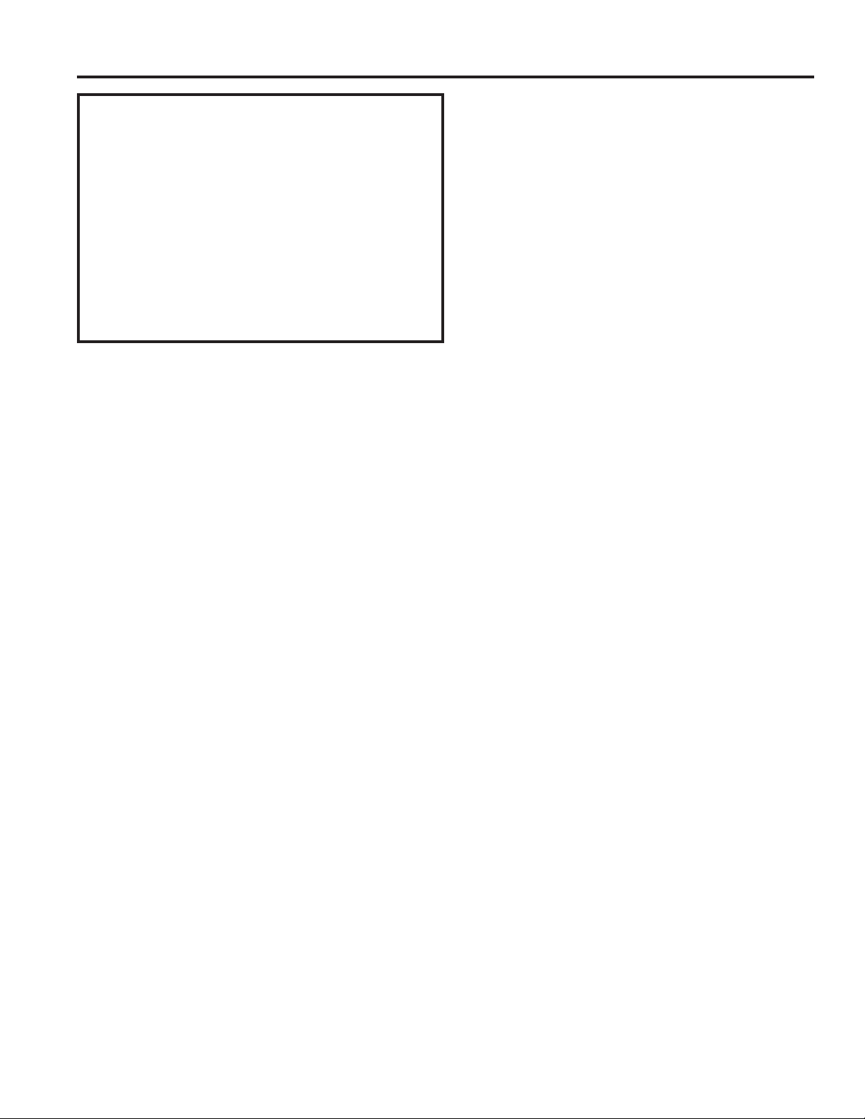
16 49-5000712 Rev. 1
INSTRUCCIONES DE INSTALACIÓN
Instrucciones de Instalación
White-Westinghouse o Frigidaire
(Profundidad de 22”)
16. Retire la arandela de plástico del tornillo.
17. Atornille y adhiera el otro extremo del cable a tierra a
la unidad. Asegúrese de que la arandela dentada se
encuentre contra el gabinete.
'HVOLFHODXQLGDGFRPSOHWDPHQWHVREUHODSDUWHWUDVHUDDILQ
de contar con un buen sellado, asegurándose de que el cable
a tierra no quede enredado.
19. Si tiene dificultades con el montaje de la rejilla sobre la
carcasa, siga las instrucciones para un montaje directo
en la página 16.
20. Selle y enmarque la unidad como se describe en la
página 17.
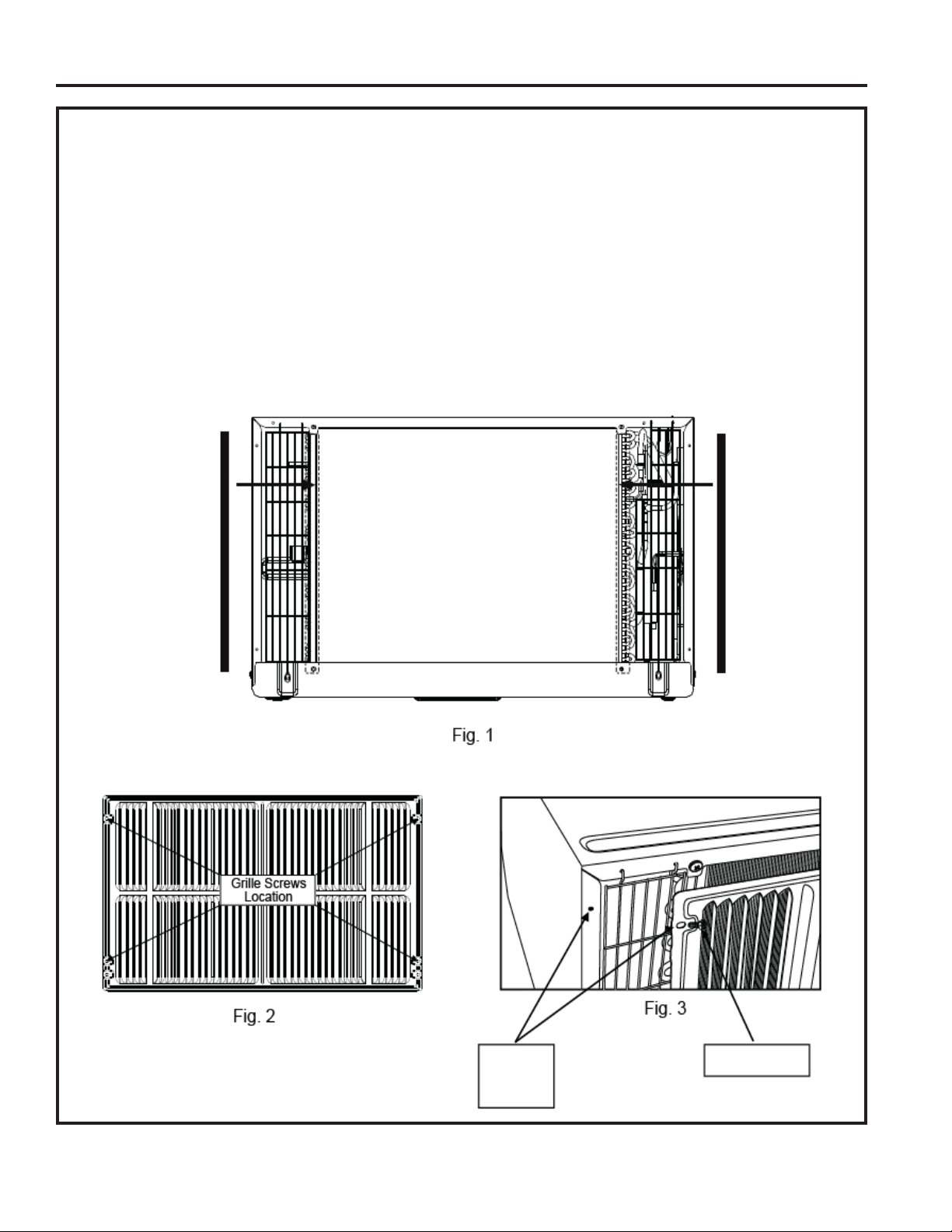
49-5000712 Rev. 1 17
INSTRUCCIONES DE INSTALACIÓN
Instrucciones de Instalación
Montaje Directo de la Unidad:
/DVLQVWUXFFLRQHVSUHYLDVVRQODIRUPDSUHIHULGDSDUDPRQWDUODQXHYDUHMLOODWUDVHUD(OUHQGLPLHQWRGHODXQLGDGHV
ligeramente mejor y la posibilidad de necesitar refuerzos se ve reducida. Como último recurso, se podrá considerar el montaje
directo de la rejilla a la unidad.
NOTA: /DUHMLOODVHGHEHUiLQVWDODUDQWHVGHLQVHUWDUODXQLGDGHQODFDUFDVD
$GKLHUDODVSLH]DVVHOODGDV´[´[´FRPRVHPXHVWUDHQODLOXVWUDFLyQ
2. Posicione la rejilla sobre la parte trasera de la unidad, asegurándose de que:
a. El conjunto doble de agujeros de tornillos se encuentre en la parte inferior.
E/RVDOHURQHVGHODUHMLOODDSXQWHQKDFLDDIXHUDGHODXQLGDG
3. Alinee la parte superior de la rejilla con la parte superior de la unidad. El excedente a cada lado deberá ser equivalente.
6LODXQLGDGQRIXHSHUIRUDGDSUHYLDPHQWHDOJXQRVPRGHORVGHIRUPDFXLGDGRVDSHUIRUHDJXMHURVGH´DWUDYpVGHODUHMLOOD
\VREUHODEULGDODWHUDOGHODXQLGDGDSUR[LPDGDPHQWHDHQWUHò´\´GHVGHODSDUWHVXSHULRUHLQIHULRUFRPRVHPXHVWUD
,QVWDOHWRUQLOORVDXWRUURVFDQWHVQSDUDILMDUODUHMLOODVREUHODXQLGDG
6. Inserte la unidad en la carcasa.
Junta Junta
Agujero de
SDUD
Rejilla y
Brida
7RUQLOORQ
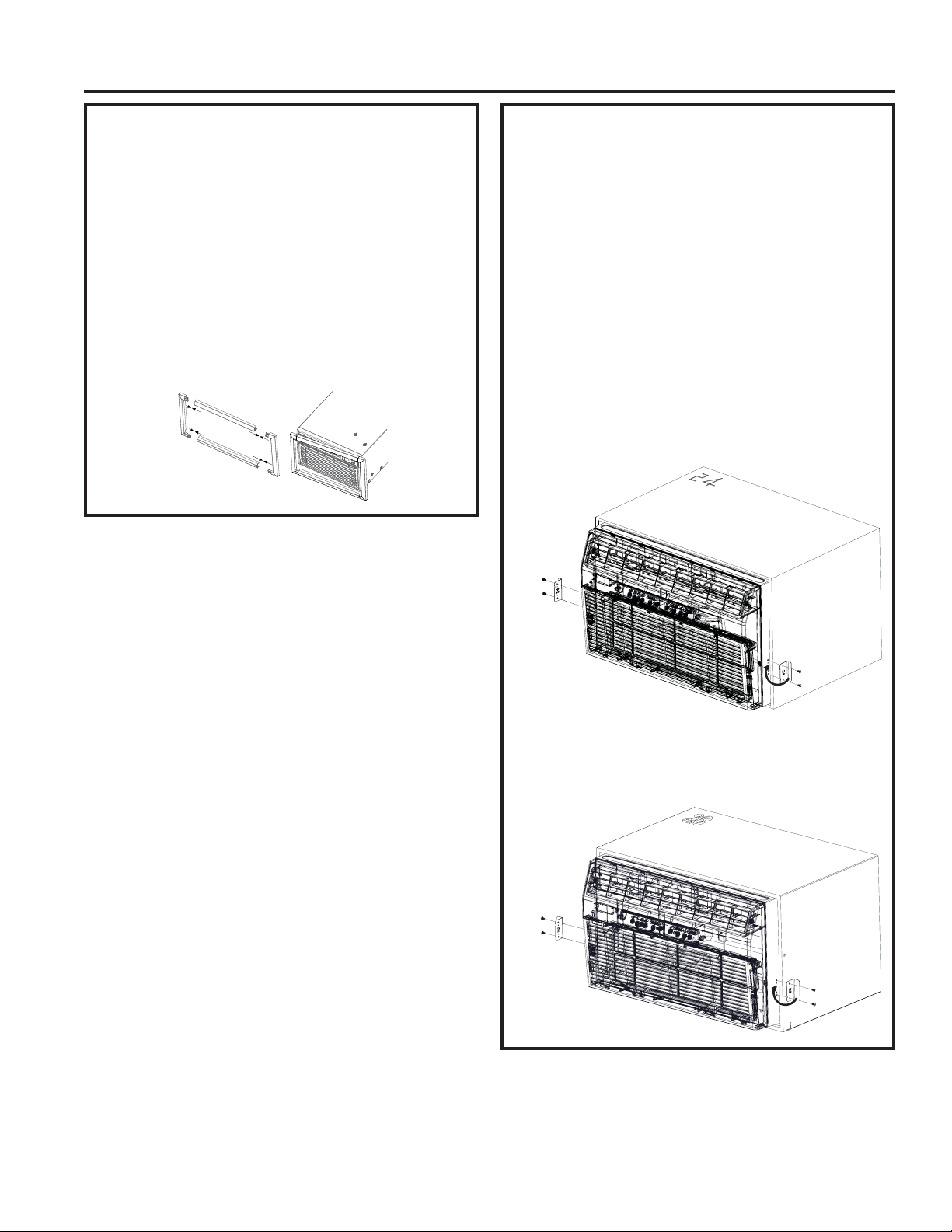
49-5000712 Rev. 1
Instrucciones de Instalación
INSTRUCCIONES DE INSTALACIÓN
Instrucciones de Instalación del Kit de
Terminaciones
Ŷ,QVWDOHODMXQWDGHUHOOHQRODUJDGH´[´[´HQWUHOD
carcasa de pared y la unidad. Se recomienda el uso de un
destornillador de punta plana o una espátula
.
Ŷ(QVDPEOHODHVWUXFWXUDFRQWHUPLQDFLyQLQVHUWDQGR
las piezas superior e inferior en las piezas laterales y
calzando las mismas en sus posiciones
.
Ŷ(PSXMHHOFDEOHDWUDYpVGHODHVWUXFWXUDFRQWHUPLQDFLyQ
y deslice el marco sobre la unidad hasta que quede
nivelada con la pared o la carcasa de pared
.
Assemble Trim
Instalación de los Soportes de
Seguridad
(Es importante instalar estos soportes
para evitar que el chasis sea empujado
dentro de la sala desde la parte exterior).
Ŷ0LGDHODQFKRGHODFDUFDVDGHSDUHGLQVWDODGD\HOLMDHO
VRSRUWHGHVHJXULGDGDGHFXDGR´R´GLVHxDGRSDUD
esa carcasa.
Ŷ/RVVRSRUWHVGHEHUiQVHULQVWDODGRVGHPRGRTXHODV
bridas sean adheridas detrás de las bridas interiores de la
FDUFDVDGHSDUHG8WLOL]DQGRORVWRUQLOORVSURYLVWRVDGKLHUD
los soportes a los costados del chasis
.
Para las carcasas de 24”, empuje la unidad levemente
hacia afuera, enganche la brida corta del soporte de
24” detrás del extremo interior de la carcasa y asegure
la unidad con los dos tornillos provistos. Repita esto
del otro lado. Empuje la unidad totalmente hacia atrás
dentro de la caja
Para las carcasas de 26”, enganche la brida corta del
soporte de 26” detrás del extremo interior de la carcasa
y asegure la misma a la unidad con los dos tornillos
provistos. Repita esto del otro lado.
Enganche el
extremo de
la carcasa
interior y
asegure la
misma a la
unidad
Enganche el
extremo de
la carcasa
interior y
asegure la
misma a la
unidad
Enganche el
extremo de
la carcasa
interior y
asegure la
misma a la
unidad
Enganche el
extremo de
la carcasa
interior y
asegure la
misma a la
unidad

49-5000712 Rev. 1 19
Consejos para Solucionar Problemas…Antes de solicitar servicio
CONSEJOS PARA SOLUCIONAR PROBLEMAS
Problema Solución
El acondicionador de aire
no se inicia
El cable de pared está desconectado. Presione el cable de manera firme en el
tomacorriente de pared.
Fusibles hogareños quemados o disyuntores desactivados. Reemplace el fusible por
uno con retraso de tiempo o reinicie el disyuntor.
Enchufe el dispositivo actualmente activado. Presione el botón RESET (Reiniciar).
La corriente está en OFF (Apagado). Presione ON (Encendido).
El aire desde la
unidad no se siente lo
suficientemente frío
La temperatura de la sala se encuentra por debajo de los 62°F (17°C). Podría no haber
refrigeración hasta que la temperatura de la sala alcance los 62°F (17°C).
El sensor de temperatura detrás del filtro de aire podría estar tocando la bobina de frío.
Evite el contacto con la bobina de frío.
Configure el mismo en una temperatura más baja.
El compresor se detuvo al cambiar de modo. Espere 3 minutos luego de configurar el
modo COOL (Frío).
El acondicionador de aire
enfría, pero la sala está
demasiado caliente. Se
forma hielo en la bobina
de refrigeración detrás del
frente decorativo.
La temperatura exterior se encuentra por debajo de los 64°F (18°C). Para descongelar la
bobina, configure el modo FAN ONLY (Sólo Ventilador).
Es posible que el filtro de aire esté sucio. Limpie el filtro. Consulte la sección de
Cuidado y Limpieza. Para descongelar, configure el modo FAN ONLY (Sólo Ventilador).
Termostato configurado en frío para la refrigeración nocturna. Para descongelar la
bobina, configure el modo FAN ONLY (Sólo Ventilador). Luego, ajuste la temperatura en
una configuración más alta.
Filtro de aire sucio, o el aire se encuentra restringido. Limpie el filtro de aire. Consulte la
sección de Cuidado y Limpieza.
La temperatura está configurada demasiado alta. Ajuste la temperatura en una
configuración inferior.
Las celosías de direccionamiento de aire fueron posicionadas de forma incorrecta.
Posicione las celosías para una mejor distribución de aire.
El frente de la unidad está bloqueado con cortinas, persianas, muebles, etc., los cuales
restringen la distribución del aire. Bloqueo claro en el frente de la unidad.
Es posible que haya puertas, ventanas, rejillas, etc. abiertas. Cierre las puertas,
ventanas, rejillas.
La unidad se encendió recientemente en una sala caliente. Espere un tiempo adicional
hasta que se elimine el “calor acumulado” en paredes, cielorrasos, piso y muebles.
El acondicionador de aire
se enciende y apaga de
forma rápida
Filtro de aire sucio; el aire se encuentra restringido. Limpie el filtro de aire.
La temperatura exterior es extremadamente caliente. Ajuste la velocidad del ventilador
en una configuración más alta, a fin de refrigerar la bobina de refrigeración exterior.
Ruido cuando la unidad se
está enfriando
Sonido del movimiento de aire. Esto es normal. Si es demasiado alto, ajuste la función
FAN (Ventilador) en una configuración más baja.
Instalación inadecuada. Consulte las instrucciones de instalación o consulte al instalador.
Gotea agua ADENTRO
cuando la unidad se está
enfriando
Instalación inadecuada. Incline el acondicionador de aire levemente hacia la parte
exterior, a fin de permitir el drenaje del agua. Consulte las instrucciones de instalación o
consulte al instalador.
Gotea agua AFUERA
cuando la unidad se está
enfriando
La unidad elimina grandes cantidades de humedad desde la sala húmeda. Esto es
normal en días extremadamente húmedos.
La sala está demasiado
fría
Configure la temperatura en el nivel bajo. Incremente la temperatura configurada.
Código de error “AS” en
la pantalla
Error del sensor de temperatura de la sala. Desenchufe la unidad y vuelva a enchufarla.
Si el error se repite, llame al servicio técnico. NOTA: En el modo Fan Only (Sólo
Ventilador), la pantalla mostrará “LO” (Bajo) o “HI” (Alto).
Código de error “HS” en
la pantalla
Error en el sensor de calefacción eléctrica. Desenchufe la unidad y vuelva a enchufarla.
Si el error se repite, llame al servicio técnico.
Código de Error “
•
” en la
pantalla
Error del sensor de temperatura del evaporador. Desenchufe la unidad y vuelva a
enchufarla. Si el error se repite, llame al servicio técnico.

20 49-5000712 Rev. 1
Notas
49-5000712 Rev. 1 21
GARANTÍA LIMITADA
Garantía Limitada del Acondicionador de Aire GE Appliances
Ŷ9LDMHVGHVHUYLFLRDVXFDVDSDUDPRVWUDUOHFyPR
funciona el equipo.
Ŷ,QVWDODFLyQRHQWUHJDLQDSURSLDGDRPDQWHQLPLHQWR
impropio. Si usted tiene un problema durante la
instalación, o si su acondicionador de aire no tiene
la capacidad de enfriamiento que usted necesita,
póngase en contacto con nuestro distribuidor o
instalador. Usted es responsable de proporcionar
las facilidades de conexión eléctrica necesarias.
Ŷ)DOORGHOSURGXFWRUHVXOWDQWHGHPRGLILFDFLRQHVDO
producto o debido a uso irrazonable incluyendo
no proporcionar mantenimiento razonable y
necesario.
Ŷ(QORFDOHVFRPHUFLDOHVODPDQRGHREUDQHFHVDULD
para retirar la unidad hacia un lugar para revisión
por parte de un técnico individual.
Ŷ5HHPSOD]RGHIXVLEOHVGHODFDVDRUHDMXVWHGHO
sistema de circuitos.
Ŷ)DOORVGHELGRDODFRUURVLyQHQPRGHORVTXHQR
están protegidos contra la corrosión.
Ŷ'DxRDOSURGXFWRFDXVDGRSRUYROWDMHLQDSURSLDGR
hacia el equipo, accidentes, incendios,
inundaciones o actos de la naturaleza de fuerza
mayor.
Ŷ'DxRVLQFLGHQWDOHVRFRQVHFXHQFLDOHVFDXVDGRV
por defectos posibles con este acondicionador de
aire.
Ŷ'DxRVGHVSXpVGHODHQWUHJD
Qué No Cubrirá GE Appliances:
Esta garantía limitada se extiende al comprador original y cualquier comprador posterior de productos comprados
SDUDXVRUHVLGHQFLDOGHQWURGH(VWDGRV8QLGRV6LHOSURGXFWRHVWiVLWXDGRHQXQiUHDTXHQRGLVSRQHGHVHUYLFLR
por parte de un proveedor de servicio autorizado de GE Appliances, podría tener que hacerse cargo de los costes
de envío o bien podría solicitársele que lleve el producto a una centro de servicio de GE appliances autorizado para
realizar la reparación. En Alaska, la garantía limitada excluye el costo de envío o las visitas de servicio a su casa.
Algunos estados no permiten la exclusión o las limitaciones de daños incidentales o consecuenciales. Esta garantía
limitada da derechos legales específicos, y usted podría tener otros derechos que variarán de estado a estado.
Para saber cuáles son sus derechos legales, consulte a la oficina de asuntos del consumidor local o la oficina del
Attorney General en su localidad.
Garante: GE Appliances, a Haier company
Louisville, KY 40225
Todo el servicio de garantía deberá ser provisto por nuestros Centros de Servicio de Fabricación, o por un técnico
DXWRUL]DGRGHO6HUYLFLRDO&OLHQWH&XVWRPHU&DUH
®
3DUDSURJUDPDUXQDYLVLWDGHOVHUYLFLRWpFQLFRDWUDYpVGH,QWHUQHW
visítenos en GEAppliances.com/serviceROOiPHQRVDO*(&$5(6&XDQGROODPHSDUDVROLFLWDUHO
servicio, tenga los números de serie y modelo disponibles.
EXCLUSIÓN DE GARANTÍAS IMPLÍCITAS—Su único y exclusivo derecho es la reparación del producto,
tal y como se indica en esta Garantía limitada. Cualquier garantía implícita, incluyendo las garantías
implícitas de comerciabilidad o adecuación para un fin determinado, están limitadas a dos años o el
período de tiempo más breve permitido por la ley.
Por el período de: GE Appliances Reemplazará:
Dos Años
A partir de la fecha de
la compra original
Cualquier parte del acondicionador de aire que falle debido a defectos en los materiales
RHQODIDEULFDFLyQ'XUDQWHHVWDgarantía limitada de dos años, GE Appliances también
proporcionará, sin costo alguno, toda la mano de obra y el servicio relacionado—para
reemplazar partes defectuosas.
Grape aquí su recibo. Se requiere facilitar prueba de la fecha
de compra original para obtener un servicio bajo la garantía.

22 49-5000712 Rev. 1
Impreso en China
Soporte para el Consumidor
SOPORTE PARA EL CONSUMIDOR
Sitio Web de GE Appliances
¢'HVHDUHDOL]DUXQDFRQVXOWDRQHFHVLWDD\XGDFRQVXHOHFWURGRPpVWLFR"£,QWHQWHDWUDYpVGHO6LWLR:HEGH*($SSOLDQFHVODV
KRUDVGHOGtDFXDOTXLHUGtDGHODxR8VWHGWDPELpQSXHGHFRPSUDUPiVHOHFWURGRPpVWLFRVPDUDYLOORVRVGH*($SSOLDQFHV\
aprovechar todos nuestros servicios de soporte a través de Internet, diseñados para su conveniencia.
(Q((88GEAppliances.com
Registre su Electrodoméstico
£5HJLVWUHVXHOHFWURGRPpVWLFRQXHYRDWUDYpVGH,QWHUQHWVHJ~QVXFRQYHQLHQFLD8QUHJLVWURSXQWXDOGHVXSURGXFWRSHUPLWLUi
una mejor comunicación y un servicio más puntual de acuerdo con los términos de su garantía, en caso de surgir la necesidad.
También puede enviar una carta en la tarjeta de inscripción preimpresa que se incluye con el material embalado.
(Q((88GEAppliances.com/register
Servicio Programado
El servicio de reparación de expertos de GE Appliances está a sólo un paso de su puerta. Conéctese a través de Internet y programe
VXVHUYLFLRDVXFRQYHQLHQFLDFXDOTXLHUGtDGHODxR(Q((88GEAppliances.com/serviceRFRPXQtTXHVHDO
durante el horario de atención comercial.
Garantías Extendidas
Adquiera una garantía extendida de GE Appliances y conozca los descuentos especiales que están disponibles mientras su
JDUDQWtDD~QHVWiYLJHQWH/DSXHGHDGTXLULUHQFXDOTXLHUPRPHQWRDWUDYpVGH,QWHUQHW/RVVHUYLFLRVGH*($SSOLDQFHVD~Q
estarán allí cuando su garantía caduque.
(Q((88GEAppliances.com/extended-warrantyRFRPXQtTXHVHDOGXUDQWHHOKRUDULRGHDWHQFLyQFRPHUFLDO
Piezas y Accesorios
Aquellos individuos calificados para realizar el servicio técnico de sus propios electrodomésticos podrán solicitar el envío de
SLH]DVRDFFHVRULRVGLUHFWDPHQWHDVXVKRJDUHVVHDFHSWDQODVWDUMHWDV9,6$0DVWHU&DUG\'LVFRYHU2UGHQHKR\DWUDYpVGH
,QWHUQHWGXUDQWHODVKRUDVWRGRVORVGtDV(Q((88GEApplianceparts.comRGHIRUPDWHOHIyQLFDDOGXUDQWH
el horario de atención comercial.
Las instrucciones que figuran en este manual cubren los procedimientos que serán realizados por cualquier usuario.
Otros servicios técnicos generalmente deben ser derivados a personal calificado del servicio. Se deberá tener cuidado,
ya que una reparación indebida podrá hacer que el funcionamiento no sea seguro.
Contáctenos
Si no se encuentra satisfecho con el servicio que recibió de GE Appliances, comuníquese con nosotros a través de nuestro sitio
Web con todos los detalles, incluyendo su número telefónico, o escriba a:
(Q((88*HQHUDO0DQDJHU&XVWRPHU5HODWLRQV_*($SSOLDQFHV$SSOLDQFH3DUN_/RXLVYLOOH.<
GEAppliances.com/contact