Loading ...
Wiring
Wiring Diagrams
Technician Setup Technician Setup
Caution:
Electrical Hazard
All components of the
control system and the
thermostat installation must
conform to Class II circuits
per the NEC Code.
Warning:
Do not overtighten terminal
block screws, as this can
damage the terminal block.
A damaged terminal block
can keep the thermostat
from tting on the subbase
correctly or cause system
operation issues.
Installation Tip
Max Torque = 6in-lbs.
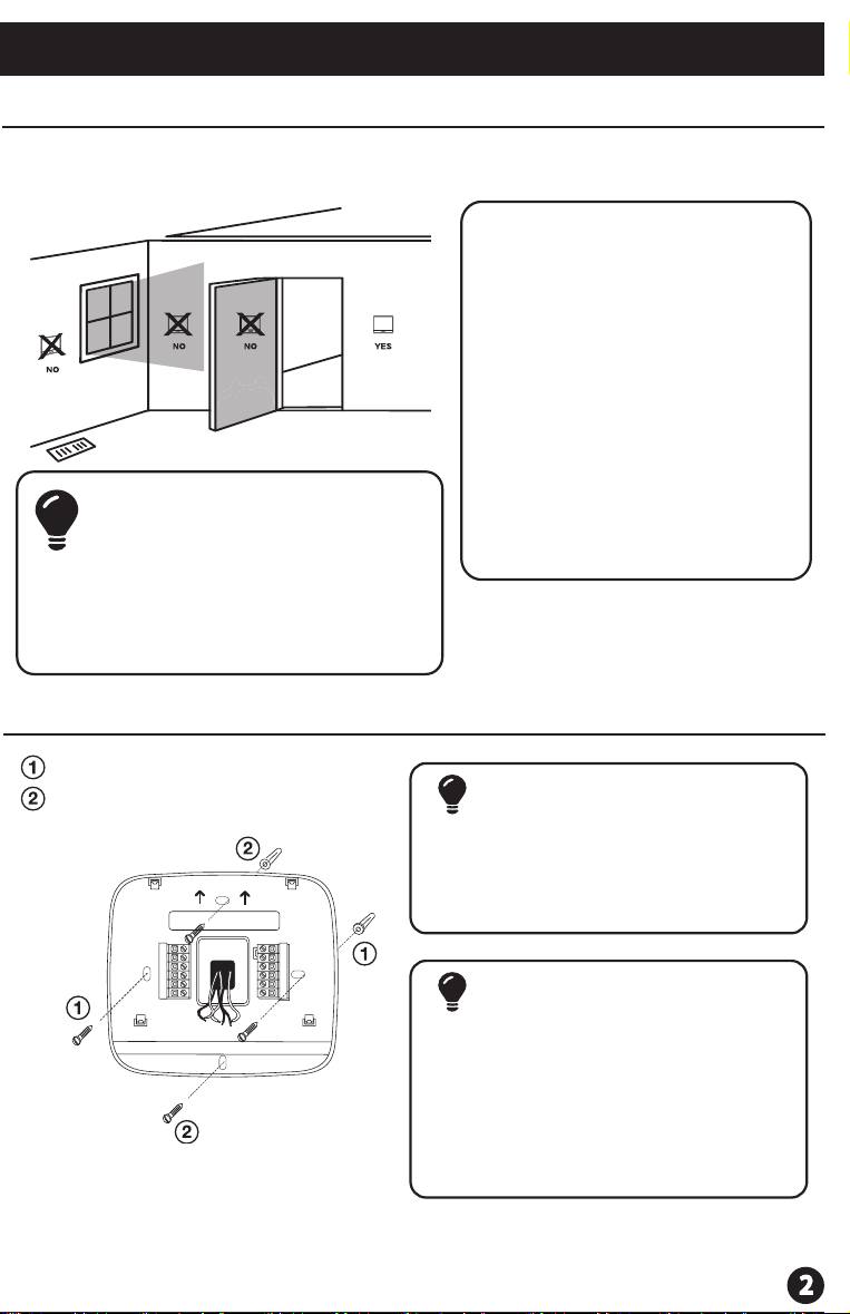
Wiring
If you are replacing a thermostat,
make note of the terminal
connections on the thermostat
that is being replaced. In some
cases the wiring connections will
not be color coded. For example,
the green wire may not be
connected to the G terminal.
Loosen the terminal block
screws. Insert wires then
retighten terminal block screws.
Place nonammable insulation
into wall opening to prevent
drafts.
1.
2.
3.
Terminal Designations
R
Failure to disconnect the power
before beginning to install this
product can cause electrical
shock or equipment damage.
C
B
O
G
W/E
W2
Y
Heat Pump System
1 HEAT 1 COOL / 2 HEAT 1 COOL
Conventional System
1 HEAT 1 COOL / 2 HEAT 1 COOL
Transformer Power
Transformer Common
Changeover Valve
Energized in HEAT
Fan Relay
First Stage of Emergency HEAT
Changeover Valve
Energized in COOL
Second Stage of HEAT/
EMERGENCY HEAT
First Stage of HEAT and COOL
Transformer Power
Transformer Common
Fan Relay
First Stage of HEAT
Second Stage of HEAT
First Stage of COOL
Energized in HEAT
Energized in COOL
Power supply
Use either O or B terminals for changeover valve.
Optional 24 VAC common connection when thermostat is used in battery power mode.
Factory-supplied jumper
R
Y
C
W/E
G
W2
O
B
COMPRESSOR
RELAY
FAN RELAY
AUXILIARY
COOL CHANGE
OVER VALVE
HEAT CHANGE
OVER VALVE
C
R
L2
L1(HOT)
2H/1C Heat Pump System - Factory Default Setting
Typical 2H/1C Heat Pump System with separate emergency heat
R
Y
C
G
W2
COMPRESSOR
RELAY
EMERGENCY
RELAY
AUXILIARY
COOL CHANGE
OVER VALVE
HEAT CHANGE
OVER VALVE
O
B
C
R
L2
L1(HOT)
FAN RELAY
Note: In many systems
with no emergency heat
relay a jumper can be
used between E and W2.
Conventional System 1H/1C, 2H/1C (Heat pump set to “OFF” in tech settings)
Note: This
thermostat is only
compatible with
ONE transformer
systems.
R
Y
C
G
W2
COMPRESSOR
RELAY
HEAT RELAY
FAN RELAY
HEAT RELAY 2
C
R
L2
L1(HOT)
1. Select OFF with the System Switch for Tech Settings. Select Heat or Cool for Swing
and Limit settings. They are set separately.
2. Hold down the + and - buttons together for 3 seconds.
3. Use the + and - to change setting for that step, and the glow in the dark light button to
move from one step to another.
The compressor short cycle delay
protects the compressor from
short cycling. This feature will
not allow the compressor to be
turned on for 5 minutes after it
was last turned o.
Selecting “ON” will not allow
the compressor to be turned
on for 5 minutes after the
last time the compressor
was switched o. Select
“OFF” to remove this delay.
0
This feature allows the installer
to change the calibration of the
room temperature display. For
example, if the thermostat reads
70 degrees and you would like it
to read 72 then select +2.
0
CA
Room
Temperature
Calibration
You can adjust the room
temperature display to
read 4˚above or below the
factory calibrated reading.
Compressor
Short Cycle
Delay
0N
Cd
Select F for Fahenheit
temperature read out or select C
for Celsius read out.
F for Fahrenheit
C for Celsius
F or C
F
F
FC
o
0.8
The swing setting often called
“cycle rate”, “dierential” or “
anticipation” is adjustable. A
smaller swing setting will cause
more frequent cycles and a larger
swing setting will cause fewer
cycles.
Cooling
Swing
The cooling swing setting is
adjustable from 0.2˚ to 2˚. For
example: A swing setting of
0.5˚will turn the cooling on at
approximately 0.5˚ above the
setpoint and turn the cooling o
at approximately 0.5˚ below the
setpoint.
Tech Settings
Heating
Swing
Tech Settings
Tech Settings
Adjustment Options Default
LCD Will Show
Adjustment Options Default
LCD Will Show
Select GAS for systems that
control the fan during a call for
heat. Select ELEC to have the
thermostat control the fan during
a call for heat.
EL - Electric for thermostat
control
GS- Gas for system control
Fan
Operation
EL
When set to ON this thermostat
will operate a heat pump system
(default). If set to OFF this
thermostat will operate a
conventional system, and the next
tech step will not appear.
ON - Congured to operate
heat pump system.
OFF - Congured to operate
conventional system
See page 5 for terminal
designations.
Heat Pump
ON
For Dual Fuel applications (Gas/
Fossil fuel Auxiliary Heat), turn
this setting ON to LOCKOUT the
Heat Pump (Y) when Auxiliary
Heat (W2) is on. If desired- This can
also be used with Electric Auxiliary.
OFF will allow Y(1st stage of
Heat) and W2 (Aux Heat) to run
together if called for.
ON Will de-energize Y terminal
45 seconds after a call for
Auxiliary Heat (W2).
Dual Fuel
Auxiliary for
Heat Pump
Will only appear if
Heat Pump setting is
turned ON
OFF
This feature allows the thermostat
to keep multiple stages of heat
energized until setpoint is
satised.
Use the or key to
turn ON or OFF.
Satisfy
Setpoint
OFF
This feature allows a delay to occur
when a second stage is needed.
This allows the previous stage
extra time to satisfy setpoint.
Use the or key to
select OFF, 5, 10, 15, 30, 45,
60, or 90 minutes.
Staging
Delay
OFF
0.8
The heating swing setting is
adjustable from 0.2˚ to 2˚. For
example: A swing setting of
0.5˚will turn the heating on at
approximately 0.5˚ below the
setpoint and turn the heating o
at approximately 0.5˚ above the
setpoint.
The swing setting often called
“cycle rate”, “dierential” or “
anticipation” is adjustable. A
smaller swing setting will cause
more frequent cycles and a larger
swing setting will cause fewer
cycles.
Cooling
Setpoint
Limit
44
To exit setup slide the system switch to dierent position or wait approximately 20 seconds.
Heating
Setpoint
Limit
90
This feature allows you to set a
minimum cool setpoint value.
The setpoint temperature can’t be
lowered below this value.
Use the and key to select
the minimum cool setpoint.
This feature allows you to set a
maximum heat setpoint value.
The setpoint temperature can’t
be raised above this value.
Use the and key to select
the maximum heat setpoint.
This feature controls the number
of stages in Emergency Heat
mode. It only appears if the
Technician Setup Step for HEAT
PUMP is ON.
Use the or key to
select 1-stage or 2-stage
operation.
Emergency
Heat Stages
1
Swing and Limit Settings
Adjustment Options
Default
LCD Will Show
W/E
W/E