®
LOTOS TECHNOLOGY
www.uwelding.com
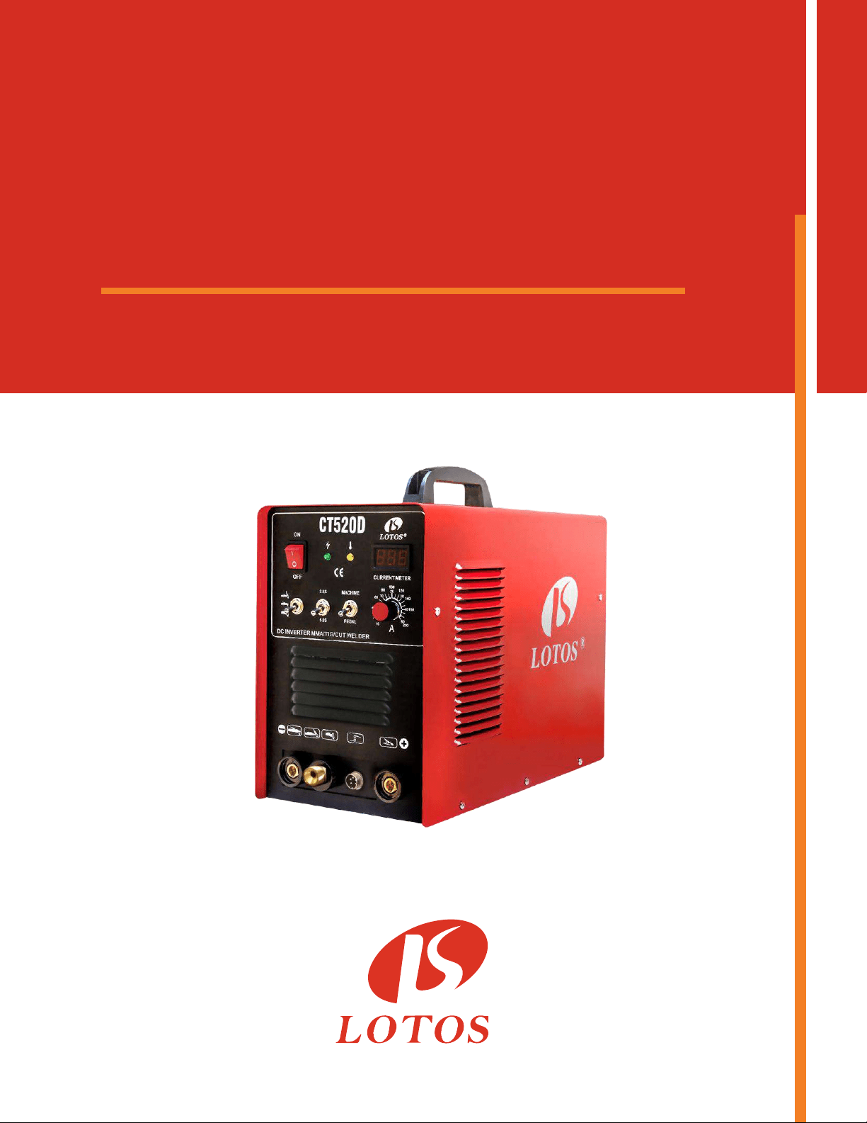
Plasma Cutter TIG Stick Welder CT520D

®
Lotos Technology CT520D
Quick Setup
Power plug wiring:
For either 110 or 220VAC, the GREEN wire is the ground wire. The WHITE and BLACK wires are hot
wires.
For Plasma Cung:
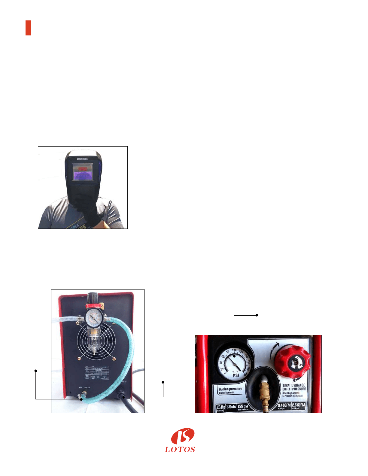
1. Wear a Lotos auto darkening plasma cung helmet
(Figure 1.1, not included in the box. To purchase, please
go to our website.) to protect your eyes from harmful
plasma cung arc radiaon and safety gloves to protect
your hands during welding.
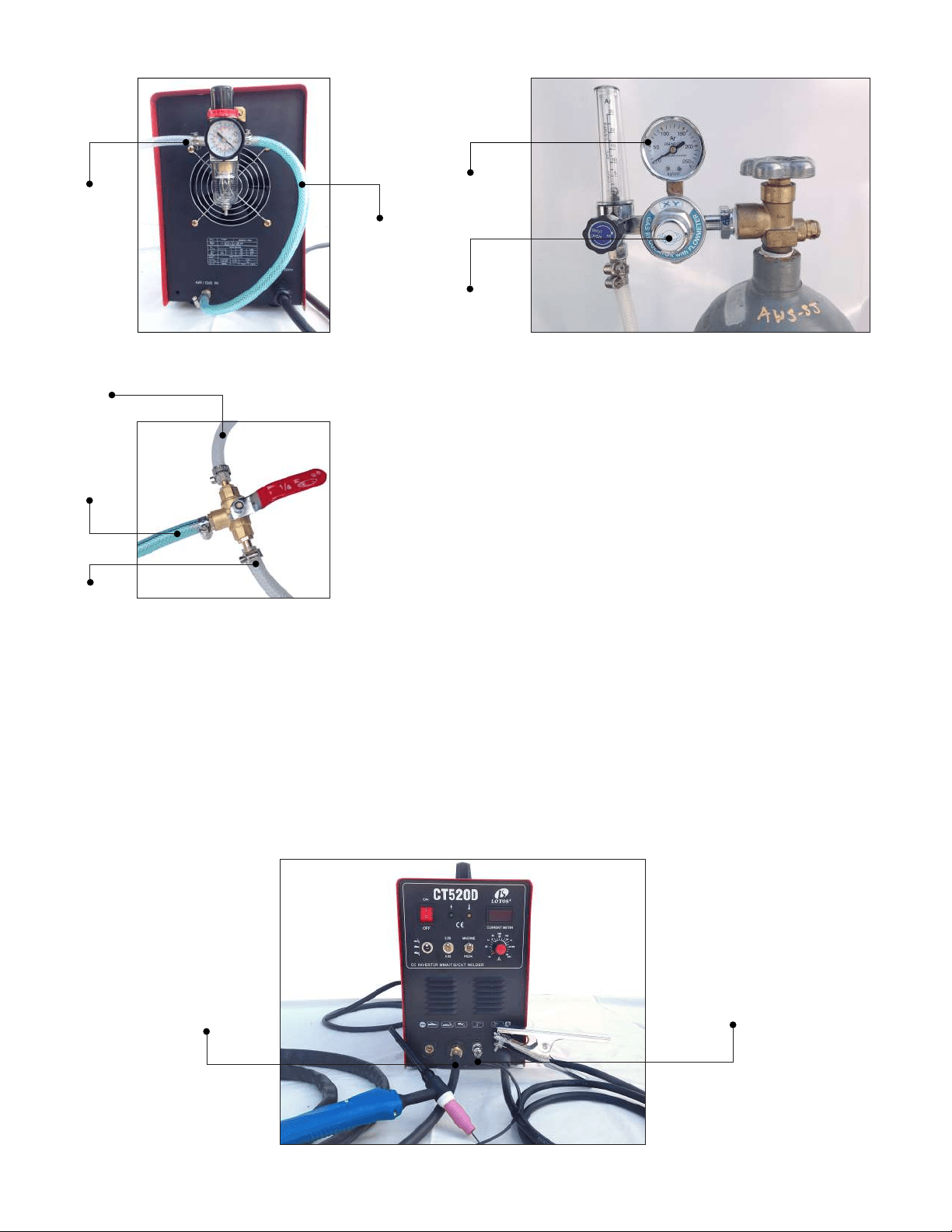
2. Connect the machine gas inlet (on the back of the machine, Figure 1.2) with an air compressor
(Figure 1.3) and set the air pressure to 65-70 PSI. (The Air Regulator is oponal if your air
compressor has the capability to control output air pressure.)
Instructions
Figure 1.1
Figure 1.2 Figure 1.3
65 - 70 PSI
Power
Cord
Gas
Inlet
1
®
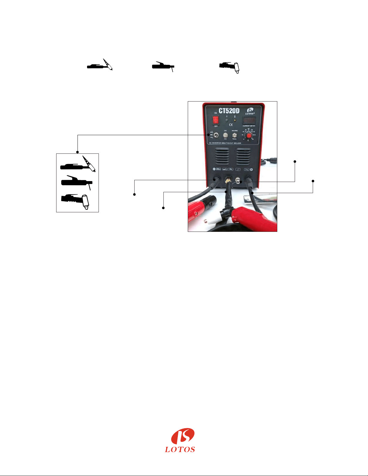
3. Connect your plasma cung torch and ground cable to the front panel of the machine. Make
sure the ground cable is connected on the right hand side where the “+” sign is located.
(Figure 1.4)
- Set TIG Weld /Sck Weld /Plasma Cut switch to Plasma Cut mode.
- Set “2.5S/5S” to “2.5S” Mode.
- Set “Machine/PEDAL” to “Machine” Mode.
- Adjust Current Dial between 10 and 50 amps.
4. Aach the ground clamp to the metal you want to cut. Grind the metal to make sure the clamp
is securely aached to the work piece. Press the trigger of the torch and make sure the air is
owing. Finally, move the torch head to the work piece and start cung.
5. Change your consumables (p, electrode, ring, and cup) if they are worn out. The consumables’
type is LCON. If you want to cut the perfect circle or perfect straight line, order a Lotos
LCK roller guider compass kits from our website www.uwelding.com.
1. Wear our auto darkening helmet and gloves to protect your eyes and hands from any harmful
welding arc. (Please see step 1 in Plasma Cung.)
2. Connect the machine gas inlet (on the back of the machine, Figure 1.5) to the argon regulator
and adjust the knob to set gas pressure between 15 and 20 min/L (an argon regulator is
necessary, Figure 1.6.)
For TIG Welding:
Figure 1.4
STICK
Welding
Clamp
Plasma
Torch
Output
5-pin
Switch
Plug
Ground
Cable
2
a) If you switch from plasma cung to TIG welding quite oen,
consider buying a LOTOS 3 way valve kit to connect both the
argon tank (Figure 1.7) and the air compressor simultaneously.
- Connect your TIG torch and ground cable to the front panel of the machine.
- Make sure the ground cable is connected on the right hand side where the “+” sign is located.
- Set TIG Weld/Sck Weld/Plasma Cut switch to TIG Weld mode (refer to Figure 1.4, page 2).
- Set “2.5S/5S” to “2.5S” mode.
- Set “Machine/PEDAL” to “Machine” mode.
- Adjust current dial from 10 to 200 amps (Figure 1.8).
Figure 1.5 Figure 1.6
Figure 1.7
Figure 1.8
Output
from
Air
Compressor
Argon
Regulator
Argon
Gas
Machine
Gas
Inlet
Air
Compressor
15-20
min/L
5-pin
Switch
Plug
TIG
Torch
Output
3
®
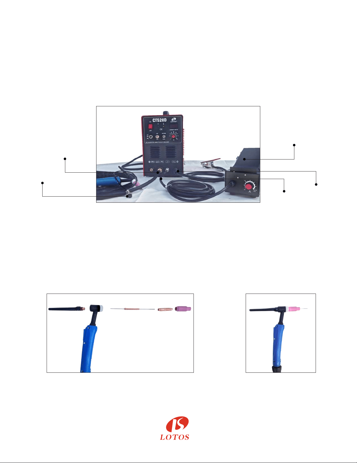
b) If you want to dynamically control the welding heat, please use a foot pedal (not included in the
box. To purchase, please go to our website). Then connect the “on/o” connector to your foot
pedal and leave the wire of the TIG torch unplugged.
- Set TIG Weld/Sck Weld/Plasma Cut switch to TIG Weld mode (refer to Figure 1.4, page 2).
- Set “2.5S/5S” to “2.5S” mode.
- Set “Machine/PEDAL” to “Pedal” mode.
- Adjust current dial between 10 and 200 Amp (Figure 1.9).
3. TIG torch head parts (Figure 1.10) and assembly (Figure 1.11)
(The tungsten is not included in the picture; please buy proper DC Lotos tungsten electrodes.)
Grind and sharpen the tungsten before rst use.
Figure 1.9
Figure 1.10 Figure 1.11
Foot
Pedal
with
Amp Adjusts
Ground
Cable
5-pin
Foot Pedal
Plug
TIG Torch
Output
Unplugged
4
®
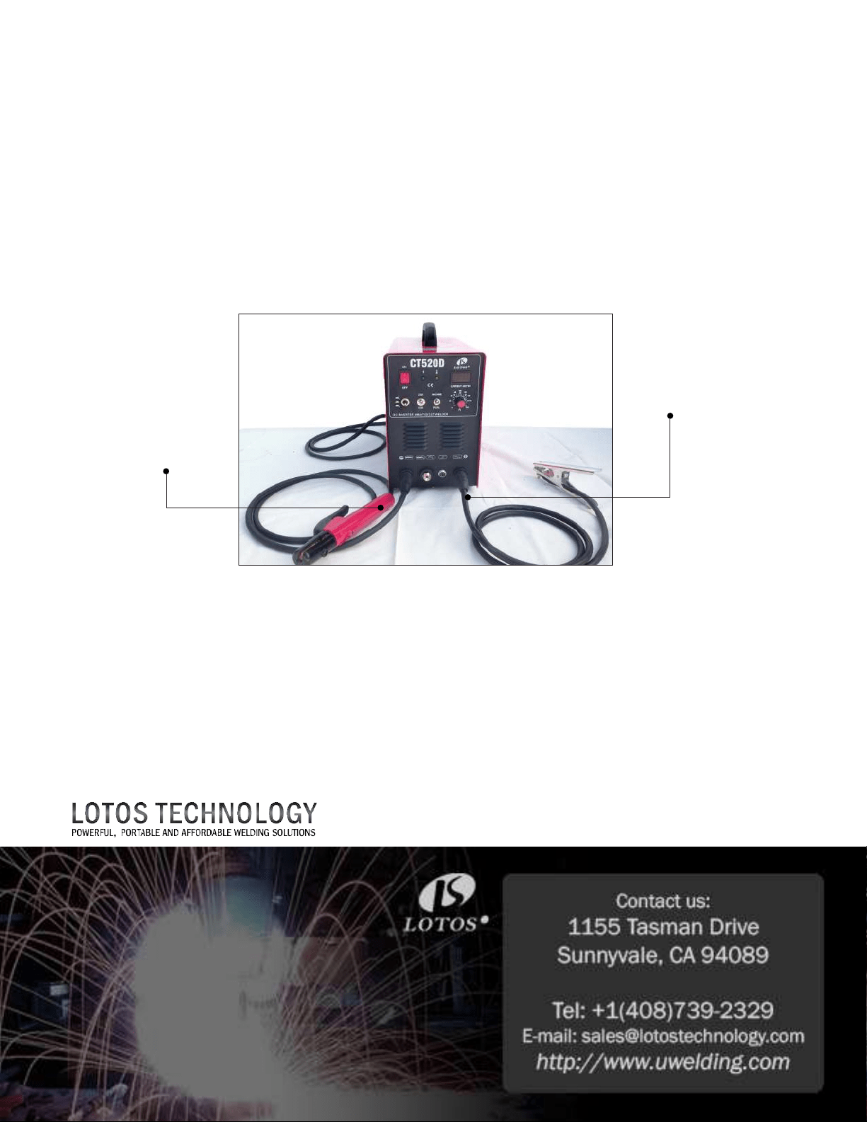
For Sck/Arc/MMA Welding:
1. Wear our auto darkening welding helmet and gloves to protect your eyes and hands from any
harmful welding arc. (Please see step 1 in Plasma Cung.)
2. You don’t need to connect the machine to any gas or air supply. It’s a plug and play.
Panel connecon instrucons:
- Set TIG Weld/Sck Weld/Plasma Cut switch to Sck Weld mode (refer to Figure 1.4, page 2).
- Set “2.5S/5S” to “2.5S” mode.
- Set “Machine/PEDAL” to “Machine” mode.
- Adjust current dial between 10 and 200 amps (Figure 1.12).
IMPORTANT: To avoid damaging the machine, please be sure to turn o the machine when you
switch from one funcon to another.
All accessories and consumables can be purchased at www.uwelding.com or Lotos’s authorized
resellers.
Thank you for your business!
Figure 1.12
Ground
Cable
Stick
Welding
Clamp

®
LOTOS CT520D
User Manual
Version: 3.0, June 2017
copyright @ Lotos Technology
www.uwelding.com is operated by Lotos Technology

For more information and more of our products,
please visit our website at
http://www.uwelding.com/
Introducon 6
Overview ................................................................................
Audience ................................................................................
Safety Precauons
7
Overview .................................................................................
Cauon Recommendaons .................................................................
Avoiding Fatal Electric Shock ................................................................
Avoiding Harmful Smoke, Gases, and Vapors ..................................................
Avoiding Harmful Arc Emissions/Rays ........................................................
Avoiding Harmful Noises ...................................................................
Fire or Explosion ..........................................................................
Burn Protecon ...........................................................................
Protecng Eyes from Flying Metal or Dirt .....................................................
Pacemakers ..............................................................................
Cylinder Handling .........................................................................
Equipment
9
General Overview .........................................................................
Main Characteriscs .......................................................................
Specicaons .............................................................................
Adjustor Diagram .........................................................................
Air Regulator Conguraon ................................................................
Connecng Cables to Machine..............................................................
Installaons ..............................................................................
Instrucon Notes
20
Working Environment .....................................................................
Safety ...................................................................................
Maintenance .............................................................................
Troubleshoong ..........................................................................
Table of Contents
7
7
7
7
7
7
8
8
8
8
8
9
9
9
12
12
13
15
16
16
18
20
20
21
21
6
6
Gas Regulator Installation ..................................................................
Argon Installaon .........................................................................
Operaon ...............................................................................
17
Tips for Cutting . . . . . . . . . . . . . . . . . . . . . . . . . . . . . . . . . . . . . . . . . . . . . . . . . . . . . . . . . . . . . . . . . . . .
. . .

®
6
Introduction
Overview
Dear Valued Customer:
Thank you for purchasing a Lotos Technology plasma cuer! Feel free to check out our other products at
www.uwelding.com.
This User Manual documents policies and procedures for proper operaon of the equipment.
IMPORTANT: Be sure to review the contents of this manual before aempng to operate the equipment.
This manual should be located where it can be easily referenced by all users of the machine.
Audience
This manual assumes that all individuals reading the manual and using the welder/cuer are able,
qualied, and/or cered to operate this type of machinery.
®
Safety Precautions - Read Before Using
Overview
Cauon Recommendaons
Arc rays from the welding process pro-
duce intense visible and invisible rays
that can burn eyes and skin. Sparks y
o from the weld.
CAUTION: Welding and arc cung
can cause bodily injury.
• Connect the machine to a UL-approved outlet
only. Do not hard wire the machine directly to
the power source.
• Wear safety goggles at all mes. This will dark-
en the arc that is generated by the machine and
protect your eyes from harmful rays.
• All machine operators should be technically
cered for welding/cung.
Avoiding Harmful Smoke, Gases, and Vapors that can injure or kill.
Avoiding Harmful Arc Emissions/Rays that can burn eyes and skin.
Avoiding Fatal Electric Shock
Protect yourself and others from injury — read and follow these precautions.
Welding produces fumes and gases.
Breathing these fumes and gases can
be hazardous to your health.
7
• Do NOT switch o the machine while machine is
in operaon for internal circuitry can be
damaged.
• Wear appropriate clothing and a welding or
cung mask to protect your eyes and skin.
• Use appropriate screen or curtain to prevent
emissions from reaching individuals near the
work area.
• Ensure that your working area contains no
ammable items; and that none are nearby.
Cauon: Welding and cung spray can ignite.
Avoiding Harmful Noises that can damage hearing.
Noise from some processes can
damage hearing.
• Wear protecve earplugs while operang
machine.
• Isolate yourself from both the
earth and the work piece.
• Make sure that your working area is
nonammable and explosive-free.
®
Burn Protecon: HOT PARTS can cause serious burns.
Protect eyes from FLYING METAL or DIRT.
PACEMAKERS AND WELDING: MAGNETIC FIELDS can aect implanted devices.
CYLINDER HANDLING: it can explode if damaged.
Welding or Cung can cause Fire or Explosion.
If you encounter any dicules during set up or operaon:
• Consult this manual.
• Contact Lotos Customer Service by vising
hp://www.uwelding.com/about-us/contact-us/.
The work piece and equipment
get hot. The hot metal, hot work
piece, and hot equipment can
cause burns.
• Welding, chipping, wire
brushing, and grinding cause
sparks and ying metal.
Electric arc welding and cung
processes produce intense electric
and magnec (electromagnec)
elds. The funcon of pacemakers
can be aected by strong electro-
magnec elds.
Shielding gas cylinders contain gas
under high pressure. If damaged,
a cylinder can explode. Be sure to
treat gas cylinders carefully.
Welding, cung, and allied pro-
cesses can cause re or explosion
if precauonary measures are not
followed.
• Use approved helmets or hand shields that
provide protecon for the face, neck, etc.
• Wear approved safety goggles or glasses with
side shields, even under your helmet.
• Wear approved safety glasses with side shields,
even under your welding helmet.
• Persons with a pacemaker should not go near
welding or cung operaons unl they have
consulted their doctors and obtained informaon
from the manufacturer of the device.
• Protect compressed gas cylinders from excessive
heat, mechanical shocks, physical damage, slag,
open ames, sparks, and arcs.
• Install cylinders in an upright posion by securing
to a staonary support or cylinder rack to prevent
falling or pping.
• Develop adequate procedures, and use proper
equipment to do the job safely.
• Keep cylinders away from any welding or other
electrical circuits.
• Wear dry, hole-free insulated gloves.
• Remove combusble materials from a sphere
with a minimum radius of 35 feet around the
work area or move the work to a locaon well
away from combusble materials.
8
®
Equipment
General Overview
Manufactured with advanced inverter technology, the CT520D mulpurpose unit includes the following
features: stable output, reliable, completely portable, high-eciency and low noise generated while
cung.
Main Characteriscs
The LOTOS CT520D series DC TIG, MMA, and plasma cuer allows you to weld stainless steel, alloy steel
and carbon steel and other nonferrous metals.
9
• Stabilizaon
• Reliability
• Portability
• Power eciency and low noise output
• High cung speed
• Smooth cuts
General
Model name CT520D
Functions
50 A Plasma Cutter
200 A TIG Welder
200 A STICK Welder
Dimension with handle
Weight 32 lbs (14.5 kg)
Input voltage 110-220 V, 1-PH, 50/60 Hz
Power supply type Inverter - IGBT
Housing protection IP21
Insulation B
Efficiency 85%
Accessories
Plasma cutting torch 50 A, 12.5 ft. (3.81m)
TIG welding torch 200 A 12.9 ft. (3.93m)
Arc/Stick clamp 200 A 6.5 ft. (1.98m)
Argon regulator 0-250 psi
Air regulator 0-150 psi
Specicaons
The CT520D multipurpose unit offers a variety of welding and cutting aspects. It is able to cut all types
of metal up to 1/2’’ with the 50A Plasma cutting function. This LOTOS multi-process welder can switch
between TIG Weld and STICK Weld quickly and easily. With a hand carrying weight of 32lbs, the unit is
portable and reliable featuring a duty cycle of 60% at max amps on all processes.
Plasma
Cutting
Rated input power requirement
220 V, 1-PH, 35 A
110 V, 1-PH, 45 A
Output current
10-50 A @220V
10-25 A @110V
Duty cycle @ 40°C (104°F)
60% @ 50 A
100% @ 40 A
Gas supply Clean, dry, oil-free air
Recommended gas inlet
flow rate / pressure
3.6 scfm @ 65 psi
80L/min
Max rated cutting thickness 1/2 inches (12.7mm)
DC
TIG
Welding
Rated input power requirement
220 V, 1-PH, 30 A
110 V, 1-PH, 40 A
Output current
10-200 A @ 220V
10-100 A @ 110V
Material can weld Steel, Stainless, Moly, Ferrous
Duty cycle @ 40°C (104°F)
60% @ 200 A
100% @ 150 A
No load voltage 62 V
Working voltage 16.9 V
Gas supply Clean, dry, oil-free argon gas
Starting mechanism High Frequency Start / HF Welding
Recommended gas inlet
flow rate 2-5 L/M
DC
Stick
Welding
Rated input power requirement
220 V, 1-PH, 35 A
110 V, 1-PH, 50 A
Output current
10-200 A @ 220V
10-80 A @ 110V
Material can weld Steel, Stainless, Moly, Ferrous
Duty cycle @ 40°C (104°F)
60% @ 200 A
100% @ 95 A
No load voltage 62 V
Working voltage 25 V
Starting mechanism High Frequency Start / HF Welding
Specicaons
10
®

®
Torch Type Model Amperage Consumables Type
5 prong LCON
Cutting Torch
CL0105 50
LCON0120
LCON0140
LCON0190
Extended 5 prong
LCON cutting
torch
CL0205 50
LCON0220
LCON0240
LCON0290
Part Number Nozzle Electrode Shield Cup Swirl Ring Package Type Total Pieces
LCON0120
LN01 LE01 LC01 LR01
LN01 x 10,
LE01 x 10
20
LCON0140
LN01 LE01
LC01
LR01
LN01 x 10,
LE01 x 10,
LR01 x 10,
LC01 x 10
40
LCON0190
LN01 LE01 LC01 LR01
LN01 x 40,
LE01 x 20,
LR01 x 20,
LC01 x 10
90
LCON0220
LN02 LE02 LC02 LR02
LN02 x 10,
LE02 x 10
20
LCON0240
LN02 LE02 LC02 LR02
LN02 x 10,
LE02 x 10,
LR02 x 10,
LC02 x 10
40
LCON0290
LN02 LE02 LC02 LR02
LN02 x 40,
LE02 x 20,
LR02 x 20,
LC02 x 10
90
Torch Type
Consumables Package
11
®
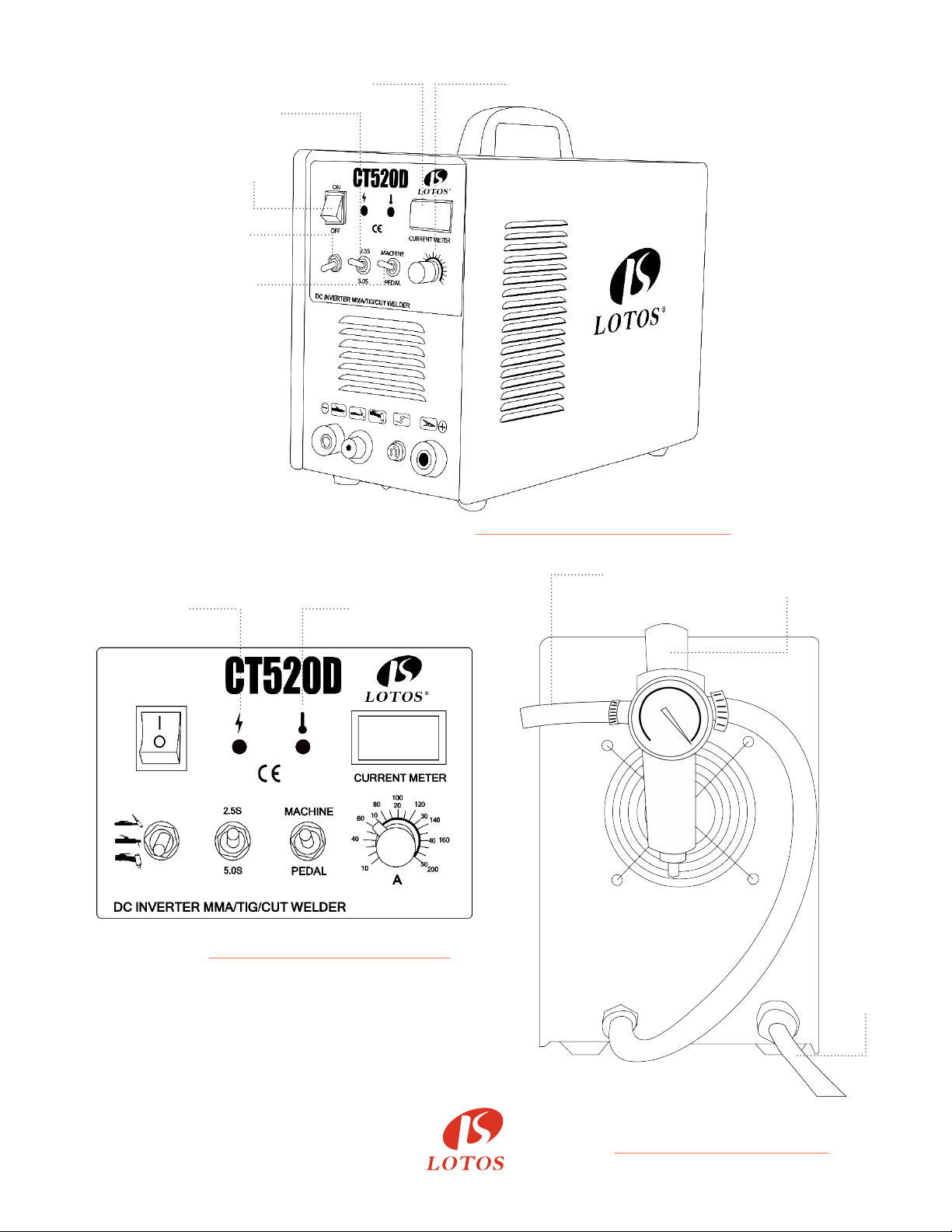
Figure 2.1: Adjustor Diagram 1
Figure 2.2: Adjustor Diagram 2
Figure 2.3:
Air Regulator Conguraon
12
Amp Display
Amp Adjusting
2-step &
5-step Switch
Machine/
Pedal Switch
Function
Switch
Problem
Indicator
Connect to
Air Compressor
Air
Regulator
Power
Cord
Power
Switch
(TIG)
(Stick)
(Cutter)
Problem
Indicator
®
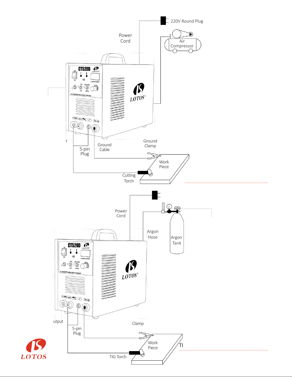
Figure 2.4:
Plasma Cung Diagram
Figure 2.5:
TIG Welding without Foot Pedal Diagram
13
Power
Cord
Adjust to
Plasma Cut
Output
Output
5-pin
Plug
5-pin
Plug
Ground
Cable
Ground
Clamp
Clamp
Work
Piece
Work
Piece
Cutting
Torch
TIG Torch
220V Round Plug
220V Round Plug
Air
Compressor
Argon
Tank
Argon
Hose
Argon
Regulator
Power
Cord
Gas & Power
Gas & Power
Ground
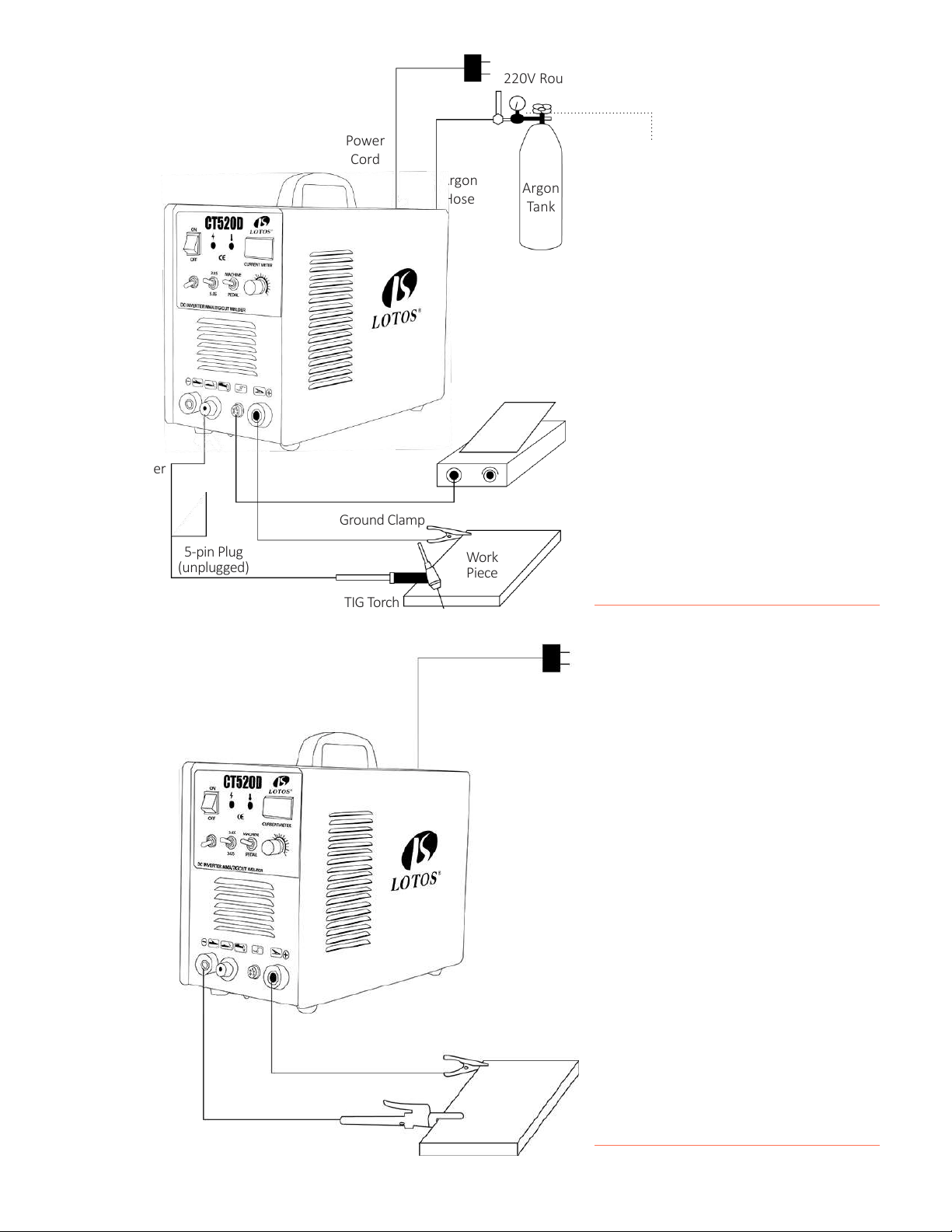
Figure 2.7:
Arc/Sck/MMA Welding Diagram
Figure 2.6:
TIG Welding with Foot Pedal Diagram
14
220V Round Plug
Argon
Tank
Argon
Regulator
Argon
Hose
Power
Cord
Gas & Power
Output
5-pin Plug
(unplugged)
Foot Pedal with
5-pin Plug
Work
Piece
Ground Clamp
TIG Torch
220V Round Plug
Work
Piece
Ground Clamp (+)
Arc Handler (-)
Ground Clamp (+)
Work
Piece

®
INSTALLATION
Connect this welding & cung equipment with a power supply of 110 or 220V AC.
For 110VAC,
- The green wire with yellow stripe is the ground wire
- The red/brown wire is the hot wire
- The blue/black wire is the neutral wire
For 220VAC,
- The green wire with yellow stripe is the ground wire
- The red/brown wire is posive 220VAC
- The blue/black wire is negave 220VAC
Connect the earth terminal with the earth cable (minimum diameter of 2.5 mm
2
.)
1. Install welding torch according to the quick setup guide.
2. Connect the one-knob connector, air plug to the corresponding connector on the panel
board; and fasten the screw.
3. Plug the air plug of the back cable to “+” of the air socket on the panel board; and fasten it in
clockwise. Connect earth clamp with work piece.
If the power switch is on, the built-in fan starts working and the current meter displays the
current value.
The funcon switch enables the machine to alternate between MMA, TIG, and CUT welding
according to the praccal welding task requirement.
1. TIG Welding Funcon
- Connect the copper nozzle in the back of the machine to the argon tank with the hose. The
gas supply system includes the gas bole, air regulator, and gas hose. Connect the parts of the
gas system rmly to prevent gas leakage.
- Install the argon torch according to the Figure 3.2.
- Connect the copper screw on the cung torch to the output terminal of the one-knob of the
front panel; and fasten it clockwise to avoid gas leakage.
- Connect the plug of the closed circuit to the “+” socket on the panel board. Connect the earth
clamp to the work piece.
Funcon Switch
Power Cord Plug Wiring
Connecon of the Output Cables
Power Supply Switch
15
®
Funcon Switch
Welding Current Output Seng
Air/Argon Regulator Installaon
2. MMA Funcon
- Connect the plug of the electrode holder to the “+” socket on the front panel.
- Connect the plug of the ground clamp to the “-” socket on the front panel.
3. Plasma Cung Funcon
- Use the gas hose to connect to one of the terminals on the air regulator and connect the
other terminals to the copper tub.
- Connect the copper nut of the cung torch to the knob on the panel board. Connect the plug
of the ground clamp to the “-”socket on the front panel.
Based on your applicaon, set the current output to “ARC,” “TIG,” or “CUT.”
16
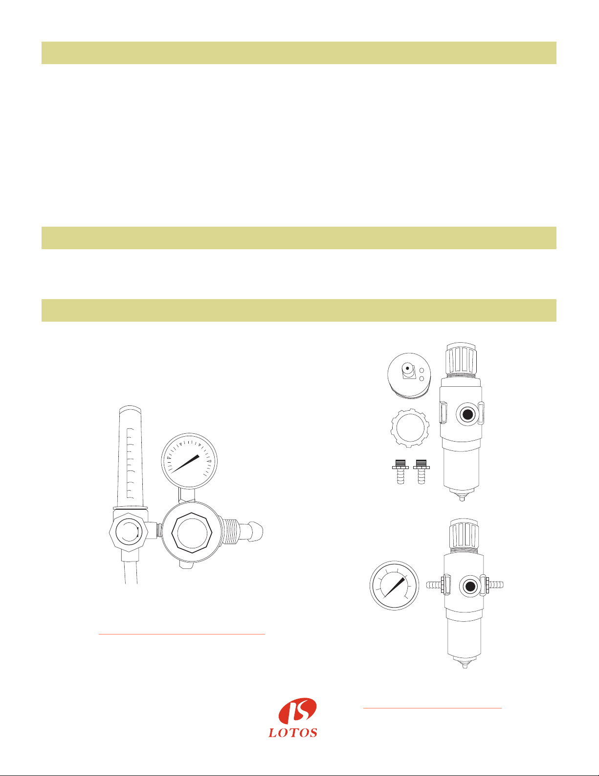
25
20
15
10
5
1
SHUT
REGULATOR
AR
OPEN
Figure 3.1:
Gas Regulator Installaon
Figure 3.2:
Argon Installaon
(Unassembled)
(Assembled)
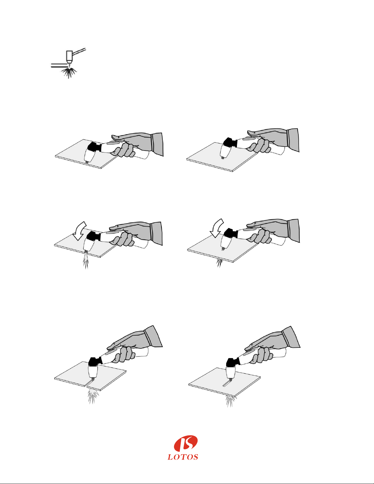
Tips For Cutting
1. Hold the torch at an approximate 30° to the workpiece, let the copper tip directly
contact with the workpiece.
2. Fire the torch. Slowly rotate the torch to from 30° to 90°.
3. Hold the torch in place while continuing to press the trigger. When the arc goes
completely through the workpiece, then the arc has pierced the material.
CAUTION: If cutting functions improperly, try to remove oxidization of the electrode on the
torch with sand paper.
®
17

®
OPERATION
TIG Welding Funcon
1) While this welding & cung equipment is operated, the power supply indicator is on; and
the built-in fan will funcon.
2) Switch to the TIG welding funcon mode.
3) Press the gas release buon and modulate the volume of gas output to the required value.
4) Press the buon on the welding torch, and the electromagnec valve funcons. The sound
of releasing electricity is audible, and there is gas coming out of the welding torch.
Please note: Before the inial welding operaon, press the welding torch buon for several
seconds in order to remove the gas inside the gas tub, and the welding operaon can begin.
There is gas output within a few seconds aer the welding operaon. It is a special design
to protect the welding point before it cools down. Therefore, aer the arc is gone, maintain
the welding posion unl the heat produced during the welding operaon dissipates.
18
MMA Funcon
1) Switch to MMA welding mode.
2) While this welding & cung equipment is operated, the power supply indicator is on and
the built-in fan will funcon.
3) According to the thickness of the work piece, adjust the welding current output and choose
the rod, then the MMA welding can begin.
5) The welding current output is adjustable, according to the thickness of the welding material
and required crasmanship.
6) Maintain a distance of 1-4mm between the tungsten electrode and the work piece. Press the
welding torch buon. HF electricity will release between the welding electrode and the work
piece. Aer the arc starts, the splash of the HF arc will vanish and the welding operaon can
begin.

®
1) Switch to the plasma-cung mode.
2) While this welding & cung equipment is operated, the power supply indicator is on and
the built-in fan will funcon.
3) Release the regulator valve, and modulate the pressure and volume of output gas.
4) Press the cung torch buon. The sound of releasing electricity is audible and there is gas
coming out of the welding torch.
5) According to the thickness of the work piece, adjust the current output, and then the
plasma cung can begin.
6) Put the nozzle of the cung torch to the work piece and press the welding torch buon.
The sound of the HF arc vanishes and the cung operaon can begin. Aer the arc starts,
maintain a distance of about 1mm in order to protect the nozzle from possible damage.
7) In case of diculty with starng the arc, it is recommended to reduce the pressure of the
gas output.
8) If the nozzle is damaged, adjust the pressure of the gas output.
Plasma Cung Funcon
19

®
Instruction Notes
1. The locaon in which this welding & cung equipment is installed should be free of dust, corrosive
chemical gases, ammable gases or materials, and of be at no more than 80% humidity.
2. Avoid welding & cung in the open air unless sheltered from the sun, rain, and snow.
The temperature of the working environment should be maintained within -10°C to +40°C.
3. Keep this welding & cung equipment 30cm away from the wall.
4. Ensure the working environment has good venlaon.
a) Venlaon
This welding & cung equipment is small, compact in structure, and has excellent current output
performance. Fans are required to remove heat generated by this cung equipment while the machine
is being operated.
Cauons: Maintain good venlaon of the louvers of this welding & cung equipment. The minimum
distance between this welding & cung equipment and any other object in or near the working area
should be 30 cm. Good venlaon is of crical importance for the normal performance and service life
of this welding & cung equipment.
b) Welding cannot be performed if equipment is overloaded.
A sudden halt may occur while the cung operaon is carried out if the machine is in over-load status.
Under this circumstance, it is unnecessary to restart the equipment. Keep the built-in fan running to
bring down the temperature inside the equipment.
c) Beware of over-voltage.
Regarding the power supply voltage range of the welding & cung machine, please refer to the
“Specicaons” table. This equipment has automac voltage compensaon, which enables it to maintain
the voltage within the given range. If the power supply input voltage current exceeds the spulated
value, it is possible to damage the components of this equipment.
d) An earth terminal is available for this welding & cung equipment.
Connect the earth cable to avoid stac and electric shock. It is not recommended to touch the output
terminal while welding and cung. An electric shock may occur.
Safety
Working Environment
20

®
Maintenance
Troubleshoong
Exposure to extremely dusty, damp, or corrosive air is damaging to this welding & cung machine.
In order to prevent any possible failure or fault of this equipment, clean the dust out at regular intervals
with clean and dry compressed air of required pressure.
Please note: Lack of maintenance can lead to the unavailability and cancellaon of the guarantee;
the guarantee of this equipment will no longer be available if aempts have been made to take the machine
apart or the factory-made sealing of the machine has been opened.
The following trouble shoong guide is for your reference only. Lotos Technology will NOT take any liability
or responsibility for any injury or damage caused in such acon(s). Always turn o electrical power and air
supply before performing inspecon and reconnecon.
CAUTIONS: Only qualied technicians are authorized to undertake the repair of this equipment in the case
of machine failure.
Fault Symptoms Rectication
1. While this welding and cutting
equipment is off,
the built-in fan is not functioning,
and there is no output.
1. Possible damage of power supply switch; fix the damage if necessary.
2. Possible unavailability of power supply. Check for failure in power
supply.
3. Possible short-circuit of the input cable. Check it and repair it if
necessary.
2. While this welding and cutting
equipment is on,
the pilot lamp is on,
no output,
built-in fan unavailable.
1. Possible misconnection with input of 380V, and occurrence
of over voltage protection status. Reconnect with input of
220V, and restart.
2. Possible unstable input due to the unavailable input cable or
possible connection unavailable spells it's being of over-voltage
protection status.
3. Frequently switching on and off of this welding equipmentin
a short period leads this equipment's being of over-voltage
protection. Switch off this welding machine and wait for at
least 3 minutes, then restart this welding equipment.
4. Possible unavailable of the connection of switch and bottom
PCB. Reconnect it.
5. The 24V relay of bottom PCB is possibly damaged. Replaced
it if necessary.
21

®
Fault Symptoms Rectication
3. While this equipment is on,
the built-in fan functions,
the fault indicator is off,
no HF electricity releasing,
arc does not start.
1. The normal voltage of positive and negative pole of board
VH-07 should be DC 380V.
1.1 Possible short circuit, and possible misconnection of silicon
bridge with the PCB.
1.2 Possible electricity leakage of capacitors; replace them if
necessary.
2. The green light indicator of secondary power supply of top PCB
should be on. Otherwise, it indicates that the secondary power
supply is not functioning. Check whether the connection is
available. If fault cannot be rectified, please contact supplier for
further advice.
3. Possible unavailability of connection inside the equipment.
Check and reconnect if necessary.
4. Possible malfunction of control circuit. Check and contact the
supplier for further advice.
5. Possible damage of the welding torch. Replace it if necessary.
4. While this equipment is on,
fault indicator is off,
HF electricity is releasing,
and welding current output is unavailable.
1. Possible disconnection of welding torch cable.
2. Possible disconnection of earth cable, or misconnection of the
earth cable and work piece.
3. The connection between positive output terminal or the gas or
electricity output terminal and this welding equipment is possibly
unavailable. Reconnect them if necessary.
5. While this equipment is on,
the fault indicator is off, no electricity
releasing, and arc starts.
1. The cable connection between the transformer of arc starting
and power PCB is possibly unavailable. Check and reconnect it.
2. Possible oxidization of electricity releasing parts or the
distance is larger than the maximum distance allowed. Remove
the oxidization of the electricity releasing parts and adjust the
distance of the electricity releasing parts to range of 1mm.
3. Possible damage to MMA/TIG switch. Replace them if
necessary.
4. Components of HF arc starting circuit are possibly damaged.
Check and replace them if necessary.
6. While this equipment is on,
the fault indicator is on,
and there is no output.
1. It is possible the machine is in over-current protection status.
Switch off the power supply, wait until the fault indicator is off,
and restart the welding equipment.
2. It is possible the machine is in over-heating protection status.
Wait until the fault indicator is off, and the welding operation can
begin.
3. Possible damage of feed-back circuit. Compensate the fault if
necessary.
22

®
Fault Symptoms Rectication
7. Unstable current output during the
welding operation, and the potentiometer
is unavailable.
1. Possible damage of 1K resistance. Replace it if necessary.
2. The connection of this welding equipment is not available.
8. Excessive splash generated during
welding operation. It is difficult to weld
with alkaline rod.
1. Misconnection of earth cable and welding torch cable.
2. Reconnect them.
9. Insufficiency in welding and cutting
performance, and the arc is not stable.
1. Possible insufficiency of voltage input.
2. The connection of earth cable is unavailable. Reconnect it.
3. The gas supply system is unavailable. Examine it and fix it if
necessary.
4. There is possible deficiency of electrode of cutting torch.
5. The filter capacitor of this welding and cutting equipment is
not
available. Replace it if necessary.
6. The rod is not available due to the fact that the rod has
become
damp or damaged.
7. The current is not available to start the arc.
23