Loading ...
Loading ...
Loading ...

Product Overview & Features
17
SSL UC1 User Guide
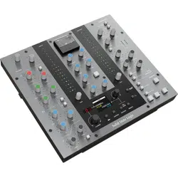
Central Control Panel
The Central Control Panel of UC1 is used to perform a number of key functions relating to the plug-ins and the Plug-in Mixer.
1 - 7-Segment Display
Displays the position of the selected Channel Strip 2 plug-in in the Plug-in Mixer.
2 - CHANNEL Encoder
Changes the selected Channel Strip 2 plug-in being controlled by UC1.
3 - Channel Strip Name
Displays the name of the DAW track the Channel Strip 2 plug-in is inserted on in the DAW. Immediately below, a value readout is
temporarily displayed whilst a Channel Strip control is being adjusted.
4 - Bus Compressor Name
Displays the name of the DAW track the Bus Compressor 2 plug-in is inserted on in the DAW. Immediately below, a value readout
is temporarily displayed whilst a Bus Compressor control is being adjusted.
5 - SECONDARY Encoder
By default this control changes the selected Bus Compressor but it can also be used to change the process order for Channel Strip
2, or it can be used to scroll through presets and select them for either Channel Strips or Bus Compressors.
6 - BACK Button
Used to navigate back up through the PRESETS list.
7 - CONFIRM Button
Used to navigate forward through the PRESETS list and also confirms the preset for loading.
8 - ROUTING Button
Allows the SECONDARY encoder to change the processing routing order of the selected Channel Strip 2 plug-in.
9 - PRESETS Button
Allows the SECONDARY encoder to load a preset for the selected Channel Strip 2 or Bus Compressor 2 plug-in.
3
5
4
6 7 8 9
10
11
1
2
Loading ...
Loading ...
Loading ...