Loading ...
Loading ...
Loading ...
5
6
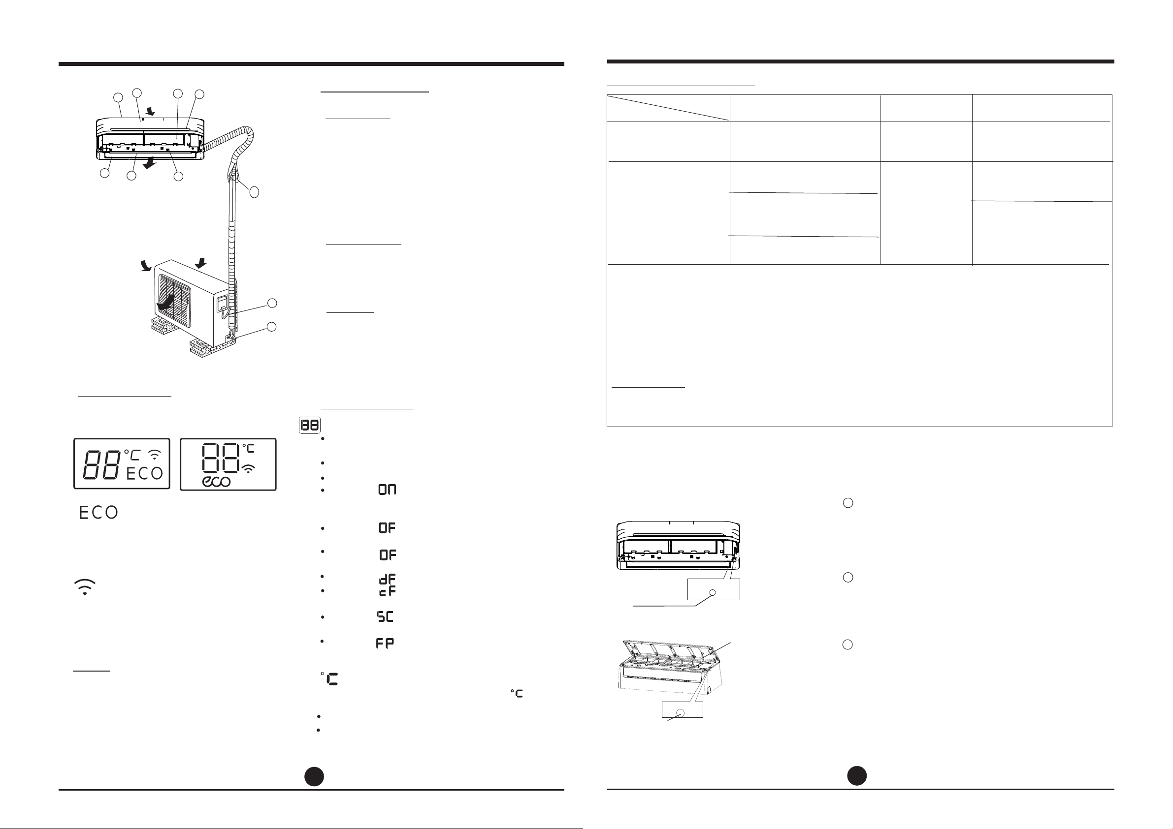
NAMES OF PARTS
OPERATING INSTRUCTIONS
8. Connecting
9. Connecting cable
10. Stop valve
pipe
Outdoor unit
Display window
Display window
The display window of indoor unit
may look like one of the following:
NOTE:
All the pictures in this manual are for
explanation purposes only. The actual shape
of the indoor unit you purchased may be
slightly different on front panel and display
window. The actual shape shall prevail.
Air inlet(rear)
Air inlet(side)
Air inlet
Air outlet
Air outlet
1. Front panel
2. Air inlet
3. Air filter
4. Air outlet
5. Horizontal air flow grille
6. Vertical air flow louver(inside)
7. Display window
Indoor unit
Names of parts
4
3
5
2
6
8
1
9
10
7
NOTE:
A guide on using the infrared remote
is not included in this literature package.
Units are equipped with a switch to run emergency operation mode. It can be accessed by
opening the front panel. This switch is used for manual operation in case the remote controller
fails to work or maintenance necessary.
Manual operation
Operating temperature
Manual switch
AUTO/COOL
This switch is used for testing purposes
only. Please do not use it unless necessary.
To restore the remote controller operation,
use the remote controller directly.
CAUTION:
●
●
Digital display:
Displays the temperature settings when the
air conditioner is operational.
Displays the room temperature in FAN mode.
Displays the self-diagnostic codes.
Displays for three seconds when Timer
ON, Fresh, Swing, Turbo or Silence feature is
activated.
Displays for three seconds when Timer
OFF is set.
Displays for three seconds when Fresh,
Swing, Turbo or Silence feature is cancelled.
Displays under defrosting operation.
Displays when anti-cold air feature is
activated under heating mode.
Displays during self clean operation(if
applicable).
O
Displays under 8 C heating operation(if
applicable).
,
,
,
,
,
,
,
,
,
,
,
,
,
,
Energy saving display(optional):
Wireless control display(optional):
Displays when the energy saving
feature is activated.
Displays when the Wireless control
feature is activated.
According to the operation mode, the
indicator displays different colour:
Under Cool or Dry mode, it displays as cool colour.
Under Heat mode, it displays as warm colour.
,,
,,
(Optional)
Suspension bars
AUTO/COOL
(1)
(2)
Manual switch
Open the front panel by carefully lifting
both ends at the same time. Once lifted
sufficiently, a click is heard and it becomes
self-supporting. For some models, please
use suspension bars to prop up the panel.
After operation, close the panel by firmly
tugging downwards on both ends until it
returns to its original position.
One press of the manual control switch will
lead to the forced AUTO operation. If press
the switch twice within five seconds, the unit
will operate under forced COOL operation.
1
3
2
Mode
Cooling operation
Heating operation
Drying operation
Temperature
1. Optimum performance will be achieved within these operating temperatures. If air
conditioner is used outside of the above conditions, certain safety protection features
might come into operation and cause the unit to function abnormally.
2. Room relative humidity less than 80%. If the air conditioner operates in excess of this
figure, the surface of the air conditioner may attract condensation. Please sets the vertical
air flow louver to its maximum angle (vertically to the floor), and set HIGH fan mode.
Suggestion: For the unit adopts an Electric Heater, when the outside ambient temperature
O O
is below 0 C(32 F), we strongly recommend you to keep the machine plugged in order to
guarantee it running smoothly.
Room temperature
Outdoor temperature
NOTE:
( For the models with low
temperature cooling system
(For special tropical models)
(For special tropical models)
O O
17 C~32 C
O O
(62 F~90 F)
O O
0 C~30 C
O O
(32 F~86 F)
O O
0 C~50 C
O O
(32 F~122 F)
O O
0 C~50 C
O O
(32 F~122 F)
O O
-15 C~30 C
O O
(5 F~86 F)
O O
-15 C~50 C/5 )
O O
F~122 F
O O
0 C~60 C/32 )
O O
F~140 F
O O
0 C~60 C/32 )
O O
F~140 F
O O
10 C~32 C
O O
(50 F~90 F)
Loading ...
Loading ...
Loading ...