9.801-191.0 - D (04/21)
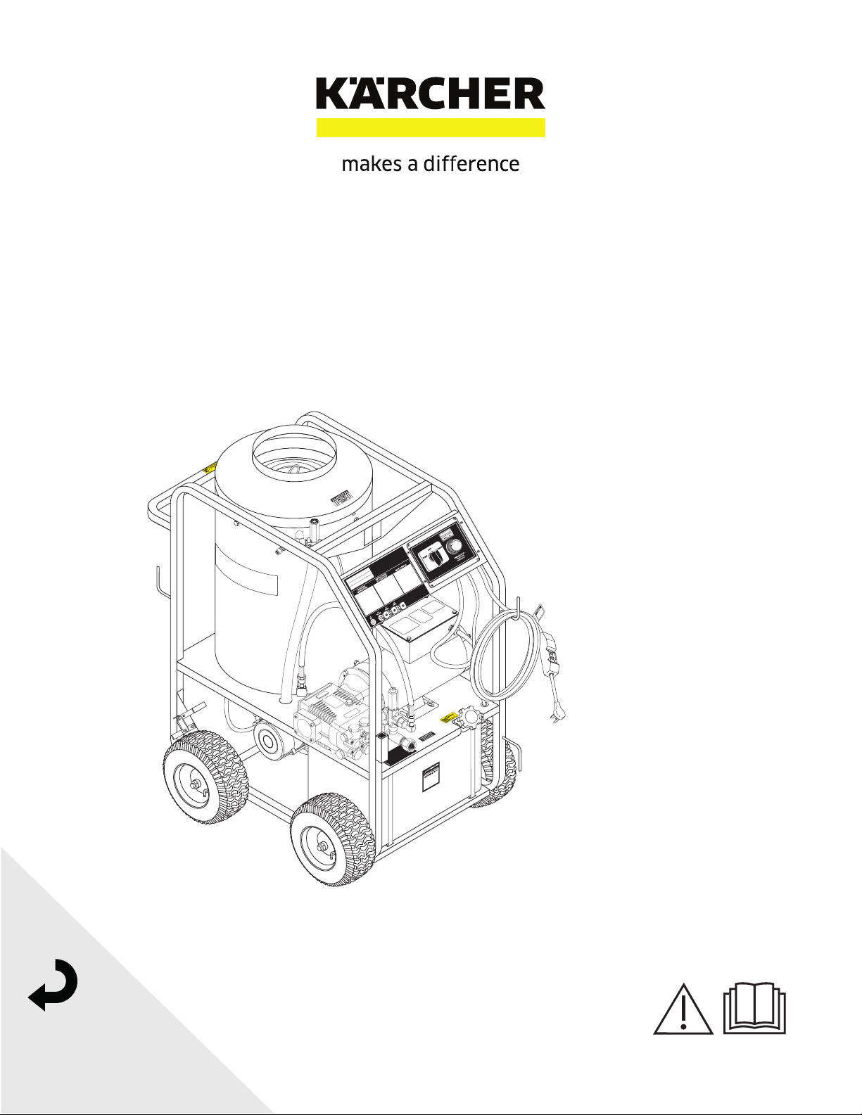
High pressure cleaner
Electric motor - Hot water
Register
your product
www.kaercher.com/welcome
English..... 2
MODELS:
1.109-101.0
STP-231007D
1.109-102.0
STP-201507D
1.109-103.0
STP-352007A
1.575-513.0
STP-231007D
1.109-133.0
STP-231007D
1.109-134.0
STP-352007A

CONTENTS
2
Model Number ______________________________
Serial Number ______________________________
Date of Purchase ____________________________
The model and serial numbers will be found on a decal attached
to the pressure washer. You should record both serial number and
date of purchase and keep in a safe place for future reference.
Manual Karcher STP 9.801-191.0 - D
Introduction and Safety Information 3-5
Component Identification 6
Operating Instructions 7-8
Preventative Maintenance and Service 9-11
Exploded Views 12-13
Exploded Views Parts List 14-15
Control Panel Exploded View and Parts List 16
Hose & Spray Gun Assembly and Parts List 17
VBT Unloader Exploded View and Parts List 18
Pump Exploded View and Parts List 19-20
Burner Clear Flame Exploded View and Parts List 21-22
Troubleshooting 23
Maintenance Schedule 24
Manual Karcher STP 9.801-191.0 - D
3
PRESSURE WASHER
OPERATOR’S MANUAL
Thank you for purchasing this Pressure Washer.
We reserve the right to make changes at any time
without incurring any obligation.
Owner/User Responsibility:
The owner and/or user must have an understanding of
the manufacturer’s operating instructions and warnings
before using this pressure washer. Warning information
should be emphasized and understood. If the operator
is not fluent in English, the manufacturer’s instructions
and warnings shall be read to and discussed with
the operator in the operator’s native language by the
purchaser/owner, making sure that the operator com-
prehends its contents.
Owner and/or user must study and maintain for future
reference the manufacturers’ instructions.
The operator must know how to stop the machine
quickly and understand the operation of all controls.
Never permit anyone to operate the engine without
proper instructions.
SAVE THESE INSTRUCTIONS
This manual should be considered a permanent
part of the machine and should remain with it if
machine is resold.
When ordering parts, please specify model and
serial number. Use only identical replacement parts.
This machine is to be used only by trained operators.
IMPORTANT SAFETY
INFORMATION
READ OPERATOR’S
MANUAL THOROUGHLY
PRIOR TO USE.
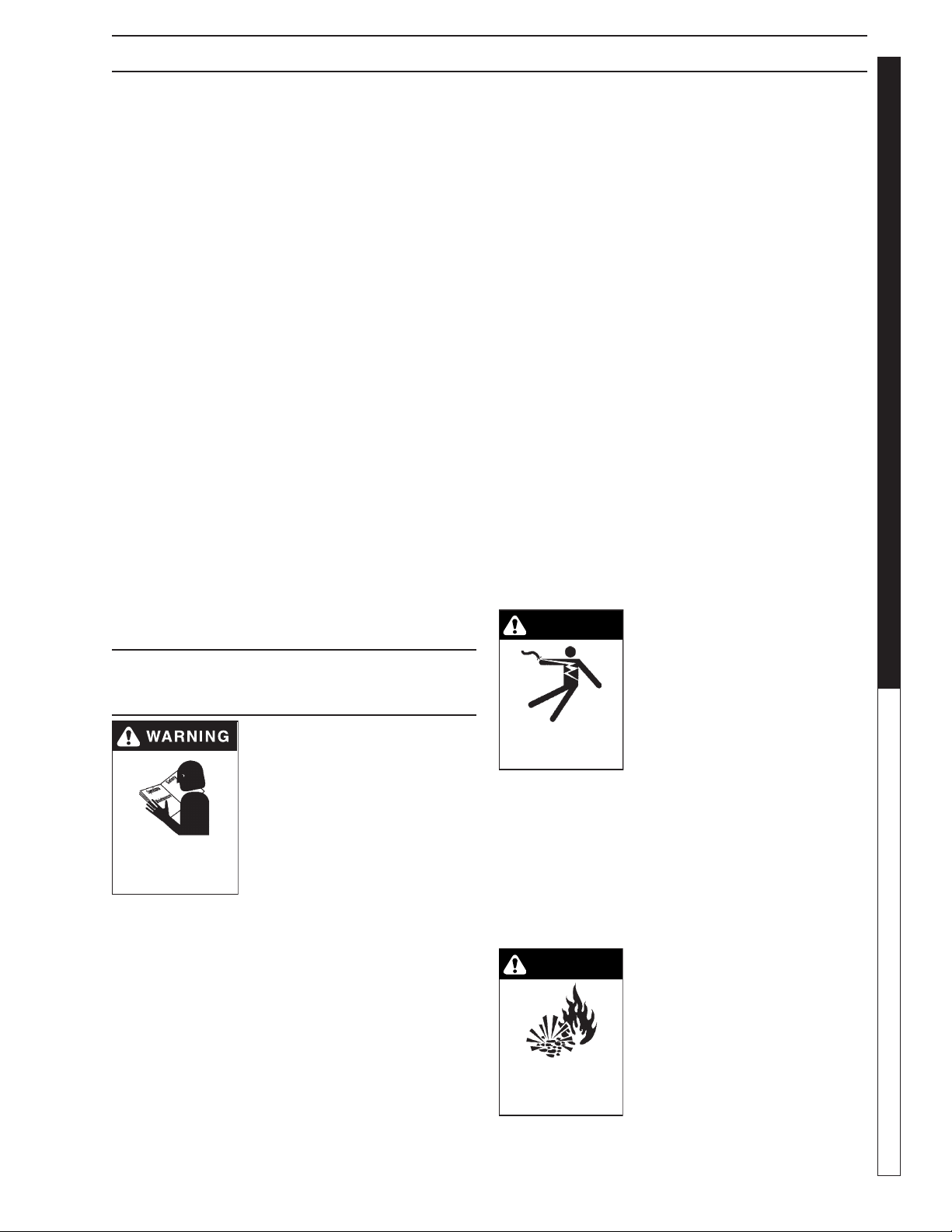
WARNING: To reduce the risk of
injury, read operating instruc-
tions carefully before using.
AVERTISSEMENT: Pour réduire
le risque de blessures, lire
attentivement les instruc-
tions de fonctionnement avant
l'utilisation.
1. Read the owner's manual thor-
oughly. Failure to follow instructions could cause
malfunction of the machine and result in death,
serious bodily injury and/or property damage.
2. Know how to stop the machine and bleed pressure
quickly. Be thoroughly familiar with the controls.
3. Stay alert — watch what you are doing.
4. All installations must comply with local codes.
Contact your electrician, plumber, utility company
or the selling distributor for specific details. If your
machine is rated 250 volts or less, single phase will
be provided with a ground fault circuit interrupter
(GFCI). If rated more than 250 volts, or more than
single phase this product should only be connected
to a power supply receptacle protected by a GFCI.
INTRODUCTION & IMPORTANT SAFETY INFORMATION
DANGER: Improper connection of the equipment-
grounding conductor can result in a risk of elec-
trocution. Check with a qualified electrician or
service personnel if you are in doubt as to whether
the outlet is properly grounded. Do not modify the
plug provided with the product - if it will not fit the
outlet, have a proper outlet installed by a qualified
electrician. Do not use any type of adaptor with
this product.
DANGER: Ne pas mettre d’antimousse, de solvants,
de détacheur ou de produits chimiques de prépul-
vérisation dans le réservoir à solution. Ne pas lais-
ser l’eau se déverser dans l’entrée du moteur de
l’aspirateur. Essuyer tout écoulement dans le haut
du réservoir à solution avant de remettre le réser-
voir de récupération en place. NE JAMAIS utiliser
un adaptateur avec ce produit.
WARNING: Must be plugged into properly wired
three hole grounded outlet that accommodates
plug on power cord. Failure to comply could result
in electrical shock.
AVERTISSEMENT: Doit être raccordé dans une
sortie à trois trous mise à la masse et correctement
câblée qui peut accueillir une fiche sur un cordon
d'alimentation. Le non-respect de cette consigne
pourrait causer un choc électrique.
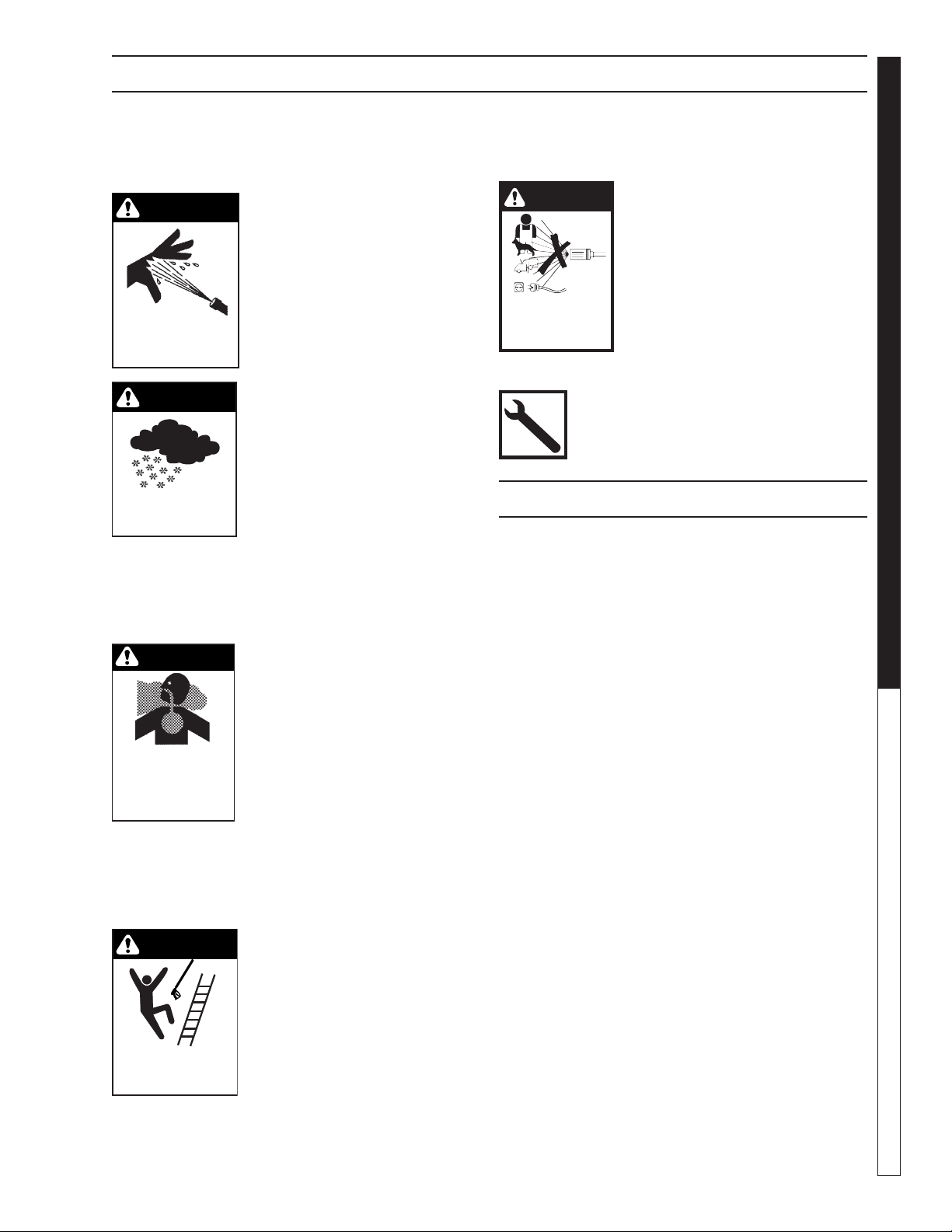
WARNING
KEEP WATER
SPRAY AWAY FROM
ELECTRICAL WIRING.
WARNING: Keep wand, hose, and
water spray away from electric
wiring or fatal electric shock may
result.
AVERTISSEMENT: Garder la
lance, le boyau et le jet d'eau à
l'écart de tout câblage électrique
ou des chocs électriques mor-
tels pourraient survenir.
5. To protect the operator from electrical shock,
the machine must be electrically grounded.
It is the responsibility of the owner to connect this ma-
chine to a UL grounded receptacle of proper voltage
and amperage ratings. Do not spray water on or near
electrical components. Do not touch machine with wet
hands or while standing in water. Always disconnect
power before servicing.
RISK OF EXPLOSION:
OPERATE ONLY WHERE
OPEN FLAME OR TORCH
IS PERMITTED
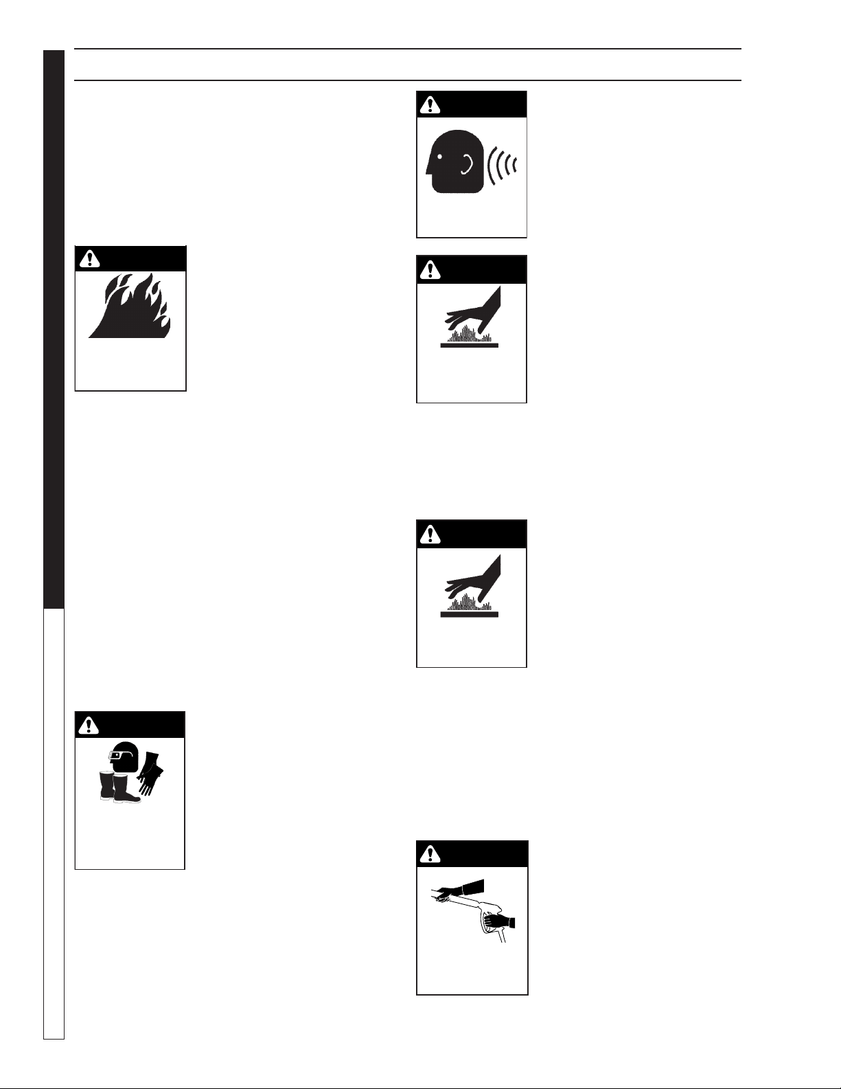
WARNING
WARNING: Flammable liquids
can create fumes which can ig-
nite, causing property damage
or severe injury.
AVERTISSEMENT: Des liquides
inflammables peuvent produire
des vapeurs qui peuvent
s'enflammer, causant ainsi des
dommages à la propriété ou des
blessures graves.
Manual Karcher STP 9.801-191.0 - D
OPERATOR’S MANUAL
PRESSURE WASHER
4
IMPORTANT SAFETY INFORMATION
WARNING: Risk of explosion Operate only where
open flame or torch is permitted.
AVERTISSEMENT: Risque d'explosion. Utiliser
uniquement dans des endroits où l'utilisation d'une
flamme nue ou d'une torche est permise.
6. In oil burning models, use only kerosene, No. 1
home heating fuel, or diesel. If diesel is used, add
a soot remover to every tankful.
RISK OF FIRE.
DO NOT ADD FUEL
WHEN OPERATING
MACHINE.
WARNING
WARNING: Risk of fire — Do not
add fuel when the product is
operating or still hot.
AVERTISSEMENT: Risque
d'incendie — Ne pas ajouter de
carburant pendant que la ma-
chine fonctionner ou est encore
chaude.
WARNING: Do not use gasoline crankcase draining
or oil containing gasoline, solvents or alcohol. Do-
ing so will result in fire and/or explosion.
AVERTISSEMENT: Ne pas utiliser d'essence, de
drainage du carter de moteur ou d'essence con-
tenant de l'huile, de solvants ou de l'alcool. Agir
de la sorte risquerait de créer un incendie et/ou
une explosion.
7. Oil burning appliances shall be installed only in
locations where combustible dusts and flammable
gases or vapors are not present. Do not store or
use gasoline near this machine.
8. Do not allow acids, caustic or abrasive fluids to pass
through the pump.
9. Never run pump dry or leave spray gun closed
longer than 1-2 minutes.
10. Keep operating area clear of all persons.
WARNING
USE PROTECTIVE
EYE WEAR
AND CLOTHING
WHEN OPERATING
THIS EQUIPMENT.
WARNING: High pressure spray
can cause paint chips or other
particles to become airborne
and fly at high speeds. To avoid
personal injury, eye, hand and
foot safety devices must be
worn.
AVERTISSEMENT: Un jet haute
pression peut écailler la peinture
ou provoquer l'émission d'autres
particules dans l'air et leur projection à hautes
vitesses. Pour éviter les lésions corporelles, une
protection des yeux, du visage, des mains et des
pieds doit être
11. Eye, hand, and foot protection must be worn when
using this equipment.
WARNING: This machine ex-
ceeds 85 db appropriate ear
protection must be worn.
AVERTISSEMENT: Cette ma-
chine excède 85 dB et une pro-
tection de l'ouïe appropriée doit
être portée.
WARNING: Hot discharge fluid.
Do not touch or direct discharge
stream at persons.
AVERTISSEMENT: Liquide de
décharge chaud. Ne pas toucher
ou décharger directement le
jet vers des personnes ou des
animaux, car cela risquerait de
causer des blessures graves ou
même la mort.
WARNING: This machine produces hot water and
must have insulated components attached to pro-
tect the operator.
AVERTISSEMENT: Cette machine produit de l'eau
chaude et doit comporter des composants isolés
attachés pour protéger l'opérateur.
WARNING: Risk of injury. Hot
surfaces can cause burns. Use
only designated gripping areas
of spray gun and wand. Do not
place hands or feet on non-
insulated areas of the pressure
washer.
AVERTISSEMENT: Risque
d'injection ou de blessures. Les
surfaces chaudes peuvent causer des brûlures.
Utiliser uniquement les zones de prise désignées du
pistolet pulvérisateur et de la lance. Ne pas placer
les mains ou les pieds sur des endroits non isolés
de la laveuse à pression.
12. To reduce the risk of injury, close supervision is nec-
essary when a machine is used near children. Do
not allow children to operate the pressure washer.
This machine must be attended during opera-
tion.
WARNING: Grip cleaning wand
securely with both hands before
starting. Failure to do this could
result in injury from a whipping
wand.
AVERTISSEMENT: Agripper
la lance de nettoyage avec
les deux mains avant de com-
mencer. Le non-respect de cette
consigne pourrait mener à des blessures causées
par le mouvement violent de la lance.
WARNING
EAR PROTECTION
MUST BE WORN
WARNING
HOT DISCHARGE FLUID:
DO NOT TOUCH OR
DIRECT DISCHARGE
STREAM AT PERSONS.
WARNING
RISK OF INJURY:
HOT SURFACES
CAN CAUSE BURNS
TRIGGER GUN KICKS
BACK - HOLD WITH
BOTH HANDS
WARNING
Manual Karcher STP 9.801-191.0 - D
5
PRESSURE WASHER
OPERATOR’S MANUAL
13. Never make adjustments on machine while in op-
eration.
14. Be certain all quick coupler fittings are secured
before using pressure washer.
RISK OF INJECTION
OR SEVERE INJURY
TO PERSONS. KEEP
CLEAR OF NOZZLE.
WARNING
WARNING: High pressure devel-
oped by these machines will
cause personal injury or equip-
ment damage. Keep clear of
nozzle. Use caution when oper-
ating. Do not direct discharge
stream at people, or severe in-
jury or death will result.
WARNING
PROTECT FROM
FREEZING
WARNING: Protect machine from
freezing.
15. To keep machine in best
operating conditions, it is
important you protect machine
from freezing. Failure to protect
machine from freezing
could cause malfunction of the
machine and result in death,
serious bodily injury, and/or property damage. Fol-
low storage instructions specified in this manual.
16. Inlet water must be clean fresh water and no hotter
then 90°F.
WARNING
RISK OF
ASPHYXIATION: USE
THIS PRODUCT ONLY
IN A WELL
VENTILATED AREA.
WARNING: Risk of asphyxiation.
Use this product only in a
well ventilated area.
17. Avoid installing machines in
small areas or near exhaust
fans. Adequate oxygen is need-
ed for combustion or dangerous
carbon monoxide will result.
18. Manufacturer will not be
liable for any changes made
to our standard machines or any components not
purchased from us.
19. The best insurance against an accident is precau-
tion and knowledge of the machine.
WARNING
RISK OF INJURY FROM
FALLS WHEN USING
LADDER.
WARNING: Be extremely careful
when using a ladder, scaffolding
or any other relatively unstable
location. The cleaning area
should have adequate slopes
and drainage to reduce the pos-
sibility of a fall due to slippery
surfaces.
20. Do not overreach or stand on unstable support.
Keep good footing and balance at all times.
IMPORTANT SAFETY INFORMATION
21. Do not operate this machine when fatigued or under
the influence of alcohol, prescription medications,
or drugs.
WARNING
DO NOT SPRAY
MACHINE OR ANY
PEOPLE, ANIMALS OR
ELECTRICAL PARTS.
WARNING: Do not spray machine
or any people, animals or electri-
cal parts.
AVERTISSEMENT:
Ne pas va-
poriser sur la machine ou les
gens, les animaux ou les pi
èces
électriques.
Follow the maintenance instructions
specified in the manual.
INSTALLATION
Place machine in a convenient location providing ample
support, draining and room for maintenance.
This machine is intended for indoor use. Machine
must be stored indoors when not in use.
Location:
The location should protect the machine from damag-
ing environmental conditions, such as wind, rain, and
freezing.
1. This machine should be run on a level surface
where it is not readily influenced by outside
sources such as strong winds, freezing tem-
perature, rain, etc. It should be located to allow
accessibility for refilling of fuel, adjustments, and
maintenance. Normal precautions should be
taken by the operator of the machine to prevent
moisture from reaching the electrical controls.
2. It is recommended that a partition be made
between the wash area and the machine to pre-
vent water spray from coming in contact with the
machine. Excess moisture reaching any electric
components or electrical controls will reduce
machine life and may cause electrical shorts.
3. During installation of the machine, beware of
poorly ventilated locations or areas where ex-
haust fans may cause an insufficient supply of
oxygen. Sufficient combustion can only be ob-
tained when there is a sufficient supply of oxygen
available for the amount of fuel being burned. If
it is necessary to install a machine in a poorly
ventilated area, outside fresh air may have to be
piped to the burner and a fan installed to bring
air into the machine.
Avoid small locations or areas near exhaust fans.
Manual Karcher STP 9.801-191.0 - D
OPERATOR’S MANUAL
PRESSURE WASHER
6
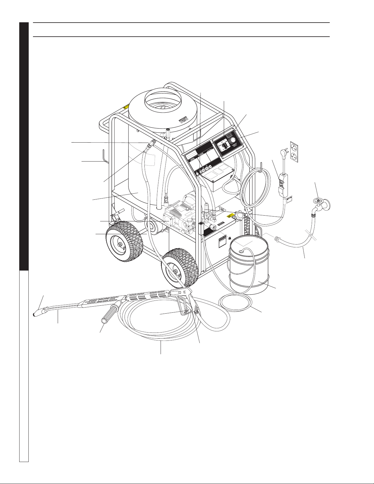
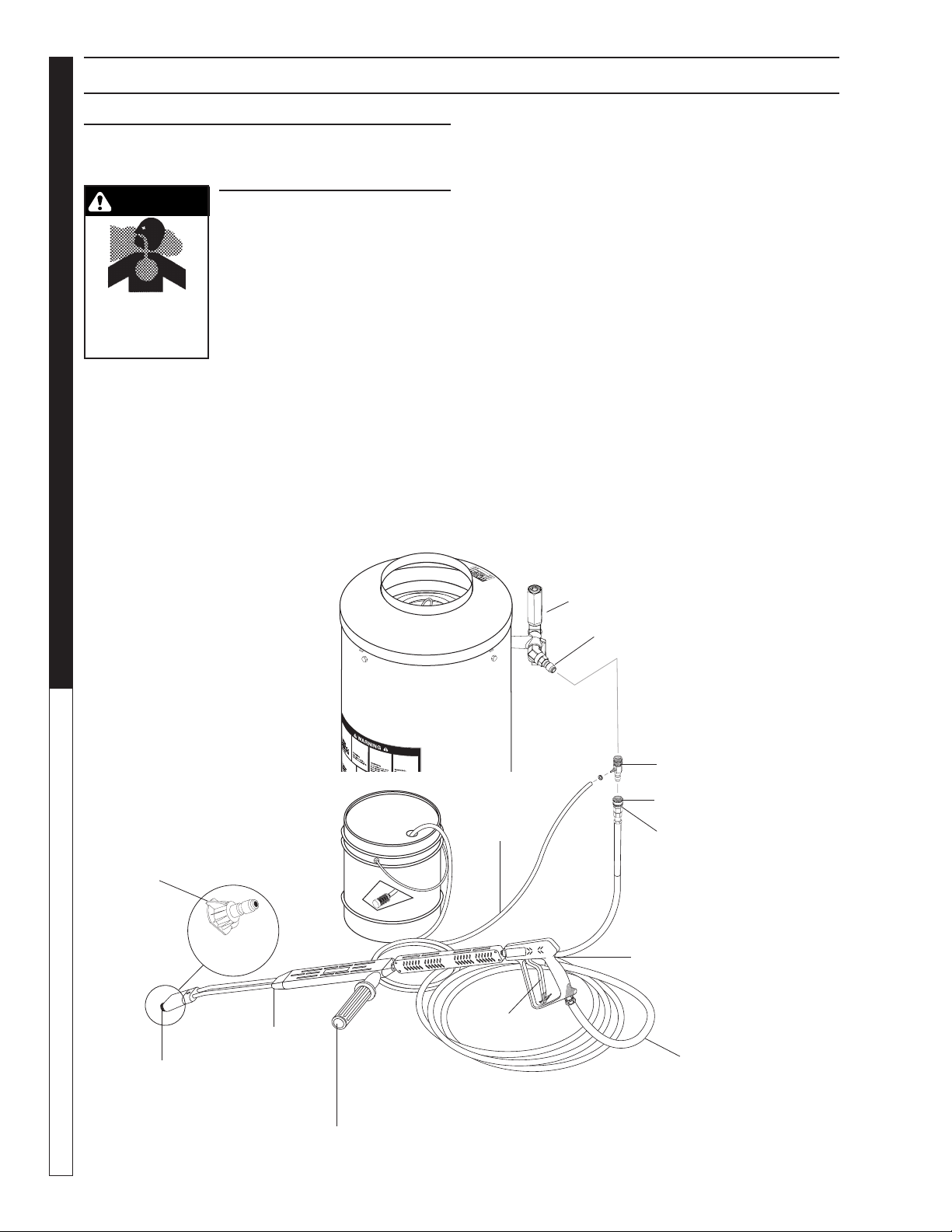
COMPONENT IDENTIFICATION
Discharge
Nipple
Wand Holder
Downstream
Detergent
Injector
(Kit Injector sold
separately)
Burner
Chamber
Pump
Burner Motor
Nozzle
Coupler
Variable Pressure
Insulated Wand
Control
Handle
High Pressure
Outlet Hose
Insulated
Spray Gun
Trigger
Detergent
Suction Hose
Detergent Bucket
(not included)
Garden Hose
(not included)
Fresh Water
Faucet
(not included)
Unloader
GFCI
Adjustable
Thermostat
ON - OFF
Switch
Nozzle
(Nozzles
Brass
(Black) sold
separately)
Hour Meter
CAUTION HOT WATER:
Must use insulated spray gun
and wand.
Manual Karcher STP 9.801-191.0 - D
7
PRESSURE WASHER
OPERATOR’S MANUAL
OPERATING INSTRUCTIONS
Electrical:
This machine, when installed, must be electrically
grounded in accordance to local codes. Check for
proper power supply using a volt meter.
Placement:
Do not locate near any combustible material. Keep all
flammable material at least 20 feet away.
Allow enough space for servicing the machine.
Local code will require certain distances from floor and
walls. (Two feet away from walls should be adequate.)
Water Source:
The water source for the pressure washer should be
supplied by a minimum 5/8" I.D. garden hose with a
city water pressure of not less than 30 PSI. If the water
supply is inadequate, or if the garden hose is kinked,
the attached pressure washer will run very rough and
the burner will not fire.
Connection:
Connect the wand, nozzle, hose and spray gun (where
applicable). On pipe thread connections, use teflon tape
to avoid water leaks. (See Component Identification).
Venting:
Adding exhaust vent pipe to your oil fired burner is not
recommended because restricted air flow causes car-
bon buildup, which affects the operation, and increases
maintenance on the coil. If a stack must be used, refrain
form using 90° bends. If the pipe can not go straight up
then use only 45° bends and go to the next size pipe.
The overall pipe length must not exceed 6 feet in length.
STARTING AND OPERATING
INSTRUCTIONS
To Start:
1. STOP! Read operator's man-
ual before operating. Failure
to read operation and warn-
ing instructions may result in
personal injury or property
damage.
2. Connect water supply hose
and turn on water.
3. Check fuel tank and pump oil
levels.
4. Connect high pressure hose to discharge nipple by
sliding quick coupler collar back. (If detergent is to
be applied, insert a detergent injector as shown in
Component Identification).
5. Insert quick coupler onto discharge nipple and
secure by pushing quick coupler collar forward.
6. Securely attach the desired high pressure nozzle
into wand coupler as described in steps 4 and 5.
7. Connect the power cord into the proper electrical
outlet, then push in the GFCI reset button (Refer
to serial plate for information.)
8. Grip spray gun handle securely and pull trigger.
Then turn variable pressure control handle coun-
terclockwise.
9. Turn switch to pump position. When a steady
stream of water flows from the spray gun and wand,
the machine is ready for cold water cleaning by turn-
ing the variable pressure control handle clockwise
to raise the pressure.
10. For hot water washing, turn the switch to the burner
position. (The burner will light automatically when
the trigger on the spray gun is pulled.)
To Stop:
1. If using the detergent injector, place the suction
line in a bucket of water allowing detergent to be
flushed from system.
2. Turn burner switch off and continue spraying water,
allowing the water to cool.
3. After water has cooled to less than 100°F, turn the
attached pressure washer off.
4. Turn garden hose water off. Open the spray gun to
relieve remaining pressure.
5. Protect from freezing.
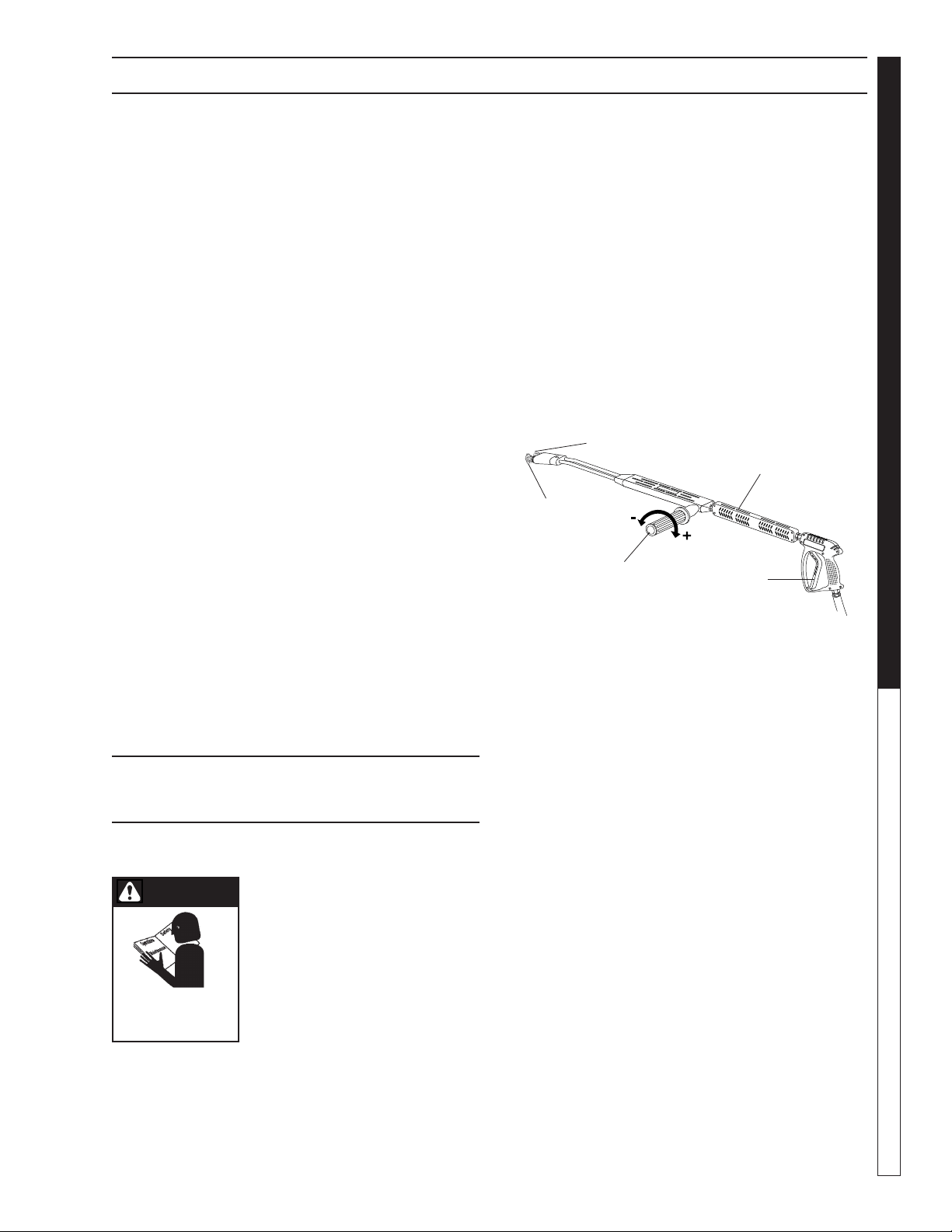
Selection of high or low pressure is accompanied by
turning the handle. Note: High pressure nozzle must
be inserted at end of wand to obtain high pressure. To
apply soap read operator's manual.
Variable Pressure
Control Handle
Trigger
Variable Pressure
Wand (VP)
High
Pressure
Nozzle
Brass Soap Nozzle
(Sold Separately)
READ OPERATOR’S
MANUAL THOROUGHLY
PRIOR TO USE.
CAUTION
CAUTION
Manual Karcher STP 9.801-191.0 - D
OPERATOR’S MANUAL
PRESSURE WASHER
8
OPERATING INSTRUCTIONS
HOW TO USE THE
DETERGENT INJECTOR
WARNING: Some detergents
may be harmful if inhaled or in-
gested causing severe nausea,
fainting or poisoning. The harm-
ful elements may cause property
damage or severe injury.
The machine can siphon and
mix detergents with the use of
Karcher's detergent injector kit.
1. Pull injector quick coupler collar back and secure on
discharge nipple. Injector valve body arrow should
point in direction of flow.
2. Connect high pressure hose to injector nipple se-
curing quick coupler.
3. Start machine as outlined in Operating Instructions.
4. Place detergent pick-up tube into container of
detergent solution.
5. Turn pressure control handle counterclockwise on
the variable pressure wand. This lowers the pres-
sure by directing the water flow through the soap
nozzle and allows the detergent injector to siphon
soap.
6. Open trigger spray gun. Water detergent ratio is
approximately 15 to 1.
7. When you finish washing, rinse by simply turning
the variable pressure wand control handle clock-
wise to increase pressure.
NOTE: The detergent injector will not siphon with
water flowing through the high pressure nozzle at
the end of the wand.
8. For clean up, place detergent pick-up tube into
container of clear water and follow steps 5 and 8
to prevent detergent deposits from damaging the
injector.
WARNING
SOME DETERGENTS
MAY BE HARMFUL
IF INHALED OR
INGESTED.
CHAUD!
Discharge Nipple
Detergent Injector
(Kit Sold Separately)
Collar
Variable Pressure
Control Handle
Quick Coupler
Trigger
Relief Valve
Brass Soap
Nozzle
(Sold
Separately)
Variable Pressure
Wand (VP)
High Pressure
Hose
Spray Gun
Nozzle Quick
Coupler
Detergent
Pickup Tube

Manual Karcher STP 9.801-191.0 - D
9
PRESSURE WASHER
OPERATOR’S MANUAL
PREVENTATIVE MAINTENANCE AND SERVICE
PREVENTATIVE MAINTENANCE
1. Use clean fuel - kerosene, No. 1 home hearing
fuel or diesel fuel. Clean or replace fuel filter every
100 hours of operation. Avoid water contaminated
fuel as it will seize up the fuel pump. De-soot coils
monthly. Use an additive if diesel is being used.
2. Check to see that the attached pressure washer
water pump is properly lubricated.
3. Follow Winterizing Procedures to prevent freeze
damage to pump coils.
4. Always neutralize and flush detergent from system
after use.
5. If water is known to be high in mineral content, use
a water softener in your water system or de-scale
as needed.
6. Do not allow acidic, caustic or abrasive fluids to be
pumped through system.
7. Always use high grade quality cleaning products.
8. Never run pump dry for extended periods of time.
9. If machine is operated with smoking or eye burning
exhaust, coils will soot up, not letting water reach
maximum operating temperature. (See section on
Air Adjustments.)
10. Never allow water to be sprayed on or near engine
or burner assembly or any electrical component.
11. Periodically delime coils per instructions.
It is advisable, periodically, to visually inspect the
burner. Check air inlet to make sure it is not clogged
or blocked. Wipe off any oil spills and keep this equip-
ment clean and dry.
The areas around the pressure washer should be kept
clean and free of combustible materials, gasoline and
other flammable vapors and liquids.
The flow of combustion and ventilating air to the burner
must not be blocked or obstructed in any manner.
MAINTENANCE AND SERVICE
Unloader Valves:
Unloader valves are preset and tested at the factory
before shipping. Occasional adjustment of the unloader
may be necessary to maintain correct pressure. Call
your local dealer for assistance.
Winterizing Procedure:
Damage due to freezing is not covered by warranty.
Adhere to the following cold weather procedures
whenever washer must be stored or operated outdoors
under freezing conditions. During winter months, when
temperatures drop below 32°F, protecting your ma-
chine against freezing is necessary. Store machine in
a heated room. If this is not possible then mix a 50/50
solution of anti-freeze/water into a 5 gallon bucket.
Place a short section of garden hose into bucket and
connect it to machine. Elevate bucket and turn pump on
to siphon anti-freeze through machine. If compressed
air is available, an air fitting can be screwed into the inlet
connector and, by injecting compressed air, all water will
be blown out of system.
High Limit Hot Water Thermostat:
For safety, each machine is equipped with a high limit
control switch. In the event that the temperature of the
water should exceed its operating temperature, the high
limit control will turn the burner off until the water cools.
Pumps:
Use only SAE 30W non-detergent oil. Change oil after
the first 50 hours of use. Thereafter, change the oil
every three months or at 500 hour intervals. Oil level
should be checked by using the dipstick found on top
of the pump or the red dot visible through the oil gauge
window. Oil should be maintained at that level.
Cleaning of Coils:
In alkaline water areas, lime deposits can accumulate
rapidly inside the coil pipes. This growth is increased by
the extreme heat build up in the coil. The best preven-
tion for liming conditions is to use high quality cleaning
detergents. In areas where alkaline water is an extreme
problem, periodic use of Deliming Powder (part #9.804-
059.0) will remove lime and other deposits before coil
becomes plugged. (See Deliming Instructions for use
of Deliming Powder.)
Deliming Coils:
Periodic flushing of coils is recommended.
1. Fill a container or optional float tank with 4 gallons
of water, then add 1 lb. of deliming powder. Mix
thoroughly.
2. Remove wand assembly from spray gun and put
spray gun into container. Secure the trigger on the
spray gun into the open position.
3. Attach a short section (3-5 ft.) of garden hose to
machine to siphon solution from an elevated con-
tainer. Turn pump switch on, allowing solution to
be pumped through coils back into the container.
Solution should be allowed to circulate 2-4 hours.
4. After circulating solution flush entire system with
fresh water. Reinstall wand assembly to spray gun.
Removal of Soot in Heating Coil:
In the heating process, fuel residue in the form of soot
deposits may develop between the heating coil pipe
and block air flow which will affect burner combustion.
When soot has been detected on visual observation,
Athe soot on the coil must be washed off after coil has
been removed using the following steps:
Manual Karcher STP 9.801-191.0 - D
OPERATOR’S MANUAL
PRESSURE WASHER
10
PREVENTATIVE MAINTENANCE AND SERVICE
1. Remove the tank head assembly by lifting the tank
head off.
2. Remove the two pipe nipples and associated fit-
tings.
3. Lift the coil out of the outer wrap.
CAUTION: the coil weighs about 80 lbs. Use proper
lifting techniques.
4. Clean, repair and replace the coil by reversing the
above steps.
Coil Reinstallation
Reinstall by reversing the above steps 4 through 1.
Fuel:
Use clean fuel oil that is not contaminated with water
and debris. Replace fuel filter and drain tank every 100
hours of operation. Use Kerosene No. 1 or No. 2 Heating
Fuel (ASTM D306) or diesel only. NEVER use gasoline
in your burner tank. Gasoline is more combustible than
fuel oil and could result in a serious explosion. NEVER
use crankcase or waste oil in your burner. Fuel unit
malfunction could result from contamination.
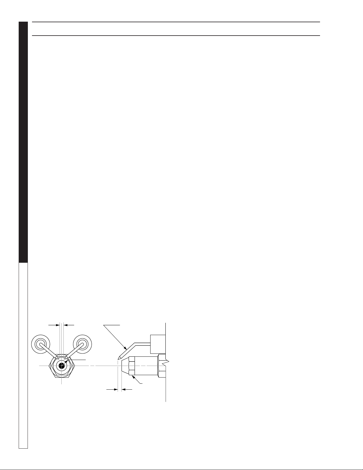
Ignition Circuit:
Periodically inspect wires, spring contact and elec-
trodes for condition, security and proper spacing. For
transformer test (CAUTION 10,000 VOLTS) use defect
free insulated screwdriver and keep fingers off blade!
Lay blade across one contact: OK if arc will span 1/2"
between end of blade and other contact (see following
illustration).
Electrode Setting: Beckett
Burner Nozzle:
Keep the tip free of surface deposits by wiping it with a
clean, solvent-saturated cloth, being careful not to plug
or enlarge the nozzle. For maximum efficiency, replace
the nozzle each season.
Fuel Control System:
The pressure washer utilizes a fuel solenoid valve
located on the fuel pump to control flow of fuel to the
combustion chamber. This solenoid is activated by a
pressure switch located on the unloader valve. When
an operator releases the trigger on the spray gun, the
pressure drops, allowing the pressure switch to activate
the fuel solenoid. The solenoid then closes, shutting off
the supply of fuel to the combustion chamber. Controlling
the flow of fuel in this way gives an instantaneous burn
or no burn situation, thereby eliminating high and low
water temperatures, and combustion smoke normally
associated with machines incorporating a spray gun.
Periodic inspection is recommended to insure that the
fuel solenoid valve functions properly. This can be done
by operating the machine and checking to see that when
the trigger on the spray gun is in the off position, the
burner is not firing.
Fuel Pressure Adjustment:
To adjust fuel pressure, turn the adjusting screw with a
screwdriver (located on the fuel pump) clockwise to
increase, counterclockwise to decrease. Do not exceed
200 PSI.
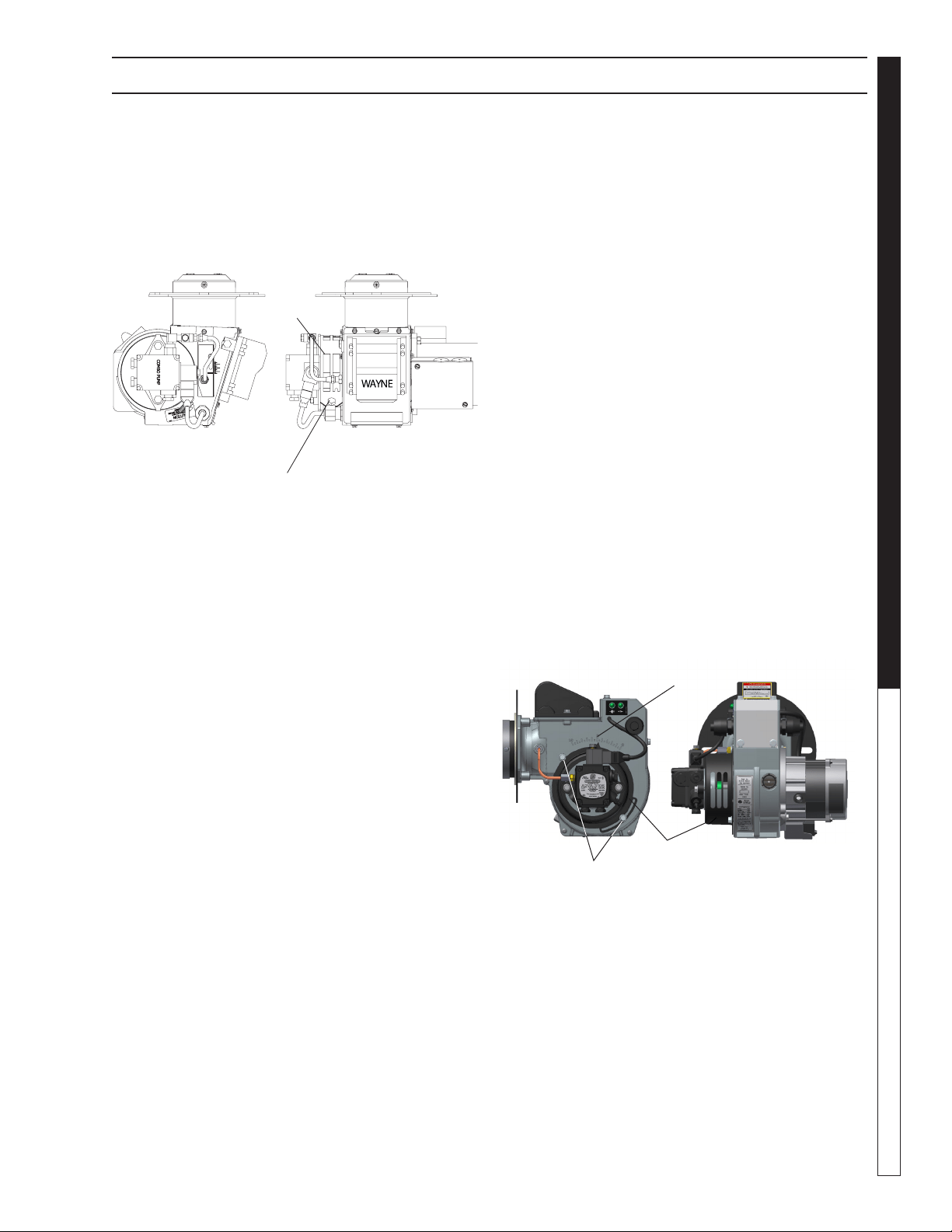
Wayne Burner Air Adjustment
Machines are preset and performance tested at the
factory — elevation 100' above sea level. A one time
correction for your location will pay off in economy,
performance and extended service life. If a smoky or
eye-burning exhaust is being emitted from the stack,
two things should be checked.
First, check the fuel to be certain that kerosene or No.
1 home heating fuel is being used.
Next, check the air adjustment on the burner. An oily,
black, smoky fire indicates a lack of air and the air band
should be moved to allow the air to flow through the
burner. Sharp, eye-burning fumes indicate too much
air flowing through the combustion chamber. The air
band should be moved to allow less air to flow through
the burner.
To adjust: Start the machine and turn burner ON.
Loosen the locking screws found in the air band open-
ings (refer to illustration) and close air band until black
smoke appears from burner exhaust vent. Next slowly
open the air band until white smoke just starts to appear.
Turn air band halfway back to the black smoke position
previously noted. Tighten the locking screws.
Side View
Top View
Nozzle
Electrode
1/8" min
5/32" max Gap
1/4" Above
nozzle center
1/8" AC- 3/16"
DC nozzle-to-tip
spacing
Manual Karcher STP 9.801-191.0 - D
11
PRESSURE WASHER
OPERATOR’S MANUAL
PREVENTATIVE MAINTENANCE AND SERVICE
If the desired position cannot be obtained using only
the air shutter, lock the air shutter in as close a position
as can be obtained, then repeat the above procedure
on the air band setting.
CAUTION: If white smoke appears from burner
exhaust vent during start-up or operation, discon-
tinue use and readjust air bands.
Wayne Burner Fuel Pressure Adjustment:
To adjust fuel pressure, first install a pressure gage into
the port just after the pump fuel exit. Turn the adjust-
ing screw (located at the regulator port) clockwise to
increase, and counterclockwise to decrease. Do not
exceed 205 psi or lower the pressure below 130 PSI,
when checked at the post-pump pressure port.
The fuel pressure may need to be adjusted due to
altitude. For every 500 ft altitude above sea level, the
boiling point of water goes down 1 °F. At high altitude
environments, this boiling point change may require
the heat input to be lowered so the water input does
not turn to steam earlier than at the factory settings
and activate the pressure sensors and pressure relief
equipment when the unit is operated and much higher
altitudes from factory settings or local dealer site set-
tings. Check with your dealer before making local site
fuel pressure adjustments.
Also, as ambient temperature changes seasonally, the
fuel temperature in the feed tank and air temperature in-
let can impact fuel flow. In more extreme temperatures,
this local-site adjustment may also require different fuel
nozzles for fuel inlet temperatures that are at seasonal
extremes (higher or lower) in locations where the tem-
perature changes are beyond moderate temperatures
of between 40°F and 90°F. Colder temperatures will
Air Band
Locking Screw
Air Band
make for a thicker flow and less fine a fuel spray while
hotter temperatures will make for a thinner flow a more
fine spray with the same nozzle. Consider alternate
nozzle configurations from the baseline factory-supplied
nozzle for operating in such temperature extremes if
performance is not meeting needs with air band and
fuel pressure settings alone.
NOTE: When changing fuel pump, a by-pass plug must
be installed in return line port or fuel pump will not prime.
KNA Clear Flame Oil Burner
Burner Air Adjustment: The oil burner on this machine
is preset for operation at altitudes below 1000 feet. If
operated at higher altitudes, it may be necessary to
adjust the air band for a #1 or #2 smoke spot on the
Bacharach scale.
To adjust, start machine and turn burner ON. Loosen
two locking screws found on the air band and close air
band until black smoke appears from burner exhaust
vent. Note air band position. Next, slowly open the air
band until white smoke just starts to appear. Turn air
band halfway back to the previously noted position.
Tighten locking screws.
Burner Air Adjustment
Reference Numbers
Air Band Locking Screws
Air Band
CAUTION: If white smoke appears from burner ex-
haust vent during start-up or operation, discontinue
use and readjust air bands.
NOTE: If a flue is installed, have a professional service-
man adjust your burner for a #1 or #2 smoke spot on
the Bacharach scale.
Manual Karcher STP 9.801-191.0 - D
OPERATOR’S MANUAL
PRESSURE WASHER
12
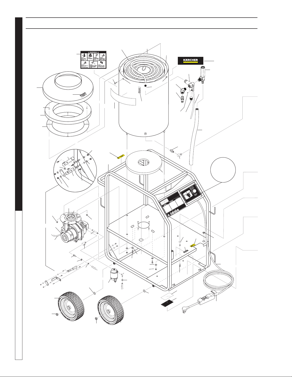
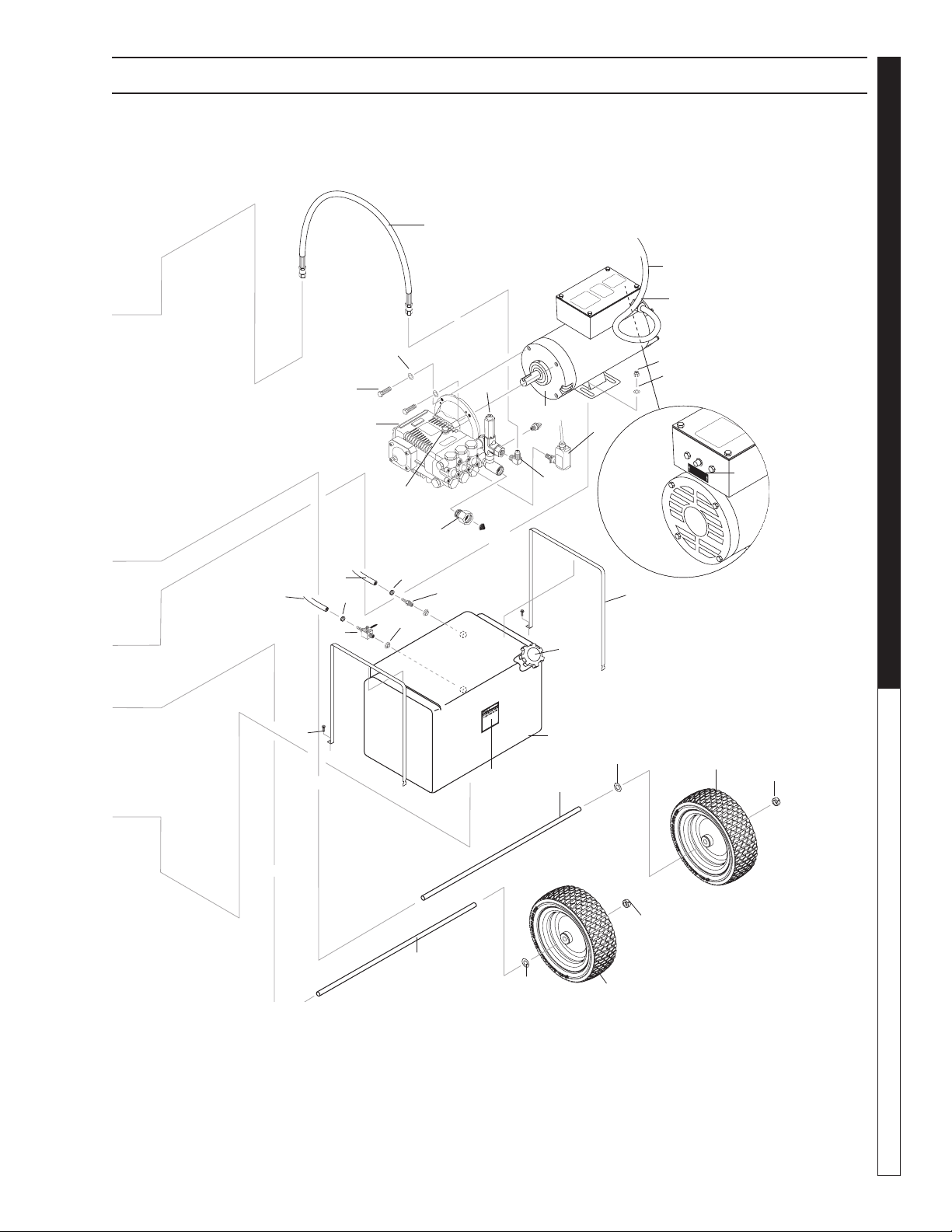
EXPLODED VIEW - LEFT
9.800-110.0
1
3
2
1
11
69
68
2
64
65
To
Fuel
Tank
70
73
76
71
75
74
55
52
38
37
44
36
39
44
35
41
60
43
46
50
51
47
48
49
67
53
66
63
62
64
26
90
16
89
To Fuel
Tank
88
10
(Reversed View
of Label)
(Reversed View
of Labels)
45
For
Detail See
Control
Panel
Illus.
56
78
82
83
80
79
81
84
85
25
3
83
83
82
59
58
57
14
31
54
42
42
87
Manual Karcher STP 9.801-191.0 - D
13
PRESSURE WASHER
OPERATOR’S MANUAL
EXPLODED VIEW - RIGHT
MOTOR O
VERLOAD
PUSH
TO
RE
SET
DEP
OSITIV
O DE REPOS
ICION
Enlarged
View
Overload
Button
77
33
21
20
30
15
87
17
23
25
26
28
27
24
72
12
88
8
13
88
9
7
6
5
34
4
3
2
1
4
3
2
1
22
61

Manual Karcher STP 9.801-191.0 - D
OPERATOR’S MANUAL
PRESSURE WASHER
14
EXPLODED VIEWS PARTS LIST
ITEM PART NO. DESCRIPTION QTY
1 9.802-782.0 Collar, 5/8" Bore Shaft 4
2 8.758-460.0 Wheel 12 In. Rim Steel 4
3 9.802-810.0 Washer, 5/8", Flat, SAE 4
4 8.922-672.0 Axle Long 2
5 9.802-081.0 Tank, Fuel 6 Gallon Blank 1
6 9.802-089.0 Cap, Fuel Tank,
Plastic H60-AV 1
7 9.802-053.0 Bushing, Rubber, Nitrile 2
8 9.802-141.0 Hose Barb, 1/4" Barb x 3/8"
Barb, Double 1
9 9.802-177.0 Valve, 1/4" Shut-Off 1
10 9.802-138.0 Hose Barb,
1/4" Barb x 1/4" ML Pipe 1
11 6.390-126.0 Clamp, Hose, UNI .46 - .54 4
12 9.802-254.0 Hose, 1/4" Push-On,
Fuel Line 11"
13 9.802-254.0 Hose, 1/4" Push-On,
Fuel Line 7"
14 9.800-018.0 Label, Tipover Hazard 1
15 9.802-146.0 Swivel, 1/2" MP x 3/4"
GHF w/Strainer 1
16 9.198-014.0 Washer 21/64 X 1" 4
17 9.802-039.0 Elbow, 1/2 JIC 3/8, 90°
(352007A) 1
9.802-042.0 Elbow 1/2" JIC, 3/8 Fem,
90DGR 1
18 9.804-025.0 Pump Protector, 1/4", 145° 1
20 9.802-720.0 Bolt, 3/8" x 1", NC HH 4
21 9.802-814.0 Washer, 3/8" Split Ring Lock,
Zinc 4
22 8.929-254.0 Pump KARCHER KFP2030S,
2.1 @3000 1725RPM
(231007D, 201507D) 1
8.923-808.0 Pump 3540F (352007A) 1
23 9.802-458.0 Switch, Pressure,
N/O, 1/4" NPT SS 1
24 9.804-516.0 Motor, 1.5 HP 120V
1725 RPM (231007D) 1
8.754-709.0 Motor, 2HP 1PH 115V
1750 RPM, 56C ODP 1
9.802-341.0 Motor, 5HP 1PH 230V
3450 RPM (352007A) 1
25 8.718-980.0 Washer, 5/16" Flat 8
26 9.802-776.0 Nut, 5/16" ESNA, NC 8
27 9.802-427.0 Cord, Service, SOWA, 3 ft.
12/3 (201507D)
9.802-436.0 Cord, Service, SEO, 2.67 ft.
10/3 (231007D, 352007A)
28 8.752-969.0 Strain Relief,
Small (231007D, 201507D) 1
9.802-518.0 Strain Relief,
STRT Lq Tite (352007A) 1
ITEM PART NO. DESCRIPTION QTY
30 8.754-696.0 Unloader, VBT Banjo
1/2M 3/8M, 3000PSI 1
9.175-018.0 UU1 3500PSI,Universal
Unloader (352007A) 1
31 9.800-049.0 Label, Manufacturer's
Cleaning Solution 1
33 8.918-425.0 Hose, 3/8" x 29", 2 Wire,
Pressure Loop 1
34 9.800-002.0 Label, Use Only Kerosene 1
35 9.149-003.0 Manifould Coil
Outlet Dicharge 1
36 8.902-433.0 Valve Safety, Relief 1
37 9.196-012.0 Plug 10-24UNF x 1/4 1
38 8.711-785.0 Hose, 3/8" Push-On 2.75 ft.
39 9.802-171.0 Nipple, 3/8" x 3/8" NPT
ST Male 1
41 9.800-021.0 Label, Hot Water Outlet 1
42 9.800-110.0 Label, Karcher, Logo
(Coil Tank) 2
43 8.919-733.0 Coil, Wrap, Outer, 1
Weldement
8.928-430.0 Assy, Outer Wrap STP, SS 1
(For models HDS 3.5/20 EA)
44 9.802-753.0 Screw, 1/4" x 3/4" HH NC,
Whiz Loc 8
45 9.802-793.0 Nut, Cage, 1/4" x 16 Gauge 4
46 8.925-217.0 Spare Coil Assy Vertical 1
Mini MTY
8.928-428.0 Assy, Coil, STP Mty 1
(For models HDS 3.5/20 EA)
47 9.800-041.0 Label, Warning, Text 1
48 9.800-006.0 Label, Hot/Caliete
w/Arrows Warning 1
49 8.719-913.0 Top Hat, Coil 1
50 9.802-904.0 Insulation, Tank Head,
16" OD x 8" ID 1
51 9.802-825.0 Clip, Retaining U-Type 4
52 9.802-042.0 Elbow, 1/2" JIC x 3/8"
Fem, 90° 1
53 8.706-827.0 Elbow, 1/4" Street, 1
Brass
54 9.803-108.0 Retainer Ring, Insulation 1
55 9.802-900.0 Insulation, Tank Bottom,
1" Blanket 1
56 9.803-120.0 Assembly, Frame, Black 1
8.922-545.0 Assembly, Frame 1
(133.0 & 134.0)
57 8.705-974.0 Nipple, 3/8" x 3/8" Hex 1
58 8.750-094.0 Thermostat, 150C/302F 1
59 8.706-241.0 Plug, 3/8, SQ head 1
60 9.802-041.0 Elbow, 3/8", Steel,
Street, 45° 1

Manual Karcher STP 9.801-191.0 - D
15
PRESSURE WASHER
OPERATOR’S MANUAL
EXPLODED VIEWS PARTS LIST
ITEM PART NO. DESCRIPTION QTY
61 9.802-753.0 Screw, 1/4-20 x 3/4" 2
62 8.756-181.0 Burner, MSR 3.75 120V 1
1T 120V S
8.756-709.0 Burner, MSR, 230V 1
1T 230V S (For models
STP-352007A)
63 8.756-861.0 Fuel nozzle, 1.10 X 80 BZ 1
8.754-953.0 Fuel Nozzle, 1.75 X 90AZ
(For models STP-352007A) 1
64 9.802-781.0 Nut, 3/8" Flange,
Whiz Loc, NC 4
65 9.802-424.0 Cord, Service, SEO, 16/4,
Coleman 64"
66 9.802-519.0 Strain Relief, 1/2" Metal,
Two Screw 1
67 9.803-264.0 Nipple, 1/4" x 3",
Black Pipe 1
68 8.725-306.0 Filter, Parker Fuel/Oil/H2O
(10 Micron), Generic 1
69 8.706-958.0 Hose Barb,
1/4" Barb x 1/4" Pipe, 90° 1
70 9.800-020.0 Label, Cold Water Inlet 1
71 9.800-014.0 Label, Intended for Outdoor
Use 1
72 9.800-032.0 Label, Motor Overload Reset,
Lexan 1
73 9.802-103.0 Bushing, Snap 1
74 9.802-432.0 GFCI, 120V 15A,
w/36' 12-3 Cord (231007D) 1
9.802-431.0 GFCI, 120V 20A,
w/36' 12-3 Cord (201507D) 1
9.802-430.0 GFCI, 240V 1PH 30A,
w/36' 10-3 Cord (352007A) 1
75 8.932-969.0 Label, Warning,
Service Cord 1
76 9.800-034.0 Label, Clear Lexan,
2-1/4" x 4-1/2" 1
77 9.803-092.0 Fuel Strap Long 2
8.922-616.0 Fuel Strap Long 2
(133.0, 134.0)
78 9.803-111.0 Lever, Brake 1
8.922-518.0 Lever, Brake (133.0, 134.0) 1
79 9.802-996.0 Bracket, Brake Pad 1
8.922-519.0 Bracket, Brake Pad Green 1
(133.0, 134.0)
80 9.802-997.0 Linkage, Brake 1
8.922-520.0 Linkage, Brake (133.0, 134.0) 1
81 9.802-705.0 Bolt, Carriage 4
82 9.802-773.0 Nut, 1/4" ESNA 4
83 9.802-802.0 Washer, 1/4" 12
ITEM PART NO. DESCRIPTION QTY
84 9.802-908.0 Insulation, Blanket, 18" x 52", 1
Fiberglass
8.756-907.0 Insulation, Blanket, 1
19.5 X 52, Fiberglass
(For models HDS 3.5/20 EA)
85 9.802-709.0 Bolt, 5/16" x 3/4" NC 4
86 9.802-047.0 Adapter, 1/2" x 1/2" Pipe 1
87 8.754-911.0 Check Valve,1 Way, 1/4"Barb 1
88 8.750-933.0 Band Hose Clamp, Hose 3
ID 1/8" - 5/16"
89 9.802-819.0 Washer, 7/16" x 2 1/2",
Zinc, PG Foot 3
90 9.802-710.0 Screw 5/16" x 1" NC 3
Manual Karcher STP 9.801-191.0 - D
OPERATOR’S MANUAL
PRESSURE WASHER
16
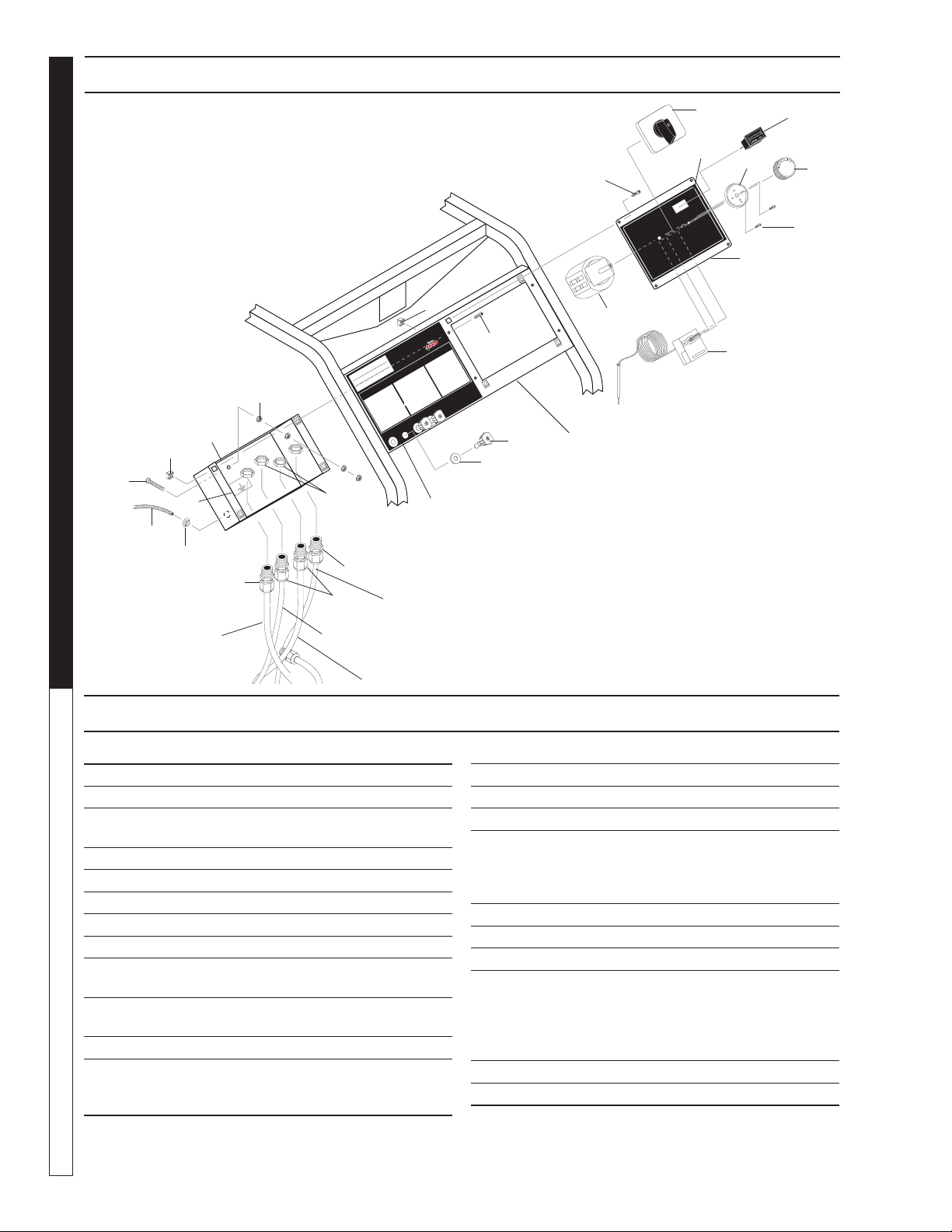
CONTROL PANEL EXPLODED VIEW
THERMOSTAT
TERMOSTATO
THERMOSTAT
PUMP
OFF
BURNER
GROUND
OPERATING
INSTRUCTIONS
INSTRUCCIONES
DE OPERACION
MODE D' EMPLOI
0°
RED
15°
YELLOW
25°
GREEN
40°
WHITE
17
7
10
18
14
15
19
12
13
12
13
To
Pressure
Switch
9
8
20
5
7
16
1
2
3
5
4
2
To
Thermostat
21
To Motor
To Power
Source
To Burner
Motor
CONTROL PANEL EXPLODED VIEW PARTS LIST
22
22
6
ITEM PART NO. DESCRIPTION QTY
1 8.750-094.0 Thermostat, 150C/302F 1
2 9.802-449.0 Switch, 3 PS, 120V-230V, 1Ph 1
3 9.804-519.0 Cover, Electric Box, Black 1
8.922-552.0 Cover, Elec Box (133.0, 134.0) 1
4 9.804-520.0 Label, Electric Box 1
5 9.802-7590 Screw, 10/32" x 1/2" BHSOC Blk 8
6 8.718-779.0 Screw, 4mm x 6mm 4
7 9.802-791.0 Nut, Cage, 10/32" x 16 Ga 8
8 See Page 17 Nozzle 4
9 9.802-064.0 Grommet, Rubber,
Nozzle Holder 4
10 9.804-521.0 Box, Electric, black 1
8.922-551.0 Box, Electric (133.0, 134.0) 1
11 8.712-190.0 Bezel, Plastic Thermostat 1
12 8.752-969.0 Strain Relief, Strt,
Lq, Tite Small (231007D,
201507D, 352007A) 2
ITEM PART NO. DESCRIPTION QTY
13 9.802-514.0 Strain Relief, Strt, Lq, Tite 2
14 9.802-447.0 Conduit, Corr, Tubing, 1/4" 2 ft.
15 9.802-103.0 Bushing, Snap, 5/8" 1
16 9.804-526.0 Label, Karcher 1
STP Control Panel
8.753-780.0 Label Control Panel 1
(133.0, 134.0)
17 9.802-695.0 Nut, 10/32" Keps 4
18 9.802-762.0 Screw, 10/32" x 1-1/4" 1
19 9.800-040.0 Label, Ground 1
20 9.804-524.0 Panel, Control, Black 1
8.922-550.0 Panel, Control (133.0, 134.0) 1
9.802-754.0 ▲ Screw, 1/4" x 1/2" HH,
NC, Whiz Loc 4
9.802-775.0 ▲ Nut, 1/4" Flange 4
21 9.802-283.0 Hour Meter 1
22 8.750-096.0 Knob Thermostat 1
▲ Not Shown
Manual Karcher STP 9.801-191.0 - D
17
PRESSURE WASHER
OPERATOR’S MANUAL
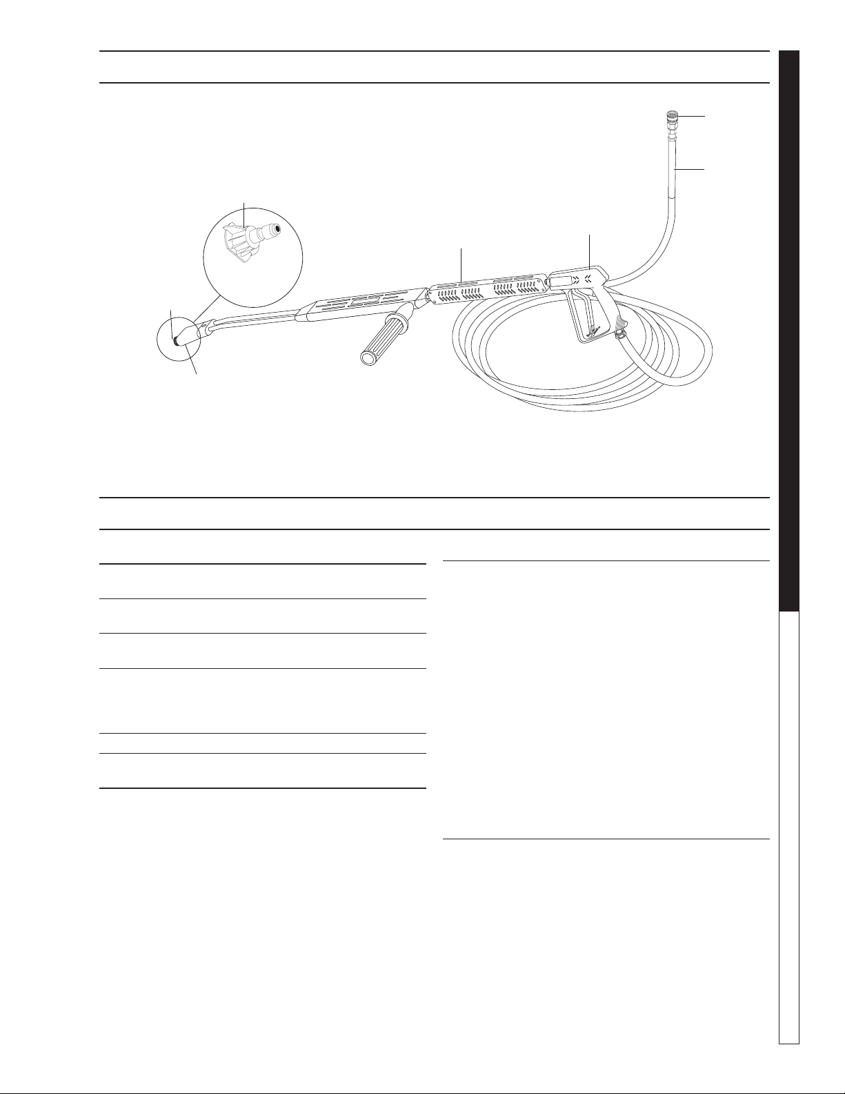
HOSE AND SPRAY GUN EXPLODED VIEW
1
2
3
4
7
6
5
HOSE AND SPRAY GUN PARTS LIST
ITEM PART NO. DESCRIPTION QTY
1 9.802-166.0 Coupler, 3/8" Female 1
9.802-100.0 ▲ Quick Coupler O-Ring LG 1
2 8.925-130.0 Hose, 3/8" X 50' 1W 1
4000PSI SW/SO/CPL
3 8.710-384.0 Gun, St-1500, 5000 PSI, 1
10.4 Gpm
4 9.802-222.0 Wand, VP Zinc 1/4" 1
w/Coupler, w/Soap Nozzle
9.803-267.0 ▲ AL Wand Repair Kit, 1
Stainless Seat
5 9.802-286.0 Brass Soap Nozzle Only, 1/8" 1
6 9.802-165.0 Coupler, 1/4" Male 1
9.802-096.0 Quick Coupler O-Ring Sm 1
ITEM PART NO. DESCRIPTION QTY
7 9.802-288.0 Nozzle, SAQMEG 1503, 1
Yellow (201507D)
9.802-289.0 Nozzle SAQMEG 2503, 1
Green (201507D)
9.802-290.0 Nozzle, SAQMEG 4003, 1
White (201507D)
8.712-338.0 Nozzle, SAQMEG 1503.5, 1
Yellow (231007D)
8.712-339.0 Nozzle, SAQMEG 2503.5, 1
Green (231007D)
8.712-340.0 Nozzle, SAQMEG 4003.5, 1
White (231007D)
9.802-300.0 Nozzle, SAQMEG 1505 1
Yellow (352007A)
9.802-301.0 Nozzle, SAQMEG 2505, 1
Green (352007A)
9.802-302.0 Nozzle, SAQMEG 4005, 1
White (352007A)
▲ Not Shown
Manual Karcher STP 9.801-191.0 - D
OPERATOR’S MANUAL
PRESSURE WASHER
18
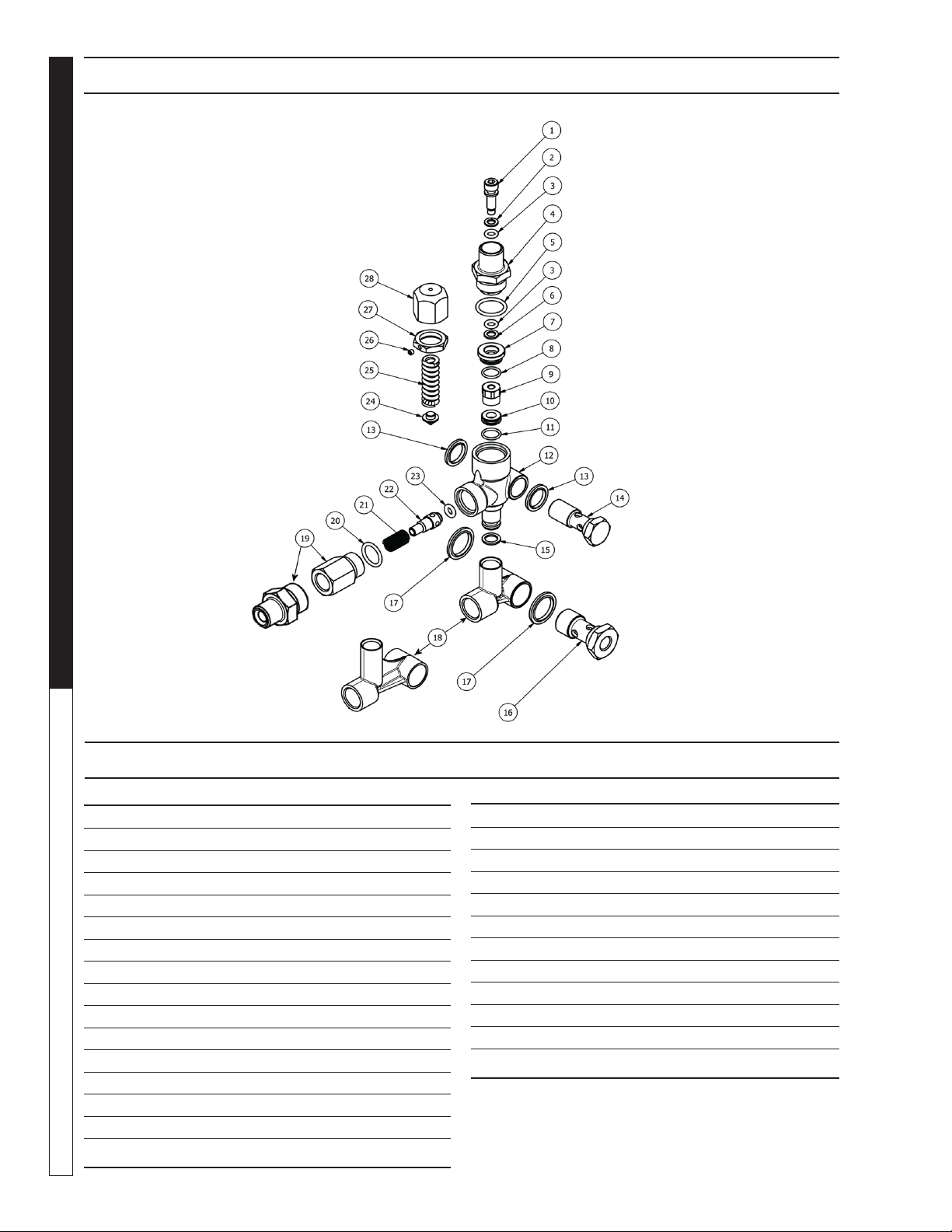
VBT UNLOADER EXPLODED VIEW
VBT UNLOADER EXPLODED VIEW PARTS LIST
ITEM PART # DESCRIPTION KIT QTY
1* 8.754-929.0 Stem C 1
2* 9.803-912.0 Backup Ring A 1
3* 8.754-930.0 O-ring, Ø2.62 x 6.02 A 2
4 8.730-882.0 Stem Connector 1
5* 9.803-193.0 O-ring, Ø2.62 x 20.24 A 1
6* 9.803-908.0 Backup Ring A 1
7 9.803-907.0 Guide Bushing 1
8* 9.803-906.0 O-ring, Ø1.78 x 14 A 1
9* 8.754-959.0 Ball SubAssembly C 1
10* 8.754-933.0 Seat C 1
11* 8.754-934.0 O-ring, Ø1.78 x 12.42 A,C 1
12 8.754-935.0 Valve Body 1
13 9.802-893.0 Seal Washer 3/8 1
14 9.803-919.0 Banjo Bolt 3/8 1
15* 8.754-936.0 O-ring, Ø2.62 x 10.78 A 1
16 9.803-920.0 Banjo Bolt, 1/2, w/1/4" Port 1
ITEM PART # DESCRIPTION KIT QTY
17 9.803-914.0 Seal Washer 1/2) 1
18 8.754-937.0 Bypass Manifold 1
19 9.802-892.0 Outlet Connector 3/8 MPT 1
20* 9.803-191.0 O-ring, Ø2.62 X 17.13 A,B 1
21* 8.933-017.0 Poppet Spring B 1
22* 8.754-939.0 Poppet B 1
23* 8.754-940.0 O-ring, Ø3 x 6 A,B 1
24* 8.754-961.0 Plate C 1
25* 8.933-018.0 Spring 1500-4000 PSI C 1
26 8.933-021.0 Set Screw 1
27 9.803-925.0 Nut 1
28 9.803-926.0 Knob, Brass, Unloader 1
* Included in Kit
Kit A 8.754-941.0 O-Ring Repair Kit
Kit B 8.754-942.0 Outlet Repair Kit
Kit C 8.754-957.0 Stem Repair Kit
8.754-696.0
UNLOADER, VBT BANJO 1/2M 3/8M, 3000PSI (SPARE)
Manual Karcher STP 9.801-191.0 - D
19
PRESSURE WASHER
OPERATOR’S MANUAL
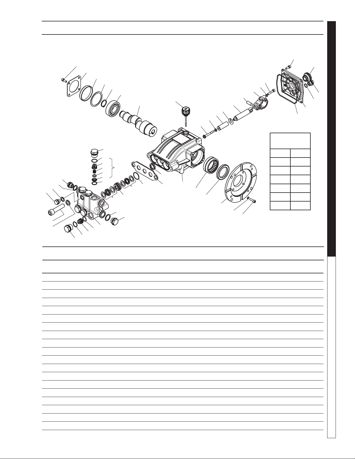
KFP SERIES PUMP EXPLODED VIEW
KFP SERIES PUMP PARTS LIST
8.929-254.0 KFP2030S
ITEM PART NO. DESCRIPTION QTY
1 8.754-841.0 Crankcase 1
2* See Kits BelowPlunger Oil Seal 1
3 8.758-216.0 Spacer 1
4* See Kits Below"O" Ring Ø1.78X26.7 3
5* See Kits BelowU Seal 3
6* See Kits BelowPressure Ring 3
7* See Kits BelowU-Seal 3
8 9.803-199.0 Washer, Copper G1/2 1
9 9.802-926.0 Plug, Brass G1/2 1
10 8.754-852.0 Manifold (16mm Models) 1
11* 8.717-233.0 "O" Ring Ø1.78x15.6 6
12* See Kits BelowValve Assembly 6
13* 9.803-948.0 "O" Ring Ø1.78x18.77 6
14 9.803-949.0 Valve Plug 6
15 8.754-850.0 Washer, Lock 2
16* 8.929-349.0 Bolt Manifold 16MM 2
17 8.754-851.0 Plug, Brass G1/4 (16mm) 1
18 8.754-845.0 Washer, Copper G1/4 (16 mm Models) 1
19 9.803-198.0 Washer, Copper G3/8 1
32
38*
39*
40*
41*
42
43
44
36
45
25
49
20
48
47
46
25
26
27
28
29
30
31
14
13*
24*
23*
22*
21*
11*
7*
8
9
6*
5*
4*
3
20
19
18
17
16*
15
14
13*
12*
11*
10
33
34
35
36
37
2*
1
12*
TORQUE
SPECS
Item # Ft.-lbs
14 66
16 66
25 8
37 8
38 9.5
45 12.5

Manual Karcher STP 9.801-191.0 - D
OPERATOR’S MANUAL
PRESSURE WASHER
20
KFP SERIES PUMP PARTS LIST
ITEM PART NO. DESCRIPTION QTY
20 8.707-262.0 Plug, Brass G3/8 2
21* See Kits Below Valve Seat 6
22* See Kits Below Valve Plate 6
23* See Kits Below Valve Spring 6
24* See Kits Below Valve Cage 6
25 9.802-939.0 Screw, Hex M6M 16mm 8
26 8.717-137.0 Bearing Cover 2
27 9.803-954.0 Bearing Seal 1
28 8.754-843.0 Seal Spacer, Crankshaft 1
29 9.802-914.0 Snap Ring, 25 mm 1
30 9.803-955.0 Bearing, Ball 1
31 8.754-836.0 Shaft, 5/8" Hollow 1
32 8.754-219.0 Oil Dipstick 1
33 8.754-840.0 Bearing Needle 1
34 8.754-826.0 Seal, Crankshaft 1
35 8.754-844.0 Flange, Motor 1
36 9.803-218.0 Washer 6mm 10
37 8.752-824.0 Screw, M6 x 20 4
38* 8.754-855.0 Bolt, Plunger 3
39* 8.754-092.0 Washer, Copper 3
40* 8.754-848.0 Plunger, 16mm 3
41* 9.803-962.0 Spacer, Copper 3
42 8.754-827.0 Plunger Rod 3
43 9.803-965.0 Connecting Rod Pin 3
44 9.803-966.0 Connecting Rod 3
45 8.933-020.0 Screw, Connecting Rod 6
46 8.754-847.0 O-ring Ø2.62 X 111.62 1
47 8.754-842.0 Cover, Crankcase 1
48 9.803-906.0 O-ring Ø1.78 X 14 1
49 9.803-202.0 Sight Glass, G3/4 1
* Available in kit (See below)
REPAIR KIT
NUMBER 8.754-856.0 8.929-348.0 8.754-858.0 8.754-859.0 9.803-937.0 8.759-015.0
KIT DESCRIPTION
Plunger
Seals
16 mm**
Seal Packing
16 mm**
Plunger
16 mm**
Complete
Valve Plunger Oil Seals
Plunger Seals
16mm**
ITEM NUMBERS
INCLUDED
4, 5, 7, 16 4, 5, 6, 7, 16 38, 39, 40, 41 11, 12, 13 2
4, 5, 7,16
NO. OF
CYLINDERS KIT
WILL SERVICE
3 1 1 6 3 1
Manual Karcher STP 9.801-191.0 - D
21
PRESSURE WASHER
OPERATOR’S MANUAL
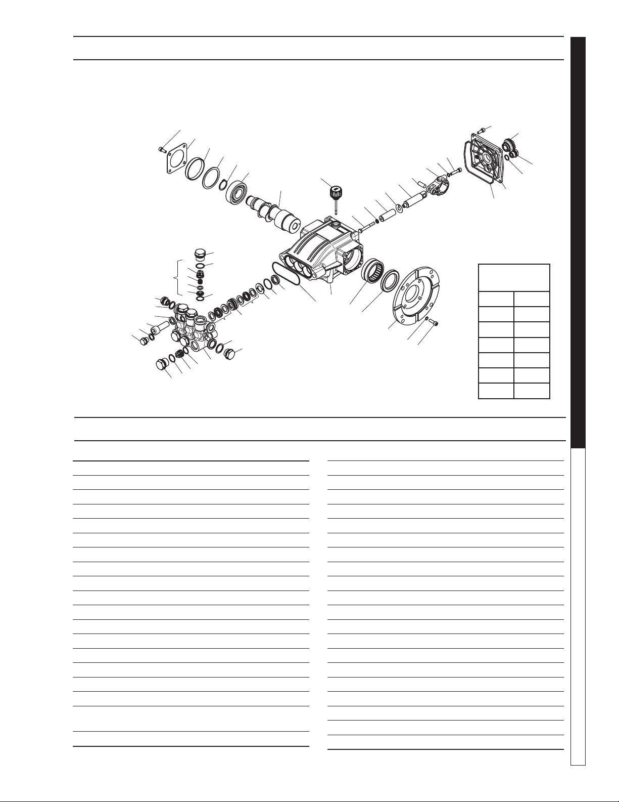
SF SERIES PUMP EXPLODED VIEW
SF SERIES PUMP EXPLODED VIEW PARTS LIST
13
6
8
1
3
9
10
11
12
13
14
15
21
20
17
16
12
14
15
22
23
24
25
26
27
28
31
32
33
35
39
40
41
42
43
45
44
37
46
47
48
26
2
5
7
18
19
29
30
34
36
38
49
4
37
50
21
ITEM PART NO. DESCRIPTION QTY
19 8.754-850.0 Washer, Lock 2
20 9.803-198.0 Washer, Copper G3/8 1
21 8.707-262.0 Plug, Brass G3/8 2
22* See Kits Below Valve Seat 6
23* See Kits Below Valve Plate 6
24* See Kits Below Valve Spring 6
25* See Kits Below Valve Cage 6
26 9.802-939.0 Screw, M6 X 16 8
27 8.717-137.0 Bearing Cover 1
28 9.803-954.0 Bearing Seal 1
29 8.754-843.0 Seal Spacer, Crankshaft 1
30 9.802-914.0 Snap Ring, 25 mm 1
31 9.803-955.0 Bearing, Ball 1
32 8.754-839.0 Shaft, 5/8" Hollow 1
33 8.754-219.0 Oil Dipstick 1
34 8.754-840.0 Bearing Needle 1
35 8.754-826.0 Seal, Crankshaft 1
36 8.754-844.0 Flange, Motor 1
37 9.803-210.0 Washer 10
38 8.752-824.0 Screw, 6 mm 4
ITEM PART NO. DESCRIPTION QTY
1 8.754-841.0 Crankcase 1
2 8.754-846.0 O-ring Ø1.78 X 72.75 1
3* See Kits Below Plunger Oil Seal 3
4* See Kits Below O-ring Ø1.78 X 26.7 3
5* See Kits Below Washer, Pressure Ring 3
6* See Kits Below U-Seal 3
7* See Kits Below Pressure Ring 3
8* See Kits Below U-Seal 3
9 9.803-199.0 Washer, Copper G1/2 1
10 9.802-926.0 Plug, Brass G1/2 1
11 8.754-852.0 Manifold (16mm Models) 1
8.754-853.0 Manifold (14mm Models) 1
12* 8.717-233.0 O-ring Ø1.78 X 15.6 6
13* See Kits Below Valve Assembly 6
14* 9.803-948.0 O-ring Ø1.78 X 18.77 6
15 9.803-949.0 Valve Plug 6
16 8.754-851.0 Plug, Brass G1/4 (16mm) 1
17 8.754-845.0 Washer, Copper G1/4
(16mm Models) 1
18 8.754-854.0 Bolt, Manifold M14 X 40 2
TORQUE
SPECS
Item # Ft.-lbs
15 65
18 55
26 8
38 10
39 10
46 10
8.923-808.0 SF3530F

Manual Karcher STP 9.801-191.0 - D
OPERATOR’S MANUAL
PRESSURE WASHER
22
SF SERIES PUMP EXPLODED VIEW PARTS LIST
ITEM PART NO. DESCRIPTION QTY
39* 8.754-855.0 Bolt, Plunger 3
40* 8.754-092.0 Spacer, Copper 3
41 8.754-849.0 Plunger, 14mm 3
42 9.803-962.0 Spacer, Copper 3
43 8.754-827.0 Plunger Rod 3
44 9.803-965.0 Connecting Rod Pin 3
45 9.803-966.0 Connecting Rod 3
46 8.933-020.0 Screw, Connecting Rod 6
47 8.754-847.0 O-ring Ø2.62 X 111.62 1
48 8.754-842.0 Cover, Crankcase 1
49 9.803-906.0 O-ring Ø1.78 X 14 1
50 9.803-202.0 Sight Glass, G3/4 1
REPAIR KIT
NUMBER 8.754-860.0 8.754-861.0 8.754-862.0 8.754-859.0 9.803-937.0
KIT DE-
SCRIPTION
Plunger
Seals
14 mm
Seal Packing
14 mm
Plunger
14 mm
Complete
Valve
Plunger Oil
Seals
ITEM
NUMBERS
INCLUDED
4, 6, 8 4, 5, 6, 7, 8 39, 40, 41, 42 12, 13, 14 3
NO. OF
CYLINDERS
KIT WILL
SERVICE
3
1 1 6 3
Manual Karcher STP 9.801-191.0 - D
23
PRESSURE WASHER
OPERATOR’S MANUAL
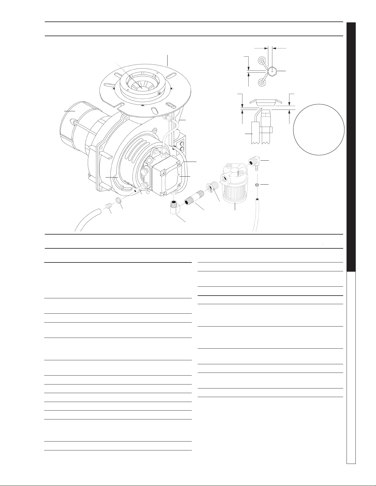
BURNER ASSEMBLY EXPLODED VIEW PARTS LIST
13
11
3
6
5
4
8
9
10
1
14
12
13
1/8"min
5/32" max Gap
1/8" AC
3/16" DC Nozzle-to-tip
spacing
1/4" Above
nozzle center
1-3/8"
BURNER ASSEMBLY EXPLODED VIEW
2
15
18
7
16
ITEM PART NO. DESCRIPTION QTY
1 8.756-181.0 Burner, MSR 3.75 120V 1
1T 120V S
8.756-709.0 Burner, MSR, 230V 1
1T 230V S (For models
STP-352007A)
2 8.706-941.0 Hose Barb, 1
1/4" Barb x 1/4" Mpt, Brass
3 8.706-827.0 Elbow, 1/4" Street 1
4 9.803-043.0 Nipple, Pipe 1/4" x 2" 1
Zinc Sch 80 Mpt
5 8.706-297.0 Bushing, 3/8" Steel Yellow 1
Chrome
6 8.709-153.0 Filter, Fuel Hotsy, 3/8" Fem 1
7 8.706-965.0 Hose Barb, 1
1/4" Barb x 3/8" ML Pipe, 9
8 8.700-759.0 Fuel Pump Suntec 120V 1
9 9.802-640.0 Fuel Solenoid 1
10 8.919-114.0 Ignitor, 120V Crossfire 1
11 8.750-778.0 Electrode Crossfire 1
12 9.802-655.0 Air Cone, F-6 1
13 8.756-861.0 Fuel nozzle, 1.10 X 80 BZ 1
8.754-953.0 Fuel Nozzle, 1.75 X 90AZ
(For models STP-352007A) 1
14 8.750-517.0 Motor, 120V Crossfire 1
ITEM PART NO. DESCRIPTION QTY
15 6.390-126.0 Clamp Hose, Uni .46-.54 1
16 8.750-933.0 Band Hose Clamp, Hose
Id 1/8" - 5/16" 1
17 8.754-911.0 Check Valve, 1 way, 1/4" 1
16 8.717-711.0 ▲ Screen, Fuel Filter 1
17 9.802-649.0 ▲ Blower Wheel 4.25 x 2.5 1
Beckett
8.750-520.0 ▲ Blower Wheel Crossfire 1
18 9.802-648.0 ▲ Coupling Assy 5/16" 1
Beckett
8.750-543.0 ▲ Coupling Crossfire 1
19 9.802-646.0 ▲ Valve Stem Kit 1
Cleancut Pump
20 9.802-666.0 ▲ Screen, Fuel Pump 1
21 9.802-514.0 ▲ Strain Relief, Lt, Str, 1
1/2 Npt, .23-.45 D
22 9.802-525.0 ▲ Locknut, 1/2" 1
▲ Not Shown
Cone distances
and electrode
gaps checked with
burner gage
(8.922-740.0), sold
separately.
Manual Karcher STP 9.801-191.0 - D
OPERATOR’S MANUAL
PRESSURE WASHER
24
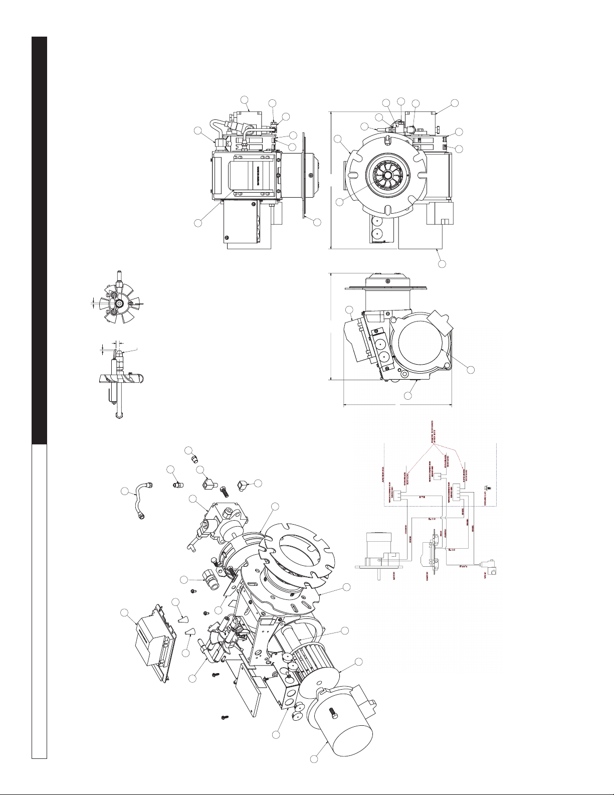
Replacement Parts
For best performance specify genuine WAYNE replacement parts
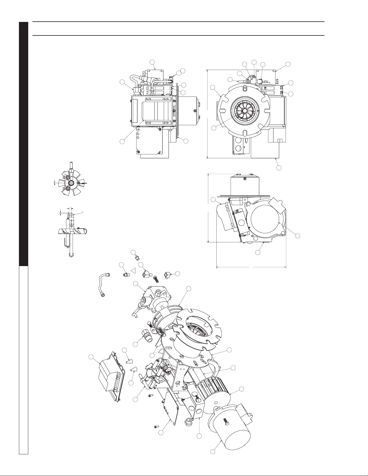
WAYNE BURNER EXPLODED VIEW
(.32)
(.12)
REF. NOZZLE
(.12)
ELECTRODE SETTINGS
ASSEMBLED VIEWS
(10.39)
(10.22)
(13.20)
2
25
1
25
7
8
34
31
22
24
10
1
1
34
31
24
7
8
212
30
23
EXPLODED VIEW
2
21
22
31
34
24
8
10
37
25
26
1
9
3
3
4
27
30
B

Manual Karcher STP 9.801-191.0 - D
25
PRESSURE WASHER
OPERATOR’S MANUAL
Replacement Parts
For best performance specify genuine WAYNE replacement parts
WAYNE BURNER PART LIST
ITEM PART NO. DESCRIPTION QTY
1 8.759-201.0 Tube/Hous-101392-001/ 5A/3.5"/3"I 1
2 8.759 -202.0 Ignitor- D W / M Plate 120V 1
3 8.759 -203.0 Spr ing, C ontac t 1
4 8.756-740.0 Junction Box, MSR, Black Body 1
7 8.700 -707.0 Air Band Inner "M" 1
8 8.700 -708.0 Band, Air Outer 8 -Hole Mod M 1
9 8.759-129.0 Plate Slot Cover 1
10 8.756-298.0 Gun Assembly, Burner-RG/ *CST/ *1 1/4"BB1 1
19 8.759-204.0 Decal, UL-Under 3 GPH Non C57 1
21 8.759-206.0 Strain Relief-Low Profile 1
22 8.756-284.0 Connector, Male-3/16" x 1/ 8"IPT 1
23 8.700 -704.0 Oil Line Assembly 6" 1
24 8.756-290.0 Pump - Combo /W Solenoid 120V 1
25 8.756-292.0 Motor 1/7 HP 120/60 1
26 8.700-822.0 Coupling "M" 1
27 8.700-726.0 Fan - 3.12" x 4.25"D 1/2" Bore 1
30 8.758-287.0 Fitting, Elbow 90* Street 1/ 8 1
31 8.758-285.0 Plug, Pipe HXHD 1/ 8" NPT 1
34 8.758-286.0 Tee, Street-1/ 8 X 1/ 8 Brass 1
35 8.759 -130.0 Stop per, # 4 C ork 1
36 8.700-692.0 Flange Gasket (2 Each) 2
37 8.756-739.0 Junction Box, MSR, Black Cover 1
Manual Karcher STP 9.801-191.0 - D
OPERATOR’S MANUAL
PRESSURE WASHER
26
ASSEMBLEDVIEWS
EXPLODED VIEW
(.32)
(.12)
REF. NOZZLE
(.12)
ELECTRODESETTINGS
(10.39)
(10.25)
(13.20)
2
21
22
31
34
24
8
10
25
26
1
9
3
3
2
25
1
25
7 8
34
31
22
24
10
1
1
34
31
24
7
8
21
2
23
4
27
30
30
23
WIRING DIAGRAM
Replacement Parts for STP-352007A and STP-352007A
For best performance specify genuine KNA replacement parts

Manual Karcher STP 9.801-191.0 - D
27
PRESSURE WASHER
OPERATOR’S MANUAL
Replacement Parts for STP-352007A and STP-352007A
For best performance specify genuine KNA replacement parts
ITEM PART NO. DESCRIPTION QTY
1 8.759-207.0 Tube/Hous-21922-001/6A/3.75"/.88"I 1
2 8.759-208.0 Ignitor-D W/M Plate 230V 1
3 8.759-203.0 Spring,Contact 2
4 8.756-740.0 J-Box,3X4 (No Knockouts) 1
7 8.700-707.0 Band, Air Inner-Mod M 1
8 8.717-826.0 Band, Air Outer 8-Hole Mod-M 1
9 8.759-130.0 Plate, Slot Cover 1
10 8.756-297.0 Gun-RG/*CST/*1 1/4"BB 1
21 8.759-206.0 Strain Relief-Low Profile 1
22 8.756-284.0 Connector, Male-3/16" X 1/8"IPT 1
23 8.700-704.0 Oil Line ASM.-6" 1
24 8.700-760.0 Pump-S A2VA3006-N753 220V Combo 1
25 8.717-828.0 Motor,1/7 220/230-50/60 PSC 1
26 8.700-822.0 Coupling-EG1/M "A" Pumps 1
27 8.700-728.0 FAN-3.44"W X 4.25"D M 1/2" BOR 1
30 8.758-287.0 Fitting,Elbow 90* Street 1/8 1
31 8.758-285.0 Plug, PIPE HXHD 1/8" NPT 1
34 8.758-286.0 Tee,Street-1/8 X 1/8 Brass 1
36 8.700-692.0 Gasket, Flange-STD Large 2

Manual Karcher STP 9.801-191.0 - D
PRESSURE WASHER Troubleshooting Guide
28
PROBLEM POSSIBLE CAUSE SOLUTION
LOW OPERATING
PRESSURE
Faulty pressure gauge Install new gauge.
Insufficient water supply Use larger garden hose; clean filter washer at water inlet.
Old, worn or incorrect spray nozzle Match nozzle number to machine and/or replace with new
nozzle.
Plumbing or hose leak Check plumbing system for leaks. Re-tape leaks with teflon
tape.
Faulty or mis-adjusted unloader valve
(where applicable)
Adjust unloader for proper pressure. Install repair kit when
needed.
Worn packing in pump Install new packing kit.
Fold or dirty inlet or discharge valves in pump Clean inlet or discharge valves.
Worn inlet or discharge valves Replace with valve kit.
DETERGENT NOT
DRAWING
Air leak Tighten all clamps. Check detergent lines for holes.
Valve in the injector head may be blocked, dirty,
or damaged
Clean or replace valve in injector.
Filler screen on detergent suction hose plugged
Clean or replace.
Dried up detergent plugging metering valve Disassemble and clean thoroughly.
High viscosity of detergent Dilute detergent to specifications.
Hole in detergent line(s). Repair hole.
Low detergent level Add detergent if needed.
Discharge water temperature above 180° F Lower discharge water temperature.
PUMP RUNNING
NORMALLY BUT
PRESSURE LOW
ON INSTALLATION
Pump sucking air Check water supply and possibility of air
Valves sticking Check and clean or replace if necessary.
Unloader valve seat faulty Check and replace if necessary
Nozzle incorrectly sized
Check and replace if necessary (see serial plate for proper size).
Worn piston packing Check and replace if necessary.
FLUCTUATING
PRESSURE
Valves worn Check and replace if necessary.
Blockage in valve Check and replace if necessary.
Pump sucking air Check water supply and air see page at joints in suction line.
Worn piston packing Check and replace if necessary.
PUMP NOISY
Air in suction line Check water supply and connections on suction line.
Broken or weak inlet or discharge valve springs Check and replace if necessary.
Excessive matter in valves Check and clean if necessary.
Worn bearings Check and replace if necessary.
LOW WATER
TEMPERATURE
Improper fuel or water in fuel Drain fuel tank and replace with proper fuel.
Low fuel pressure Increase fuel pressure.
Weak fuel pump Check fuel pump temperature. Replace pump if needed.
Fuel filter partially clogged Replace as needed.
Soot build up on coils Clean coils with soot remover.
Lime build up on coils Clean inside of coils using coil cleaner.
Improper burner nozzle Call technical service for proper size.
WATER
TEMPERATURE
TOO HOT
Incoming water to machine warm or hot Lower incoming water temperature.
Fuel pump pressure too high Lower fuel pressure.
Fuel pump defective Replace fuel pump.
Detergent line sucking air Tighten all clamps. Check detergent line for holes.
Defective high limit switch (thermostat) Replace.
Insufficient water supplied Check GPM to machine.
Restricted water flow Check nozzle for obstruction, proper size.
TROUBLESHOOTING

Manual Karcher STP 9.801-191.0 - D
29
PRESSURE WASHER
OPERATOR’S MANUAL
PREVENTATIVE MAINTENANCE
This pressure washer was produced with the best available materials and quality craftsmanship. However, you
as the owner have certain responsibilities for the correct care of the equipment. Attention to regular preventative
maintenance procedures will assist in preserving the performance of your equipment. Contact your local pres-
sure washer dealer for maintenance. Regular preventative maintenance will add many hours to the life of your
pressure washer. Perform maintenance more often under severe conditions.
MAINTENANCE SCHEDULE
Replace Fuel Lines Annually
Pump Oil
(Non foaming)
SAE 10W-40
Inspect Daily inspect the oil level
Change After first 50 hours, then every 500 hours or annually
Clean Burner Filter Monthly (more often if fuel quality is poor)
Remove Burner Soot Annually
Burner Adjustment/Cleaning Annually
Descale Coil Annually (more often if required)
Replace High Pressure Nozzle Every 6 months
Replace Quick Connects Annually
Clean Water Screen/Filter Weekly
Clean Float/Supply Tank Every 6 months
Replace HP Hose Annually if there is any sign of wear
Grease Motor Every 10,000 hours
Replace Burner Nozzle Annually
OIL CHANGE RECORD
Date Oil Changed
Month/Day/Year
Estimated Operating
Hours Since Last
Oil Change
Date Oil Changed
Month/Day/Year
Estimated Operating
Hours Since Last
Oil Change
MAINTENANCE SCHEDULE

Manual Karcher STP 9.801-191.0 - D
PRESSURE WASHER WARRANTY
LIMITED NEW PRODUCT
WARRANTY—COMMERCIAL
PRESSURE WASHERS
Phone: 888-805-9852
Fax: 800-248-8409
www.karchercommercial.com
WHAT THIS WARRANTY COVERS
All Kärcher commercial pressure washers are warranted by Kärcher to the original purchaser to be free from defects in materials and workmanship
under normal use, for the periods specified below. This Limited Warranty, subject to the exclusions shown below, is calculated from the date of the
original purchase, and applies to the original components only. Any parts replaced under this warranty will assume the remainder of the pressure
washer’s warranty period.
SEVEN YEAR PARTS AND ONE YEAR LABOR WARRANTY
Components manufactured by Kärcher, such as frames, handles, top and bottom wraps, float tanks, fuel tanks, and belt guards. Xpert Series cold water
pressure washer have a three-year frame warranty. Internal components on the oil-end of Kärcher Classic series, electric powered axial pumps have a 5 year
warranty. Period of warranty on gas-engine axial pumps shall be one year; Kärcher crankshaft pumps have a 7 year warranty on non-wear parts. Heating
coils have a five year warranty from date of original machine purchase; stainless steel coils have a 10 year warranty.
ONE YEAR PARTS AND ONE YEAR LABOR WARRANTY
All other components, excluding normal wear items as described below, will be warranted for one year on parts and labor. Parts and labor warranty on these
parts will be for one year regardless of the duration of the original component manufacturer’s part warranty.
WARRANTY PROVIDED BY OTHER MANUFACTURERS
Motors, generators, and engines, which are warranted by their respective manufacturers, are serviced through these manufacturers’ local authorized
service centers. Kärcher is not authorized and has no responsibility to provide warranty service for such components. Motors manufactured outside
of the United States will be warranted by Kärcher.
WHAT THIS WARRANTY DOES NOT COVER
This warranty does not cover the following items:
1. Normal wear items, such as nozzles, spray guns, discharge hoses, wands, quick couplers, seals, filters, gaskets, O-rings, packings, pistons, pump
valve assemblies, strainers, belts, brushes, rupture disks, fuses, pump protectors.
2. Any components or other devices incorporated into a Kärcher product that are not manufactured by Kärcher, including, but not limited to gasoline
engines, pumps, etc.
3. Defects caused by improper or negligent operation or installation, accident, abuse, misuse, neglect, unauthorized modifications, repair or maintenance
of the product by persons other than authorized representatives of Kärcher, including, but not limited to, the failure of the Customer to comply with
recommended product maintenance schedules.
4. Kärcher products that have been returned
by the original Customer and are ultimately re-sold by an Authorized Servicing Dealer or other sales or
service outlet to another purchaser.
5. Kärcher products that are sold by any distributor or retailer that is not an official authorized dealer or retailer of Kärcher products.
6. Defects caused by acts of nature and disaster including, but not limited to, floods, fires, wind, freezing, earthquakes, tornadoes, hurricanes and
lightning strikes.
7. Defects caused by water sediments, rust corrosion, thermal expansion, scale deposits or a contaminated water supply (such as water in the unit with
chloride content higher than that of 80 mg/liter or use of chemicals not approved or recommended by Kärcher).
8. Defects caused by improper voltage, voltage spikes or power transients in the electrical supply.
9. Devices or accessories not distributed or approved by Kärcher.
10. Any cost of labor arising from the removal and reinstallation of the alleged defective part by Customer.
11. Transportation of the product to an Authorized Servicing Dealer, field labor, replacement rental and any freight charges.
Any components, accessories or other devices provided with the product but not manufactured by Kärcher (such as engines, pumps, etc.) are subject to
war-
ranties and service through their respective manufacturers authorized service centers and according to the applicable terms and conditions of such manufac-
turers warranties. Such components or other devices not manufactured by Kärcher should be referred by the Customer to an authorized service center or their
respective manufacturers for repair or replacement.
.TCUDNOC RO MOTSUC ,WAL YB GNISIRA REHTEHW ,DNIK YNA FO SEITNARRAW REHTO LLA FO UEIL NI SI YTNARRAW GNIOGEROF EHT
KÄRCHER MAKES NO ADDITIONAL WARRANTIES, EITHER EXPRESSED OR IMPLIED, INCLUDING, WITHOUT LIMITATION, ANY EXPRESSED
OR IMPLIED WARRANTIES OF MERCHANTABILITY OR FITNESS OF EQUIPMENT FOR A PARTICULAR PURPOSE AND ANY SUCH WARRAN-
TIES ARE EXPRESSLY DISCLAIMED. KÄRCHER FURTHER DISCLAIMS ANY WARRANTY THAT THE PRODUCT PURCHASED BY CUSTOMER
WILL MEET ANY PARTICULAR REQUIREMENT OF CUSTOMER EVEN IF KÄRCHER HAS BEEN ADVISED OF SUCH REQUIREMENT.
THE RIGHTS AND REMEDIES PROVIDED UNDER THIS WARRANTY ARE EXCLUSIVE AND IN LIEU OF ANY OTHER RIGHTS OR REMEDIES OF
CUSTOMER. KÄRCHER SHALL NOT UNDER ANY CIRCUMSTANCES BE
LIABLE TO ANY PERSON OR ENTITY INCLUDING, BUT NOT LIMITED
TO, THE CUSTOMER OR ANY END USER OF THE PRODUCT FOR ANY SPECIAL, INDIRECT, INCIDENTAL OR CONSEQUENTIAL DAMAGES
OR ECONOMIC LOSS, LOSS OF PROFITS OR LOSS OF USE OF THE PRODUCT, ARISING IN CONNECTION WITH THE SALE, DELIVERY,
INSTALLATION, TRAINING OR USE OF PRODUCT.
KÄRCHER’S LIABILITY, WHETHER IN CONTRACT OR IN TORT, ARISING OUT OF ANY WARRANTIES OR REPRESENTATIONS,
INSTRUCTIONS OR DEFECTS FROM ANY CAUSE, SHALL BE LIMITED EXCLUSIVELY TO THE COST OF REPAIR OR REPLACEMENT PARTS
UNDER AFORESAID CONDITIONS.
The purpose of the foregoing limitations on liability and Customer remedies is to protect Kärcher from unknown or undeterminable risks. Some states do
not allow the exclusion or limitation of incidental or consequential damages, so the above limitation or exclusion may not apply to the Customer.
Kärcher sales and service representatives are not authorized to waive or alter the terms of this warranty, or to increase the obligations of
Kärcher
under the warranty.
Kärcher reserves the right to make design changes in any of its products without prior notification to the Customer
.

Registrieren Sie Ihr Prudukt und Sie von vielen Vorteilen.
Register your product and benefit from many advantages.
Enregistrez votre produit et bénéficiez de nombreux avantages.
Registre su producto y aproveche de muchas ventajas.
Bewerten Sie Ihr Produkt und sagen Sie uns Ihre Meinung.
Rate your product and tell us your opinion.
Évaluez votre produit et donnez-nous votre opinion.
Reseña su producto y díganos su opinión.
www.kaercher.com/welcome
www.kaercher.com/dealersearch
Kärcher North America
6398 N Kärcher Way
Aurora, CO 80019
Phone: +1 800 444-7654
DANKE!
THANK YOU!
MERCI!
GRACIAS!
!