Loading ...
YOUR NEW CRAFTSMAN MITER BOX
HAS BEEN FACTORY TESTED AND ADJUSTED
FOR YOUR IMMEDIATE USE
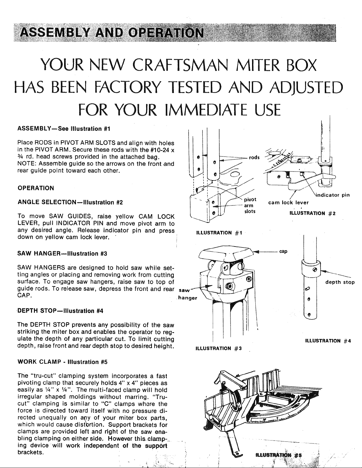
ASSEMBLY--See Illustration #1
Place RODS in PIVOT ARMSLOTS and align with holes
in the PIVOT ARM. Secure these rods with the #10-24 x
3/4rd. head screws provided in the attached bag.
NOTE: Assemble guide so the arrows on the front and
rear guide point toward each other.
OPERATION
ANGLE SELECTION--Illustration #2
To move SAW GUIDES, raise yellow CAM LOCK
LEVER, pull INDICATOR PIN and move pivot arm to
any desired angle. Release indicator pin and press
down on yellow cam lock lever.
t
._ rods
ILLUSTRATION #1
SAW HANGER--Illustration #3 j --
SAW HANGERS are designed to hold saw while set-
ting angles or placing and removing work from cutting
surface. To engage saw hangers, raise saw to top of
guide rods. To release saw, depress the front and rear saw- _T_j _-
CAP.. hanger "..__
'rl
DEPTH STOPmlllustration #4
The DEPTH STOP prevents any possibility of the saw
striking the miter box and enables the operator to reg-
ulate the depth of any particular cut. To limit cutting
depth, raise front and rear depth stop to desired height. ILLUSTRATION#3
ndicator pin
cam lock lever
IL'LUSTRATION #2
cap
depth stop
ILLUSTRATION #4
WORK CLAMP - Illustration #5
The "tru-cut" clamping system incorporates a fast
pivoting clamp that securely holds 4" x 4" pieces as
easily as 1/4" x 1/4". The multi-faced clamp will hold
irregular shaped moldings without marring. "Tru-
cut" clamping is similar to "C" clamps where the
force is directed toward itself with no pressure di-
rected unequally on a_y of your miter box parts,
which would cause distertion. Support brackets for
clamps are provided left and right of the saw ena-
bling clamping on either side, However thisclamp=
ing device will work independent of the support
brackets.
'i!_i
Loading ...
Loading ...
Loading ...