V2.00.000
06-10-2020

i
LAUNCH Creader Professional CRP123 User's Manual
Trademark Information
LAUNCH is a registered trademark of LAUNCH TECH CO., LTD. (LAUNCH)
in China and other countries. All other LAUNCH trademarks, service marks,
domain names, logos and company names referred to in this manual are either
trademarks, registered trademarks, service marks, domain names, logos and
company names of or are otherwise the property of LAUNCH or its affiliates.
In countries where any of the LAUNCH trademarks, service marks, domain
names, logos and company names are not registered, LAUNCH claims other
rights associated with unregistered trademarks, service marks, domain names,
logos and company names. Other products or company names referred to in
this manual may be trademarks of their respective owners. You may not use any
trademark, service mark, domain name, logo, or company name of LAUNCH or
any third party without permission from the owner of the applicable trademark,
service mark, domain name, logo, or company name. You may contact LAUNCH
at www.cnlaunch.com, or write to LAUNCH TECH. CO., LTD., Launch Industrial
Park, North of Wuhe Avenue, Banxuegang, Bantian, Longgang, Shenzhen,
Guangdong, P.R. China, to request written permission to use Materials on this
manual for purposes or for all other questions relating to this manual.
Copyright Information
Copyright © 2013 by LAUNCH TECH. CO., LTD. All rights reserved. No part of
this publication may be reproduced, stored in a retrieval system, or transmitted in
any form or by any means, electronic, mechanical, photocopying and recording
or otherwise, without the prior written permission of LAUNCH. The information
contained herein is designed only for the use of this unit. LAUNCH is not
responsible for any use of this information as applied to other units.

ii
LAUNCH Creader Professional CRP123 User's Manual
End User License Agreement
IMPORTANT: PLEASE READ THIS END USER LICENSE AGREEMENT
CAREFULLY. USING LAUNCH OR LAUNCH-SUPPLIED PRODUCTS AND
SOFTWARE CONSTITUTES ACCEPTANCE OF THIS AGREEMENT.
LAUNCH IS WILLING TO LICENSE THE PRODUCTS, INFORMATION,
SOFTWARE AND DOCUMENTS (COLLECTIVELY, “MATERIALS”) TO YOU
ONLY UPON THE CONDITION THAT YOU ACCEPT ALL OF THE TERMS
CONTAINED IN THIS LICENSE AGREEMENT. BY USING THE MATERIALS,
YOU ARE BINDING YOURSELF AND THE BUSINESS ENTITY THAT YOU
REPRESENT (COLLECTIVELY, “CUSTOMER”) TO THIS AGREEMENT. IF
YOU DO NOT AGREE TO ALL OF THE TERMS OF THIS AGREEMENT, THEN
LAUNCH IS UNWILLING TO LICENSE THE MATERIALS TO YOU AND DO
NOT USE THE PRODUCTS AND DOWNLOAD OR INSTALL THE SOFTWARE.
The following terms of this End User License Agreement (“Agreement”) govern
Customer’s access and use of the product, except to the extent there is a
separate signed agreement between Customers and LAUNCH governing
Customer’s use.
License
Conditioned upon compliance with the terms and conditions of this Agreement,
LAUNCH TECH. CO., LTD., or its subsidiary licensing the Materials instead of
LAUNCH, grants to Customer a nonexclusive and nontransferable license to use
for Customer’s internal business purposes the Materials and the Document for
which Customer has paid the required license fees. “Document” means written
information (whether contained in user or technical manuals, training materials,
specications or otherwise) specically pertaining to the equipment and made
available by LAUNCH with the equipment in any manner (including on CD-Rom,
or on-line).
Unless otherwise expressly provided in the Document, Customer shall use
the Software solely as embedded in, for execution on or (where the applicable
document permits installation on non-LAUNCH equipment) for communication
with LAUNCH equipment owned or leased by Customer and used for
Customer’s internal business purposes.
Note: For evaluation or beta copies for which LAUNCH does not charge a
license fee, the above requirement to pay license fees does not apply.
General Limitations
This is a license, not a transfer of title, to the materials, and LAUNCH retains
ownership of all copies of the Materials. Customer acknowledges that the

iii
LAUNCH Creader Professional CRP123 User's Manual
Materials contain trade secrets of LAUNCH, its suppliers or licensors, including
but not limited to the specic internal designed structure of individual programs
and associated interface information. Accordingly, except as otherwise expressly
provided under this Agreement, Customer shall have no right and Customer
specically agrees not to:
(i) Transfer, assign or sublicense its license rights to any other person or entity,
or use the Materials on unauthorized or secondhand LAUNCH equipment, and
Customer acknowledges that any attempted transfer, assignment, sublicense or
use shall be void;
(ii) Make error corrections to or otherwise modify or adapt the Materials or create
derivative works based upon the Materials, or permit third parties to do the
same;
(iii) Reverse engineer or decompile, decrypt, disassemble or otherwise reduce
the Materials to human-readable form, except to the extent otherwise expressly
permitted under applicable law notwithstanding this restriction;
(iv) Use or permit the Materials to be used to perform services for third parties,
whether on a service bureau or time sharing basis or otherwise, without the
express written authorization of LAUNCH;
(v) Disclose, provide, or otherwise make available trade secrets contained within
the Materials in any form to any third party without the prior written consent of
LAUNCH. Customer shall implement reasonable security measures to protect
such trade secrets.
To the extent required by law, and at Customer’s written request, LAUNCH
shall provide Customer with the interface information needed to achieve
interoperability between the Materials and another independently created
program, on payment of LAUNCH’s applicable fee, if any. Customer shall
observe strict obligations of confidentiality with respect to such information
and shall use such information in compliance with any applicable terms and
conditions upon which LAUNCH makes such information available.
Software, Upgrades and Additional Copies
For purposes of this Agreement, “Software” shall include (and the terms and
conditions of this Agreement shall apply to) computer programs, including
firmware, as provided to Customer by LAUNCH or an authorized LAUNCH
reseller, and any upgrades, updates, bug fixes or modified versions thereto
(collectively, “Upgrades”) or backup copies of the Software licensed or provided
to Customer by LAUNCH or an authorized LAUNCH reseller.
NOTWITHSTANDING ANY OTHER PROVISION OF THIS AGREEMENT:
(1) CUSTOMER HAS NO LICENSE OR RIGHT TO USE ANY ADDITIONAL

iv
LAUNCH Creader Professional CRP123 User's Manual
COPIES OR UPGRADES UNLESS CUSTOMER, AT THE TIME OF ACQUIRING
SUCH COPY OR UPGRADE, ALREADY HOLDS A VALID LICENSE TO THE
ORIGINAL SOFTWARE; (2) USE OF UPGRADES IS LIMITED TO LAUNCH
EQUIPMENT FOR WHICH CUSTOMER IS THE ORIGINAL END USER
PURCHASER OR LESSEE OR WHO OTHERWISE HOLDS A VALID LICENSE
TO USE THE SOFTWARE WHICH IS BEING UPGRADED; AND (3) THE
MAKING AND USE OF ADDITIONAL COPIES IS LIMITED TO NECESSARY
BACKUP PURPOSES ONLY.
Proprietary Notices
Customer agrees to maintain and reproduce all copyright and other proprietary
notices on all copies, in any form, of the Materials in the same form and manner
that such copyright and other proprietary notices are included on the Materials.
Except as expressly authorized in this Agreement, Customer shall not make
any copies or duplicates of any Materials without the prior written permission of
LAUNCH.
Term and Termination
This Agreement and the license granted herein shall remain effective until
terminated. Customer may terminate this Agreement and the license at any
time by destroying all copies of Materials and any Document. Customer’s
rights under this Agreement will terminate immediately without notice from
LAUNCH if Customer fails to comply with any provision of this Agreement. Upon
termination, Customer shall destroy all copies of Software in its possession or
control. All condentiality obligations of Customer and all limitations of liability
and disclaimers and restrictions of warranty shall survive termination of this
Agreement.
Customer Records
Customer grants to LAUNCH and its independent accountants the right to
examine Customer’s books, records and accounts during Customer’s normal
business hours to verify compliance with this Agreement. In the event such audit
discloses non-compliance with this Agreement, Customer shall promptly pay to
LAUNCH the appropriate license fees, plus the reasonable cost of conducting
the audit.
Export
Software, including technical data, may be subject to PRC export control laws,
including the PRC. Export Administration Act and its associated regulations, and
may be subject to export or import.

v
LAUNCH Creader Professional CRP123 User's Manual
General Notice
• Other product names used herein are for identification purposes only and
may be trademarks of their respective owners. LAUNCH disclaims any and all
rights in those marks.
• There is a possibility that this unit is inapplicable to some of the vehicle
models or systems listed in the diagnosis section due to different countries,
areas, and/or years. Do not hesitate to contact LAUNCH if you come across
such questions. We are to help you solve the problem as soon as possible.
Disclaimer
• To take full advantage of the unit, you should be familiar with the engine.
• All information, illustrations, and specications contained in this manual are
based on the latest information available at the time of publication. The right
is reserved to make change at any time without notice.
• Neither LAUNCH nor its afliates shall be liable to the purchaser of this unit
or third parties for damages, losses, costs or expenses incurred by purchaser
or third parties as a result of: accident, misuse, or abuse of this unit, or
unauthorized modifications, repairs, or alterations to this unit, or failure to
strictly comply with LAUNCH operating and maintenance instructions.
• LAUNCH shall not be liable for any damages or problems arising from the
use of any options or any consumable products other than those designated
as Original LAUNCH Products or LAUNCH Approved Products by LAUNCH.
Safety Precautions and Warnings
To prevent personal injury or damage to vehicles and/or the CRP123, please
read this user’s manual first carefully and observe the following safety
precautions at a minimum whenever working on a vehicle:
• Always perform automotive testing in a safe environment.
• Do not attempt to operate or observe the tool while driving a vehicle.
Operating or observing the tool will cause driver distraction and could cause a
fatal accident.
• Wear safety eye protection that meets ANSI standards.
• Keep clothing, hair, hands, tools, test equipment, etc. away from all moving or
hot engine parts.
• Operate the vehicle in a well-ventilated work area: Exhaust gases are
poisonous.
• Put blocks in front of the drive wheels and never leave the vehicle unattended
while running tests.
• Use extreme caution when working around the ignition coil, distributor cap,
ignition wires and spark plugs. These components create hazardous voltages
when the engine is running.

vi
LAUNCH Creader Professional CRP123 User's Manual
• Put the transmission in P (for A/T) or N (for M/T) and make sure the parking
brake is engaged.
• Keep a re extinguisher suitable for gasoline/chemical/ electrical res nearby.
• Don’t connect or disconnect any test equipment while the ignition is on or the
engine is running.
• Keep the CRP123 dry, clean, free from oil/water or grease. Use a mild
detergent on a clean cloth to clean the outside of the CRP123, when
necessary.
FCC Statement
This device complies with part 15 of the FCC Rules. Operation is subject to the
following two conditions: (1) This device may not cause harmful interference,
and (2) this device must accept any interference received, including interference
that may cause undesired operation.

vii
LAUNCH Creader Professional CRP123 User's Manual
Table of Contents
1. Introduction .....................................................................................................1
2. General Information ..........................................................................................1
2.1 On-Board Diagnostics (OBD) II ..................................................................1
2.2 Diagnostic Trouble Codes (DTCs)..............................................................2
2.3 Location of the Data Link Connector (DLC) ...............................................2
2.4 OBD II Readiness Monitors ........................................................................ 3
2.5 OBD II Monitor Readiness Status ..............................................................4
2.6 OBD II Denitions ....................................................................................... 4
3. Product Descriptions .....................................................................................6
3.1 Outline of CRP123 .....................................................................................6
3.2 Specications .............................................................................................7
3.3 Accessories Included..................................................................................7
4. Connection ......................................................................................................8
4.1 Preparation .................................................................................................8
4.2 Install TF card .............................................................................................8
4.3 Connect CRP123 .......................................................................................8
5. Diagnose .......................................................................................................10
5.1 OBDII/EOBD Diagnosing .........................................................................10
5.1.1 Read Codes ....................................................................................11
5.1.2 Erase Codes ...................................................................................13
5.1.3 I/M Readiness ................................................................................. 14
5.1.4 Data Stream....................................................................................15
5.1.5 View Freeze Frame ........................................................................17
5.1.6 O2 sensor test ................................................................................18
5.1.7 On-board monitor test ..................................................................... 19
5.1.8 EVAP System Test ..........................................................................20
5.1.9 Vehicle Info .....................................................................................21
5.2 System Diagnosing ..................................................................................21
5.3 Review .....................................................................................................24
6 Settings ..........................................................................................................25
6.1 Language .................................................................................................25
6.2 Unit of Measure ........................................................................................26
6.3 Beeper ......................................................................................................26
6.4 Record Mode ............................................................................................26

viii
LAUNCH Creader Professional CRP123 User's Manual
7. Help ................................................................................................................28
7.1 DLC Location Information........................................................................ 28
7.2 DTC Library ............................................................................................. 28
7.3 Abbreviation............................................................................................. 29
7.4 Tool Information ....................................................................................... 30
7.5 About OBD .............................................................................................. 30
8. Update ...........................................................................................................31
9. FAQ ................................................................................................................35

1
LAUNCH Creader Professional CRP123 User's Manual
1. Introduction
The Creader Professional CRP123 is specially developed by LAUNCH, which
supports all 10 modes of OBD II test for a complete diagnosis. Featuring the
3.5” TFT color display, it enables users to read/clear DTCs, record, save and
playback data in live graphic display. The CRP123 is also very easy to use. With
built-in help menus and code denitions, diagnosing and repairing that dreaded
Check Engine Light is now easier than ever!
Moreover, CRP123 also features the following bi-directional “special tests”:
EVAP, O2 Sensor, I/M Readiness, MIL Status, VIN Info, and On-board monitors
testing.
It can be connected to PC through the USB cable for upgrade to keep updated
with the latest software version.
Notice: CRP123 may automatically reset while being disturbed by strong static
electricity. THIS IS A NORMAL REACTION.
2. General Information
2.1 On-Board Diagnostics (OBD) II
The first generation of On-Board Diagnostics (called OBD I) was developed
by the California Air Resources Board (ARB) and implemented in 1988 to
monitor some of the emission control components on vehicles. As technology
evolved and the desire to improve the On-Board Diagnostic system increased,
a new generation of On-Board Diagnostic system was developed. This second
generation of On-Board Diagnostic regulations is called “OBD II”.
The OBD II system is designed to monitor emission control systems and key
engine components by performing either continuous or periodic tests of specic
components and vehicle conditions. When a problem is detected, the OBD II
system turns on a warning lamp (MIL) on the vehicle instrument panel to alert
the driver typically by the phrase of “Check Engine” or “Service Engine Soon”.
The system will also store important information about the detected malfunction
so that a technician can accurately nd and x the problem. Here below follow
three pieces of such valuable information:
1) Whether the Malfunction Indicator Light (MIL) is commanded ‘on’ or ‘off’;
2) Which, if any, Diagnostic Trouble Codes (DTCs) are stored;
3) Readiness Monitor status.
2
LAUNCH Creader Professional CRP123 User's Manual
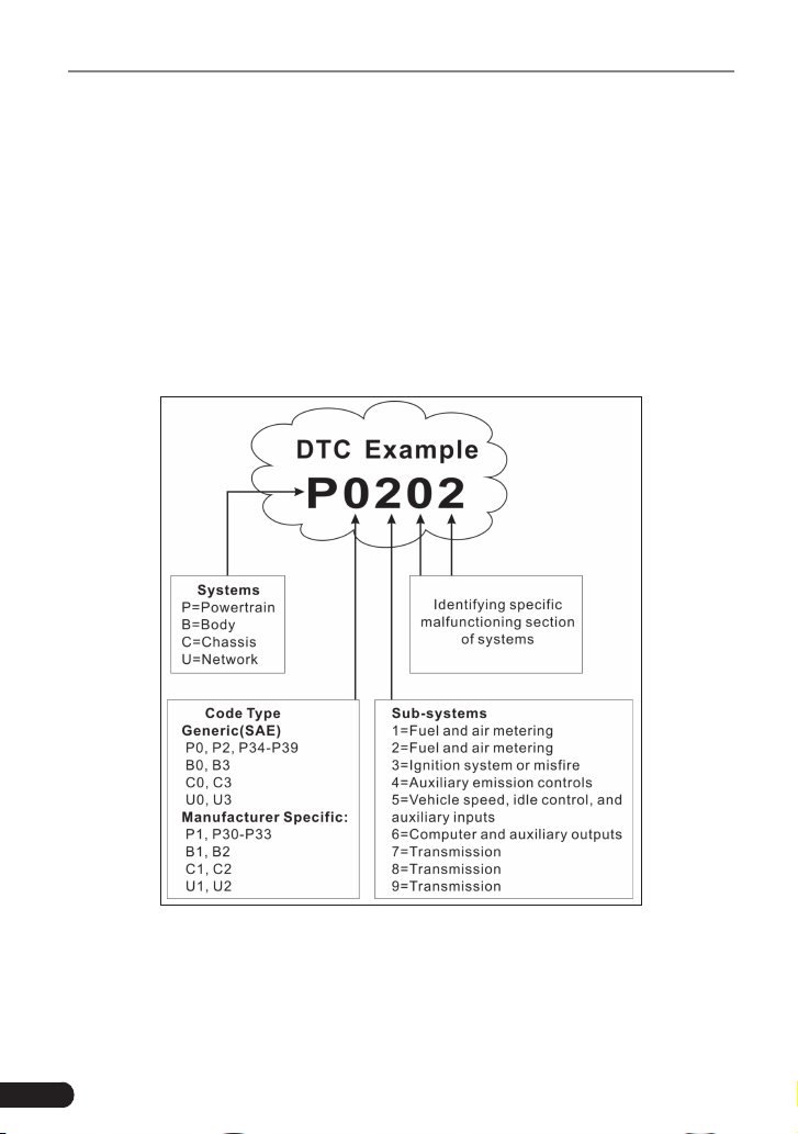
2.2 Diagnostic Trouble Codes (DTCs)
OBD II Diagnostic Trouble Codes are codes that are stored by the on-board
computer diagnostic system in response to a problem found in the vehicle. These
codes identify a particular problem area and are intended to provide you with a
guide as to where a fault might be occurring within a vehicle. OBD II Diagnostic
Trouble Codes consist of a five-digit alphanumeric code. The first character,
a letter, identifies which control system sets the code. The second character,
a number, 0-3; other three characters, a hex character, 0-9 or A-F provide
additional information on where the DTC originated and the operating conditions
that caused it to set. Here below is an example to illustrate the structure of the
digits:
Figure 2-1
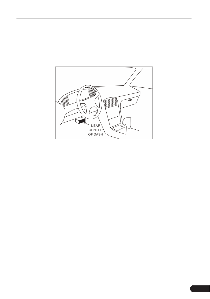
2.3 Location of the Data Link Connector (DLC)
The DLC (Data Link Connector or Diagnostic Link Connector) is the standardized
16-cavity connector where diagnostic code readers interface with the vehicle’s
3
LAUNCH Creader Professional CRP123 User's Manual
on-board computer. The DLC is usually located 12 inches from the center of the
instrument panel (dash), under or around the driver’s side for most vehicles. If
Data Link Connector is not located under dashboard, a label should be there
telling location. For some Asian and European vehicles, the DLC is located
behind the ashtray and the ashtray must be removed to access the connector. If
the DLC cannot be found, refer to the vehicle’s service manual for the location.
Figure 2-2
2.4 OBD II Readiness Monitors
An important part of a vehicle’s OBD II system is the Readiness Monitors, which
are indicators used to find out if all of the emissions components have been
evaluated by the OBD II system. They are running periodic tests on specific
systems and components to ensure that they are performing within allowable
limits.
Currently, there are eleven OBD II Readiness Monitors (or I/M Monitors) dened
by the U.S. Environmental Protection Agency (EPA). Not all monitors are
supported in every vehicles and the exact number of monitors in any vehicle
depends on the motor vehicle manufacturer’s emissions control strategy.
Continuous Monitors -- Some of the vehicle components or systems are
continuously tested by the vehicle’s OBD II system, while others are tested
only under specific vehicle operating conditions. The continuously monitored
components listed below are always ready:
1. Misre
2. Fuel System
3. Comprehensive Components (CCM)
Once the vehicle is running, the OBD II system is continuously checking the
above components, monitoring key engine sensors, watching for engine misre,

4
LAUNCH Creader Professional CRP123 User's Manual
and monitoring fuel demands.
Non-Continuous Monitors -- Unlike the continuous monitors, many emissions
and engine system components require the vehicle to be operated under
specic conditions before the monitor is ready. These monitors are termed non-
continuous monitors and are listed below:
1) EGR System
2) O2 Sensors
3) Catalyst
4) Evaporative System
5) O2 Sensor Heater
6) Secondary air Injection
7) Heated Catalyst
8) A/C system
2.5 OBD II Monitor Readiness Status
OBD II systems must indicate whether or not the vehicle’s PCM’s monitor
system has completed testing on each component. Components that have been
tested will be reported as “Ready”, or “Complete”, meaning they have been
tested by the OBD II system. The purpose of recording readiness status is to
allow inspectors to determine if the vehicle’s OBD II system has tested all the
components and/or systems.
The powertrain control module (PCM) sets a monitor to “Ready” or “Complete”
after an appropriate drive cycle has been performed. The drive cycle that
enables a monitor and sets readiness codes to “Ready” varies for each
individual monitor. Once a monitor is set as “Ready” or “Complete”, it will remain
in this state. A number of factors, including erasing of diagnostic trouble codes
(DTCs) with a code reader or a disconnected battery, can result in Readiness
Monitors being set to “Not Ready”. Since the three continuous monitors are
constantly evaluating, they will be reported as “Ready” all of the time. If testing
of a particular supported non-continuous monitor has not been completed, the
monitor status will be reported as “Not Complete” or “Not Ready.”
In order for the OBD monitor system to become ready, the vehicle should be
driven under a variety of normal operating conditions. These operating conditions
may include a mix of highway driving and stop and go, city type driving, and at
least one overnight-off period. For specic information on getting your vehicle’s
OBD monitor system ready, please consult your vehicle owner’s manual.
2.6 OBD II Denitions
Powertrain Control Module (PCM) -- OBD II terminology for the on-board

5
LAUNCH Creader Professional CRP123 User's Manual
computer that controls engine and drive train.
Malfunction Indicator Light (MIL) -- Malfunction Indicator Light (Service Engine
Soon, Check Engine) is a term used for the light on the instrument panel. It
is to alert the driver and/or the repair technician that there is a problem with
one or more of vehicle’s systems and may cause emissions to exceed federal
standards. If the MIL illuminates with a steady light, it indicates that a problem
has been detected and the vehicle should be serviced as soon as possible.
Under certain conditions, the dashboard light will blink or ash. This indicates a
severe problem and flashing is intended to discourage vehicle operation. The
vehicle onboard diagnostic system cannot turn the MIL off until the necessary
repairs are completed or the condition no longer exists.
DTC -- Diagnostic Trouble Codes (DTC) that identifies which section of the
emission control system has malfunctioned.
Enabling Criteria -- Also termed Enabling Conditions. They are the vehicle-
specic events or conditions that must occur within the engine before the various
monitors will set, or run. Some monitors require the vehicle to follow a prescribed
“drive cycle” routine as part of the enabling criteria. Drive cycles vary among
vehicles and for each monitor in any particular vehicle. Please refer to the
vehicle’s factory service manual for specic enabling procedures.
OBD II Drive Cycle -- A specific mode of vehicle operation that provides
conditions required to set all the readiness monitors applicable to the vehicle to
the “ready” condition. The purpose of completing an OBD II drive cycle is to force
the vehicle to run its onboard diagnostics. Some form of a drive cycle needs to
be performed after DTCs have been erased from the PCM’s memory or after
the battery has been disconnected. Running through a vehicle’s complete drive
cycle will “set” the readiness monitors so that future faults can be detected. Drive
cycles vary depending on the vehicle and the monitor that needs to be reset. For
vehicle specic drive cycle, consult the service manual.
Freeze Frame Data -- When an emissions related fault occurs, the OBD II
system not only sets a code but also records a snapshot of the vehicle operating
parameters to help in identifying the problem. This set of values is referred to
as Freeze Frame Data and may include important engine parameters such as
engine RPM, vehicle speed, air ow, engine load, fuel pressure, fuel trim value,
engine coolant temperature, ignition timing advance, or closed loop status.
Fuel Trim (FT) - Feedback adjustments to the base fuel schedule. Short-term
fuel trim refers to dynamic or instantaneous adjustments. Long-term fuel trim
refers to much more gradual adjustments to the fuel calibration schedule than
short-term trim adjustments. These long-term adjustments compensate for
vehicle differences and gradual changes that occur over time.
6
LAUNCH Creader Professional CRP123 User's Manual
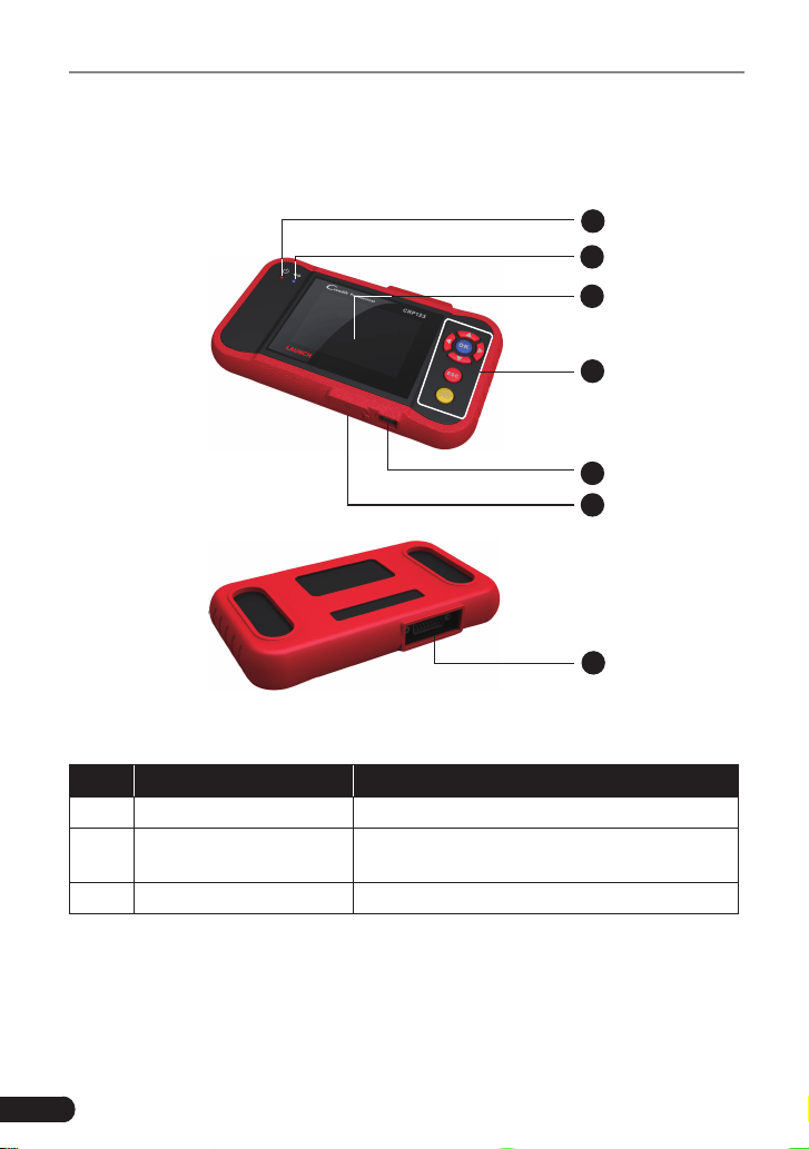
3. Product Descriptions
3.1 Outline of CRP123
1
2
3
4
5
6
7
Figure 3-1
No. Name Descriptions
1 Power indicator It will light up while CRP123 is energized.
2
Communication
indicator
It will ash when CRP123 is communicating
with ECU.
3 LCD Indicates test results.
7
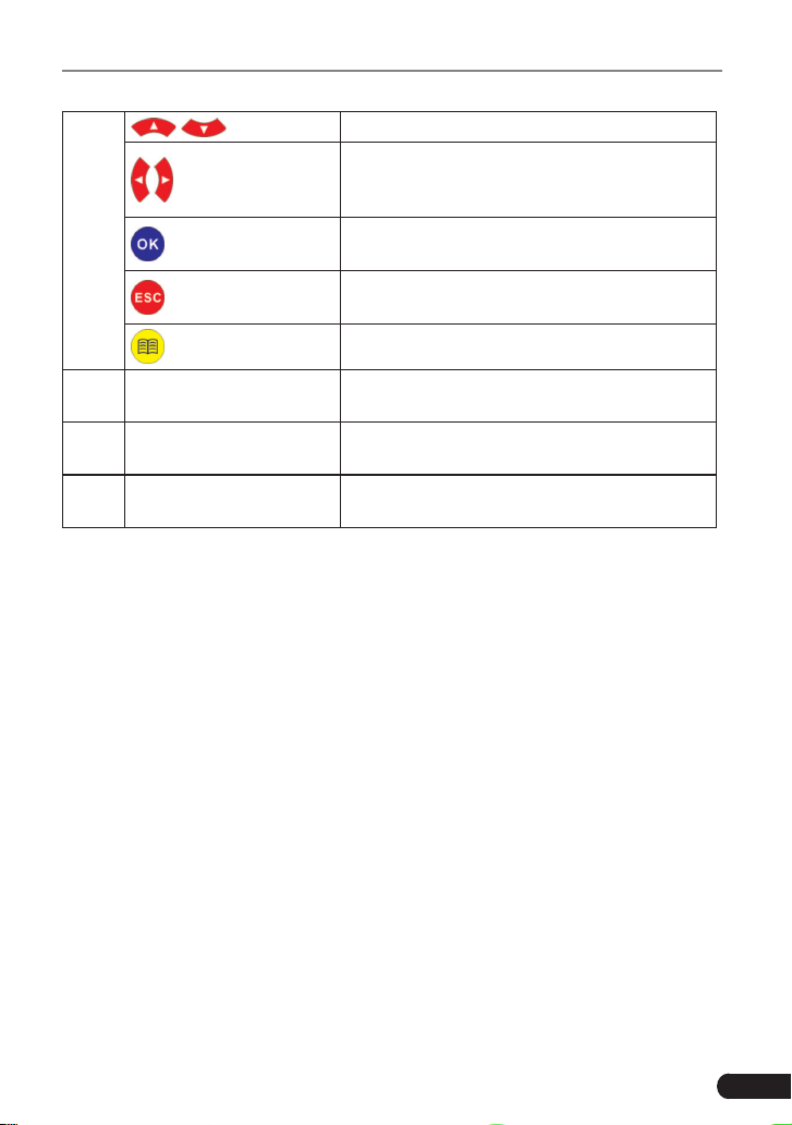
LAUNCH Creader Professional CRP123 User's Manual
4
/ Move cursor up or down for selection.
/
Move cursor left or right for selection; Or
turn page up or down when more than one
page is displayed.
Conrms a selection (or action) from a menu
list.
Exit the current program or return to the
previous screen.
To retrieve the DTCs in the database.
5 USB port
To connect to PC to upload data or print test
results.
6 TF card slot
Insert the TF card into it to read or write the
data/le stored in TF card.
7 OBD-16 connector
To connect to vehicle's DLC(Data Link
Connector) via diagnostic cable.
3.2 Specications
• Screen: 3.5” TFT LCD display
• Working voltage: 9~18V
• Working current: <600mA
• Working temperature: 0 to 50°C (32 to 122 F°)
• Storage temperature: -20 to 70°C (-4 to 158 F°)
• Working humidity: 10%~90%
• Storage humidity: <80%
3.3 Accessories Included
1. User’s Manual
2. TF card
3. TF card reader
4. USB cable

8
LAUNCH Creader Professional CRP123 User's Manual
4. Connection
4.1 Preparation
1. Normal testing conditions
• Turn on the vehicle power supply.
• The voltage of vehicle battery should be 11-14V and the working voltage of
CRP123 is 12V.
• Throttle should be closed at its close position.
• Ignition timing and idle speed should be within specified range; water
and transmission oil temperature are within normal working range (water
temperature is 90-110
o
C and transmission oil temperature is 50-80
o
C).
2. Select testing connectors
If CRP123 is testing vehicles equipped with universal OBD II 16 PIN diagnostic
socket, please use the included DBScar diagnostic connector. (For vehicles with
non-OBD II 16 PIN diagnostic socket, a non-16 PIN connector is required.)
4.2 Install TF card
1) Take out the TF card from package box.
2) Insert the TF card into the CRP123 TF card slot perpendicularly. Make sure is
fully inserted in the right place with the “micro” label facing upward.
Note: You can hear a clicking sound if you insert the TF card in the right place.
Press the card slightly, it will be ejected automatically.
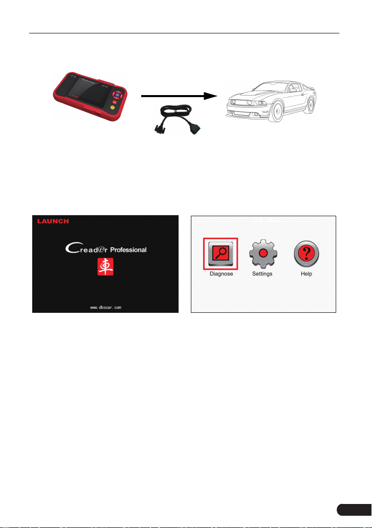
4.3 Connect CRP123
1. Turn the ignition off.
2. Locate vehicle’s DLC socket: it provides standard 16 pins and is generally
located on driver’s side, about 12 inch away from the center of dashboard.
See Figure 2-2. If DLC is not equipped under dashboard, an label indicating
its position will be given. In case no DLC is found, please refer to Automobile
Repair Manual.
3. Select the desired diagnostic adaptor according to your vehicle’s DLC. Plug
one end the diagnostic cable into the OBD II 16 pin connector of CRP123,
and connect the other end to the vehicle’s DLC.
9
LAUNCH Creader Professional CRP123 User's Manual
Plug one end of the diagnostic
cable to diagnostic interface,
then connect the other end to
vehicle's DLC.
Figure 4-1
4. Turn the ignition on. Engine can be off or running.
5. After nishing, the system will start initializing. After initialization, the system
will enter the main menu interface. See Figure 4-2 & Figure 4-3.
Figure 4-2 Figure 4-3
CAUTION: Don’t connect or disconnect any test equipment with ignition on or
engine running.
10
LAUNCH Creader Professional CRP123 User's Manual
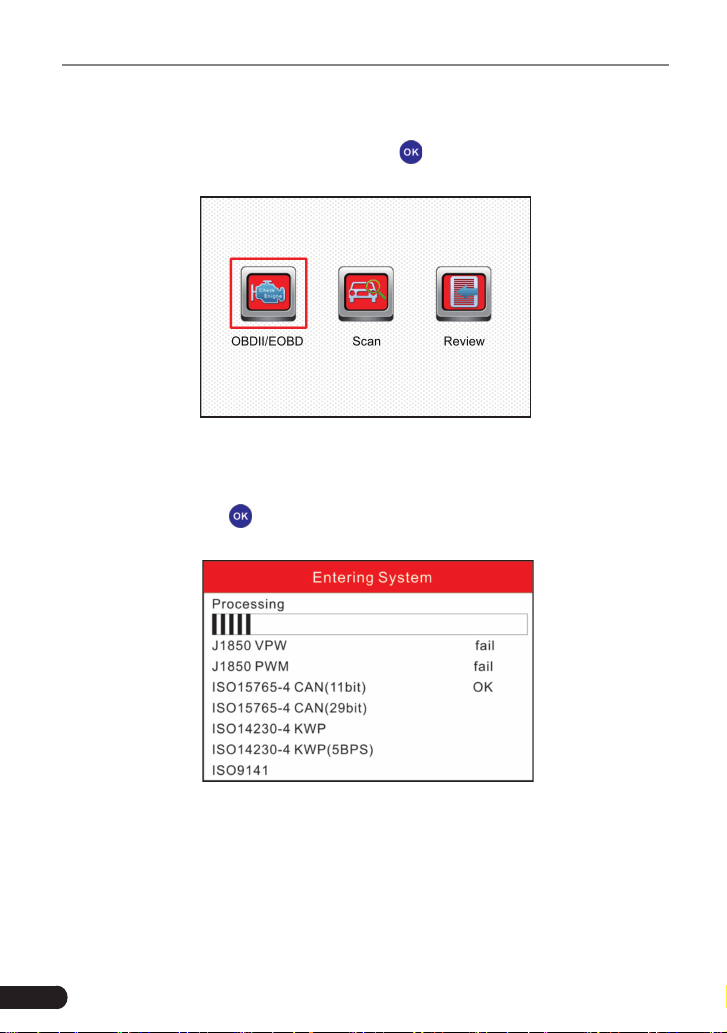
5. Diagnose
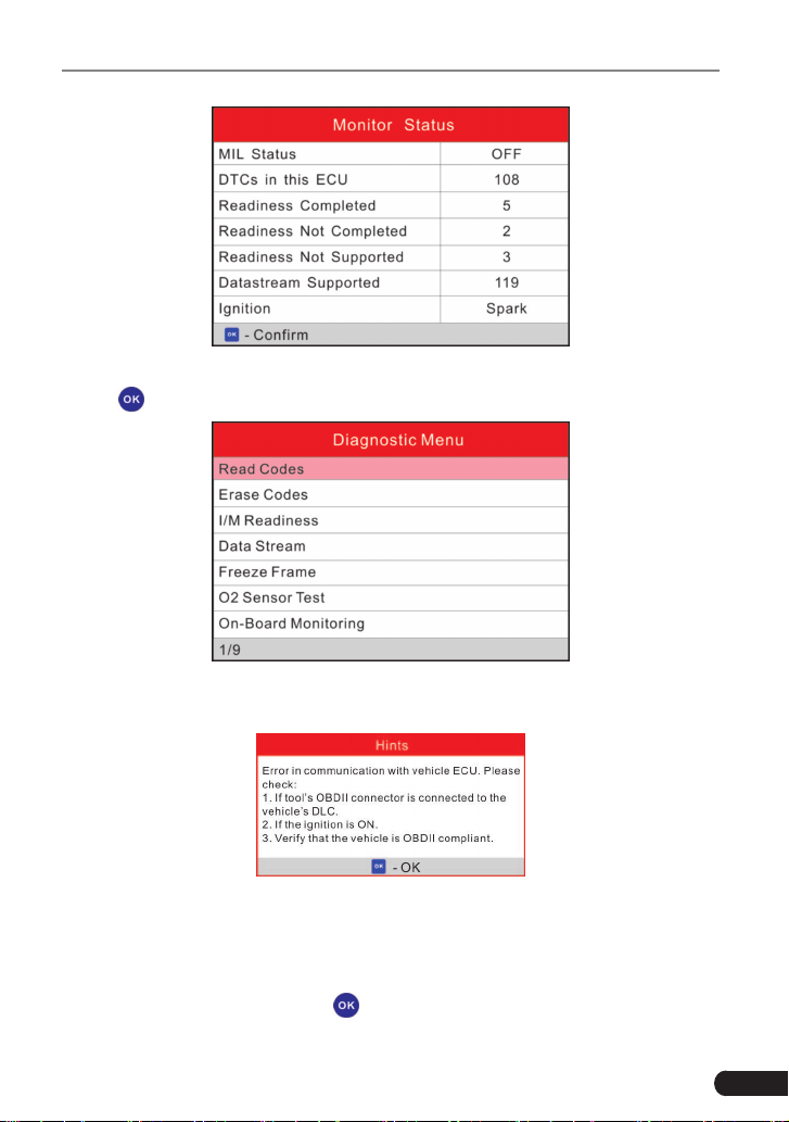
Select [Diagnose] in Main Menu and press [
], the screen will display Monitor
Status interface as following gure 5-1:
Figure 5-1
5.1 OBDII/EOBD Diagnosing
In Figure 5-1, press [
] to enter system, the screen will display as following
gure 5-2:
Figure 5-2
After entering, the screen will automatically enter the screen as shown in gure
5-3:
11
LAUNCH Creader Professional CRP123 User's Manual
Figure 5-3
Press [
], a screen similar to Figure 5-4 will appear:
Figure 5-4
If it fails to enter the system, a prompt message box will appear:
Figure 5-5
Follow the on-screen instructions to check the possible cause and retry it.
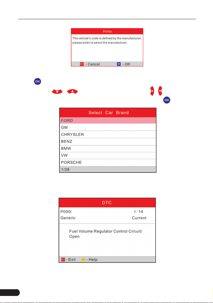
5.1.1 Read Codes
Select [Read Codes] and press [ ]. A dialog box similar to Figure 5-6 will pop
up:
12
LAUNCH Creader Professional CRP123 User's Manual
Figure 5-6
Press [
] to enter to select the manufacturer. Figure 5-7 will be shown on the
screen. Press [
]/[ ] to select different items; press [ ]/[ ] to turn to next
or previous page. After selecting the desired one, and then press [
] to conrm.
Figure 5-7
If some DTCs are found, the system will enter a screen similar to gure 5-8 will
appear:
Figure 5-8
1/14 indicates there are 14 codes total and now P0001 is the first code to
13
LAUNCH Creader Professional CRP123 User's Manual
display. The screen will also show the detailed description of the current DTC.
You can use [
] key to view the next code.
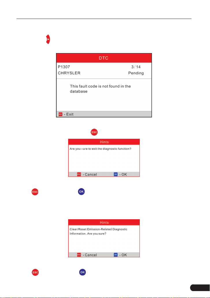
If the DTC can not be found, a screen similar to gure 5-9 will appear:
Figure 5-9
After viewing all the codes, press [
], a message box will appear on the box:
Figure 5-10
Press [
] to cancel; press [ ] to exit diagnostic function.
5.1.2 Erase Codes
Select [Erase Codes], the screen will display the interface as shown below:
Figure 5-11
Press [
] to cancel; press [ ] to erase DTC’s, and the screen will display the
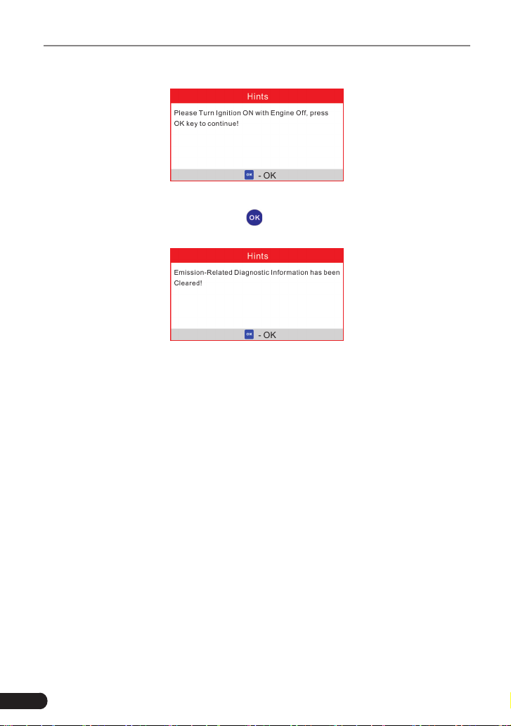
14
LAUNCH Creader Professional CRP123 User's Manual
interface as shown in Figure 5-12:
Figure 5-12
According to the above gure, press [
] to clear the DTC. If successful, gure
5-13 will appear on the screen.
Figure 5-13
Notes:
• Before performing this function, make sure to retrieve and record the trouble
codes.
• After clearing, you should retrieve trouble codes once more or turn ignition on
and retrieve codes again. If there are still some trouble codes in the system,
please troubleshoot the code using a factory diagnosis guide, then clear the
code and recheck.
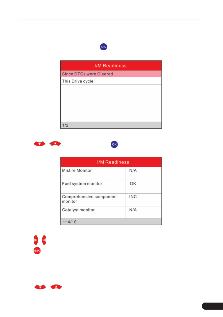
5.1.3 I/M Readiness
I/M refers to Inspection and Maintenance that is legislated by the Government
to meet federal clean-air standards. I/M Readiness indicates whether or not the
various emissions-related systems on the vehicle are operating properly and are
ready for Inspection and Maintenance testing.
The purpose of the I/M Readiness Monitor Status is to indicate which of the
vehicle’s Monitors have run and completed their diagnosis and testing (as
described in Chapter 2.5), and which ones have not yet run and completed
testing and diagnosis of their designated sections of the vehicle’s emissions
system.
The I/M Readiness Monitor Status function also can be used (after repair of
15
LAUNCH Creader Professional CRP123 User's Manual
a fault has been performed) to confirm that the repair has been performed
correctly, and/or to check for Monitor Run Status.
Select [I/M Readiness] and press [
], the screen will display the interface as
shown below:
Figure 5-14
Press [
]/[ ] to select and press [ ], the screen will display the interface
as shown below:
Figure 5-15
Press [
]/[ ] button to view other data of vehicle.
Press [
] to return to Diagnostic Menu.
N/A means not available on this vehicle; INC means incomplete or not ready and
OK means Completed or Monitor Ok.
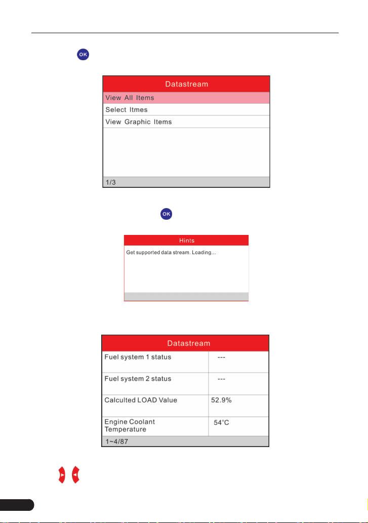
5.1.4 Data Stream
Press [
]/[ ] button to select Data Stream in Main Menu interface and
16
LAUNCH Creader Professional CRP123 User's Manual
then press [
] button to conrm, the screen will display the interface as shown
in gure 5-16:
Figure 5-16
Select [View All Items] and press [
] button, the screen will display the interface
as shown below:
Figure 5-17
A screen similar to gure 5-18 will appear.
Figure 5-18
Press [
]/[ ] button to view other data streams.
17
LAUNCH Creader Professional CRP123 User's Manual
Press [
] to return to Diagnostic Menu.
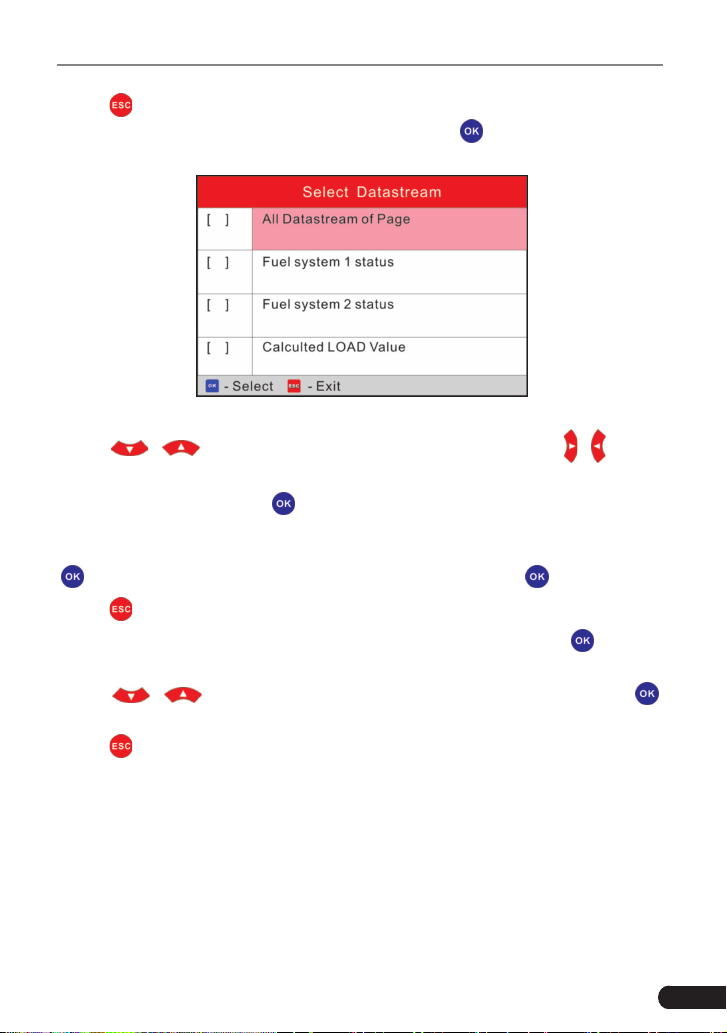
Select [Select Items] in Datastream menu and press [
], the screen will display
the interface as shown below:
Figure 5-19
Press [
]/[ ] button to select datastream items, and press [ ]/[ ] button
to turn page.
After selecting items, press [
], the screen will display the selected datastream
items.
To select all datastream of the current page, highlight the rst line and then press
[
],
will appear before all items. To deselect all, just press [ ] again.
Press [
] to return to Diagnostic Menu.
If [View Graphic Items] is selected in Datastream menu and press [
] to enter
the graphic items selection screen.
Press [
]/[ ] button to select single data stream items, and press [ ]
button, the screen will display the selected items of live graphic data.
Press [
] to return to Diagnostic Menu.
5.1.5 View Freeze Frame
When an emission-related fault occurs, certain vehicle conditions are recorded
by the on-board computer. This information is referred to as freeze frame data.
Freeze Data is a snapshot of the operating conditions at the time of an emission-
related fault.
Note: if DTCs were erased, Freeze Data may not be stored in vehicle memory
depending on vehicle.

18
LAUNCH Creader Professional CRP123 User's Manual
Select [Freeze Frame] in Diagnostic menuand press [
], the screen will display
the interface as shown below:
Figure 5-20
Press [
]/[ ] button to view the data.
Press [
] to return to Diagnostic Menu.
5.1.6 O2 sensor test
The results of O2 sensor test are not live values but instead the results of the
ECU’s last O2 sensor test. For live O2 sensor readings, refer to any of the live
sensor screens such as Graph Screen.
Not all test values are applicable to all vehicles. Therefore, the list generated
will vary depending on vehicle. In addition, not all vehicles support the Oxygen
Sensors screen.
For results of latest mandated on-board oxygen sensor monitoring test, see
Figure 5-21.
Figure 5-21
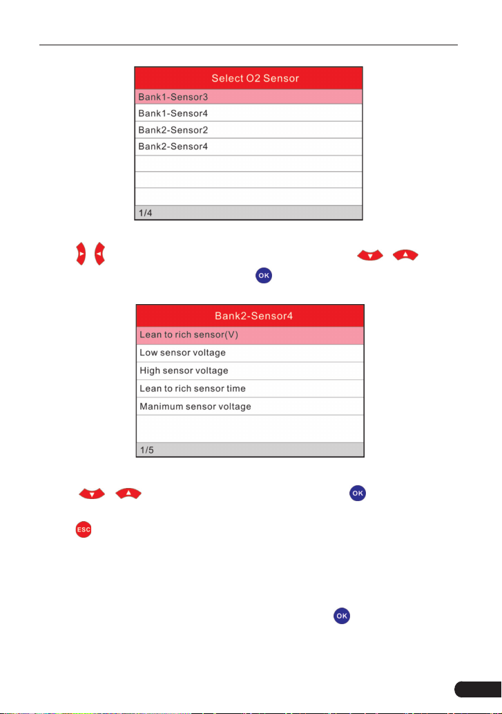
Select [O2 Sensor Test] in Diagnostic menu and press [
] and the screen will
display as shown below:
19
LAUNCH Creader Professional CRP123 User's Manual
Figure 5-22
Press [
]/[ ] button to turn to next or previous page. Press [ ]/[ ] button
to select the desired items, then press [
] button, the screen will display as
shown below:
Figure 5-23
Press [
]/[ ] button to select an item and press [ ], the screen will
display the test resut.
Press [
] to return to Diagnostic Menu.
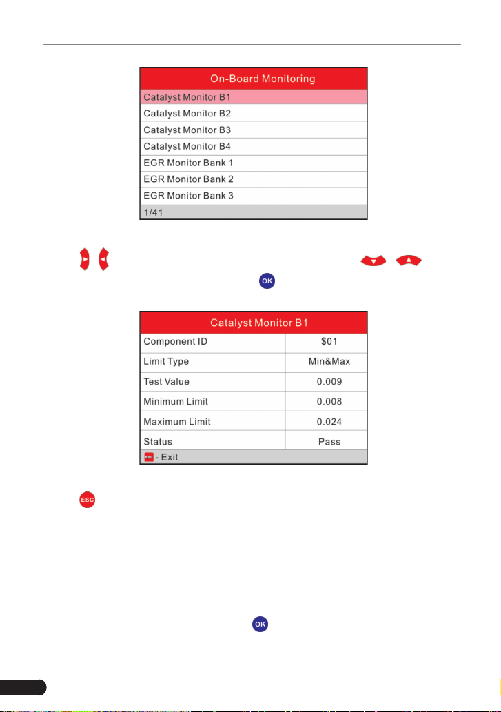
5.1.7 On-board monitor test
This function can be utilized to read the results of on-board diagnostic monitoring
tests for specic components/systems.
Select [On-board Monitoring] in main menu and press [
] and the screen will
display as shown below:
20
LAUNCH Creader Professional CRP123 User's Manual
Figure 5-24
Press [
]/[ ] button to turn to next or previous page. Press [ ]/[ ] button
to select the desired items, then press [
] button, the screen will display as
shown below:
Figure 5-25
Press [
] to return to Diagnostic Menu.
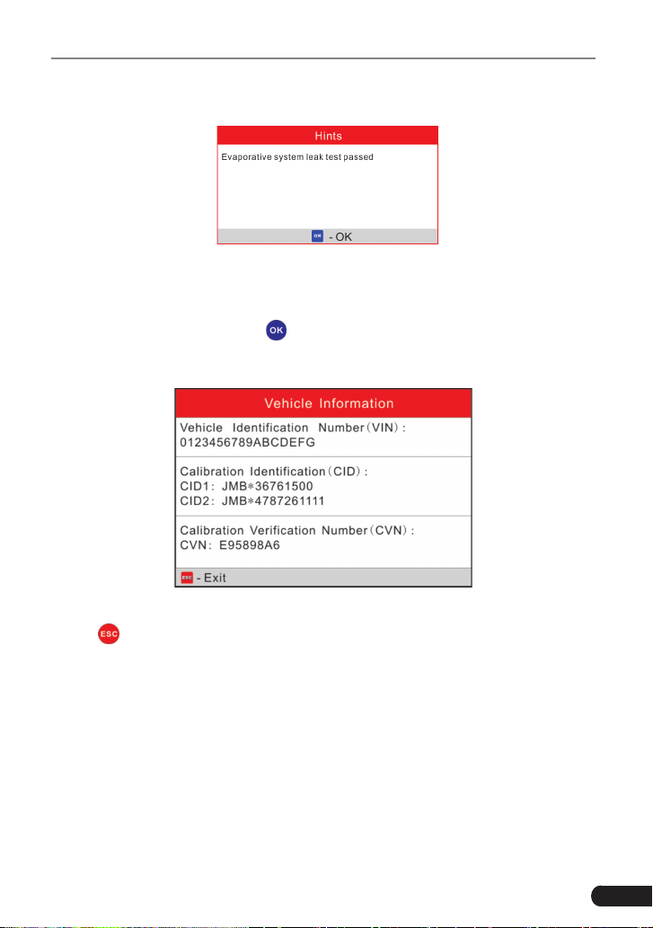
5.1.8 EVAP System Test
The EVAP test function lets you initiate a leak test for the vehicle’s EVAP system.
The CReaderVI does not perform the leak test, but signals to vehicle’s on-board
computer to initiate the test. Before using the system test function, refer to the
vehicle’s service repair manual to determine the procedures necessary to stop
the test.
Select [EVAP System Test] and press [
], the screen will display the relative
information about EVAP system. Some vehicle manufacturers do not allow
21
LAUNCH Creader Professional CRP123 User's Manual
external devices to control vehicle system. If the car supports this function, it will
display as below:
Figure 5-26
5.1.9 Vehicle Info
Select [Vehicle Info] and press [
], the screen will display the information, such
as VIN (Vehicle identication Number), CID (Calibration ID) and CVN (Calibration
verication number), as shown below:
Figure 5-27
Press [
] to return to Diagnostic Menu.
5.2 System Diagnosing
This function is specially designed to diagnose electronic control system of
single vehicle model which includes the following systems:
• Engine
• ABS(Anti-lock Brake System)
• AT(Automatic Transmission)
• SRS(Supplemental Restraint System)
22
LAUNCH Creader Professional CRP123 User's Manual
Notes:
• Before diagnosing, please make sure the diagnostic program corresponding to
certain vehicle model has been installed on your CRP123.
• For vehicles manufactured by different vendors, it is possible that it has
different diagnostic menus. For details, please follow the instructions on the
screen to proceed.
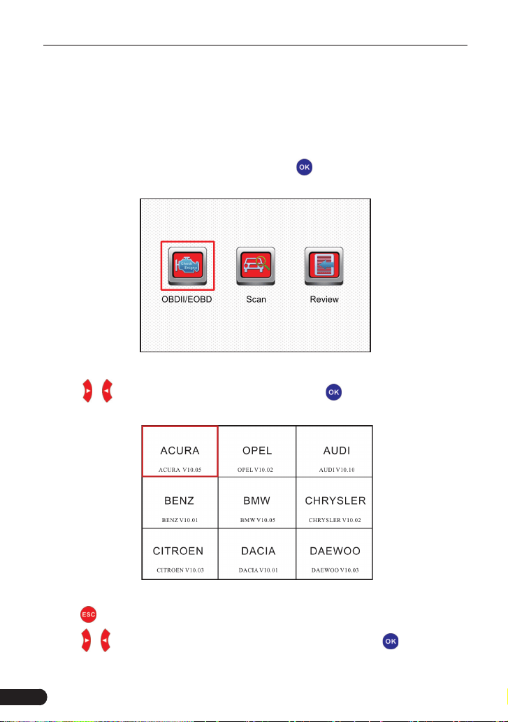
In main menu, select [Diagnose] and press [
] to confirm, the screen will
display as gure 5-28.
Figure 5-28
Press [
]/[ ] button to highlight [Scan] and press [ ], the system will enter
vehicle system selection interface. See Fig. 5-29.
Figure 5-29
Press [
] to return to Diagnose main menu.
Press [
]/[ ] button to highlight the desired vehicle and press [ ], the system
will enter vehicle system selection interface.
23
LAUNCH Creader Professional CRP123 User's Manual
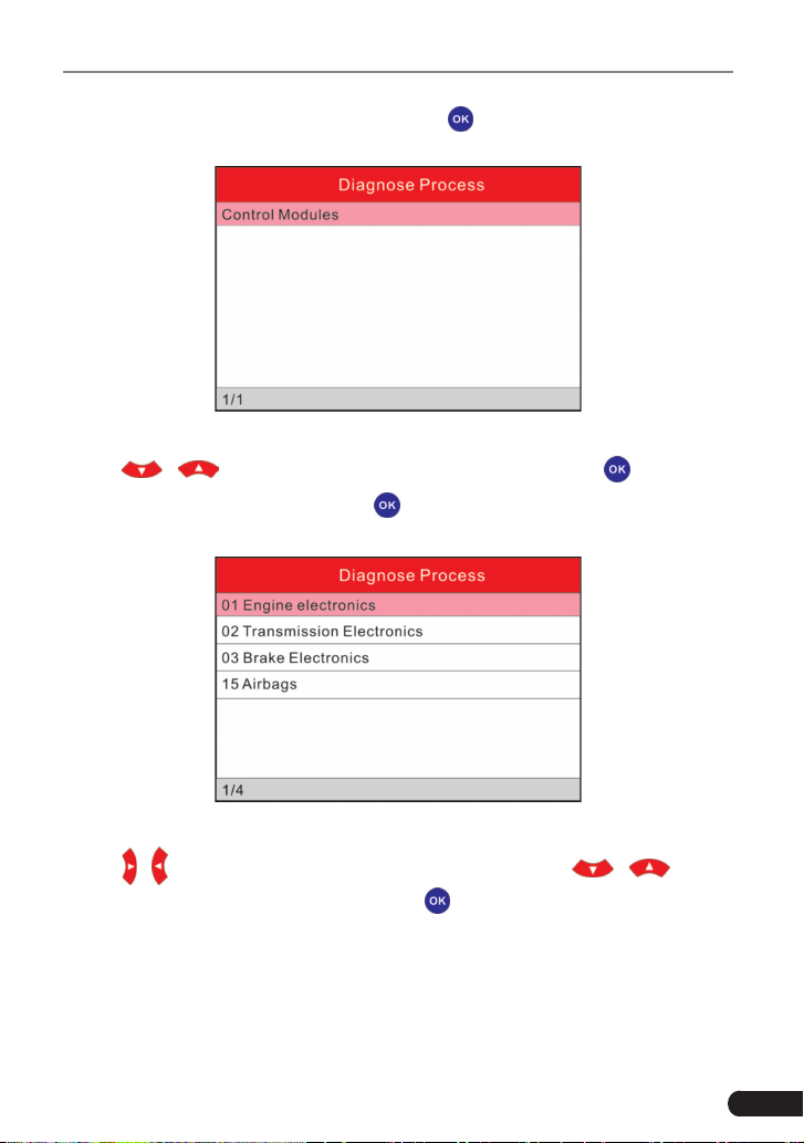
Take VW for example. Select [VW] and press [
], the screen will display as Fig.
5-30.
Figure 5-30
Press [
]/[ ] button to select the desired item, then press [ ] button.
Choose [Manually Select] and press [
] button, the screen will display as gure
5-31:
Figure 5-31
Press [
]/[ ] button to turn to next or previous page. Press [ ]/[ ] button
to select the desired items, then press [
] button, the screen will display
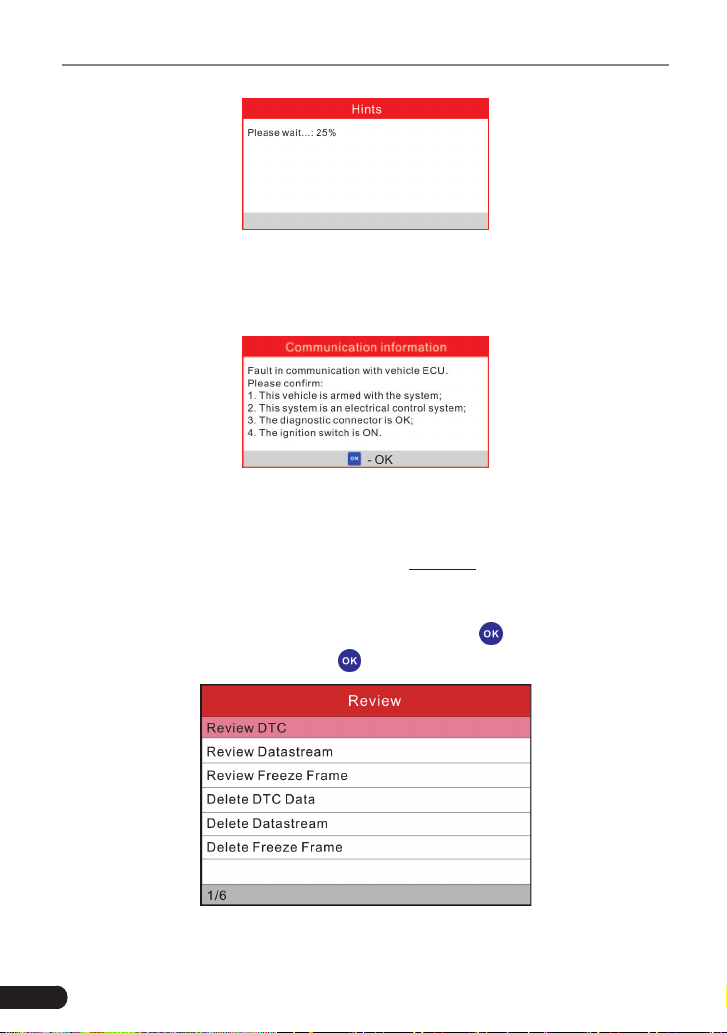
communication process, as indicated in gure 5-32:
24
LAUNCH Creader Professional CRP123 User's Manual
Figure 5-32
After communication is complete, the system will start diagnosing the selected
item. If communication failed, a dialog box prompting you communication failure
will appear as shown on Fig. 5-33.
Figure 5-33
5.3 Review
This function is used to review or delete the recorded DTC, Data Streams and
Freeze Frame. For details on how to record, please refer to “Chapter 6.4 Record
Mode”.
Select “Review” on Diagnose menu screen and press [
] to enter Figure 5-34.
Select the desired option and press [
] to perform the corresponding function.
Figure 5-34
25
LAUNCH Creader Professional CRP123 User's Manual
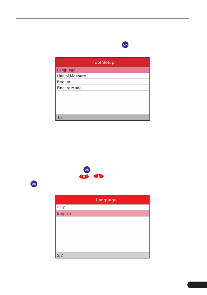
6 Settings
Select [Settings] in the main menu and press [
], the system will enter the
following screen:
Figure 6-1
6.1 Language
This option enables you to set the user interface language.
Due to continuous software upgrade, language interface may differ from different
software versions (Figure 6-2 is provided for reference and demo purpose).
Choose [Language] and press [
] to conrm, the screen will enter the language
selection interface. Use the [
]/[ ] button to choose the desired one and
press [
] to save your change.
Figure 6-2
26
LAUNCH Creader Professional CRP123 User's Manual
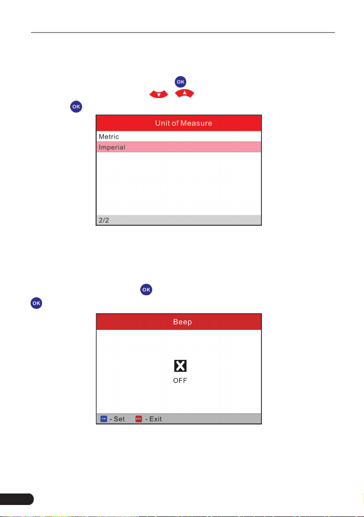
6.2 Unit of Measure
This option allows you to set measurement unit.
Choose [Unit of Measure] and press [
] to conrm, the screen will enter the
unit setting interface. Use the [
]/[ ] button to choose the desired one
and press [
] to save your change.
Figure 6-3
6.3 Beeper
It is used to set On/Off the buzzer.
Choose [Beeper] and press [
] to conrm, the screen enters Fig. 6-4. Press
[
] to switch between on and off.
Figure 6-4
6.4 Record Mode
It is used to turn On/Off recording function.

27
LAUNCH Creader Professional CRP123 User's Manual
Choose [Record Mode] and press [
] to conrm, the screen enters Fig. 6-5.
Press [
] to switch between on and off. When recording is ON, the icon
appears, then CRP123 can record DTC’s, record Data Stream and Freeze
Frames.
Figure 6-5
28
LAUNCH Creader Professional CRP123 User's Manual
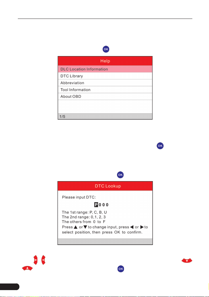
7. Help
This menu enables you to view device information and OBD introduction.
In main menu, select [Help] and press [
] to enter Figure 7-1.
Figure 7-1
7.1 DLC Location Information
In Figure 7-1, select [DLC Location Information] and press [ ] to view the
location of vehicle’s DLC.
7.2 DTC Library
In Figure 7-1, select [DTC Library] and press [
] to enter the following screen.
Figure 7-2
Press [
]/[ ] button to move the highlight bar to different position. Press [
]/[ ] button to alter the value, then press [ ] button, the screen will display
29
LAUNCH Creader Professional CRP123 User's Manual
denition of the DTC, as indicated in gure 7-3:
Figure 7-3
Press [
] to return to the previous screen.
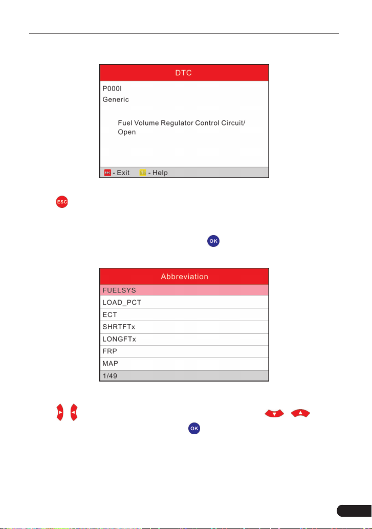
7.3 Abbreviation
In Figure 7-1, select [Abbreviation] and press [
] to enter the abbreviation word
list.
Figure 7-4
Press [
]/[ ] button to turn to next or previous page. Press [ ]/[ ] button
to highlight different items, then press [
] button, the screen will display as
shown on Figure 7-5
.

30
LAUNCH Creader Professional CRP123 User's Manual
Figure 7-5
Press [
] to return to the previous screen.
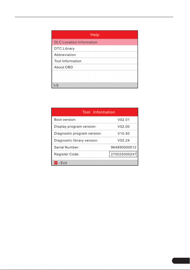
7.4 Tool Information
In Figure 7-1, select [Tool Information] and press [ ] to view the related
information of CRP123.
Figure 7-6
Note: You are strongly recommended to note down the Serial Number and
Register Code in Figure 7-6 since these 2 pieces of information are required
while registering your CRP123.
Press [
] to return to the previous screen.
7.5 About OBD
This option allows you to have a general knowledge of OBD.
31
LAUNCH Creader Professional CRP123 User's Manual
8. Register & Update
Hardware Requirement:
1. A computer that can access the Internet.
2. A TF card reader/writer and a TF card that need to be updated.
Follow the steps described as below to proceed registration and update:
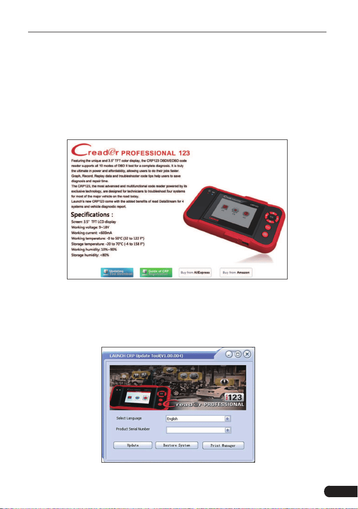
1. Go to http://www.x431.com/CRP123 and click update icon.
Figure 8-1
2. Download and install the CRP123 update tool and launch the program when
installed.
3. You will be prompted to type in the Serial Number (located on the back of the
tool).
Figure 8-2

32
LAUNCH Creader Professional CRP123 User's Manual
4. After the Serial Number is entered, click update and enter the following
information. Click “Submit.”
Figure 8-3
(If you need the Register Code, proceed to the steps 5-8.)
(If you have the Register Code, proceed to step 9 directly.)
5. The Register Code can be found by connecting the supplied USB cord to the
CRP123 and inserted into the computer.
6. When the tool has powered up, place cursor on the Help icon and press the
OK button.
Figure 8-4
7. Select Tool Information, press OK.
33
LAUNCH Creader Professional CRP123 User's Manual
Figure 8-5
8. This is the Register Code number for inputting into step 4.
Figure 8-6
(Return to step 4 and input the code and then proceed)
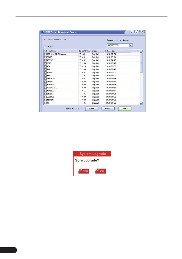
9. Install the TF card from the tool into the supplied TF card adapter and insert
into USB port of PC.
10.Reopen the CRP update Suite and select the updates you would like to
preform or click “Select All” and click “Download”.
34
LAUNCH Creader Professional CRP123 User's Manual
Figure 8-7
11. Once all steps are complete, reinsert the TF card into the tool and power the
tool via USB in computer or via OBD2 port in vehicle. The tool will prompt
you to upgrade, click “OK” to start updating and a progress bar will appear. It
may takes several minitues to nish update if your upgrade package le is too
large, please wait.
Figure 8-8
12.The registration process is now complete!

35
LAUNCH Creader Professional CRP123 User's Manual
9. FAQ
Here we list some frequently asked questions and answers relating to CRP123.
Question: System halts when reading data stream. What is the reason?
Answer: It may be caused by a slackened connector. Please turn off the
CRP123, rmly connect the connector, and switch on it again.
Question: Screen of main unit ashes at engine ignition start.
Answer: Caused by electromagnetic disturbing, and this is normal phenomenon.
Question: There is no response when communicating with on-board computer.
Answer: Please confirm the proper voltage of power supply and check if the
throttle has been closed, the transmission is in the neutral position, and the
water is in proper temperature.
Question: Why are there so many fault codes?
Answer: Usually, it’s caused by poor connection or fault circuit grounding.

36
LAUNCH Creader Professional CRP123 User's Manual
Warranty
THIS WARRANTY IS EXPRESSLY LIMITED TO PERSONS WHO PURCHASE
LAUNCH PRODUCTS FOR PURPOSES OF RESALE OR USE IN THE
ORDINARY COURSE OF THE BUYER’S BUSINESS.
LAUNCH electronic product is warranted against defects in materials and
workmanship for one year (12 months) from date of delivery to the user.
This warranty does not cover any part that has been abused, altered, used for a
purpose other than for which it was intended, or used in a manner inconsistent
with instructions regarding use. The exclusive remedy for any automotive meter
found to be defective is repair or replacement, and LAUNCH shall not be liable
for any consequential or incidental damages.
Final determination of defects shall be made by LAUNCH in accordance with
procedures established by LAUNCH. No agent, employee, or representative of
LAUNCH has any authority to bind LAUNCH to any afrmation, representation,
or warranty concerning LAUNCH automotive meters, except as stated herein.
Order Information
Replaceable and optional parts can be ordered directly from your LAUNCH
authorized tool supplier. Your order should include the following information:
1. Quantity
2. Part number
3. Item description
Customer Service
If you have any questions on the operation of the unit, please contact local
dealer, or contact LAUNCH TECH. CO., LTD:
Tel: 86-755-84528767
E-mail: [email protected]

Statement: LAUNCH reserves the rights to make any change to product designs
and specications without notice. The actual object may differ a little from the
descriptions in the manual in physical appearance, color and configuration.
We have tried our best to make the descriptions and illustrations in the manual
as accurate as possible, and defects are inevitable, if you have any question,
please contact local dealer or after-sale service center of LAUNCH, LAUNCH
does not bear any responsibility arising from misunderstandings.