Loading ...
Loading ...
Loading ...

5
5.0 Setup and assembly
Read and understand all
assembly instructions before attempting
assembly. Failure to comply may cause serious
injury.
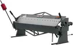
5.1 Shipping contents
Refer to Figure 1.
1 Box and pan brake
1 Counterweight – A
1 Counterweight rod – B
2 Pipe handles – C
1 Stop rod with cotter pin – D
1 Stop collar – E
Figure 1
5.2 Tools required for assembly
Set of metric hex wrenches
pliers
5.3 Unpacking and cleanup
1. Remove all contents from shipping crate and
compare to the contents list in this manual. If
shipping damage or any part shortages are
identified, contact your distributor. Do not
discard packing material until brake is
assembled and operating satisfactorily.
2. Carefully clean all rust protected surfaces with
a mild solvent or kerosene and a soft rag. Do
not use lacquer thinner, paint thinner, or
gasoline – these will damage painted surfaces.
3. Coat all machined surfaces with a light coat of
oil to inhibit rust.
5.4 Assembly
Refer to exploded view if additional clarification is
needed for assembly.
1. Remove all crating from around machine, and
remove bolts holding brake to pallet.
2. Use hoist or forklift to carefully move brake to a
dry, well-lighted area on a sturdy bench or
stand. Use appropriate fasteners (not included)
to secure brake to stand. Machine location must
allow room for loading and offloading stock, and
access on all sides for maintenance.
Do not allow anyone
beneath the brake while moving it into
position and until it is secured on bench or
stand.
NOTE: An optional JET stand (p/n 754200) is
designed for the brake, and is available by
calling customer service or visiting our website,
www.jettools.com
3. Verify that brake is level; use shims if
necessary.
4. Install counterweight rod (B, Figure 2) into left
hinge, and tighten set screws (B
1
). Slide
counterweight (A) onto rod and tighten screw
(A
1
).
Figure 2
5. Install stop rod (D) through hole in weldment, as
shown in Figure 3. Insert cotter pin (D
1
) at end
of rod, and bend the ends to secure. Install stop
collar (E) at opposite end and tighten set screw.
Figure 3
The pipe handles (C, Figure 1) can be installed onto
the apron handles for extended leverage, if desired.
Loading ...
Loading ...
Loading ...