
ANCEL
Version:V1.00.002
Statement: ANCEL owns the complete intellectual property rights for the software used by
this product. For any reverse engineering or cracking actions against the software, ANCEL
will block the use of this product and reserve the right to pursue their legal liabilities.

ANCEL
www.anceltech.com
IC Requirement
This device contains licence-exempt transmitter(s)/receiver(s) that comply with Innovation, Science and
Economic Development Canada's licence-exempt RSS(s). Operation is subject to the following two
conditions:
(1)This device may not cause interference.
(2)This device must accept any interference,including interference that may cause undesired operation
of the device.
L'emetteur/recepteur exempt de licence contenu dans le present appareil est conforme aux CNR
d'Innovation,Sciences et Developpement économique Canada applicables aux appareils radio exempts
de licence. L'exploitation est autorisée aux deux conditions suivantes:
1)L'appareil ne doit pas produire de brouillage;
2)L'appareil doit accepter tout brouillage radioelectrique subi, meme si le brouillage est susceptible d'en
compromettre le fonctionnement.
IC WARNING
Cet equipement est conforme aux limites d'exposition aux rayonnements ISED etablies pour un
environnement non controle. Lutilisateur final doit suivre les instructions specifiques pour satisfaire les
normes. Cet émetteur ne doit pas etre co-implanté ou fonctionner en conjonction avec toute autre antenne
ou transmetteur.
Le dispositif portatif est concu pour repondre aux exigences d'exposition aux ondes radio etablie par
ledeveloppement énergetique DURABLE. Ces exigences un SAR limite de 1,6 W/kg en moyenne pour
un gramme de tissu. La valeur SAR la 0.733W/kg plus elevee signalee en vertu de cette norme lors de la
certification de produit à utiliser lorsqu'll est correctement porte sur le corps.

www.anceltech.com
ANCEL
FCC Requirement
Changes or modifications not expressly approved by the party responsible for compliance could void the
user's authority to operate the equipment.
Th is de vi ce co mp li es wit h Pa rt 15 of th e FC C Ru le s . Op er at io n is subjec t to th e foll ow ing two cond iti ons:
(1 ) th is de vi ce ma y no t ca us e har mf u l int erf ere n ce, and
(2) this device must accept any interference received, including interference that may cause undesired
operation.
Note: This equipment has been tested and found to comply with the limits for a Class B digital device,
pursuant to Part 15 of the FCC Rules. These limits are designed to provide reasonable protection
ag ains t harmf ul inter fer e nce in a res iden tial ins tall ati o n . Th is equ i pme n t gen e rat es, use s, and can
radiate radio frequency energy, and if not installed and used in accordance with the instructions, may
cause harmful interference to radio communications. However, there is no guarantee that interference
will not occur in a particular installation. If this equipment does cause harmful interference to radio
or tel ev is io n rec ep ti on , wh ic h ca n be det er min ed by tu rn i ng th e eq ui pm en t off and on , the us e r is
encouraged to try to correct the interference by one or more of the following measures:
-Reorient or relocate the receiving antenna.
-Increase the separation between the equipment and receiver.
-Connect the equipment into an outlet on a circuit different from that to which the receiver is connected.
-Consut the dealer or an experienced radio/TV technician for help.
FCC WARNING
This equipment complies with FCC radiation exposure limits set forth for an uncontrolled environment. End
user must follow the specific operating instructions for satisfying RF exposure compliance. This transmitter
must not be co-located or operating in conjunction with any other antenna or transmitter.
The mobile device is designed to meet the requirements for exposure to radio waves established by the
Federal Communications Commission (USA). These requirements set a SAR limit of 1.6 W/kg averaged
over one gram of tissue. The highest SAR value reported under this standard during product certification
for use when properly worn on the body is 0.733 W/kg.
For body operation, this device has been tested and meets FCC RF exposure guidelines when used with
any accessory that contains no metal and that positions a minimum of 15mm from the body. Use of other
accessories may not ensure compliance with FCC RF exposure guidelines.

ANCEL
www.anceltech.com
Copyright Information
Copyright ◎20 21 by OBDSPACE TECH CO., LTD(hereinafter referred to as "ANCEL"). All rights reserved.
No pa rt of thi s pu bl ic at io n may be re pr o d uc ed , sto re d in a re t ri ev al sys te m , or tran smit ted in any form or
by an y mea ns , el ec tr on ic , mec h an ic al , ph ot oc op yi ng an d rec o rd in g or other wis e , wit hout the prio r wr itt e n
pe rmis sion of ANC EL . The info rmat ion co ntai ned herei n is des igne d only fo r the us e of this un it . AN CEL is
not respon si ble for any use of this info rmation as applied to other units.
Neither ANCEL nor its affiliates shall be liable to the purchaser of this unit or third parties for damages,
losses, costs, or expenses incurred by purchaser or third parties as a result of: Accident, misuse, or abuse
of this unit, or unauthorized modifications, repairs, or alterations to this unit, or failure to strictly comply with
ANCEL operating and maintenance instructions. ANCEL shall not be liable for any damages or problems
arising from the use of any options or any consumable products other than those designated as Original
ANCEL Products or ANCEL Approved Products.
Formal statement: The names of other products mentioned in this manual are intended to explain how to
use this equipment, and the registered trademark ownership still belongs to the original company.
This equipment is designed for professional technicians or maintenance personnel.
Trademark
ANCEL is a registered trademark of OBDSPACE TECH CO., LTD in China and other overseas countries.
Al l ot h e r AN C E L tr a d e m a r k s , s e r v i c e ma rk s , do m a in na m e s , l og o s , an d co m p an y n am e s re f e rr e d to in
th is ma nu al are eit he r tr ad ema rk s , reg is te re d tra de mar ks, ser vice mar k s, do main name s, logos , comp any
na m es o f or ar e ot h er w i s e t he pr op e r t y o f AN C E L or it s af fl ia t e s . In co u n t ri e s wh e re an y of th e AN C EL
tr ad em a rks , se rv ic e mar ks , do ma in nam es, lo g o s and com pa ny nam es are not reg ist ere d, AN C EL
cl ai m s ot h e r ri gh t s a ss o c i a te d wi t h unr eg ist e r ed tr ad e ma r k s, se r v ic e ma r k s, do ma i n na me s , lo g os , and
co mp an y na me s . Ot he r pro d uct s or co mp an y na me s r ef erre d to in this ma nu a l ma y be trade mark s of thei r
re sp ec tiv e ow ner s . You may no t us e an y tra de ma rk , ser vi ce mar k , dom ai n nam e , log o , or com pa ny na me
of AN C E L DS or any th ir d p ar t y wi t h o ut pe r m i s si o n fr om th e ow n e r of th e app l ic a bl e tr ad e ma r k, ser v ic e
ma rk, doma in na me, logo , or co mpany nam e.
You may contact ANCEL TECH INC by visiting the website at www.anceltech.com, or writing to
OBDSPACE TECH CO., LTD., Address:D03,Block A, No. 973 Minzhi Ave, Longhua District,Shenzhen, Gu
angdong,China, to request written permission to use Materials on this manual for purposes or for all other
questions relating to this manual.
Safety Precautions and Warnings
To avoid personal injury, property loss, or accidental damage to the product, read all of the information in
this section before using the product.
Handle equipment carefully
Do not drop, bend, or puncture the tool, or insert extra objects into or place heavy objects on
the device. The vulnerable components inside may be damaged.
Do not disassemble or modify the equipment
The device is a sealed device with no user-serviceable parts inside. All internal repairs must be performed

www.anceltech.com
ANCEL
by an authorized maintenance organization or qualified technician. Attempts to disassemble or modify the
device will void the warranty.
Do not try to replace the internal battery
The internal rechargeable lithium battery must be replaced by an authorized maintenance organization or
qualified technician. Contact the dealer for factory replacement.
Adapter information
Avoid immersing the device in water or placing it in a location where it may absorb moisture or other liquids.
During normal use, the charging device may become hot. Please ensure that there is good ventilation
while charging device.
f any of the following situation occurs, please unplug the charging device:
· The charging device is exposed to rain, liquid or in an environment with excessive overlap.
· The charging device showed physical damage.
· Cleaning the charging device.
Data and Software Protection
Do not delete unknown files or change the names of files or directories created by others, otherwise the
device software may not run.
Note: Access to network resources makes the device vulnerable to computer viruses, hackers, spyware, and
other malicious behaviors, and may damage the device, software, or data. To make ensure that you are using
firewalls, anti-virus software and anti-spyware software to provide adequate protection for your computer and
keep these software up to date.
Precautions on Using this tool
· To make sure the ignition switch should be in the OFF position when plugging and unplugging the
·
·
t
g
h
n
e stor
ostic
age
con
b
n
o
e
x
c
on
tor
t
t
h
o
e
p
bac
op
k
u
o
p
f
t
th
h
e ma
e dia
in
g
n
u
o
ni
s
t
t
,
i
wh
c c
e
o
n
n
th
ne
e
c
t
v
o
e
r
h
ic
D
le
o
d
n
ia
ot
g
n
p
os
ull
i
s
o
i
r
s
u
fi
s
nish
e s
e
h
d
a
.
rp
objects to pry the diagnostic connector.
Precautions on Operating Vehicle's ECU
· Do not disconnect battery or any wiring cables in the vehicle when the ignition switch is on, as this could
avoid damage to the sensors or the ECU.
· Do not place any magnetic objects near the ECU. Disconnect the power supply to the ECU before
performing any welding operations on the vehicle.
· Use extreme caution when performing any operations near the ECU or sensors. Ground yourself when
you disassemble PROM, otherwise ECU and sensors can be damaged by static electricity.
· When reconnecting the ECU harness connector, be sure it is attached firmly, otherwise electronic
elements, such as ICs inside the ECU, can be damaged.

ANCEL www.anceltech.com
Content
1.Quick Start Manual
...............................................................................................................
1
1.1 Initial Use
..........................................................................................................................................
1
1.1.1 Turn on the Machine
................................................................................................................
1
1.1.2 Language Setting
.............................................................................................................
1
1.1.3 Connect Wi-Fi
...........................................................................................................................
1
1.1.4 Choose Time Zone
...................................................................................................................
2
1.1.5 UserAgreement
.......................................................................................................................
2
1.1.6 Create an Account
.............................................................................................................
2
1.1.7 VCIActivation
..............................................................................................................................
1.2 Diagnosis Flowchart
.........................................................................................................................
3
1.3 Function Menu
..................................................................................................................................
4
1.4 Charging
............................................................................................................................................
5
1.5 Battery
......................................................................................................................................
5
1.6 VCl Connections
................................................................................................................................
5
1.7 Printer Installation
..............................................................................................................................
6
2. Introduction
............................................................................................................................
6
2.1 Product Profile
..................................................................................................................................
6
2.2 Components&Controls
...................................................................................................................
7
2.3 Function Modules
......................................................................................................................
8
2.4Parameters
.....................................................................................................................................
10
3. Begin to Use
...............................................................................................................................
10
3.1 Intelligent Diagnosis
................................................................................................................
10
3.2 Local Diagnosis
.............................................................................................................................
10
3.2.1 Manual Diagnosis
..................................................................................................................
11
3.2.2 System Selection
...................................................................................................................
13
3.2.3 Function Selection
..........................................................................................................
13
3.3 Quick Check and Printing
........................................................................................................
17
3.4 Maintenance
...........................................................................................................................
18
3.4.1 Oil Reset
................................................................................................................................
18
3.4.2 Elec. Throttle Adaption
...........................................................................................................
18
3.4.3 Steering Angle Reset
.............................................................................................................
19
3.4.4 Battery Matching
....................................................................................................................
19
3.4.5ABS Bleeding
.................................................................................................................
19
3.4.6 Break-pad Reset
...................................................................................................................
19
3.4.7 DPF Regeneration
.................................................................................................................
20
3.4.8 Gear Learning
........................................................................................................................
20
3.4.9 IMMO Service
.........................................................................................................................
20
3.4.10 Injector Coding
....................................................................................................................
20
3.4.11 TPMS Reset
..................................................................................................................
20
3.4.12 Suspension Matching
.........................................................................................................
21
3.4.13 AFS Reset
............................................................................................................................
21

www.anceltech.com
ANCEL
3.4.14 A/T Learning
................................................................................................................
21
3.4.15 Sunroof Initialization
.............................................................................................................
21
3.4.16 EGR Adaption
.....................................................................................................................
21
3.4.17 ODO Reset
..........................................................................................................................
21
3.4.18 Airbag Reset
........................................................................................................................
21
3.4.19 Transport Mode
....................................................................................................................
21
3.4.20A/F Reset
...................................................................................................................................
22
3.4.21 Stop/Start Reset
........................................................................................................................
22
3.4.22 NOx Sensor Reset
........................................................................................................
22
3.4.23 AdBlue Reset (Diesel Engine Exhaust Gas Filter)
...........................................................
22
3.4.24 Seat Calibration
...................................................................................................................
22
3.4.25 Coolant Bleeding
.................................................................................................................
22
3.4.26 Tyre Reset
..........................................................................................................................
22
3.4.27 Windows Calibration
.......................................................................................................
2
3.4.28 Language Change
.......................................................................................................
22
3.5 TPMS Diagnostics
.........................................................................................................................
23
3.6 Diagnostic Feedback
.....................................................................................................................
24
3.7 Repair Info
......................................................................................................................................
25
3.7.1 Fault Code Enquiry
........................................................................................................
25
3.7.2 Vehicle Coverage Enquiry
.........................................................................................................
25
3.7.3 Learning Course
.........................................................................................................................
25
3.8 ANCELFile
......................................................................................................................................
25
3.9 ANCELStore
...................................................................................................................................
25
4.Software Update
.........................................................................................................................
26
4.1 Upgrade all Software
....................................................................................................................
26
5.Set Up
...................................................................................................................................
27
5.1VC
.................................................................................................................................................
27
5.2 Activate VC
....................................................................................................................................
27
5.3 Fix VCl firmware/system
.................................................................................................................
27
5.4 Data Stream Sample
...............................................................................................................
27
5.5 My Order
...............................................................................................................................
27
5.6 Profile
.............................................................................................................................................
27
5.7 Change Password
........................................................................................................................
27
5.8 Wi-Fi Settings
.................................................................................................................................
27
5.9 Diagnostic Software Clear
..............................................................................................................
27
5.10 Business Information
.............................................................................................................
28
5.11 Customer Management
.........................................................................................................
28
5.12 Photo Album
.................................................................................................................................
28
5.13 Screen Recorder
..........................................................................................................................
28
5.14 Settings
...............................................................................................................................
28
5.15 Hotkey Setting
.....................................................................................................................
28
6.FAQ
........................................................................................................................................
28

ANCEL
www.anceltech.com
1. Quick Start Manual
1.1 Initial Use
The following settings should be made when you initially use the tool.
1.1.1 Turn on the Machine
After pressing the power button, images will be shown on the screen as follows.
CEL
1.1.2 Language Setting
Select the tool language from the languages displayed on the interface.
English
Pehh
tp
Fnpia
niims
1.1.3 Connect Wi-Fi
The system will automatically search all available Wi-Fi networks and you can choose the Wi-Fi needed. If
the chosen network is open, you can connect it directly; If the chosen network is encrypted, you must enter
the corect password. Then You can connect Wi-Fi after clicking "connect".
Tips: Wi-Fi must be set. Ifno Wi-Fi network is available nearby, you can enable "Portable Mobile Hotspot".

www.anceltech.com
ANCEL
m
Fan-
tihm
1.1.4 Choose Time Zone
Choose the time zone of the current location, then the system will automatically cofigure the time according
to the time zone you chose.
Amrica/Lsa_Angeles
☑
Ara/T
aphe
niaciiaik
a
1.1.5 User Agreement
Please read all the terms and conditions of the user agreement carefully. Choose "Agree all the above
terms", and click the "Agree" button to complete the registration process.
Then the page will jump to the "Congratulations on your successful registration" interface.
1.1.6 Create an Account
You need to register an account through your e-mail box. If you have owned other products of ANCEL
series, you can directly log in by using the account available.

ANCEL
www.anceltech.com
1.1.7 VCI Activation
Enter the connector serial number and activation code to activate and bind the diagnostic connector. If you
have not activated it, you can also click "Settings" on the main interface to enter and select "Activate" to
operate.
! Tips: The activation code is an 8-digit number and is pasted on the "password letter".
1.2 Diagnosis Flowchart
Register / Create an Account
BT Connection
Log in
Choose Vehicle Type
Activation
Choose System
Connect Diagnostic Connector
www.anceltech.com
ANCEL
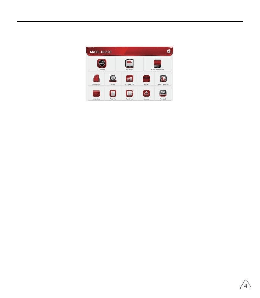
1.3 Function Menu
Power on the main units, the system will automatically enter into the function menu selection interface:
It mainly includes the following features:
· The main unit and diagnostic co nnector support Blue tooth and wired communication. Wired
communication is superior to Bluetooth connection in terms of transmission rate and anti-interference.
· Supports powerful inteligent VIN recognition technology, which is convenient, fast and efficient.
· Qu ick Check Print in g: Automati c ld en tificat io n of Ve hi cle Informat io n, Auto Check an d Rep or t Print in g.
· Modular expansion: Support 8 optional modules: printer, work light, videoscope, battery tester, scope
box, thermal imager, moudledock, wireless TPMS tool.
It can detect faults in the electronic control systems of most high-, medium-, and low-end vehicles in
Asia, Europe, the United States and China. Powerful diagnostic functions include reading fault codes,
clearing fault codes, reading data streams, action tests, and special functions.
Maintenance function: matching, coding, programming of most vehicles' programable modules, and most
commonly used maintenance and reset functions: Oil Reset, Elec. Throttle Adaption, IMMO Service,
Injector Coding, Break-pad Reset, Steering Angle Reset, ABS Bleeding, AFS Reset, Battery Matching,
A/T Learning, DPF Regeneration, EGR Adaption, TPMS Reset, Sunroof Initialization, Suspension
Matching, Gear Learning, Airbag Reset, ODO Meter Reset, AdBlue Reset, A/F Reset, Coolant Bleeding,
Language Change, NOx Sensor Reset, Seat Calibration, Stop/Start Reset, Transport Mode, Tyre Reset,
Windows Calibration.
TPMS function: with wireless TPMS tool (optional), TPMS activation, programming and learning
functions can be supported.
· Onli ne one clic k to upd ate di agno s is s oftwa re, cli ent an d fir mware.
· Feedback: Any abnormal of software or function during the diagnosis, just feedback to us, our
professional technician will track and deal with it in time.

www.anceltech.com
ANCEL
1.4 Charging
Follow the steps below to charge the main unit:
· Connect one end of the power cord to the USB socket of the power adapter.
· Connect the other end to the charging jack on the bottom of the main unit.
· Plug the charger power plug into a power outlet to start charging.
· When the battery status icon displays , the main unit has been charged.
When it displays , the charging process has been completed and you shall disconnect the main unit.
1.5 Battery
· It is normal that the main unit won't tum on when charging because the battery has not been used for a
long time or it is exhausted. Please turn on the main unit again after charging the battery for a while.
· Please charge the main unit through the charger in the package. The company assumes no responsibility
for damages and losses caused by charging with chargers other than those specified by the company.
· The battery can be recharged repeatedly. However, as the battery is wearable, the standby time of the
device will be shortened after long-time use. Please avoid frequent repeated charging so as to extend
battery life
· The battery charging ti me varies with temperature and battery status.
· When the battery power is low, the system will pop up a prompt reminding you to connect the charger.
When the battery power is too low, the device will turn off.
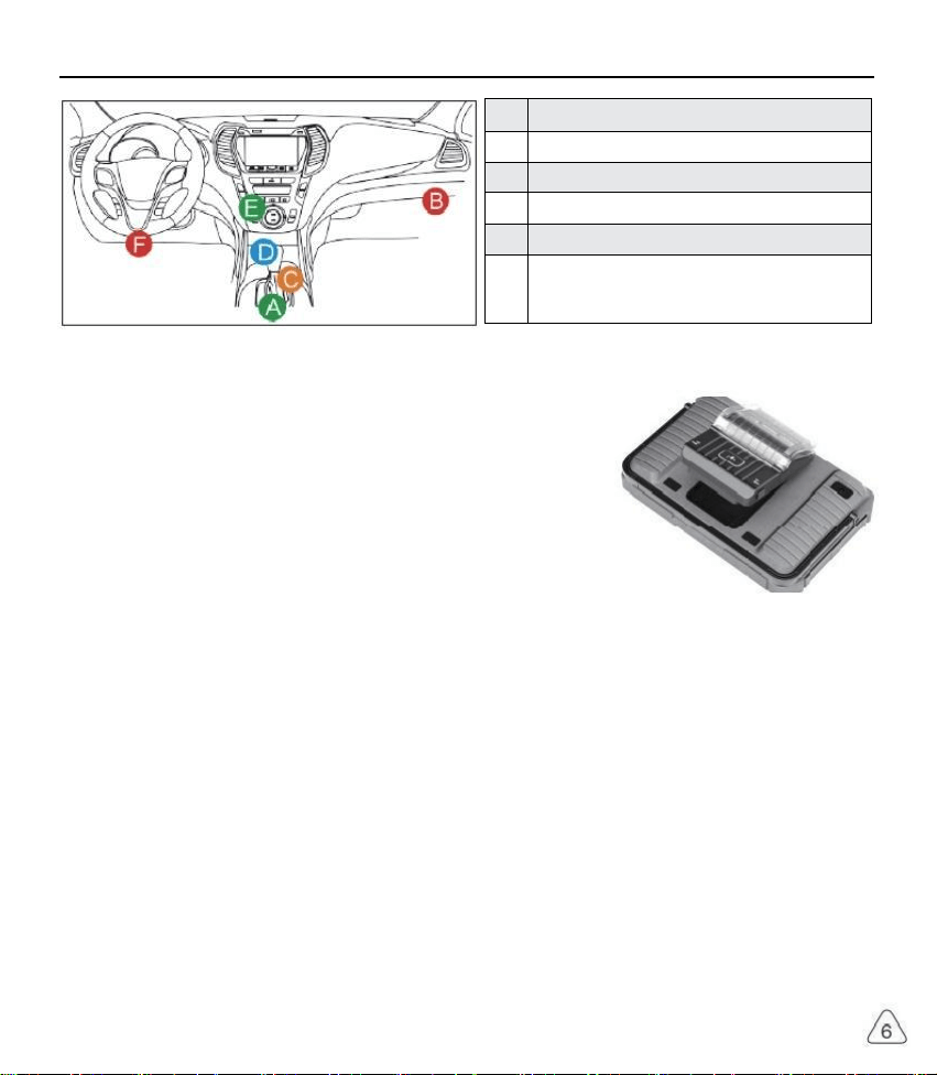
1.6 VCI Connections
Connection steps as below:
(1) Locate vehicle's DLC socket. Most of the DLC are standard OBD ll diagnostic sockets (non-standard
OBD ll vehicle diagnostic sockets need to use the corresponding adapter).The DLC is usually located
12 inches from the center of the instrument panel (dash), under or around the driver's side for most
vehicles. If the DLC cannot be found, refer to the vehicle's service manual for the location.
(2) For OBDlI vehicle, follow the steps mentioned below to proceed:
a) Plug the VCl dongle into the vehicle's DLC socket
b) Use the OBD ll extension cable to connect the VCl dongle and DLC socket.
(3) For non-OBDll vehicle, If the pin of the DLC is damaged or has insufficient power, please follow the
either of the following methods to proceed:
a) Cigarette Lighter cable
b)Battery Clamps Cable
www.anceltech.com
ANCEL
A
Opel, Volkswagen, Aud
B
Honda
C
Volkswagen
D
Opel, Volkswagen, Citroen
E
Changan
F
Hyundai, Daewoo, Kia, Honda, Toyota, Nissan,Mitsubishi
Renault, Opel, BMW, Mercedes-Benz, Mazda, Volkswagen
Audi, GM, Chrysler,Peugeot, Regal, Beijing Jeep, Citroen and
most prevailing models
1.7 Printer Installation (Optional)
The printer is installed on the back of the main unit. Please follow the
steps below:
(1) Unscrew the backplane screws and remove the host backplane.
(2) Insert the ma in unit card slot into one side of the printer.
(3) Press the buck le on the side of th e printer to snap on it into the host.
(4) When the main unit is on, it will automatically identify and connect
the printer.
2. Introduction
2.1 Product Profile
ANCEL DS, based on the Android 10 System, is a new generation of modular high-end intelligent
di ag no st ic eq ui p me nt de ve lo pe d by ANC E L.
ANCEL DS adopt a unique modular design to meet various applicatio n scenarios, including diagnostic
module, printer, videoscope, work light, thermal imager, scope box, moduledock and TPMS tool.

ANCEL
www.anceltech.com
2.2 Components & Controls
(1) Display
(2) Power Key
Pre ss and hold it for 3 seconds to turn it off.
Press and hold it for 8 seconds to perform forced shutdown.
Press it on ce to activate or tur n off the device.
(3)
Ty p e C Ch a r gi n g Sl ot : co n ne ct th e sup p li ed ch ar g er fo r ch ar gin g
(4 ) USB Port: Reserved for add- on modules and other devices with similar port.
(5) Rear Camera
(6) Speaker
(7) Backplane: Remove the backplane of the tablet , and install function modules on the backend.
(8) Pin : Used for co mm unic atio n bet ween th e fu nction ex pansion mo dule and the host .
(9)Adjustable Kickstand: Flip out it to 180-degree angle and work comfortable at your desk, or hang it
on automotive part.
(1 0 ) Rubber Protection Sheet

www.anceltech.com
ANCEL
2.3 Function Modules
ANCEL TOOL support below optional function modules, list as below:
S/N
Name
Image
Description
1
ANCEL
PRINTER
Thermal printer, work with the main unit, also can work
with moduledock. Quick print diagnostic reports anytime
and anywhere.
2
ANCEL
WORKLIGHT
High Brightness Work light, ultra-high 25000K white-light
with 144 high brightness LED lights
Service life is more than 10,000 hours. It works with the
main unit or use independently with the dock.
Application scenarios: 1.Go out to rescue at night; 2.Car
eparing in dark environment
3
ANCEL Video
Scope
Super long custom coil pipeline design, flexible bending
with durable materials, suitable for a variety of complex
environments. Multiple uses with 3 kinds of special
connectors(Hook, side view mirror, magnet). Supports
720P HD image. With 6 auxiliary lights for brighter light,
easily used in dark environment.
Application scenarios: 1. Engine combustion chamber
inspection; 2. Engine internal carbon deposit inspection;
3. Three-way catalytic inspection; 4.Air-conditioning
pipeline inspection; 5. The corners of the vehicle that
are not easy to detect, such as falling screws, or water
leakage, cracks, and foreign objects...
4
ANCEL
MODULEDOCK
Designed for the printer, work light and other modules to
use independently for different work scenarios. The dock
is equipped with a universal tripod connection for easy
fixation. The 900mAh extra-large capacity battery can
meet the requirements of long-term use and display the
remaining power in real time.

ANCEL
www.anceltech.com
5
ANCEL
Therma
Imager
320*240 ultra-high pixel with its own thermal tracking
point, which can be used for image superposition (refers
to the coincidence of real image and thermal image
collected by the camera, so as to achieve more accurate
positioning). The thermal sensitivity reaches 0.07 ℃
(32.126 °F), which is more accurate.
Higher image acquisition resolution is displayed on the
high-definition display. ANCEL Thermal lmager has a
arge number of car diagnostic fault thermal comparison
maps. Technicians can accurately locate car problems by
image comparison.
Application scenarios: 1. Cylinder misfire; 2.Generator
power generation; 3. Belt and bearing aging; 4.Relay
overload; 5. Three-way catalytic blockage, etc.
6
ANCEL Scope
Box
Equipped with 4 channels 100MHz bandwidth, sampling
rate reaches up to 1GS/ s. Combined with the ANCEL
screen to achieve full touch control operation. Specially
developed auto repair and detection special menu and
HD waveform display brings more convenient for usage
Application scenarios: The ANCEL Scopebox can
accurately determine the problems of sensors, actuators
control modules or lines
7
ANCEL
Battery Tester
Detect the battery voltage, resistance service life current
and other battery information.
Integrated with ANCEL high-resolution screen and
high-precision data monitoring to make the detection
efficiency greatly improved.
Application scenarios: detection of car battery health,
starting system and charging system.
8
Wireless
TPMS G1
Work with ANCEL to complete tire pressure diagnosis
elated functions.
Application scenarios: 1. Read tire pressure information
such as pressure, temperature, and battery status; 2
Change the sensor for programming; 3.Change the
position of the tire or other abnormalities that require
sensor learning.

www.anceltech.com
ANCEL
2.4 Parameters
Host computer
· Operating System:Android 10.0
· Memory: 2G
· Storage:32G
· Battery: 6000mAh/7.6V
· Screen:8inches
· Camera: Rear camera 8.0MP
· Network: Wi-Fi, WLAN 802.11b/g/n
· Bluetooth: Bluetooth 5.0
·
·
W
St
o
o
r
r
k
a
in
g
g Te
e Te
m
m
p
p
era
erat
tu
u
re
re:
:
-
3
4
2
°
°
F
F
~
~
1
1
4
2
0
2
°
°
F
F
(-
(
0
2
0
℃
℃
~5
~
0
6
℃
,
0℃
)
)
3.Begin to Use
Diagnostic function, coverage more than 100 car brands, support intelligent diagnosis and traditional
diagnosis, including OBD ll full-function diagnosis, full-system diagnosis including: read fault code, clear
fault code, read real-time data stream, special function, actuation test. A diagnosis report can be generated
after the diagnosis.
3.1 Intelligent Diagnosis
Connect the vehicle first, click "Inteligent Diagnosis"on the main interface, the tool will start the smart
diagnosis program and automatically read the vehicle VIN, as shown in below:
If the device failed to access the VIN information, please use "Local Diagnosis"
3.2 Local Diagnosis
In this mode, user can manually select vehicle models and systems for diagnosis

www.anceltech.com
ANCEL
[剑]
Tap to display the current (single) data stream in waveform graph. On the waveform
graph page, you can do the following:
[Min/Max]: Tap to define the maximum / minimum value. Once the value goes beyond
the specified value, the system will alarm.
TP Sensor
15.7
牌体
项
0排
nH M1H0
a 1 RH-FI/Dles*l(Engine systes)
射 相 弹 球
*pegeee
当
单
WhvMa
刺
ssing
单 的
因
图
[Customize]: Tap"<"on
be viewed
Note: Max 4 data
the right side
streams can be
of the screen, to define the data stream option to
displayed.
15.5
收地
单科
Honts Hnis A t 2 0 1 7 MM 1H 5 0 3 N ² 24 4 4 0 0 0 0 6 8
kots PQl - FI / Pde p el ( Eng i ne sy ste s)
①Madnun 4 dra rmama canba secid
Irgine 5ped
Whide fpsd
Mapsess
MMFSmor
cW
laa Saraor
T8m
Rdatst TP rsor
[Compare
Sample]
Tap to select the sample DS file. All the values you customized and saved in process of
DS sampling will be imported into the Standard Range column for your comparison
△Note: Before executing this function, you have to sample the values of data stream items
and save it as a sample Data Stream file.

www.anceltech.com
ANCEL
ABS ECM AB5 ABS
AT SRS AT SRS SRS
MFK
GW
RFK
Normal
WS
Abnormal
Not Scanned
Not Equipped
ECM
BCM
ESC
EPS
BSI
Click "Report" to generate a vehicle health report.
09
VEHICLE INFORMATION
akssgn/Tng
2012
WWFFHP4CD00000
Y1827
45545KM
INSPECTION RESULT
Theeane 7 isuau tor whice body tywm
1San toslan stiaak
2.044Mke d
napeziona an rormal lsr Wahica hody syaian
.DOA Codtng
2.090emtml Decthcm
3.1990*9
4.46M co nto ts
5 . 西
6.15A0gg
6A s
Nh Cantoi Syim
9422oPcmsirDmer5
A
T1.0 Wgmsn Co r
217 600
1340 Tie Peisue Mnelng²
1.eDtnei Nigrso
56Door acenen Buarlat
B 强 & d g
TZ.Fomeon Contolun!
8.088m51
Do B es Bwar w
器 ho
B.System Scan: automatically scan all systems of the vehicle
Belect Tet w
FGMFUDEngreSycim
TAuiomati Trramhnn Equpped
AB4n Lsa bakng spom] Equppet
e Rr t8 e m
6p p*
OMp Tkchca5yiem) Equpped
imnta
Eq uppa d
H HOa 4002017 WN 1150M726364069000
DEHSVI5差-HONA。 5yssm kan
C.System Selection: manually choose the automotive electronic control system

ANCEL
www.anceltech.com
[Report]
Tap to save the value of current data stream.
[Record]
To record diagnostic data, for you to replay and review. Tap "Stop" button to end
reading.
The saved file follows the naming rule: It begins with vehicle type, and then the product
S/N and ends with record starting time. All diagnostic records can be replayed from
User Info ->My Report
[Save
Sample]
To sample data stream. After sampling, recording and saving the data stream,each
time you review the data stream items, you will be able to call out the corresponding
sample data to overwrite the current standard range.
Tap it to start recording the sample data stream (Note: Only data stream items with
measurement units will be recorded). Once the recording process is complete, tap to
end recording, the system will automatically jump to the data revision screen
Tap the Min./Max. value to change it. After modifying all desired items, tap Save to
save it as a sample DS file.All DS files are stored in User Info -> Data Stream Sample
e)Actuation Test
This function is used to test whether the execution components in the electronic control system can work
normally
3.3 Quick Check and Printing
It adopts smart detection mode. After the vehicle is connected, the system will automatically recognize
the vehicle information, automatically check the vehicle, and automatically generates a report. Automatic
printing can be set so that no human intervention is needed throughout the process.
WNSCA
Model
Audi A4L
2013
LFV3A28K8D3045521

www.anceltech.com
ANCEL
been stored in the electronic control unit.
0300
VEHICLE INFORMATION
的 T
2012
WWOFFWP4C0090000
43545KM
INSPECTION RESULT
hee ae 2 isus tae wehce todr wwm
I.ene nfs Pe
.044 Mske Deichd
napeebera an normal lar Wahicie bady ratm
DArCwio
2. 0 9 m ectm
A.8 g
4.46Gg M omorse
5. 傅esy
n
.06Sea14 en Pakmgr
0.34 Ads ContolSyinm
.42 Dor Pactonka Dner Se
1a.3 SeatAumest DerSe
1 ns
10.40 T i mlg2
1.5Da Dnei Ptigr5
15.62Doa Dacmnin Brrrlat
原 . 鼻 Rado
TF hbmgion Cntolthi
8k1
e B a e 面
20.5 8Hs g h Bng ult o n
3.4 Maintenance
ANCEL DS supports matching, coding, programming of most vehicles' programable modules, and
most commonly used maintenance and reset functions, namely, Oil Reset, Elec. Throttle Adaption,
IMMO Service, Injector Coding, Break-pad Reset, Steering Angle Reset, ABS Bleeding, AFS Reset,
Battery Matching, A/T Learning, DPF Regeneration, EGR Adaption, TPMS Reset, Sunroof Initialization,
Suspension Matching, Gear Learning, Airbag Reset, ODO Reset, AdBlue Reset, A/F Reset, Coolant
Bleeding, Language Change, NOx Sensor Reset, Seat Calibration, Stop/Start Reset, Transport Mode,
Tyre Reset, Windows Calibration.
3.4.1 Oil Reset
The lightening of the car maintenance light indicates that the vehicle needs maintenance. Reset the
mileage or driving time to zero after the maintenance, so the maintenance light will go out and the system
will start a new maintenance cycle.
3.4.2 Elec. Throttle Adaption
Elec. Throttle Adaption is to utilize the car decoder to initialize the throttle actuator so that the learning
value of the ECU returns to the initial state. By doing these, the movement of the throttle (or idle motor)
can be more accurately controlled, thus adjust the intake volume. Situations when throttle matching is
needed:
a) After replacing the electronic control unit, the relevant characteristics of the throttle operation have not
b) After the electric control unit is powered off, the memory of the electric control unit's memory is lost.
c) After replacing the throttle assembly, you need to match the throttle.

ANCEL
www.anceltech.com
d) After replacing or disassembling the intake port, the controlling of the idle speed by the coordination
between the electronic control unit and the throttle body is affected.
e) Although the characteristics of the idle throttle potentiometer have not changed, the intake volume has
changed and the idle control characteristics have changed at the same throttle openings.
3. 4 . 3 Steering Angle Reset
To reset the steering angle, first find the relative zero point position for the car to drive in straight line.
Taking this position as reference, the ECU can calculate the accurate angle for left and right steering.
After replacing the steering angle position sensor, replacing steering mechanical parts (such as steering
gearbox, steering column, end tie rod, steering knuckle), performing four-wheel alignment, or recovering
car body, you must reset the steering angle.
3.4.4 Battery Matching
This function enables you to perform a resetting operation on the monitoring unit of vehicle battery, in
which the original low battery fault information will be cleared and battery matching will be done.
Battery matching must be performed in the following cases:
a) Main battery is replaced. Battery matching must be performed to clear original low battery information
and prevent the related control module from detecting false information. If the related control module
detects false information, it will invalidate some electric auxiliary functions, such as automatic start &
stop function, sunroof without one-key trigger function, power window without automatic function.
b) Battery monitoring sensor. Battery matching is performed to re-match the control module and motoring
sensor to detect battery power usage more accurately, which can avoid an error message displaying on
the instrument panel.
3.4.5 ABS Bleeding
When the ABS contains air, the ABS bleeding function must be performed to bleed the brake system to
restore ABS brake sensitivity. If the ABS computer, ABS pump, brake master cylinder, brake cylinder, brake
line, or brake fluid is replaced, the ABS bleeding function must be performed to bleed the ABS.
3.4.6 Break-pad Reset
f the brake pad wears the brake pad sense line, the brake pad sense line sends a signal sense line to the
on-board computer to replace the brake pad. After replacing the brake pad, you must reset the brake pad.
Otherwise, the car alarms.
Reset must be performed in the following cases:
a) The brak e pad and bra ke pa d wear sen sor are rep l ace d .
b) The brake pa d indica to r lamp is on.
c) The br a ke pad sensor circuit is short , whic h is recovere d.
d) The servo motor is replaced

www.anceltech.com
ANCEL
3.4.7 DPF Regeneration
DPF regeneration is used to clear PM (Particulate Matter) from the DPF filter through continuous
combustion oxidation mode (such as high temperature heating combustion, fuel additive or catalyst reduce
PM ignition combustion) to stabilize the fiter performance.
DPF regeneration may be performed in the following cases:
a) The ex ha ust back pre ss ure sen so r is replace d.
b) The PM trap is removed or replaced.
c) The fuel ad ditive no z zl e is removed or re placed .
d) The ca talytic oxidizer is rem oved or replaced.
e) The DPF re ge nera tion MI L is on and ma in tena nce is pe rfo r med.
f) The DPF regeneration control module is replaced.
3.4.8 Gear Learning
The crankshaft position sensor learns crankshaft gear machining tolerance and saves to the computer
to more accurately diagnose engine misfires. If gear learning is not performed for a car equipped with
Delphi engine, the MIL turns on after the engine is started. The diagnostic device detects the DTC P1336
'gear not learned'. In this case, you must use the diagnostic device to perform gear learning for the car.
After gear learning is successful, the MIL turns off. After the engine ECU, crankshaft position sensor, or
crankshaft flywheel is replaced, or the DTC 'gear not learned' is present, gear learning must be performed.
3.4.9 IMMO Service
To prevent the car being used by unauthorized keys, the anti-theft key matching function must be
performed so that the immobilizer control system on the car identifies and authorizes remote control keys
to normally use the car. When the ignition switch key, ignition switch, combined instrument panel, ECU,
BCM, or remote control battery is replaced, anti-theft key matching must be performed.
3.4.10 Injector Coding
Write injector actual code or rewrite code in the ECU to the injector code of the corresponding cylinder so
as to more accurately control or corect cylinder injection quantity. After the ECU or injector is replaced,
injector code of each cylinder must be confirmed or re-coded so that the cylinder can better identify
injectors to accurately control fuel injection.
3.4.11 TPMS Reset
After the tire pressure ML turns on and maintenance is performed, the tire pressure resetting function
must be performed to reset tire pressure and turn off the tire pressure MIL. Tire pressure resetting must
be performed after maintenance is performed in the following cases: tire pressure is too low, tire leaks, tire
pressure monitoring device is replaced or installed, tire is replaced, tire pressure sensor is damaged, and
tire is replaced for the car with tire pressure monitoring function.

www.anceltech.com
ANCEL
3.4.12 Suspension Matching
This function can adjust the height of the body. When replacing the body height sensor in the air
suspension system, or control module or when the vehicle level is incorrect, you need to perform this
function to adjust the body height sensor for level calibration.
3.4.13 AFS Reset
This feature is used to initialize the adaptive headlamp system. According to the ambient light intensity, the
adaptive headlamp system may decide whether to automatically turn on the headlamps, and timely adjust
the headlamp lighting angle while monitoring the vehicle speed and body posture.
3.4.14 A/T Learning
This function can complete the gearbox self-learning to improve gear shifting quality. When the gearbox is
disassembled or repaired (after some of the car battery is powered off), it will lead to shift delay or impact
problem. In this case, this function needs to be done so that the gearbox can automatically compensate
according to the driving conditions so as to achieve more comfortable and better shift quality.
3.4.15 Sunroof Initialization
This function can set the sunroof lock off, closed when it rains, sliding / tilting sunroof memory function,
temperature threshold outside the car etc.
3.4.16 EGR Adaption
This function is used to learn the EGR (Exhaust Gas Recirculation) valve after it is cleaned or replaced.
3.4.17 ODO Reset
a) ODO reset is to copy, write, or rewrite the value of kilometers in the chip of odometer by using a car
diagnostic computer and data cable, so that the odometer shows the actual mileage.
b) Usually when the mileage is not correct due to the damaged vehicle speed sensor or odometer failure, it
is necessary to do ODO reset after maintenance.
3.4.18 Airbag Reset
This function resets the airbag data to clear the airbag collision fault indicator. When the vehicle collides
and the airbag deploys, the corresponding fault code of the collision data appears, the airbag indicator
lights up, and the fault code cannot be cleared. Since the data inside the airbag computer is disposable,
it is required that all new accessories must be replaced, but after performing this function, the data of the
airbag computer can be recovered and the fault code can be cleared, the airbag light will go out, and the
airbag computer can continue to use.
3.4.19 Transport Mode

www.anceltech.com
ANCEL
In order to reduce power consumption, the following functions may be disabled, including limiting the
vehicle speed, not waking up the door opening network, and disabling the remote control key, etc. At this
time, the transport mode needs to be deactivated to restore the vehicle to normal.
3.4.20 A/F Reset
This function is applied to set or leam Air/Fuel ratio parameters.
3.4.21 Stop/Start Reset
This function is used to open or close the automatic start-stop function via setting the hidden function in
ECU (provided that the vehicle has a hidden function and supported by hardware).
3.4.22 NOx Sensor Reset
NOx sensor is a sensor used to detect the content of nitrogen oxides (NOx) in engine exhaust. If the
NOx fault is re-initialized and the NOx catalytic converter is replaced, it is necessary to reset the catalytic
converter learned value stored in the engine ECU.
3.4.23 AdBlue Reset (Diesel Engine Exhaust Gas Filter)
After the diesel exhaust treatment fluid (car urea) is replaced or filed up, urea reset operation is required.
3.4.24 Seat Calibration
This function is applied to match the seats with memory function that are replaced and repaired.
3.4.25 Coolant Bleeding
Use this function to activate the electronic water pump before venting the cooling system.
3.4.26 Tyre Reset
This function is used to set the size parameters of the modified or replaced tire.
3.4.27 Windows Calibration
This feature is designed to perform door window matching to recover ECU initial memory, and recover the
automatic ascending and descending function of power window.
3.4 .28 Language Change
This function is used to change the system language of the vehicle central control panel.

ANCEL
www.anceltech.com
3.5 TPMS Diagnostics
ANCEL DS can work with wireless tire pressure diagnostic tool (optional accessory) to achieve the
features of TPMS activation, programming and learning.
a) Activation: to activate the sensor's ID, wheel pressure, sensor frequency, tire temperature and battery
status.
b) Programming: to program sensor data to a blank ANCEL sensor, so as to replace a sensor that is in
low battery and does not function properly. There are three sensor programming methods available:
automatic, manual, and via activation replication.
c) Learning: to write the sensor ID into the vehicle ECU for sensor identification.

www.anceltech.com
ANCEL
Learning
Sensor ManufactureN/A
Leaming process
1.Setup tire pressure.
2.Re ad all s ensor IDs .
3.Tum ignit on to ON( e ng n e ott) .
4.Tum to Of F pos iti on.
5.Wait for 15min .
Sensor parnnumberindrect
Primt No.N/A
6.Dnwe above 30km/h for 10min.
3.6 Diagnostic Feedback
If you encounter an unresolved problem or diagnostic software bug during diagnosis, you can revert
the most recent 20 test records to ANCEL Team. When we receive your feedback, we will analyze
and troubleshoot it in a timely manner, to improve the quality of our products and user experience. Tap
Diagnostic Feedback, the below pop-up message will appear:
Notes
The last 20 vehicles diagnostic sessions have been saved.
To submit a bug report please highilight the session and
submit to our engineering team.
show me
OK
Tap OK to enter the vehicle diagnostic feedback selection screen. There are three options:
Diagnostic Feedback: to show the list of all tested vehicle models
Hi stor y: Ta p to view all dia gnos tic feedbac k reverte d and the pr oc essing prog r es s.
Offine List: Tap to display all diagnostic feedback logs which have not been submitted successfully due to
network failure. Once the tablet gets a stable network signal, it will be uploaded to the server automatically.
In Diagnostic Feedback page, tap the diagnostic record of certain vehicle model or special function to next
step.
Tap Choose File to open the target folder and choose the desired diagnostic logs. Choose the failure type
and fill with the detailed failure description in the text box, and leave your telephone or email address. After
inputting, tap Upload Logs to revert feedback to us.
We will follow up your feedback as soon as we receive your diagnostic feedback, please keep an eye on
the progress and results of your diagnostic feedback in Diagnostic Feedback History.
ANCEL
www.anceltech.com
3.7 Repair Info
3.7.1 Fault Code Enquiry
You can enquire the definition of OBD fault codes.
3.7.2 Vehicle Coverage Enquiry
You can enter the vehicle brand, model, year and other information to enquire the support functions and
diagnostic system.
3.7.3 Learning Course
You can view the operation playback of the special functions of each brand model, to help users study the
operation of the special functions online without connecting the vehicle.
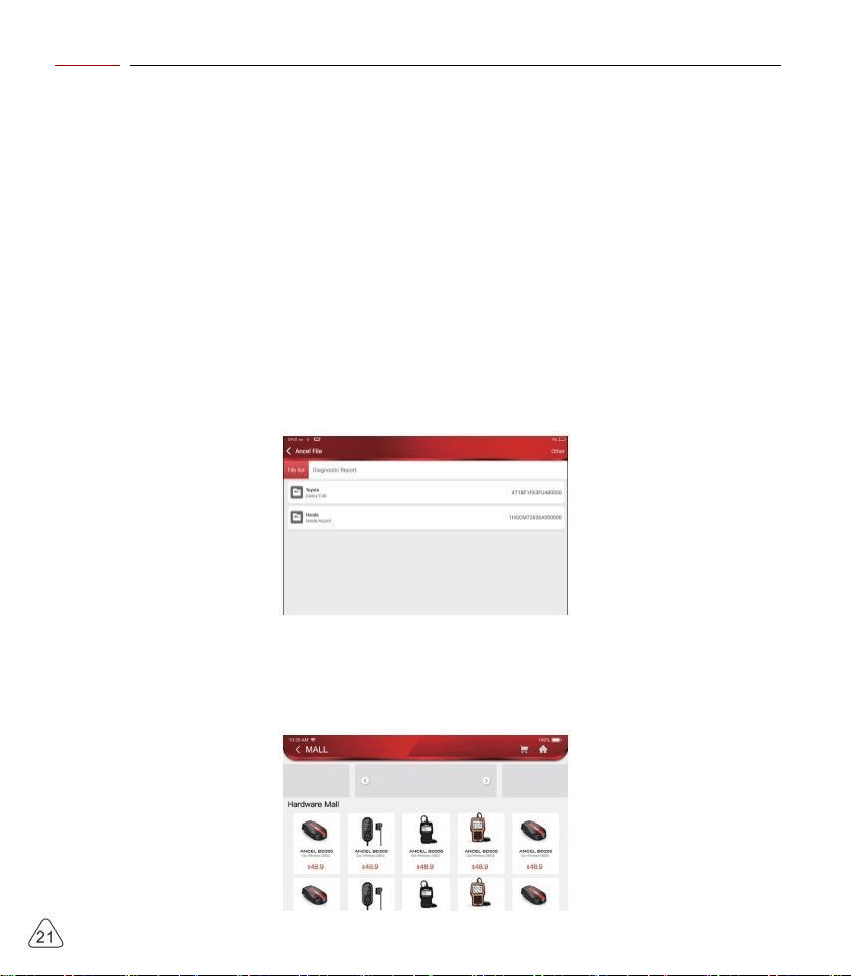
3.8 ANCELFile
t is used to record and establish the file of the diagnosed vehicles. The file is created based on the vehicle
VIN and check time, including all VIN-related data such as diagnostic reports, data stream records and
pictures.
3.9 ANCELStore
ANCELStore, released by ANCEL TECH, in which you can download all diagnostic software and purchase
hardware products. In the store, vehicle diagnostic and maintenance software can be bought. Each
diagnostic software has a detailed function introduction. All hardware products can also be purchased
online.

www.anceltech.com
ANCEL
4.Software Update
4.1 Upgrade all Software
In order to let you enjoy better functions and upgrade services, we recommend you make software
upgrades irregular. When there is a newer software version, the system will remind you to upgrade.
Click "Software Upgrade" to enter the upgrade center. There are two function tabs on the upgrade page:
Upqr a dd so t an n
45/132001
48132001
48132081
48132081
45130001
W1141
t.s
2a5W
216M
225M
475M
1.1M
72W
Upgradeable software: A list of software that can be upgraded to newer versions.
Upgraded software: a list of software that has been downloaded.
Note: During the upgrade, please keep normal network connection. Upgrade many software may take a few
minutes, please wait.
If you need to cancel certain software, please enter setting -> diagnostic software clear -> remove software
to operate.
5.Set Up
5.1 VCI
If several VCl connectors are registered on this ANCEL DS, this option allows you to choose one from
those.
5.2 Activate VCl
This item lets you activate a new VCl connectors or get help. Input the Serial Number and Activation Code,
and then tap "Activate" to activate it.
Serial Number
Activation Code
Actvate
W1445
wmans
ma1
wa
an

ANCEL
www.anceltech.com
Once the VCl connector activated, the serial number of it will be displayed in the list.
5.3 Fix VCl firmware/system
Used to repair the VCl firmware. During the repair, please don't power off or switch interfaces.
5.4 Data Stream Sample
This feature allows you to manage the recorded data stream sample files.
5.5 My Order
Used to manage order details.
5.6 Profile
Used to set and manage personal information.
5.7 Change Password
This item allows you to modify your login password.
5.8 Wi-Fi Settings
Set up Wi-Fi networks that can be connected.
5.9 Diagnostic Software Clear
This option can clear some cache files and free up the storage space.
5.10 Business Information
Add the information of the workshop, to which the scanner belongs, and it will be displayed to the
customers in the diagnostic report.
5.11 Customer Management
Manage information of all customers, who did vehicle diagnostic on this equipment and display in turn.
5.12 Photo Album
This module saves the screenshots.
5.13 Screen Recorder
This module saves the screen recordings.
5.14 Settings
This option makes settings including Units, Language, Clear Cache, Mode Switch, Restore Factory

www.anceltech.com
ANCEL
Settings, and Log Out.
5.15 Hotkey Setting
Including: Wi-Fi, Bluetooth, screen recording, screenshot, screen fip,brightness and sound.
6.FAQ
Q: Can I use the same type of charger to charge the tablet?
A: No, please use original charger. Our company is not responsible for any damage and economic loss
caused by using charger, which is not provided by ANCEL.
Q: How to save power?
A: Please turn off the screen while the equipment isn't used, set a shorter standby time, and decrease the
Q: The tablet cannot be turned on after charging
Passible reasons
Solution
The equipment has not been used for
a long time, and the battery loss
Charge it for more than 2 hours before turning it on
Problem of Charger
If there is a quality problem, please contact the dealer or
after-sales service of ANCEL.
Q:Why can't make register?
Passible reasons
Solution
The equipment isn't connected
Please make sure the network is connected
Notes that your email has been
registered.
Use another email for register or log in with the username
registered by the email (If you forget the username, you
can retrieve it by email)
The email didn't receive the verification
code during the registration
Check if the email is correct and get the verification code
again
brightness of the screen.

ANCEL
www.anceltech.com
Q: Why can't log in?
Passible reasons
Solution
The equipment isn't connected
Please make sure the network is connected
The user name or password is
incorrect
Check the user name and password
Contact ANCEL after-sales service or regional sales to
etrieve the user name and password
Server problem
Server maintenance, please try again later
Q:Why can't activate the equipment?
Passible reasons
Solution
The equipment isn't connected
Make sure the network is connected
The serial number and activation code
are inputted wrong
Check the serial number and activation code and make
sure they are correct (Serial number 12 digits, activation
code 8 digits).
The activation code is invalid
Contact ANCEL after-sales service or regional sales
Notes that the configuration is empty
Contact ANCEL after-sales service or regional sales
Q: Notes: the equipment is not activated during update software ?
Passible reasons
Solution
The VCl connector may not be
activated during registration
Use the serial number and activation code to activate the
connector
Steps are as follows: Click [Settings]->[Activate VCl]
Enter the correct serial number and activation code in the
interface, and click [Activate].
Q: Software upgrade failed.
Passible reasons
Solution
The equipment is not connected to the
Internet
Check its network connection
The user name or password is wrong
The equipment has not enough
memory
Check the user name and password
Uninstall irrelevant applications and delete uncommonly
used vehicle software(enter setting -> diagnostic
software clear -> remove software to operate)
Server problem
Server maintenance, please try again later

www.anceltech.com
ANCEL
Q: There is no power in the VCl dongle after connecting to the vehicle's DLC port.
Passible reasons
Solution
Poor contact of vehicle's DLC port
Plug out the VCl dongle, and then plug it in again
Too low voltage of the vehicle battery
· Recharge the vehicle battery.
·Replace the vehicle battery if it is damaged
Damage of the VCl dongle
Contact ANCEL after-sales service to get support
Q: The tablet cannot establish a connection with the VCl dongle.
Passible reasons
Solution
Poor contact of the VCl dongle
Plug out the VCl dongle, and then plug it in again
· Perform the VCl Bluetooth pairing again
The firmware is damaged
Enter the settings and tap "Fix Connector Firmware/
System" to fix the firmware
Q: How about non-standard OBDII VCl connector
A: There is a several non-standard adapters in the box, Follow the instructions to connect.
Q: Communication error with vehicle ECU?
A: Please confirm:
Whether the VCl is correctly connected and whether the vehicle ignition switch is ON.
If all are normal, send vehicle production year, model and VIN number by Feedback feature.
Q: Failed to enter into vehicle ECU system?
A: Please confirm:
Whether the vehicle is equipped with the system,whether the VCl is correctly connected, and whether
the vehicle ignition switch is ON.
Q: What to do if the connector is missing
A: Contact ANCEL after-sales service or regional sales.
Q: The downloaded diagnostic software is inconsistent with the serial number
A: There are several connectors registered under the equipment account, and the serial number of right
connector has not been selected.
Enter the settings-[VCl] and select the right serial number of connector. Delete the software with
problems, then enter the upgrade center to download the diagnostic software again.

ANCEL
www.anceltech.com
Warranty Terms
This warranty applies only to users and distributors who purchase ANCEL products through normal
procedures. Within one year from the date of delivery, ANCEL warrants its electronic products for damages
caused by defects in materials or workmanship. Damages to the equipment or components because of
abuse, unauthorized modification, use for non-designed purposes, operation in a manner not specified in
the instructions, etc. are not covered by this warranty. The compensation for dashboard damage caused
by the defect of this equipment is limited to repair or replacement. ANCEL does not bear any indirect
and incidental losses. ANCEL will judge the nature of the equipment damage according to its prescribed
inspection methods. No agents, employees or business representatives of ANCEL are authorized to make
any confirmation, notice or promise related to ANCEL products.
OBDSPACE Tech Co., Ltd
Service Line:0755-81751202
Customer Service Email: support@anceltech.com
Offic ia l Web si te: www.ance lt ech.com
Produc ts tutorial , videos, Q& A an d cover a ge list ar e availa bl e on ANCEL of fi cial we bsite.