
SUPER+ MULTI ULTRA Series
R410A
Systems―Outdoor Unit
Installation & Owner's Manual
Gree Air Conditioners
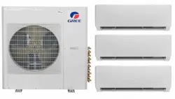
MULTIU48HP230V1BO
GWHD(48S)HD3DO
Thank you for choosing Gree air conditioners, please read this installation & owner’s manual
carefully before operation and keep it for future reference.
GREE reserves the right to change this contents of this manual without notice due to product
improvement or modification.
GREE Electric Appliances, Inc. of Zhuhai reserves the final right to interpret this manual.

Preface
Super Free Match Series adopt the advanced manufacturing technology and takes the
environmental-friendly R410A as refrigerant, which is a green product in the 21st century. Please
carefully read the manual before installation and operation.
1) Super Free Match Series systems conform to design standard ARI 210240-2008.
2) To ensure safety when operating this system, please strictly follow the instructions in this
manual.
3) Make sure that the manual is kept by the operators or serviceman.
4) The refrigerant pipes and accessories must be designed exclusively for R410A.
5) The total capacity of the indoor units which runs at the same time cannot exceed the capacity of
the outdoor units; otherwise, the cooling (heating) effect of each indoor unit would be lower
than the nominal capacity.
6) In case of malfunction, please examine the following items and contact our appointed service
centers as soon as possible.
Nameplate (model, cooling capacity, product code, ex-factory date).
Malfunction status (detail description of conditions before and after malfunction occurs).
7) It is a normal phenomenon that the fan of indoor unit will still run for 20~70 seconds after the
indoor unit receives the “stop” signal so as to make full use of the waste heat.
8) When the work mode of the indoors is conflict with the modes of outdoor units, it will be
indicated on the display of the wired controller in five seconds and then the indoor unit will
stop. In this case, please harmonize their work modes: the cooling mode is compatible with the
dry mode.
9) If the supply power fails when the unit is running, then the indoor unit will send the “start”
signal to the outdoor unit three minutes later after the power recovery.
10) The power cable and transmission line must not be twisted together, but instead of separated
with an interval of at least 2cm; otherwise it may be result in communication problem.
11) This appliance is not intended for use by persons (including children) with reduced physical,
sensory or mental capabilities, or lack of experience and knowledge, unless they have been
given supervision or instruction concerning use of the appliance by a person responsible for
their safety. Children should be supervised to ensure that they do not play with the appliance.
12) All graphics and information in this manual are only for reference. Manufacturer reserves the
right for changes in terms of sales or production at any time and without prior notice.
This product must not be disposed together with the domestic waste. This product has
to be disposed at an appointed place for recycling of electrical and electronic appliances.
Thank you for purchasing GREE air conditioners. Before using, please read this
manual carefully and keep it properly for further reference.


I
Contents
1 Safety Precautions ..................................................................................................................... 1
2 Attention for Installation ........................................................................................................... 3
2.1 Precautions for R410A .................................................................................................. 3
2.2 Precaution for Installation ............................................................................................. 3
2.3 Precaution for Operation Test........................................................................................ 3
2.4 Accessories .................................................................................................................... 3
3 Product Introduction ................................................................................................................. 4
3.1 Names of Main Parts ..................................................................................................... 4
3.2 Combinations for Outdoor and Indoor Units ................................................................ 4
3.3 Parts and Components of Unit ...................................................................................... 5
3.4 Working Temperature Range ......................................................................................... 5
4 Selection of Installation Location and Precautions ................................................................... 6
4.1 Selection of Installation Location ................................................................................. 6
4.2 Outline Dimension of Outdoor Unit .............................................................................. 7
4.3 Installation and Servicing Space ................................................................................... 7
5 Installation Instruction .............................................................................................................. 8
6 Installation of Refrigerant Pipes ............................................................................................... 9
6.1 Allowable Length and Drop Height of Connecting Pipe .............................................. 9
6.2 Dimension of Connecting Pipe ................................................................................... 10
6.3 Connection of Branch Pipe ......................................................................................... 10
6.4 Connection of Refrigerant Pipes ................................................................................. 11
6.5 Connec
tion of Refrigerant Pipe ................................................................................... 12
6.6 Leak Test ..................................................................................................................... 13
6.7 Vacuum Operation ....................................................................................................... 13
6.8 Refrigerant Charging ................................................................................................... 14
7 Electrical Wiring Work ........................................................................................................... 17
7.1 Wiring Connection ...................................................................................................... 17
7.2 Requirements of Power Circuit and Cable .................................................................. 17
7.3 Ground Requirements ................................................................................................. 18
7.4 Precautions on the Electrical Wiring Work ................................................................. 18
7.5 Precaution of Laying Wires ......................................................................................... 19
7.6 Procedures for Electrical Wiring Work ....................................................................... 19
8 Design of Drainage Pipeline ................................................................................................... 20
8.1 Installation of Drain Hose ........................................................................................... 20
8.2 Design of Drainage Pipeline ....................................................................................... 20
9 Installation of Protective Layer ............................................................................................... 21
10 Test Operation ......................................................................................................................... 22
10.1 Check after Installation ............................................................................................... 22
10.2 Test Operation ............................................................................................................. 22
11 Testing Board Introduction ..................................................................................................... 23
11.1 Compose of the Testing Board .................................................................................... 23
11.2 Instruction of Function and Data Section .................................................................... 23

II
12 Troubleshooting ...................................................................................................................... 24
12.1 Check before Contacting Service Center .................................................................... 24
12.2 Problem Handling ....................................................................................................... 25
12.3 Error Description ......................................................................................................... 25
13 Maintenance ............................................................................................................................ 28
13.1 Outdoor Condenser ..................................................................................................... 28
13.2 Drain Pipe ................................................................................................................... 28
13.3 Check before the Seasonal Use ................................................................................... 28
13.4 Maintenance after Seasonal Use ................................................................................. 28
14 After-sales Service .................................................................................................................. 28
Super Free Match Series
1
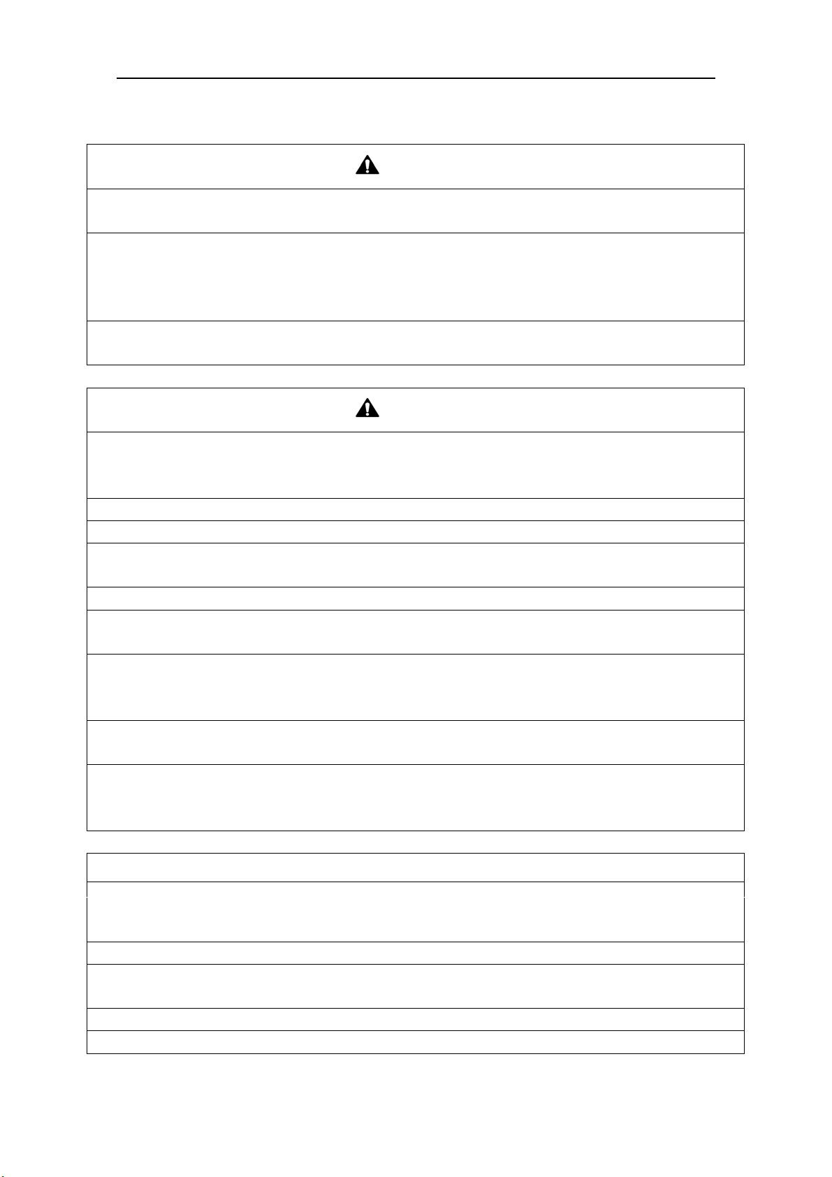
1 Safety Precautions
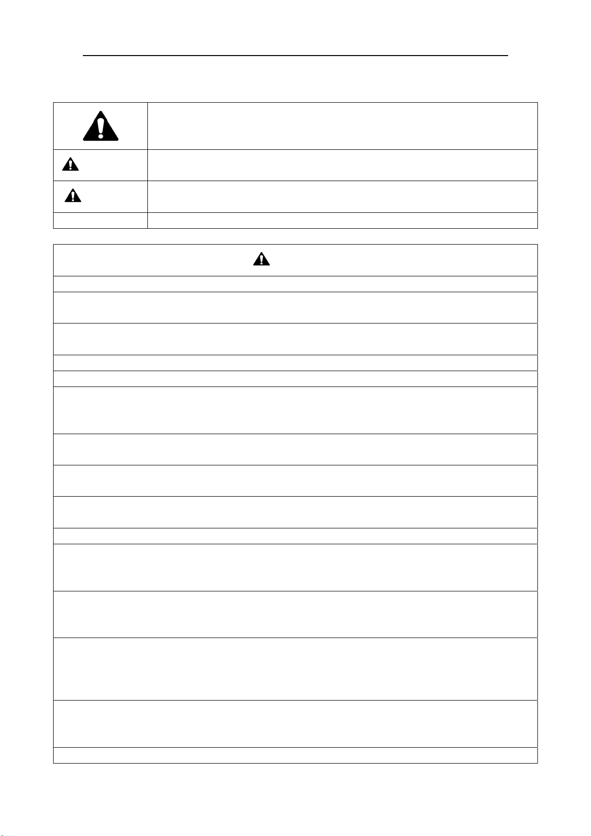
This is t
he safety alert symbol. It is used to alert you to potential personal injury
hazards. Obey all safety messages that follow this symbol to avoid possible injury or
death.
WARNING
This mark indicates procedures which, if improperly performed, might lead to the
death or serious injury of the user.
CAUTION
This mark indicates procedures which, if improperly performed, might possibly result
in personal harm to the user, or damage to property.
NOTICE
NOTICE is used to address practices not related to personal injury.
WARNING
1) Instructions for installation and use of this product are provided by the manufacturer.
2) Installation must be performed in accordance with the requirements of NEC and CEC by appointed
personnel only.
3) The installation should be left to the appointed service center and according to the instructions given in the
manual. Improper installation may cause fall down, water leakage, electric shock or fire etc.
4) For operating the air conditioner pleasantly, please install it as outlined in this installation manual.
5) The power supply must adopt the special circuit with air switch protection and assure it has enough capacity
6) Connect the indoor unit, BU module and outdoor unit with the room air conditioner piping and cord
available from our standard parts. This installation manual describes the correct connections using the
installation set available from our standard parts.
7) Before installation, check the parameter of power cord and make sure that it complies with the power
supply requirement on the nameplate. Make sure the power supply is safe.
8) This air conditioner must be properly grounded through the receptacle to avoid electric shock. The ground
wire shouldn’t be connected with gas pipe, water pipe, lightning arrester or telephone line.
9) If refrigerant leaks while work is being carried out, ventilate the area. If the refrigerant comes in contact
with a flame, it produces toxic gas.
10) Do not power on until all installation work is complete.
11) During installation, make sure that the refrigerant pipe is attached firmly before you start up the compressor.
Do not operate the compressor under the condition of refrigerant piping not attached properly with valve
open. This may cause abnormal pressure in the refrigeration cycle that leads to breakage and even injury.
12) When installing and relocating the air conditioner, do not mix gases except the specified refrigerant
(R410A) to enter the refrigerant cycle. If air or other gas enters the refrigerant cycle, the pressure inside the
cycle will rise to an abnormally high value and cause breakage, injury, etc.
13) This appliance is not intended for use by persons (including children) with reduced physical, sensory or
mental capabilities, or lack of experience and knowledge, unless they have been given supervision or
instruction concerning use of the appliance by a person responsible for their safety. Children should be
supervised to ensure that they do not play with the appliance.
14) Never cut off or damage power cables and transmission wires. If the power cable or transmission line were
damaged, it must be replaced by the manufacturer, its service agent or similarly qualified persons in order to
avoid a hazard.
15) After the power cord is connected, please install the cover of electric box to avoid danger.
Super Free Match Series
2
16) When installing or relocating the unit, please contact the appointed service center for the repair or
relocation. Meanwhile the specialized parts and accessories must be used. Otherwise, it may result in water
leakage, electric shock or fire hazard.
17) Diameter of power cord must be large enough. Damaged power cord or connecting wire must be replaced
by specialized electric cable.
18) The power wire and transmission line must be more than one meter away from televisions or radios which
can emit electromagnetic waves to prevent image interference or noise. Otherwise, the unit maybe not work
19) Nitrogen must be charged according to technical requirements.
20) For units with wired controllers, do not connect power supply until the wired controller is well installed.
Otherwise, the wired controller cannot be used.
21) When installation is finished, please check and make sure the drain pipe, pipeline and electric wire are all
well connected so as to avoid water leakage, refrigerant leakage, electric shock and fire hazard.
22) Never extend fingers or objects into air outlet or return air grille.
23) Please keep the room well-ventilated and it could avoid oxygen deficit.
24) Never start or stop the air conditioner by inserting or removing the power cord.
25) Before startup of the compressor, please turn on the main power switch of the unit for more than 8 hours
and it makes sure that the heater belt of the compressor has been energized for at least eight hours! Once the
compressor is started, it must be guaranteed that it works continuously for at least 30 minutes, otherwise it
would be damaged!
26) Never operate the unit with wet hands. Otherwise, it may cause electric shock.
27) Before cleaning and repairing, it is necessary to stop working and turn off the power supply. Otherwise, it
may cause electric shock or damage.
28) Do not spray water on the air conditioner or it will cause malfunction or electric shock.
29) The air conditioner is not support to install in the circumstances as the following that where there is full of
mist of oil, damp or corrosive gas, flammable gases, the acidic or alkaline vapor and the ocean.
30) Volatile liquid like thinner or gasoline will damage the appearance of air conditioner. (Please use soft dry
cloth and wet cloth with mild detergent to clean unit’s appearance.)
31) Never standing or place objects on outdoor unit. Person or objects falling from the unit may cause injury.
32) If abnormal condition occurs (e.g. unpleasant smell), please turn off the unit at once and disconnect power
supply. Then contact appointed service center. If the air conditioner continues to operate despite of
abnormal condition, it may be damaged and cause electric shock or fire hazard.
33) The drain pipe should be installed as instructed in the manual to guarantee the proper drainage; meanwhile
it should be insulated to prevent condensing; otherwise the improper installation would cause water leakage
and then wet the household wares in the room.
34) Don't attempt to repair the air conditioner by yourself. The improper repair will lead to electric shock or
fire, please contact the appointed service center and ask professional technicians to repair it.
35) Please take notice of the installation foundation of the unit after long use, if it is damaged, it may lead to the
fall of the unit and cause the injury.
36) Be sure to shut off the power supply when you do not use the air conditioner for a long time. Otherwise, the
dusts may accumulate in it, which may cause overheating or fire hazards.
37) Gree Electric Appliances, Inc. of Zhuhai is not responsible for any personal injury or property loss caused
by improper installation, improper debugging, unnecessary repair or not following the instructions of this
manual.

Super Free Match Series
3
2 Attention for Installation
2.1 Precautions for R410A
It is very strict that the refrigerant pipes should be clean and dry.
The R410A is a mixed refrigerant, when add the refrigerant to the unit, it must keep the
refrigerant in its liquid state. If the refrigerant is in gas state, the composition has been changed
and the capability of the unit will decrease.
When the refrigerant is leak out, please do not touch the leakage. Otherwise, it will result in
frostbite.
It does not support to let a lot of refrigerant go into the ambient atmosphere, because it will
strengthen the green house effect. Otherwise, it will produce toxic gas when the refrigerant
contacts with the fire.
2.2 Precaution for Installation
The unit is so heavy that it is more than 110kg, so more than two persons will be needed to
remove the unit. The package cannot bear it, so do not grasping it.
When remove the units, please place the hands on the corner and take care not to hurt the hands
by the fins.
It is very likely to dispose the waste to the garbage bin after the installation.
2.3 Precaution for Operation Test
In order to protect the compressor from vibrating during transportation and 2 metal gaskets are
used. They must be removed prior to commissioning and tied back the nut firmly; otherwise the unit
might not be operated well.
2.4 Accessories
For the accessories of the air conditioner, please look out the Packing List in the package.
Super Free Match Series
4
3 Product Introduction
The Gree Super Free Match System adopts inverter compressor technology. According to
change displacement of compressor, stepless capacity regulation within range of 15%~100% can be
realized. Various product lineups are provided with capacity 48000Btu/h, which can be widely used
in residential house, business office, hotel and where especially applicable to the place with variable
load change. Gree air conditioner is absolutely your best choice.
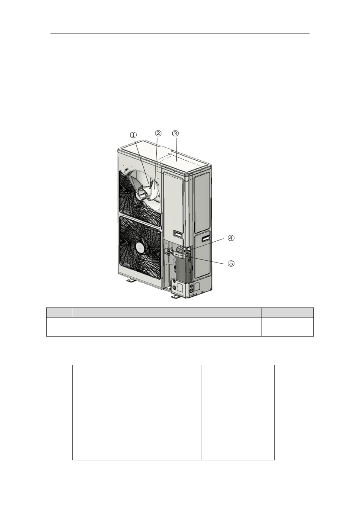
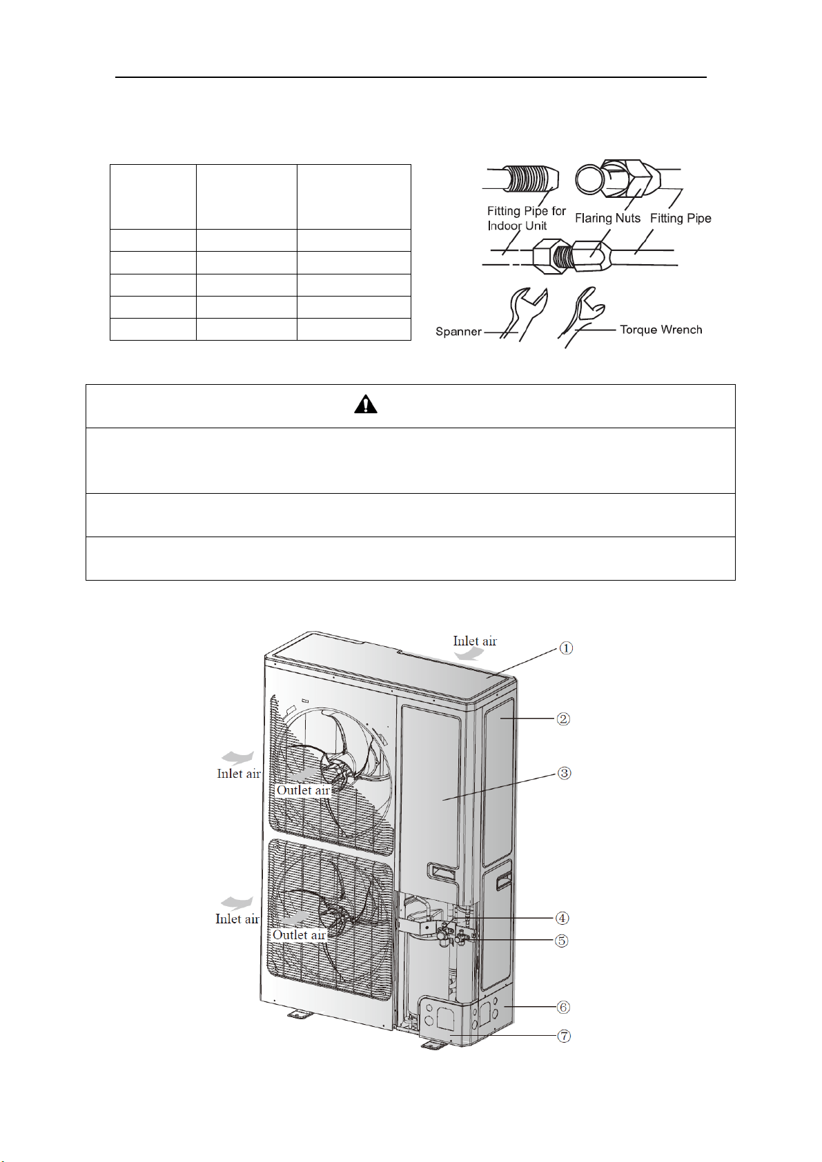
3.1 Names of Main Parts
NO. ① ② ③ ④ ⑤
Name Fan motor Axial flow fan blade Electrical box
Gas side stop
valve
Liquid side stop
valve
Fig. 1
3.2 Combinations for Outdoor and Indoor Units
Table 1
Sorts
MULTIU48HP230V1BO
No. of indoor units to be
connected
2 niM
7
xaM
No. of BU modules to be
connected
1 niM
3 xaM
Total capacity of indoor units to
be connected(Btu/h)
Min 24000
Max 65000
Super Free Match Series
5
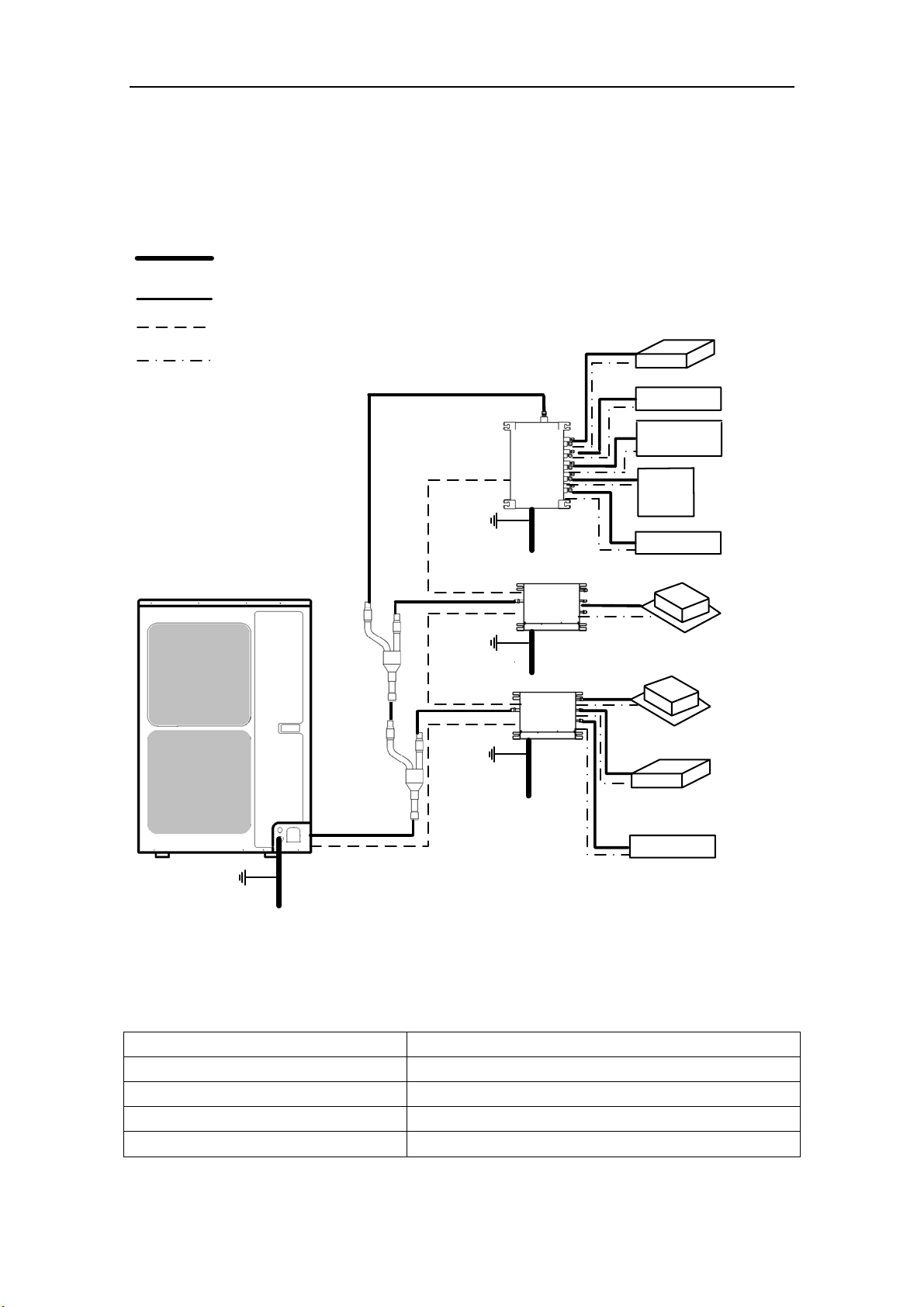
3.3 Parts and Components of Unit
For the super free match series, one outdoor unit is able to drive up to three BU modules and
nine indoor units which include cassette type, duct type, wall mounted type, floor ceiling type and
console type. The outdoor unit will run as long as any one indoor unit receives the running command,
and all indoor units stop once the outdoor unit is turned off.
Fig. 2
3.4 Working Temperature Range
Table 2
Sorts
Maximum cooling 54℃(129℉)
Minimum cooling 10℃(50℉)
Maximum heating 27℃(81℉)
Minimum heating -35℃(-31℉)
Outdoor unit
Power supply wire for outdoor
unit and BU module(3 wires)
Connection pipe
Transmission line(2 wires)
Power supply wire for
indoor unit(4 wires)
Ground
Power
(60Hz, 208/230V)
Power
(60Hz, 208/230V)
Power
(60Hz, 208/230V)
Power
(60Hz, 208/230V)
Ground
Ground
The 1st
branch
The 2nd
branch
BU 1
BU 2
BU 3
Indoor unit
Duct type
Duct type
Wall mounted
type
Wall mounted
type
Wall mounted
type
Cassette type
Cassette type
Floor ceiling
type
Console type
Ground
Outside temperature:DB(℃/℉)
Super Free Match Series
6
4 Selection of Installation Location and Precautions
WAR NI NG
7
) Whenever possible, install unit in shaded, wind protected areas to improve unit efficiency. Installation
d
esign should provide optimal consideration for year around ambient conditions. Consult an architect
or engineer to assist in installation design.
8) Do not install in the place where there is heat source, flammable or explosive gas, a place subject to
severe dust, salty fog and polluted air.
9) Installation at the following places might lead to the air conditioner malfunction, such as where is full of
machine oil, saline-sodic soil near the sea, sulphide fog, high frequency facilities or special conditions.
If it is unavoidable, please contact the appointed service center.
NOTICE
1
) Whenever possible, install unit in shaded, wind protected areas to improve unit efficiency. Installation
design should provide optimal consideration for year around ambient conditions
2) Whenever possible, excessive exposure to damp an
d dirty environments should be avoided.
3) Outdoor unit shall be installed close to the indoor unit, hence to minimize the length and bends of
cooling pipe.
4) Do not place animals and plants in the path of the air inlet and outlet of the units.
5) Make sure that the unit will not cause any operating vibration or noise after installation.
1) The installation of the air conditioner must be in accordance with the national and local laws and
regulations.
2) The quality of the installation will affect the capability of air conditioner directly. The installation
should be left to a licensed HVAC technician. Please contact your dealer if you have any questions
after installation. Licensed HVAC technicians will provide installation, testing and service in
accordance with the installation manual.
3) Installations where the small animals exist, may require field installed protections. Failure to do so
may cause malfunctions, smoke or fire. Please keep the area around the unit clean.
4.1 Selection of Installation Location
WAR NI NG
1) The outdoor unit must be installed on a firm and solid support which can withstand the weight,
meanwhile the mounting surface must be in a horizontal plane. Otherwise, the unit could tip over
and cause injury or
death.
2) The location must be out of children’s reach, please keep the unit away from children.
3) During installation, if the outdoor unit has to be exposed to strong wind, it must be properly secured.
4) Provide enough space for the installation and maintenance. Ensure there are no obstacles near
the air inlet and outlet of the indoor and outdoor units.
5) The space
should be well-ventilated for proper inlet and outlet air circulation.
6) Avoid place the outdoor unit under the windows or between the constructions, hence to prevent normal
operating noise from entering the room.
Super Free Match Series
7
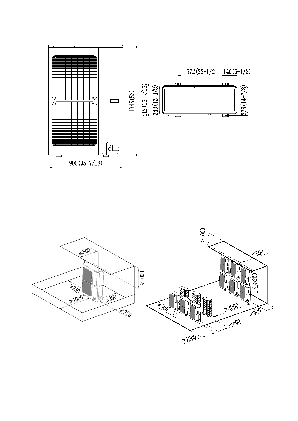
4.2 Outline Dimension of Outdoor Unit
Fig.
3 (unit: mm/inch)
4.3 Installation and Servicing Space
1) In case of installing only one unit
In case obstacles exist around the unit, the required installation space is in the Fig. 4.
2) In case of installing multiple units(2 units or more)
In case multiple rows of series installation, the required installation space is in the Fig. 5.
Fig. 4 (unit: mm) Fig. 5 (unit: mm)
Super Free Match Series
8
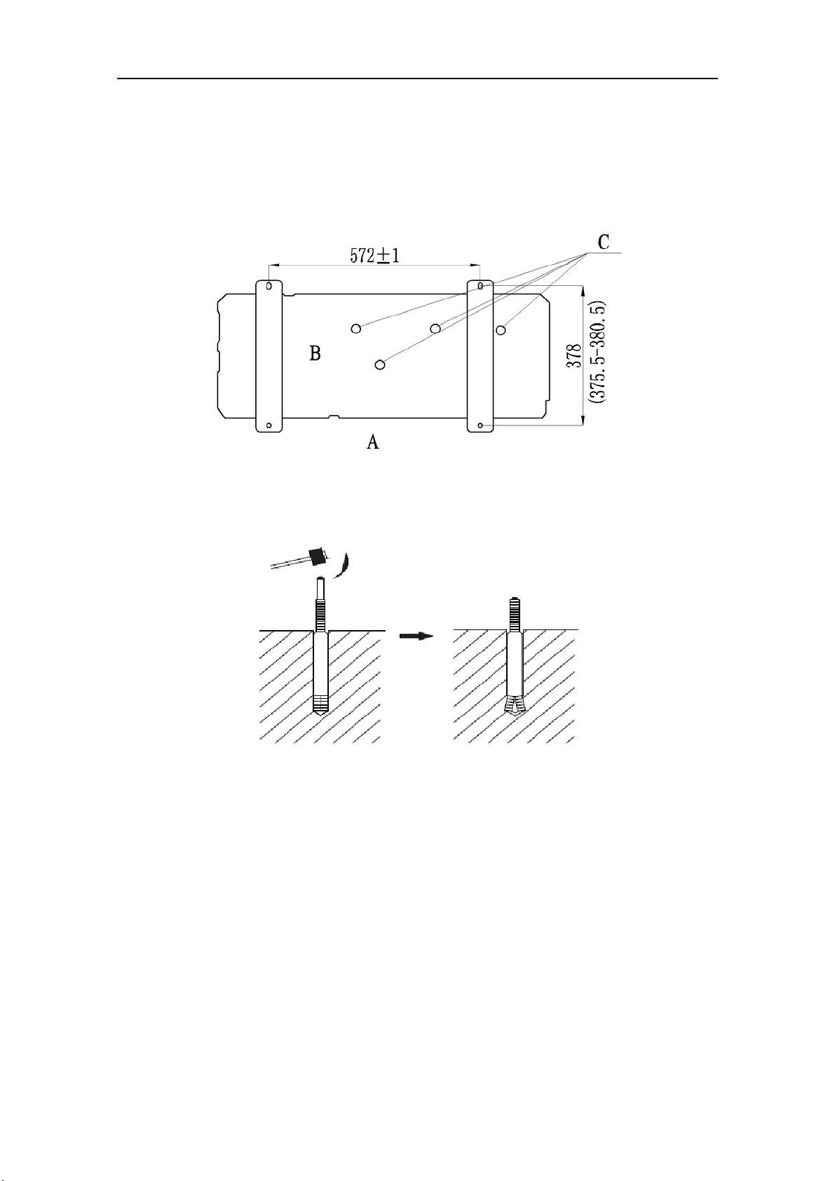
5 Installation Instruction
1) Check the installation location and ensure it is strength and level, so that the unit will not cause
any operating vibration or noise after installation.
2) In accordance with the foundation drawing in the following figure, please drill 4 holes in the
installation location.
A
: The outlet side B: Bottom view (mm) C: Drain hole
Fig. 6
3) Fix the unit securely with the foundation bolts. You can get the M10 or M12 foundation bolts,
nuts and washers from the market.
Fig. 7
4) Rub
ber or spring shock absorbers should be used during the installation of the outdoor unit to
meet the noise and vibration requirements.
5) Screw the foundation bolts into the ground and it is better that its length is less than 20mm
(4/5inch) from the foundation face.
Super Free Match Series
9
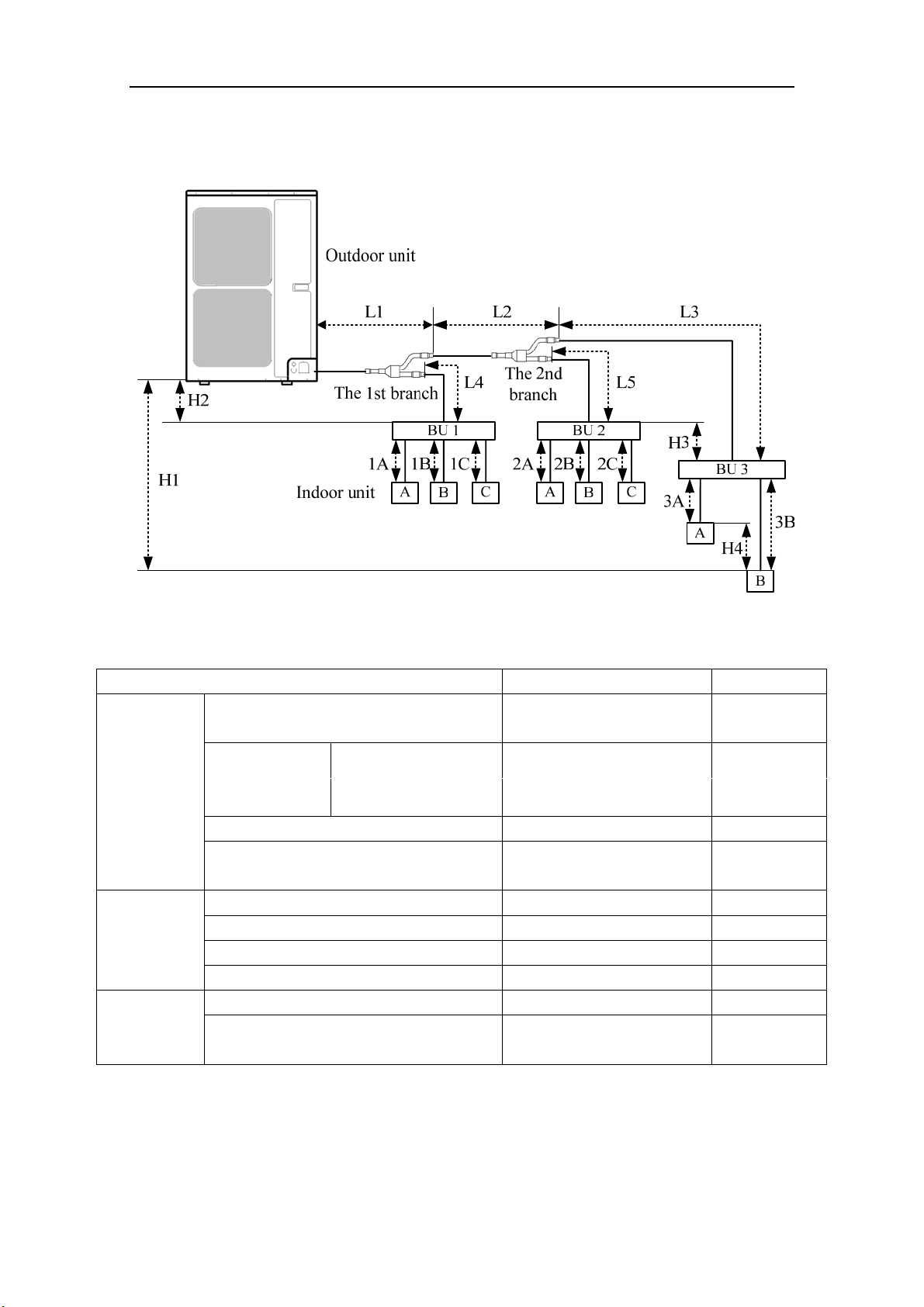
6 Installation of Refrigerant Pipes
6.1 Allowable Length and Drop Height of Connecting Pipe
Fig. 8 (8 indoor units)
Table 3
)teef/m(htgneL sepip ehT stros ehT
Maximum
allowable
length
Total length between outdoor unit and BU
modules
L1+L2+L3+L4+L5 ≤55(181)
Total length
between indoor
units and BU
MULTIU48HP230V1BO
GWHD(48S)HD3DO
1A+1B+1C+2A+2B+2C+
3A+3B
≤80(263)
Between indoor unit and BU module 1A;1B;1C;2A;2B;2C;3A;3B ≤15(49)
Between indoor unit and the 1st branch
L4+1B;L2+L5+2A;
L2+L3+3B
≤40(131)
Maximum
allowable
length
Between outdoor and indoor units H1 ≤30(99)
Between outdoor units and BU modules H2 ≤30(99)
Between BU and BU modules H3 ≤15(49)
Between indoor and indoor units H4 ≤15(49)
Minimum
allowable
length
Between outdoor and the 1st branch L1 ≥5(16)
Between BU and the branch L3;L4;L5
as possible as
short
NOTICE! BU module should be placed within the level between the outdoor unit and indoor
unit.
Super Free Match Series
10
6.2 Dimension of Connecting Pipe
Table 4
Sorts
Gas Pipe
(mm/inch)
Liquid Pipe
(mm/inch)
Outdoor unit
MULTIU48HP230V1BO
Φ15.9(5/8) Φ9.52(3/8)
Between outdoor unit and the
1st branch
The pipe L1 Φ19.05(3/4) Φ9.52(3/8)
Between the 1st and the 2nd
branch
The pipe L2 Φ15.9(5/8) Φ9.52(3/8)
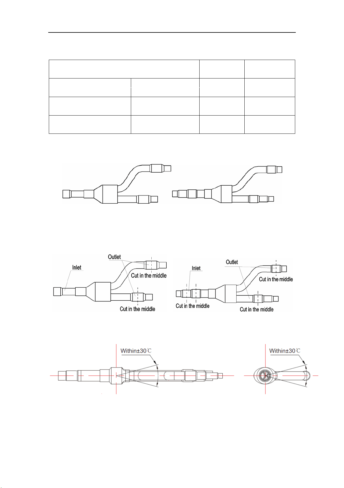
6.3 Connection of Branch Pipe
1) If two or three BU modules used, Y-type branch pipe of FQ01A/A will be chosen.
FQ01A/A (Liquid pipe) FQ01A/A (Gas pipe)
Fig. 9
2) Y-type branch pipe is equipped with auxiliary tubes to adjust the diameter of different pipes. If
the dimension of the pipe selected is different from the dimension of branch pipe joint, Cut the
copper tube in the middle with tube cutter and clear up burrs. Please do that as following figure.
Fig. 10
3) Y-type branch pipe must be installed in vertical or horizontal direction. In the inlet of the branch
pipe, keep at least 500mm straight pipe.
Fig. 11
Super Free Match Series
11
6.4 Connection of Refrigerant Pipes
CAUTION
1) Conform to the following principles during pipe connection: Outdoor unit shall be installed close to the
indoor unit, hence to minimize the length and bends of connection pipes; the height gap of outdoor unit
and indoor units should be as small as possible; the radius of curvature should be as large as possible.
2) The brazing operation must be strictly in accordance with the process requirements. Rosin joint or pin
hole is not allowed.
3) During the installation, do not damage the pipeline. The pipeline’s radius of bending must be over than
200mm(8inch). The pipes cannot repeatedly be bent or straightened. Otherwise it will get harden and
crack. Do not bend or straight the pipes for more than 3 times at the same position.
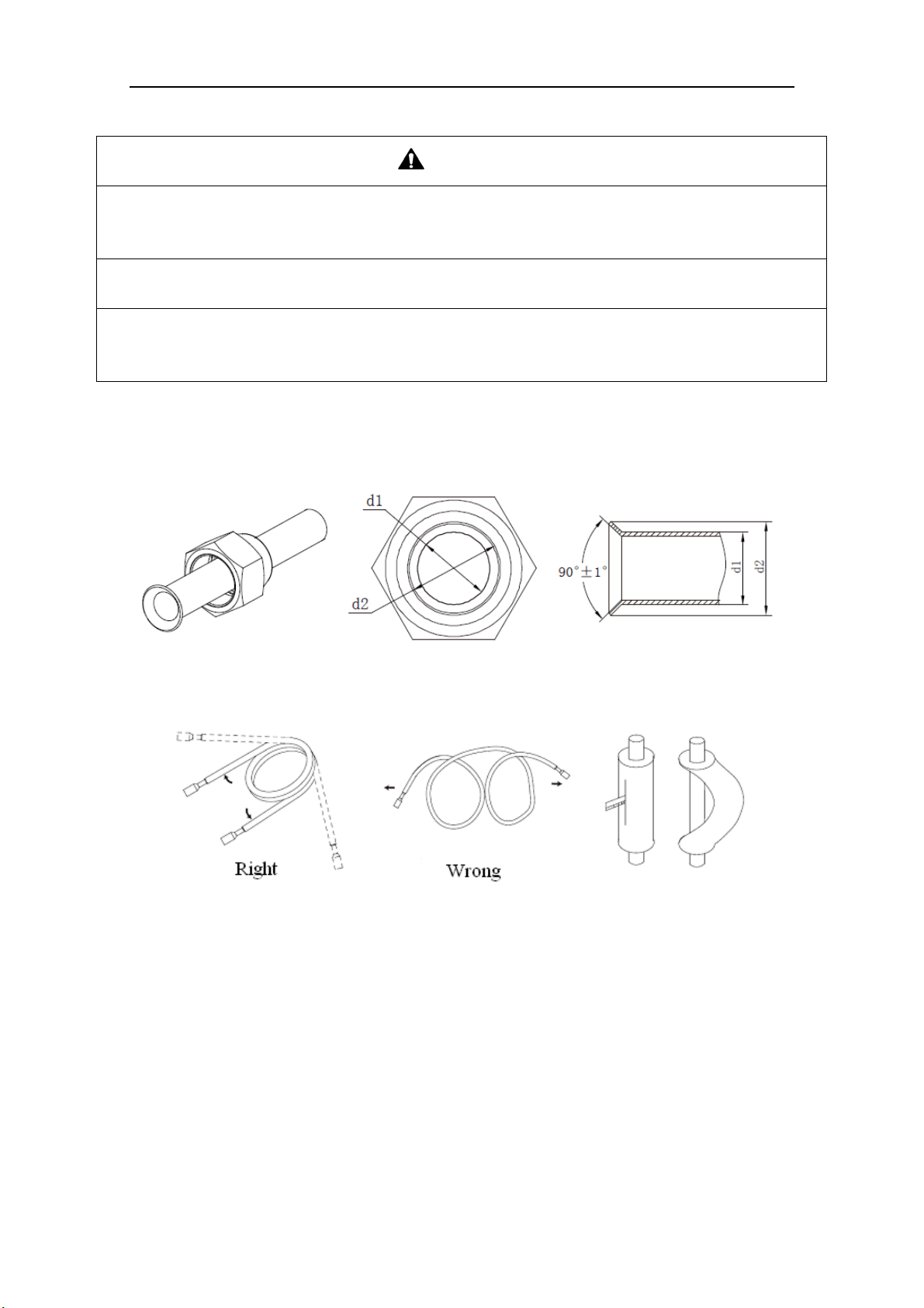
1) The process of flaring
① Using the tube cutter to cut the connecting pipe in the appropriate place and remove the burrs.
② Install the nut before the flaring operation.
③ Check the flared portion, whether there is fractured or not.
Fig. 12
2) Precaution for elbow operation
① The elbow operation could be done by hands. Be careful and do not damage the pipe.
Fig. 13
② If the thermal insulation of the refrigerant pipe is not removed, please do not bend the pipe.
Otherwise, it maybe leads the pipe to crack. It is better to make an incision with a knife in the
thermal insulation and removes it. After elbow operation is finished, recover the thermal
insulation with binding band.
3) The process of install refrigerant pipes
① Remove the screw caps from the pipes.
② Align the flared end of copper tube with the center of pipe joint. Tighten the nuts by hands. (If
the flared end of copper tube and the center of pipe joint are not in coaxial, it is hard to tighten
the nuts by hands, please do not tighten it with spanners, because the screw thread may be
broken by force).
③ Tighten the flaring nuts with torque wrench until you hear a “click”. (The spanner and torque
Super Free Match Series
12
wrench should be perpendicular to the refrigerant pipeline).
④ The following table for the torque required to tighten the nuts.
Table 5
Pipe
diameter
(mm/inch)
Thickness of
copper
tube(mm/inch)
Tightening
torque
(N·m/1bf·ft)
Φ6.35(1/4) ≥0.8(1/32) 15~30(11~22)
Φ9.52(3/8) ≥0.8(1/32) 35~40(26~29)
Φ12.7(1/2) ≥0.8(1/32) 45~50(33~37)
Φ15.9(5/8) ≥1.0(1/25) 60~65(44~48)
Φ19.05(3/4) ≥1.0(1/25) 70~75(52~55)
Fig. 14
CAUTION
1) During the connection of the indoor unit and BU module to the refrigerant pipe, never pull any joints of
the indoor unit and the BU module by force; otherwise the capillary pipe or other pipe may crack,
which then would result in leakage.
2) The refrigerant pipe should be supported by brackets, that is, don’t let the unit withstand the weight of
it.
3) For the Super Free Match system, each pipe should be labeled to tell which system it belongs to avoid
mistaken inaccurate piping.
6.5 Connection of Refrigerant Pipe
Super Free Match Series
13
NO. ① ② ③ ④
Name Coping plate Rear side plate Front side plate Gas side stop valve
NO. ⑤ ⑥ ⑦
Name Liquid side stop valve Right connection board Front connection board
Fig. 15
1) Unscrew the coping plate, front side plate, right connection board and front connection board.
2) The refrigerant pipes can be installed in four directions, please choose the proper direction.
3) Knock the holes in the plate of the chosen direction with the drill and hammer.
4) Connect the pipes to the stop valves.
5) Bend the pipes to go through the knockout holes.
6) Cover the through-holes with sealing materials to prevent the water, dust or small animals going
into the outdoor unit.
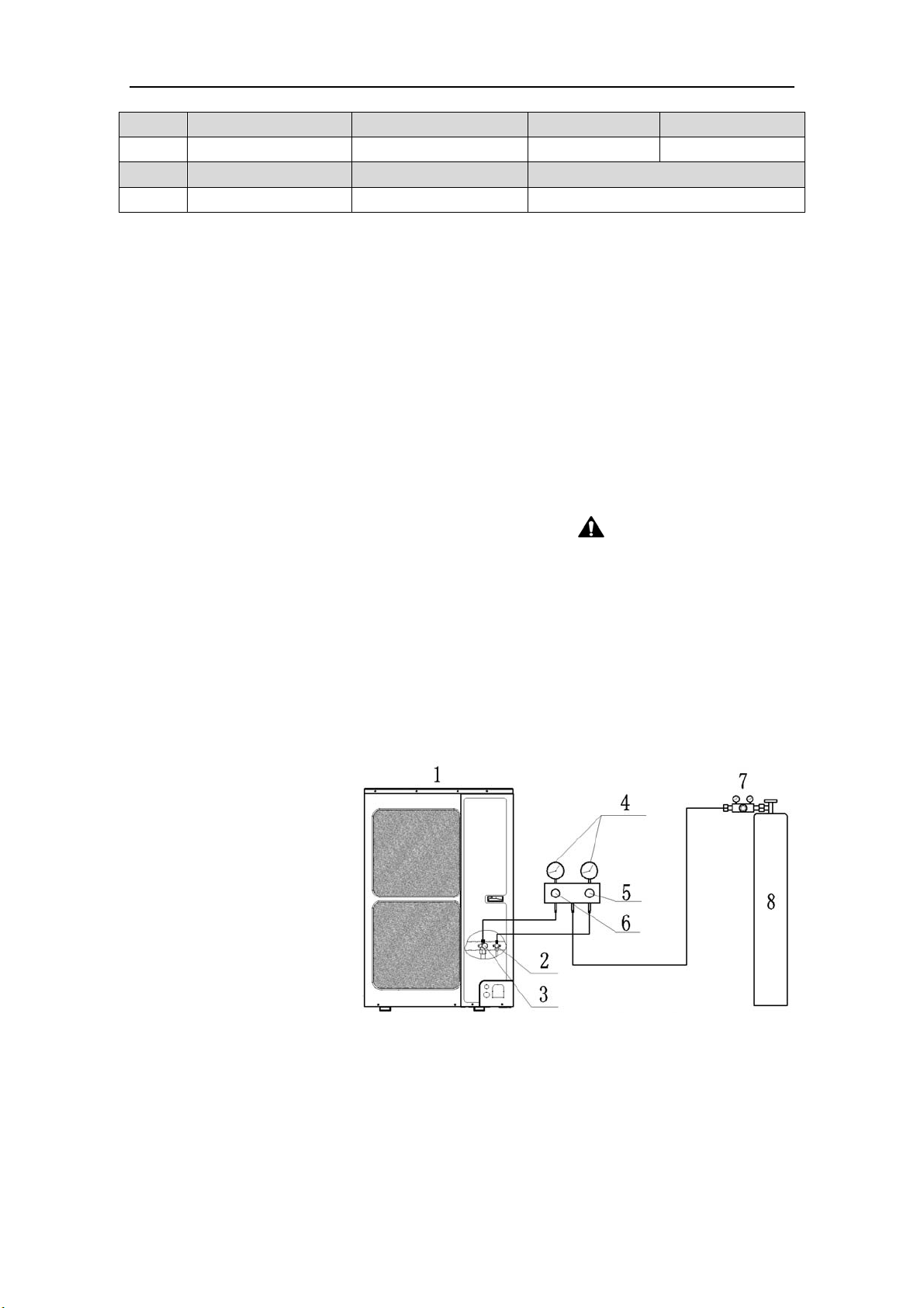
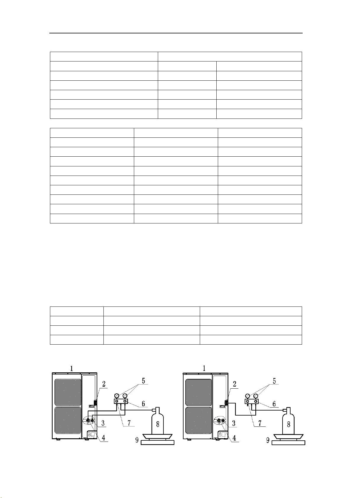
6.6 Leak Test
1) Please make sure that the stop valves of the outdoor unit are closed during the operation.
2) The leak test should be made by pressurizing nitrogen gas.
WARNING! Do not mix
oxygen, C
2
H
2
or other dangerous gas into the refrigerant circuit.
3) Turn on the Hi-knob and Lo-knob.
NOTICE! The leak test should be done simultaneously
at both the gas and liquid stop valves.
4) Open the pressure reducing valve, pressurize the connection pipes to 1.0 MPa (10 bar) slowly,
wait fifteen minutes, and make sure that the pressure will not drop.
5) Rise the pressure to 4.0 MPa (40 bar) slowly, wait 24 hours and make sure the pressure will not
drop
6) If the pressure does not decrease, the pipes have passed the test. Otherwise, look for where the
gas leaks from.
1: Outdoor unit
2: Liquid
side stop valve
3: Gas side stop valve
4: Pressure-vacuum gauge
5: Hi-knob
6: Lo-knob
7: Pressure reducing valve
8: Nitrogen
Fig. 16
6.7 Vacuum Operation
1) Make sure the stop valves of the outdoor unit are closed fully during the operation.
2) As shown in the following figure, expel the gas from the refrigerant pipes by the vacuum pump.
3) Open the pump and turn on the knobs to evacuate the gas in the liquid and gas pipes.
NOTICE!
The vacuuming should be done simultaneously at both the gas and liquid stop valves.
4) When the pressure of the system is less than -0.1Mpa (-1bar), keep the system for more than
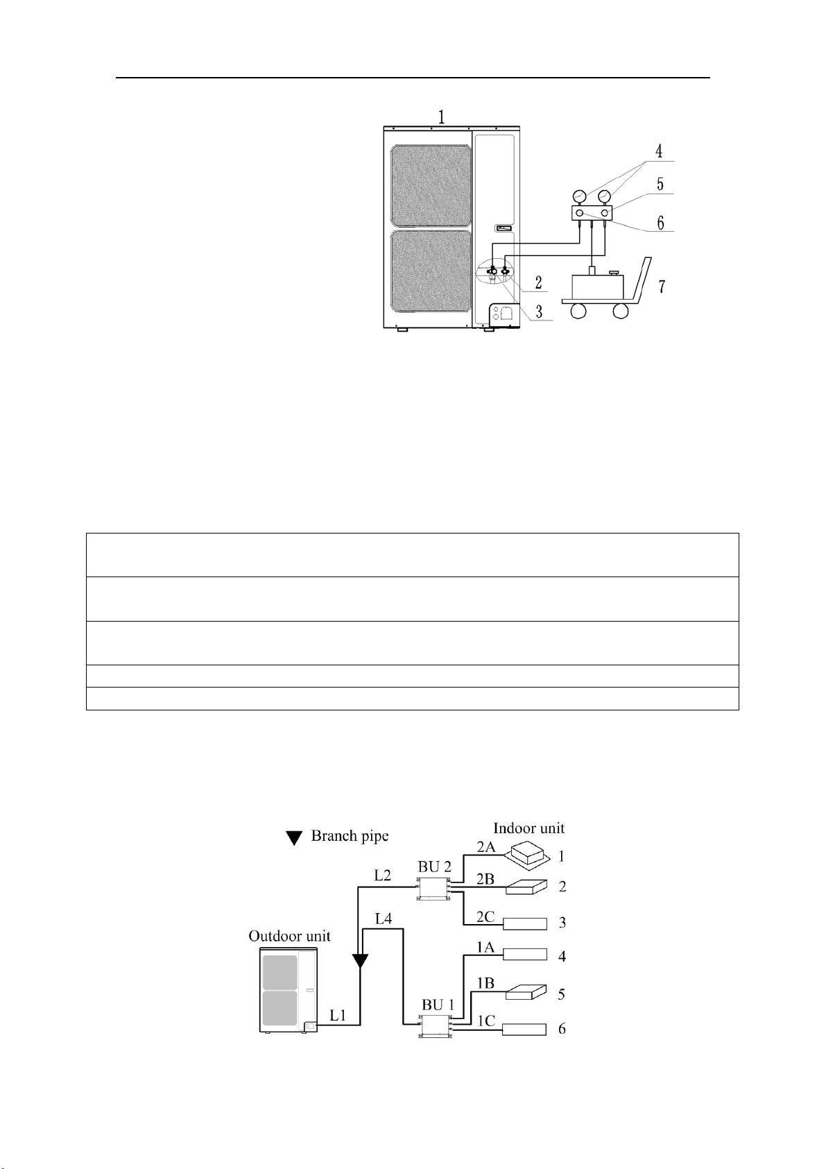
Super Free Match Series
14
one hour under the condition.
1: Outdoor unit
2: Liquid side stop valve
3: Gas side stop valve
4: Pressure-vacuum gauge
5: Hi-knob
6: Lo-knob
7: Vacuum pump
Fig. 17
5) Turn off the knobs firstly and then the pump, and if the pressure of the pressure-vacuum gauge
does not rise within 2 hours, the system is under a vacuum. Otherwise, the system has leaked,
please look for where the gas leaks in.
6.8 Refrigerant Charging
The refrigerant has been charged into the outdoor unit before shipped from the manufacturer,
while additional refrigerant still need be charged into the refrigerant pipe in the
field installation.
6.8.1 Calculation of the Additional Refrigerant Charging
1) Get the refrigerant charge of the outdoor unit from the nameplate.
NOTICE
1) The refrigerant charge of the outdoor unit does not include the charged additionally in the indoor unit,
BU module and the refrigerant pipe.
2) For the length of the connecting pipe is decided on the field, the amount of additional refrigerant shall
be decided depending on the dimension and the length of the liquid pipe used on the field.
3) It does not need to add refrigerant if the total length of liquid pipe is within 30m (98-3/8feet).
4) Record the amount of additional refrigerant for convenience of future maintenance.
2) Calculating the Mass of Additional Refrigerant
Additional Refrigerant Charge (kg/oz) = Σ the Liquid Pipe Length of Φ6.35 ×0.022kg/m (0.020oz/
inch)+Σ
the Liquid Pipe Length of Φ9.52×0.054kg/m (0.048oz/inch)-1.47kg(51.86oz) NOTICE!
If the additional refrigerant charge is negative, it does not need to add refrigerant.
3) Example: MULTIU48HP230V1BO
Fig. 18
Super Free Match Series
15
Table 6
Serial No. Model
Indoor unit 1 Cassette type GKH(12)BA-D3DNA2A/I
Indoor unit 2 Duct type GFH(09)EA-D3DNA1A/I
Indoor unit 3 Wall mounted type GWH09UB-D3DNA1A/I
Indoor unit 4 Wall mounted type GWH09MB-D3DNA3D/I
Indoor unit 5 Duct type GFH(09)EA-D3DNA1A/I
Indoor unit 6 Wall mounted type GWH09TB-D3DNA1A/I
Table 7
Serial Diameter(mm/inch) Length(m/feet)
L1 Φ9.52(3/8) 20(65-5/8)
L2 Φ9.52(3/8) 10(32-3/4)
L4 Φ9.52(3/8) 10(32-3/4)
1A Φ6.35(1/4) 5(16-3/8)
1B Φ6.35(1/4) 5(16-3/8)
1C Φ6.35(1/4) 5(16-3/8)
2A Φ6.35(1/4) 5(16-3/8)
2B Φ6.35(1/4) 5(16-3/8)
2C Φ6.35(1/4) 5(16-3/8)
The total length of the liquid pipes: 20+10+10+5+5+5+5+5+5=70m (229-5/8feet).
Thus, the total length is over than 30m (98-3/8feet), so the air conditioner needs to add refrigerant.
Additional refrigerant charge
Σ the Liquid Pipe Length of Φ6.35×0.022kg/m +Σ the Liquid Pipe Length of Φ9.52×0.054kg/m
-1.47kg
=(5+5+5+5+5+5)(m)×0.022kg/m+(20+10+10)(m)×0.054kg/m-1.47kg
=1.35kg (47.63oz)
4) Additional refrigerant charge record for future maintenance
Table 8
Diameter(mm) Total length(m/feet) Additional refrigerant charge(kg/oz)
Φ6.35(1/4)
Φ9.52(3/8)
Total
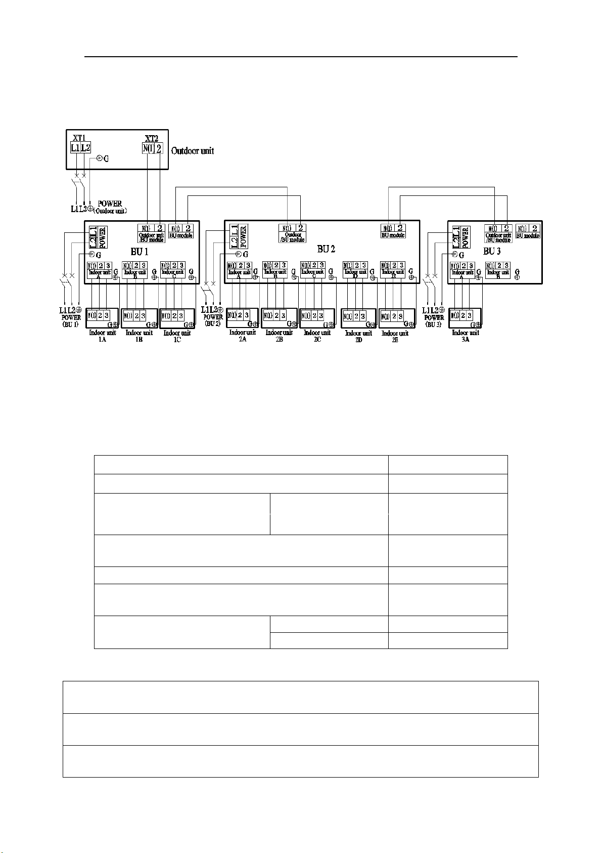
6.8.2 Procedures for adding refrigerant
Super Free Match Series
16
NO. 1 2 3 4 5
Name
Outdoor
unit
Service port
Liquid side stop
valve
Gas side stop
valve
Pressure-vacuum
gauge
NO. 6 7 8 9
Name Hi-knob Lo-knob R410A tank Scale
Fig. 19
1) When the liquid and gas stop valves have not been opened, the system is under the vacuum:
① Refer to the left of the figure above; connect the R410A tank to the system.
② Turn on the R410A tank and the Hi-knob; charge the R410A refrigerant into the unit from the
liquid side stop valve. The Lo-knob should be closed completely.
③ Turn off the R410A tank and the Hi-knob immediately, when the adding refrigerant is enough.
④ Turn on the liquid and gas side stop valves in an anticlockwise direction slowly and completely.
2) If the pressure of the system is too high to charge refrigerant, you can do as follow.
① Turn on the liquid and gas side stop valves in an anticlockwise direction slowly and completely.
② Turn on the power of the air conditioner, and set cooling mode, running more than 0.5h when
outside temperature is higher than 15℃(59℉) DB.
a) Refer to the left of the figure above; connect the R410A tank to the system.
b) Turn on the R410A tank and the Lo-knob; charge the R410A refrigerant into the unit from
the gas side stop valve. The Hi-knob should be closed completely.
c) Turn off the R410A tank and the Lo-knob immediately, when adding refrigerant is enough.
③ Turn on the power of the air conditioner, and set heating mode, running more than 0.5h when
outside temperature is lower than 15℃(59℉) DB.
a) Refer to the right of the figure above; connect the R410A tank to the system.
b) Turn on the R410A tank and the Hi-knob; charge the R410A refrigerant into the unit from
the service port. The Lo-knob should be closed completely.
c) Turn off the R410A tank and the Hi-knob immediately, when adding refrigerant is enough.
CAUTION
1) Make sure that the liquid and gas side stop valves are opened completely after the installation.
2) Make sure that the length of liquid pipe is exactly.
3) Additional refrigerant charge must be measured exactly.
4) Make sure that the refrigerant which charge into the unit is in liquid state.
5) Please prevent the refrigerant leakage away from your body when remove the charging hose.
6) Please heat the refrigerant tank with hot water or hot air when the outside temperature is too low.
However, it must be forbidden to heat with fire directly, otherwise it may lead to explosion.
Super Free Match Series
17
7 Electrical Wiring Work
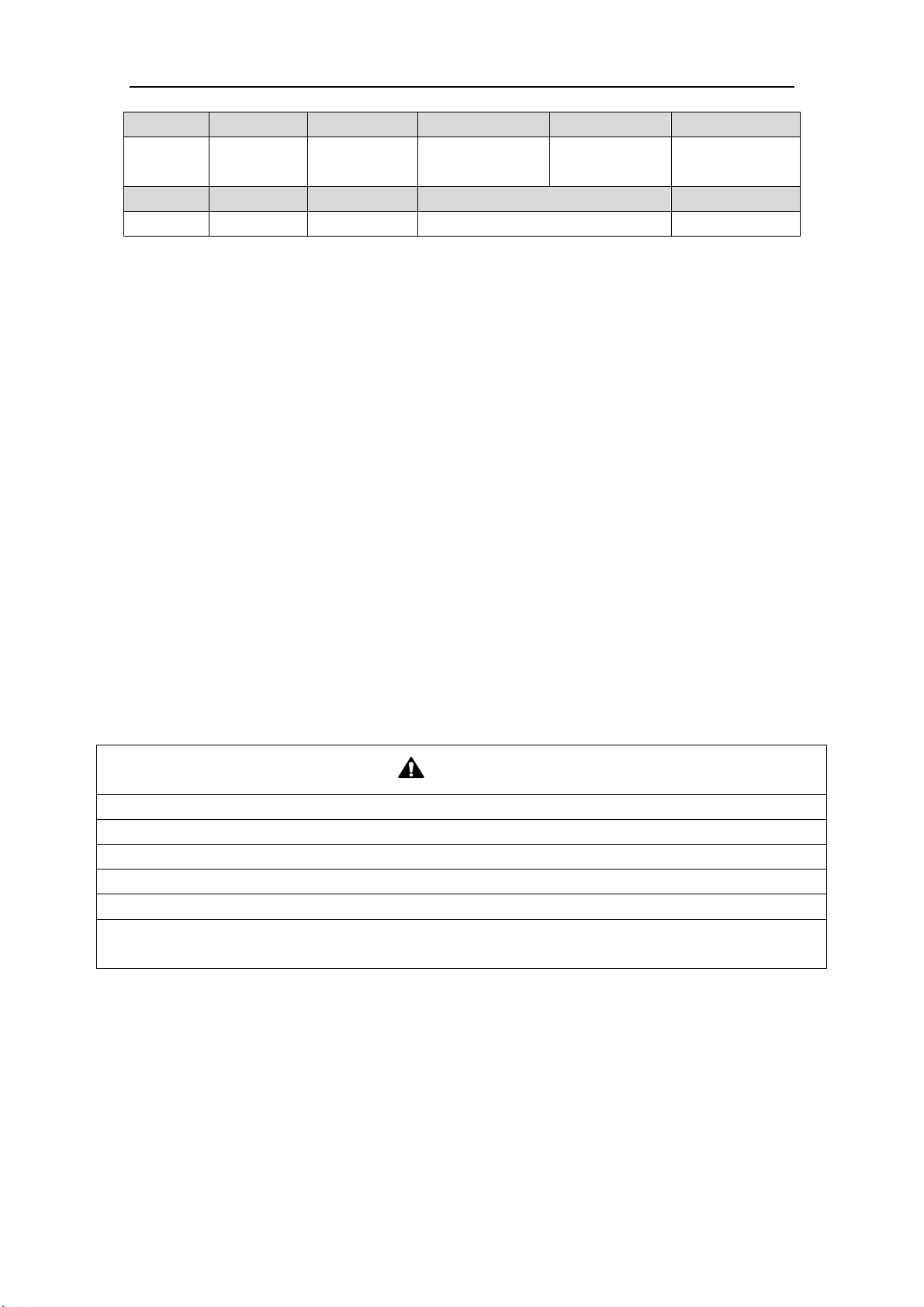
7.1 Wiring Connection
NOTICE! The “L1”, “3” terminals are connected to the live wire, the “L2”,”N(1)” terminals
are connected to the neutral wire and the ”2” terminal is connected to the transmission line.
Fig. 20
7.2 Requirements of Power Circuit and Cable
Table 9
zH06,hP1 ycneuqerf dna esahP
V032/802 egatloV
Recommended cable of outdoor unit
(Pieces × Sectional area)
MULTIU48HP230V1BO
3×6.0 mm
2
Recommended cable of BU module
(Pieces × Sectional area)
3×0.75 mm
2
Transmission line (Pieces × Sectional area) 2×1.5 mm
2
Recommended cable of indoor unit
(Pieces × Sectional area)
4×0.75mm
2
Capacity of the air switch
MULTIU48HP230V1BO
50A
BU module 10A
NOTICE
1) The total length of the transmission line between the outdoor unit and the furthest BU module is not
more than 55m (180feet). Otherwise, the system cannot work possibility.
2) The specifications of the power cable and transmission line listed in the table above are determined
based on the maximum power (maximum amps) of the unit.
Super Free Match Series
18
3) The specifications of the power cable listed in the table above are applied to the conduit-guarded
multi-wire copper cable (like, YJV copper cable, consisting of PE insulated wires and a PVC cable
jacket) used at 40℃(104℉) and resistible to 90℃(194℉), and shall be at least those of ordinary
polychloroprene sheathed cords. If the working condition changes, they should be modified according
to the related national standard.
4) The specifications of the air switch listed in the table above are applied to the breaker with the working
temperature at 40℃(104℉). If the working condition changes, they should be modified according to the
related national standard.
5) The length of the recommended power cable should be less than 15meters (49feet); otherwise, the
diameter of the power cable is not enough.
6) Mentioned power cable and transmission line length is just a reference value. It may be different
depending on the condition of installation, humidity or materials, etc.
7) An all-pole disconnection switch having a contact separation of at least 3mm in all poles should be
connected in fixed wiring.
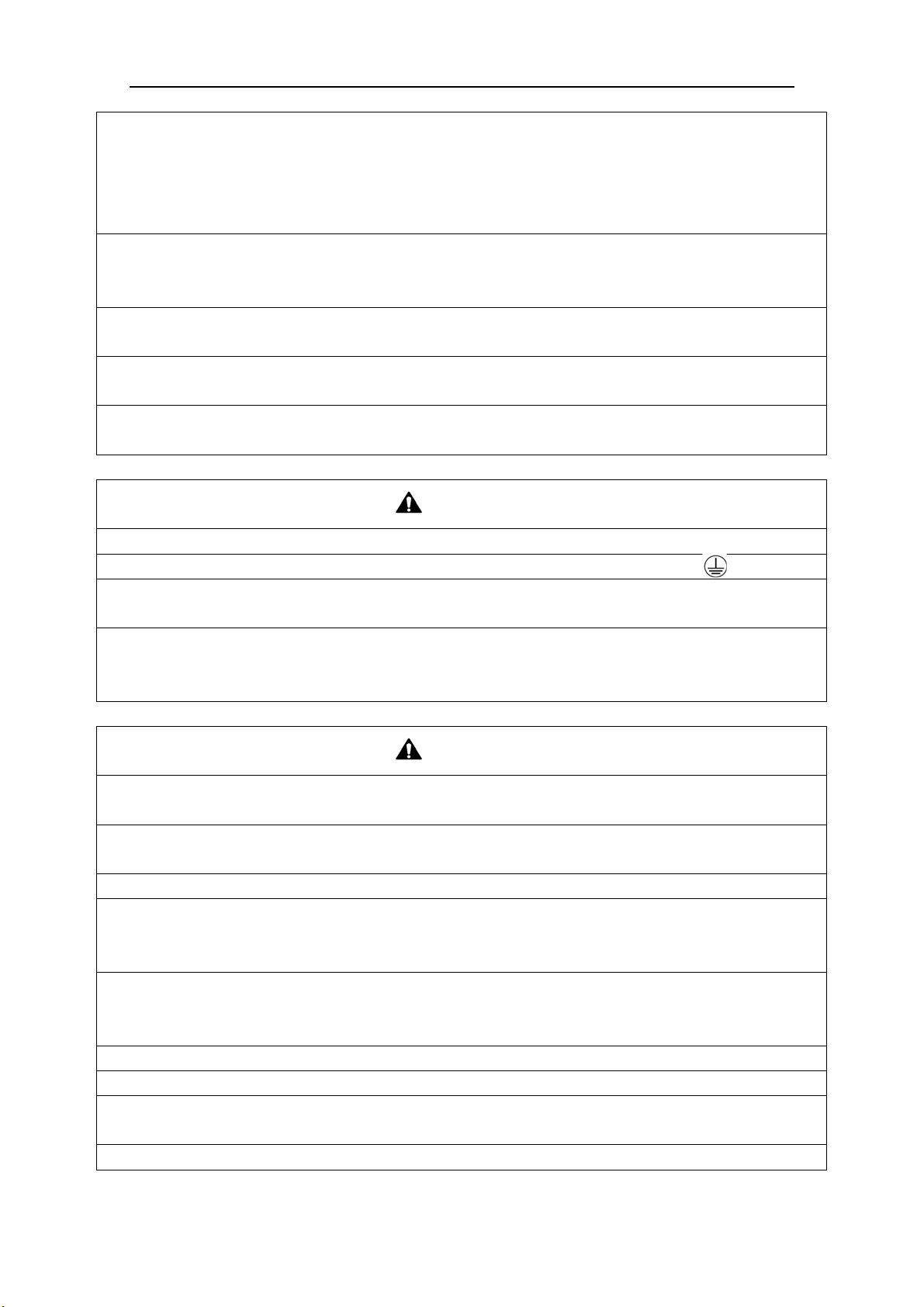
7.3 Ground Requirements
WAR NI NG
1) The air conditioner is classified into the Class I appliances, so its ground ways must be reliable.
2) The ground wire must be fixed on the screw hole with the sign as the right figure.
3) The yellow-green wire of the air conditioner is the ground wire and must be fixed by the tapping screw.
And it cannot be used for other purpose or cut off. Otherwise, it will cause the hazard of electric shock.
4) The reliable ground terminal should be provided and the ground wire cannot be connected to any of the
following places: a. Water pipe; b. Coal gas pipe; c. Sewage pipe; d. Lightning rod
e. Telephone line f. Other unreliable places considered by a professional.
7.4 Precautions on the Electrical Wiring Work
WAR NI NG
1) The electrical installation should be carried out by the professional as instructed by the local laws,
regulations and also this manual.
2) The ground connection should be reliable and the ground wire should be connected to the dedicated
device of the building by the professional.
3) Before starting work, the power must not be supplied to the unit.
4) The air switch coupled with the leakage current protection switch must be equipped in the circuits,
which is of enough capacity and of both magnetic and thermal tripping functions in case of the short
circuit and overload.
5) The electrical work should use a cable length enough to cover the entire distance with no connection. If
it is unavoidable, please make sure the connection should be reliable, the external forces will not act on
the wires and the joint is not bared. Otherwise it will cause electrical shock or fire etc.
6) The power cable with the rated voltage and exclusive circuit for the air conditioner should be used.
7) Do not pull the power cable by force after it is installed.
8) The diameter of the power cable should be large enough and once it is damaged, it must be replaced by
the dedicated one.
9) The multi-wire copper cable should be used for the power cable and the transmission line.
Super Free Match Series
19
7.5 Precaution of Laying Wires
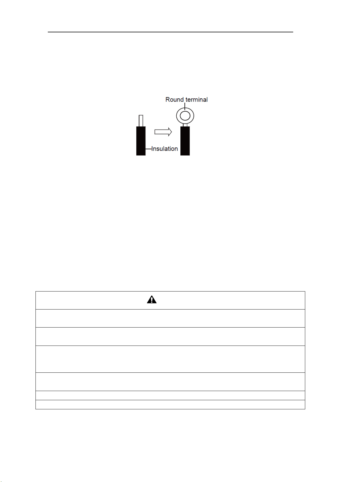
1) Use a wire stripper to strip off a length of the insulation layer at the end of the wires;
2) Loosen the screws on the terminal block of the air conditioner;
3) Press the ends of the cable tightly onto the round terminals corresponding to the size of the
screws.
4) Pass the screw through the round terminals and fix it onto the terminal block.
Fig. 21
7.6 Procedures for Electrical Wiring Work
1) Knock the holes in the plate of the chosen direction with the hammer.
2) Place the rubber ring on the knockout hole.
3) Let the power cable and transmission line go through the knockout hole.
4) Connect the power cable of the outdoor unit to the L1, L2 terminals with the sign of the XT1
and as well as the ground screw.
5) Connect the transmission line of the outdoor unit to the N(1), 2 terminals with the sign of the
XT2.
6) Fix the power cable and transmission line firmly by cable fixing clip. In order to protect the
power cable and transmission line from damage by the pipes or others, an interval of at least
2cm (3/4inch) away is essential.
7) Screw the coping plate, front side plate, right connection board, front connection board back.
8) Cover the through-holes with sealing materials to prevent the water, dust or small animals going
into the outdoor unit.
CAUTION
1) The transmission line and the power cable must be separated with an interval of at least 2cm (3/4inch);
otherwise it may be result in communication problem.
2) In order to protect the power cable and transmission line from damaging by the knockout hole, the
rubber ring must be placed on the hole. Otherwise, it may cause electrical shock or fire etc.
3) The power wire and transmission line must be more than 1 meter (3-1/4feet) away from televisions or
radios which can emit electromagnetic waves to prevent image interference or noise. Otherwise, the unit
maybe cannot work.
4) Confirm the each cable connected to the terminal screw is exactly and securely after finishing the
electric work.
5) Fix each ground wire separately with the ground screw.
6) If the connecting wire is connected to the terminal incorrectly, it may cause a fire.
Super Free Match Series
20
8 Design of Drainage Pipeline
8.1 Installation of Drain Hose
1) Choose one drain hole in the bottom of the outdoor unit.
2) Connect the drain hose to the drain hole.
3) The drain hose should be kept at 5~10 degrees of gradient to facilitate discharge of the
condensing water. Take care that does not exert too much force on the hose.
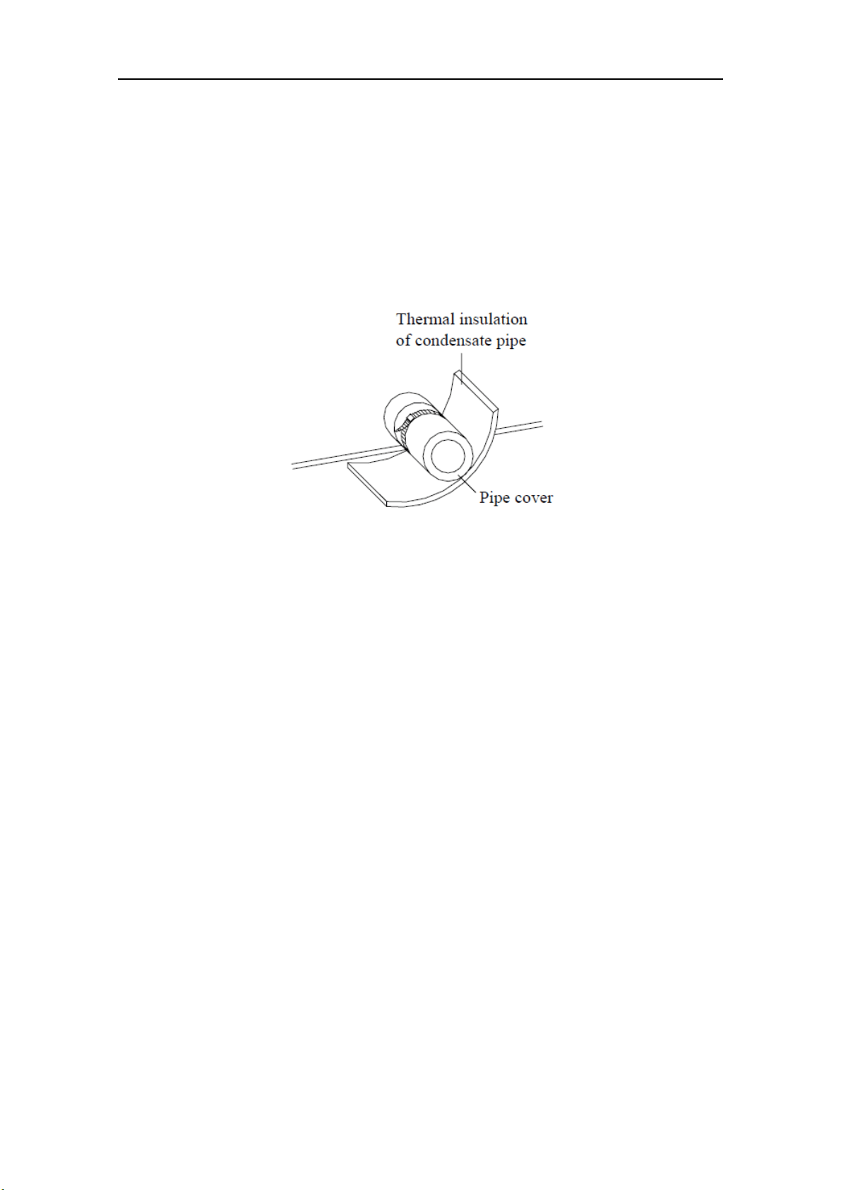
4) Thermal insulation materials should be placed at the joints of the drain hose so as to prevent
from dew condensation. Fix the drain hose firmly by binding band.
Fig. 22
5) The end of the drain hose should be inserted into the hole of drainage pipeline.
8.2 Design of Drainage Pipeline
1) The drainage pipeline should be kept at a certain gradient (1/50—1/100) so as to avoid bulges
of pipes where there might be water bends.
2) The drainage pipeline is form of the hard PVC pipes for common purposes which can be
purchased locally. The diameter of the PVC pipes is not less than 17mm (11/16inch) and the
pipeline should be fixed as close to the BU module as possible.
3) Insert the drain hose into the drain hole of drainage pipeline. Use binding band to fix it tightly.
It is not allowed to use adhesive glue to join the drain hose to the drainage hole.
4) When the drainage pipeline is laid for a couple of units, the position of the shared pipeline
should be approximately 100mm lower than the drainage hole of each module. In this case,
some special-purpose pipes with thicker walls will be used.
NOTICE! At intervals of about 1 meter (3-1/4feet), fix the drain pipes to the wall with
brackets, not floating in the air.
Super Free Match Series
21
9 Installation of Protective Layer
1) The refrigerant pipes should be insulated by the heat insulation material and plastic tape in
order to prevent water condensation and leakage.
2) Do not use the foam on the branch pipe as the material for heat insulation, heat insulation
material of branches should be the same as that of the pipeline.
NOTICE! The heat resistance of heat insulation material should be over than 120℃(248℉)
and its thickness is more than 9mm(3/8inch).
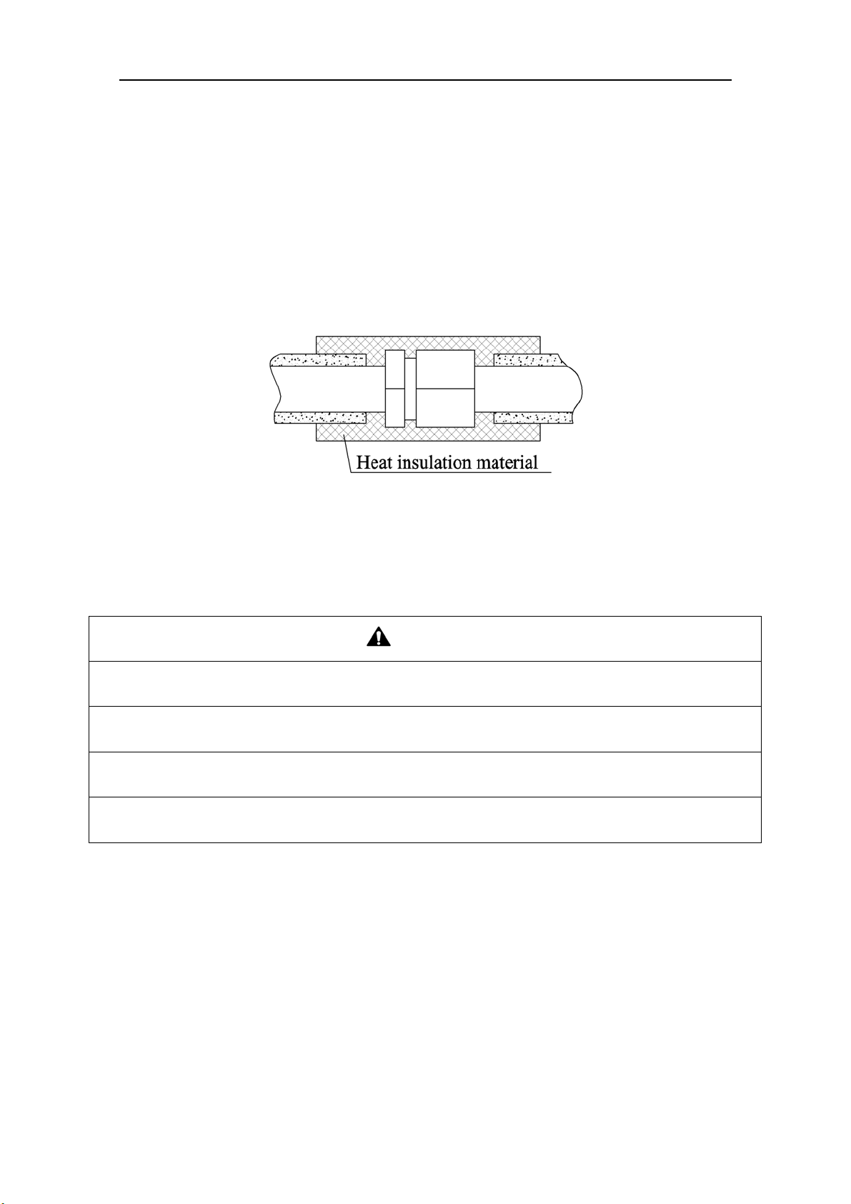
3) The joints of the system should be wrapped with the heat insulation material and no gap is
allowed on the joint of the system, as shown in the following figure.
Fig. 23
4) Bundle the refrigerant pipe and transmission line together with tape, and separate them from the
drain pipe to prevent the condensate water overflowing.
5) Wrap the pipe from the bottom of the outdoor unit to the top of the pipe where it enters the wall.
During the wrapping, the later circle should cover half of the former one.
CAUTION
1) At intervals of about 1 meter (3-1/4feet), fix the refrigerant pipes to the wall with brackets, that is, don’t
let the unit withstand the weight of it or float it in the air.
2) After the pipe is protected well enough, never bend it to form a small angle(<90°), otherwise it would
crack or break.
3) Do not wrap the refrigerant pipes very tight, otherwise the insulation effect would be weakened.
Additionally, make sure the drain hose is separated from the refrigerant pipes.
4) After that, cover the hole on the wall with sealing materials to prevent wind and noise going into the
room.
Super Free Match Series
22
10 Test Operation
10.1 Check after Installation
Table 10
Items to be checked Possible malfunction
Has it been fixed reliable? The unit may drop, vibrate or make noise.
Has the gas leakage been checked? It may cause insufficient cooling(heating) capacity.
Is the thermal insulation of the unit sufficient? It may cause condensation and dripping.
Is the drainage well? It may cause condensation and dripping.
Is the voltage in accordance with the rated
voltage marked on the nameplate?
It may cause electric malfunction or the
components may be burned out
Are the lines and pipelines correctly installed?
It may cause electric malfunction or the
components may be burned out
Has the unit been safely grounded? It may cause electrical leakage.
Are the models of lines in conformity with
requirements?
It may cause electric malfunction or the
components may be burned out
Are there any obstacles near the air inlet and
outlet of the indoor and outdoor units?
It may cause insufficient cooling(heating) capacity.
Have the length of connection pipes and
refrigerant charge amount been recorded?
It is not easy to decide the charge amount of
refrigerant.
10.2 Test Operation
1) Before test operation
The appearance of the unit and the refrigerant pipes cannot be damaged during the installation.
Do not switch on power before installation is finished completely.
Electrical wiring must be connected correctly and securely.
The stop valves of the outdoor unit should be opened fully.
All the impurities such as scraps and thrums must be cleared from the unit.
2) Test operation method
① The test operation should be carried out by the professionally skilled personnel on the premise
that all items listed above are in normal conditions.
② Set the status of the power supply switch as “ON” eight hours before the start of operation
③ Press mode button, to select the COOL, or HEAT. Whether the air conditioner is work
normally or not.
The fan motor of the indoor unit will run automatically in one minute.
The fan motor and compressor of the outdoor unit will run automatically in one minute.
④ Make sure that every combination of indoor units can work well.
WAR NI NG
If the unit cannot work nor has any abnormal noise after the compressor is started, turn off the unit for an
immediate check.
Super Free Match Series
23
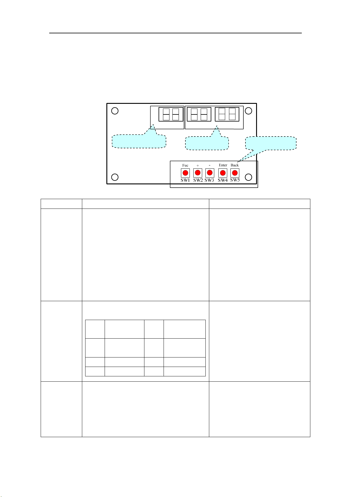
11 Testing Board Introduction
11.1 Compose of the Testing Board
The testing board is in front of electrical box and can be observed well. It has several following
advantages: detect indoor unit numbers and indoor unit address, displays real running function and
error code automatically. It is composed of the function section, data section and button section.
11.2 Instruction of Function and Data Section
Running state The display of function section The display of data section
Stop
① The section will display the numbers of the
indoor units which have established
communication with the outdoor unit. For
example, if there are seven established indoor
units, the section will display “7”.
② It will display the address of the indoor units
by turns. For example, the “1b” is represented
of the indoor unit 1B.
(BU module:1/2/3,Indoor unit: A/b/C/d/E)
① If the function section displays the
numbers of the indoor units, the data
section will display the outside
temperature. For example, the “35” is
represented of 35℃.
② If the function section displays the
address of the indoor unit,the data
section will display the model of the
indoor unit, for example, the “35” is
represented of 35 model.
Normal
The code of running state:
Code
Running
state
Code Running state
UE
Pressure
equalization
UH Heating
UP Pump down F7 Oil returning
UC Cooling H1 Defrosting
It displays the target gear of the
compressor. If the gear is zero, it will
display “0”. For example, the gear is
the fifteenth; it will display “15”. The
range of the gear is from 0 to 60.
Malfunction
If the malfunction occurs in the system, the
section will display the error code. If there are
several malfunctions, it will display the error
codes by turns at intervals of 2 seconds.
① If the malfunction occurs in the
outdoor unit, the section displays
nothing;
② If the malfunction occurs in the
indoor units, the section displays the
address of the indoor unit.
Function section
Data section Button section
Super Free Match Series
24
12 Troubleshooting
WAR NI NG
1) In the event of abnormal conditions (like, stinky smell), please shut off the power supply immediately
and then contact the appointed service center; otherwise, the abnormal running would damage the air
conditioner and also would cause electric shock or fire hazard .
2) Do not repair the air conditioning personally but instead contact the professionally skilled personnel at
the appointed service center, as the incorrect repair would cause electric shock or fire hazard etc.
12.1 Check before Contacting Service Center
Please check the following items before contacting the maintenance serviceman.
Conditions Causes Corrective actions
The unit does not
run at all
Broken fuse or breaker is off
Replace the damaged fuse or
close the breaker
Power off
Restart the unit after power
supply resumes
Power supply plug is loose Plug the power supply properly
The batteries voltage of the remote
controller is insufficient
Replace with new batteries
Remote controller is out of the control
scope
The distance shall be within 8m
The unit stops
soon after it starts
Air inlet or outlet of indoor unit or
outdoor unit is blocked
Remove the obstacles
Cooling or heating
is abnormal
Air inlet or outlet of indoor unit or
outdoor unit is blocked
Remove the obstacles
Temperature setting is improper
Adjust the setting of remote
controller or wire controller
Air speed is set too low
Adjust the setting of remote
controller or wire controller
Improper airflow direction
Adjust the setting of remote
controller or wire controller
Door or window is open Close the door or window
Under direct sunshine
Hang curtain or blinders over the
window
Too many people in the room
Too many heat sources indoors Reduce the heat sources
The filter screen is dirt or blocked Clean the filter screen
NOTICE! If the air conditioner still runs abnormally after the above check and handling,
please contact the local appointed service center and also give a description of the error
occurred as well as the model of the unit.
Super Free Match Series
25
12.2 Problem Handling
The conditions listed below are not classified into errors.
sesuaC snoitidnoC
The unit does
not run
When restart the unit soon after
it is stopped
The overload protection switch of the unit let
the startup delayed for three minutes
As soon as power supply is on
The unit will stand by for approximate one
minute
The unit blows
out mist
When the cooling operation
starts
The hi-humidity air indoor is cooled quickly
The unit
generates noise
The unit “clatters” as soon as it
starts running
It is the sound generated during the
initialization of the electronic expansion
valve
The unit “swishes” during the
cooling operation
It is the sound when the refrigerant gas runs
inside the unit
The unit “swishes” when it is
started or stopped
It is the sound when the refrigerant gas stops
running
The unit “swishes” when it is in
and after the running
It is the sound when the draining system is
operating
The unit “squeaks” when it is in
and after the running
It is the sound of frication generated by the
skin plate etc which swells due to the
temperature change
The unit blows
out dust
When the unit restarts after it is
not used for a long time
The dust inside the unit is blown out again
The unit emits
odors
When the unit is running The odors absorbed in are blown out
12.3 Error Description
If some error occurs when the unit is running, the error code will be displayed and check for
more details about the meaning of each error.
Errors of definition
Main control display for outdoor unit
Indoor
unit code
Testing
board code
Yellow LED Red LED Green LED
The compressor is startup Flash 1 time
IPM current protection Flash 3 times
H5 H5
IPM temperature protection Flash 5 times
P8 P8
PFC current protection Flash 7 times
HC
PFC temperature protection Flash 8 times
P8 P8
Low voltage protection Flash 9 times
PL PL
High voltage protection Flash 10 times
PH PH
Low pressure protection Flash 11 times
E3
High pressure protection Flash 12 times
E8
High pressure switch protection Flash 13 times
E1
Capacitor charging error Flash 14 times
PU
AC current protection Flash 15 times
E5 E5
E3
E8
E1
Super Free Match Series
26
Memory card error Flash 16 times
EE
Compressor demagnetizing
protection
Flash 17 times
HE HE
Compressor desynchronizing Flash 18 times
H7 H7
Compressor phase lack Flash 19 times
U2 U2
Compressor phase circuit detection
error
Flash 20 times
U1 U1
Compressor power protection Flash 21 times
L9 L9
Compressor discharge temperature
protection
Flash 23 times
E4 E4
Lack of refrigerant or jam protection Flash 31 times
F0 F0
Normal operation Flash 1 time
Frequency limitation for AC current Flash 2 times
F8
Oil returning Flash 3 times
F7
Defrosting Flash 4 times
H1 H1
Frequency limitation for IPM
temperature
Flash 5 times
EU
Frequency limitation for PFC
temperature
Flash 6 times
EU
Frequency limitation for compressor
overload
Flash 8 times
LU
Frequency limitation for compressor
discharge temperature
Flash 9 times
F9
Frequency limitation for low pressure Flash 10 times
Pn
Frequency limitation for high
pressure
Flash 11 times
F6
Discharge temperature sensor error Flash 12 times
F5 F5
Outdoor temperature sensor error Flash 13 times
F3 F3
Suction temperature sensor error Flash 15 times
dc
Condenser temperature sensor error Flash 16 times
A7 A7
Low pressure sensor error Flash 18 times
dL
High pressure sensor error Flash 19 times
e1
Fan motor error for indoor unit Flash 20 times
H6 H6
Driving board is connected Flash 1 time
Testing board is connected Flash 2 times
Computer is connected Flash 4 times
Indoor unit 1 is connected Flash 5 times
Indoor unit 2 is connected Flash 6 times
Indoor unit 3 is connected Flash 7 times
Indoor unit 4 is connected Flash 8 times
Indoor unit 5 is connected Flash 9 times
Middle pressure sensor error
FU
Intermediate vapor injection
temperature sensor error
Fb
Super Free Match Series
27
Indoor unit 6 is connected Flash 10 times
Indoor unit 7 is connected Flash 11 times
Indoor unit 8 is connected Flash 12 times
Indoor unit 9 is connected Flash 13 times
Indoor unit anti-freeze protection
E2 E2
Indoor temperature sensor error
F1 F1
Indoor evaporator midway
temperature sensor error
F2 F2
Temperature sensor error for liquid
pipe of BU module
b5 b5
Temperature sensor error for gas pipe
of BU module
b7 b7
Running mode conflicts
E7 E7
Communication error
E6
E6
indoor
unit address
Communication error between the
main board and driving board
P6
Communication error between the
main board and testing board
CE
Gas sensor error of indoor unit
Fn
Humidity sensor error of indoor unit
L1
Water full error of indoor unit
E9 E9
Jumper terminal error of indoor unit
C5 C5
Phase lack of power supply
dJ
Fan motor error of outdoor unit
L3
Refrigerant recovery mode
Fo Fo
Display mode of Red LED and Yellow LED: At intervals of half a second, flash for half a
second; if there are several malfunctions, it will display the error codes by turns at intervals of
one second.
Display mode of Green LED: At intervals of 1/4 second, flash for 1/4 second; and it displays
the running states by turns at intervals of half a second.

Super Free Match Series
28
13 Maintenance
Check, maintenance and care regularly should be performed by professional personnel, which
will prolong the unit service life.
13.1 Outdoor Condenser
Outdoor condenser is required to be cleaned every two months. Use vacuum cleaner with nylon
brush to clean up dust and sundries on the surface of condenser. Blow away dust by compressed air
if it is available. Never use water to wash the condenser.
13.2 Drain Pipe
In order to drain condensate smoothly, please check the drain pipe regularly is clogged or not.
13.3 Check before the Seasonal Use
Check the air inlet and outlet of the indoor and outdoor units to confirm there is no blockage.
Check the ground wire to confirm the grounding is reliable.
Check the batteries of the wireless remote controller to ensure that they have been replaced.
Check the filter screen that it has been set soundly.
If the air-conditioning unit shall be operated again after a long-term shut off, set the status of
the power supply switch as “ON” eight hours before the start of operation, so as to ensure the
successful startup of the air-conditioning unit.
Check the outdoor unit to ensure the installation of it is steady. Contact the appointed service
center if there is any abnormal condition.
13.4 Maintenance after Seasonal Use
Turn off the power supply of the air conditioning unit and set the status of the power supply
switch as “OFF”.
Clean the filter screen and the housing of the indoor and outdoor units.
Remove the dust and the foreign matters of the outdoor unit.
In the event of rusting, please use the anti-rust paint to stop spreading of rust.
Refer to the Installation and Operation Manual of each indoor unit respectively for detailed
maintenance.
14 After-sales Service
If the unit cannot work or has any problem, please contact the local after-sales service agency
designated by Gree.
Warranty should meet the following requirements:
① The installation and test operation of the unit should be operated by professional personnel from
appointed service center.
② Only Gree manufactured accessories can be used on the machine.
③ All the instructions listed in this manual should be followed.
④ Warranty will be automatically invalid if fails to obey any item mentioned above.


GREE ELECTRIC APPLIANCES, INC. OF ZHUHAI
Add: West Jinji Rd, Qianshan, Zhuhai, Guangdong, China, 519070
Tel: (+86-756) 8522218 Fax: (+86-756) 8669426
E-mail: [email protected] www.gree.com
CAT NO: GREE_MULTIU_INSTALL & OWNERS_48MBH_03112020