

*(
*($SSOLDQFHVFRP
:ULWHWKHPRGHODQGVHULDO
QXPEHUVKHUH
0RGHOBBBBBBBBBBBBBBBB
6HULDO BBBBBBBBBBBBBBBB
<RXFDQILQGWKHPRQDODEHO
EHKLQGWKHGUDZHURUEHKLQGWKH
ORZHURYHQGRRURQWKHIURQWRI
WKHUDQJHIUDPH
4XLFN6HW9
4XLFN6HW9,
2ZQHU·V0DQXDO
5DQJHV
6DIHW\,QVWUXFWLRQV²
2SHUDWLQJ,QVWUXFWLRQV
.LWFKHQ7LPHU
2YHQ²
$GMXVW2YHQ7KHUPRVWDW
%DNLQJRU5RDVWLQJ
%URLOLQJ%URLOLQJ*XLGH
&RQWUROV
&RQYHFWLRQ2YHQ
3UHKHDWLQJ
3UREH
6DEEDWK)HDWXUH
6HOI&OHDQLQJ
3URRILQJDQG:DUPLQJ)HDWXUHV
6SHFLDO)HDWXUHV
7LPHG%DNLQJDQG5RDVWLQJ
6XUIDFH8QLWV²
%ULGJH%XUQHU
&RRNZDUH
*ODVV&RRNWRS
:DUPLQJ=RQH
&DUHDQG&OHDQLQJ
$OXPLQXP)RLO
&RQWURO.QREV
&RQWURO3DQHO
*ODVV&RRNWRS
/LIW2II2YHQ'RRU
/LJKW
2YHQ)ORRU
2YHQ+HDWLQJ(OHPHQWV
5DFNV
6WRUDJH'UDZHU
6XUIDFHV
9HQW
7URXEOHVKRRWLQJ7LSV
$FFHVVRULHV
&RQVXPHU6XSSRUW
&RQVXPHU6XSSRUW%DFN&RYHU
:DUUDQW\
3ULQWHGRQ
5HF\FOHG3DSHU
)UHH6WDQGLQJ6OLGH,QDQG'URS,Q(OHFWULF
,Q&DQDGD
ZZZ*($SSOLDQFHVFD
(VSDxRO
)RUD6SDQLVKYHUVLRQRIWKLVPDQXDOYLVLW
RXU:HEVLWHDW*($SSOLDQFHVFRP
3DUDFRQVXOWDUXQDYHUVLRQHQHVSDxRO
GHHVWHPDQXDOGHLQVWUXFFLRQHVYLVLWH
QXHVWURVLWLRGHLQWHUQHW
*($SSOLDQFHVFRP
3ULQWHGLQWKH8QLWHG6WDWHV
5HDGDOOVDIHW\LQVWUXFWLRQVEHIRUHXVLQJWKHSURGXFW)DLOXUHWRIROORZWKHVHLQVWUXFWLRQVPD\UHVXOWLQILUHHOHFWULFVKRFN
VHULRXVLQMXU\RUGHDWK
,03257$176$)(7<127,&(
7KH&DOLIRUQLD6DIH'ULQNLQJ:DWHUDQG7R[LF(QIRUFHPHQW$FWUHTXLUHVWKH*RYHUQRURI&DOLIRUQLDWRSXEOLVKDOLVWRIVXEVWDQFHV
NQRZQWRWKHVWDWHWRFDXVHFDQFHUELUWKGHIHFWVRURWKHUUHSURGXFWLYHKDUPDQGUHTXLUHVEXVLQHVVHVWRZDUQFXVWRPHUVRISRWHQWLDO
H[SRVXUHWRVXFKVXEVWDQFHV
7KHILEHUJODVVLQVXODWLRQLQVHOIFOHDQRYHQVJLYHVRIIDYHU\VPDOODPRXQWRIFDUERQPRQR[LGHGXULQJWKHFOHDQLQJF\FOH([SRVXUHFDQ
EHPLQLPL]HGE\YHQWLQJZLWKDQRSHQZLQGRZRUXVLQJDYHQWLODWLRQIDQRUKRRG
,03257$176$)(7<,1)250$7,21
5($'$//,16758&7,216%()25(86,1*
$17,7,3'(9,&(
:$51,1*
:$51,1*
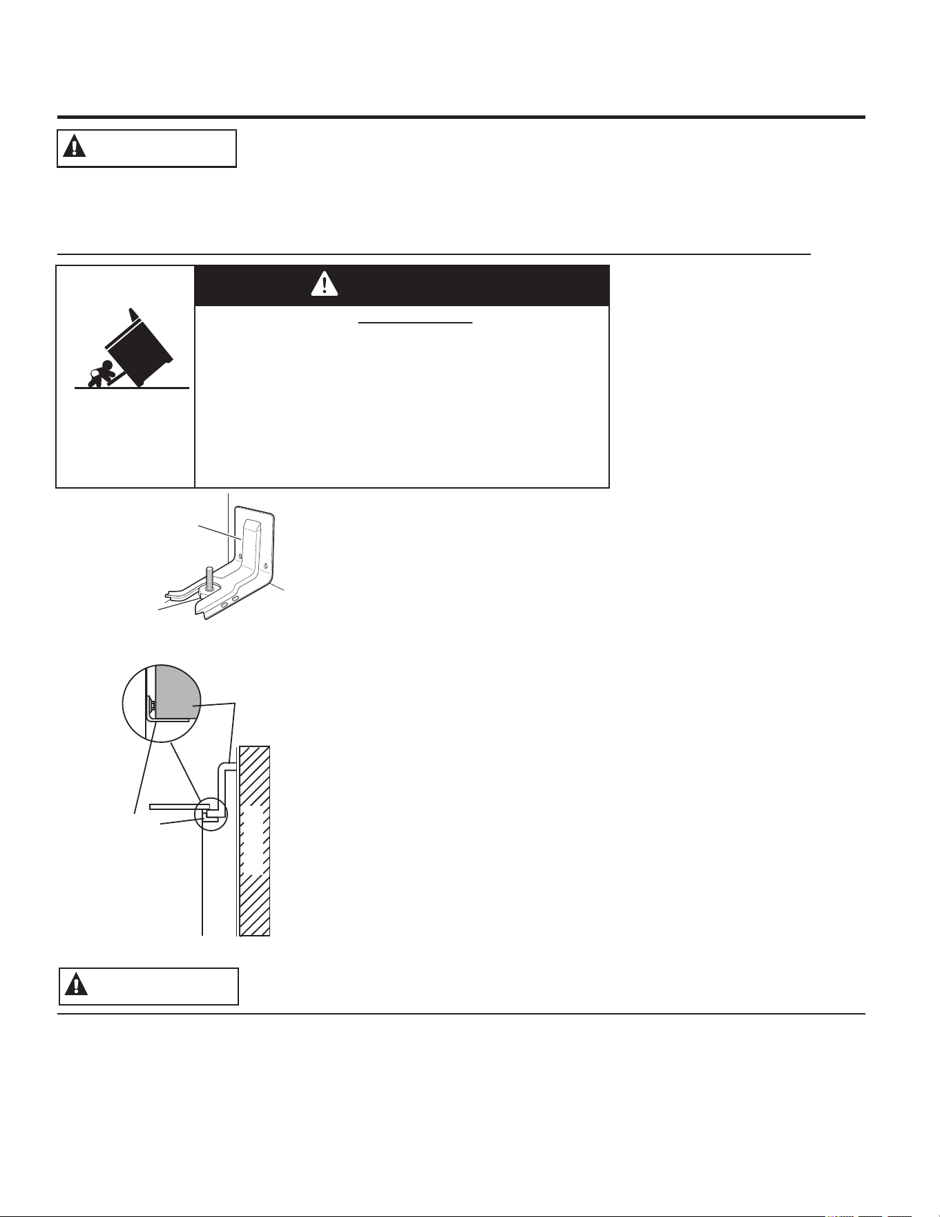
7RUHGXFHWKHULVNRIWLSSLQJWKH
UDQJHWKHUDQJHPXVWEHVHFXUHG
E\DSURSHUO\LQVWDOOHGDQWLWLS
EUDFNHW6HHLQVWDOODWLRQLQVWUXFWLRQV
VKLSSHGZLWKWKHEUDFNHWIRU
FRPSOHWHGHWDLOVEHIRUHDWWHPSWLQJ
WRLQVWDOO
)RU)UHHVWDQGLQJDQG6OLGH,Q
5DQJHV
7RFKHFNLIWKHEUDFNHWLVLQVWDOOHG
DQGHQJDJHGSURSHUO\ORRN
XQGHUQHDWKWKHUDQJHWRVHHWKDW
WKHUHDUOHYHOLQJOHJLVHQJDJHGLQ
WKHEUDFNHW2QVRPHPRGHOVWKHVWRUDJHGUDZHURUNLFNSDQHOFDQEH
UHPRYHGIRUHDV\LQVSHFWLRQ,IYLVXDOLQVSHFWLRQLVQRWSRVVLEOHVOLGHWKH
UDQJHIRUZDUGFRQILUPWKHDQWLWLSEUDFNHWLVVHFXUHO\DWWDFKHGWRWKHIORRU
RUZDOODQGVOLGHWKHUDQJHEDFNVRWKHUHDUOHYHOLQJOHJLVXQGHUWKHDQWLWLS
EUDFNHW
,IWKHUDQJHLVSXOOHGIURPWKHZDOOIRUDQ\UHDVRQDOZD\VUHSHDWWKLV
SURFHGXUHWRYHULI\WKHUDQJHLVSURSHUO\VHFXUHGE\WKHDQWLWLSEUDFNHW
1HYHUFRPSOHWHO\UHPRYHWKHOHYHOLQJOHJVRUWKHUDQJHZLOOQRWEHVHFXUHG
WRWKHDQWLWLSGHYLFHSURSHUO\
)RU'URS,Q5DQJHV
7RFKHFNLIWKHEUDFNHWLVLQVWDOOHGDQGHQJDJHGSURSHUO\VOLGHWKHUDQJH
IRUZDUGFRQILUPWKHDQWLWLSEUDFNHWLVVHFXUHO\DWWDFKHGWRWKHUHDURIWKH
UDQJHDQGVOLGHWKHUDQJHEDFNVRWKDWWKHDQWLWLSEUDFNHWVOLGHVMXVWXQGHU
WKHFRXQWHUWRSRUZRRGEORFNDWWDFKHGWRWKHUHDUZDOO
,I\RXGLGQRWUHFHLYHDQDQWLWLSEUDFNHWZLWK\RXUSXUFKDVHFDOO
WRUHFHLYHRQHDWQRFRVWLQ&DQDGDFDOO
)RULQVWDOODWLRQLQVWUXFWLRQVRIWKHEUDFNHWYLVLW*($SSOLDQFHVFRPLQ
&DQDGD*($SSOLDQFHVFD
Rear Wall
Oven
Anti-Tip
Bracket
Countertop or
Wood Block
)UHHVWDQGLQJDQG6OLGH,Q5DQJHV
'URS,Q5DQJHV
$QWL7LS
%UDFNHW
/HYHOLQJ/HJ
A child or adult can tip the range and be killed.
Verify the anti-tip bracket has been properly installed
and engaged.
Ensure the anti-tip bracket is re-engaged when the range
is moved.
Do not operate the range without the anti-tip bracket in
place and engaged.
Failure to follow these instructions can result in death or
serious burns to children or adults.
Tip-Over Hazard
WARNING
8VHWKLVDSSOLDQFHIRULWVLQWHQGHGSXUSRVHDVGHVFULEHGLQWKLV
2ZQHU·V0DQXDO
%HVXUH\RXUDSSOLDQFHLVSURSHUO\LQVWDOOHGDQGJURXQGHGE\D
TXDOLILHGLQVWDOOHULQDFFRUGDQFHZLWKWKHSURYLGHGLQVWDOODWLRQ
LQVWUXFWLRQV
'RQRWDWWHPSWWRUHSDLURUUHSODFHDQ\SDUWRI\RXUUDQJHXQOHVV
LWLVVSHFLILFDOO\UHFRPPHQGHGLQWKLVPDQXDO$OORWKHUVHUYLFLQJ
VKRXOGEHWUDQVIHUUHGWRDTXDOLILHGWHFKQLFLDQ
%HIRUHSHUIRUPLQJDQ\VHUYLFHXQSOXJWKHUDQJHRUGLVFRQQHFW
WKHSRZHUVXSSO\DWWKHKRXVHKROGGLVWULEXWLRQSDQHOE\UHPRYLQJ
WKHIXVHRUVZLWFKLQJRIIWKHFLUFXLWEUHDNHU
'RQRWOHDYHFKLOGUHQDORQH³FKLOGUHQVKRXOGQRWEHOHIWDORQH
RUXQDWWHQGHGLQDQDUHDZKHUHDQDSSOLDQFHLVLQXVH7KH\
VKRXOGQHYHUEHDOORZHGWRFOLPEVLWRUVWDQGRQDQ\SDUWRIWKH
DSSOLDQFH
&$87,21'RQRWVWRUHLWHPVRILQWHUHVWWRFKLOGUHQ
DERYHDUDQJHRURQWKHEDFNJXDUGRIDUDQJH³FKLOGUHQFOLPELQJ
RQWKHUDQJHWRUHDFKLWHPVFRXOGEHVHULRXVO\LQMXUHG
8VHRQO\GU\SRWKROGHUV³PRLVWRUGDPSSRWKROGHUVRQKRW
VXUIDFHVPD\UHVXOWLQEXUQVIURPVWHDP'RQRWOHWSRWKROGHUV
WRXFKKRWVXUIDFHXQLWVRUKHDWLQJHOHPHQWV'RQRWXVHDWRZHO
RURWKHUEXON\FORWKLQSODFHRISRWKROGHUV
1HYHUXVH\RXUDSSOLDQFHIRUZDUPLQJRUKHDWLQJWKHURRP
'RQRWWRXFKWKHVXUIDFHXQLWVWKHKHDWLQJHOHPHQWVRUWKH
LQWHULRUVXUIDFHRIWKHRYHQ7KHVHVXUIDFHVPD\EHKRWHQRXJK
WREXUQHYHQWKRXJKWKH\DUHGDUNLQFRORU'XULQJDQGDIWHUXVH
GRQRWWRXFKRUOHWFORWKLQJRURWKHUIODPPDEOHPDWHULDOVFRQWDFW
WKHVXUIDFHXQLWVDUHDVQHDUE\WKHVXUIDFHXQLWVRUDQ\LQWHULRU
DUHDRIWKHRYHQDOORZVXIILFLHQWWLPHIRUFRROLQJILUVW2WKHU
VXUIDFHVRIWKHDSSOLDQFHPD\EHFRPHKRWHQRXJKWRFDXVH
EXUQV3RWHQWLDOO\KRWVXUIDFHVLQFOXGHWKHFRRNWRSDUHDVIDFLQJ
WKHFRRNWRSRYHQYHQWRSHQLQJVXUIDFHVQHDUWKHRSHQLQJDQG
FUHYLFHVDURXQGWKHRYHQGRRU
'RQRWKHDWXQRSHQHGIRRGFRQWDLQHUV3UHVVXUHFRXOGEXLOGXS
DQGWKHFRQWDLQHUFRXOGEXUVWFDXVLQJDQLQMXU\
'RQRWXVHDOXPLQXPIRLOWROLQHWKHGULSSDQVRUDQ\ZKHUHLQWKH
RYHQH[FHSWDVGHVFULEHGLQWKLVPDQXDO0LVXVHFRXOGUHVXOWLQ
GDPDJHWRWKHUDQJHDQGVKRFNRUILUHKD]DUG
$YRLGVFUDWFKLQJRULPSDFWLQJJODVVGRRUVFRRNWRSVRUFRQWURO
SDQHOV'RLQJVRPD\OHDGWRJODVVEUHDNDJH'RQRWFRRNRQD
SURGXFWZLWKEURNHQJODVV6KRFNILUHRUFXWVPD\RFFXU
&RRNPHDWDQGSRXOWU\WKRURXJKO\³PHDWWRDWOHDVWDQLQWHUQDO
WHPSHUDWXUHRI)DQGSRXOWU\WRDWOHDVWDQLQWHUQDO
WHPSHUDWXUHRI)&RRNLQJWRWKHVHWHPSHUDWXUHVXVXDOO\
SURWHFWVDJDLQVWIRRGERUQHLOOQHVV
'RQRWVWRUHRUXVHIODPPDEOHPDWHULDOVLQDQRYHQRUQHDU
WKHFRRNWRSLQFOXGLQJSDSHUSODVWLFSRWKROGHUVOLQHQVZDOO
FRYHULQJVFXUWDLQVGUDSHVDQGJDVROLQHRURWKHUIODPPDEOH
YDSRUVDQGOLTXLGV
1HYHUZHDUORRVHILWWLQJRUKDQJLQJJDUPHQWVZKLOHXVLQJ
WKHDSSOLDQFH7KHVHJDUPHQWVPD\LJQLWHLIWKH\FRQWDFWKRW
VXUIDFHVFDXVLQJVHYHUHEXUQV
'RQRWOHWFRRNLQJJUHDVHRURWKHUIODPPDEOHPDWHULDOV
DFFXPXODWHLQRUQHDUWKHUDQJH*UHDVHLQWKHRYHQRURQWKH
FRRNWRSPD\LJQLWH
&OHDQYHQWLODWLQJKRRGVIUHTXHQWO\*UHDVHVKRXOGQRWEHDOORZHG
WRDFFXPXODWHRQWKHKRRGRUILOWHU
*($SSOLDQFHVFRP
'RQRWXVHZDWHURQJUHDVHILUHV1HYHUSLFNXSDIODPLQJSDQ
7XUQWKHFRQWUROVRII6PRWKHUDIODPLQJSDQRQDVXUIDFHXQLWE\
FRYHULQJWKHSDQFRPSOHWHO\ZLWKDZHOOILWWLQJOLGFRRNLHVKHHW
RUIODWWUD\8VHDPXOWLSXUSRVHGU\FKHPLFDORUIRDPW\SHILUH
H[WLQJXLVKHU
,IWKHUHLVDILUHLQWKHRYHQGXULQJEDNLQJVPRWKHUWKHILUHE\
FORVLQJWKHRYHQGRRUDQGWXUQLQJWKHRYHQRIIRUE\XVLQJD
PXOWLSXUSRVHGU\FKHPLFDORUIRDPW\SHILUHH[WLQJXLVKHU
,IWKHUHLVDILUHLQWKHRYHQGXULQJVHOIFOHDQWXUQWKHRYHQ
RIIDQGZDLWIRUWKHILUHWRJRRXW'RQRWIRUFHWKHGRRURSHQ
,QWURGXFWLRQRIIUHVKDLUDWVHOIFOHDQWHPSHUDWXUHVPD\OHDGWR
DEXUVWRIIODPHIURPWKHRYHQ)DLOXUHWRIROORZWKLVLQVWUXFWLRQ
PD\UHVXOWLQVHYHUHEXUQV
*(1(5$/6$)(7<,16758&7,216
:$51,1*
.((3)/$00$%/(0$7(5,$/6$:$<)520
7+(5$1*(
:$51,1*
,17+((9(172)$),5(7$.(7+()2//2:,1*67(36
7235(9(177+(),5()520635($',1*
:$51,1*
,03257$176$)(7<,1)250$7,21
5($'$//,16758&7,216%()25(86,1*
1HYHUOHDYHWKHVXUIDFHXQLWVXQDWWHQGHGDWPHGLXPRU
KLJKKHDWVHWWLQJV%RLORYHUVFDXVHVPRNLQJDQGJUHDV\
VSLOORYHUVWKDWPD\FDWFKRQILUH
1HYHUOHDYHRLOXQDWWHQGHGZKLOHIU\LQJ,IDOORZHGWR
KHDWEH\RQGLWVVPRNLQJSRLQWRLOPD\LJQLWHUHVXOWLQJ
LQILUHWKDWPD\VSUHDGWRVXUURXQGLQJFDELQHWV8VHD
GHHSIDWWKHUPRPHWHUZKHQHYHUSRVVLEOHWRPRQLWRURLO
WHPSHUDWXUH
7RDYRLGRLOVSLOORYHUDQGILUHXVHDPLQLPXPDPRXQWRI
RLOZKHQVKDOORZSDQIU\LQJDQGDYRLGFRRNLQJIUR]HQ
IRRGVZLWKH[FHVVLYHDPRXQWVRILFH
8VHSURSHUSDQVL]H³VHOHFWFRRNZDUHKDYLQJIODW
ERWWRPVODUJHHQRXJKWRFRYHUWKHVXUIDFHKHDWLQJ
HOHPHQW7KHXVHRIXQGHUVL]HGFRRNZDUHZLOOH[SRVH
DSRUWLRQRIWKHVXUIDFHXQLWWRGLUHFWFRQWDFWDQGPD\
UHVXOWLQLJQLWLRQRIFORWKLQJ3URSHUUHODWLRQVKLSRI
FRRNZDUHWRVXUIDFHXQLWZLOODOVRLPSURYHHIILFLHQF\
2QO\FHUWDLQW\SHVRIJODVVJODVVFHUDPLFHDUWKHQZDUH
RURWKHUJOD]HGFRQWDLQHUVDUHVXLWDEOHIRUFRRNWRS
VHUYLFHRWKHUVPD\EUHDNEHFDXVHRIWKHVXGGHQ
FKDQJHLQWHPSHUDWXUH
7RPLQLPL]HWKHSRVVLELOLW\RIEXUQVLJQLWLRQRI
IODPPDEOHPDWHULDOVDQGVSLOODJHWKHKDQGOHRID
FRQWDLQHUVKRXOGEHWXUQHGWRZDUGWKHFHQWHURIWKH
UDQJHZLWKRXWH[WHQGLQJRYHUQHDUE\VXUIDFHXQLWV
:KHQSUHSDULQJIODPLQJIRRGVXQGHUDKRRGWXUQWKH
IDQRQ
,ISRZHULVORVWWRDQHOHFWULFFRRNWRSZKLOHDVXUIDFH
XQLWLV21WKHVXUIDFHXQLWZLOOWXUQEDFN21DVVRRQ
DVSRZHULVUHVWRUHG,QWKHHYHQWRISRZHUORVVIDLOXUH
WRWXUQDOOVXUIDFHXQLWNQREVWRWKH2))SRVLWLRQPD\
UHVXOWLQLJQLWLRQRILWHPVRQRUQHDUWKHFRRNWRSOHDGLQJ
WRVHULRXVLQMXU\RUGHDWK
8VHFDUHZKHQWRXFKLQJWKHFRRNWRS7KHJODVVVXUIDFH
RIWKHFRRNWRSZLOOUHWDLQKHDWDIWHUWKHFRQWUROVKDYH
EHHQWXUQHGRII
'RQRWFRRNRQDEURNHQFRRNWRS,IJODVVFRRNWRS
VKRXOGEUHDNFOHDQLQJVROXWLRQVDQGVSLOORYHUV
PD\SHQHWUDWHWKHEURNHQFRRNWRSDQGFUHDWHD
ULVNRIHOHFWULFVKRFN&RQWDFWDTXDOLILHGWHFKQLFLDQ
LPPHGLDWHO\
$YRLGVFUDWFKLQJWKHJODVVFRRNWRS7KHFRRNWRSFDQEH
VFUDWFKHGZLWKLWHPVVXFKDVNQLYHVVKDUSLQVWUXPHQWV
ULQJVRURWKHUMHZHOU\DQGULYHWVRQFORWKLQJ
'RQRWSODFHRUVWRUHLWHPVWKDWFDQPHOWRUFDWFKILUH
RQWKHJODVVFRRNWRSHYHQZKHQLWLVQRWEHLQJXVHG,I
WKHFRRNWRSLVLQDGYHUWHQWO\WXUQHGRQWKH\PD\LJQLWH
+HDWIURPWKHFRRNWRSRURYHQYHQWDIWHULWLVWXUQHGRII
PD\FDXVHWKHPWRLJQLWHDOVR
8VH&(5$0$%5<7(
FHUDPLF&RRNWRS&OHDQHUDQG
&(5$0$%5<7(
&OHDQLQJ3DGWRFOHDQWKHFRRNWRS
:DLWXQWLOWKHFRRNWRSFRROVDQGWKHLQGLFDWRUOLJKW
JRHVRXWEHIRUHFOHDQLQJ$ZHWVSRQJHRUFORWKRQD
KRWVXUIDFHFDQFDXVHVWHDPEXUQV6RPHFOHDQHUV
FDQSURGXFHQR[LRXVIXPHVLIDSSOLHGWRDKRWVXUIDFH
127(6XJDUVSLOOVDUHDQH[FHSWLRQ7KH\VKRXOGEH
VFUDSHGRIIZKLOHVWLOOKRWXVLQJDQRYHQPLWWDQGD
VFUDSHU6HHWKH&OHDQLQJWKHJODVVFRRNWRSVHFWLRQIRU
GHWDLOHGLQVWUXFWLRQV
5HDGDQGIROORZDOOLQVWUXFWLRQVDQGZDUQLQJVRQWKH
FOHDQLQJFUHDPODEHO
'RQRWLPPHUVHRUVRDNWKHUHPRYDEOHVXUIDFHXQLWV
'RQRWSXWWKHPLQDGLVKZDVKHU'RQRWVHOIFOHDQWKH
VXUIDFHXQLWVLQDQRYHQ'RLQJVRPD\FDXVHWKHPWR
IDLOSUHVHQWLQJDEXUQRUILUHKD]DUG
7RDYRLGWKHSRVVLELOLW\RIDEXUQRUHOHFWULFVKRFNDOZD\V
EHFHUWDLQWKDWWKHFRQWUROVIRUDOOVXUIDFHXQLWVDUHDWWKH
2))SRVLWLRQDQGDOOFRLOVDUHFRROEHIRUHDWWHPSWLQJWROLIW
RUUHPRYHDFRLOVXUIDFHXQLW
%HVXUHWKHGULSSDQVDUHQRWFRYHUHGDQGDUHLQSODFH
7KHLUDEVHQFHGXULQJFRRNLQJFRXOGGDPDJHUDQJH
SDUWVDQGZLULQJ
'RQRWXVHDOXPLQXPIRLOWROLQHGULSSDQV)RLOFDQWUDS
KHDWRUPHOWUHVXOWLQJLQGDPDJHWRWKHSURGXFWDQGD
VKRFNRUILUHKD]DUG
&22.7236$)(7<,16758&7,216
:$51,1*
5$',$17&22.7236$)(7<,16758&7,216
VRPHPRGHOV
:$51,1*
&2,/&22.7236$)(7<,16758&7,216
VRPHPRGHOV
:$51,1*
*($SSOLDQFHVFRP
6WDQGDZD\IURPWKHUDQJHZKHQRSHQLQJWKHRYHQ
GRRU+RWDLURUVWHDPZKLFKHVFDSHVFDQFDXVHEXUQV
WRKDQGVIDFHDQGRUH\HV
.HHSWKHRYHQYHQWXQREVWUXFWHG
.HHSWKHRYHQIUHHIURPJUHDVHEXLOGXS*UHDVHLQWKH
RYHQPD\LJQLWH
3ODFHRYHQUDFNVLQGHVLUHGORFDWLRQZKLOHRYHQLVFRRO
,IUDFNPXVWEHPRYHGZKLOHRYHQLVKRWGRQRWOHWSRW
KROGHUFRQWDFWKRWKHDWLQJHOHPHQWLQRYHQ
:KHQXVLQJFRRNLQJRUURDVWLQJEDJVLQWKHRYHQ
IROORZWKHPDQXIDFWXUHU·VGLUHFWLRQV
3XOOWKHRYHQUDFNWRWKHVWRSORFNSRVLWLRQZKHQ
ORDGLQJDQGXQORDGLQJIRRGIURPWKHRYHQ7KLVKHOSV
SUHYHQWEXUQVIURPWRXFKLQJKRWVXUIDFHVRIWKHGRRU
DQGRYHQZDOOV
'RQRWOHDYHLWHPVVXFKDVSDSHUFRRNLQJXWHQVLOVRU
IRRGLQWKHRYHQZKHQQRWLQXVH,WHPVVWRUHGLQDQ
RYHQFDQLJQLWH
'RQRWXVHDOXPLQXPIRLOWROLQHWKHRYHQERWWRP)RLO
PD\WUDSRUUHIOHFWKHDWOHDGLQJWRDVKRFNRUILUH
KD]DUG
7KHVHOIFOHDQLQJIHDWXUHRSHUDWHVWKHRYHQDWWHPSHUDWXUHVKLJKHQRXJKWREXUQDZD\IRRGVRLOVLQWKHRYHQ
)ROORZWKHVHLQVWUXFWLRQVIRUVDIHRSHUDWLRQ
%HIRUHRSHUDWLQJWKHVHOIFOHDQF\FOHUHPRYHSDQV
VKLQ\PHWDORYHQUDFNVDQGRWKHUXWHQVLOVIURPWKH
RYHQ2QO\JUD\RUEODFNSRUFHODLQFRDWHGRYHQUDFNV
DQGGULSSDQVPD\EHOHIWLQWKHRYHQ'RQRWXVH
VHOIFOHDQWRFOHDQRWKHUSDUWVVXFKDVVKLQ\GULSSDQV
RUERZOV
%HIRUHRSHUDWLQJWKHVHOIFOHDQF\FOHZLSHJUHDVHDQG
IRRGVRLOVIURPWKHRYHQ([FHVVLYHDPRXQWRIJUHDVH
PD\LJQLWHOHDGLQJWRVPRNHGDPDJHWR\RXUKRPH
,IWKHVHOIFOHDQLQJPRGHPDOIXQFWLRQVWXUQWKHRYHQ
RIIDQGGLVFRQQHFWWKHSRZHUVXSSO\+DYHLWVHUYLFHG
E\DTXDOLILHGWHFKQLFLDQ
'RQRWFOHDQWKHGRRUJDVNHW7KHGRRUJDVNHWLV
HVVHQWLDOIRUDJRRGVHDO&DUHVKRXOGEHWDNHQQRWWR
UXEGDPDJHRUPRYHWKHJDVNHW
'RQRWXVHRYHQFOHDQHUV1RFRPPHUFLDORYHQFOHDQHU
RURYHQOLQHUSURWHFWLYHFRDWLQJRIDQ\NLQGVKRXOGEH
XVHGLQRUDURXQGDQ\SDUWRIWKHRYHQ
7KHSXUSRVHRIWKHZDUPLQJGUDZHULVWRKROGKRW
FRRNHGIRRGVDWVHUYLQJWHPSHUDWXUH%DFWHULDZLOOJURZ
LQIRRGZKLOHLWLVEHORZ)'RQRWSXWFROGIRRG
LQZDUPLQJGUDZHU'RQRWKHDWIRRGIRUPRUHWKDQ
KRXUV)DLOXUHWRIROORZWKHVHLQVWUXFWLRQVPD\UHVXOWLQ
IRRGERUQHLOOQHVV
'RQRWOHDYHSDSHUSURGXFWVSODVWLFVFDQQHGIRRGRU
FRPEXVWLEOHPDWHULDOVLQWKHGUDZHU7KH\PD\LJQLWH
'RQRWWRXFKWKHKHDWLQJHOHPHQWRUWKHLQWHULRUVXUIDFH
RIWKHGUDZHU7KHVHVXUIDFHVPD\EHKRWHQRXJKWR
FDXVHEXUQV
8VHFDUHZKHQRSHQLQJWKHGUDZHU2SHQWKHGUDZHUD
FUDFNDQGOHWKRWDLURUVWHDPHVFDSHEHIRUHUHPRYLQJRU
UHSODFLQJIRRG+RWDLURUVWHDPWKDWHVFDSHVFDQFDXVH
EXUQVWRKDQGVIDFHDQGRUH\HV
'RQRWXVHDOXPLQXPIRLOWROLQHWKHORZHUGUDZHU7KH
IRLOZLOOWUDSKHDWEHORZDQGXSVHWWKHSHUIRUPDQFH
RIWKHRYHQ)RLOFDQPHOWDQGSHUPDQHQWO\GDPDJH
WKHGUDZHUERWWRP'DPDJHIURPLPSURSHUXVHRI
DOXPLQXPIRLOLVQRWFRYHUHGE\WKHSURGXFWZDUUDQW\
29(16$)(7<,16758&7,216
:$51,1*
6(/)&/($1,1*29(16$)(7<,16758&7,216
6RPHPRGHOV
:$51,1*
:$50,1*'5$:(56$)(7<,16758&7,216VRPHPRGHOV
:$51,1*
8VLQJWKHVXUIDFHXQLWV
),5(+$=$5'1HYHUOHDYHWKHUDQJHXQDWWHQGHGZLWKWKHFRRNWRSRQPHGLXPRUKLJK
VHWWLQJV.HHSIODPPDEOHLWHPVDZD\IURPWKHFRRNWRS7XUQRIIDOOFRQWUROVZKHQ
GRQHFRRNLQJ)DLOXUHWRIROORZWKHVHLQVWUXFWLRQVFDQUHVXOWLQILUHVHULRXVLQMXU\RU
GHDWK
7KURXJKRXWWKLVPDQXDOIHDWXUHVDQGDSSHDUDQFHPD\YDU\IURP\RXUPRGHO
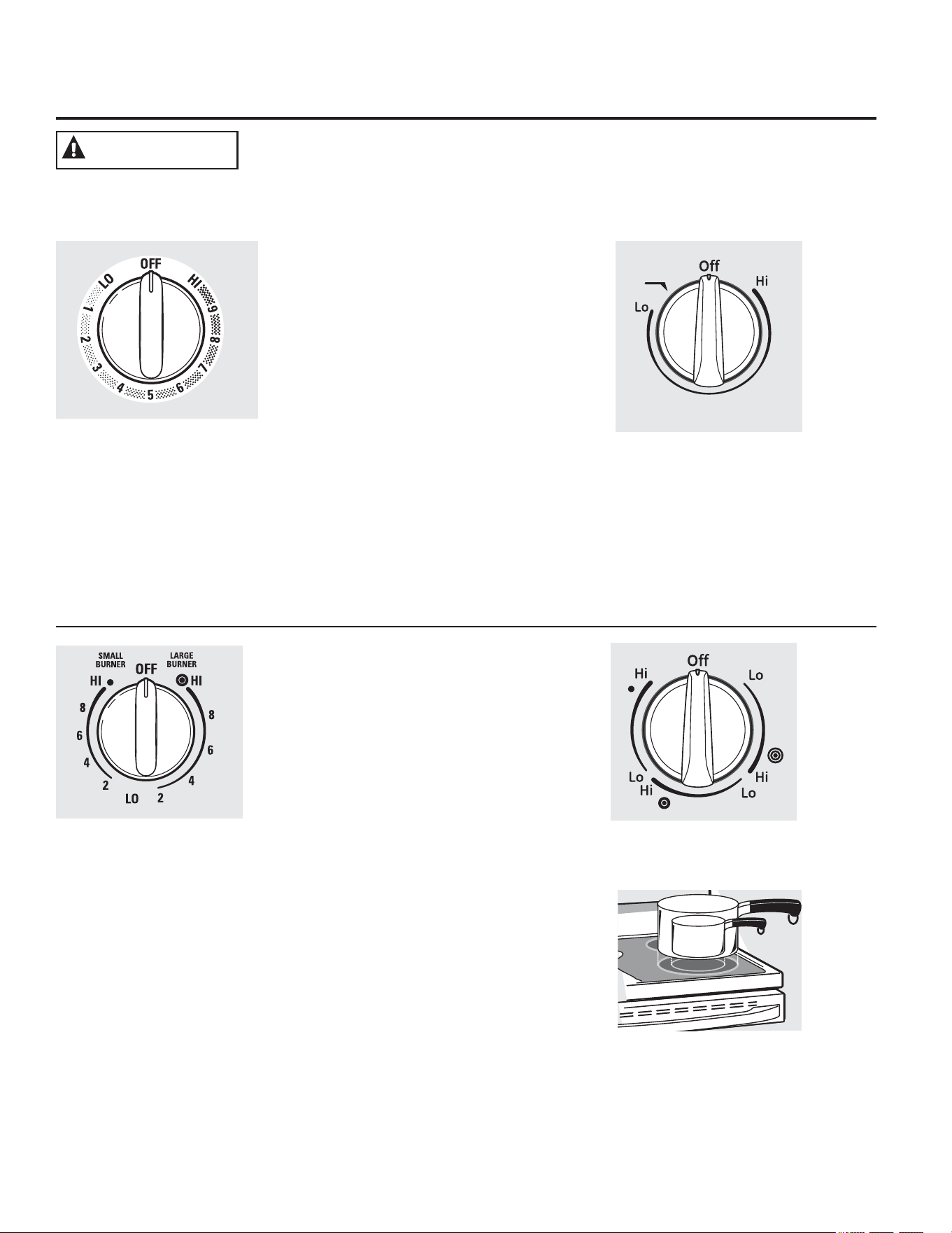
+RZWR6HW
'XDODQG7ULSOH6XUIDFH8QLWV
DQG&RQWURO.QREV
RQVRPHPRGHOV
7KHVXUIDFHXQLWKDVRUFRRNLQJVL]HV
WRVHOHFWIURPVR\RXFDQPDWFKWKHVL]H
RIWKHXQLWWRWKHVL]HRIWKHFRRNZDUH\RXDUH
XVLQJ
$WERWK2)) DQG+, WKH
FRQWUROFOLFNV LQWRSRVLWLRQ
<RXPD\KHDUVOLJKWFOLFNLQJ
VRXQGVGXULQJFRRNLQJ
LQGLFDWLQJWKHFRQWUROLV
PDLQWDLQLQJ\RXUGHVLUHG
VHWWLQJ
%HVXUH\RXWXUQWKHFRQWURO
NQREWR2))ZKHQ\RXILQLVK
FRRNLQJ
0RGHOVZLWKD'XDO5LQJVXUIDFH
HOHPHQWRQO\
:$51,1*
3XVKWKHNQRELQDQGWXUQLQHLWKHUGLUHFWLRQWR
WKHVHWWLQJ\RXZDQW
$VXUIDFH21LQGLFDWRUOLJKWZLOOJORZZKHQDQ\
VXUIDFHXQLWLVRQ
)RUJODVVFRRNWRSVXUIDFHV
$+27&22.723 LQGLFDWRUOLJKWZLOO
■FRPHRQZKHQWKHXQLWLVKRWWRWKHWRXFK
■VWD\RQHYHQDIWHUWKHXQLWLVWXUQHGRII
■VWD\RQXQWLOWKHXQLWLVFRROHGWR
DSSUR[LPDWHO\)
Melt
Rear
8
7
6
54
3
2
9
1
0HOWVHWWLQJRQVRPHPRGHOVZLOOPHOW
FKRFRODWHRUEXWWHU6LPPHUVHWWLQJRQVRPH
PRGHOVZLOOVLPPHUVDXFHV
0RGHOVZLWKD7UL5LQJVXUIDFH
HOHPHQWRQO\
8VLQJWKH:DUPLQJ=RQH
)22'32,621+$=$5'%DFWHULDPD\JURZLQ
IRRGDWWHPSHUDWXUHVEHORZ)
■$OZD\VVWDUWZLWKKRWIRRG'RQRWXVHZDUP
VHWWLQJWRKHDWFROGIRRG
■'RQRWXVHZDUPVHWWLQJIRUPRUHWKDQ
KRXUV
)DLOXUHWRIROORZWKHVHLQVWUXFWLRQVPD\UHVXOWLQ
IRRGERUQHLOOQHVV
7KH:$50,1*=21(ORFDWHGLQWKHEDFN
FHQWHURIWKHJODVVVXUIDFHZLOONHHSKRWFRRNHG
IRRGDWVHUYLQJWHPSHUDWXUH$OZD\VVWDUWZLWK
KRWIRRG'RQRWXVHWRKHDWFROGIRRG3ODFLQJ
XQFRRNHGRUFROGIRRGRQWKH:$50,1*=21(
FRXOGUHVXOWLQIRRGERUQHLOOQHVV
7RXVHWKH:$50,1*=21(
7RXFKWKH:$50,1*=21(212))SDG
7RXFKWKHORZPHGLXPRUKLJK
SDGWRVHOHFWWKHGHVLUHGFRQWUROVHWWLQJ
7RXFKWKH67$57SDG:$50(5+2721
ZLOOEHLQWKHFRQWUROGLVSOD\
7RWXUQRIIWKH:$50,1*=21(
7RXFKWKH:$50,1*=21(212))SDG
127(7KH&/($52))SDGZLOOQRWWXUQRII
WKH:$50,1*=21(
)RUEHVWUHVXOWVDOOIRRGVRQWKH:$50,1*
=21(VKRXOGEHFRYHUHGZLWKDOLGRUDOXPLQXP
IRLO:KHQZDUPLQJSDVWULHVRUEUHDGVWKH
FRYHUVKRXOGEHYHQWHGWRDOORZPRLVWXUHWR
HVFDSH
8VHWKHORZHVWVHWWLQJIRUEUHDGVDQGSDVWULHV
8VHDPHGLXPVHWWLQJIRUYHJHWDEOHVVDXFHV
VWHZVFUHDPVRXSVEXWWHUDQGFKRFRODWH8VH
WKHKLJKHVWVHWWLQJIRUVRXSVOLTXLGDQGKRW
EHYHUDJHV7KHVHLQLWLDOVXJJHVWHGVHWWLQJVDUH
IRUUHIHUHQFHRQO\7KHWHPSHUDWXUHW\SHDQG
DPRXQWRIIRRGW\SHRISDQDQGWKHWLPHKHOG
ZLOODIIHFWWKHTXDOLW\RIWKHIRRG
$OZD\VXVHSRWKROGHUVRURYHQPLWWVZKHQ
UHPRYLQJIRRGIURPWKH:$50,1*=21(
VLQFHFRRNZDUHDQGSODWHVZLOOEHKRW
127(7KHVXUIDFHZDUPHUZLOOQRWJORZUHG
OLNHWKHFRRNLQJHOHPHQWV
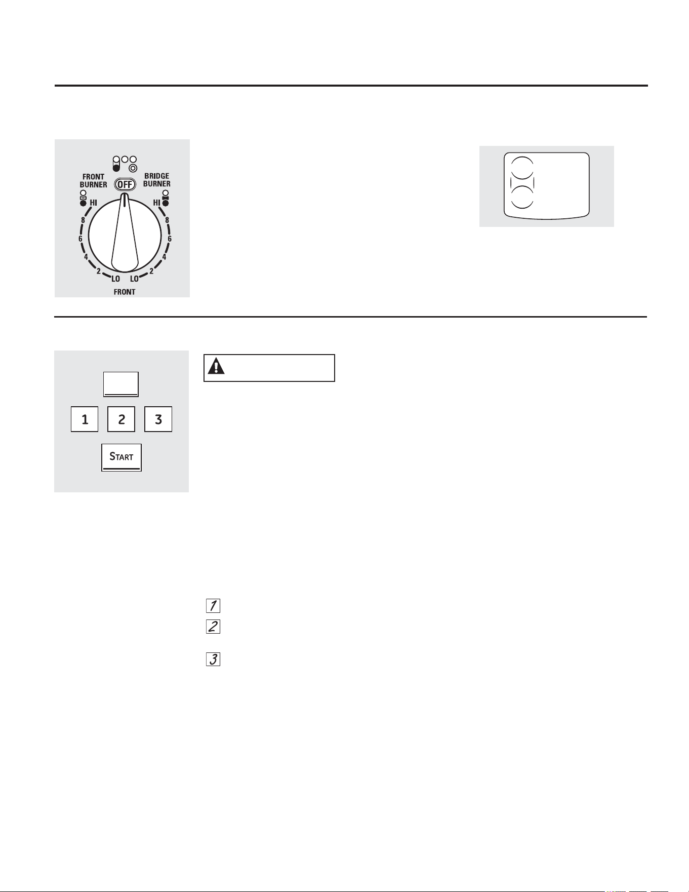
0RGHOVZLWKDEULGJHEXUQHURQO\
:DUPLQJ=RQH
*($SSOLDQFHVFRP
7KURXJKRXWWKLVPDQXDOIHDWXUHVDQGDSSHDUDQFHPD\YDU\IURP\RXUPRGHO
8VLQJWKH%ULGJH%XUQHURQVRPHPRGHOV
7RXVHWKHEULGJHEXUQHUWXUQWKHOHIWIURQW
FRQWURONQREWRWKH%5,'*(%851(5VHWWLQJV
)RUIXOOEULGJHVXUIDFHXQLWRSHUDWLRQDOVRWXUQ
RQWKHOHIWUHDUVXUIDFHXQLW
7RXVHRQO\WKHIURQWVXUIDFHXQLWWXUQ
WKHFRQWURONQREWRWKH)5217%851(5VHWWLQJV
:$51,1*
WARMING
ZONE
ON/OFF
7HPSHUDWXUH/LPLWHURQ5DGLDQW*ODVV&RRNWRSV
(YHU\UDGLDQWVXUIDFHXQLWKDVDWHPSHUDWXUH
OLPLWHU
7KHWHPSHUDWXUHOLPLWHUSURWHFWVWKHJODVV
FRRNWRSIURPJHWWLQJWRRKRW
7KHWHPSHUDWXUHOLPLWHUPD\F\FOHWKHVXUIDFH
XQLWVRIIIRUDWLPHLI
■WKHSDQERLOVGU\
■WKHSDQERWWRPLVQRWIODW
■WKHSDQLVRIIFHQWHU
■WKHUHLVQRSDQRQWKHXQLW
8VLQJWKHVXUIDFHXQLWV
+RPH&DQQLQJ7LSV
%HVXUHWKHFDQQHULVFHQWHUHGRYHUWKHVXUIDFH
XQLW
0DNHVXUHWKHFDQQHULVIODWRQWKHERWWRP
7RSUHYHQWEXUQVIURPVWHDPRUKHDWXVH
FDXWLRQZKHQFDQQLQJ
8VHUHFLSHVDQGSURFHGXUHVIURPUHSXWDEOH
VRXUFHV7KHVHDUHDYDLODEOHIURP
PDQXIDFWXUHUVVXFKDV%DOO
DQG.HUU
DQGWKH
'HSDUWPHQWRI$JULFXOWXUH([WHQVLRQ6HUYLFH
)ODWERWWRPHGFDQQHUVDUHUHFRPPHQGHG8VH
RIZDWHUEDWKFDQQHUVZLWKULSSOHGERWWRPV
PD\H[WHQGWKHWLPHUHTXLUHGWREULQJWKH
ZDWHUWRDERLO
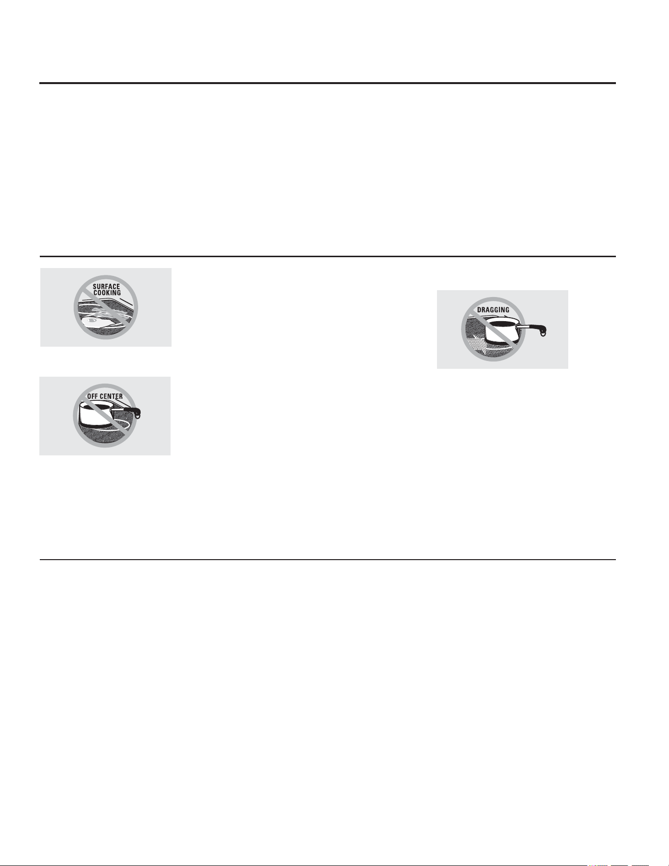
1HYHUFRRNGLUHFWO\RQWKHJODVV
$OZD\VXVHFRRNZDUH
)RU0RGHOV:LWKD5DGLDQW*ODVV&RRNWRS
7KHUDGLDQWFRRNWRSIHDWXUHVKHDWLQJXQLWV
EHQHDWKDVPRRWKJODVVVXUIDFH
127($VOLJKWRGRULVQRUPDOZKHQDQHZ
FRRNWRSLVXVHGIRUWKHILUVWWLPH,WLVFDXVHG
E\WKHKHDWLQJRIQHZSDUWVDQGLQVXODWLQJ
PDWHULDOVDQGZLOOGLVDSSHDULQDVKRUWWLPH
127(2QPRGHOVZLWKOLJKWFRORUHGJODVV
FRRNWRSVLWLVQRUPDOIRUWKHFRRNLQJ]RQHVWR
FKDQJHFRORUZKHQKRWRUFRROLQJGRZQ7KLVLV
WHPSRUDU\DQGZLOOGLVDSSHDUDVWKHJODVVFRROV
WRURRPWHPSHUDWXUH
7KHVXUIDFHXQLWZLOOF\FOHRQDQGRIIWR
PDLQWDLQ\RXUVHOHFWHGFRQWUROVHWWLQJ
,WLVVDIHWRSODFHKRWFRRNZDUHRQWKHJODVV
VXUIDFHHYHQZKHQWKHFRRNWRSLVFRRO
(YHQDIWHUWKHVXUIDFHXQLWVDUHWXUQHGRIIWKH
JODVVFRRNWRSUHWDLQVHQRXJKKHDWWRFRQWLQXH
FRRNLQJ7RDYRLGRYHUFRRNLQJUHPRYHSDQV
IURPWKHVXUIDFHXQLWVZKHQWKHIRRGLVFRRNHG
$YRLGSODFLQJDQ\WKLQJRQWKHVXUIDFHXQLWXQWLO
LWKDVFRROHGFRPSOHWHO\
'RQRWVOLGHFRRNZDUHDFURVVWKHFRRNWRSEHFDXVH
LWFDQVFUDWFKWKHJODVV³WKHJODVVLVVFUDWFKUHVLVWDQW
QRWVFUDWFKSURRI
■:DWHUVWDLQVPLQHUDOGHSRVLWVDUH
UHPRYDEOHXVLQJWKHFOHDQLQJFUHDPRUIXOO
VWUHQJWKZKLWHYLQHJDU
■8VHRIZLQGRZFOHDQHUPD\OHDYHDQ
LULGHVFHQWILOPRQWKHFRRNWRS7KHFOHDQLQJ
FUHDPZLOOUHPRYHWKLVILOP
■'RQ·WVWRUHKHDY\LWHPVDERYHWKHFRRNWRS,I
WKH\GURSRQWRWKHFRRNWRSWKH\FDQFDXVH
GDPDJH
■'RQRWXVHWKHVXUIDFHDVDFXWWLQJERDUG
$OZD\VSODFHWKHSDQLQWKHFHQWHURI
WKHVXUIDFHXQLW\RXDUHFRRNLQJRQ
6HOHFWLQJW\SHVRIFRRNZDUHIRU
UDGLDQWJODVVFRRNWRSPRGHOV *($SSOLDQFHVFRP
6WDLQOHVV6WHHO
UHFRPPHQGHG
$OXPLQXP
KHDY\ZHLJKWUHFRPPHQGHG
*RRGFRQGXFWLYLW\$OXPLQXPUHVLGXHV
VRPHWLPHVDSSHDUDVVFUDWFKHVRQWKHFRRNWRS
EXWFDQEHUHPRYHGLIFOHDQHGLPPHGLDWHO\
%HFDXVHRILWVORZPHOWLQJSRLQWWKLQZHLJKW
DOXPLQXPVKRXOGQRWEHXVHG
&RSSHU%RWWRP
UHFRPPHQGHG
&RSSHUPD\OHDYHUHVLGXHVZKLFKFDQDSSHDU
DVVFUDWFKHV7KHUHVLGXHVFDQEHUHPRYHGDV
ORQJDVWKHFRRNWRSLVFOHDQHGLPPHGLDWHO\
+RZHYHUGRQRWOHWWKHVHSRWVERLOGU\
2YHUKHDWHGPHWDOFDQERQGWRJODVVFRRNWRSV
$QRYHUKHDWHGFRSSHUERWWRPSRWZLOOOHDYHD
UHVLGXHWKDWZLOOSHUPDQHQWO\VWDLQWKHFRRNWRS
LIQRWUHPRYHGLPPHGLDWHO\
3RUFHODLQ(QDPHORQ&DVW,URQ
UHFRPPHQGHGLIERWWRPRISDQLVFRDWHG
3RUFHODLQ(QDPHORQ6WHHO
QRWUHFRPPHQGHG
+HDWLQJHPSW\SDQVFDQFDXVHSHUPDQHQW
GDPDJHWRFRRNWRSJODVV7KHHQDPHOFDQPHOW
DQGERQGWRWKHFHUDPLFFRRNWRS
*ODVVFHUDPLF
QRWUHFRPPHQGHG
3RRUSHUIRUPDQFH:LOOVFUDWFKWKHVXUIDFH
6WRQHZDUH
QRWUHFRPPHQGHG
3RRUSHUIRUPDQFH0D\VFUDWFKWKHVXUIDFH
&DVW,URQ
QRWUHFRPPHQGHG³XQOHVVGHVLJQHGVSHFLILFDOO\
IRUJODVVFRRNWRSV
3RRUFRQGXFWLYLW\DQGVORZWRDEVRUEKHDW:LOO
VFUDWFKWKHFRRNWRSVXUIDFH
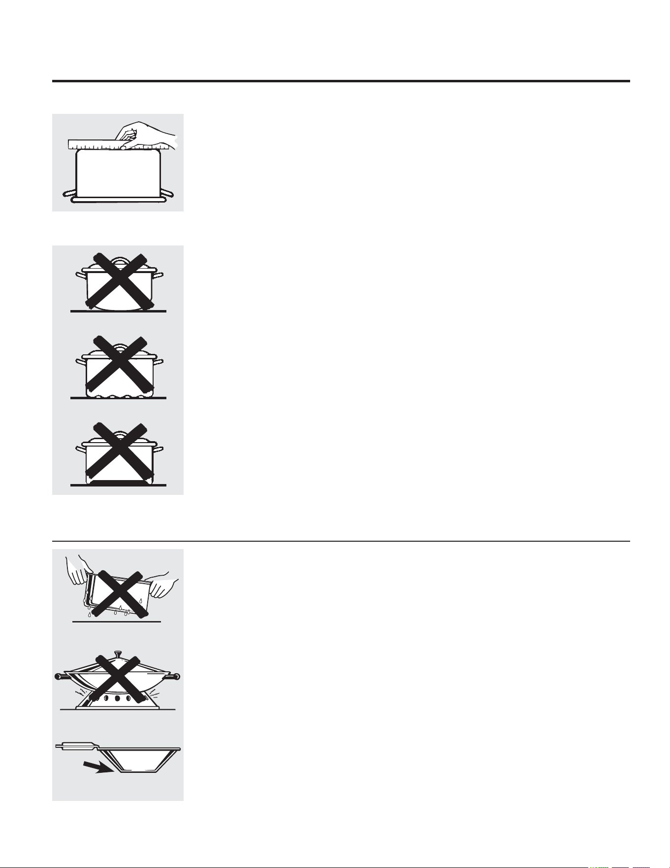
&KHFNSDQVIRUIODWERWWRPVE\
XVLQJDVWUDLJKWHGJH
3DQVZLWKURXQGHGFXUYHG
ULGJHGRUZDUSHGERWWRPVDUHQRW
UHFRPPHQGHG
7KHIROORZLQJLQIRUPDWLRQZLOOKHOS\RXFKRRVHFRRNZDUHZKLFKZLOOJLYHJRRGSHUIRUPDQFHRQJODVVFRRNWRSV
)RU%HVW5HVXOWV
■
3ODFHRQO\GU\SDQVRQWKHVXUIDFH
HOHPHQWV'RQRWSODFHOLGVRQWKHVXUIDFH
HOHPHQWVSDUWLFXODUO\ZHWOLGV:HWSDQV
DQGOLGVPD\VWLFNWRWKHVXUIDFHZKHQFRRO
■'RQRWXVHZRNVWKDWKDYHVXSSRUWULQJV
7KLVW\SHRIZRNZLOOQRWKHDWRQJODVV
VXUIDFHHOHPHQWV
■:HUHFRPPHQGWKDW\RXXVHRQO\DIODW
ERWWRPHGZRN7KH\DUHDYDLODEOHDW\RXU
ORFDOUHWDLOVWRUH7KHERWWRPRIWKHZRN
VKRXOGKDYHWKHVDPHGLDPHWHUDVWKH
VXUIDFHHOHPHQWWRHQVXUHSURSHUFRQWDFW
■6RPHVSHFLDOFRRNLQJSURFHGXUHVUHTXLUH
VSHFLILFFRRNZDUHVXFKDVSUHVVXUH
FRRNHUVRUGHHSIDWIU\HUV$OOFRRNZDUH
PXVWKDYHIODWERWWRPVDQGEHWKHFRUUHFW
VL]H
'RQRWSODFHZHWSDQV
RQWKHJODVVFRRNWRS
'RQRWXVHZRNVZLWKVXSSRUW
ULQJVRQWKHJODVVFRRNWRS
8VHIODWERWWRPHGZRNV
RQWKHJODVVFRRNWRS
127()ROORZDOOFRRNZDUHPDQXIDFWXUHU·VUHFRPPHQGDWLRQVZKHQXVLQJDQ\W\SHRIFRRNZDUHRQ
WKHFHUDPLFFRRNWRS
7KURXJKRXWWKLVPDQXDOIHDWXUHVDQGDSSHDUDQFHPD\YDU\IURP\RXUPRGHO
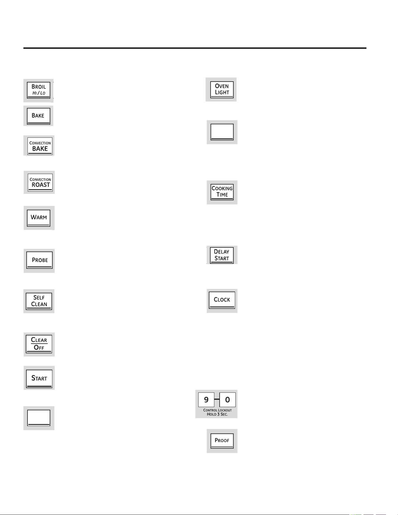
8VLQJWKHRYHQFRQWUROV
%52,/+,/23DG
7RXFKWKLVSDGWRVHOHFWWKHEURLOIXQFWLRQ6HHWKH
+RZWR6HWWKH2YHQIRU%URLOLQJVHFWLRQ
%$.(3DG
7RXFKWKLVSDGWRVHOHFWWKHEDNHIXQFWLRQ6HH
WKH+RZWR6HWWKH2YHQIRU%DNLQJVHFWLRQ
&219(&7,21%$.(3DG
8VHVDIDQWRFLUFXODWHDLULQWKHRYHQ6HHWKH
8VLQJWKHFRQYHFWLRQRYHQVHFWLRQ
&219(&7,2152$673DG
7RXFKWRURDVWODUJHWHQGHUFXWVRIPHDW
6HHWKH8VLQJWKHFRQYHFWLRQRYHQVHFWLRQ
:$503DG
7RXFKWRNHHSFRRNHGIRRGVZDUP
6HHWKH+RZWR6HWWKH2YHQIRU:DUPLQJVHFWLRQ
352%(3DG
7RXFKZKHQXVLQJWKHSUREHWRDXWRPDWLFDOO\
FRRNWRDGHVLUHGLQWHUQDOIRRGWHPSHUDWXUH
6HHWKH8VLQJWKH3UREHVHFWLRQ
6(/)&/($13DG
7RXFKWRVHOIFOHDQWKHRYHQ
6HHWKH8VLQJWKH6HOI&OHDQLQJ2YHQVHFWLRQ
&/($52))3DG
7RXFKWRFDQFHO$//RYHQRSHUDWLRQVH[FHSWWKH
FORFNDQGWLPHU
67$573DG
0XVWEHWRXFKHGWRVWDUWDQ\FRRNLQJRUFOHDQLQJ
IXQFWLRQ
:$50,1*=21(3DG
7RXFKWRNHHSKRWFRRNHGIRRGZDUP6HHWKH
8VLQJWKH:DUPLQJ=RQHVHFWLRQ
29(1/,*+73DG
7RXFKWRWXUQWKHRYHQOLJKWVRQRURII
.,7&+(17,0(5212))3DG
127(:KHQVHWWLQJWLPHV\RXDUHVHWWLQJKRXUV
DQGPLQXWHVRQO\7KHORZHVWWLPH\RXFDQVHWLV
RQHPLQXWH
7RXFKWRVHWWKHNLWFKHQWLPHU
6HHWKH8VLQJWKH.LWFKHQ7LPHUVHFWLRQ
&22.,1*7,0(3DG
127(:KHQVHWWLQJWLPHV\RXDUHVHWWLQJKRXUV
DQGPLQXWHVRQO\7KHORZHVWWLPH\RXFDQVHWLV
RQHPLQXWH
7RXFKWKLVSDGDQGWKHQWRXFKWKHQXPEHUSDGV
WRVHWWKHDPRXQWRIWLPH\RXZDQW\RXUIRRG
WRFRRN7KHRYHQZLOOVKXWRIIZKHQWKHFRRNLQJ
WLPHKDVUXQRXW
'(/$<67$573DG
7RXFKWKLVSDGWRVHWWKHRYHQWRVWDUW
DXWRPDWLFDOO\DWDWLPH\RXVHW
&/2&.3DG
7KHFORFNPXVWEHVHWWRWKHFRUUHFWWLPHRIGD\
IRUWKHDXWRPDWLFRYHQWLPLQJIXQFWLRQVWRZRUN
SURSHUO\7KHWLPHRIGD\FDQQRWEHFKDQJHG
GXULQJDWLPHGEDNLQJRUVHOIFOHDQLQJF\FOH
6HH7RVHWWKHFORFNVHFWLRQ
,I\RXURYHQZDVVHWIRUDWLPHGRYHQRSHUDWLRQ
DQGDSRZHURXWDJHRFFXUUHGWKHFORFNDQGDOO
SURJUDPPHGIXQFWLRQVPXVWEHUHVHW7KHWLPH
RIGD\ZLOOIODVKLQWKHGLVSOD\ZKHQWKHUHKDV
EHHQDSRZHURXWDJH
&21752//2&.287
7KHFRQWUROSDGVFDQEHORFNHGVRWKH\FDQQRW
EHDFWLYDWHGZKHQWRXFKHG6HHWKH+RZWR
/RFN2XWWKH&RQWUROVVHFWLRQ
3522)3DG
7RXFKWRUDLVH\HDVWOHDYHQHGSURGXFWV6HHWKH
+RZWR6HWWKH2YHQIRU3URRILQJVHFWLRQ
KITCHEN
TIMER
ON/OFF
WARMING
ZONE
ON/OFF
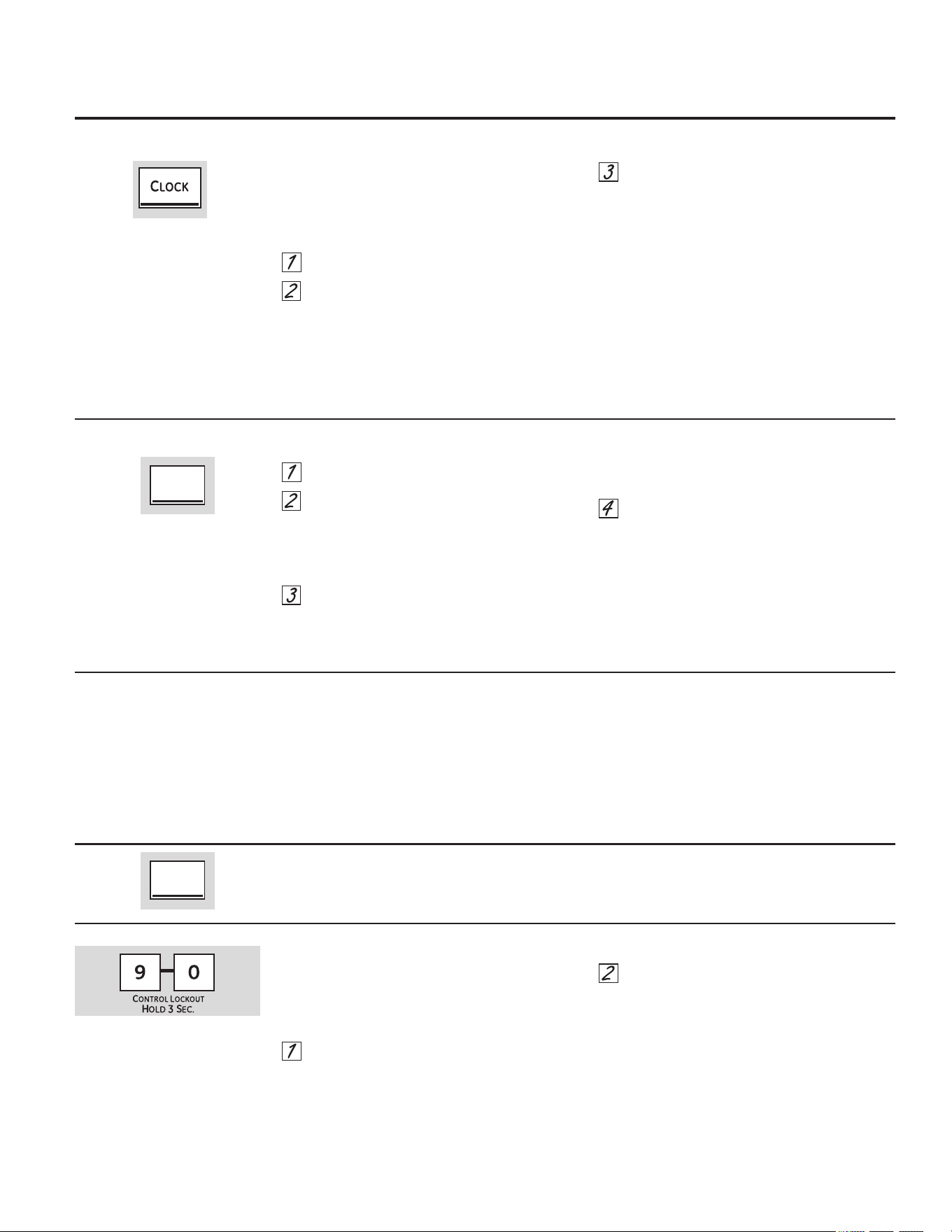
7R6HWWKH.LWFKHQ7LPHU
7RXFKWKH.,7&+(17,0(5212))SDG
7RXFKWKHQXPEHUSDGVXQWLOWKHDPRXQW
RIWLPH\RXZDQWVKRZVLQWKHGLVSOD\)RU
H[DPSOHWRVHWKRXUVDQGPLQXWHV
WRXFK DQG LQWKDWRUGHU,I\RXPDNH
DPLVWDNHWRXFKWKH.,7&+(17,0(521
2))SDGDQGEHJLQDJDLQ
7RXFKWKH67$57SDG
$IWHUWRXFKLQJWKH67$57SDG6(7GLVDSSHDUV
WKLVWHOOV\RXWKHWLPHLVFRXQWLQJGRZQDOWKRXJK
WKHGLVSOD\GRHVQRWFKDQJHXQWLORQHPLQXWH
KDVSDVVHG6HFRQGVZLOOQRWEHVKRZQLQWKH
GLVSOD\XQWLOWKHODVWPLQXWHLVFRXQWLQJGRZQ
:KHQWKHNLWFKHQWLPHUUHDFKHVWKH
FRQWUROZLOOEHHSWLPHVIROORZHGE\RQH
EHHSHYHU\VHFRQGVXQWLOWKH.,7&+(1
7,0(5212)) SDGLVWRXFKHG
7KHVHFRQGWRQHFDQEHFDQFHOOHGE\
IROORZLQJWKHVWHSVLQWKH6SHFLDOIHDWXUHVRI
\RXURYHQFRQWUROVHFWLRQXQGHU7RQHVDWWKH
(QGRID7LPHG&\FOH
7KH.LWFKHQ7LPHULVLQKRXUVDQG
PLQXWHV
7KH.LWFKHQ7LPHUGRHVQRWFRQWURORYHQ
RSHUDWLRQV7KHPD[LPXPVHWWLQJRQWKH
.LWFKHQ7LPHULVKRXUVDQGPLQXWHV
7R5HVHWWKH.LWFKHQ7LPHU
+RZWR/RFN2XWWKH&RQWUROV
7R6HWWKH&ORFN
,IWKHGLVSOD\LVVWLOOVKRZLQJWKHWLPHUHPDLQLQJ
\RXPD\FKDQJHLWE\WRXFKLQJWKH.,7&+(1
7,0(5212)) SDGWKHQWRXFKLQJWKHQXPEHU
SDGVVRWKDWWKHWLPH\RXZDQWDSSHDUVLQWKH
GLVSOD\
,IWKHUHPDLQLQJWLPHLVQRWLQWKHGLVSOD\FORFN
GHOD\VWDUWRUFRRNLQJWLPHDUHLQWKHGLVSOD\
UHFDOOWKHUHPDLQLQJWLPHE\WRXFKLQJWKH
.,7&+(17,0(5212)) SDGDQGWKHQWRXFK
WKHQXPEHUSDGVWRHQWHUWKHQHZWLPH\RX
ZDQW
&RQWURO/RFNRXWZLOODOORZ\RXWRORFNRXWWKH
WRXFKSDGVVRWKH\FDQQRWEHDFWLYDWHGZKHQ
WRXFKHG
7RORFNXQORFNWKHFRQWUROV
7RXFKDQGKROGWKHDQGSDGVDWWKH
VDPHWLPHIRUVHFRQGV7KHGLVSOD\ZLOO
VKRZ/2&21
7RXQORFNWKHFRQWUROWRXFKDQGKROGWKH
DQGSDGVDWWKHVDPHWLPHIRU
VHFRQGV7KHGLVSOD\ZLOOVKRZ/2&2))
:KHQWKLVIHDWXUHLVRQWKHWRXFKSDGVZLOOQRW
UHVSRQGH[FHSWIRUWKH&OHDU2IISDG
■7KHDGMXVWPHQWZLOOEHUHWDLQHGLQPHPRU\
DIWHUDSRZHUIDLOXUH
7KHFORFNPXVWEHVHWWRWKHFRUUHFWWLPHRIGD\
IRUWKH'HOD\6WDUWIXQFWLRQVWRZRUNSURSHUO\
7KHWLPHRIGD\FDQQRWEHFKDQJHGGXULQJ
DGHOD\HGFRRNLQJRUDGHOD\HGVHOIFOHDQLQJ
F\FOH
7RXFKWKH&/2&.SDG
7RXFKWKHQXPEHUSDGVXQWLOWKHFRUUHFW
WLPHRIGD\LVVKRZQLQWKHGLVSOD\,IWKH
QXPEHUSDGVDUHQRWWRXFKHGZLWKLQRQH
PLQXWHDIWHU\RXWRXFKWKH&/2&.SDG
WKHGLVSOD\UHYHUWVWRWKHRULJLQDOVHWWLQJ,I
WKLVKDSSHQVWRXFKWKH&/2&.SDGDQG
HQWHUWKHWLPHRIGD\
7RXFKWKH67$57SDGXQWLOWKHWLPHRIGD\
VKRZVLQWKHGLVSOD\7KLVHQWHUVWKHWLPH
DQGVWDUWVWKHFORFN
7RFKHFNWKHWLPHRIGD\ZKHQWKHGLVSOD\LV
VKRZLQJRWKHULQIRUPDWLRQWRXFKWKH&/2&.
SDG7KHWLPHRIGD\VKRZVXQWLODQRWKHUSDG
LVWRXFKHG7RFKDQJHWKHWLPHIRUPDWRUWXUQ
RIIWKHFORFNGLVSOD\VHHWKH6SHFLDO)HDWXUHV
VHFWLRQ
7R&DQFHOWKH.LWFKHQ7LPHU
7RXFKWKH.,7&+(17,0(5212))SDGWZLFH
8VLQJWKHFORFNNLWFKHQWLPHUDQGFRQWUROORFNRXW *($SSOLDQFHVFRP
KITCHEN
TIMER
ON/OFF
KITCHEN
TIMER
ON/OFF
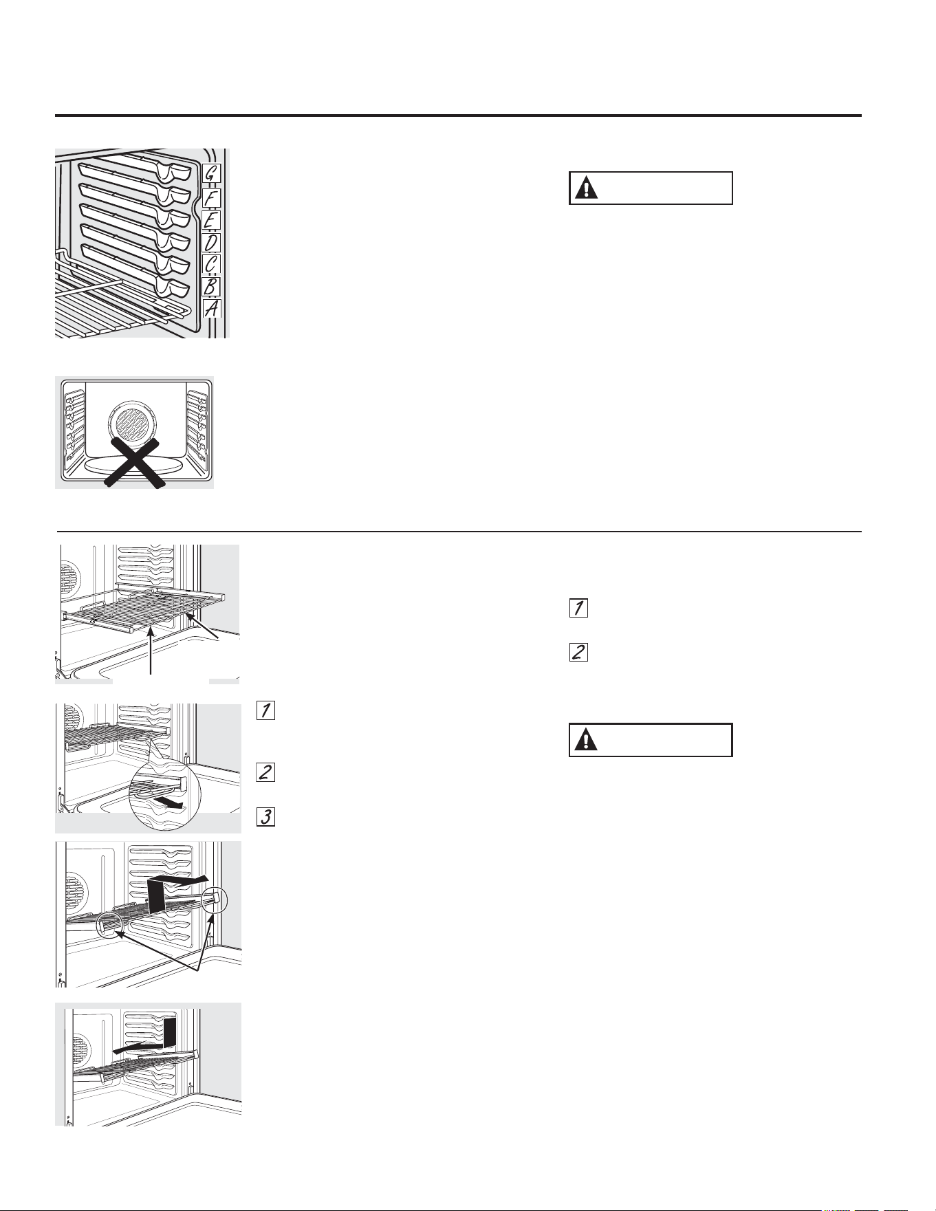
7RDYRLGSRVVLEOHEXUQVSODFHWKHUDFNVLQWKHGHVLUHGSRVLWLRQEHIRUH\RXWXUQRQWKHRYHQ
%HIRUH\RXEHJLQ«
7KHUDFNVKDYHVWRSVVRWKDWZKHQSODFHG
FRUUHFWO\RQWKHVXSSRUWVWKH\ZLOOVWRSEHIRUH
FRPLQJFRPSOHWHO\RXWDQGZLOOQRWWLOW
:KHQSODFLQJDQGUHPRYLQJFRRNZDUHSXOOWKH
UDFNRXWXQWLOLWVWRSV
2QVRPHPRGHOVWKHEDNHKHDWLQJHOHPHQW
LVXQGHUWKHRYHQIORRU1HYHUSODFHFRRNLQJ
XWHQVLOVEDNLQJVWRQHVIRLORUDQ\RWKHULWHPV
RQWKHRYHQIORRU
7RUHPRYHDUDFN SXOOLWWRZDUG\RXWLOWWKH
IURQWHQGXSDQGSXOOLWRXW
7RUHSODFH SODFHWKHHQGRIWKHUDFNVWRS
ORFNVRQWKHVXSSRUWWLOWXSWKHIURQWDQGSXVK
WKHUDFNLQ
%851+$=$5'$YRLGWRXFKLQJWKHKRWGRRU
VXUIDFHZKHQXVLQJWKHRYHQUDFNLQWKHORZHVW
SRVLWLRQ$OZD\VXVHKDQGVDQGPLWWHQSRW
KROGHUVWRPRYHWKHUDFN3XOOWKHUDFNRXWD
IHZLQFKHVDQGWKHQFDUHIXOO\JUDVSWKHVLGHVRI
WKHUDFNWRSXOOLWRXWWKHUHVWRIWKHZD\
7KHQXPEHURIUDFNSRVLWLRQVPD\
YDU\E\PRGHO
([WHQVLRQ5DFNRQVRPHPRGHOV
:KHQSODFLQJDQGUHPRYLQJFRRNZDUH
DOZD\VSXOOWKHUDFNRXWE\LWVXSSHUIURQW
UDLOWRLWVIXOO\RSHQSRVLWLRQ
'RQRWH[WHQGWKHUDFNTXLFNO\)RRGPD\
VOLGHRIIWKHIURQWRIWKHUDFN
7RUHPRYHWKHUDFN
0DNHVXUHWKHUDFNLVSXVKHGDOOWKHZD\
LQWRWKHRYHQVRWKDWVLGHSDGGOHVRQWKH
UDFNIURPGLVHQJDJHGZLWKRYHQVXSSRUW
6OLGHWKHUDFNWRZDUG\RXWRWKHEXPS
VWRSSRVLWLRQRQWKHUDFNVXSSRUW
)LUPO\JUDVSERWKVLGHVRIWKHUDFNIUDPH
DQGWKHVOLGLQJUDFNWLOWWKHIURQWHQGXS
DQGSXOOLWRXW
127(:KHQKDQGOLQJWKHH[WHQVLRQUDFNGR
QRWDOORZWKHVOLGLQJSRUWLRQWRIDOORSHQ7KLV
FDQGDPDJHWKHVOLGHV
7RUHSODFHWKHUDFN
)LUPO\JUDVSERWKVLGHVRIWKHUDFN
IUDPHDQGWKHVOLGLQJUDFN
3ODFHWKHFXUYHGHQGRIWKHUDFNVWRS
ORFNVRQWRWKHRYHQVXSSRUWVWLOWXSWKH
IURQWRIWKHUDFNDQGSXVKLWLQDVIDUDVLW
ZLOOJR
1HYHUXVHWKHUDFNZKHQLWVIUDPHLVQRWIXOO\
LQVHUWHGLQWKHRYHQDQGORFNHGLQWRSRVLWLRQ
:KHQWKHUDFNLVSURSHUO\LQVWDOOHGDQG
ORFNHGLQWRSRVLWLRQWKHORFNLQJVLGHSDGGOHV
RQWKHUDFNIUDPHZLOOFOLFNORFNLQWRSODFH
RQWKHRYHQVXSSRUWV,IWKHVLGHSDGGOHV
GLGQRWFOLFNORFNLQWRSRVLWLRQUHSHDWWKH
VWHSVDERYHDQGPDNHVXUHWKHVLGHSDGGOHV
KDYHEHHQFRUUHFWO\FOHDQHGDQGOXEULFDWHG
6HH([WHQVLRQ5DFNLQWKH&DUHDQGFOHDQLQJ
VHFWLRQ
8SSHU)URQW
5DLO
)XOO\2SHQ3RVLWLRQ
&$87,21
&$87,21
*UDVSKHUH
1HYHUSODFHFRRNLQJXWHQVLOVEDNLQJVWRQHV
IRLORUDQ\RWKHULWHPVRQWKHRYHQIORRU
8VLQJWKHRYHQ
*($SSOLDQFHVFRP
+RZWR6HWWKH2YHQIRU%DNLQJRU5RDVWLQJ
7RXFKWKH%$.(SDG
7RXFKWKHQXPEHUSDGVXQWLOWKHGHVLUHG
WHPSHUDWXUHLVGLVSOD\HG
7RXFKWKH67$57SDG
7KHRYHQZLOOVWDUWDXWRPDWLFDOO\7KHGLVSOD\ZLOO
VKRZWKHFKDQJLQJWHPSHUDWXUHVWDUWLQJDWÛ)
7KHWHPSHUDWXUHGLVSOD\ZLOOVWDUWWRFKDQJHRQFH
WKHRYHQWHPSHUDWXUHUHDFKHVÛ):KHQWKH
RYHQUHDFKHVWKHVHOHFWHGWHPSHUDWXUHWKHRYHQ
FRQWUROZLOOEHHSVHYHUDOWLPHVDQGWKHGLVSOD\ZLOO
VKRZWKHRYHQWHPSHUDWXUH
127( <RXPD\KHDUWKHFRQYHFWLRQIDQRQ
VRPHPRGHOVZKLOHWKHRYHQLVSUHKHDWLQJ7KH
IDQZLOOVWRSDIWHUWKHRYHQLVSUHKHDWHGDQG
WKHGLVSOD\VKRZV\RXUVHWWHPSHUDWXUH7KLVLV
QRUPDO
7RFKDQJHWKHRYHQWHPSHUDWXUHGXULQJWKH%$.(
F\FOHWRXFKWKH%$.(SDGDQGWKHQWKHQXPEHU
SDGVWRJHWWKHQHZWHPSHUDWXUH
&KHFNIRRGIRUGRQHQHVVDWWKHPLQLPXPWLPH
RQWKHUHFLSH&RRNORQJHULIQHFHVVDU\
7RXFKWKH&/($52))SDGZKHQEDNLQJLV
ILQLVKHGDQGWKHQUHPRYHWKHIRRGIURPWKH
RYHQ
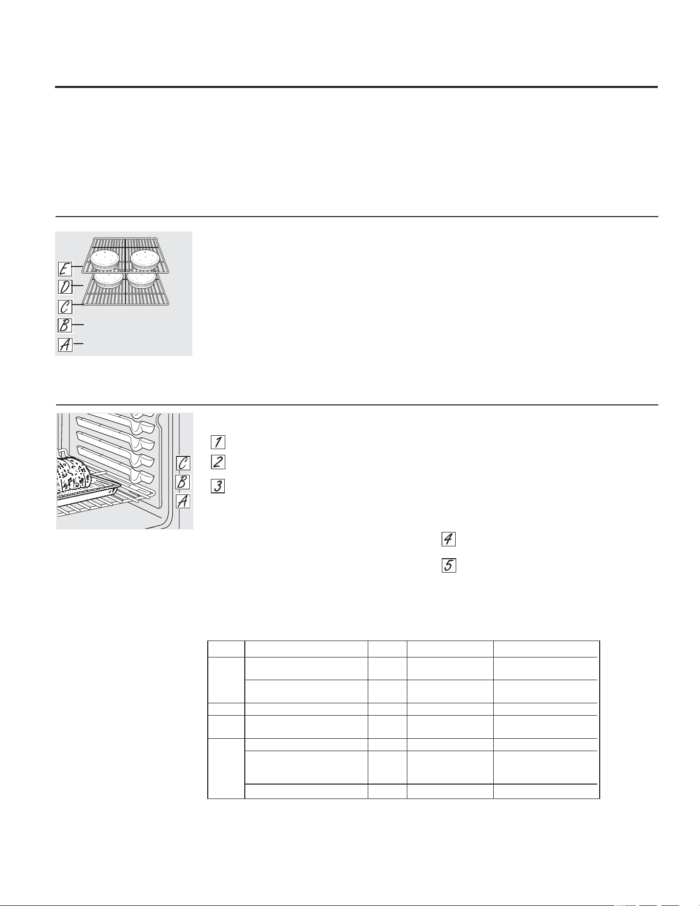
3UHKHDWLQJDQG3DQ3ODFHPHQW
7RDYRLGSRVVLEOHEXUQVSODFHWKHUDFNV
LQWKHGHVLUHGSRVLWLRQEHIRUH\RXWXUQRQWKH
RYHQ
3UHKHDWWKHRYHQLIWKHUHFLSHFDOOVIRULW3UHKHDWLQJ
LVQHFHVVDU\IRUJRRGUHVXOWVZKHQEDNLQJFDNHV
FRRNLHVSDVWULHVDQGEUHDGV
,IEDNLQJIRXUFDNHOD\HUVDWWKHVDPHWLPHSODFH
WZROD\HUVRQUDFN&DQGWZROD\HUVRQUDFN(
6WDJJHUSDQVRQWKHUDFNVRRQHLVQRWGLUHFWO\
DERYHWKHRWKHU
%DNLQJUHVXOWVZLOOEHEHWWHULIIRRGLVFHQWHUHGLQ
WKHRYHQDVPXFKDVSRVVLEOH$QJHOIRRGFDNHLV
WKHH[FHSWLRQDQGVKRXOGEHSODFHGRQWKHERWWRP
RYHQUDFNSRVLWLRQ$)ROORZSDFNDJHGLUHFWLRQVRQ
SUHSDFNDJHGDQGIUR]HQIRRGVIRUSDQSODFHPHQW
3DQVVKRXOGQRWWRXFKHDFKRWKHURUWKHZDOOVRI
WKHRYHQ,I\RXQHHGWRXVHWZRUDFNVVWDJJHUWKH
SDQVVRRQHLVQRWGLUHFWO\DERYHWKHRWKHU/HDYH
DSSUR[LPDWHO\
ø´EHWZHHQSDQVDQGIURPWKH
IURQWEDFNDQGVLGHVRIRYHQZDOO
5DFNSRVLWLRQIRUEDNLQJOD\HU
FDNHV
$OXPLQXP)RLO
'RQRWXVHDOXPLQXPIRLOWROLQHRYHQERWWRPV
7KHIRLOZLOOWUDSKHDWEHORZDQGXSVHWWKH
SHUIRUPDQFHRIWKHRYHQ)RLOFDQPHOW
DQGSHUPDQHQWO\GDPDJHWKHRYHQERWWRP
'DPDJHIURPLPSURSHUXVHRIDOXPLQXPIRLOLV
QRWFRYHUHGE\WKHSURGXFWZDUUDQW\
)RLOPD\EHXVHGWRFDWFKVSLOOVE\SODFLQJD
VKHHWRQDORZHUUDFNVHYHUDOLQFKHVEHORZ
WKHIRRG'RQRWXVHPRUHIRLOWKDQQHFHVVDU\
DQGQHYHUHQWLUHO\FRYHUDQRYHQUDFNZLWK
DOXPLQXPIRLO.HHSIRLODWOHDVWµIURP
RYHQZDOOVWRSUHYHQWSRRUKHDWFLUFXODWLRQ
5RDVWLQJ*XLGH
0HDW 2YHQ7HPS ,QWHUQDO7HPS
%HHI 5LE5RDVWWROEV 5DUH ) )
%RQH,QDQG%RQHOHVV 0HGLXP ) )
%HHI7HQGHUORLQWROEV 5DUH ) )
%HHI7HQGHUORLQWROEV 5DUH ) )
3RUN %RQH,Q%RQHOHVVWROEV ) )
/DPE %RQH,QWROEV 0HGLXP ) )
%RQHOHVVWROEV 0HGLXP ) )
3RXOWU\ :KROH&KLFNHQWROEV ) )
7XUNH\:KROH
8QVWXIIHGWROEV ) ²)
8QVWXIIHGWROEV ) ²)
7XUNH\%UHDVWWROEV ) )
6WXIIHGELUGVJHQHUDOO\UHTXLUH²PLQXWHVDGGLWLRQDOURDVWLQJWLPH6KLHOGOHJVDQGEUHDVWZLWKIRLOWR
SUHYHQWRYHUEURZQLQJDQGGU\LQJRIVNLQ
8VLQJWKHRYHQ
+RZWR6HWWKH2YHQIRU%URLOLQJ
8VH/2%URLO WRFRRNIRRGVVXFKDVSRXOWU\
RUWKLFNFXWVRIPHDWWKRURXJKO\ZLWKRXW
RYHUEURZQLQJWKHP
3ODFHWKHPHDWRUILVKRQDEURLOHUJULGLQD
EURLOHUSDQGHVLJQHGIRUEURLOLQJ
)ROORZVXJJHVWHGUDFNSRVLWLRQVLQWKH
%URLOLQJ*XLGH
7RXFKWKH%52,/+,/2 SDGRQFHIRU+,
%URLO
7RFKDQJHWR/2%URLOWRXFKWKH
%52,/+,/2SDGDJDLQ
7RXFKWKH67$57SDG
:KHQEURLOLQJLVILQLVKHGWRXFKWKH
&/($52))SDG
7KHVL]HZHLJKWWKLFNQHVV
VWDUWLQJWHPSHUDWXUH
DQG\RXUSUHIHUHQFH
RIGRQHQHVVZLOODIIHFWEURLOLQJ
WLPHV7KLVJXLGH
LVEDVHGRQPHDWVDW
UHIULJHUDWRUWHPSHUDWXUH
7KH86'HSDUWPHQWRI
$JULFXOWXUHVD\V´5DUHEHHILV
SRSXODUEXW\RXVKRXOGNQRZWKDW
FRRNLQJLWWRRQO\)PHDQV
VRPHIRRGSRLVRQLQJRUJDQLVPV
PD\VXUYLYHµ6RXUFH6DIH)RRG
%RRN<RXU.LWFKHQ*XLGH86'$
5HY-XQH
%URLOLQJ*XLGH
/HDYHWKHGRRURSHQWRWKHEURLOVWRS
SRVLWLRQ7KHGRRUVWD\VRSHQE\
LWVHOI\HWWKHSURSHUWHPSHUDWXUHLV
PDLQWDLQHGLQWKHRYHQ
3UHKHDWWKHEURLOHUIRUPLQXWHVWRLPSURYHSHUIRUPDQFH
7\SHRU
)RRG 'RQHQHVV 7KLFNQHVV 5DFN3RVLWLRQ &RPPHQWV
%HHI 5DUH) 6WHDNV² (RU)IRRGVKRXOGEHµ 6WHDNVOHVVWKDQµ
µWKLFN WRµIURPEURLOHOHPHQW WKLFNDUHGLIILFXOWWR
FRRNUDUH7KH\FRRN
0HGLXP) 6WHDNV² (IRRGVKRXOGEHµ WKURXJKEHIRUHEURZQLQJ
µWRµWKLFN WRµIURPEURLOHOHPHQW 7RSUHYHQWFXUOLQJRI
PHDWVODVKIDWDWµ
:HOO'RQH) 6WHDNV² 'RU(IRRGVKRXOGEHµ LQWHUYDOV
µWRµWKLFN WRµIURPEURLOHOHPHQW
RU*URXQG%HHI3DWWLHV
&KLFNHQ %UHDVWERQHOHVV &IRRGVKRXOGEHµ %URLOVNLQVLGHGRZQ
WRµIURPEURLOHOHPHQW ILUVW
%UHDVWERQHLQ &IRRGVKRXOGEHµ
WRµIURPEURLOHOHPHQW
)LVK)LOOHWV µWRµWKLFN 'RU(IRRGVKRXOGEHµ +DQGOHDQGWXUQYHU\
WRµIURPEURLOHOHPHQW FDUHIXOO\
3RUN&KRSV :HOO'RQH) µWKLFN 'IRRGVKRXOGEHµ 7RSUHYHQWFXUOLQJRI
WRµIURPEURLOHOHPHQW PHDWVODVKIDWDWµ
LQWHUYDOV
,I\RXUUDQJHLVFRQQHFWHGWRYROWVUDUHVWHDNVPD\EHEURLOHGE\SUHKHDWLQJWKH
EURLOHUDQGSRVLWLRQLQJWKHRYHQUDFNRQHSRVLWLRQKLJKHU

7R$GMXVWWKH7KHUPRVWDW
7RXFKWKH%52,/+,/2DQG%$.(SDGVDW
WKHVDPHWLPHXQWLOWKHGLVSOD\VKRZV6)
7RXFKWKH%$.(SDG$QXPEHUVKRZVLQ
WKHGLVSOD\
7KHRYHQWHPSHUDWXUHFDQEHDGMXVWHGXS
WR)KRWWHURU)FRROHU7RXFK
WKHQXPEHUSDGVWKHVDPHZD\\RXUHDG
WKHP)RUH[DPSOHWRFKDQJHWKHRYHQ
WHPSHUDWXUH)WRXFKDQG
7RXFKWKH%$.(SDGDJDLQWRDOWHUQDWH
EHWZHHQLQFUHDVLQJDQGGHFUHDVLQJWKH
RYHQWHPSHUDWXUH
:KHQ\RXKDYHPDGHWKHDGMXVWPHQW
WRXFKWKH67$57 SDGWRJREDFNWRWKHWLPH
RIGD\GLVSOD\8VH\RXURYHQDV\RXZRXOG
QRUPDOO\
$GMXVWWKHRYHQWKHUPRVWDW³'RLW\RXUVHOI *($SSOLDQFHVFRP
<RXPD\ILQGWKDW\RXUQHZRYHQFRRNVGLIIHUHQWO\WKDQWKHRQHLWUHSODFHG8VH\RXUQHZRYHQIRUDIHZZHHNVWR
EHFRPHPRUHIDPLOLDUZLWKLW,I\RXVWLOOWKLQN\RXUQHZRYHQLVWRRKRWRUWRRFROG\RXFDQDGMXVWWKHWKHUPRVWDW
\RXUVHOI
'RQRWXVHWKHUPRPHWHUVVXFKDVWKRVHIRXQGLQJURFHU\VWRUHVWRFKHFNWKHWHPSHUDWXUHVHWWLQJRI\RXURYHQ7KHVH
WKHUPRPHWHUVPD\YDU\²GHJUHHV
127(7KLVDGMXVWPHQWZLOORQO\DIIHFWEDNLQJDQGURDVWLQJWHPSHUDWXUHVLWZLOOQRWDIIHFWEURLOLQJRUVHOIFOHDQLQJ
WHPSHUDWXUHV7KHDGMXVWPHQWZLOOEHUHWDLQHGLQPHPRU\DIWHUDSRZHUIDLOXUH
7KHW\SHRIPDUJDULQHZLOODIIHFWEDNLQJSHUIRUPDQFH
0RVWUHFLSHVIRUEDNLQJKDYHEHHQGHYHORSHGXVLQJKLJKIDWSURGXFWVVXFKDVEXWWHURUPDUJDULQHIDW
,I\RXGHFUHDVHWKHIDWWKHUHFLSHPD\QRWJLYHWKHVDPHUHVXOWVDVZLWKDKLJKHUIDWSURGXFW
5HFLSHIDLOXUHFDQUHVXOWLIFDNHVSLHVSDVWULHVFRRNLHVRUFDQGLHVDUHPDGHZLWKORZIDWVSUHDGV
7KHORZHUWKHIDWFRQWHQWRIDVSUHDGSURGXFWWKHPRUHQRWLFHDEOHWKHVHGLIIHUHQFHVEHFRPH
)HGHUDOVWDQGDUGVUHTXLUHSURGXFWVODEHOHG´PDUJDULQHµWRFRQWDLQDWOHDVWIDWE\ZHLJKW/RZIDWVSUHDGVRQWKHRWKHUKDQG
FRQWDLQOHVVIDWDQGPRUHZDWHU7KHKLJKPRLVWXUHFRQWHQWRIWKHVHVSUHDGVDIIHFWVWKHWH[WXUHDQGIODYRURIEDNHGJRRGV)RUEHVW
UHVXOWVZLWK\RXUROGIDYRULWHUHFLSHVXVHPDUJDULQHEXWWHURUVWLFNVSUHDGVFRQWDLQLQJDWOHDVWYHJHWDEOHRLO
8VLQJWKHFRQYHFWLRQRYHQRQVRPHPRGHOV
%HFDXVHKHDWHGDLULVFLUFXODWHGHYHQO\
WKURXJKRXWWKHRYHQIRRGVFDQEHEDNHGZLWK
H[FHOOHQWUHVXOWVXVLQJPXOWLSOHUDFNV
0XOWLUDFNEDNLQJPD\LQFUHDVHFRRNWLPHV
VOLJKWO\IRUVRPHIRRGVEXWWKHRYHUDOOUHVXOW
LVWLPHVDYHG&RRNLHVPXIILQVELVFXLWVDQG
RWKHUTXLFNEUHDGVJLYHYHU\JRRGUHVXOWVZLWK
PXOWLUDFNEDNLQJ
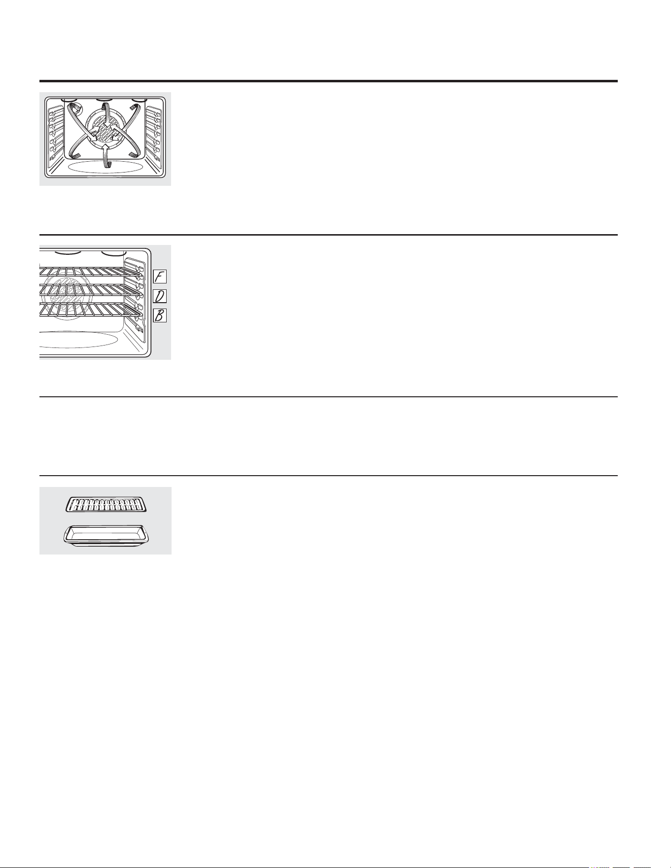
:KHQEDNLQJRQUDFNVSODFHRQHUDFNLQWKH
VHFRQG%SRVLWLRQDQRWKHUUDFNLQWKHIRXUWK
'SRVLWLRQDQGWKHWKLUGUDFNLQWKHVL[WK)
SRVLWLRQ
)RUWZRUDFNEDNLQJSODFHRQHUDFNLQWKH
VHFRQG%UDFNSRVLWLRQ3ODFHWKHRWKHUUDFNLQ
WKHILIWK(UDFNSRVLWLRQ
0XOWL5DFN&RQYHFWLRQ%DNLQJRQVRPHPRGHOV
0XOWLUDFNSRVLWLRQ
:KHQFRQYHFWLRQEDNLQJZLWKRQO\UDFNSODFH
WKHIRRGVRWKDWLWLVFHQWHUHGLQWKHRYHQ
5DFN&RQYHFWLRQ%DNLQJRQVRPHPRGHOV
&RQYHFWLRQ)DQ2SHUDWLRQ
,QDFRQYHFWLRQRYHQDIDQFLUFXODWHVKRWDLU
RYHUXQGHUDQGDURXQGWKHIRRG
7KLVFLUFXODWLQJKRWDLULVHYHQO\GLVWULEXWHG
WKURXJKRXWWKHRYHQFDYLW\$VDUHVXOWIRRGV
DUHHYHQO\FRRNHGDQGEURZQHG³RIWHQLQOHVV
WLPHZLWKFRQYHFWLRQKHDW
127(2QVRPHPRGHOVWKHIDQLVGHVLJQHG
WRURWDWHLQERWKGLUHFWLRQVZLWKDSDXVHLQ
EHWZHHQ7KLVLVQRUPDO
7KHFRQYHFWLRQIDQVKXWVRIIZKHQWKHRYHQ
GRRULVRSHQHG'2127OHDYHWKHGRRURSHQ
IRUORQJSHULRGVRIWLPHZKLOHXVLQJFRQYHFWLRQ
FRRNLQJRU\RXPD\VKRUWHQWKHOLIHRIWKH
FRQYHFWLRQKHDWLQJHOHPHQW
*ULG
%URLOHUSDQ
*RRGIRUODUJHWHQGHUFXWVRIPHDW
XQFRYHUHG
7KHFRQYHFWLRQIDQFLUFXODWHVWKHKHDWHGDLU
HYHQO\RYHUDQGDURXQGWKHIRRG0HDWDQG
SRXOWU\DUHEURZQHGRQDOOVLGHVDVLIWKH\ZHUH
FRRNHGRQDURWLVVHULH7KHKHDWHGDLUVHDOVLQ
MXLFHVTXLFNO\IRUDPRLVWDQGWHQGHUSURGXFW
ZKLOHDWWKHVDPHWLPHFUHDWLQJDULFKJROGHQ
EURZQH[WHULRU
:KHQ\RXDUHFRQYHFWLRQURDVWLQJLWLV
LPSRUWDQWWKDW\RXXVHDEURLOHUSDQDQGJULG
IRUEHVWFRQYHFWLRQURDVWLQJUHVXOWV7KHSDQLV
XVHGWRFDWFKJUHDVHVSLOOVDQGWKHJULGLVXVHG
WRSUHYHQWJUHDVHVSDWWHUV
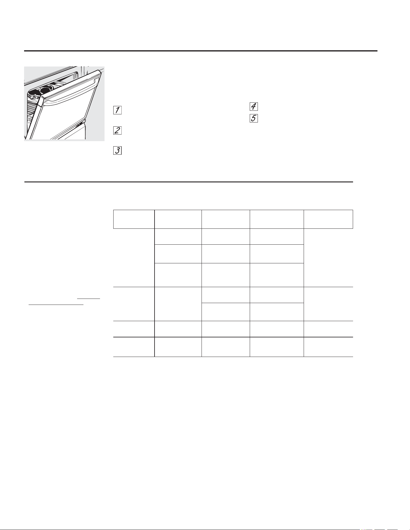
&RQYHFWLRQ5RDVWRQVRPHPRGHOV
7RXFKWKH&219(&7,21%$.(SDGRQ
VRPHPRGHOV
RQFHIRUPXOWLUDFN
FRQYHFWLRQEDNLQJ
6HHWKH0XOWL5DFN
&RQYHFWLRQ%DNLQJVHFWLRQ
7RXFKWKH&219(&7,21%$.(SDGRQ
VRPHPRGHOVWZLFHIRUUDFNFRQYHFWLRQ
EDNLQJ6HHWKH5DFN&RQYHFWLRQ%DNLQJ
VHFWLRQ
7RXFKWKH&219(&7,2152$67SDGIRU
FRQYHFWLRQURDVWLQJRQVRPHPRGHOV
7RXFKWKHQXPEHUSDGVWRVHWWKHRYHQ
WHPSHUDWXUH
7RXFKWKH67$57SDG
127(,IWKH$XWR5HFLSH
&RQYHUVLRQ)HDWXUH
LVRQLWZLOODXWRPDWLFDOO\UHGXFHWKHVHWUHJXODU
EDNLQJWHPSHUDWXUHE\DSSUR[LPDWHO\)
WRWKHDSSURSULDWHFRQYHFWLRQWHPSHUDWXUH
LQFRQYHFWLRQEDNHPRGH6HH$XWR5HFLSH
&RQYHUVLRQLQWKH6SHFLDO)HDWXUHVVHFWLRQ
7RFKDQJHWKHRYHQWHPSHUDWXUHWRXFKWKH
&219(&7,21%$.(RU&219(&7,2152$67
SDGDQGWKHQWKHQXPEHUSDGVWRVHWWKHQHZ
WHPSHUDWXUH
:KHQWKHRYHQVWDUWVWRKHDWWKHFKDQJLQJ
WHPSHUDWXUHVWDUWLQJDW)ZLOOEHGLVSOD\HG
:KHQRYHQUHDFKHVWKHWHPSHUDWXUH\RXVHW
EHHSVZLOOVRXQG
7RXFK&/($52))SDGZKHQILQLVKHG
<RXZLOOKHDUDIDQZKLOHFRRNLQJZLWK
FRQYHFWLRQ7KHIDQZLOOVWRSZKHQWKHGRRULV
RSHQHGEXWWKHKHDWZLOOQRWWXUQRII
<RXPD\KHDUWKHRYHQFOLFNLQJGXULQJ
EDNLQJ7KLVLVQRUPDO
&RRNZDUHIRU&RQYHFWLRQ&RRNLQJ
%HIRUHXVLQJ\RXUFRQYHFWLRQRYHQFKHFNWRVHH
LI\RXUFRRNZDUHOHDYHVURRPIRUDLUFLUFXODWLRQ
LQWKHRYHQ,I\RXDUHEDNLQJZLWKVHYHUDOSDQV
OHDYHVSDFHEHWZHHQWKHP$OVREHVXUHWKH
SDQVGRQRWWRXFKHDFKRWKHURUWKHZDOOVRIWKH
RYHQ
3DSHUDQG3ODVWLF
+HDWUHVLVWDQWSDSHUDQGSODVWLFFRQWDLQHUVWKDW
DUHUHFRPPHQGHGIRUXVHLQUHJXODUEDNLQJFDQ
DOVREHXVHGIRUFRQYHFWLRQEDNLQJEXWVKRXOG
QRWEHXVHGDWWHPSHUDWXUHVKLJKHUWKDQWKH
WHPSHUDWXUHUHFRPPHQGHGE\WKHFRRNZDUH
PDQXIDFWXUHU3ODVWLFFRRNZDUHWKDWLVKHDW
UHVLVWDQWWRWHPSHUDWXUHVRI)FDQDOVREH
XVHG
0HWDODQG*ODVV
$Q\W\SHRIFRRNZDUHZLOOZRUNLQ\RXU
FRQYHFWLRQRYHQKRZHYHUPHWDOSDQVKHDWWKH
IDVWHVWDQGDUHUHFRPPHQGHGIRUFRQYHFWLRQ
EDNLQJ
'DUNHQHGRUPDWWHILQLVKHGSDQVZLOOEDNH
IDVWHUWKDQVKLQ\SDQV
*ODVVRUFHUDPLFSDQVFRRNPRUHVORZO\
)RUUHFLSHVOLNHRYHQEDNHGFKLFNHQXVHDSDQ
ZLWKORZVLGHV+RWDLUFDQQRWFLUFXODWHZHOO
DURXQGIRRGLQDSDQZLWKKLJKVLGHV
+RZWR6HWWKH2YHQIRU&RQYHFWLRQ%DNLQJRU5RDVWLQJ
OR
:KHQEDNLQJFRRNLHV\RXZLOOJHW
WKHEHVWUHVXOWVLI\RXXVHDIODW
FRRNLHVKHHWLQVWHDGRIDSDQZLWK
ORZVLGHV
*($SSOLDQFHVFRP
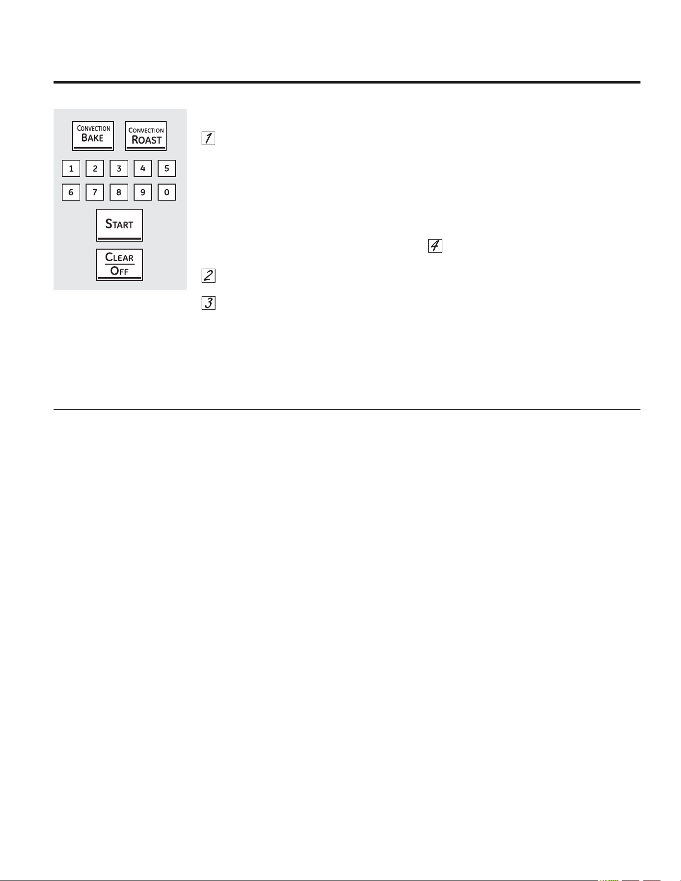
8VLQJWKHSUREHRQVRPHPRGHOV
,QVHUWWKHSUREHIXOO\LQWRWKHIRRG
3OXJWKHSUREHLQWRWKHRXWOHWLQWKHRYHQ
0DNHVXUHLW·VSXVKHGDOOWKHZD\LQ&ORVH
WKHRYHQGRRU0DNHVXUHWKHSUREHFDEOH
LVQRWWRXFKLQJWKHEURLOHOHPHQW
7RXFKWKH352%(SDG'LVSOD\ZLOOVKRZ
´6HW3UREHµ
7RXFKWKHQXPEHUSDGVWRVHWWKHGHVLUHG
LQWHUQDOIRRGRUPHDWWHPSHUDWXUH7KH
PD[LPXPLQWHUQDOWHPSHUDWXUHIRUWKH
IRRGWKDW\RXFDQVHWLV)
7RXFKWKH%$.(RU&219(&7,21SDG
7RXFKWKHQXPEHUSDGVWRVHWWKHGHVLUHG
RYHQWHPSHUDWXUH
7RXFKWKH67$57SDG
7KHGLVSOD\ZLOOIODVKLIWKHSUREHLVLQVHUWHG
LQWRWKHRXWOHWDQG\RXKDYHQRWVHWDSUREH
WHPSHUDWXUHDQGWRXFKHGWKH67$57SDG
7RXFKWKH352%(SDGWRUHFDOOWKHSUREH
WHPSHUDWXUHRU%$.(RU&219(&7,21SDG
WRUHFDOOWKHRYHQWHPSHUWXUH)RUWKHSUREH
WHPSHUDWXUHDIWHUWKHLQWHUQDOWHPSHUDWXUH
RIWKHIRRGUHDFKHV)WKHFKDQJLQJ
WHPSHUDWXUHZLOOEHVKRZQLQWKHGLVSOD\
:KHQWKHLQWHUQDOWHPSHUDWXUHRIWKHIRRG
UHDFKHVWKHQXPEHU\RXKDYHVHWWKH
SUREHDQGWKHRYHQWXUQRIIDQGWKHRYHQ
FRQWUROVLJQDOV7RVWRSWKHVLJQDOWRXFK
WKH&/($52))SDG8VHKRWSDGVWR
UHPRYHWKHSUREHIURPWKHIRRG'RQRW
XVHWRQJVWRSXOORQLW³WKH\PLJKW
GDPDJHLW
,IWKHSUREHLVUHPRYHGIURPWKHRYHQ
ZKLOHSUREHFRRNLQJWKHRYHQZLOOQRW
DXWRPDWLFDOO\WXUQRII
7RFKDQJHWKHRYHQWHPSHUDWXUHGXULQJ
WKH%DNH5RDVWF\FOHWRXFKWKH%$.(RU
&219(&7,21SDGDQGWKHQWKHQXPEHUSDGV
WRVHWWKHQHZWHPSHUDWXUH
<RXFDQXVHWKH.LWFKHQ7LPHUHYHQWKRXJK
\RXFDQQRWXVHWLPHGRYHQRSHUDWLRQVZKLOH
XVLQJWKHSUREH
7RSUHYHQWEXUQVGRQRWXQSOXJWKHSUREHIURP
WKHRYHQRXWOHWXQWLOWKHRYHQKDVFRROHG
8VHRISUREHVRWKHUWKDQWKHRQHSURYLGHGZLWK
WKLVSURGXFWPD\UHVXOWLQGDPDJHWRWKHSUREH
RURYHQFRQWURO
8VHWKHKDQGOHVRIWKHSUREHDQGSOXJZKHQ
LQVHUWLQJDQGUHPRYLQJWKHPIURPWKHIRRGDQG
RXWOHW
7RDYRLGGDPDJLQJ\RXUSUREHGRQRWXVH
WRQJVWRSXOORQWKHFDEOHZKHQUHPRYLQJLW
7RDYRLGEUHDNLQJWKHSUREHPDNHVXUHIRRG
LVFRPSOHWHO\GHIURVWHGEHIRUHLQVHUWLQJ
$IWHUSUHSDULQJWKHPHDWDQGSODFLQJLWRQ
DWULYHWRUDEURLOHUSDQJULGIROORZWKHVH
GLUHFWLRQVIRUSURSHUSUREHSODFHPHQW
,QVHUWWKHSUREHFRPSOHWHO\LQWRWKHPHDW,W
VKRXOGQRWWRXFKERQHIDWRUJULVWOH
127()DLOXUHWRIXOO\LQVHUWWKHSUREHLQWRWKH
PHDWPD\UHVXOWLQSRRUFRRNLQJSHUIRUPDQFH
EHFDXVHWKHSUREHZLOOVHQVHWKHRYHQDLUYV
WKHIRRGWHPSHUDWXUH
1HYHUOHDYH\RXUSUREHLQVLGHWKHRYHQ
GXULQJDVHOIFOHDQLQJRUEURLOF\FOH
'RQRWVWRUHWKHSUREHLQWKHRYHQ
)RUURDVWVZLWKQRERQHLQVHUWWKHSUREHLQWR
WKHPHDWLHVWSDUWRIWKHURDVW)RUERQHLQKDP
RUODPELQVHUWWKHSUREHLQWRWKHFHQWHURIWKH
ORZHVWODUJHPXVFOH
,QVHUWWKHSUREHLQWRWKHFHQWHURIGLVKHVVXFK
DVPHDWORDIRUFDVVHUROHV
,QVHUWWKHSUREHLQWRWKHPHDWLHVWSDUWRIWKH
LQQHUWKLJKIURPEHORZDQGSDUDOOHOWRWKHOHJRI
DZKROHWXUNH\
127(6HOIFOHDQDQG%URLOVHWWLQJVZLOOQRWZRUN
LIWKHWHPSHUDWXUHSUREHLVSOXJJHGLQ
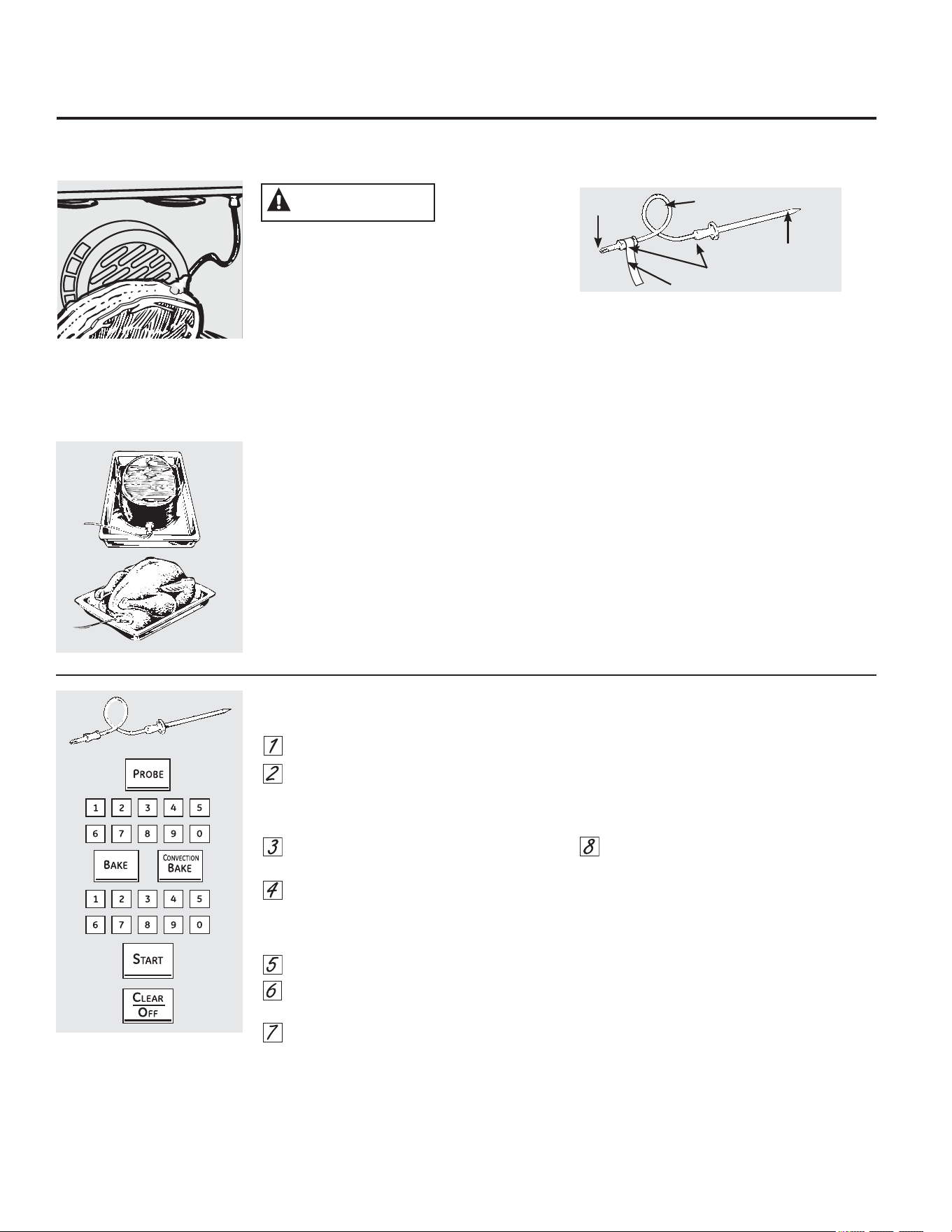
7KHWHPSHUDWXUHSUREHKDVD
VNHZHUOLNHSUREHDWRQHHQGDQG
DSOXJDWWKHRWKHUHQGWKDWJRHV
LQWRWKHRXWOHWLQWKHRYHQ
+RZWR6HWWKH2YHQ)RU%DNLQJ5RDVWLQJ:KHQ8VLQJWKH3UREH
RQVRPHPRGHOV
OR
3OXJ
&DEOH
+DQGOHV
3UREH
)RUPDQ\IRRGVHVSHFLDOO\URDVWVDQGSRXOWU\LQWHUQDOIRRGWHPSHUDWXUHLVWKHEHVWWHVWIRUGRQHQHVV7KHWHPSHUDWXUH
SUREHWDNHVWKHJXHVVZRUNRXWRIURDVWLQJE\FRRNLQJIRRGVWRWKHH[DFWGRQHQHVV\RXZDQW
5HDGDQGUHPRYHODEHO
&$87,21
8VLQJWKHWLPHGEDNLQJDQGURDVWLQJIHDWXUHV
*($SSOLDQFHVFRP
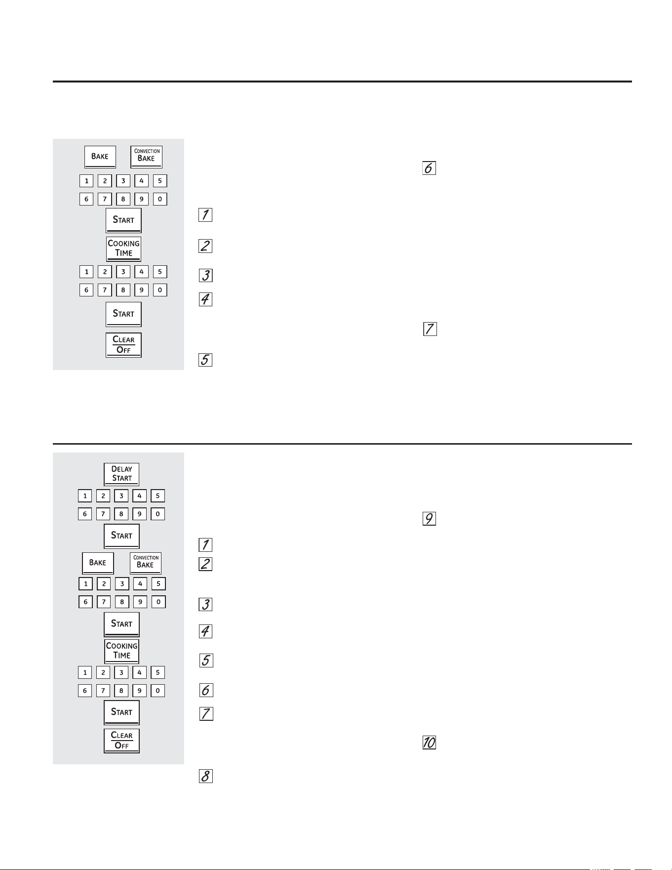
+RZWR6HWDQ,PPHGLDWH6WDUWDQG$XWRPDWLF6WRS
7KHRYHQZLOOWXUQRQLPPHGLDWHO\DQGFRRN
IRUDVHOHFWHGOHQJWKRIWLPH$WWKHHQG
RIWKHFRRNLQJWLPHWKHRYHQZLOOWXUQRII
DXWRPDWLFDOO\
7RXFKWKH%$.(RU&219(&7,21%$.(
SDGRURWKHUGHVLUHGFRRNLQJIXQFWLRQ
7RXFKWKHQXPEHUSDGVWRVHWWKHGHVLUHG
RYHQWHPSHUDWXUH
7RXFKWKH67$57SDG
7RXFKWKH&22.,1*7,0(SDG
127(,I\RXUUHFLSHUHTXLUHVSUHKHDWLQJ\RX
PD\QHHGWRDGGDGGLWLRQDOWLPHWRWKHOHQJWKRI
WKHFRRNLQJWLPH
7RXFKWKHQXPEHUSDGVWRVHWWKHGHVLUHG
OHQJWKRIFRRNLQJWLPH7KHPLQLPXP
FRRNLQJWLPH\RXFDQVHWLVPLQXWH
7KHRYHQWHPSHUDWXUHWKDW\RXVHWDQG
WKHFRRNLQJWLPHWKDW\RXHQWHUHGZLOOEH
LQWKHGLVSOD\
7RXFKWKH67$57SDG
7KHRYHQZLOOWXUQ21DQGWKHGLVSOD\ZLOOVKRZ
WKHFRRNLQJWLPHFRXQWGRZQDQGWKHFKDQJLQJ
WHPSHUDWXUHVWDUWLQJDW)7KHWHPSHUDWXUH
GLVSOD\ZLOOVWDUWWRFKDQJHRQFHWKHRYHQ
WHPSHUDWXUHUHDFKHV):KHQWKHRYHQ
UHDFKHVWKHWHPSHUDWXUH\RXVHWEHHSVZLOO
VRXQG
7KHRYHQZLOOFRQWLQXHWRFRRNIRUWKHVHW
DPRXQWRIWLPHWKHQWXUQRIIDXWRPDWLFDOO\
XQOHVVWKH:$50IHDWXUHZDVVHW6HHWKH+RZ
WR6HWWKH2YHQIRU:DUPLQJVHFWLRQ
7RXFKWKH&/($52))SDGWRFOHDUWKH
GLVSOD\LIQHFHVVDU\5HPRYHWKHIRRGIURP
WKHRYHQ5HPHPEHUHYHQWKRXJKWKH
RYHQWXUQVRIIDXWRPDWLFDOO\IRRGOHIWLQ
WKHRYHQZLOOFRQWLQXHFRRNLQJDIWHUWKH
RYHQWXUQVRII
OR
+RZWR6HWD'HOD\HG6WDUWDQG$XWRPDWLF6WRS
7KHRYHQZLOOWXUQRQDWWKHWLPHRIGD\\RXVHW
FRRNIRUDVSHFLILFOHQJWKRIWLPHDQGWKHQWXUQ
RIIDXWRPDWLFDOO\
0DNHVXUHWKHFORFNVKRZVWKHFRUUHFWWLPHRI
GD\
7RXFKWKH'(/$<67$57SDG
7RXFKWKHQXPEHUSDGVWRVHWWKHWLPHRI
GD\\RXZDQWWKHRYHQWRWXUQRQDQG
VWDUWFRRNLQJ
7RXFKWKH67$57SDG
7RXFKWKH%$.(RU&219(&7,21%$.(
SDGRURWKHUGHVLUHGFRRNLQJIXQFWLRQ
7RXFKWKHQXPEHUSDGVWRVHWWKHGHVLUHG
RYHQWHPSHUDWXUH
7RXFKWKH67$57SDG
7RXFKWKH&22.,1*7,0(SDG
127(,I\RXUUHFLSHUHTXLUHVSUHKHDWLQJ\RX
PD\QHHGWRDGGDGGLWLRQDOWLPHWRWKHOHQJWK
RIWKHFRRNLQJWLPH
7RXFKWKHQXPEHUSDGVWRVHWWKHGHVLUHG
OHQJWKRIFRRNLQJWLPH7KHPLQLPXP
FRRNLQJWLPH\RXFDQVHWLVPLQXWH
7KHRYHQWHPSHUDWXUHWKDW\RXVHWDQG
WKHFRRNLQJWLPHWKDW\RXHQWHUHGZLOOEH
LQWKHGLVSOD\
7RXFKWKH67$57SDG
127(,I\RXZRXOGOLNHWRFKHFNWKHWLPHV
\RXKDYHVHWWRXFKWKH'(/$<67$57SDGWR
FKHFNWKHVWDUWWLPH\RXKDYHVHWRUWRXFKWKH
&22.7,0(SDGWRFKHFNWKHOHQJWKRIFRRNLQJ
WLPH\RXKDYHVHW
:KHQWKHRYHQWXUQV21DWWKHWLPHRIGD\
\RXVHWWKHGLVSOD\ZLOOVKRZWKHFRRNLQJWLPH
FRXQWGRZQDQGWKHFKDQJLQJWHPSHUDWXUH
VWDUWLQJDW)7KHWHPSHUDWXUHGLVSOD\ZLOO
VWDUWWRFKDQJHRQFHWKHRYHQWHPSHUDWXUH
UHDFKHV):KHQWKHRYHQUHDFKHVWKH
WHPSHUDWXUH\RXVHWEHHSVZLOOVRXQG
7KHRYHQZLOOFRQWLQXHWRFRRNIRUWKHVHW
DPRXQWRIWLPHWKHQWXUQRIIDXWRPDWLFDOO\
XQOHVVWKH:$50IHDWXUHZDVVHW6HHWKH+RZ
WR6HWWKH2YHQIRU:DUPLQJVHFWLRQ
7RXFKWKH&/($52))SDGWRFOHDUWKH
GLVSOD\LIQHFHVVDU\5HPRYHWKHIRRGIURP
WKHRYHQ5HPHPEHUHYHQWKRXJKWKH
RYHQWXUQVRIIDXWRPDWLFDOO\IRRGOHIWLQ
WKHRYHQZLOOFRQWLQXHFRRNLQJDIWHUWKH
RYHQWXUQVRII
OR
127()RRGVWKDWVSRLOHDVLO\³VXFKDVPLONHJJVILVKVWXIILQJVSRXOWU\DQGSRUN³VKRXOGQRWEHDOORZHGWRVLWIRUPRUH
WKDQKRXUEHIRUHRUDIWHUFRRNLQJ5RRPWHPSHUDWXUHSURPRWHVWKHJURZWKRIKDUPIXOEDFWHULD
%HVXUHWKDWWKHRYHQOLJKWLVRIIEHFDXVHKHDWIURPWKHEXOEZLOOVSHHGKDUPIXOEDFWHULDJURZWK
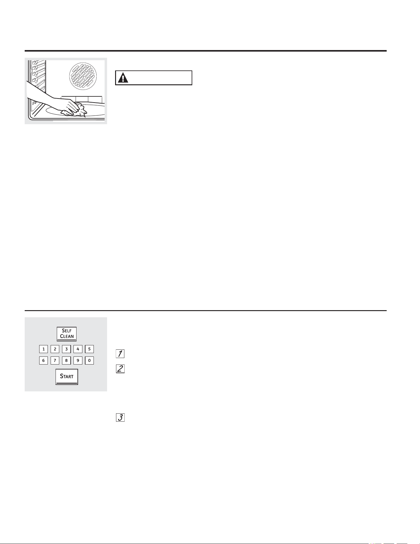
8VLQJWKHVHOIFOHDQLQJRYHQ
:LSHXSKHDY\VRLORQWKHRYHQ
ERWWRP
%HIRUHD6HOI&OHDQ&\FOH
),5(+$=$5':LSHJUHDVHDQGKHDY\VRLO
IURPWKHRYHQERWWRPEHIRUHVHOIFOHDQLQJ
)DLOXUHWRGRVRPD\UHVXOWLQDQRYHQILUH
:HUHFRPPHQGYHQWLQJ\RXUNLWFKHQZLWK
DQRSHQZLQGRZRUXVLQJDYHQWLODWLRQIDQRU
KRRGGXULQJWKHILUVWVHOIFOHDQF\FOH
5HPRYHDQ\EURLOHUSDQEURLOHUJULGSUREH
DOOFRRNZDUHDQGDQ\DOXPLQXPIRLOIURPWKH
RYHQ
127(
,I\RXURYHQLVHTXLSSHGZLWKVKLQ\VLOYHU
FRORUHGRYHQUDFNVZHUHFRPPHQG
\RXUHPRYHWKHPEHIRUH\RXEHJLQWKH
VHOIFOHDQF\FOH7KH\PD\UHPDLQLQWKH
RYHQGXULQJWKHVHOIFOHDQF\FOHEXWWKH\
ZLOOGDUNHQORVHWKHLUOXVWHUDQGEHFRPH
KDUGWRVOLGH
,I\RXURYHQLVHTXLSSHGZLWKJUD\
SRUFHODLQFRDWHGRYHQUDFNVWKH\PD\EH
OHIWLQWKHRYHQGXULQJWKHVHOIFOHDQF\FOH
6RLORQWKHIURQWIUDPHRIWKHUDQJHDQG
RXWVLGHWKHJDVNHWRQWKHGRRUZLOOQHHGWR
EHFOHDQHGE\KDQG&OHDQWKHVHDUHDVZLWK
KRWZDWHUVRDSILOOHGVWHHOZRROSDGVRU
FOHDQVHUVVXFKDV6RIW6FUXE
5LQVHZHOOZLWK
FOHDQZDWHUDQGGU\
'RQRWFOHDQWKHJDVNHW7KHILEHUJODVV
PDWHULDORIWKHRYHQGRRUJDVNHWFDQQRW
ZLWKVWDQGDEUDVLRQ,WLVHVVHQWLDOIRUWKH
JDVNHWWRUHPDLQLQWDFW,I\RXQRWLFHLW
EHFRPLQJZRUQRUIUD\HGUHSODFHLW
0DNHVXUHWKHRYHQOLJKWEXOEFRYHULVLQ
SODFHDQGWKHRYHQOLJKWLVRII
,03257$177KHKHDOWKRIVRPHELUGVLV
H[WUHPHO\VHQVLWLYHWRWKHIXPHVJLYHQRII
GXULQJWKHVHOIFOHDQLQJF\FOHRIDQ\UDQJH
0RYHELUGVWRDQRWKHUZHOOYHQWLODWHGURRP
&DQDGLDQ0RGHOV2QO\
7KHVXUIDFHXQLWVDUHDXWRPDWLFDOO\GLVDEOHG
GXULQJWKHVHOIFOHDQF\FOH0DNHVXUHWKDW
DOOVXUIDFHXQLWFRQWUROVDUHWXUQHGRIIDW
DOOWLPHVGXULQJWKHVHOIFOHDQF\FOH$Q\
VXUIDFHXQLWWKDWLVVHWWRDQ´RQµSRVLWLRQ
ZKLOHWKHVHOIFOHDQF\FOHLVRSHUDWLQJZLOO
DXWRPDWLFDOO\FRPHRQDIWHUWKHVHOIFOHDQ
F\FOHLVILQLVKHGDQGFRXOGUHVXOWLQDQ´RQµ
XQDWWHQGHGVXUIDFHXQLW:DLWXQWLOWKH
VHOIFOHDQF\FOHLVILQLVKHGWRVHWDQGXVHWKH
VXUIDFHXQLWV
+RZWR6HWWKH2YHQIRU6HOI&OHDQLQJ
7KHRYHQGRRUPXVWEHFORVHGDQGDOOFRQWUROV
VHWFRUUHFWO\IRUWKHF\FOHWRZRUNSURSHUO\
7RXFKWKH6(/)&/($1 SDG
,IDWLPHRWKHUWKDQWKHGHIDXOWWLPHLV
QHHGHGXVHWKHQXPEHU SDGVDQG
HQWHUWKHGHVLUHGFOHDQWLPH
<RXFDQFKDQJHWKHFOHDQWLPHWRDQ\WLPH
EHWZHHQKRXUVDQGKRXUVGHSHQGLQJRQ
KRZGLUW\\RXURYHQLV
7RXFKWKH67$57SDG
7KHRYHQGRRUORFNVDXWRPDWLFDOO\7KH
GLVSOD\ZLOOVKRZWKHFOHDQWLPHUHPDLQLQJ
,WZLOOQRWEHSRVVLEOHWRRSHQWKHRYHQGRRU
XQWLOWKHWHPSHUDWXUHGURSVEHORZWKHORFN
WHPSHUDWXUHDQG/2&.('JRHVRIILQWKH
FRQWUROGLVSOD\
7KHZRUG/2&.('ZLOOIODVKDQGWKHZRUG
'225ZLOOGLVSOD\LI\RXVHWWKHFOHDQF\FOH
DQGIRUJHWWRFORVHWKHRYHQGRRU
7RVWRSDFOHDQF\FOHWRXFKWKH&/($5
2))SDG:KHQ/2&.('JRHVRII
LQGLFDWLQJWKHRYHQKDVFRROHGEHORZWKH
ORFNLQJWHPSHUDWXUH\RXZLOOEHDEOHWR
RSHQWKHGRRU
:$51,1*
$IWHUD6HOI&OHDQ&\FOH
<RXPD\QRWLFHVRPHZKLWHDVKLQWKHRYHQ
:LSHLWXSZLWKDGDPSFORWKDIWHUWKHRYHQ
FRROV
,IZKLWHVSRWVUHPDLQUHPRYHWKHPZLWKD
VRDSILOOHGVWHHOZRROSDGDQGULQVHWKRURXJKO\
ZLWKDYLQHJDUDQGZDWHUPL[WXUH
7KHVHGHSRVLWVDUHXVXDOO\DVDOWUHVLGXHWKDW
FDQQRWEHUHPRYHGE\WKHFOHDQF\FOH
,IWKHRYHQLVQRWFOHDQDIWHURQHFOHDQF\FOH
UHSHDWWKHF\FOH
<RXFDQQRWVHWWKHRYHQIRUFRRNLQJXQWLOWKH
RYHQLVFRROHQRXJKIRUWKHGRRUWRXQORFN
:KLOHWKHRYHQLVVHOIFOHDQLQJ\RXFDQWRXFK
&/2&.WRGLVSOD\WKHWLPHRIGD\7RUHWXUQWR
WKHFOHDQFRXQWGRZQWRXFK6(/)&/($1
6WDQGDUG5DFNV
,IWKH\EHFRPHKDUGWRVOLGHZLSHWKHLUVLGH
HGJHVDQGWKHRYHQUDFNVXSSRUWVZLWKFRRNLQJ
RLO
([WHQVLRQ5DFN
,ILWEHFRPHVGLIILFXOWWRVOLGHVHH([WHQVLRQ
5DFNLQWKH&DUHDQGFOHDQLQJVHFWLRQ'RQRW
VSUD\H[WHQVLRQUDFNZLWKFRRNLQJVSUD\RU
RWKHUOXEULFDQWVSUD\V
,ILWEHFRPHVKDUGWRUHPRYHRUUHSODFHZLSH
WKHRYHQUDFNVXSSRUWVZLWKFRRNLQJRLO'RQRW
ZLSHFRRNLQJRLORQWKHVOLGHV
127($IWHUWKHILUVWVHOIFOHDQF\FOHWKHJUD\
VWDLQOHVVVWHHOVXUIDFHVZLOOFKDQJHFRORURQ
HQDPHOHGH[WHQVLRQUDFNV7KLVLVQRUPDO,WLV
QRWUHFRPPHQGHGWRVHOIFOHDQQLFNHOH[WHQVLRQ
UDFNVDVWKHZKROHUDFNZLOOGLVFRORUEHFDXVHRI
WKHVHOIFOHDQWHPSHUDWXUHV
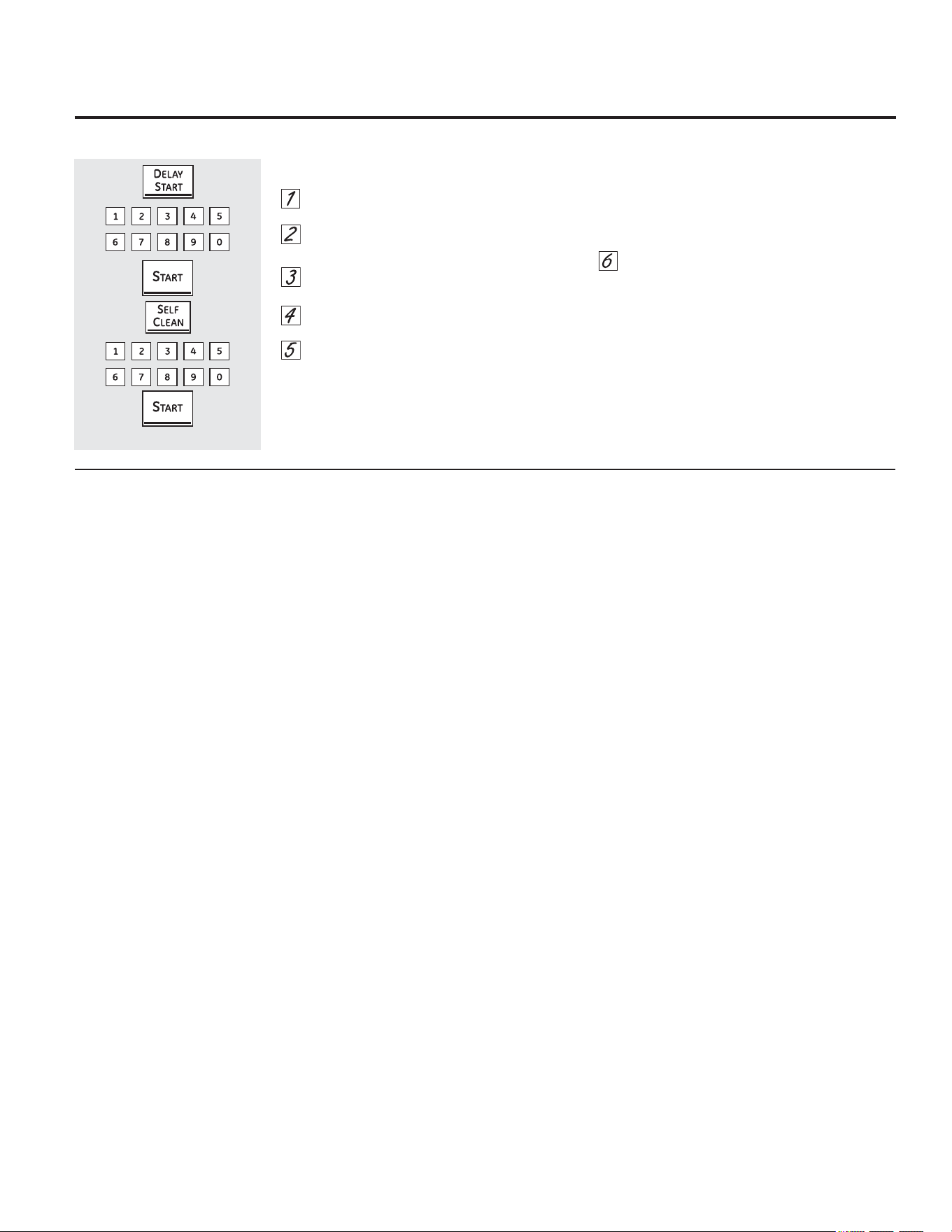
+RZWR'HOD\WKH6WDUWRI6HOI&OHDQLQJ
7RXFKWKH'(/$<67$57SDG
8VLQJWKHQXPEHUSDGVHQWHUWKHWLPHRI
GD\\RXZDQWWKHFOHDQF\FOHWRVWDUW
7RXFKWKH67$57SDG
7RXFKWKH6(/)&/($1 SDG
,IDWLPHRWKHUWKDQWKHGHIDXOWWLPHLV
QHHGHGXVHWKHQXPEHUSDGVDQGHQWHU
WKHGHVLUHGFOHDQWLPH
<RXFDQFKDQJHWKHFOHDQWLPHWRDQ\WLPH
EHWZHHQKRXUVDQGKRXUVGHSHQGLQJRQ
KRZGLUW\\RXURYHQLV
7RXFKWKH67$57SDG
7KHRYHQGRRUORFNVDXWRPDWLFDOO\7KHGLVSOD\
ZLOOVKRZWKHVWDUWWLPH,WZLOOQRWEHSRVVLEOHWR
RSHQWKHRYHQGRRUXQWLOWKHWHPSHUDWXUHGURSV
EHORZWKHORFNWHPSHUDWXUHDQG/2&.('JRHV
RIILQWKHFRQWUROGLVSOD\
7KHRYHQGRRUPXVWEHFORVHGDQGDOOFRQWUROVVHWFRUUHFWO\IRUWKHF\FOHWRZRUNSURSHUO\
*($SSOLDQFHVFRP
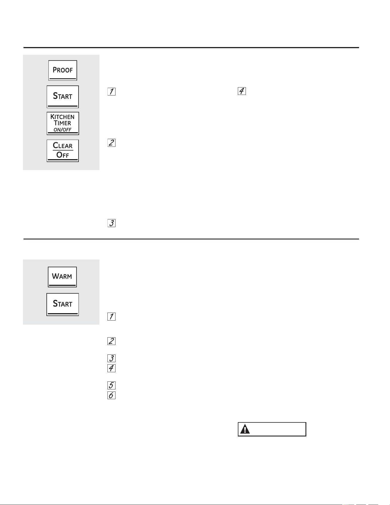
8VLQJWKHSURRILQJDQGZDUPLQJIHDWXUHV
+RZWR6HWWKH2YHQ)RU:DUPLQJ
7KH:$50IHDWXUHNHHSVFRRNHGIRRGVKRW
7KLVIHDWXUHLVQRWGHVLJQHGWRUHKHDWFROGIRRG
7RXVHWKH:$50IHDWXUHWRXFKWKH:$50
SDGDQGWKHQWKH67$57SDG
7RXVHWKH:$50IHDWXUHDIWHU7LPHG%DNLQJ
RU5RDVWLQJIROORZWKHVHVWHSV
7RXFKWKHPRGHRIFRRNLQJWKDW\RXZDQW
WRXVH%$.(&219(&7,21%$.(08/7,
5$&.RU&219(&7,2152$67
7RXFKWKHQXPEHUSDGVWRVHWWKHRYHQ
WHPSHUDWXUH
7RXFKWKH&22.,1*7,0(SDG
7RXFKWKHQXPEHUSDGVWRVHWWKHGHVLUHG
OHQJWKRIFRRNLQJWLPH
7RXFKWKH:$50SDG
7RXFKWKH67$57SDG
7R&ULVS6WDOH,WHPV
3ODFHIRRGLQORZVLGHGGLVKHVRUSDQV
)RUEHVWUHVXOWVSODFHWKHIRRGLWHPVLQD
VLQJOHOD\HU'RQRWVWDFN
/HDYHWKHPXQFRYHUHG
&KHFNFULVSQHVVDIWHU²PLQXWHV$GG
WLPHDVQHHGHG
,03257$17127(6
)RRGVKRXOGEHNHSWKRWLQLWVFRRNLQJ
FRQWDLQHURUWUDQVIHUUHGWRDKHDWVDIH
VHUYLQJGLVK
)RUPRLVWIRRGVFRYHUWKHPZLWKDQ
RYHQVDIHOLGRUDOXPLQXPIRLO
)ULHGRUFULVSIRRGVGRQRWQHHGWREH
FRYHUHGEXWFDQEHFRPHWRRGU\LIZDUPHG
IRUWRRORQJ
5HSHDWHGRSHQLQJRIWKHGRRUDOORZVWKHKRW
DLUWRHVFDSHDQGWKHIRRGWRFRRO
$OORZH[WUDWLPHIRUWKHWHPSHUDWXUHLQVLGH
WKHRYHQWRVWDELOL]HDIWHUDGGLQJLWHPV
:LWKODUJHORDGVLWPD\EHQHFHVVDU\WR
FRYHUVRPHRIWKHFRRNHGIRRGLWHPV
5HPRYHVHUYLQJVSRRQVHWFEHIRUHSODFLQJ
FRQWDLQHUVLQWKHRYHQ
'RQRWXVHSODVWLFFRQWDLQHUVOLGVRUSODVWLF
ZUDS
3ODVWLFFRQWDLQHUVOLGVRUSODVWLFZUDSZLOOPHOW
LISODFHGLQWKHRYHQ0HOWHGSODVWLFPD\QRW
EHUHPRYDEOHDQGLVQRWFRYHUHGXQGHU\RXU
ZDUUDQW\
7KHSURRILQJIHDWXUHPDLQWDLQVDZDUPHQYLURQPHQWXVHIXOIRUULVLQJ\HDVWOHDYHQHG
SURGXFWV
+RZWR6HWWKH2YHQ)RU3URRILQJRQVRPHPRGHOV
3ODFHWKHFRYHUHGGRXJKLQDGLVKLQWKH
RYHQRQUDFN%RU&
127()RUEHVWUHVXOWVFRYHUWKHGRXJKZLWKD
FORWKRUZLWKJUHDVHGSODVWLFZUDSWKHSODVWLF
PD\QHHGWREHDQFKRUHGXQGHUQHDWKWKH
FRQWDLQHUVRWKHRYHQIDQZLOOQRWEORZLWRII
7RXFKWKH3522) SDGDQGWKHQWKH
67$57SDG
7KHGLVSOD\ZLOOUHDG3U) SURRI
7KHRYHQLQWHULRUOLJKWWXUQVRQDQGUHPDLQVRQ
GXULQJSURRILQJ
7KHSURRILQJIHDWXUHDXWRPDWLFDOO\SURYLGHVWKH
RSWLPXPWHPSHUDWXUHIRUWKHSURRILQJSURFHVV
DQGWKHUHIRUHGRHVQRWKDYHDWHPSHUDWXUH
DGMXVWPHQW
6HWWKH.,7&+(17,0(5212))IRUWKH
PLQLPXPSURRIWLPH
:KHQSURRILQJLVILQLVKHGWRXFKWKH
&/($52))SDG
7RDYRLGORZHULQJWKHRYHQWHPSHUDWXUHDQG
OHQJWKHQLQJSURRILQJWLPHGRQRWRSHQWKH
RYHQGRRUXQQHFHVVDULO\
&KHFNEUHDGSURGXFWVHDUO\WRDYRLG
RYHUSURRILQJ
127(6
'RQRWXVHWKHSURRILQJPRGHIRUZDUPLQJ
IRRGRUNHHSLQJIRRGKRW7KHSURRILQJRYHQ
WHPSHUDWXUHLVQRWKRWHQRXJKWRKROGIRRGV
DWVDIHWHPSHUDWXUHV8VHWKH:$50IHDWXUH
WRNHHSIRRGZDUP
3URRILQJZLOOQRWRSHUDWHZKHQRYHQLVDERYH
)´+27µZLOOVKRZLQWKHGLVSOD\
&$87,21
6SHFLDOIHDWXUHVRI\RXURYHQFRQWURO *($SSOLDQFHVFRP
)DKUHQKHLWRU&HOVLXV7HPSHUDWXUH6HOHFWLRQ
<RXURYHQFRQWUROLVVHWWRXVHWKH)DKUHQKHLW
WHPSHUDWXUHVHOHFWLRQVEXW\RXPD\FKDQJHWKLV
WRXVHWKH&HOVLXVVHOHFWLRQV
7RXFKWKH%52,/+,/2DQG%$.( SDGVDW
WKHVDPHWLPHXQWLOWKHGLVSOD\VKRZV6)
7RXFKWKH&22.,1*7,0(DQG%52,/+,/2
SDGVDWWKHVDPHWLPH7KHGLVSOD\ZLOOVKRZ
) )DKUHQKHLW
7RXFKWKH&22.,1*7,0(DQG%52,/+,/2
SDGVDJDLQDWWKHVDPHWLPH7KHGLVSOD\ZLOO
VKRZ&&HOVLXV
7RXFKWKH67$57SDG
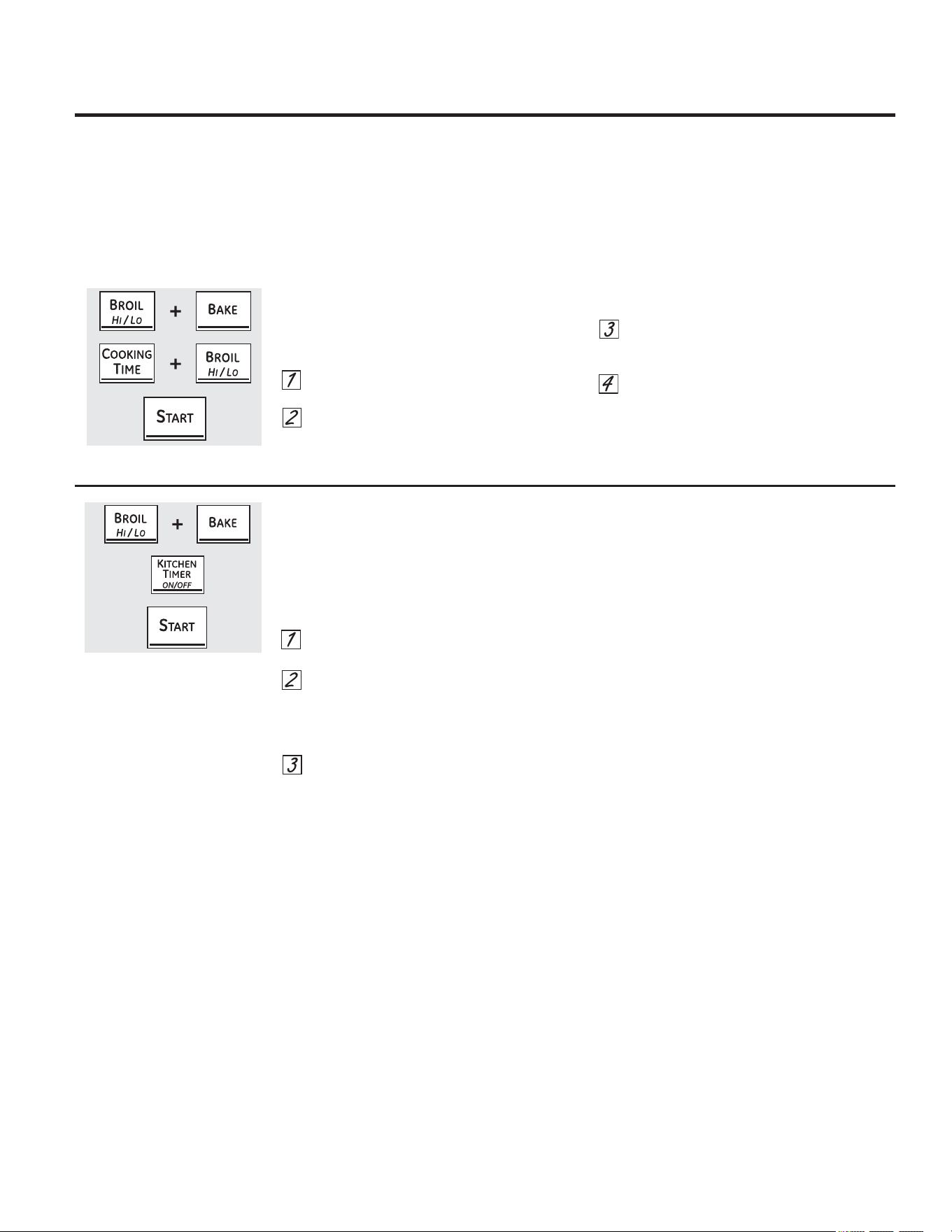
7RQHVDWWKH(QGRID7LPHG&\FOH
$WWKHHQGRIDWLPHGF\FOHVKRUWEHHSVZLOO
VRXQGIROORZHGE\RQHEHHSHYHU\VHFRQGV
XQWLOWKH&/($52))SDGLVWRXFKHG7KLV
FRQWLQXDOVHFRQGEHHSPD\EHFDQFHOOHG
7RFDQFHOWKHVHFRQGEHHS
7RXFKWKH%52,/+,/2DQG%$.(SDGVDW
WKHVDPHWLPHXQWLOWKHGLVSOD\VKRZV6)
7RXFKWKH.,7&+(17,0(5212))SDG
7KHGLVSOD\VKRZV&21%((3FRQWLQXRXV
EHHS7RXFKWKH.,7&+(17,0(5212))
SDGDJDLQ7KHGLVSOD\VKRZV%((37KLV
FDQFHOVWKHRQHEHHSHYHU\VHFRQGV
7RXFKWKH67$57SDG
<RXUQHZWRXFKSDGFRQWUROKDVDGGLWLRQDOIHDWXUHVWKDW\RXPD\FKRRVHWRXVH7KHIROORZLQJDUHWKHIHDWXUHVDQGKRZ
\RXPD\DFWLYDWHWKHP
7KHVSHFLDOIHDWXUHPRGHVFDQRQO\EHDFWLYDWHGZKLOHWKHGLVSOD\LVVKRZLQJWKHWLPHRIGD\7KH\UHPDLQLQWKHFRQWURO·V
PHPRU\XQWLOWKHVWHSVDUHUHSHDWHG
7RHQWHUDVSHFLDOIHDWXUHIRUHLWKHURYHQ\RXPXVWILUVWWRXFKWKH%52,/+,/2DQG%$.(SDGVDWWKHVDPHWLPH
:KHQWKHGLVSOD\VKRZV\RXUFKRLFHWRXFKWKH67$57SDG7KHVSHFLDOIHDWXUHVZLOOUHPDLQLQPHPRU\DIWHUDSRZHU
IDLOXUHH[FHSWIRUWKH6DEEDWKIHDWXUHZKLFKZLOOKDYHWREHUHVHW
6SHFLDOIHDWXUHVRI\RXURYHQFRQWURO
$XWR5HFLSH
&RQYHUVLRQRQVRPHPRGHOV
:KHQXVLQJFRQYHFWLRQEDNHWKH$XWR5HFLSH
&RQYHUVLRQIHDWXUHFDQDXWRPDWLFDOO\FRQYHUW
HQWHUHGUHJXODUEDNLQJWHPSHUDWXUHVWR
FRQYHFWLRQEDNLQJWHPSHUDWXUHV7KHGLVSOD\
ZLOOVKRZWKHFRQYHUWHGUHGXFHGWHPSHUDWXUH
)RUH[DPSOHLI\RXHQWHUDUHJXODUUHFLSH
WHPSHUDWXUHRIÛ)DQGWRXFKWKH67$57
SDGWKHGLVSOD\ZLOOVKRZ&21DQGWKH
FRQYHUWHGWHPSHUDWXUHRIÛ)
7RDFWLYDWHRUGHDFWLYDWHWKHIHDWXUH
7RXFKWKH%$.(DQG%52,/+,/2SDGVDW
WKHVDPHWLPHXQWLOWKHGLVSOD\VKRZV6)
7RXFKWKH&219(&7,21%$.(SDGXQWLO
WKHGLVSOD\VKRZV&2121&RQYHUVLRQ
2QRU&212))&RQYHUVLRQ2IIDV
GHVLUHG
7RXFKWKH67$57SDG
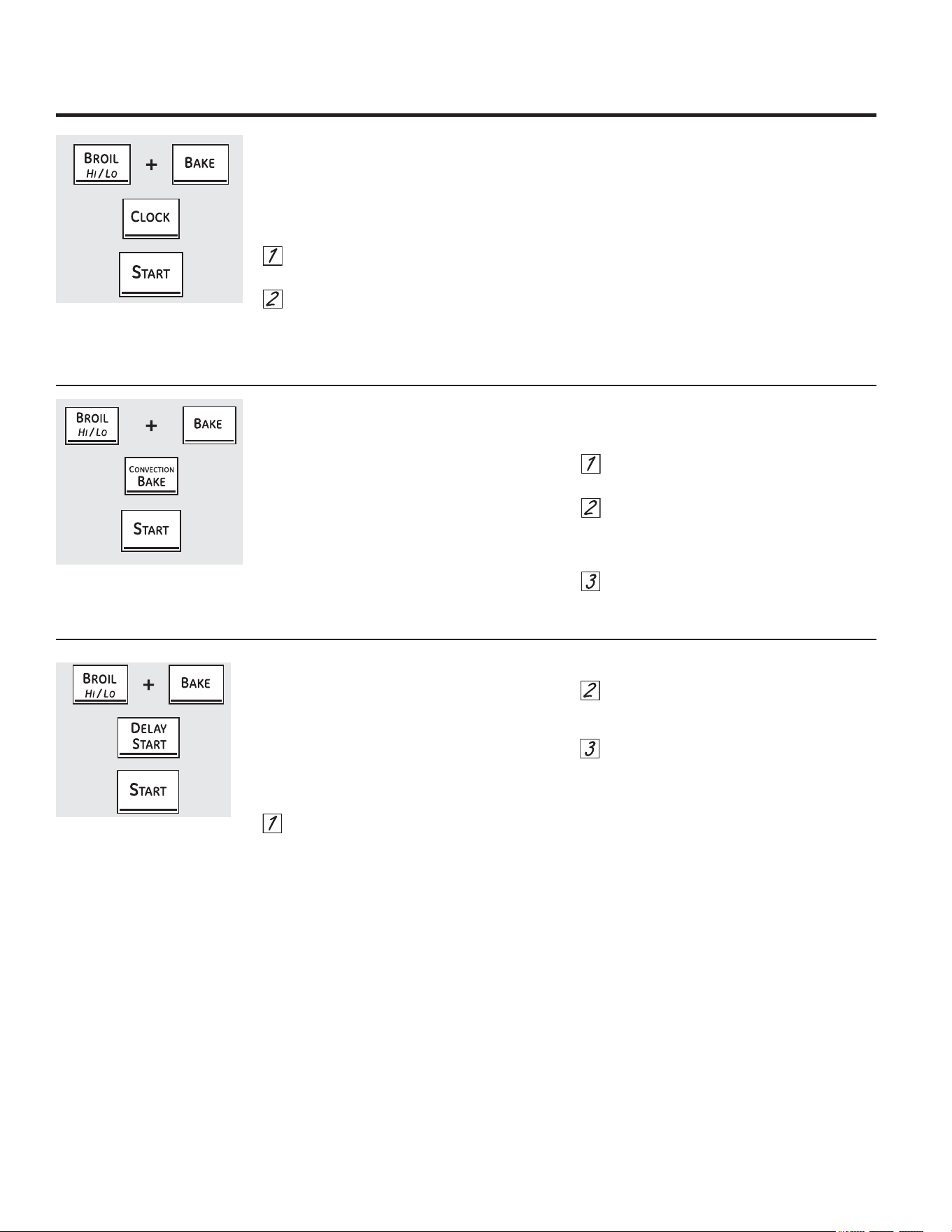
+RXU+RXURU&ORFN%ODFNRXW
<RXUFRQWUROLVVHWWRXVHDKRXUFORFN
,I\RXZRXOGSUHIHUWRKDYHDKRXUPLOLWDU\
WLPHFORFNRUEODFNRXWWKHFORFNGLVSOD\IROORZ
WKHVWHSVEHORZ
7RXFKWKH%52,/+,/2DQG%$.(SDGVDW
WKHVDPHWLPHXQWLOWKHGLVSOD\VKRZV6)
7RXFKWKH&/2&.SDGRQFH7KHGLVSOD\
ZLOOVKRZKU ,IWKLVLVWKHFKRLFH\RX
ZDQWWRXFKWKH67$57SDG
7RXFKWKH&/2&. SDGDJDLQWRFKDQJHWRWKH
KRXUPLOLWDU\WLPHFORFN7KHGLVSOD\ZLOO
VKRZKU,IWKLVLVWKHFKRLFH\RXZDQWWRXFK
WKH67$57 SDG
7RXFKWKH&/2&. SDGDJDLQWREODFNRXWWKH
FORFNGLVSOD\7KHGLVSOD\ZLOOVKRZ2)) ,IWKLVLV
WKHFKRLFH\RXZDQWWRXFKWKH67$57SDG
127(,IWKHFORFNLVLQWKHEODFNRXWPRGH\RX
ZLOOQRWEHDEOHWRXVHWKH'HOD\6WDUWIXQFWLRQ
+RXU6KXWGRZQ
:LWKWKLVIHDWXUHVKRXOG\RXIRUJHW
DQGOHDYHWKHRYHQRQWKHFRQWUROZLOO
DXWRPDWLFDOO\WXUQRIIWKHRYHQDIWHU
KRXUVGXULQJEDNLQJIXQFWLRQVRUDIWHU
KRXUVGXULQJDEURLOIXQFWLRQ
,I\RXZLVKWRWXUQ2)) WKLVIHDWXUHIROORZ
WKHVWHSVEHORZ
7RXFKWKH%52,/+,/2DQG%$.(SDGV
DWWKHVDPHWLPHXQWLOWKHGLVSOD\
VKRZV6)
7RXFKWKH'(/$<67$57SDGXQWLOQR
VKGQQRVKXWRIIDSSHDUVLQWKH
GLVSOD\
7RXFKWKH67$57SDGWRDFWLYDWHWKHQR
VKXWRIIDQGOHDYHWKHFRQWUROVHWLQWKLV
VSHFLDOIHDWXUHVPRGH
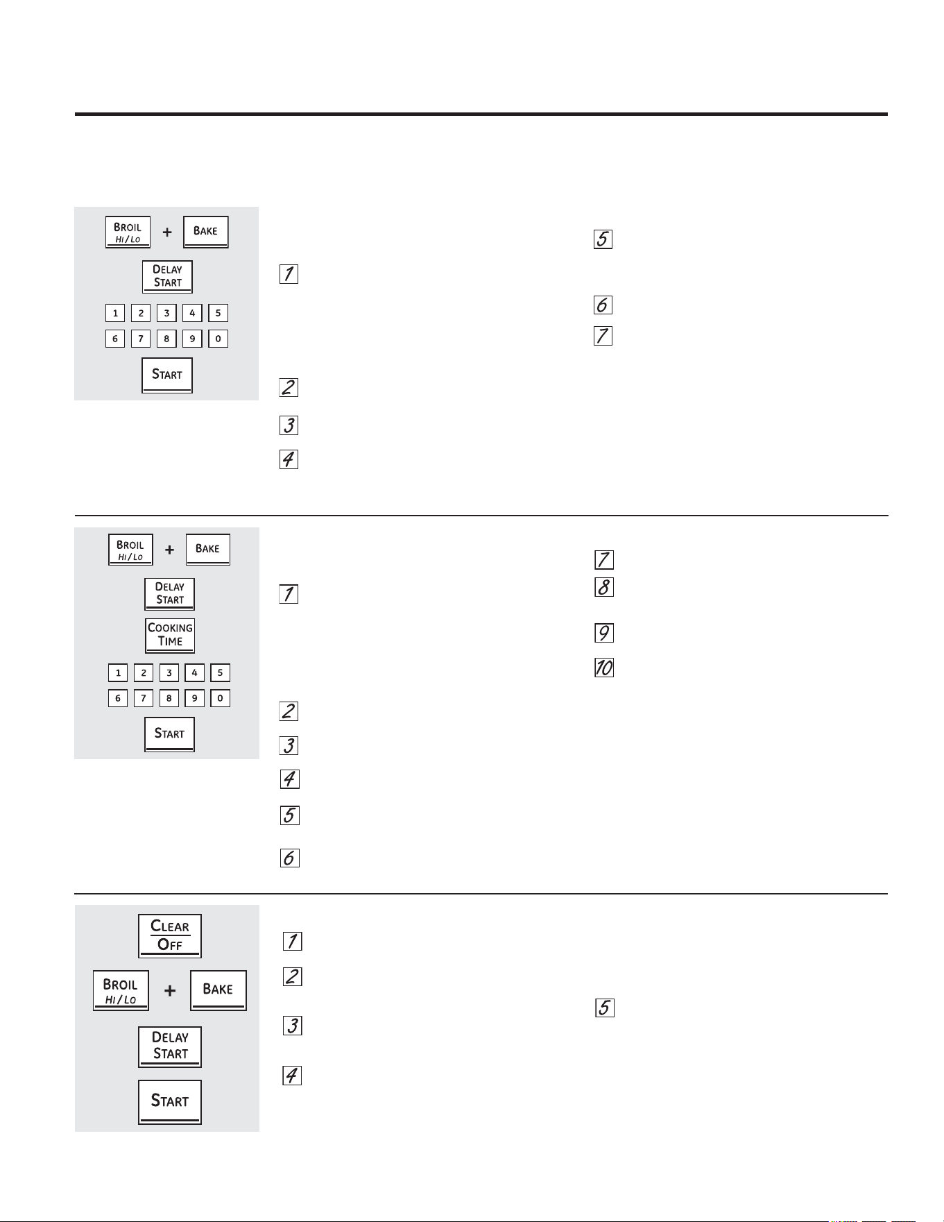
8VLQJWKH6DEEDWKIHDWXUH
'HVLJQHGIRUXVHRQWKH-HZLVK6DEEDWKDQG+ROLGD\VRQVRPHPRGHOV
*($SSOLDQFHVFRP
7RXFKWKH&/($52))SDG
,IWKHRYHQLVFRRNLQJZDLWIRUDUDQGRPGHOD\
SHULRGRIDSSUR[LPDWHO\VHFRQGVWR
PLQXWHXQWLORQO\LVLQWKHGLVSOD\
7RXFKDQGKROGERWKWKH%52,/+,/2DQG
%$.(SDGVDWWKHVDPHWLPHXQWLOWKHGLVSOD\
VKRZV6)
7DSWKH'(/$<67$57SDGXQWLOVKGQRUQR
VKGQDSSHDUVLQWKHGLVSOD\
&KRRVHVKGQLQGLFDWLQJWKDWWKHRYHQZLOO
DXWRPDWLFDOO\WXUQRIIDIWHUKRXUVRUQR
VKGQLQGLFDWLQJWKDWWKHRYHQZLOOQRW
DXWRPDWLFDOO\WXUQRIIDIWHUKRXUV
3UHVV67$57ZKHQWKHRSWLRQWKDW\RXZDQWLV
LQWKHGLVSOD\VKGQRUQRVKGQ
127(,IDSRZHURXWDJHRFFXUUHGZKLOHWKHRYHQ
ZDVLQ6DEEDWKWKHRYHQZLOODXWRPDWLFDOO\WXUQRII
DQGVWD\RIIHYHQZKHQWKHSRZHUUHWXUQV7KHRYHQ
FRQWUROPXVWEHUHVHW6RPHPRGHOVZLOOUHVXPH
6DEEDWKPRGHKRZHYHURSHQLQJWKHGRRUZLOO
DFWLYDWHWKHRYHQOLJKW
7KH6DEEDWKIHDWXUHFDQEHXVHGIRUEDNLQJURDVWLQJRQO\,WFDQQRWEHXVHGIRUFRQYHFWLRQEURLOLQJVHOIFOHDQLQJRU'HOD\6WDUW
FRRNLQJ
127(7KHRYHQOLJKWFRPHVRQDXWRPDWLFDOO\RQVRPHPRGHOVZKHQWKHGRRULVRSHQHGDQGJRHVRIIZKHQWKHGRRULVFORVHG7KHEXOEPD\EHUHPRYHG6HH
WKH2YHQ/LJKW5HSODFHPHQWVHFWLRQ2QPRGHOVZLWKDOLJKWVZLWFKRQWKHFRQWUROSDQHOWKHRYHQOLJKWPD\EHWXUQHGRQDQGOHIWRQ
+RZWR6HWIRU5HJXODU%DNLQJ5RDVWLQJ
0DNHVXUHWKHFORFNVKRZVWKHFRUUHFWWLPHRIGD\
DQGWKHRYHQLVRII
7RXFKDQGKROGERWKWKH%52,/+,/2DQG
%$.(SDGVDWWKHVDPHWLPHXQWLOWKHGLVSOD\
VKRZV6)
127(,IEDNHRUEURLODSSHDUVLQWKHGLVSOD\WKH
%52,/+,/2DQG%$.(SDGVZHUHQRWWRXFKHG
DWWKHVDPHWLPH7RXFKWKH&/($52))SDG
DQGEHJLQDJDLQ
7DSWKH'(/$<67$57SDGXQWLO6$EE$W+
DSSHDUVLQWKHGLVSOD\
7RXFKWKH67$57 SDGDQGZLOODSSHDULQWKH
GLVSOD\7KHRYHQLVQRZLQ6DEEDWKPRGH
7RXFKWKH%$.( SDG1RVLJQDOZLOOEHJLYHQ
8VLQJWKHQXPEHUSDGVHQWHUWKHGHVLUHG
WHPSHUDWXUHEHWZHHQ)DQG)1R
VLJQDORUWHPSHUDWXUHZLOOEHJLYHQ7KHUHLVQR
GHIDXOWWHPSHUDWXUH
7RXFKWKH67$57 SDG
$IWHUDUDQGRPGHOD\SHULRGRIDSSUR[LPDWHO\
VHFRQGVWRPLQXWHZLOODSSHDULQWKH
GLVSOD\LQGLFDWLQJ WKDWWKHRYHQLVEDNLQJ
URDVWLQJ,IGRHVQ·WDSSHDULQWKHGLVSOD\
VWDUWDJDLQDW6WHS
7RDGMXVWWKHRYHQWHPSHUDWXUHWRXFKWKH%$.(SDG
HQWHUWKHQHZWHPSHUDWXUHXVLQJWKHQXPEHUSDGV
DQGWRXFKWKH67$57SDG
127(7KH&/($52))DQG&22.,1*7,0(SDGV
DUHDFWLYHGXULQJWKH6DEEDWKIHDWXUH
+RZWR([LWWKH6DEEDWK)HDWXUH
:KHQWKHGLVSOD\VKRZVWKH
RYHQLVVHWLQ6DEEDWK:KHQWKH
GLVSOD\VKRZVWKHRYHQLV
EDNLQJURDVWLQJ
:KHQWKHGLVSOD\VKRZVWKH
RYHQLVVHWLQ6DEEDWK:KHQWKH
GLVSOD\VKRZV
WKHRYHQLV
EDNLQJURDVWLQJ
+RZWR6HWIRU7LPHG%DNLQJ5RDVWLQJ³,PPHGLDWH6WDUWDQG$XWRPDWLF6WRS
0DNHVXUHWKHFORFNVKRZVWKHFRUUHFWWLPHRIGD\
DQGWKHRYHQLVRII
7RXFKDQGKROGERWKWKH%52,/+,/2DQG
%$.(SDGVDWWKHVDPHWLPHXQWLOWKHGLVSOD\
VKRZV6)
127(,IEDNHRUEURLODSSHDUVLQWKHGLVSOD\WKH
%52,/+,/2DQG%$.(SDGVZHUHQRWWRXFKHG
DWWKHVDPHWLPH7RXFKWKH&/($52))SDG
DQGEHJLQDJDLQ
7DSWKH'(/$<67$57SDGXQWLO6$EE$W+
DSSHDUVLQWKHGLVSOD\
7RXFKWKH67$57 SDGDQGZLOODSSHDULQWKH
GLVSOD\7KHRYHQLVQRZLQ6DEEDWKPRGH
7RXFKWKH&22.,1*7,0(SDG1RVLJQDOZLOO
EHJLYHQ
7RXFKWKHQXPEHUSDGVWRVHWWKHGHVLUHG
OHQJWKRIFRRNLQJWLPHEHWZHHQPLQXWHDQG
KRXUVDQGPLQXWHV
7RXFKWKH67$57 SDG
7RXFKWKH%$.(SDG1RVLJQDOZLOOEHJLYHQ
8VLQJWKHQXPEHUSDGVHQWHUWKHGHVLUHG
WHPSHUDWXUH1RVLJQDORUWHPSHUDWXUHZLOOEH
JLYHQ7KHUHLVQRGHIDXOWWHPSHUDWXUH
7RXFKWKH67$57 SDG
$IWHUDUDQGRPGHOD\SHULRGRIDSSUR[LPDWHO\
VHFRQGVWRPLQXWHZLOODSSHDULQWKH
GLVSOD\LQGLFDWLQJWKDWWKHRYHQLV
EDNLQJ
URDVWLQJ
,IGRHVQ·WDSSHDULQWKHGLVSOD\
VWDUWDJDLQDW6WHS
7RDGMXVWWKHRYHQWHPSHUDWXUHWRXFKWKH%$.(SDG
HQWHUWKHQHZWHPSHUDWXUHXVLQJWKHQXPEHUSDGV
DQGWRXFKWKH67$57SDG
:KHQFRRNLQJLVILQLVKHGWKHGLVSOD\ZLOOFKDQJH
IURPWRDQGZLOODSSHDULQGLFDWLQJWKDW
WKHRYHQKDVWXUQHG2))EXWLVVWLOOVHWLQ6DEEDWK
5HPRYHWKHFRRNHGIRRG

'RQRWXVHDVWHHOZRROSDGLWZLOOVFUDWFKWKH
VXUIDFH
7RFOHDQWKHVWDLQOHVVVWHHOVXUIDFHXVHZDUP
VXGV\ZDWHURUDVWDLQOHVVVWHHOFOHDQHURU
SROLVK$OZD\VZLSHWKHVXUIDFHLQWKHGLUHFWLRQ
RIWKHJUDLQ)ROORZWKHFOHDQHULQVWUXFWLRQVIRU
FOHDQLQJWKHVWDLQOHVVVWHHOVXUIDFH
7RLQTXLUHDERXWSXUFKDVLQJVWDLQOHVVVWHHO
DSSOLDQFHFOHDQHURUSROLVKRUWRILQGWKH
ORFDWLRQRIDGHDOHUQHDUHVW\RXSOHDVH
FDOORXUWROOIUHHQXPEHU
1DWLRQDO3DUWV&HQWHU
*($SSOLDQFHVFRP
6WDLQOHVV6WHHO6XUIDFHVRQVRPHPRGHOV
%HVXUHDOOFRQWUROVDUHRIIDQGDOOVXUIDFHVDUHFRROEHIRUHFOHDQLQJDQ\SDUWRIWKHUDQJH
&RQWURO3DQHO
,IGHVLUHGWKHWRXFKSDGVPD\EHGHDFWLYDWHGEHIRUH
FOHDQLQJ
6HH+RZWR/RFN2XWWKH&RQWUROVLQWKH8VLQJWKH
FORFNNLWFKHQWLPHUDQGFRQWUROORFNRXWVHFWLRQLQWKLV
PDQXDO
&OHDQXSVSODWWHUVZLWKDGDPSFORWK
<RXPD\DOVRXVHDJODVVFOHDQHU
5HPRYHKHDYLHUVRLOZLWKZDUPVRDS\ZDWHU'RQRW
XVHDEUDVLYHVRIDQ\NLQG
5HDFWLYDWHWKHWRXFKSDGVDIWHUFOHDQLQJ
3DLQWHG6XUIDFHV
3DLQWHGVXUIDFHVLQFOXGHWKHVLGHVRIWKHUDQJHDQG
WKHGRRUWRSRIFRQWUROSDQHODQGWKHGUDZHUIURQW
&OHDQWKHVHZLWKVRDSDQGZDWHURUDYLQHJDUDQG
ZDWHUVROXWLRQ
'RQRWXVHFRPPHUFLDORYHQFOHDQHUVFOHDQLQJ
SRZGHUVVWHHOZRRORUKDUVKDEUDVLYHVRQDQ\
SDLQWHGVXUIDFH
+RZWR5HPRYH3URWHFWLYH6KLSSLQJ)LOPDQG3DFNDJLQJ7DSH
&DUHIXOO\JUDVSDFRUQHURIWKHSURWHFWLYHVKLSSLQJ
ILOPZLWK\RXUILQJHUVDQGVORZO\SHHOLWIURPWKH
DSSOLDQFHVXUIDFH'RQRWXVHDQ\VKDUSLWHPVWR
UHPRYHWKHILOP5HPRYHDOORIWKHILOPEHIRUHXVLQJ
WKHDSSOLDQFHIRUWKHILUVWWLPH
7RHQVXUHQRGDPDJHLVGRQHWRWKHILQLVKRIWKH
SURGXFWWKHVDIHVWZD\WRUHPRYHWKHDGKHVLYHIURP
SDFNDJLQJWDSHRQQHZDSSOLDQFHVLVDQDSSOLFDWLRQ
RIDKRXVHKROGOLTXLGGLVKZDVKLQJGHWHUJHQW$SSO\
ZLWKDVRIWFORWKDQGDOORZWRVRDN
127(7KHDGKHVLYHPXVWEHUHPRYHGIURPDOOSDUWV
,WFDQQRWEHUHPRYHGLILWLVEDNHGRQ
&RQWURO.QREV
7KHFRQWURONQREVPD\EHUHPRYHGIRUHDVLHU
FOHDQLQJ0DNHVXUHWKHNQREVDUHLQWKH2))
SRVLWLRQVDQGSXOOWKHPVWUDLJKWRIIWKHVWHPVIRU
FOHDQLQJ
7KHNQREVFDQEHFOHDQHGLQDGLVKZDVKHURUWKH\
PD\DOVREHZDVKHGZLWKVRDSDQGZDWHU0DNH
VXUHWKHLQVLGHRIWKHNQREVDUHGU\EHIRUHUHSODFLQJ
5HSODFHWKHNQREVLQWKH2)) SRVLWLRQWRHQVXUH
SURSHUSODFHPHQW
3RUFHODLQ(QDPHO&RRNWRSRQVRPHPRGHOV
7KHSRUFHODLQHQDPHOILQLVKLVVWXUG\EXW
EUHDNDEOHLIPLVXVHG7KLVILQLVKLVDFLG
UHVLVWDQW+RZHYHUDQ\DFLGLFIRRGVVSLOOHG
VXFKDVIUXLWMXLFHVWRPDWRRUYLQHJDUVKRXOG
QRWEHSHUPLWWHGWRUHPDLQRQWKHILQLVK
,IDFLGVVSLOORQWKHFRRNWRSZKLOHLWLVKRWXVH
DGU\SDSHUWRZHORUFORWKWRZLSHLWXSULJKW
DZD\:KHQWKHVXUIDFHKDVFRROHGZDVKZLWK
VRDSDQGZDWHU5LQVHZHOO
)RURWKHUVSLOOVVXFKDVIDWVSDWWHULQJVZDVK
ZLWKVRDSDQGZDWHURUFOHDQVLQJSRZGHUV
DIWHUWKHVXUIDFHKDVFRROHG5LQVHZHOO3ROLVK
ZLWKDGU\FORWK
&DUHDQGFOHDQLQJRIWKHUDQJH
,I\RXUUDQJHLVUHPRYHGIRUFOHDQLQJVHUYLFLQJRUDQ\UHDVRQEH
VXUHWKHDQWLWLSGHYLFHLVUHHQJDJHGSURSHUO\ZKHQWKHUDQJHLV
UHSODFHG)DLOXUHWRWDNHWKLVSUHFDXWLRQFRXOGUHVXOWLQWLSSLQJRI
WKHUDQJHDQGFDQUHVXOWLQGHDWKRUVHULRXVEXUQVWRFKLOGUHQRU
DGXOWV
:$51,1*
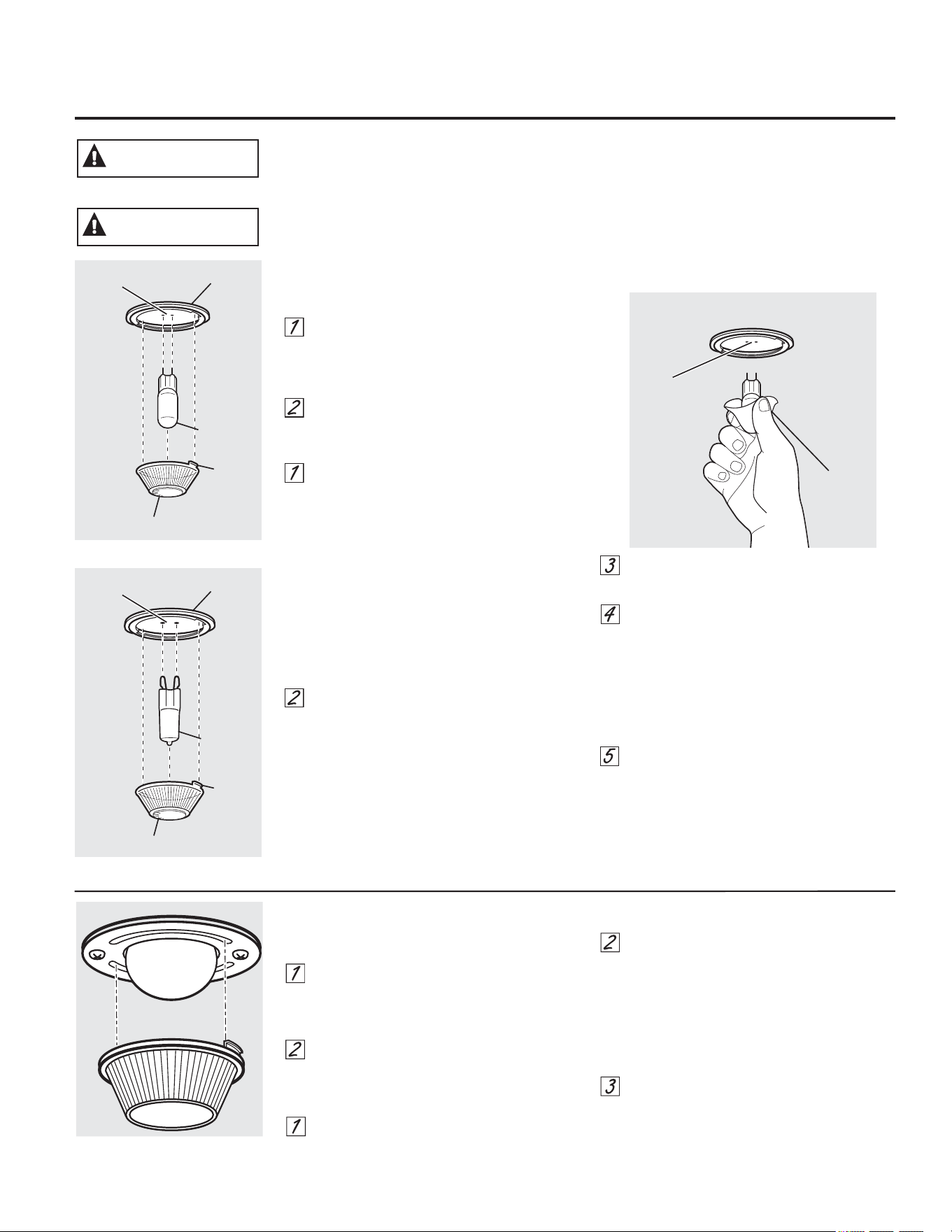
2YHQ/LJKW5HSODFHPHQWRQVRPHPRGHOV
7RUHPRYH
7XUQWKHJODVVFRYHUFRXQWHUFORFNZLVH
WXUQXQWLOWKHWDEVRIWKHJODVVFRYHUFOHDU
WKHJURRYHVRIWKHVRFNHW:HDULQJODWH[
JORYHVPD\RIIHUDEHWWHUJULS
8VLQJJORYHVRUDGU\FORWKUHPRYHWKH
EXOEE\SXOOLQJLWVWUDLJKWRXW
7RUHSODFH
8VHDQHZYROWKDORJHQEXOEQRW
WRH[FHHGZDWWV5HSODFHWKHEXOEZLWK
WKHVDPHW\SHRIEXOEWKDWZDVUHPRYHG
<RXUPRGHOZLOOKDYHRQHRIWKHWZRW\SHV
VKRZQRQWKHOHIW7RGHWHUPLQHWKH
FRUUHFWUHSODFHPHQWEXOEFKHFNWKHEXOE
WHUPLQDOV%XOEVZLWKVWUDLJKWSLQ
WHUPLQDOVDUH*EXOEV%XOEVZLWK
ORRSHGWHUPLQDOVDUH*EXOEV'RQRW
LQWHUFKDQJH%HVXUHWKHUHSODFHPHQW
EXOELVUDWHGYROWVRUYROWV127
YROWV
8VLQJJORYHVRUDGU\FORWKUHPRYHWKH
EXOEIURPLWVSDFNDJLQJ'RQRWWRXFKWKH
EXOEZLWKEDUHILQJHUV2LOIURPVNLQZLOO
GDPDJHWKHEXOEDQGVKRUWHQLWVOLIH
3XVKWKHEXOEVWUDLJKWLQWRWKHUHFHSWDFOH
DOOWKHZD\
3ODFHWKHWDEVRIWKHJODVVFRYHULQWRWKH
JURRYHVRIWKHVRFNHW7XUQWKHJODVVFRYHU
FORFNZLVHWXUQ
)RULPSURYHGOLJKWLQJLQVLGHWKHRYHQ
FOHDQWKHJODVVFRYHUIUHTXHQWO\XVLQJD
ZHWFORWK7KLVVKRXOGEHGRQHZKHQWKH
RYHQLVFRPSOHWHO\FRRO
5HFRQQHFWHOHFWULFDOSRZHUWRWKHRYHQ
*%XOE
6RFNHW
7DE
*ODVVFRYHU
5HFHSWDFOH
8VH
JORYHVRU
FORWK
5HFHSWDFOH
*%XOE
6RFNHW
7DE
*ODVVFRYHU
5HFHSWDFOH
RQVRPHPRGHOV
RQVRPHPRGHOV
6+2&.25%851+$=$5'%HIRUHUHSODFLQJRYHQOLJKWEXOEGLVFRQQHFW
WKHHOHFWULFDOSRZHUWRWKHUDQJHDWWKHPDLQIXVHRUFLUFXLWEUHDNHUSDQHO
)DLOXUHWRGRVRPD\UHVXOWLQHOHFWULFVKRFNRUEXUQ
:$51,1*
%851+$=$5'7KHJODVVFRYHUDQGEXOEVKRXOGEHUHPRYHGZKHQFRRO
7RXFKLQJKRWJODVVZLWKEDUHKDQGVRUDGDPSFORWKFDQFDXVHEXUQV
&$87,21
*($SSOLDQFHVFRP
2YHQ/LJKW5HSODFHPHQW
RQVRPHPRGHOV
7RUHPRYH
7XUQWKHJODVVFRYHUFRXQWHUFORFNZLVH
WXUQXQWLOWKHWDEVRIWKHJODVVFRYHUFOHDU
WKHJURRYHVRIWKHVRFNHW:HDULQJODWH[
JORYHVPD\RIIHUDEHWWHUJULS
5HPRYHWKHEXOEE\WXUQLQJLWFRXQWHU
FORFNZLVH
7RUHSODFH
5HSODFHEXOEZLWKDQHZZDWW
DSSOLDQFHEXOE,QVHUWWKHEXOEDQGWXUQLW
FORFNZLVHXQWLOLWLVWLJKW
3ODFHWKHWDEVRIWKHJODVVFRYHULQWRWKH
JURRYHVRIWKHVRFNHW7XUQWKHJODVV
FRYHUFORFNZLVHWXUQ
)RULPSURYHGOLJKWLQJLQVLGHWKHRYHQFOHDQWKH
JODVVFRYHUIUHTXHQWO\XVLQJDZHWFORWK7KLV
VKRXOGEHGRQHZKHQWKHRYHQLVFRPSOHWHO\
FRRO
5HFRQQHFWHOHFWULFDOSRZHUWRWKHRYHQ
7KHGRRULVYHU\KHDY\%HFDUHIXOZKHQUHPRYLQJ
DQGOLIWLQJWKHGRRU
'RQRWOLIWWKHGRRUE\WKHKDQGOH
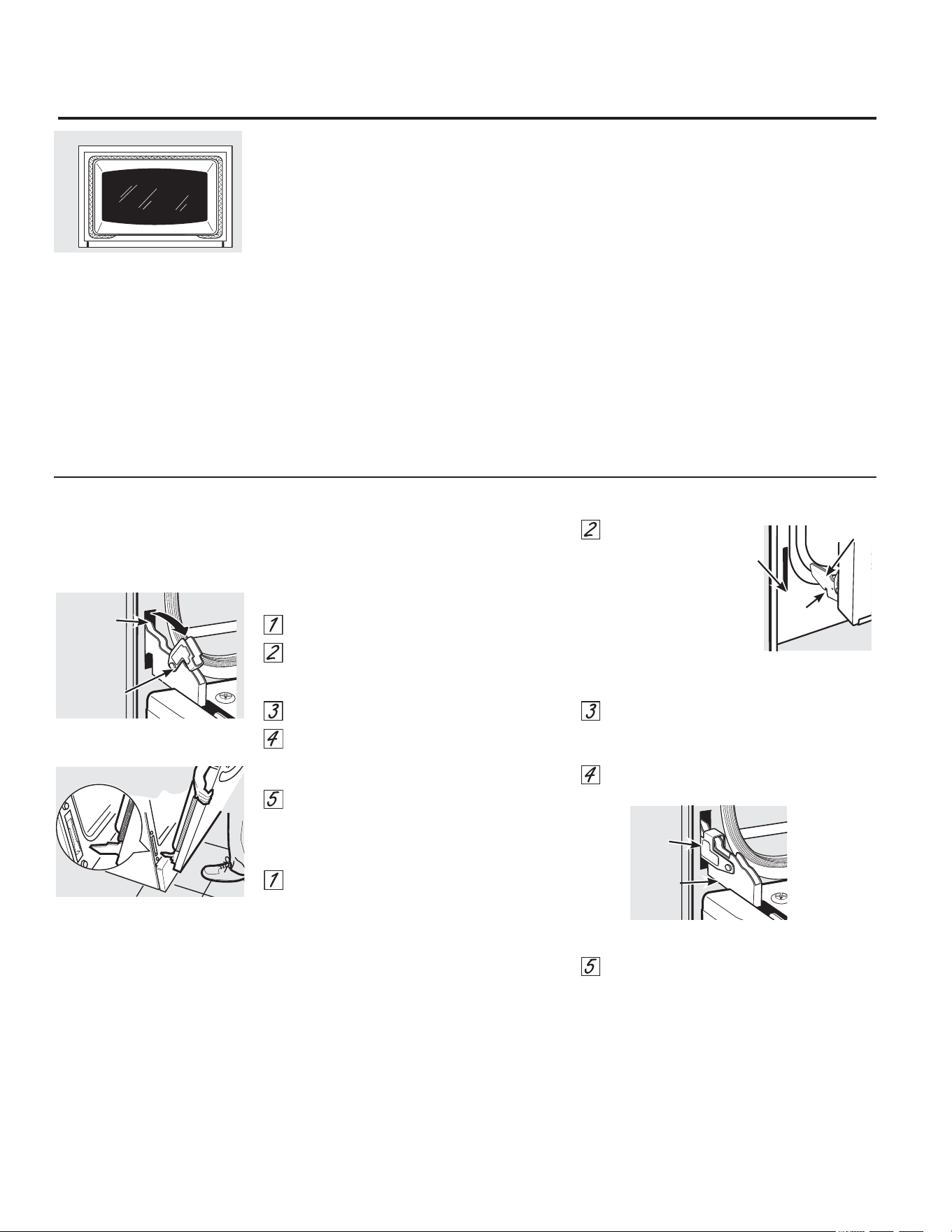
7RUHPRYHWKHGRRU
)XOO\RSHQWKHGRRU
3XOOWKHKLQJHORFNVGRZQWRZDUGWKHGRRU
IUDPHWRWKHXQORFNHGSRVLWLRQ$WRROVXFKDV
DVPDOOIODWEODGHVFUHZGULYHUPD\EHUHTXLUHG
)LUPO\JUDVSERWKVLGHVRIWKHGRRUDWWKHWRS
&ORVHGRRUWRWKHGRRUUHPRYDOSRVLWLRQZKLFK
LVKDOIZD\EHWZHHQWKHEURLOVWRSSRVLWLRQDQG
IXOO\FORVHG
/LIWGRRUXSDQGRXWXQWLOWKHKLQJHDUPLVFOHDU
RIWKHVORW
7RUHSODFHWKHGRRU
)LUPO\JUDVSERWKVLGHVRIWKHGRRUDWWKHWRS
:LWKWKH
GRRUDWWKHVDPH
DQJOH
DVWKHUHPRYDO
SRVLWLRQVHDWWKH
LQGHQWDWLRQRIWKHKLQJH
DUPLQWRWKHERWWRPHGJH
RIWKHKLQJHVORW7KHQRWFK
LQWKHKLQJHDUPPXVWEHIXOO\VHDWHGLQWRWKH
ERWWRPRIWKHVORW
)XOO\RSHQWKHGRRU,IWKHGRRUZLOOQRWIXOO\
RSHQWKHLQGHQWDWLRQLVQRWVHDWHGFRUUHFWO\LQ
WKHERWWRPHGJHRIWKHVORW
3XVKWKHKLQJHORFNVXSDJDLQVWWKHIURQWIUDPH
RIWKHRYHQFDYLW\WRWKHORFNHGSRVLWLRQ
&ORVHWKHRYHQGRRU
/LIW2II2YHQ'RRURQVRPHPRGHOV
7KHJDVNHWLVGHVLJQHGZLWKDJDS
DWWKHERWWRPWRDOORZIRUSURSHUDLU
FLUFXODWLRQ
'RQRWUXERUFOHDQWKHGRRUJDVNHW³LW
KDVDQH[WUHPHO\ORZUHVLVWDQFHWR
DEUDVLRQ
,I\RXQRWLFHWKHJDVNHWEHFRPLQJ
ZRUQIUD\HGRUGDPDJHGLQDQ\ZD\
RULILWKDVEHFRPHGLVSODFHGRQWKH
GRRU\RXVKRXOGKDYHLWUHSODFHG
7RFOHDQWKHLQVLGHRIWKHGRRU
%HFDXVHWKHDUHDLQVLGHWKHJDVNHWLVFOHDQHG
GXULQJWKHVHOIFOHDQF\FOH\RXGRQRWQHHGWR
FOHDQWKLVE\KDQG
7KHDUHDRXWVLGHWKHJDVNHWDQGWKHGRRUOLQHU
FDQEHFOHDQHGZLWKDVRDSILOOHGRUSODVWLF
VFRXULQJSDGKRWZDWHUDQGGHWHUJHQW5LQVHZHOO
ZLWKDYLQHJDUDQGZDWHUVROXWLRQ
7RFOHDQWKHRXWVLGHRIWKHGRRU
8VHVRDSDQGZDWHUWRWKRURXJKO\FOHDQWKHWRS
VLGHVDQGIURQWRIWKHRYHQGRRU5LQVHZHOO<RX
PD\DOVRXVHDJODVVFOHDQHUWRFOHDQWKHJODVVRQ
WKHRXWVLGHRIWKHGRRU'RQRWOHWZDWHUGULSLQWR
WKHYHQWRSHQLQJV
,IDQ\VWDLQRQWKHGRRUYHQWWULPLVSHUVLVWHQWXVH
DVRIWDEUDVLYHFOHDQHU
DQGDVSRQJHVFUXEEHUIRUEHVWUHVXOWV
6SLOODJHRIPDULQDGHVIUXLWMXLFHVWRPDWRVDXFHV
DQGEDVWLQJPDWHULDOVFRQWDLQLQJDFLGVPD\
FDXVHGLVFRORUDWLRQDQGVKRXOGEHZLSHGXS
LPPHGLDWHO\:KHQVXUIDFHLVFRROFOHDQDQG
ULQVH
'RQRWXVHRYHQFOHDQHUVFOHDQLQJSRZGHUVRU
KDUVKDEUDVLYHVRQWKHRXWVLGHRIWKHGRRU
&OHDQLQJWKH2YHQ'RRU
5HPRYDOSRVLWLRQ
+LQJH
ORFN
3XOOKLQJHORFNVGRZQWRXQORFN
,QGHQWDWLRQ
%RWWRP
HGJH
RIVORW
+LQJHDUP
6ORW
+LQJH
ORFN
3XVKKLQJHORFNVXSWRORFN
+LQJH
DUP
&DUHDQGFOHDQLQJRIWKHUDQJH
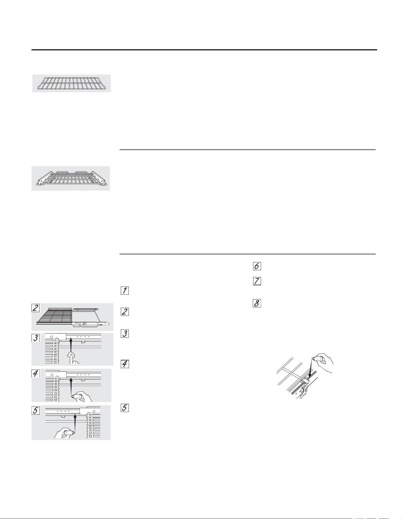
2YHQ5DFNV
$OORYHQUDFNVPD\EHFOHDQHGE\KDQGZLWKDQ
DEUDVLYHFOHDQHURUVWHHOZRRO$IWHUFOHDQLQJ
ULQVHWKHUDFNVZLWKFOHDQZDWHUDQGGU\ZLWKD
FOHDQFORWK*UD\SRUFHODLQFRDWHGRYHQUDFNV
PD\UHPDLQLQWKHRYHQGXULQJWKHVHOIFOHDQLQJ
F\FOHZLWKRXWEHLQJGDPDJHG7KHQLFNHOSODWHG
RYHQUDFNVPD\UHPDLQLQWKHRYHQGXULQJWKH
VHOIFOHDQLQJF\FOHEXWWKH\ZLOOORVHWKHLUOXVWHU
DQGEHFRPHKDUGWRVOLGH,WZLOOEHQHFHVVDU\
WRJUHDVHDOORYHQUDFNVLGHHGJHVZLWKDOLJKW
FRDWLQJRIYHJHWDEOHRLODIWHUFOHDQLQJWKHPE\
KDQGRULQWKHRYHQ7KLVZLOOKHOSPDLQWDLQWKH
HDVHRIVOLGLQJWKHUDFNVLQDQGRXWRIWKHRYHQ
([WHQVLRQUDFNVPD\EHFOHDQHGE\KDQG
ZLWKDQDEUDVLYHFOHDQHURUVWHHOZRRO'XULQJ
FOHDQLQJEHFDUHIXOQRWWRDOORZZDWHURU
FOHDQHUWRHQWHUWKHH[WHQVLRQVOLGHVRQWKH
VLGHVRIWKHUDFN
127('RQRWFOHDQLQDGLVKZDVKHU
,IWKHUDFNEHFRPHVKDUGWRUHPRYHRUUHSODFH
OLJKWO\ZLSHWKHRYHQUDFNVXSSRUWVZLWK
FRRNLQJRLO'RQRWZLSHFRRNLQJRLORQWKH
VOLGHV
,IWKHUDFNEHFRPHVGLIILFXOWWRVOLGHRULIWKH
SDGGOHLVGLIILFXOWWRDFWXDWHWKHUDFNPD\
QHHGWREHOXEULFDWHGXVLQJWKH*UDSKLWH
/XEULFDWLRQVKLSSHGZLWK\RXURYHQ7RRUGHU
DGGLWLRQDO*UDSKLWH/XEULFDWLRQFDOORXU
1DWLRQDO3DUWV&HQWHUDWDQG
UHIHUHQFH:%7
([WHQVLRQ5DFNRQVRPHPRGHOV
7ROXEULFDWHWKHVOLGHV
127('RQRWVSUD\H[WHQVLRQUDFNZLWKFRRNLQJ
VSUD\RURWKHUOXEULFDQWVSUD\V
5HPRYHWKHUDFNIURPWKHRYHQ6HH
([WHQVLRQ5DFNLQWKH8VLQJWKHRYHQ
VHFWLRQ
)XOO\H[WHQGWKHUDFNRQDWDEOHRU
FRXQWHUWRS1HZVSDSHUPD\EHSODFHG
XQGHUQHDWKWKHUDFNIRUHDV\FOHDQXS
,IWKHUHLVGHEULVLQWKHVOLGHWUDFNVZLSHLW
DZD\XVLQJDSDSHUWRZHO
127($Q\JUDSKLWHOXEULFDQWZLSHGDZD\
PXVWEHUHSODFHGVHHVWHSVWKURXJK
6KDNHWKHJUDSKLWHOXEULFDQWEHIRUH
RSHQLQJLW6WDUWLQJZLWKWKHOHIWVOLGH
PHFKDQLVPRIWKHUDFNSODFHIRXU
VPDOOGURSVRIOXEULFDQWRQWKHWZR
ERWWRPWUDFNVRIWKHVOLGHFORVHWRWKH
EHDULQJFDUULHUV
5HSHDWIRUWKHULJKWVOLGHPHFKDQLVPRI
WKHUDFN
2SHQDQGFORVHWKHUDFNVHYHUDOWLPHVWR
GLVWULEXWHWKHOXEULFDQW
5HSODFHWKHFDSRQWKHOXEULFDQWDQG
VKDNHLWDJDLQ7XUQWKHUDFNRYHUDQG
UHSHDWVWHSVDQG
&ORVHWKHUDFNWXUQUDFNULJKWVLGHXSDQG
SODFHLQWKHRYHQ6HH([WHQVLRQ5DFNLQ
WKH8VLQJWKHRYHQVHFWLRQ
7ROXEULFDWHWKHSDGGOH
6KDNHOXEULFDQWDQGDSSO\WRWKHPRYLQJSDUWV
RIWKHSDGGOHPHFKDQLVPVDVVKRZQ
*($SSOLDQFHVFRP
$OORZWKHFRRNWRSWRFRRO
8VHDVLQJOHHGJHUD]RUEODGHVFUDSHU
DWDSSUR[LPDWHO\DDQJOHDJDLQVW
WKHJODVVVXUIDFHDQGVFUDSHWKHVRLO,W
ZLOOEHQHFHVVDU\WRDSSO\SUHVVXUHWR
WKHUD]RUVFUDSHULQRUGHUWRUHPRYH
WKHUHVLGXH
$IWHUVFUDSLQJZLWKWKHUD]RUVFUDSHU
VSUHDGDIHZGURSVRI&(5$0$%5<7(
&HUDPLF&RRNWRS&OHDQHURQWKHHQWLUH
EXUQHGUHVLGXHDUHD8VHWKH&(5$0$
%5<7(
&OHDQLQJ3DGWRUHPRYHDQ\
UHPDLQLQJUHVLGXH
)RUDGGLWLRQDOSURWHFWLRQDIWHUDOO
UHVLGXHKDVEHHQUHPRYHGSROLVKWKH
HQWLUHVXUIDFHZLWK&(5$0$%5<7(
&HUDPLF&RRNWRS&OHDQHUDQGDSDSHU
WRZHO
%XUQHG2Q5HVLGXH
127('$0$*(WR\RXUJODVVVXUIDFHPD\
RFFXULI\RXXVHVFUXESDGVRWKHUWKDQWKRVH
UHFRPPHQGHG
$OORZWKHFRRNWRSWRFRRO
6SUHDGDIHZGURSVRI&(5$0$%5<7(
&HUDPLF&RRNWRS&OHDQHURQWKHHQWLUH
EXUQHGUHVLGXHDUHD
8VLQJWKHLQFOXGHG&(5$0$%5<7(
&OHDQLQJ3DGIRU&HUDPLF&RRNWRSVUXE
WKHUHVLGXHDUHDDSSO\LQJSUHVVXUHDV
QHHGHG
,IDQ\UHVLGXHUHPDLQVUHSHDW
WKHVWHSVOLVWHGDERYHDVQHHGHG
)RUDGGLWLRQDOSURWHFWLRQDIWHUDOO
UHVLGXHKDVEHHQUHPRYHGSROLVKWKH
HQWLUHVXUIDFHZLWK&(5$0$%5<7(
&HUDPLF&RRNWRS&OHDQHUDQGDSDSHU
WRZHO
7KH&(5$0$%5<7(
&HUDPLF
&RRNWRS6FUDSHUDQGDOO
UHFRPPHQGHGVXSSOLHVDUH
DYDLODEOHWKURXJKRXU3DUWV
&HQWHU6HHLQVWUXFWLRQVXQGHU´7R
2UGHU3DUWVµVHFWLRQRQQH[WSDJH
127('RQRWXVHDGXOORU
QLFNHGEODGH
+HDY\%XUQHG2Q5HVLGXH
8VHD&(5$0$%5<7(
&OHDQLQJ
3DGIRU&HUDPLF&RRNWRSV
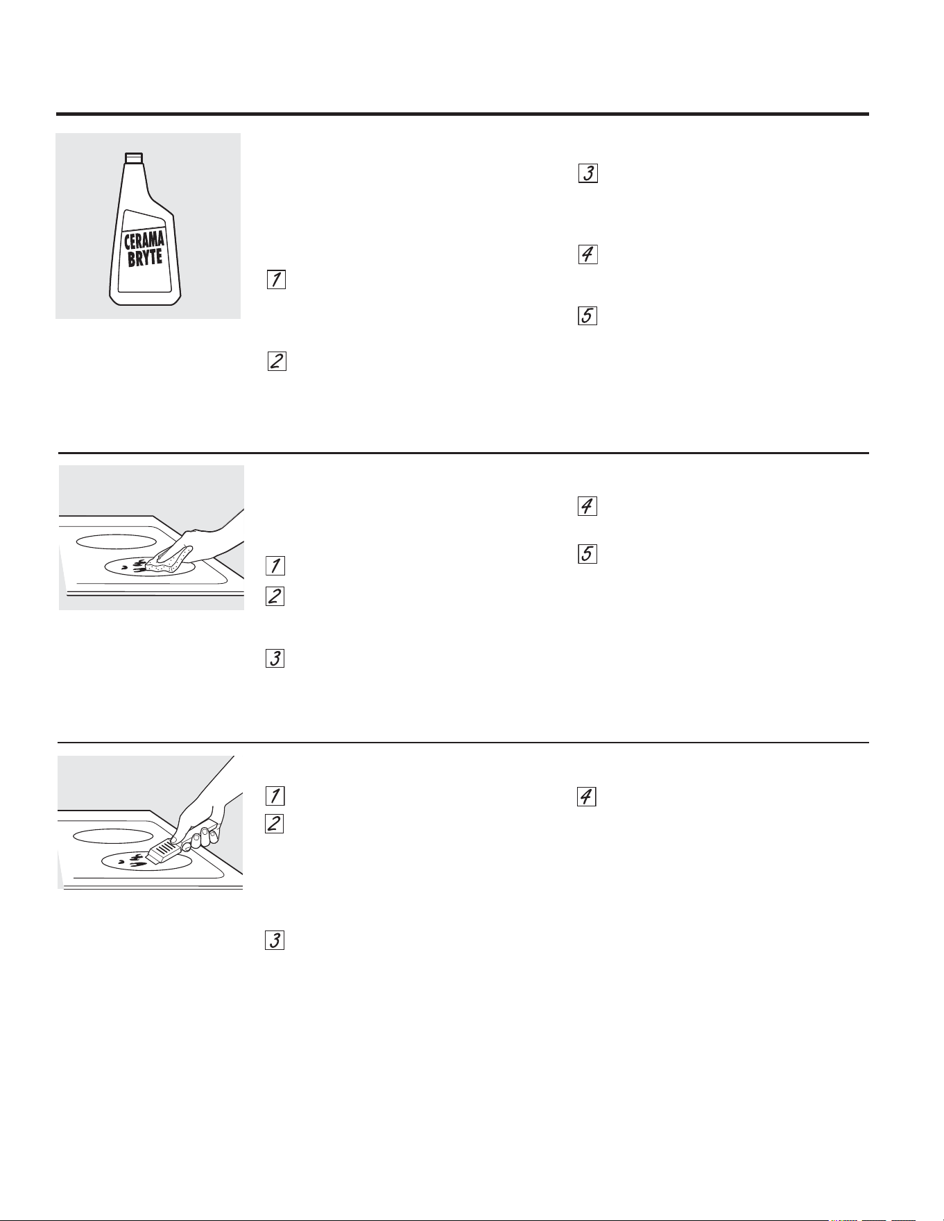
1RUPDO'DLO\8VH&OHDQLQJ
21/<XVH&(5$0$%5<7(
&HUDPLF&RRNWRS
&OHDQHURQWKHJODVVFRRNWRS2WKHUFUHDPV
PD\QRWEHDVHIIHFWLYH
7RPDLQWDLQDQGSURWHFWWKHVXUIDFHRI\RXU
JODVVFRRNWRSIROORZWKHVHVWHSV
%HIRUHXVLQJWKHFRRNWRSIRUWKH
ILUVWWLPHFOHDQLWZLWK&(5$0$%5<7(
&HUDPLF&RRNWRS&OHDQHU7KLVKHOSV
SURWHFWWKHWRSDQGPDNHVFOHDQXSHDVLHU
'DLO\XVHRI&(5$0$%5<7(
&HUDPLF
&RRNWRS&OHDQHUZLOOKHOSNHHSWKH
FRRNWRSORRNLQJQHZ
6KDNHWKHFOHDQLQJFUHDPZHOO$SSO\D
IHZGURSVRI&(5$0$%5<7(
&HUDPLF
&RRNWRS&OHDQHUGLUHFWO\
WRWKHFRRNWRS
8VHDSDSHUWRZHORU&(5$0$%5<7(
&OHDQLQJ3DGIRU&HUDPLF&RRNWRSVWR
FOHDQWKHHQWLUHFRRNWRSVXUIDFH
8VHDGU\FORWKRUSDSHUWRZHO
WRUHPRYHDOOFOHDQLQJUHVLGXH
1RQHHGWRULQVH
127(,WLVYHU\LPSRUWDQWWKDW\RX'2127
KHDWWKHFRRNWRSXQWLOLWKDVEHHQFOHDQHG
WKRURXJKO\
&OHDQ\RXUFRRNWRSDIWHUHDFK
VSLOO8VH&(5$0$%5<7(
&HUDPLF
&RRNWRS&OHDQHU
&OHDQLQJWKHJODVVFRRNWRS
RQVRPHPRGHOV
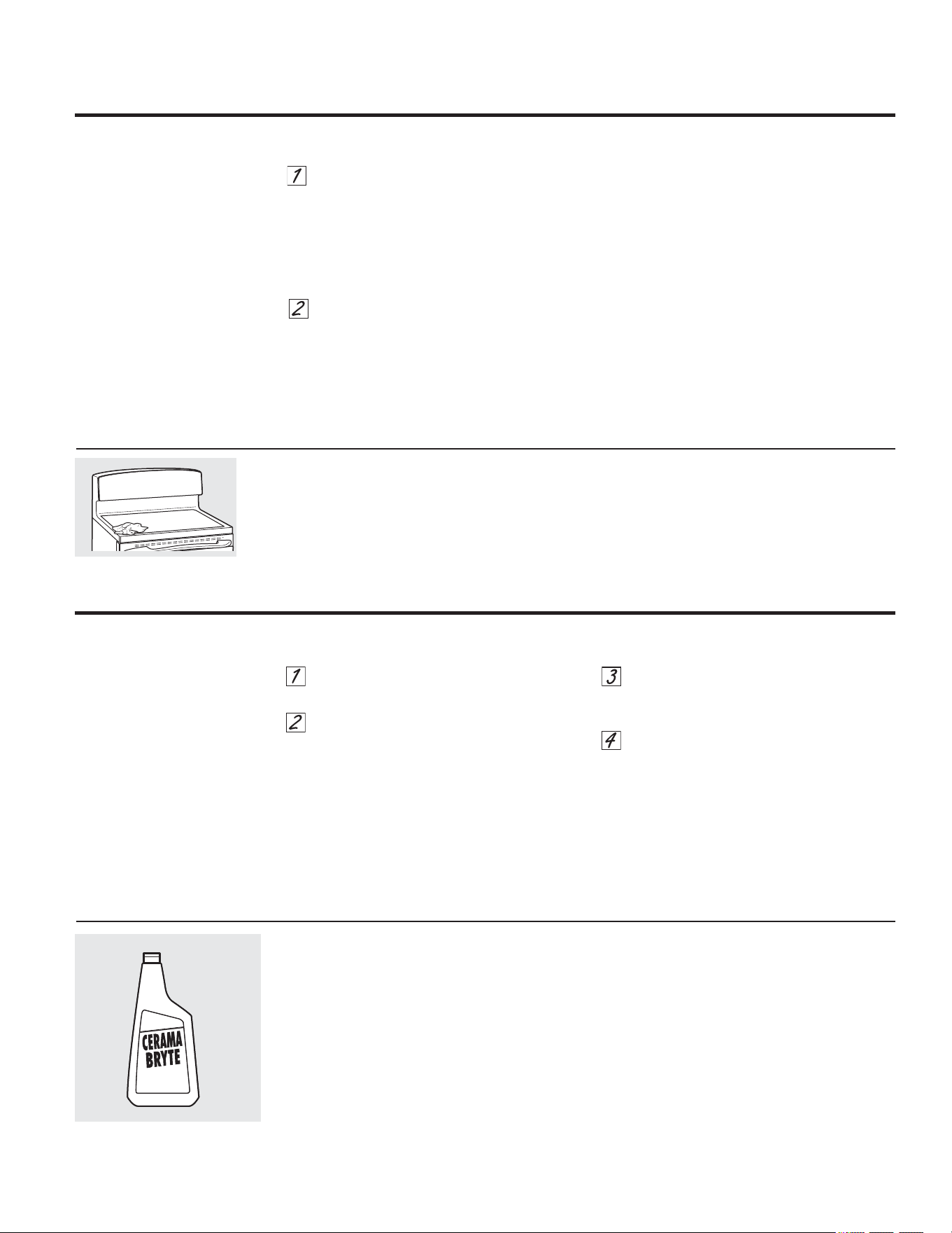
7RRUGHU&(5$0$%5<7(
&HUDPLF&RRNWRS
&OHDQHUDQGWKHFRRNWRSVFUDSHUSOHDVHFDOO
RXUWROOIUHHQXPEHU
1DWLRQDO3DUWV&HQWHU
&(5$0$%5<7(
&HUDPLF
&RRNWRS&OHDQHU:;;
&(5$0$%5<7(
&HUDPLF
&RRNWRS6FUDSHU
:;;
.LW:%;
.LWLQFOXGHVFUHDPDQGFRRNWRSVFUDSHU
&(5$0$%5<7(
&OHDQLQJ3DGVIRU
&HUDPLF&RRNWRSV :;;
7XUQRIIDOOVXUIDFHXQLWV5HPRYHKRW
SDQV
:HDULQJDQRYHQPLWW
D8VHDVLQJOHHGJHUD]RU
EODGHVFUDSHU&(5$0$%5<7(
&HUDPLF&RRNWRS6FUDSHU
WRPRYHWKHVSLOOWRDFRRO
DUHDRQWKHFRRNWRS
E5HPRYHWKHVSLOOZLWKSDSHUWRZHOV
$Q\UHPDLQLQJVSLOORYHUVKRXOGEHOHIW
XQWLOWKHVXUIDFHRIWKHFRRNWRSKDV
FRROHG
'RQ·WXVHWKHVXUIDFHXQLWVDJDLQXQWLO
DOORIWKHUHVLGXHKDVEHHQFRPSOHWHO\
UHPRYHG
127(,ISLWWLQJRULQGHQWDWLRQLQWKHJODVV
VXUIDFHKDVDOUHDG\RFFXUUHGWKHFRRNWRS
JODVVZLOOKDYHWREHUHSODFHG
,QWKLVFDVHVHUYLFHZLOOEHQHFHVVDU\
'DPDJHIURP6XJDU\6SLOOVDQG0HOWHG3ODVWLF
6XJDU\VSLOORYHUVVXFKDV
MHOOLHVIXGJHFDQG\V\UXSV
RUPHOWHGSODVWLFVFDQFDXVH
SLWWLQJRIWKHVXUIDFHRI\RXU
FRRNWRSQRWFRYHUHGE\WKH
ZDUUDQW\XQOHVVWKHVSLOOLV
UHPRYHGZKLOHVWLOOKRW6SHFLDO
FDUHVKRXOGEHWDNHQZKHQ
UHPRYLQJKRWVXEVWDQFHV
%HVXUHWRXVHDQHZVKDUS
UD]RUVFUDSHU
'RQRWXVHDGXOORUQLFNHG
EODGH
%HFDUHIXOQRWWRVOLGHSRWVDQGSDQV
DFURVV\RXUFRRNWRS,WZLOOOHDYHPHWDO
PDUNLQJVRQWKHFRRNWRSVXUIDFH
7KHVHPDUNVDUHUHPRYDEOHXVLQJWKH
&(5$0$%5<7(
&HUDPLF&RRNWRS&OHDQHU
ZLWKWKH&(5$0$%5<7(
&OHDQLQJ3DG
IRU&HUDPLF&RRNWRSV
,ISRWVZLWKDWKLQRYHUOD\RIDOXPLQXP
RUFRSSHUDUHDOORZHGWRERLOGU\WKH
RYHUOD\PD\OHDYHEODFNGLVFRORUDWLRQ
RQWKHFRRNWRS
7KLVVKRXOGEHUHPRYHGLPPHGLDWHO\
EHIRUHKHDWLQJDJDLQRUWKH
GLVFRORUDWLRQPD\EHSHUPDQHQW
127(&DUHIXOO\FKHFNWKHERWWRPRISDQVIRU
URXJKQHVVWKDWZRXOGVFUDWFKWKHFRRNWRS
0HWDO0DUNVDQG6FUDWFKHV
7R2UGHU3DUWV
*ODVVVXUIDFH³SRWHQWLDOIRUSHUPDQHQWGDPDJH
7RFOHDQWKHFRRNWRSVHDODURXQGWKHHGJHV
RIWKHJODVVOD\DZHWFORWKRQLWIRUDIHZ
PLQXWHVWKHQZLSHFOHDQZLWKQRQDEUDVLYH
FOHDQHUV
&RRNWRS6HDO
*($SSOLDQFHVFRP
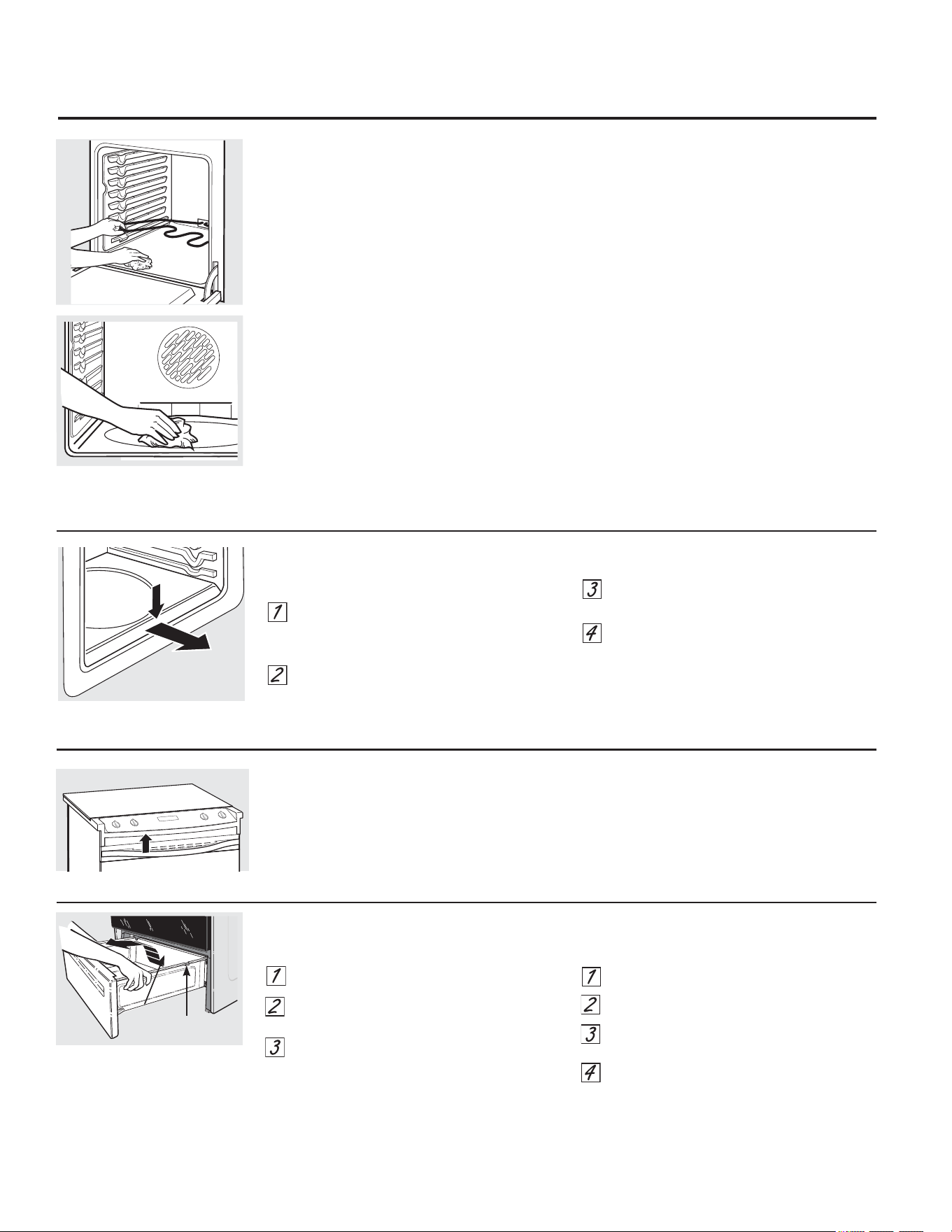
2YHQ+HDWLQJ(OHPHQWV
'RQRWFOHDQWKHEDNHHOHPHQWRUWKHEURLO
HOHPHQW$Q\VRLOZLOOEXUQRIIZKHQWKH
HOHPHQWVDUHKHDWHG
7RFOHDQWKHRYHQIORRUJHQWO\OLIWWKHEDNH
HOHPHQW2QVRPHPRGHOVWKHEDNHHOHPHQWLV
QRWH[SRVHGDQGLVXQGHUWKHRYHQIORRU&OHDQ
ZLWKZDUPVRDS\ZDWHU
:LSHXSKHDY\VRLORQWKHRYHQ
ERWWRP
6WRUDJH'UDZHU5HPRYDO
7RUHPRYHWKHGUDZHU
3XOOWKHGUDZHURXWXQWLOLWVWRSV
/LIWWKHIURQWRIWKHGUDZHUXQWLOWKHVWRSV
FOHDUWKHJXLGHV
5HPRYHWKHGUDZHU
7RUHSODFHWKHGUDZHU
3ODFHWKHGUDZHUUDLOVRQWKHJXLGHV
3XVKWKHGUDZHUEDFNXQWLOLWVWRSV
/LIWWKHIURQWRIWKHGUDZHUDQGSXVKEDFN
XQWLOWKHVWRSVFOHDUWKHJXLGHV
/RZHUWKHIURQWRIWKHGUDZHUDQGSXVK
EDFNXQWLOLWFORVHV
6WRSJXLGH
5DLO
&DUHDQGFOHDQLQJRIWKHUDQJH
2YHQ9HQW
7KHRYHQYHQWLVDERYHWKHOHIWVLGHRIWKHGRRU
7KLVDUHDFRXOGEHFRPHKRWGXULQJRYHQXVH
,WLVQRUPDOIRUVWHDPWRFRPHRXWRI
WKHYHQW
7KHYHQWLVLPSRUWDQWIRUSURSHUDLUFLUFXODWLRQ
1HYHUEORFNWKLVYHQW
3UHVVGRZQDQGSXOORXW
5HPRYDEOH2YHQ)ORRURQVRPHPRGHOV
7RUHPRYHWKHRYHQIORRUIRUHDVLHUFOHDQLQJ
5HPRYHWKHRYHQGRRUXVLQJWKH
LQVWUXFWLRQVLQWKH/LIW2II2YHQ'RRU
VHFWLRQ
3UHVVGRZQDQGSXOORXWWKHUHPRYDEOH
RYHQIORRU
&OHDQWKHRYHQIORRUZLWKZDUPVRDS\
ZDWHU
:KHQUHLQVWDOOLQJWKHRYHQIORRUEHVXUH
WRVOLGHLWDOOWKHZD\WRWKHEDFNRIWKH
RYHQ
,03257$17 $OZD\VUHSODFHWKHUHPRYDEOH
IORRUEHIRUHWKHQH[WXVH

7URXEOHVKRRWLQJ7LSV
6DYHWLPHDQGPRQH\5HYLHZWKHFKDUWVRQWKHIROORZLQJ
SDJHVILUVWDQG\RXPD\QRWQHHGWRFDOOIRUVHUYLFH
3UREOHP 3RVVLEOH&DXVHV :KDW7R'R
6XUIDFHXQLWVZLOOQRW ,PSURSHUFRRNZDUH 8VHSDQVZKLFKDUHIODWDQGPDWFKWKHGLDPHWHURI
PDLQWDLQDUROOLQJERLO EHLQJXVHG WKHVXUIDFHXQLWVHOHFWHG
RUFRRNLQJLVQRW
,QVRPHDUHDVWKHSRZHU &RYHUSDQZLWKDOLGXQWLOGHVLUHGKHDWLVREWDLQHG
IDVWHQRXJK
YROWDJHPD\EHORZ
6XUIDFHXQLWVGR $IXVHLQ\RXUKRPHPD\EH 5HSODFHWKHIXVHRUUHVHWWKHFLUFXLWEUHDNHU
QRWZRUNSURSHUO\ EORZQRUWKHFLUFXLWEUHDNHU
WULSSHG
&RRNWRSFRQWUROV &KHFNWRVHHWKHFRUUHFWFRQWUROLVVHWIRUWKHVXUIDFH
LPSURSHUO\VHW XQLW\RXDUHXVLQJ
6XUIDFHXQLWVWRSV 7KLVLVQRUPDO7KHXQLW
JORZLQJZKHQWXUQHG LVVWLOORQDQGKRW
WRDORZHUVHWWLQJ
6FUDWFKHVPD\DSSHDU ,QFRUUHFWFOHDQLQJ 6FUDWFKHVDUHQRWUHPRYDEOH7LQ\VFUDWFKHVZLOOEHFRPH
DVFUDFNVRQFRRNWRS PHWKRGVEHLQJXVHG OHVVYLVLEOHLQWLPHDVDUHVXOWRIFOHDQLQJ
JODVVVXUIDFH
&RRNZDUHZLWKURXJKERWWRPV 7RDYRLGVFUDWFKHVXVHWKHUHFRPPHQGHGFOHDQLQJ
EHLQJXVHGRUFRDUVHSDUWLFOHV SURFHGXUHV0DNHVXUHERWWRPVRIFRRNZDUHDUHFOHDQ
VDOWRUVDQGZHUHEHWZHHQ EHIRUHXVHDQGXVHFRRNZDUHZLWKVPRRWKERWWRPV
WKHFRRNZDUHDQGWKHVXUIDFH
RIWKHFRRNWRS
&RRNZDUHKDVEHHQVOLG
DFURVVWKHFRRNWRSVXUIDFH
$UHDVRIGLVFRORUDWLRQ )RRGVSLOORYHUVQRWFOHDQHG 6HHWKH&OHDQLQJWKHJODVVFRRNWRSVHFWLRQ
RQWKHFRRNWRS EHIRUHQH[WXVH
+RWVXUIDFHRQDPRGHO 7KLVLVQRUPDO7KHVXUIDFHPD\DSSHDUGLVFRORUHG
ZLWKDOLJKWFRORUHGFRRNWRS ZKHQLWLVKRW7KLVLVWHPSRUDU\DQGZLOOGLVDSSHDU
DVWKHJODVVFRROV
3ODVWLFPHOWHGWR +RWFRRNWRSFDPHLQWR 6HHWKH*ODVVVXUIDFH³SRWHQWLDOIRUSHUPDQHQWGDPDJH
WKHVXUIDFH FRQWDFWZLWKSODVWLFSODFHG VHFWLRQLQWKH&OHDQLQJWKHJODVVFRRNWRSVHFWLRQ
RQWKHKRWFRRNWRS
3LWWLQJRULQGHQWDWLRQ +RWVXJDUPL[WXUHVSLOOHG &DOODTXDOLILHGWHFKQLFLDQIRUUHSODFHPHQW
RIWKHFRRNWRS RQWKHFRRNWRS
)UHTXHQWF\FOLQJ ,PSURSHUFRRNZDUH 8VHRQO\IODWFRRNZDUHWRPLQLPL]HF\FOLQJ
RIIDQGRQRI EHLQJXVHG
VXUIDFHXQLWV
2YHQOLJKWGRHV /LJKWEXOELVORRVH 7LJKWHQRUUHSODFHWKHEXOE
QRWZRUN
2YHQZLOOQRWZRUN 3OXJRQUDQJHLVQRWFRPSOHWHO\ 0DNHVXUHHOHFWULFDOSOXJLVSOXJJHGLQWRDOLYHSURSHUO\
LQVHUWHGLQWKHHOHFWULFDORXWOHW JURXQGHGRXWOHW
$IXVHLQ\RXUKRPHPD\ 5HSODFHWKHIXVHRUUHVHWWKHFLUFXLWEUHDNHU
EHEORZQRUWKHFLUFXLW
EUHDNHUWULSSHG
2YHQFRQWUROVLPSURSHUO\VHW 6HHWKH8VLQJWKHRYHQVHFWLRQ
2YHQWRRKRW $OORZWKHRYHQWRFRROWREHORZORFNLQJWHPSHUDWXUH
%HIRUH<RX&DOO)RU6HUYLFH« *($SSOLDQFHVFRP

3UREOHP 3RVVLEOH&DXVHV :KDW7R'R
)RRGGRHVQRWEDNH 2YHQFRQWUROVLPSURSHUO\VHW 6HHWKH8VLQJWKHRYHQ VHFWLRQ
RUURDVWSURSHUO\
5DFNSRVLWLRQLVLQFRUUHFW 6HHWKH8VLQJWKHRYHQVHFWLRQ
RUWKHUDFNLVQRWOHYHO
,QFRUUHFWFRRNZDUHRU 6HHWKH8VLQJWKHRYHQVHFWLRQ
FRRNZDUHRILPSURSHU
VL]HEHLQJXVHG
2YHQWKHUPRVWDWQHHGV 6HHWKH$GMXVWWKHRYHQWKHUPRVWDW³'RLW\RXUVHOI
DGMXVWPHQW VHFWLRQ
)RRGGRHVQRW 2YHQFRQWUROVLPSURSHUO\VHW 0DNHVXUH\RXWRXFKWKH%52,/+,/2SDG
EURLOSURSHUO\
,PSURSHUUDFNSRVLWLRQ 6HHWKH%URLOLQJ*XLGH
EHLQJXVHG
&RRNZDUHQRWVXLWHG )RUEHVWUHVXOWVXVHDSDQGHVLJQHGIRUEURLOLQJ
IRUEURLOLQJ
7KHSUREHLVSOXJJHG 8QSOXJDQGUHPRYHWKHSUREHIURPWKHRYHQ
LQWRWKHRXWOHWLQWKHRYHQ
RQVRPHPRGHOV
,QVRPHDUHDVWKHSRZHU 3UHKHDWWKHEURLOHOHPHQWIRUPLQXWHV
YROWDJHPD\EHORZ
%URLOIRUWKHORQJHVWSHULRGRIWLPHUHFRPPHQGHG
LQWKH%URLOLQJ*XLGH
2YHQWHPSHUDWXUH 2YHQWKHUPRVWDW 6HHWKH$GMXVWWKHRYHQWKHUPRVWDW³'RLW\RXUVHOI
WRRKRWRUWRRFROG QHHGVDGMXVWPHQW VHFWLRQ
6WRUDJHGUDZHU 5HDUGUDZHUVXSSRUWLV 5HSRVLWLRQWKHGUDZHU6HHWKH6WRUDJH'UDZHU
LVFURRNHG RQWRSRIWKHJXLGHUDLO5HPRYDOLQVWUXFWLRQVLQWKH&DUHDQGFOHDQLQJRIWKH
UDQJHVHFWLRQ
&KHFNWRPDNHVXUHGUDZHULVSURSHUO\VHDWHGLIUHPRYHG
6WRUDJHGUDZHU 3RZHUFRUGPD\EH 5HSRVLWLRQWKHGUDZHUDQGSRZHUFRUG6HHWKH
ZRQ·WFORVH REVWUXFWLQJGUDZHU6WRUDJH'UDZHU5HPRYDOLQVWUXFWLRQVLQWKH&DUHDQG
LQWKHORZHUEDFNFOHDQLQJRIWKHUDQJHVHFWLRQ
RIWKHUDQJH
5HDUGUDZHUVXSSRUWLV 5HSRVLWLRQWKHGUDZHU6HHWKH6WRUDJH'UDZHU
RQWRSRIWKHJXLGHUDLO5HPRYDOLQVWUXFWLRQVLQWKH&DUHDQGFOHDQLQJRIWKH
UDQJHVHFWLRQ
2YHQGRRULVFURRNHG 7KHGRRULVRXWRISRVLWLRQ %HFDXVHWKHRYHQGRRULVUHPRYDEOHLWVRPHWLPHVJHWVRXW
RISRVLWLRQGXULQJLQVWDOODWLRQ
7RVWUDLJKWHQWKHGRRUSXVKGRZQRQWKHKLJKFRUQHU
&ORFNDQGWLPHUGR 3OXJRQUDQJHLVQRWFRPSOHWHO\ 0DNHVXUHHOHFWULFDOSOXJLVSOXJJHGLQWRDOLYHSURSHUO\
QRWZRUN LQVHUWHGLQWKHHOHFWULFDORXWOHW JURXQGHGRXWOHW
$IXVHLQ\RXUKRPH 5HSODFHWKHIXVHRUUHVHWWKHFLUFXLWEUHDNHU
PD\EHEORZQRUWKH
FLUFXLWEUHDNHUWULSSHG
2YHQFRQWUROVLPSURSHUO\VHW 6HHWKH8VLQJWKHNLWFKHQWLPHUVHFWLRQ
7URXEOHVKRRWLQJ7LSV
%HIRUH<RX&DOO)RU6HUYLFH«

*($SSOLDQFHVFRP
3UREOHP 3RVVLEOH&DXVHV :KDW7R'R
2YHQZLOOQRWVHOIFOHDQ 7KHRYHQWHPSHUDWXUHLV $OORZWKHUDQJHWRFRRODQGUHVHWWKHFRQWUROV
WRRKLJKWRVHWDVHOIFOHDQ
RSHUDWLRQ
2YHQFRQWUROVLPSURSHUO\VHW 6HHWKH8VLQJWKHVHOIFOHDQLQJRYHQVHFWLRQ
7KHSUREHLVSOXJJHGLQWR 5HPRYHWKHSUREHIURPWKHRYHQ
WKHRXWOHWLQWKHRYHQ
RQVRPHPRGHOV
´&UDFNOLQJµRU 7KLVLVWKHVRXQGRIWKH 7KLVLVQRUPDO
´SRSSLQJµVRXQG PHWDOKHDWLQJDQGFRROLQJ
GXULQJERWKWKHFRRNLQJDQG
FOHDQLQJIXQFWLRQV
([FHVVLYHVPRNLQJ ([FHVVLYHVRLO 7RXFKWKH&/($52))SDG2SHQWKHZLQGRZVWR
GXULQJDFOHDQF\FOH ULGWKHURRPRIVPRNH:DLWXQWLO/2&.('JRHVRII
$IWHUWKHRYHQFRROVZLSHXSWKHH[FHVVVRLODQGUHVHW
WKHFOHDQF\FOH
2YHQGRRUZLOOQRW 2YHQWRRKRW $OORZWKHRYHQWRFRROEHORZORFNLQJWHPSHUDWXUH
RSHQDIWHUDFOHDQF\FOH
2YHQQRWFOHDQDIWHUD 2YHQFRQWUROVQRWSURSHUO\VHW 6HHWKH8VLQJWKHVHOIFOHDQLQJRYHQVHFWLRQ
FOHDQF\FOH
2YHQZDVKHDYLO\VRLOHG &OHDQXSKHDY\VSLOORYHUVEHIRUHVWDUWLQJWKHFOHDQ
F\FOH+HDYLO\VRLOHGRYHQVPD\QHHGWREHFOHDQHGDJDLQ
´/2&.('µIODVKHV 7KHVHOIFOHDQF\FOHKDVEHHQ &ORVHWKHRYHQGRRU
LQWKHGLVSOD\ VHOHFWHGEXWWKHGRRULVQRW
FORVHG
´/2&.('µLVRQ 7KHRYHQGRRULVORFNHG 7RXFKWKH&/($52))SDG$OORZWKHRYHQWRFRRO
ZKHQ\RXZDQW EHFDXVHWKHWHPSHUDWXUH
WRFRRN LQVLGHWKHRYHQKDVQRW
GURSSHGEHORZWKH
ORFNLQJWHPSHUDWXUH
´)³µDQGDQXPEHU <RXKDYHDIXQFWLRQHUURUFRGH'LVFRQQHFWDOOSRZHUWRWKHUDQJHIRUDWOHDVW
RUOHWWHUIODVK VHFRQGVDQGWKHQUHFRQQHFWSRZHU,IWKHIXQFWLRQ
LQWKHGLVSOD\ HUURUFRGHUHSHDWVFDOOIRUVHUYLFH
&RQWUROVLJQDOVDIWHU <RXIRUJRWWRHQWHUD 7RXFKWKH%$.(SDGDQGGHVLUHGWHPSHUDWXUHRU
HQWHULQJFRRNLQJWLPH EDNHWHPSHUDWXUHRU WKH6(/)&/($1SDGDQGGHVLUHGFOHDQWLPH
RUVWDUWWLPH FOHDQLQJWLPH
'LVSOD\JRHVEODQN $IXVHLQ\RXUKRPHPD\EH 5HSODFHWKHIXVHRUUHVHWWKHFLUFXLWEUHDNHU
EORZQRUWKHFLUFXLW
EUHDNHUWULSSHG
7KHFORFNLVLQWKH 6HHWKH6SHFLDOIHDWXUHVRI\RXURYHQFRQWUROVHFWLRQ
EODFNRXWPRGH

7URXEOHVKRRWLQJ7LSV
3UREOHP 3RVVLEOH&DXVHV :KDW7R'R
'LVSOD\IODVKHV 3RZHUIDLOXUH 5HVHWWKHFORFN
8QDEOHWRJHWWKH 2YHQFRQWUROSDGVZHUH7KH%52,/+,/2DQG%$.(SDGVPXVWEHWRXFKHGDW
GLVSOD\WRVKRZ´6)µ QRWWRXFKHGSURSHUO\ WKHVDPHWLPHDQGKHOGIRUVHFRQGV
´3UREHµDSSHDUVLQ 7KLVLVUHPLQGLQJ\RXWR (QWHUDSUREHWHPSHUDWXUH
WKHGLVSOD\ HQWHUDSUREHWHPSHUDWXUH
RQVRPHPRGHOV DIWHUSOXJJLQJLQWKHSUREH
3RZHURXWDJH 3RZHURXWDJHRUVXUJH 5HVHWWKHFORFN,IWKHRYHQZDVLQXVH\RXPXVWUHVHW
FORFNIODVKHV LWE\WRXFKLQJWKH&/($52))SDGVHWWLQJWKHFORFN
DQGUHVHWWLQJDQ\FRRNLQJIXQFWLRQ
6WHDPIURPWKHYHQW :KHQXVLQJWKHRYHQV 7KLVLVQRUPDO
LWLVQRUPDOWRVHHVWHDP
FRPLQJRXWRIWKHRYHQ
YHQWV$VWKHQXPEHURIUDFNV
RUDPRXQWRIIRRGEHLQJ
FRRNHGLQFUHDVHVWKHDPRXQW
RIYLVLEOHVWHDPZLOOLQFUHDVH
´%XUQLQJµRU´RLO\µ 7KLVLVQRUPDOLQDQHZRYHQ 7RVSHHGWKHSURFHVVVHWDVHOIFOHDQF\FOHIRUD
RGRUHPLWWLQJIURP DQGZLOOGLVDSSHDULQWLPH PLQLPXPRIKRXUV6HHWKH8VLQJWKHVHOIFOHDQLQJ
WKHYHQW RYHQVHFWLRQ
6WURQJRGRU $QRGRUIURPWKHLQVXODWLRQ 7KLVLVWHPSRUDU\
DURXQGWKHLQVLGHRIWKHRYHQ
LVQRUPDOIRUWKHILUVWIHZWLPHV
WKHRYHQLVXVHG
)DQQRLVH $FRQYHFWLRQIDQPD\ 7KLVLVQRUPDO7KHIDQLVGHVLJQHGWRRSHUDWHLQWHUPLWWHQWO\
RQVRPHPRGHOV DXWRPDWLFDOO\WXUQRQ WRPD[LPL]HFRRNLQJHYHQQHVV
DQGRII
7KHFRQYHFWLRQIDQZLOORSHUDWHGXULQJSUHKHDW
RIWKHEDNHF\FOH7KHIDQZLOOWXUQRIIDIWHUWKHRYHQ
LVKHDWHGWRWKHVHWWHPSHUDWXUH7KLVLVQRUPDO
$FRROLQJIDQPD\ 7KLVLVQRUPDORQVRPHPRGHOV7KHFRROLQJIDQZLOOWXUQRIIDQG
DXWRPDWLFDOO\WXUQRQDQGRII RQWRFRROLQWHUQDOSDUWV,WPD\UXQDIWHUWKHRYHQLV
WXUQHGRII
2YHQUDFNVDUH 7KHVKLQ\VLOYHUFRORUHG $SSO\DVPDOODPRXQWRIYHJHWDEOHRLOWRDSDSHU
GLIILFXOWWRVOLGH UDFNVZHUHFOHDQHGLQD WRZHODQGZLSHWKHHGJHVRIWKHRYHQUDFNVZLWK
VHOIFOHDQF\FOH WKHSDSHUWRZHO'RQRWVSUD\ZLWK3DP
RURWKHU
OXEULFDQWVSUD\V
'UDZHUGRHVQRWVOLGH 7KHGUDZHULVRXW )XOO\H[WHQGWKHGUDZHUDQGSXVKLWDOOWKHZD\LQ
VPRRWKO\RUGUDJV RIDOLJQPHQW 6HHWKH&DUHDQGFOHDQLQJRIWKHUDQJHVHFWLRQ
'UDZHULVRYHUORDGHGRU 5HGXFHZHLJKW5HGLVWULEXWHGUDZHUFRQWHQWV
ORDGLVXQEDODQFHG
%HIRUH<RX&DOO)RU6HUYLFH«
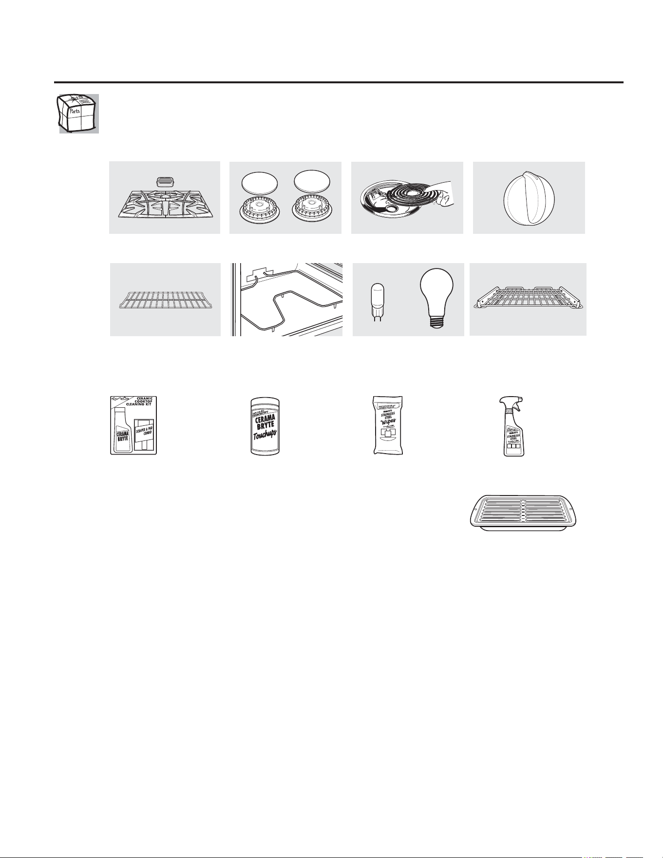
7RSODFH\RXURUGHUFDOO86&DQDGDRUPDLOWKLVIRUPWR
,QWKH86*(3DUWV32%R[0HPSKLV71,Q&DQDGD*(3DUWV)DFWRU\/DQH0RQFWRQ1%(&0
%URLOHU3DQ2UGHU)RUP
4XDQWLW\BBBBBBBBBBBBBBBBBBBB 3DUW1XPEHU BBBBBBBBBBBBBBBBBBBBBBBBBBBBBBBBBBBBBBBBBBBBBBBBBB
BBBBBBBBBBBBBBBBBBBB BBBBBBBBBBBBBBBBBBBBBBBBBBBBBBBBBBBBBBBBBBBBBBBBBBBBBBBBBBBBBB
BBBBBBBBBBBBBBBBBBBB BBBBBBBBBBBBBBBBBBBBBBBBBBBBBBBBBBBBBBBBBBBBBBBBBBBBBBBBBBBBBB
0RGHO1XPEHUBBBBBBBBBBBBBB 6HULDO1XPEHU BBBBBBBBBBBBBBBBBB %UDQG BBBBBBBBBBBBBBB 'DWHRI3XUFKDVHBBBBBBBBBB
)LUVW1DPHBBBBBBBBBBBBBBBBBBBBBBBBBBBBBBBBBBBBBBBBBBBB /DVW1DPHBBBBBBBBBBBBBBBBBBBBBBBBBBBBBBBBBBBBBBBBBBBBBB
$GGUHVVBBBBBBBBBBBBBBBBBBBBBBBBBBBBBBBBBBBBBBBBBBBBBBBBBBBBBBBBBBBBBBBBBBBBBBBBBBBBBBBBBBBBBBBBBBBBBBBBBBBBBBBBBB
&LW\BBBBBBBBBBBBBBBBBBBBBBBBBBBBBBBBBBBBBBBBBBBBBBBBBB 6WDWHBBBBBBBBBBB =LS&RGHBBBBBBBBBBBBBBBBBBBBBBBBBBBBB
3KRQHBBBBBBBBBBBBBBBBBBBBBBBBBBBBBBBBBBBBBBBBBBBBBBBB (0DLO BBBBBBBBBBBBBBBBBBBBBBBBBBBBBBBBBBBBBBBBBBBBBBBBBB
&KHFN BBBBBB 0RQH\2UGHUBBBBBB
&DOOLQWKH86RULQ&DQDGDIRUFXUUHQWSULFLQJ$OOFUHGLWFDUGRUGHUVPXVWEHFDOOHGLQ
$FFHVVRULHV
*($SSOLDQFHVFRP
/RRNLQJ)RU6RPHWKLQJ0RUH"1RWDOODFFHVVRULHVDUHDYDLODEOHIRUDOOPRGHOV
<RXFDQILQGWKHVHDFFHVVRULHVDQGPDQ\PRUHDW*($SSOLDQFHVFRP86
RUZZZ*($SSOLDQFHVFD&DQDGDRUFDOO86RU&DQDGD
GXULQJQRUPDOEXVLQHVVKRXUV+DYH\RXUPRGHOQXPEHUUHDG\
([SHULHQFHWKHVHRWKHUJUHDWSURGXFWVWRNHHS\RXUNLWFKHQORRNLQJJUHDW
*HWWKHPRVWRXWRI\RXU%URLOHU3DQ1RWIRUXVHZLWK%URLOHU'UDZHUPRGHOV
8VH\RXUSDQDQGJULGFRYHUWREURLOKDPEXUJHUVVHDIRRGVWHDNVYHJHWDEOHVEDFRQFKRSVDQGVRPXFKPRUH7KHSDQEHORZFDWFKHV
WKHH[FHVVIDWVDQGRLOV
*HQXLQH*(3DUW
(DV\7R&OHDQ
2QH<HDU:DUUDQW\
/LPLWHG7LPH2IIHU)UHH6KLSSLQJ
:KHQ\RXRUGHU\RXUEURLOHUSDQZLWKLQGD\VRISXUFKDVLQJ\RXU*(FRRNLQJSURGXFW
6PDOO /DUJH ;/
863DUW :%; :%; :%;
'LPHQVLRQV µ:[µ+[µ' µ:[µ+[µ' µ:[µ+[µ'
7KHODUJHVWDQGDUGEURLOSDQGRHVQRWILWLQµµUDQJHV
7KH;/SDQGRHVQRWILWLQµZDOORYHQVµGURSLQVRUµµUDQJHV
6XUIDFH(OHPHQWVDQG'ULS3DQV
*UDWHV 6XUIDFH%XUQHU+HDGVDQG&DSV
2YHQ(OHPHQWV /LJKW%XOEV ([WHQVLRQ5DFN
.QREV
2YHQ5DFNV
BBBBBBBBBBBBBBBBBBBBBBBBBBBBBBBBBBBBBBBBBBBBBBBBBBBBBBB
RU
:;;*&6
:;;
:;;
30;
&HUDPLF
&RRNWRS
&OHDQLQJ.LW
,QFOXGHVFOHDQHU
VFUDSHUDQGSDG
&HUDPLF&RRNWRS
&OHDQLQJ:LSHV
6WDLQOHVV6WHHO
$SSOLDQFH3ROLVK
:LSHV
6WDLQOHVV6WHHO
$SSOLDQFH
&OHDQHU
,I\RXUPRGHOLQFOXGHGDQH[WHQVLRQUDFN\RXFDQLQFUHDVHWKH
IXQFWLRQDOLW\RI\RXUUDQJHZ
KHQ\RXSXUFKDVHDGGLWLRQDOH[WHQVLRQUDFNV9LVLW
ZZZJHDSSOLDQFHSDUWVFRPRUFDOODQGRUGHUSDUWQXPEHU:%73OHDVHQRWHH[WHQVLRQUDFNVGRQRWILWDOOPRGHOUDQJHV
✁

1RWHV

*((OHFWULF5DQJH:DUUDQW\
*($SSOLDQFHVFRP
6HUYLFHWULSVWR\RXUKRPHWRWHDFK\RXKRZWRXVH
WKHSURGXFW
,PSURSHULQVWDOODWLRQGHOLYHU\RUPDLQWHQDQFH
3URGXFWGDPDJHRUIDLOXUHRIWKHSURGXFWLILWLVDEXVHG
PLVXVHGPRGLILHGXVHGIRURWKHUWKDQWKHLQWHQGHG
SXUSRVHRUXVHGFRPPHUFLDOO\
'DPDJHWRWKHJODVVFRRNWRSFDXVHGE\XVHRIFOHDQHUV
RWKHUWKDQWKHUHFRPPHQGHGFOHDQLQJFUHDPVDQGSDGV
'DPDJHWRWKHJODVVFRRNWRSFDXVHGE\KDUGHQHGVSLOOV
RIVXJDU\PDWHULDOVRUPHOWHGSODVWLFWKDWDUHQRWFOHDQHG
DFFRUGLQJWRWKHGLUHFWLRQVLQWKH2ZQHU·V0DQXDO
5HSODFHPHQWRIKRXVHIXVHVRUUHVHWWLQJRIFLUFXLWEUHDNHUV
'DPDJHWRWKHSURGXFWFDXVHGE\DFFLGHQWILUHIORRGVRU
DFWVRI*RG
,QFLGHQWDORUFRQVHTXHQWLDOGDPDJHFDXVHGE\SRVVLEOH
GHIHFWVZLWKWKLVDSSOLDQFH
'DPDJHFDXVHGDIWHUGHOLYHU\
3URGXFWQRWDFFHVVLEOHWRSURYLGHUHTXLUHGVHUYLFH
:KDW*(:LOO1RW&RYHU
7KLVZDUUDQW\LVH[WHQGHGWRWKHRULJLQDOSXUFKDVHUDQGDQ\VXFFHHGLQJRZQHUIRUSURGXFWVSXUFKDVHGIRUKRPH
XVHZLWKLQWKH86$,IWKHSURGXFWLVORFDWHGLQDQDUHDZKHUHVHUYLFHE\D*($XWKRUL]HG6HUYLFHULVQRWDYDLODEOH\RX
PD\EHUHVSRQVLEOHIRUDWULSFKDUJHRU\RXPD\EHUHTXLUHGWREULQJWKHSURGXFWWRDQ$XWKRUL]HG*(6HUYLFHORFDWLRQIRU
VHUYLFH,Q$ODVNDWKHZDUUDQW\H[FOXGHVWKHFRVWRIVKLSSLQJRUVHUYLFHFDOOVWR\RXUKRPH
6RPHVWDWHVGRQRWDOORZWKHH[FOXVLRQRUOLPLWDWLRQRILQFLGHQWDORUFRQVHTXHQWLDOGDPDJHV7KLVZDUUDQW\JLYHV
\RXVSHFLILFOHJDOULJKWVDQG\RXPD\DOVRKDYHRWKHUULJKWVZKLFKYDU\IURPVWDWHWRVWDWH7RNQRZZKDW\RXU
OHJDOULJKWVDUHFRQVXOW\RXUORFDORUVWDWHFRQVXPHUDIIDLUVRIILFHRU\RXUVWDWH·V$WWRUQH\*HQHUDO
:DUUDQWRU*HQHUDO(OHFWULF&RPSDQ\/RXLVYLOOH.<
$OOZDUUDQW\VHUYLFHSURYLGHGE\RXU)DFWRU\6HUYLFH&HQWHUV
RUDQDXWKRUL]HG&XVWRPHU&DUH
WHFKQLFLDQ7RVFKHGXOH
VHUYLFHYLVLWXVRQOLQHDW*($SSOLDQFHVFRPRUFDOO
*(&$5(63OHDVHKDYHVHULDOQXPEHU
DQGPRGHOQXPEHUDYDLODEOHZKHQFDOOLQJIRUVHUYLFH
6WDSOH\RXUUHFHLSWKHUH
3URRIRIWKHRULJLQDOSXUFKDVH
GDWHLVQHHGHGWRREWDLQVHUYLFH
XQGHUWKHZDUUDQW\
(;&/86,212),03/,(':$55$17,(6³<RXUVROHDQGH[FOXVLYHUHPHG\LVSURGXFWUHSDLUDVSURYLGHGLQWKLV/LPLWHG
:DUUDQW\$Q\LPSOLHGZDUUDQWLHVLQFOXGLQJWKHLPSOLHGZDUUDQWLHVRIPHUFKDQWDELOLW\RUILWQHVVIRUDSDUWLFXODUSXUSRVH
DUHOLPLWHGWRRQH\HDURUWKHVKRUWHVWSHULRGDOORZHGE\ODZ
)RU7KH3HULRG2I *(:LOO3URYLGH
2QH<HDU $Q\SDUWRIWKHUDQJHZKLFKIDLOVGXHWRDGHIHFWLQPDWHULDOVRUZRUNPDQVKLS
)URPWKHGDWHRIWKH 'XULQJWKLVOLPLWHGRQH\HDUZDUUDQW\*(ZLOODOVRSURYLGHIUHHRIFKDUJHDOOODERUDQGLQKRPH
RULJLQDOSXUFKDVH VHUYLFHWRUHSODFHWKHGHIHFWLYHSDUW
)RU3URILOH0RGHOV )RU3URILOH0RGHOV
)LYH<HDUV $UHSODFHPHQWJODVVFRRNWRSLILWVKRXOGFUDFNGXHWRWKHUPDOVKRFNGLVFRORURULIWKHSDWWHUQ
)URPWKHGDWHRIWKH ZHDUVRII
RULJLQDOSXUFKDVH $UHSODFHPHQWUDGLDQWVXUIDFHHOHPHQWLILWVKRXOGEXUQRXW
'XULQJWKLVOLPLWHGDGGLWRQDOIRXU\HDUZDUUDQW\\RXZLOOEHUHVSRQVLEOHIRUDQ\ODERURU
LQKRPHVHUYLFH
&RQVXPHU6XSSRUW
*($SSOLDQFHV:HEVLWH
*($SSOLDQFHVFRP
+DYHDTXHVWLRQRUQHHGDVVLVWDQFHZLWK\RXUDSSOLDQFH"7U\WKH*($SSOLDQFHV:HEVLWHKRXUVDGD\
DQ\GD\RIWKH\HDU)RUJUHDWHUFRQYHQLHQFHDQGIDVWHUVHUYLFH\RXFDQQRZGRZQORDG2ZQHU·V0DQXDOV
RUGHUSDUWVRUHYHQVFKHGXOHVHUYLFHRQOLQH
6FKHGXOH6HUYLFH *($SSOLDQFHVFRP
([SHUW*(UHSDLUVHUYLFHLVRQO\RQHVWHSDZD\IURP\RXUGRRU*HWRQOLQHDQGVFKHGXOH\RXUVHUYLFHDW
\RXUFRQYHQLHQFHDQ\GD\RIWKH\HDU2UFDOO*(&$5(6GXULQJQRUPDOEXVLQHVVKRXUV
5HDO/LIH'HVLJQ6WXGLR *($SSOLDQFHVFRP
*(VXSSRUWVWKH8QLYHUVDO'HVLJQFRQFHSW³SURGXFWVVHUYLFHVDQGHQYLURQPHQWVWKDWFDQEHXVHGE\
SHRSOHRIDOODJHVVL]HVDQGFDSDELOLWLHV:HUHFRJQL]HWKHQHHGWRGHVLJQIRUDZLGHUDQJHRISK\VLFDODQG
PHQWDODELOLWLHVDQGLPSDLUPHQWV)RUGHWDLOVRI*(·V8QLYHUVDO'HVLJQDSSOLFDWLRQVLQFOXGLQJNLWFKHQGHVLJQ
LGHDVIRUSHRSOHZLWKGLVDELOLWLHVFKHFNRXWRXU:HEVLWHWRGD\)RUWKHKHDULQJLPSDLUHGSOHDVHFDOO7''
*($&
([WHQGHG:DUUDQWLHV *($SSOLDQFHVFRP
3XUFKDVHD*(H[WHQGHGZDUUDQW\DQGOHDUQDERXWVSHFLDOGLVFRXQWVWKDWDUHDYDLODEOHZKLOH\RXUZDUUDQW\
LVVWLOOLQHIIHFW<RXFDQSXUFKDVHLWRQOLQHDQ\WLPHRUFDOOGXULQJQRUPDOEXVLQHVVKRXUV
*(&RQVXPHU+RPH6HUYLFHVZLOOVWLOOEHWKHUHDIWHU\RXUZDUUDQW\H[SLUHV
3DUWVDQG$FFHVVRULHV *($SSOLDQFHVFRP
,QGLYLGXDOVTXDOLILHGWRVHUYLFHWKHLURZQDSSOLDQFHVFDQKDYHSDUWVRUDFFHVVRULHVVHQWGLUHFWO\WRWKHLUKRPHV
9,6$0DVWHU&DUGDQG'LVFRYHUFDUGVDUHDFFHSWHG2UGHURQOLQHWRGD\KRXUVHYHU\GD\RUE\SKRQHDW
GXULQJQRUPDOEXVLQHVVKRXUV
,QVWUXFWLRQVFRQWDLQHGLQWKLVPDQXDOFRYHUSURFHGXUHVWREHSHUIRUPHGE\DQ\XVHU2WKHUVHUYLFLQJ
JHQHUDOO\VKRXOGEHUHIHUUHGWRTXDOLILHGVHUYLFHSHUVRQQHO&DXWLRQPXVWEHH[HUFLVHGVLQFHLPSURSHU
VHUYLFLQJPD\FDXVHXQVDIHRSHUDWLRQ
&RQWDFW8V *($SSOLDQFHVFRP
,I\RXDUHQRWVDWLVILHGZLWKWKHVHUYLFH\RXUHFHLYHIURP*(FRQWDFWXVRQRXU:HEVLWHZLWKDOOWKHGHWDLOV
LQFOXGLQJ\RXUSKRQHQXPEHURUZULWHWR *HQHUDO0DQDJHU&XVWRPHU5HODWLRQV
*($SSOLDQFHV$SSOLDQFH3DUN
/RXLVYLOOH.<
5HJLVWHU<RXU$SSOLDQFH *($SSOLDQFHVFRP
5HJLVWHU\RXUQHZDSSOLDQFHRQOLQH³DW\RXUFRQYHQLHQFH7LPHO\SURGXFWUHJLVWUDWLRQZLOODOORZIRUHQKDQFHG
FRPPXQLFDWLRQDQGSURPSWVHUYLFHXQGHUWKHWHUPVRI\RXUZDUUDQW\VKRXOGWKHQHHGDULVH
<RXPD\DOVRPDLOLQWKHSUHSULQWHGUHJLVWUDWLRQFDUGLQFOXGHGLQWKHSDFNLQJPDWHULDO

63*(
*($SSOLDQFHVFRP
(VFULEDORVQ~PHURVGHPRGHOR\GHVHULHDTXt
0RGHORBBBBBBBBBBBBBBB
6HULHBBBBBBBBBBBBBBBBB
3XHGHHQFRQWUDUORVHQXQDHWLTXHWDXELFDGDGHWUiV
GHOFDMyQRGHWUiVGHODSXHUWDGHOKRUQRLQIHULRUHQ
HOIUHQWHGHOPDUFRGHODFRFLQD
4XLFN6HW9
4XLFN6HW9,
0DQXDOGHO
3URSLHWDULR
&RFLQDV
,QVWUXFFLRQHVGH6HJXULGDG ²
,QVWUXFFLRQHVGH2SHUDFLyQ
+RUQR
7HPSRUL]DGRUGHOD&RFLQD
$MXVWHGHOWHUPRVWDWRGHOKRUQR
$VDGR*XtDGHDVDGR
$XWROLPSLH]D
)XQFLRQHVSDUD3UREDU\&DOHQWDU
&DUDFWHUtVWLFDVHVSHFLDOHV
&RQWUROHV
)XQFLyQ6DEEDWK
+RUQHDGRRURVWL]DGR
+RUQHDGR\URVWL]DGRFRQWHPSRUL]DGRU
+RUQRGHFRQYHFFLyQ
3UHFDOHQWDPLHQWR
6RQGD
7HPSRUL]DGRUGHFRFLQD
8QLGDGHVGHVXSHUILFLH²
ÈUHDSDUD&DOHQWDU
(VWXIDGH9LGULR5DGLDQWH
4XHPDGRUGHO3XHQWH
6HOHFFLRQDUWLSRVGHXWHQVLOLRV
&XLGDGR\OLPSLH]D
%DQGHMDV
&DMyQGHDOPDFHQDPLHQWR
(OHPHQWRVFDOHQWDGRUHVGHOKRUQR
(VWXIDGHYLGULR
/X]
3DQHOGHFRQWURO
3DSHOGHDOXPLQLR
3HULOODVGHFRQWURO
3LVRGHOKRUQR
3XHUWDGHOKRUQRGHVPRQWDEOH
6XSHUILFLHV
9HQWLODFLyQ
&RQVHMRVSDUDODLGHQWLILFDFLyQ
\VROXFLyQGHSUREOHPDV
$FFHVRULRV
$SR\RDOFOLHQWH
$SR\RDOFOLHQWH
*DUDQWtD
,PSUHVRHQ
SDSHOUHFLFODGR
HOpFWULFDVLQGHSHQGLHQWHVHPSRWUDEOHV\HQFDVWUDEOHV
(Q&DQDGi
ZZZ*($SSOLDQFHVFD
,PSUHVRHQORV(VWDGRV8QLGRV
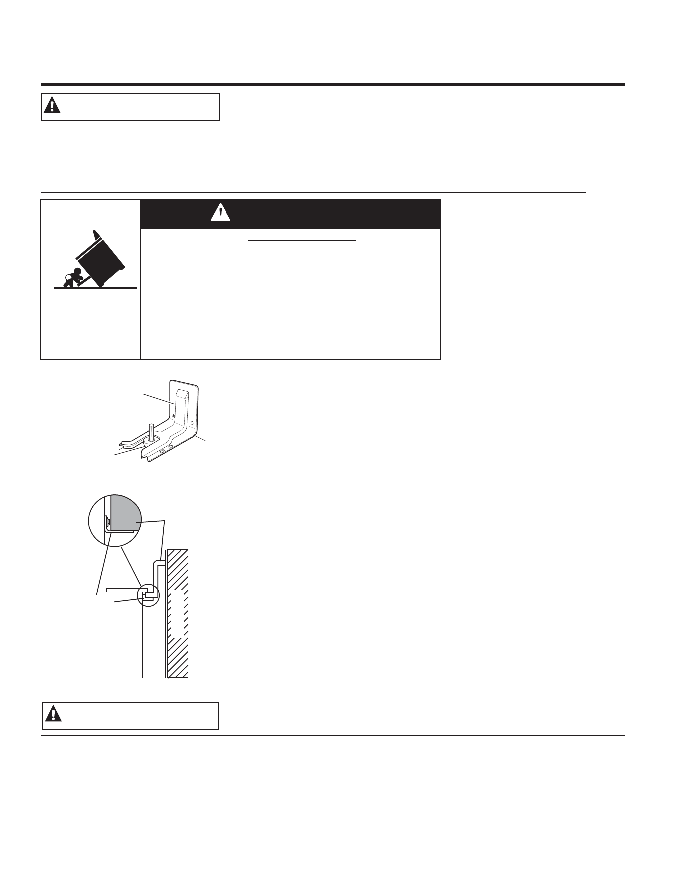
/HDWRGDVODVLQVWUXFFLRQHVGHVHJXULGDGDQWHVGHXWLOL]DUHVWHSURGXFWR1RVHJXLUHVWDVLQVWUXFFLRQHVSXHGHJHQHUDUXQ
LQFHQGLRXQDGHVFDUJDHOpFWULFDOHVLRQHVFRUSRUDOHVRODPXHUWH
127,),&$&,Ï1,03257$17('(6(*85,'$'
/DOH\GH&DOLIRUQLDVREUHDJXDVSRWDEOHV\Wy[LFRVH[LJHTXHHO*REHUQDGRUGH&DOLIRUQLDSXEOLTXHXQDOLVWDGHVXVWDQFLDVTXHVHJ~Q
HOHVWDGRSURYRTXHQFiQFHUGHIHFWRVFRQJpQLWRVXRWURVGDxRVUHSURGXFWLYRV\H[LJHDODVHPSUHVDVTXHDGYLHUWDQDORVFOLHQWHV
VREUHODH[SRVLFLyQSRWHQFLDODGLFKDVVXVWDQFLDV
/DDLVODFLyQGHILEUDGHYLGULRGHORVKRUQRVDXWROLPSLDQWHVHPLWHXQDSHTXHxDFDQWLGDGGHPRQy[LGRGHFDUERQRGXUDQWH
HOFLFORGHOLPSLH]D/DH[SRVLFLyQSXHGHPLQLPL]DUVHYHQWLODQGRFRQXQDYHQWDQDDELHUWDRXVDQGRXQDFDPSDQDRYHQWLODGRU
,1)250$&,Ï1,03257$17('(6(*85,'$'
/($72'$6/$6,16758&&,21(6$17(6'(68862
$'9(57(1&,$
$'9(57(1&,$
',6326,7,92$17,92/&$'85$6
3DUDUHGXFLUHOULHVJRGHYROFDU
ODFRFLQDpVWDGHEHVXMHWDUVH
PHGLDQWHXQVRSRUWHDQWL
YROFDGXUDVFRQXQDDGHFXDGD
LQVWDODFLyQ9HUODVLQVWUXFFLRQHVGH
LQVWDODFLyQHQYLDGDVFRQHOVRSRUWH
SDUDREWHQHUGHWDOOHVFRPSOHWRV
DQWHVGHLQLFLDUODLQVWDODFLyQ
3DUD&RFLQDV6LQ$SR\R\
'HVOL]DEOHVV
3DUDFRQWURODUVLHOVRSRUWHHV
LQVWDODGR\DMXVWDGRGHIRUPD
DSURSLDGDPLUHTXHGHEDMRGH
ODFRFLQDODSDWDQLYHODGRUDWUDVHUDHVWpDMXVWDGDDOVRSRUWH(QDOJXQRV
PRGHORVHOFDMyQGHDOPDFHQDPLHQWRRHOSDQHOGHSURWHFFLyQVHSXHGHQ
UHWLUDUSDUDXQDIiFLOLQVSHFFLyQ6LQRHVSRVLEOHUHDOL]DUXQDLQVSHFFLyQ
YLVXDOGHVOLFHODFRFLQDKDFLDDGHODQWHFRQILUPHTXHHOVRSRUWHDQWL
YROFDGXUDVHVWpDMXVWDGRGHIRUPDVHJXUDDOSLVRRODSDUHG\GHVOLFHOD
FRFLQDKDFLDDWUiVGHPRGRTXHODSDWDQLYHODGRUDWUDVHUDVHHQFXHQWUH
GHEDMRGHOVRSRUWHDQWLYROFDGXUDV
6LODFRFLQDHVH[SXOVDGDGHODSDUHGSRUDOJXQDUD]yQVLHPSUHUHSLWDHVWH
SURFHGLPLHQWRDILQGHYHULILFDUTXHHVWpDVHJXUDGRGHIRUPDFRUUHFWDFRQXQ
VRSRUWHDQWLYROFDGXUDV
1XQFDTXLWHODVSDWDVGHQLYHODFLyQSRUFRPSOHWR\DTXHODFRFLQDQR
TXHGDUiELHQVXMHWDDOGLVSRVLWLYRDQWLYROFDGXUDV
&RFLQDV(PSRWUDEOHV
3DUDFRQWURODUVLHOVRSRUWHHVWiLQVWDODGR\FRQHFWDGRFRUUHFWDPHQWH
GHVOLFHODFRFLQDKDFLDDGHODQWHFRQILUPHTXHHOVRSRUWHDQWLYROFDGXUDV
HVWpDGKHULGRGHIRUPDVHJXUDDODSDUWHWUDVHUDGHODFRFLQD\GHVOLFH
HVWD~OWLPDKDFLDDWUiVGHPRGRTXHHOVRSRUWHDQWLYROFDGXUDVVHGHVOLFH
SRUGHEDMRGHOPRVWUDGRUREORTXHGHPDGHUDDGMXQWRDODSDUHGWUDVHUD
6LXVWHGQRUHFLELyXQVRSRUWHDQWLYROFDGXUDVFRQVXFRPSUDOODPHDO
SDUDUHFLELUXQRVLQFRVWRDOJXQRHQ&DQDGiOODPHDO
3DUDFRQVXOWDULQVWUXFFLRQHVGHLQVWDODFLyQGHOVRSRUWH
YLVLWH*($SSOLDQFHVFRPHQ&DQDGi*($SSOLDQFHVFD
Un niño o adulto pueden volcar la cocina y morir.
Verifique que el soporte anti-volcaduras se haya
instalado y ajustado correctamente.
Verifique que el soporte anti-volcaduras se haya
instalado y ajustado correctamente.
No utilice la cocina sin que el soporte anti-volcaduras
esté colocado y ajustado.
Si estas instrucciones no se siguen, como resultado se podrá
producir la muerte o quemaduras graves de niños y adultos.
Riesgo de Volcaduras
ADVERTENCIA
Pared Trasera
Horno
Soporte
Anti-Volcaduras
Base o Bloque de
Madera Negra
&RFLQDV6LQ$SR\R\'HVOL]DEOHV
&RFLQDV(PSRWUDEOHV
6RSRUWH$QWL
9ROFDGXUDV
3DWD1LYHODGRUD
8VHHVWHDSDUDWRVyORFRQHOREMHWLYRSDUDHOTXHIXHFUHDGR
FRPRVHGHVFULEHHQHVWH0DQXDOGHO3URSLHWDULR
$VHJ~UHVHGHTXHXQWpFQLFRFDOLILFDGRUHDOLFHXQDFRUUHFWD
LQVWDODFLyQ\SXHVWDDWLHUUDGHODUWHIDFWRGHDFXHUGRFRQODV
LQVWUXFFLRQHVGHLQVWDODFLyQSURYLVWDV
1RLQWHQWHUHSDUDURFDPELDUQLQJXQDSLH]DGHVXFRFLQDD
PHQRVTXHHVWpHVSHFtILFDPHQWHUHFRPHQGDGRHQHVWHPDQXDO
&XDOTXLHURWURVHUYLFLRGHEHUHDOL]DUORXQWpFQLFRFDOLILFDGR
$QWHVGHUHDOL]DUFXDOTXLHUFODVHGHUHSDUDFLyQGHVHQFKXIHOD
FRFLQDRGHVFRQHFWHHOVXPLQLVWURHOpFWULFRGHVGHHOSDQHOGH
GLVWULEXFLyQGRPpVWLFRTXLWDQGRHOIXVLEOHRGHVFRQHFWDQGRHO
LQWHUUXSWRUGHFLUFXLWRV
1RGHMHDORVQLxRVVRORVpVWRVQRGHEHQTXHGDUVRORVRVLQ
DWHQFLyQHQXQiUHDGRQGHXQDSDUDWRHVWpHQXVR1XQFDGHEH
SHUPLWLUVHTXHVHVXEDQVLHQWHQRSDUHQHQFXDOTXLHUSDUWHGH
HVWHDSDUDWR
35(&$8&,211RDOPDFHQHHOHPHQWRVGHLQWHUpV
SDUDQLxRVVREUHXQDFRFLQDRHQODSURWHFFLyQWUDVHUDGH
XQDFRFLQDORVQLxRVTXHVHWUHSDQDODFRFLQDSDUDDOFDQ]DU
HOHPHQWRVSXHGHQUHVXOWDUJUDYHPHQWHKHULGRV
6yORXVHDJDUUDGHUDVVHFDVODVDJDUUDGHUDVK~PHGDVR
PRMDGDVFRORFDGDVHQVXSHUILFLHVFDOLHQWHVSXHGHQSURYRFDU
TXHPDGXUDVGHYDSRU1RSHUPLWDTXHODVDJDUUDGHUDVHQWUHQ
HQFRQWDFWRFRQXQLGDGHVGHVXSHUILFLHRORVHOHPHQWRV
FDOHQWDGRUHVFDOLHQWHV1RXWLOLFHWRDOODV
XRWUDVWHODVJUXHVDVHQOXJDUGHXQDDJDUUDGHUD
1XQFDXVHVXHOHFWURGRPpVWLFRSDUDFDOHQWDUODKDELWDFLyQ
1RWRTXHODVXQLGDGHVGHVXSHUILFLHORVHOHPHQWRVFDOHQWDGRUHV
RODVXSHUILFLHLQWHULRUGHOKRUQR(VWDVVXSHUILFLHVSXHGHQHVWDU
ORVXILFLHQWHPHQWHFDOLHQWHVSDUDTXHPDUD~QFXDQGRWHQJDQ
XQFRORURVFXUR'XUDQWH\GHVSXpVGHOXVRQRWRTXHRGHMHTXH
VXYHVWLPHQWDXRWURVPDWHULDOHVLQIODPDEOHVHQWUHQHQFRQWDFWR
FRQXQLGDGHVGHVXSHUILFLHiUHDVFHUFDQDVDODVXQLGDGHVGH
VXSHUILFLHRFXDOTXLHUiUHDLQWHULRUGHOKRUQRGHMHSDVDUXQ
WLHPSRSUXGHQFLDOSDUDTXHVHHQIUtHQ2WUDVVXSHUILFLHVGHO
DSDUDWRSXHGHQFDOHQWDUVHORVXILFLHQWHFRPRSDUDSURYRFDU
TXHPDGXUDV/DVVXSHUILFLHVSRWHQFLDOPHQWHFDOLHQWHVLQFOX\HQ
ODHVWXIDODViUHDVRULHQWDGDVKDFLDODHVWXIDODDEHUWXUDGH
YHQWLODFLyQGHOKRUQRODVVXSHUILFLHVFHUFDQDVDODDEHUWXUD\ODV
KHQGLGXUDVXELFDGDVDOUHGHGRUGHODSXHUWDGHOKRUQR
1RFDOLHQWHUHFLSLHQWHVFHUUDGRVGHDOLPHQWRV3RGUtDKDEHUXQD
DFXPXODFLyQGHSUHVLyQHQHOUHFLSLHQWH\pVWHSRGUtDH[SORWDU
SURYRFDQGROHVLRQHV
1RXWLOLFHSDSHOGHDOXPLQLRSDUDUHYHVWLUODVEDQGHMDVFROHFWRUDV
RQLQJXQDSDUWHGHOKRUQRFRQH[FHSFLyQGHORGHVFULSWRHQHVWH
PDQXDO8QXVRLQDGHFXDGRSXHGHSURYRFDUGDxRVDODFRFLQD\
XQDGHVFDUJDHOpFWULFDRXQULHVJRGHLQFHQGLR
7UDWHGHQRUD\DURJROSHDUODVSXHUWDVHVWXIDVRSDQHOHV
GHFRQWUROGHYLGULR6LORKDFHSRGUtDURPSHUVHHOYLGULR1R
FRFLQHVLXQSURGXFWRWLHQHXQYLGULRURWR3XHGHSURYRFDUVHXQD
GHVFDUJDXQLQFHQGLRRKHULGDV
&RFLQHFDUQHVGHUHV\GHDYHSRUFRPSOHWR/DVFDUQHVGH
UHVKDVWDDOFDQ]DUXQDWHPSHUDWXUDLQWHUQDGHSRUORPHQRV
)&\ODVFDUQHVGHDYHDXQDWHPSHUDWXUDLQWHUQDGH
SRUORPHQRV)&/DFRFFLyQDHVWDVWHPSHUDWXUDV
JHQHUDOPHQWHSURWHJHGHHQIHUPHGDGHVWUDQVPLWLGDVSRUORV
DOLPHQWRV
1RDOPDFHQHRXWLOLFHPDWHULDOHVLQIODPDEOHVGHQWURGHXQKRUQR
RFHUFDGHODHVWXIDWDOHVFRPRSDSHOSOiVWLFRDJDUUDGHUDV
WHODVUHFXEULPLHQWRVGHSDUHGFRUWLQDV\JDVROLQDXRWURV
YDSRUHV\OtTXLGRVLQIODPDEOHV
1XQFDXVHYHVWLPHQWDVKROJDGDVRDPSOLDVPLHQWUDVXWLOLFHHO
DSDUDWR(VWDVYHVWLPHQWDVSXHGHQSUHQGHUVHIXHJRVLHQWUDQ
HQFRQWDFWRFRQVXSHUILFLHVFDOLHQWHVSURYRFDQGRTXHPDGXUDV
JUDYHV
1RSHUPLWDTXHODJUDVDGHODFRFFLyQXRWURVPDWHULDOHV
LQIODPDEOHVVHDFXPXOHQGHQWURGHODFRFLQDRHQVXFHUFDQtD/D
JUDVDGHQWURGHOKRUQRRVREUHODHVWXIDSXHGHHQFHQGHUVH
/LPSLHODVFDPSDQDVGHYHQWLODFLyQFRQIUHFXHQFLD1RGHEH
SHUPLWLUVHODDFXPXODFLyQGHJUDVDHQODFDPSDQDRHQHOILOWUR
*($SSOLDQFHVFRP
1RXWLOLFHDJXDHQLQFHQGLRVGHJUDVD1XQFDOHYDQWHXQDVDUWpQ
HQOODPDV$SDJXHORVFRQWUROHV$SDJXHXQDVDUWpQHQOODPDV
VREUHXQDXQLGDGGHVXSHUILFLHFXEULHQGRODVDUWpQSRUFRPSOHWR
FRQXQDWDSDTXHDMXVWHELHQXQDSODQFKDSDUDJDOOHWDVRXQD
EDQGHMDSODQD8WLOLFHXQTXtPLFRVHFRPXOWLXVRRXQH[WLQWRUGH
LQFHQGLRVGHHVSXPD
6LKD\XQLQFHQGLRHQHOKRUQRGXUDQWHHOKRUQHDGRDSiJXHOR
FHUUDQGRODSXHUWDGHOKRUQR\DSDJDQGRHOFRQWURORXVDQGRXQ
TXtPLFRVHFRPXOWLXVRRXQH[WLQWRUGHLQFHQGLRVGHHVSXPD
6LKD\XQLQFHQGLRHQHOKRUQRGXUDQWHODDXWROLPSLH]D
DSDJXHHOKRUQR\HVSHUHDTXHHOLQFHQGLRVHFRQVXPD1R
DEUDODSXHUWDGHOKRUQRDODIXHU]D(OLQJUHVRGHDLUHIUHVFRD
WHPSHUDWXUDVGHDXWROLPSLH]DSXHGHSURYRFDUXQDH[SORVLyQ
GHOODPDVGHVGHHOKRUQR1RVHJXLUHVWDLQVWUXFFLyQSXHGH
SURYRFDUTXHPDGXUDVJUDYHV
,16758&&,21(6*(1(5$/(6'(6(*85,'$'
$'9(57(1&,$
0$17(1*$/260$7(5,$/(6
,1)/$0$%/(6$/(-$'26'(/$&2&,1$
$'9(57(1&,$
(1&$62'(,1&(1',26,*$/26
6,*8,(17(63$6263$5$(9,7$5
/$3523$*$&,Ï1'(/)8(*2
$'9(57(1&,$
,1)250$&,Ï1,03257$17('(6(*85,'$'
/($72'$6/$6,16758&&,21(6$17(6'(68862
1XQFDGHMHODVXQLGDGHVGHVXSHUILFLHVLQDWHQFLyQ
HQFRQILJXUDFLRQHVGHFDORUPHGLDRDOWD/RVDOLPHQWRVTXH
KLHUYHQ\VHGHUUDPDQSXHGHQSURYRFDUKXPR\GHUUDPHV
JUDVRVRVTXHSXHGHQSUHQGHUVHIXHJR
1XQFDGHMHDFHLWHVLQDWHQFLyQPLHQWUDVIUtH6LVHGHMD
FDOHQWDUPiVDOOiGHOSXQWRGHKXPHRHODFHLWHSXHGH
HQFHQGHUVHSURYRFDQGRXQLQFHQGLRTXHSRGUtDSURSDJDUVH
DORVJDELQHWHVFHUFDQRV8WLOLFHXQWHUPyPHWURSDUDJUDVD
FXDQGRVHDSRVLEOHSDUDFRQWURODUODWHPSHUDWXUDGHODFHLWH
3DUDHYLWDUHOGHUUDPHGHDFHLWH\XQLQFHQGLRXWLOLFHXQD
FDQWLGDGPtQLPDGHDFHLWHFXDQGRIUtDHQVDUWHQHVSRFR
SURIXQGDV\HYLWHODFRFFLyQGHDOLPHQWRVFRQJHODGRVFRQ
XQDFDQWLGDGH[FHVLYDGHKLHOR
8WLOLFHHOWDPDxRGHUHFLSLHQWHDGHFXDGR(OLMDUHFLSLHQWHV
FRQEDVHVSODQDVORVXILFLHQWHPHQWHJUDQGHVSDUDFXEULU
HOHOHPHQWRFDOHQWDGRUGHVXSHUILFLH/DXWLOL]DFLyQGH
UHFLSLHQWHVPiVSHTXHxRVGHMDUiH[SXHVWDXQDSRUFLyQGH
ODXQLGDGGHVXSHUILFLHDOFRQWDFWRGLUHFWRORTXHSXHGH
SURYRFDUHOHQFHQGLGRGHVXVYHVWLPHQWDV
8QDUHODFLyQDGHFXDGDGHOUHFLSLHQWHFRQODXQLGDG
GHVXSHUILFLHWDPELpQPHMRUDUiODHILFLHQFLD
6yORFLHUWRVWLSRVGHUHFLSLHQWHVGHYLGULRYLGULRFHUiPLFR
FHUiPLFDXRWURVUHFLSLHQWHVYLGULDGRVSXHGHQXWLOL]DUVH
VREUHODHVWXIDRWURVSXHGHQURPSHUVHGHELGRDOFDPELR
UHSHQWLQRGHWHPSHUDWXUD
3DUDPLQLPL]DUODSRVLELOLGDGGHTXHPDGXUDV
HOHQFHQGLGRGHPDWHULDOHVLQIODPDEOHV\ORVGHUUDPHV
ODPDQLMDGHORVUHFLSLHQWHVGHEHQJLUDUVHKDFLDHOFHQWURGH
ODFRFLQDVLQH[WHQGHUVHVREUHQLQJXQDXQLGDG
GHVXSHUILFLHFHUFDQD
6LIODPEHDDOLPHQWRVEDMRODFDPSDQDHQFLHQGD
HOYHQWLODGRU
6LVHSURGXFHXQFRUWHGHOX]HQXQDFRFLQDHOpFWULFD
PLHQWUDVODXQLGDGVXSHUILFLDOHVWiHQ21(QFHQGLGROD
XQLGDGVHYROYHUiDHQFHQGHUFXDQGRUHJUHVHODOX](QFDVR
GHIDOWDGHFRUULHQWHVLQRVHJLUDQWRGDVODVSHULOODVGHOD
XQLGDGGHVXSHUILFLDODODSRVLFLyQ2))$SDJDGRVHSRGUiQ
LQFHQGLDUDUWtFXORVHQRFHUFDGHODHVWXIDORFXDOSRGUi
SURGXFLUOHVLRQHVJUDYHVRODPXHUWH
7HQJDFXLGDGRDOWRFDUODHVWXID/DVXSHUILFLHGHYLGULRGHOD
HVWXIDUHWHQGUiFDORUGHVSXpVGHTXHORVFRQWUROHVVHKD\DQ
DSDJDGR
1RFRFLQHVREUHXQDHVWXIDURWD6LODHVWXIDVHURPSHODV
VROXFLRQHVGHOLPSLH]D\ORVGHUUDPHVSXHGHQSHQHWUDU
HQODHVWXIDURWD\FUHDUXQULHVJRGHGHVFDUJDHOpFWULFD
&RPXQtTXHVHFRQXQWpFQLFRFDOLILFDGRGHLQPHGLDWR
(YLWHUD\DUODHVWXIDGHYLGULR/DHVWXIDSXHGHUD\DUVHFRQ
HOHPHQWRVWDOHVFRPRFXFKLOORVLQVWUXPHQWRVILORVRVDQLOORVX
RWUDVMR\DV\UHPDFKHVGHODURSD
1RFRORTXHRDOPDFHQHHOHPHQWRVTXHSXHGHQGHUUHWLUVHR
SUHQGHUVHIXHJRVREUHODHVWXIDGHYLGULRD~QFXDQGRQROD
HVWpXVDQGR6LODHVWXIDVHHQFLHQGHHQIRUPDDFFLGHQWDO
SXHGHQSUHQGHUVHIXHJR(OFDORUSURYHQLHQWHGHODHVWXIDR
GHODYHQWLODFLyQGHOKRUQRWDPELpQSXHGHSUHQGHUORVIXHJR
D~QVLHODSDUDWRHVWiDSDJDGR
8VHHOOLPSLDGRUGHHVWXIDVFHUiPLFDV&(5$0$%5<7(
\ODHVSRQMLOODGHOLPSLH]D&(5$0$%5<7(
SDUDOLPSLDU
ODHVWXID(VSHUHKDVWDTXHODHVWXIDVHHQIUtH\ODOX]
LQGLFDGRUDVHDSDJXHDQWHVGHOLPSLDU8QDHVSRQMD
RXQSDxRK~PHGRVVREUHXQDVXSHUILFLHFDOLHQWHSXHGHQ
SURYRFDUTXHPDGXUDVGHYDSRU$OJXQRVOLPSLDGRUHVSXHGHQ
SURGXFLUKXPRVWy[LFRVVLVHORVDSOLFDDXQDVXSHUILFLH
FDOLHQWH127$/RVGHUUDPHVGHD]~FDUVRQODH[FHSFLyQ
eVWRVGHEHQTXLWDUVHPLHQWUDVHVWiQFDOLHQWHVXWLOL]DQGRXQD
DJDUUDGHUD\XQUDVSDGRU3DUDLQVWUXFFLRQHVGHWDOODGDVYHU
ODVHFFLyQ&yPROLPSLDU
ODHVWXIDGHYLGULR
/HD\FXPSODFRQWRGDVODVLQVWUXFFLRQHV\DGYHUWHQFLDVGHOD
HWLTXHWDGHODFUHPDGHOLPSLH]D
1RVXPHUMDRUHPRMHODVXQLGDGHVGHVXSHUILFLH
GHVPRQWDEOHV1RODVFRORTXHHQHOODYDYDMLOODV
1RFRORTXHODVXQLGDGHVGHVXSHUILFLHGHQWURGHOKRUQR
FXDQGRUHDOLFHODDXWROLPSLH]D6LORKDFHSXHGHQOOHJDUD
IDOODUSURYRFDQGRXQSHOLJURGHTXHPDGXUDVRGHLQFHQGLR
3DUDHYLWDUODSRVLELOLGDGGHXQDTXHPDGXUDRGHVFDUJD
HOpFWULFDVLHPSUHYHULILTXHTXHORVFRQWUROHVGHWRGDV
ODVXQLGDGHVGHVXSHUILFLHVHHQFXHQWUHQHQODSRVLFLyQ2))
DSDJDGR\TXHWRGDVODVERELQDVHVWpQIUtDVDQWHV
GHOHYDQWDURTXLWDUXQDXQLGDGGHVXSHUILFLHGHERELQDV
$VHJ~UHVHGHTXHODVEDQGHMDVFROHFWRUDVQRHVWpQFXELHUWDV
\VHHQFXHQWUHQHQVXOXJDU6XDXVHQFLDGXUDQWHODFRFFLyQ
SRGUtDGDxDUODVSLH]DV\HOFDEOHDGRGHODFRFLQD
1RXVHSDSHOGHDOXPLQLRSDUDFXEULUFDFHURODVHQOD
SDUWHLQIHULRU(OSDSHOSXHGHDWUDSDUHOFDORURGHUUHWLUVH
RFDVLRQDQGRGDxRVVREUHHOSURGXFWR\ULHVJRGHGHVFDUJD
HOpFWULFDRLQFHQGLR
,16758&&,21(6'(6(*85,'$''(/$(678)$
$'9(57(1&,$
,16758&&,21(6'(6(*85,'$''(/$
(678)$5$',$17(DOJXQRVPRGHORV
$'9(57(1&,$
,16758&&,21(6'(6(*85,'$''(/$
(678)$'(%2%,1$6
DOJXQRVPRGHORV
$'9(57(1&,$
*($SSOLDQFHVFRP
0DQWpQJDVHDOHMDGRGHODFRFLQDFXDQGRDEUD
ODSXHUWDGHOKRUQR(ODLUH\HOYDSRUFDOLHQWHVTXHVDOHQGHOD
FRFLQDSXHGHQSURYRFDUTXHPDGXUDVHQPDQRVURVWUR\R
RMRV
0DQWHQJDVLQREVWUXFFLRQHVODYHQWLODFLyQGHOKRUQR
0DQWHQJDHOKRUQROLEUHGHDFXPXODFLRQHVGHJUDVD
/DJUDVDGHQWURGHOKRUQRSXHGHSUHQGHUVHIXHJR
6LHPSUHFRORTXHODVEDQGHMDVGHOKRUQRHQODSRVLFLyQ
GHVHDGDPLHQWUDVHOKRUQRHVWpIUtR6LODEDQGHMDGHEH
TXLWDUVHFXDQGRHOKRUQRWRGDYtDHVWiFDOLHQWHQRSHUPLWD
TXHODDJDUUDGHUDWRTXHHOHOHPHQWRFDOHQWDGRUGHOKRUQR
&XDQGRXWLOLFHEROVDVGHFRFFLyQRGHDVDGRHQHOKRUQRVLJD
ODVLQVWUXFFLRQHVGHOIDEULFDQWH
7LUHGHODEDQGHMDGHOKRUQRKDVWDODSRVLFLyQGHWRSH
GHGHWHQFLyQFXDQGRFDUJXHRGHVFDUJXHDOLPHQWRV
GHOKRUQR(VWRD\XGDDHYLWDUTXHPDGXUDVSRUWRFDU
VXSHUILFLHVFDOLHQWHVGHODSXHUWD\ODVSDUHGHVGHOKRUQR
1RGHMHSURGXFWRVFRPRSDSHOXWHQVLOLRVGHFRFLQD
RDOLPHQWRVHQHOKRUQRFXDQGRQRORHVWpXVDQGR
/RVHOHPHQWRVJXDUGDGRVHQHOKRUQRSXHGHQSUHQGHUVH
IXHJR
1RXVHSDSHOGHDOXPLQLRSDUDFXEULUHOIRQGRGHOKRUQR(O
DOXPLQLRSXHGHDWUDSDUHOFDORURGHUUHWLUVHORFXDOSXHGH
GDxDUHOSURGXFWR\SURYRFDUULHVJRGHGHVFDUJDHOpFWULFDR
XQLQFHQGLR
/DFDUDFWHUtVWLFDGHDXWROLPSLH]DIXQFLRQDHQHOKRUQRDWHPSHUDWXUDVORVXILFLHQWHPHQWHHOHYDGDVFRPRSDUDTXHPDUORV
UHVWRVGHDOLPHQWRVTXHTXHGDURQGHQWURGHOKRUQR6LJDHVWDVLQVWUXFFLRQHVSDUDXQDRSHUDFLyQVHJXUD
$QWHVGHLQLFLDUHOFLFORGHDXWROLPSLH]DTXLWHODVROODV
EDQGHMDVGHOKRUQRGHPHWDOEULOODQWH\RWURVXWHQVLOLRV
GHOKRUQR6yORSXHGHQGHMDUVHHQHOKRUQRODVEDQGHMDV
UHYHVWLGDVGHSRUFHODQDJULVRQHJUDV1RXWLOLFHODDXWR
OLPSLH]DSDUDOLPSLDURWUDVSLH]DVFRPREDQGHMDVGHJRWHR
EULOODQWHVRWD]RQHV
$QWHVGHXWLOL]DUHOFLFORGHDXWROLPSLH]DOLPSLHODJUDVD\ORV
GHUUDPHVGHDOLPHQWRVGHOKRUQR8QDFDQWLGDGH[FHVLYDGH
JUDVDSXHGHHQFHQGHUVHJHQHUDQGRGDxRVSRUHOKXPRHQ
VXKRJDU
6LHOPRGRGHDXWROLPSLH]DQRIXQFLRQDDSDJXHHOKRUQR
\GHVFRQHFWHHOVXPLQLVWURGHHQHUJtD/ODPHDXQWpFQLFR
FDOLILFDGRSDUDVROLFLWDUHODUUHJOR
1ROLPSLHODHPSDFDGXUDGHODSXHUWD/DHPSDFDGXUDGH
ODSXHUWDHVHVHQFLDOSDUDXQEXHQVHOODGR'HEHWHQHUVH
FXLGDGRGHQRUHIUHJDUGDxDURPRYHUODHPSDFDGXUD
1RXWLOLFHOLPSLDGRUHVGHKRUQR1RGHEHXWLOL]DUVHQLQJ~Q
OLPSLDGRUFRPHUFLDORUHYHVWLPLHQWRSURWHFWRUGHQLQJXQD
FODVHGHQWURRDOUHGHGRUGHQLQJXQDSLH]DGHOKRUQR
(OREMHWLYRGHOFDMyQFDOHQWDGRUHVPDQWHQHUDOLPHQWRV
FRFLGRVFDOLHQWHVDODWHPSHUDWXUDGHVHUYLFLR3RUGHEDMRGH
ORV)&SXHGHSURGXFLUVHFUHFLPLHQWRGHEDFWHULDVHQ
ORVDOLPHQWRV1RFRORTXHDOLPHQWRVIUtRV
HQHOFDMyQFDOHQWDGRU1RFDOLHQWHDOLPHQWRVSRUPiV
GHKRUDV1RVHJXLUHVWDVLQVWUXFFLRQHVSXHGHSURYRFDU
HQIHUPHGDGHVWUDQVPLWLGDVSRUORVDOLPHQWRV
1RGHMHSURGXFWRVGHSDSHOSOiVWLFRVFRPLGDHQODWDGD
RPDWHULDOHVFRPEXVWLEOHVHQHOFDMyQ3XHGHQSUHQGHUVH
IXHJR
1RWRTXHHOHOHPHQWRFDOHQWDGRURODVXSHUILFLHLQWHUQDGHO
FDMyQ(VWDVVXSHUILFLHVSXHGHQHVWDUORVXILFLHQWHPHQWH
FDOLHQWHVFRPRSDUDSURYRFDUTXHPDGXUDV
7HQJDFXLGDGRDODEULUHOFDMyQ$EUDXQSRFRHOFDMyQ\GHMH
VDOLUHODLUHFDOLHQWH\HOYDSRUDQWHVGHTXLWDURYROYHUD
FRORFDUORVDOLPHQWRV(ODLUH\HOYDSRUFDOLHQWHVTXHVDOHQ
SXHGHQSURYRFDUTXHPDGXUDVHQPDQRVURVWUR\RRMRV
1RXVHSDSHOGHDOXPLQLRSDUDFXEULUHOFDMyQLQIHULRU(OSDSHO
DWUDSDUiHQFDORUGHOIRQGR\DOWHUDUiHOIXQFLRQDPLHQWR
GHOKRUQR(OSDSHOVHSRGUiGHUUHWLU\GDxDUGHIRUPD
SHUPDQHQWHODSDUWHLQIHULRUGHOFDMyQ&XDOTXLHUGDxRSRU
XVRLQDGHFXDGRGHOSDSHOGHDOXPLQLRQRHVWDUiFXELHUWRSRU
ODJDUDQWtDGHOSURGXFWR
,16758&&,21(6'(6(*85,'$''(/+2512
$'9(57(1&,$
,16758&&,21(6'(6(*85,'$''(/
+2512$872/,03,$17(DOJXQRVPRGHORV
$'9(57(1&,$
&$-Ï1&$/(17$'25&$-Ï1'(/+2512
,1)(5,25,16758&&,21(6'(6(*85,'$'
$'9(57(1&,$
DOJXQRVPRGHORV
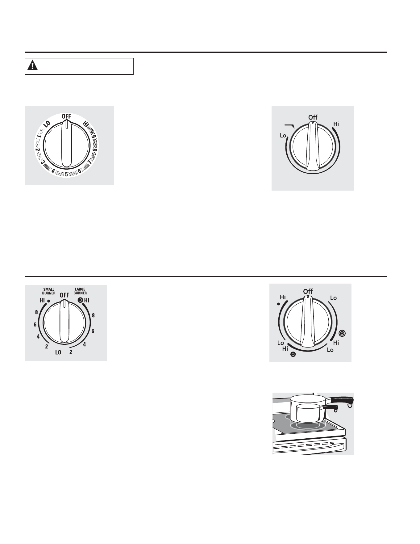
8VRGHXQLGDGHVGHODVXSHUILFLH
5,(6*2'(,1&(1',21XQFDSLHUGDGHYLVWDODFRFLQDFXDQGRODHVWXIDHVWp
HQODVFRQILJXUDFLRQHVPHGLRRDOWR0DQWHQJDORVtWHPVLQIODPDEOHVDOHMDGRV
GHODHVWXID$SDJXHWRGRVORVFRQWUROHVFXDQGRILQDOLFHODFRFFLyQ6LQRVH
VLJXHQHVWDVLQVWUXFFLRQHVVHSRGUiSURGXFLULQFHQGLRVOHVLRQHVJUDYHVRODPXHUWH
(VSRVLEOHTXHODVIXQFLRQHV\DSDULHQFLDVYDUtHQFRQUHODFLyQDVXPRGHORDORODUJRGHOPDQXDO
&yPR&RQILJXUDU
8QLGDGHV6XSHUILFLDOHV'REOHV
\7ULSOHV\3HULOODVGH&RQWURO
HQDOJXQRVPRGHORV
/DXQLGDGGHVXSHUILFLHSRVHHRWDPDxRV
GHFRFFLyQTXHVHSXHGHQVHOHFFLRQDUGH
PRGRTXHSXHGDHQOD]DUHOWDPDxRGHOD
XQLGDGDOWDPDxRGHOXWHQVLOLRTXHHVWpXVDQGR
7DQWRHQ2))$SDJDGR
FRPRHQ+,$OWRHOFRQWURO
VHDMXVWDHQODSRVLFLyQ(V
SRVLEOHTXHHVFXFKHOHYHV
VRQLGRVGHDMXVWHGXUDQWH
ODFRFFLyQLQGLFDQGRTXHHO
FRQWUROHVWiPDQWHQLHQGRVX
FRQILJXUDFLyQGHVHDGD
$VHJ~UHVHGHJLUDUODSHULOOD
GHFRQWUROD2))$SDJDGR
FXDQGRILQDOLFHODFRFFLyQ
0RGHORVFRQXQHOHPHQWRVXSHUILFLDO
GH$QLOOR'REOH~QLFDPHQWH
$'9(57(1&,=$
3UHVLRQHODSHULOODKDFLDDGHQWUR\JLUH
HQFXDOTXLHUDGHODVGLUHFFLRQHVKDVWDOD
FRQILJXUDFLyQTXHGHVHH
8QDOX]LQGLFDGRUDGHGHVXSHUILFLHHQ21
(QFHQGLGREULOODUiFXDQGRXQDXQLGDG
VXSHUILFLDOHVWpHQFHQGLGD
3DUDVXSHUILFLHVGHYLGULRGHODHVWXID
8QDOX]LQGLFDGRUDGH(678)$&$/,(17(
■VHHQFHQGHUiFXDQGRODXQLGDGHVWpFDOLHQWH
DOWDFW
■SHUPDQHFHUiHQFHQGLGDLQFOXVROXHJRGH
TXHODXQLGDGHVWpDSDJDGD
■3HUPDQHFHUiHQFHQGLGDKDVWDTXHODXQLGDG
VHHQIUtHDDSUR[LPDGDPHQWH)
Melt
Rear
8
7
6
54
3
2
9
1
/DFRQILJXUDFLyQ0HOW'HUUHWLUHQDOJXQRV
PRGHORVGHUUHWLUiFKRFRODWHRPDQWHFD
/DFRQILJXUDFLyQ6LPPHU+HUYRU/HQWRHQ
DOJXQRVPRGHORVKHUYLUiVDOVDVDIXHJROHQWR
0RGHORVFRQXQHOHPHQWRVXSHUILFLDO
GH$QLOOR7ULSOH~QLFDPHQWH
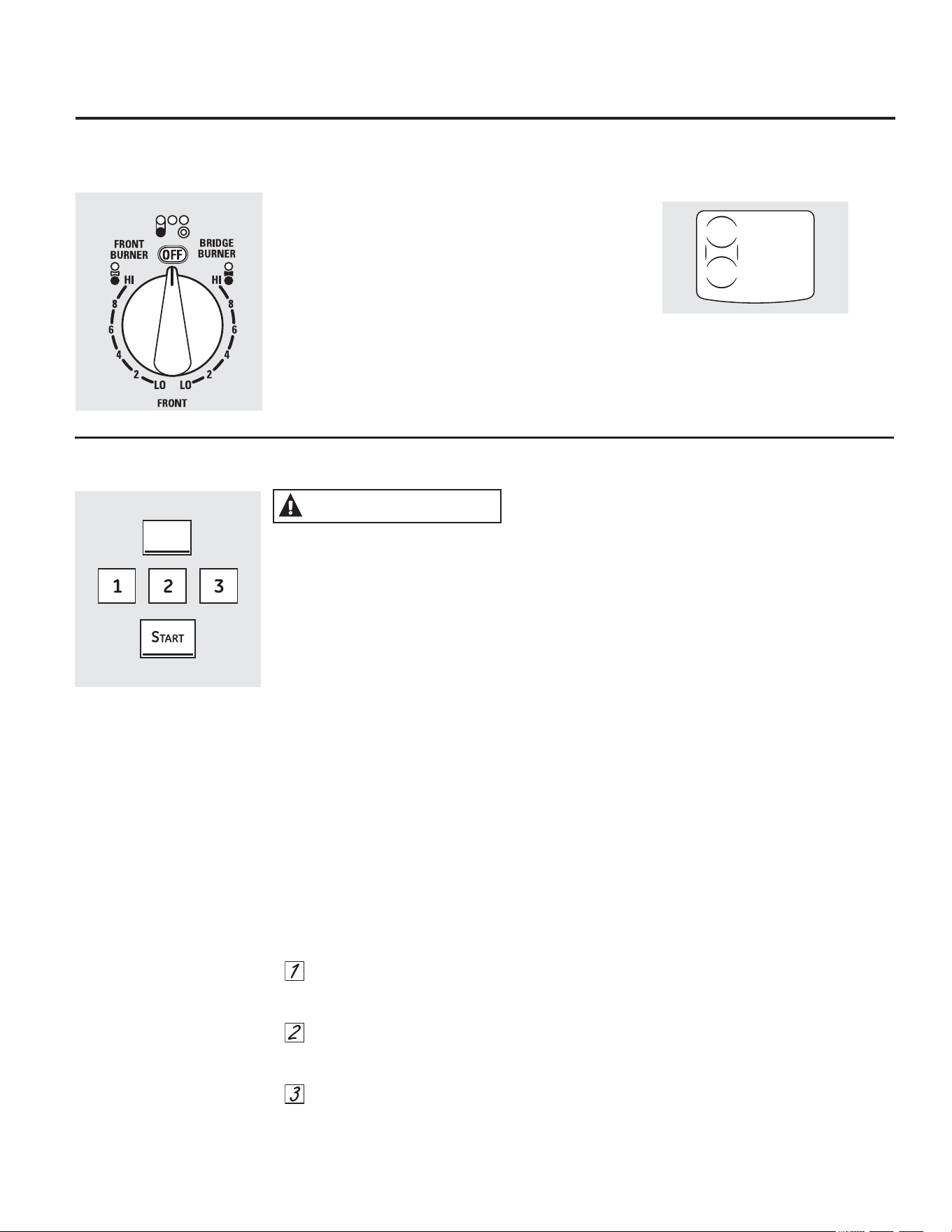
8VRGHOÈUHDSDUD&DOHQWDU
5,(6*2'((19(1(1$0,(172&21&20,'$
6HSXHGHQGHVDUUROODUEDFWHULDVFXDQGROD
FRPLGDHVWpDXQDWHPSHUDWXUDLQIHULRUDORV
■6LHPSUHFRPLHQFHFRQFRPLGDFDOLHQWH1R
XVHFRQILJXUDFLRQHVHQ:$50&DOLHQWH
SDUDFDOHQGDUFRPLGDIUtD
■1RXVHODFRQILJXUDFLyQ:$50&DOHQWDU
GXUDQWHPiVGHKRUDV
6LQRVHVLJXHQHVWDVLQVWUXFFLRQHVVHSRGUiQ
SURGXFLUHQIHUPHGDGHVJHQHUDGDVHQOD
FRPLGD
:$50,1*=21(ÈUHDSDUD&DOHQWDUXELFDGD
HQODSDUWHFHQWUDOWUDVHUDGHODVXSHUILFLHGH
YLGULRPDQWHQGUiODFRPLGDFDOLHQWH\FRFLGDD
ODWHPSHUDWXUDSDUDVHUYLU6LHPSUHFRPLHQFH
FRQFRPLGDFDOLHQWH1RXVHODIXQFLyQSDUD
FDOHQWDUFRPLGDIUtD&RORFDUFRPLGDTXHQR
HVWiFRFLQDGDRIUtDHQHOÈUHDSDUD&DOHQWDU
SRGUtDSURGXFLUHQIHUPHGDGHVGHVDUUROODGDV
SRUEDFWHULDVHQODFRPLGD
3DUDXVDUODIXQFLyQ:$50,1*=21(ÈUHD
SDUD&DOHQWDU
3UHVLRQHODWHFOD:$50,1*=21(21
2))(QFHQGLGR$SDJDGRGHOÈUHDSDUD
&DOHQWDU
3UHVLRQHODWHFODEDMRPHGLRR
DOWRSDUDVHOHFFLRQDUODFRQILJXUDFLyQGH
FRQWUROGHVHDGD
3UHVLRQHODWHFOD67$57,QLFLDU(QOD
SDQWDOODGHFRQWUROVHYLVXDOL]DUi
:$50(5+27210iV&DOLHQWH$FWLYDGR
3DUDDSDJDUODIXQFLyQ:$50,1*=21(
ÈUHDSDUD&DOHQWDU
3UHVLRQHODWHFOD:$50,1*=21(21
2))(QFHQGLGR$SDJDGRGHOÈUHDSDUD
&DOHQWDU
127$/DWHFOD&/($52))%RUUDU$SDJDU
QRDSDJDUiODIXQFLyQ:$50,1*=21(
ÈUHDSDUD&DOHQWDU
3DUDREWHQHUPHMRUHVUHVXOWDGRVWRGDVODV
FRPLGDVHQHOÈUHDSDUD&DOHQWDUGHEHUtDQ
HVWDUFXELHUWDVSRUXQDWDSDRSDSHOGH
DOXPLQLR$OFDOHQWDUSDVWHOHVRSDQHVODWDSD
VHGHEHUiYHQWLODUSDUDGHMDUTXHODKXPHGDG
VDOJD
8VHODFRQILJXUDFLyQPiVEDMDSDUDSDQHV\
PDVDV8VHXQDFRQILJXUDFLyQPHGLDSDUD
YHUGXUDVVDOVDVJXLVRVVRSDVGHFUHPD
PDQWHFD\FKRFRODWH8VHODFRQILJXUDFLyQPiV
DOWDSDUDVRSDVOtTXLGDV\EHELGDVFDOLHQWHV
(VWDVFRQILJXUDFLRQHVLQLFLDOHVVXJHULGDVVRQ
SDUDUHIHUHQFLD~QLFDPHQWH/DWHPSHUDWXUD
WLSR\FDQWLGDGGHFRPLGDHOWLSRGHROOD\HO
WLHPSRDIHFWDUiQODFDOLGDGGHODFRPLGD
6LHPSUHXVHODVPDQLMDVGHODVROODVRJXDQWHV
SDUDKRUQRDOUHWLUDUFRPLGDGHOÈUHDSDUD
&DOHQWDU\DTXHORVXWHQVLOLRV\SODWRVHVWDUiQ
FDOLHQWHV
127$(OFDOHQWDGRUVXSHUILFLDOHPLWLUiXQEULOOR
URMRDOLJXDOTXHORVHOHPHQWRVGHFRFFLyQ
0RGHORVFRQXQTXHPDGRUGHOSXHQWH
:DUPLQJ=RQH
*($SSOLDQFHVFRP
(VSRVLEOHTXHODVIXQFLRQHV\DSDULHQFLDVYDUtHQFRQUHODFLyQDVXPRGHORDORODUJRGHOPDQXDO
8VRGHO4XHPDGRUGHO3XHQWHHQDOJXQRVPRGHORV
3DUDXVDUHOTXHPDGRUGHOSXHQWHJLUH
ODSHULOODGHFRQWUROIURQWDOL]TXLHUGDDODV
FRQILJXUDFLRQHVGHO48(0$'25'(/38(17(
3DUDXQXVRFRPSOHWRGHODXQLGDGVXSHUILFLDO
GHOSXHQWHWDPELpQJLUHODXQLGDGVXSHUILFLDO
WUDVHUDL]TXLHUGD
3DUDXVDUVyORODXQLGDGVXSHUILFLDOIURQWDOJLUH
ODSHULOODGHFRQWURODODVFRQILJXUDFLRQHVGHO
48(0$'25)5217$/
$'9(57(1&,$
WARMING
ZONE
ON/OFF
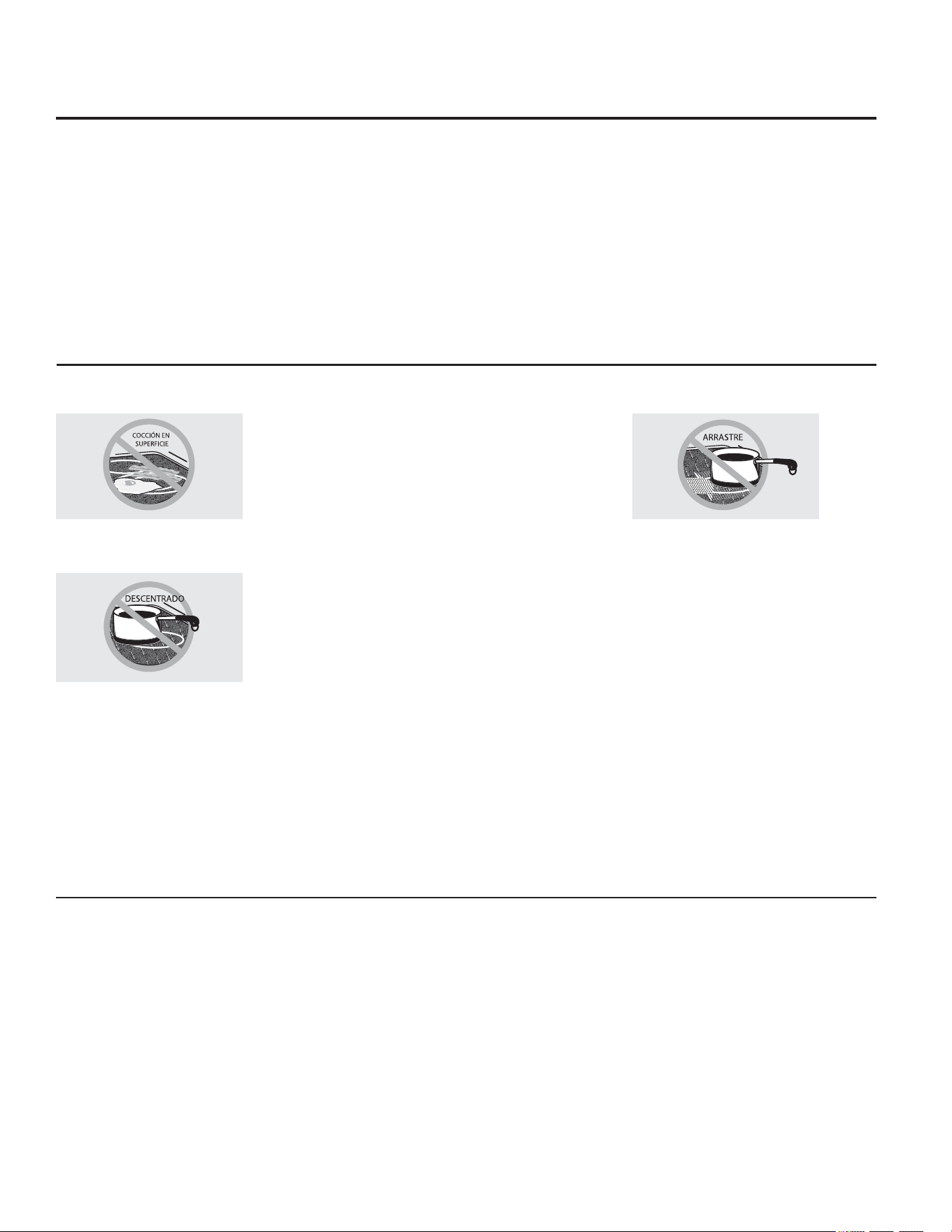
/LPLWDGRUGH7HPSHUDWXUDHQ(VWXIDVGH9LGULR5DGLDQWH
&DGDXQLGDGGHVXSHUILFLHUDGLDQWHFXHQWDFRQ
XQOLPLWDGRUGHWHPSHUDWXUD
(OOLPLWDGRUGHWHPSHUDWXUDHYLWDTXHODHVWXIDGH
YLGULRVHFDOLHQWHHQH[FHVR
(OOLPLWDGRUGHWHPSHUDWXUDSRGUiDSDJDUODV
XQLGDGHVVXSHUILFLDOHVSRUFLFORVGXUDQWHXQ
WLHPSRVL
ODROODKLHUYHKDVWDVHFDUVH
HOIRQGRGHODROODQRHVSODQR
ODROODHVWiIXHUDGHOFHQWUR
QRKD\ROODHQODXQLGDG
8VRGHXQLGDGHVGHODVXSHUILFLH
&RQVHMRVSDUD3URGXFWRV(QODWDGRVHQHO+RJDU
$VHJ~UHVHTXHHOSURGXFWRHQODWDGRVH
HQFXHQWUHVREUHODXQLGDGVXSHUILFLDO
$VHJ~UHVHGHTXHHOSURGXFWRHQODWDGRVHD
SODQRHQVXSDUWHLQIHULRU
3DUDHYLWDUTXHPDGRUDVGHYDSRURFDORU
WHQJDFXLGDGRDOHQODWDUHOSURGXFWR
8VHUHFHWDV\SURFHGLPLHQWRVGHIXHQWHV
FRQILDEOHV(VWRVVHHQFXHQWUDQGLVSRQLEOHVD
WUDYpVGHIDEULFDQWHVFRPR%DOO\.HUU\HO
'HSDUWPHQWRI$JULFXOWXUH([WHQVLRQ6HUYLFH
6HUYLFLRGHO'HSDUWDPHQWRGH$JULFXOWXUD
(OXVRGHHQODWDGRVFHUUDGRVDEDxRPDUtDFRQ
IRQGRVRQGHDGRVSRGUiQH[WHQGHUHOWLHPSR
UHTXHULGRSDUDWUDHUHODJXDDOSXQWRGHKHUYRU
3DUD0RGHORVFRQ(VWXIDGH9LGULR5DGLDQWH
/DHVWXIDUDGLDQWHFXHQWDFRQXQLGDGHV
FDOHQWDGRUDVGHEDMRGHXQDVXSHUILFLHOLVDGH
YLGULR
127$8QOLJHURRORUHVQRUPDOFXDQGR
XQDHVWXIDQXHYDVHXWLOL]DSRUSULPHUDYH]
(VSURYRFDGRSRUHOFDOHQWDPLHQWRGHSLH]DV
QXHYDV\PDWHULDOHVDLVODQWHV\GHVDSDUHFHUiHQ
SRFRWLHPSR
127$(QPRGHORVFRQHVWXIDVGHYLGULR
GHFRORUFODURHVQRUPDOTXHODV]RQDV
GHFRFFLyQFDPELHQGHFRORUFXDQGRHVWiQ
FDOLHQWHVRHQIULiQGRVH(VWRHVWHPSRUDO\
GHVDSDUHFHUiDPHGLGDTXHHOYLGULRVHHQIUtH
DWHPSHUDWXUDDPELHQWH
/DXQLGDGVXSHUILFLDOVHJXLUiXQFLFORGH
HQFHQGLGR\DSDJDGRSDUDPDQWHQHUVX
FRQILJXUDFLyQGHFRQWUROVHOHFFLRQDGD
(VVHJXURFRORFDUXWHQVLOLRVFDOLHQWHVHQOD
VXSHUILFLHGHYLGULRLQFOXVRFXDQGRODHVWXID
HVWpIUtD
$XQTXHODVXQLGDGHVGHVXSHUILFLHVHKD\DQ
DSDJDGRODHVWXIDGHYLGULRUHWLHQHVXILFLHQWH
FDORUSDUDFRQWLQXDUODFRFFLyQ3DUDHYLWDUOD
VREUHFRFFLyQTXLWHODVROODVGHODVXQLGDGHVGH
VXSHUILFLHFXDQGRORVDOLPHQWRVHVWpQFRFLGRV
1RFRORTXHQDGDVREUHODXQLGDGGHVXSHUILFLH
KDVWDTXHVHKD\DHQIULDGRSRUFRPSOHWR
/DVPDQFKDVGHDJXDGHSyVLWRVPLQHUDOHV
SXHGHQTXLWDUVHXWLOL]DQGRFUHPDOLPSLDGRUD
RYLQDJUHEODQFRVLQGLOXLU
(OXVRGHOLPSLDGRUGHYHQWDQDVSXHGHGHMDU
XQDSHOtFXODLULGLVFHQWHVREUHODHVWXID
/DFUHPDOLPSLDGRUDTXLWDUiHVWD
GHFRORUDFLyQ
1RDOPDFHQHHOHPHQWRVSHVDGRVVREUH
ODHVWXID6LFDHQVREUHODHVWXIDSRGUtDQ
SURYRFDUGDxRV
1RXWLOLFHODVXSHUILFLHFRPRXQDWDEODSDUD
FRUWDU
1XQFDFRFLQHGLUHFWDPHQWHVREUHHO
YLGULR6LHPSUHXWLOLFHUHFLSLHQWHVGH
FRFFLyQ
6LHPSUHFRORTXHHOUHFLSLHQWHHQHO
FHQWURGHODXQLGDGGHVXSHUILFLH
VREUHODTXHHVWiFRFLQDQGR
1RGHVOLFHORVUHFLSLHQWHVGHFRFFLyQDWUDYpVGHOFRQWURO
\ODVXSHUILFLHGHODHVWXIDSRUTXHSXHGHUD\DUHOYLGULR
(OYLGULRHVUHVLVWHQWHDORVUD\RQHVSHURQRDSUXHEDGH
ORVPLVPRV
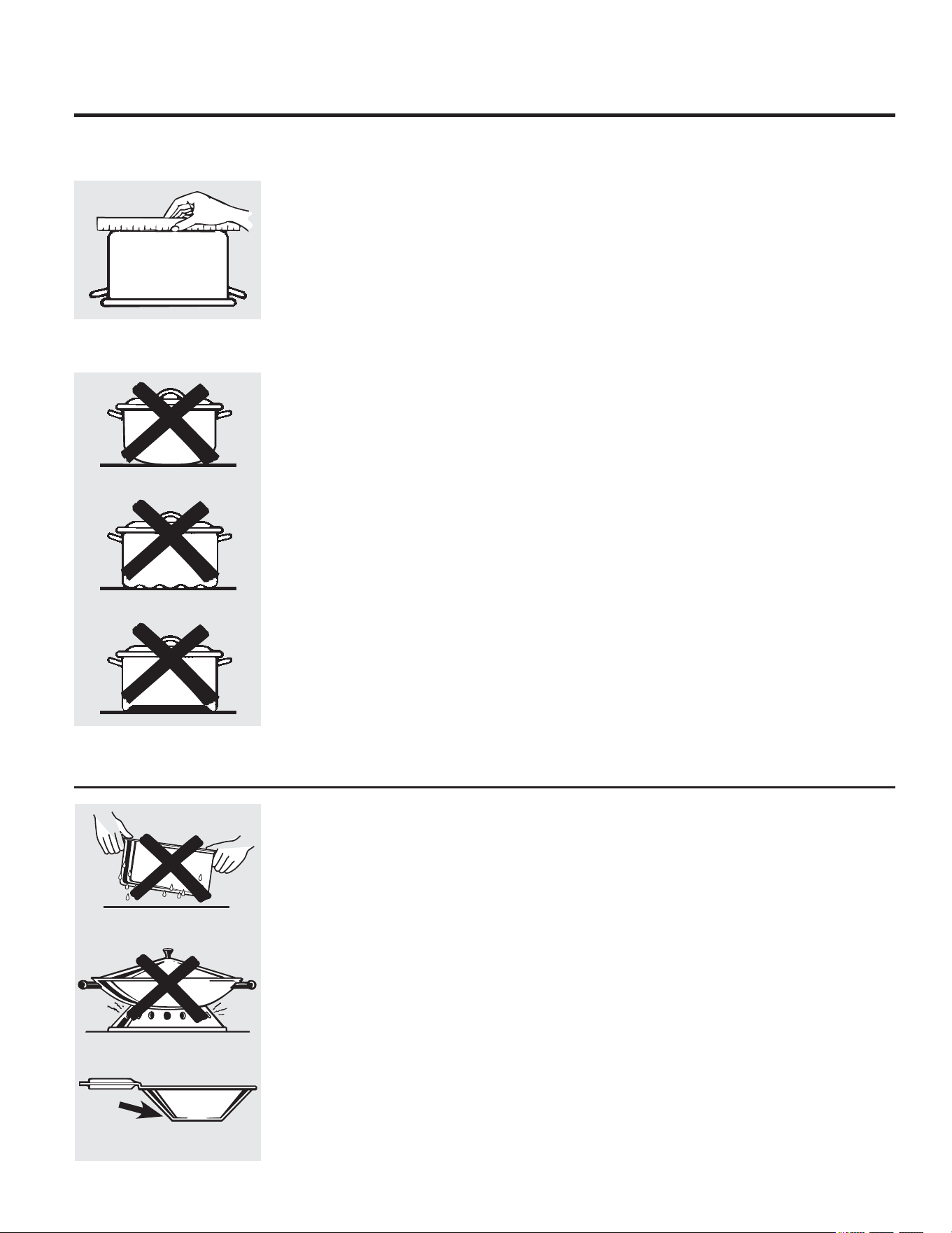
&yPRVHOHFFLRQDUWLSRVGHXWHQVLOLRVSDUD
PRGHORVGHHVWXIDGHYLGULRUDGLDQWH *($SSOLDQFHVFRP
$FHURLQR[LGDEOH
5HFRPHQGDGR
$OXPLQLR
6HUHFRPLHQGDGHFDSDJUXHVD
%XHQDFRQGXFWLYLGDG/RVUHVLGXRVGHDOXPLQLR
DYHFHVSDUHFHQUD\RQHVVREUHODHVWXIDSHUR
SXHGHQTXLWDUVHVLVHORVOLPSLDGHLQPHGLDWR
'HELGRDVXEDMRSXQWRGHIXVLyQQRGHEH
XWLOL]DUVHDOXPLQLRGHFDSDILQD
%DVHGHFREUH
5HFRPHQGDGR
(OFREUHSXHGHGHMDUUHVLGXRVTXHSXHGHQ
SDUHFHUUD\RQHV/RVUHVLGXRVSXHGHQ
HOLPLQDUVHVLHPSUH\FXDQGRODHVWXID
VHOLPSLHGHLQPHGLDWR6LQHPEDUJRQR
SHUPLWDTXHHVWDVROODVKLHUYDQHQVHFR
(OPHWDOVREUHFDOHQWDGRSXHGHDGKHULUVH
DODVHVWXIDVGHYLGULR6LQRVHHOLPLQDGH
LQPHGLDWRXQDROODFRQODEDVHGHFREUH
VREUHFDOHQWDGRGHMDUiXQUHVLGXRTXH
PDQFKDUiODHVWXIDHQIRUPDSHUPDQHQWH
(VPDOWHGHSRUFHODQDVREUHKLHUUR
IXQGLGR
6HUHFRPLHQGDVLODEDVHGHODROODVHHQFXHQWUD
UHYHVWLGD
(VPDOWHGHSRUFHODQDVREUHDFHUR
1RVHUHFRPLHQGD
&DOHQWDUUHFLSLHQWHVYDFtRVSXHGHSURYRFDU
GDxRVSHUPDQHQWHVDOYLGULRGHODVHVWXIDV(O
HVPDOWHSXHGHGHUUHWLUVH\DGKHULUVHDODHVWXID
FHUiPLFD
9LGULRFHUiPLFR
1RVHUHFRPLHQGD
'HVHPSHxRSREUH5D\DODVXSHUILFLH
&HUiPLFD
1RVHUHFRPLHQGD
'HVHPSHxRSREUH3XHGHUD\DUODVXSHUILFLH
+LHUURIXQGLGR
1RVHUHFRPLHQGDDPHQRVTXHVHHQFXHQWUH
HVSHFtILFDPHQWHGLVHxDGRSDUDHVWXIDVGHYLGULR
3REUHFRQGXFWLYLGDG\OHQWLWXGSDUDDEVRUEHUHO
FDORU5D\DODVXSHUILFLHGHODHVWXID
/DVLJXLHQWHLQIRUPDFLyQORD\XGDUiDHOHJLUORVUHFLSLHQWHVGHFRFFLyQTXHEULQGDQXQEXHQGHVHPSHxR
HQHVWXIDVGHYLGULR9HUHOIROOHWRVREUHUHFLSLHQWHVSDUDXVDUFRQHVWXIDVGHLQGXFFLyQ
127$6LJDWRGDVODVUHFRPHQGDFLRQHVGHOIDEULFDQWHGHUHFLSLHQWHVFXDQGRXWLOLFHFXDOTXLHUFODVH
GHUHFLSLHQWHGHFRFFLyQVREUHODHVWXIDFHUiPLFD
3DUDPHMRUHVUHVXOWDGRV
&RORTXHVyORUHFLSLHQWHVVHFRVVREUHORV
HOHPHQWRVGHVXSHUILFLH1RFRORTXHWDSDV
VREUHORVHOHPHQWRVGHVXSHUILFLHHQ
HVSHFLDOWDSDVPRMDGDV
1RXVHZRNVFRQDQLOORVGHVRSRUWH
(VWDFODVHGHZRNQRVHFDOLHQWDVREUH
HOHPHQWRVGHVXSHUILFLHGHYLGULR
5HFRPHQGDPRVHOXVRGHZRNVGH
EDVHSODQDVRODPHQWH6HHQFXHQWUDQ
GLVSRQLEOHVHQVXQHJRFLRPLQRULVWDORFDO
/DEDVHGHOZRNGHEHWHQHUHOPLVPR
GLiPHWURTXHHOHOHPHQWRGHVXSHUILFLH
SDUDDVHJXUDUXQFRQWDFWRDGHFXDGR
$OJXQRVSURFHGLPLHQWRVGHFRFFLyQ
HVSHFLDOHVUHTXLHUHQUHFLSLHQWHV
GHFRFFLyQHVSHFtILFRVFRPRROODV
DSUHVLyQIUHLGRUDVHWF7RGRVORV
UHFLSLHQWHVGHFRFFLyQGHEHQWHQHUEDVHV
SODQDV\VHUGHOWDPDxRFRUUHFWR
1RSHUPLWDTXHORVDOLPHQWRVKLHUYDQHQ
VHFR\DTXHORVUHFLSLHQWHVGHFRFFLyQ
SXHGHQDGKHULUVHDODVXSHUILFLHGH
FRFFLyQSURYRFDQGRGDxRVSHUPDQHQWHV
DODHVWXID
1RFRORTXHUHFLSLHQWHVPRMDGRV
VREUHODHVWXIDGHYLGULR
1RXVHZRNVFRQDQLOORVGH
VRSRUWHVREUHODHVWXIDGHYLGULR
8WLOLFHZRNVGHEDVHSODQDVREUH
ODHVWXIDGHYLGULR
9HULILTXHTXHORVUHFLSLHQWHV
WHQJDQEDVHVSODQDVXWLOL]DQGR
XQDUHJOD
1RVHUHFRPLHQGDQUHFLSLHQWHVFRQ
EDVHVUHGRQGHDGDVFXUYDGDVFRQ
UHERUGHVRWRUFHGXUDV
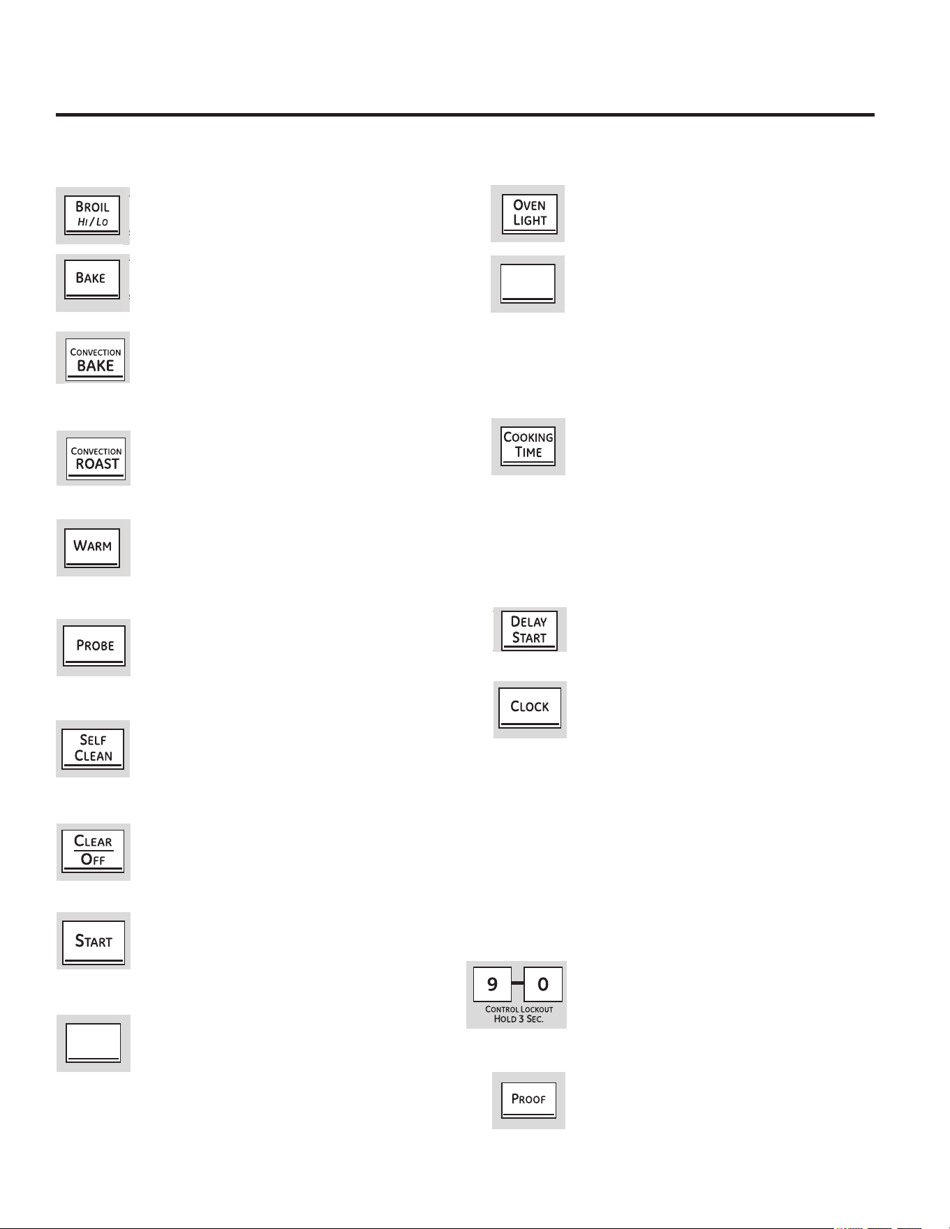
(VSRVLEOHTXHODVIXQFLRQHV\DSDULHQFLDVYDUtHQFRQUHODFLyQDVXPRGHORDORODUJRGHOPDQXDO
8VRGHORVFRQWUROHVGHOKRUQR
7HFOD$VDU$OWR%DMR
3UHVLRQHSDUDVHOHFFLRQDUODIXQFLyQDVDU/HD
ODVHFFLyQ&yPR&RQILJXUDUHO+RUQRSDUD$VDU
7HFODGH+RUQHDGR
3UHVLRQHSDUDVHOHFFLRQDUODIXQFLyQKRUQHDU
/HDODVHFFLyQ&yPR&RQILJXUDUHO+RUQRSDUD
+RUQHDU
7HFODGH+251($'2325&219(&&,Ï1
8VHXQYHQWLODGRUSDUDKDFHUFLUFXODUDLUHHQHO
KRUQR/HDODVHFFLyQVREUH8VRGHOKRUQRSRU
FRQYHFFLyQ
7HFODGH7RVWDGRSRU&RQYHFFLyQHQDOJXQRV
PRGHORV
7RXFKWRURDVWODUJHWHQGHUFXWVRIPHDW
6HHWKH8VLQJWKHFRQYHFWLRQRYHQVHFWLRQ
7HFOD:$50&DOHQWDU
3UHVLRQHSDUDPDQWHQHUFDOLHQWHVODVFRPLGDV
\DFRFLQDGDV/HDODVHFFLyQ&yPR&RQILJXUDUHO
+RUQRSDUD&DOHQWDU
7HFOD352%(6RQGD
3UHVLRQHDOXVDUODVRQGDSDUDFRFLQDUGHIRUPD
DXWRPiWLFDHQODWHPSHUDWXUDGHFRPLGDLQWHUQD
GHVHDGD&RQVXOWHODVHFFLyQ8VRGHOD6RQGD
7HFOD6(/)&/($1$XWR/LPSLH]D
3UHVLRQHODDXWROLPSLH]DGHOKRUQR&RQVXOWHOD
VHFFLyQ8VRGHO+RUQRFRQ$XWR/LPSLH]D
7HFODGH7LHPSRGH&RFFLyQ
3UHVLRQHSDUDFDQFHODU72'$6ODVRSHUDFLRQHV
GHOKRUQRH[FHSWRHOUHORM\HOWHPSRUL]DGRU
7HFODGH3UXHEDHQDOJXQRVPRGHORV
3UHVLRQHSDUDVHOHFFLRQDUXQDPELHQWHFiOLGR
TXHVHD~WLOSDUDODHOHYDFLyQGHSURGXFWRV
IHUPHQWDGRVDEDVHGHOHYDGXUD
7HFOD:$50,1*=21(ÈUHDSDUD&DOHQWDU
3UHVLRQHHVWDWHFODSDUDPDQWHQHUFDOLHQWHVODV
FRPLGDV\DFRFLQDGDV&RQVXOWHODVHFFLyQGH
8VRGHOÈUHDSDUD&DOHQWDU
7HFOD29(1/,*+7/X]GHO+RUQR
3UHVLRQHSDUDHQFHQGHURDSDJDUODVOXFHVGHO
KRUQR
7HFOD7,0(5212))(QFHQGHU$SDJDU
7HPSRUL]DGRU
127$$OFRQILJXUDUORVWLHPSRVVyORVHUHDOL]DQ
DMXVWHVGHKRUDV\PLQXWRV(OWLHPSRPtQLPRTXH
VHSXHGHFRQILJXUDUHVGHXQPLQXWR
3UHVLRQHSDUDFRQILJXUDUHOWHPSRUL]DGRU
GHODFRFLQD&RQVXOWHODVHFFLyQGH8VRGHO
7HPSRUL]DGRUGHOD&RFLQD
7HFOD&22.,1*7,0(7LHPSRGH&RFFLyQ
127$$OFRQILJXUDUORVWLHPSRVVyORVHUHDOL]DQ
DMXVWHVGHKRUDV\PLQXWRV(OWLHPSRPtQLPRTXH
VHSXHGHFRQILJXUDUHVGHXQPLQXWR
3UHVLRQHHVWDWHFOD\OXHJRSUHVLRQHODVWHFODV
QXPpULFDVSDUDFRQILJXUDUODFDQWLGDGGHWLHPSR
GXUDQWHHOFXDOGHVHHTXHVXFRPLGDVHFRFLQH(O
KRUQRVHDSDJDUiFXDQGRHOWLHPSRGHFRFFLyQ
VHKD\DWHUPLQDGR
/X]GHO+RUQR(QFHQGLGD$SDJDGD
7RXFKWKLVSDGWRVHWWKHRYHQWRVWDUW
DXWRPDWLFDOO\DWDWLPH\RXVHW
7HFOD%RUUDU$SDJDU
(OUHORMVHGHEHUiFRQILJXUDUHQODKRUDFRUUHFWD
GHOGtDSDUDTXHODVIXQFLRQHVDXWRPiWLFDVGHO
WHPSRUL]DGRUGHOKRUQRIXQFLRQHQGHIRUPD
DGHFXDGD/DKRUDGHOGtDQRVHSXHGHFDPELDU
GXUDQWHXQKRUQHDGRSRUWLHPSRRHOFLFORGH
OLPSLH]DDXWRPiWLFD
&RQVXOWHODVHFFLyQ3DUDFRQILJXUDUHOUHORM
6LVXKRUQRIXHFRQILJXUDGRSDUDXQ
IXQFLRQDPLHQWRSRUWLHPSR\VHSURGXFH
XQFRUWHGHFRUULHQWHHOUHORM\ODVIXQFLRQHV
SURJUDPDGDVVHUiQUHLQLFLDGDV/DKRUDGHOGtD
WLWLODUiHQODSDQWDOODFXDQGRKD\DKDELGRXQ
FRUWHGHFRUULHQWH
%/248(2'(/&21752/
/DVWHFODVGHFRQWUROVHSRGUiQEORTXHDUGH
PRGRTXHQRVHSXHGDQDFWLYDUVLVHSUHVLRQHV
&RQVXOWHODVHFFLyQ&yPR%ORTXHDUORV
&RQWUROHV
7HFOD3522)3UXHED
3UHVLRQHHVWDWHFODSDUDHOHYDUSURGXFWRV
IHUPHQWDGRVDEDVHGHOHYDGXUD&RQVXOWHOD
VHFFLyQ&yPR&RQILJXUDUHO+RUQRSDUD5HDOL]DU
3UXHEDV
KITCHEN
TIMER
ON/OFF
WARMING
ZONE
ON/OFF
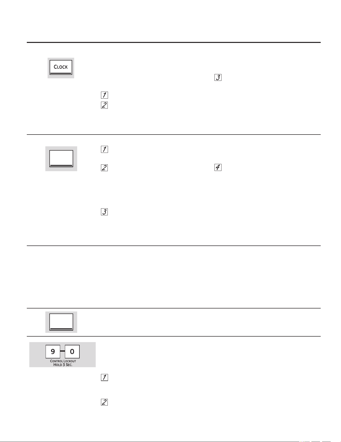
3DUD3URJUDPDUHO&RQWDGRUGH7LHPSR
3UHVLRQHODWHFOD.,7&+(17,0(5212))
7HPSRUL]DGRUGHOD&RFLQD(QFHQGLGR
$SDJDGR
3UHVLRQHODVWHFODVQXPpULFDVKDVWDTXHOD
FDQWLGDGGHWLHPSRTXHGHVHDDSDUH]FDHQ
ODSDQWDOOD3RUHMHPSORSDUDSURJUDPDU
KRUDV\PLQXWRVWRTXH\HQHVH
RUGHQ6LFRPHWHXQHUURUSUHVLRQHODWHFOD
.,7&+(17,0(5212))
7HPSRUL]DGRU
GHOD&RFLQD(QFHQGLGR$SDJDGR
\
YXHOYDDFRPHQ]DU
3UHVLRQHODWHFOD67$57,QLFLDU
/XHJRGHSUHVLRQDUODWHFOD67$57,QLFLDU6(7
&RQILJXUDFLyQGHVDSDUHFHHVWROHLQGLFDTXH
HOWLHPSRHVWiHQFXHQWDUHJUHVLYDDXQTXHOD
SDQWDOODQRFDPELDKDVWDTXHKD\DSDVDGRXQ
PLQXWR/RVVHJXQGRVQRVHPRVWUDUiQHQOD
SDQWDOODKDVWDTXHVHUHDOLFHODFXHQWDUHJUHVLYD
GHO~OWLPRPLQXWR
&XDQGRHOFRQWDGRUGHODFRFLQDOOHJXHD
HOFRQWUROKDUiSLWLGRVDJXGRVVHJXLGRVGH
XQSLWLGRDJXGRFDGDVHJXQGRVKDVWDTXH
VHSUHVLRQHODWHFOD
.,7&+(17,0(521
2))
7HPSRUL]DGRUGHOD&RFLQD
(QFHQGLGR$SDJDGR
(OWRQRGHVHJXQGRVVHSXHGHFDQFHODU
VLJXLHQGRORVSDVRVHQODVHFFLyQGHFRQWUROGH
IXQFLRQHV(VSHFLDOHVGHVXKRUQRHQ7RQHVDW
WKH(QGRID7LPHG&\FOH7RQRVDO)LQDOGHXQ
&LFORSRU7LHPSR
(O7HPSRUL]DGRUGHOD&RFLQDFXHQWD
HQKRUDV\PLQXWRV
(O7HPSRUL]DGRUGHOD&RFLQDQR
FRQWURODODVRSHUDFLRQHVGHOKRUQR/D
FRQILJXUDFLyQPi[LPDGHO7HPSRUL]DGRU
GHOD&RFLQDHVGHKRUDV\PLQXWRV
3DUD5HLQLFLDUHO7HPSRUL]DGRUGHOD&RFLQD
&yPR%ORTXHDUORV&RQWUROHV
3DUD&RQILJXUDUHO5HORM
6LODSDQWDOODD~QPXHVWUDHOWLHPSRUHVWDQWHOD
SXHGHFDPELDUSUHVLRQDQGRODWHFOD
.,7&+(1
7,0(5212))
7HPSRUL]DGRUGHOD&RFLQD
(QFHQGLGR$SDJDGR
\OXHJRSUHVLRQDQGRODV
WHFODVQXPpULFDVKDVWDTXHHOWLHPSRTXHGHVHD
DSDUH]FDHQODSDQWDOOD
6LHOWLHPSRUHVWDQWHQRVHHQFXHQWUDHQOD
SDQWDOODUHORMLQLFLRGHPRUDGRRWLHPSRGH
FRFFLyQDSDUHFHQHQODSDQWDOODUHFXHUGHHO
WLHPSRUHVWDQWHSUHVLRQDQGRODWHFOD
.,7&+(1
7,0(5212))
7HPSRUL]DGRUGHOD&RFLQD
(QFHQGLGR$SDJDGR
\OXHJRSUHVLRQDQGRODV
WHFODVQXPpULFDVSDUDLQJUHVDUHOQXHYRWLHPSR
TXHGHVHH
&RQWURO/RFNRXW%ORTXHRGHO&RQWUROOH
SHUPLWLUiEORTXHDUODVWHFODVWiFWLOHVGHPRGR
TXHQRVHSXHGDQDFWLYDUDOVHUWRFDGDV
3DUD
EORTXHDUGHVEORTXHDUORVFRQWUROHV
0DQWHQJDSUHVLRQDGDVODVWHFODV\DO
PLVPRWLHPSRGXUDQWHVHJXQGRV/D
SDQWDOODPRVWUDUi/2&21%ORTXHR
(QFHQGLGR
3DUDGHVEORTXHDUHOFRQWUROPDQWHQJD
SUHVLRQDGDVODVWHFODV\DOPLVPR
WLHPSRGXUDQWHVHJXQGRV/DSDQWDOOD
PRVWUDUi/2&2))%ORTXHR$SDJDGR
&XDQGRHVWDIXQFLyQHVWpHQFHQGLGDODVWHFODV
WiFWLOHVQRUHVSRQGHUiQH[FHSWRODWHFOD&OHDU
2II%RUUDU$SDJDU
/RVDMXVWHVVHJXDUGDUiQHQODPHPRULD
OXHJRGHXQFRUWHGHFRUULHQWH
(OUHORMVHGHEHUiFRQILJXUDUHQODKRUD
FRUUHFWDGHOGtDSDUDTXHODVIXQFLRQHV'HOD\
6WDUW,QLFLR'HPRUDGRIXQFLRQHQGHIRUPD
DGHFXDGD/DKRUDGHOGtDQRVHSXHGHFDPELDU
GXUDQWHXQDFRFFLyQGHPRUDGDRGXUDQWHHO
FLFORGHDXWROLPSLH]D
3UHVLRQHODWHFOD&ORFN5HORM
3UHVLRQHODVWHFODVQXPpULFDVKDVWDTXHOD
KRUDFRUUHFWDGHOGtDDSDUH]FDHQOD
SDQWDOOD6LODVWHFODVQXPpULFDVQRVH
WRFDQGHQWURGHXQPLQXWROXHJRGHKDEHU
WRFDGRODWHFOD&/2&.5HORMODSDQWDOOD
YXHOYHDODFRQILJXUDFLyQRULJLQDO6LHVWR
VXFHGHSUHVLRQHODWHFOD&/2&.5HORM\
YXHOYDDLQJUHVDUODKRUDGHOGtD
3UHVLRQHODWHFOD6WDUW,QLFLDUKDVWDTXHOD
KRUDGHOGtDDSDUH]FDHQODSDQWDOOD(VWR
LQJUHVDODKRUDHLQLFLDHOUHORM
3DUDFRQWURODUODKRUDGHOGtDFXDQGR
ODSDQWDOODPXHVWUDRWUDLQIRUPDFLyQ
VLPSOHPHQWHSUHVLRQHODWHFOD&/2&.5HORM
/DKRUDGHOGtDDSDUHFHKDVWDTXHRWUDWHFOD
HVSUHVLRQDGD3DUDFDPELDUHOIRUPDWRGHOD
KRUDRDSDJDUODSDQWDOODGHOUHORMFRQVXOWHOD
VHFFLyQ6SHFLDO)HDWXUHV)XQFLRQHV(VSHFLDOHV
3DUD&DQFHODUHO7HPSRUL]DGRUGHOD&RFLQD
7RXFKWKH.,7&+(17,0(5212))SDGWZLFH
8VRGHOUHORMWHPSRUL]DGRUGHODFRFLQD
\EORTXHRGHOFRQWURO *($SSOLDQFHVFRP
KITCHEN
TIMER
ON/OFF
KITCHEN
TIMER
ON/OFF
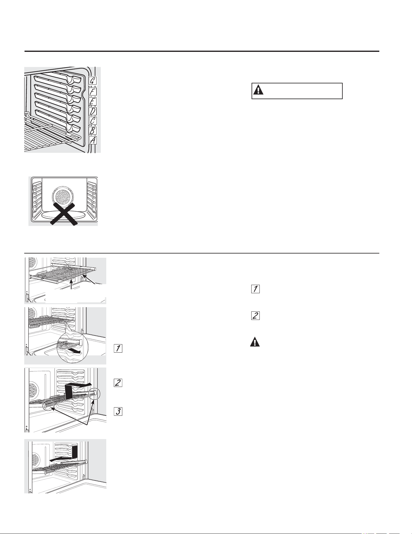
*UDVSKHUH
&yPRXVDUHOKRUQR
3DUDHYLWDUSRVLEOHVTXHPDGXUDVFRORTXHODVEDQGHMDVHQODSRVLFLyQGHVHDGDDQWHVGHHQFHQGHUHOKRUQR
/DVEDQGHMDVWLHQHQWRSHVGHPRGRTXH
FXDQGRVHODVFRORFDFRUUHFWDPHQWHHQORV
VRSRUWHVVHGHWHQGUiQDQWHVGHVDOLUVHGHOWRGR
\QRVHYROFDUiQ
&XDQGRFRORTXHRTXLWHUHFLSLHQWHVGHFRFFLyQ
WLUHGHODEDQGHMDKDVWDTXHVHGHWHQJD
(QDOJXQRVPRGHORVHOHOHPHQWRFDOHQWDGRU
SDUDKRUQHDGRVHHQFXHQWUDGHEDMRGHOSLVRGHO
KRUQR1XQFDFRORTXHXWHQVLOLRVGHFRFLQD
SLHGUDVSDUDSL]]DQLRWURVDUWtFXORVHQHO
SLVRGHOKRUQR
3DUDTXLWDUXQDEDQGHMDWLUHGHHOODLQFOLQHHO
H[WUHPRIURQWDOKDFLDDUULED\ViTXHOD
3DUDYROYHUDFRORFDUODGHSRVLWHHOH[WUHPR
GHODEDQGHMDWRSHVGHGHWHQFLyQVREUHHO
VRSRUWHLQFOLQHHOIUHQWHKDFLDDUULED\SUHVLRQH
ODEDQGHMDKDFLDDGHQWUR
&XDQGRXWLOLFHODEDQGHMDHQODSRVLFLyQPiV
EDMD$QHFHVLWDUiWHQHUFXLGDGRFXDQGROD
TXLWH5HFRPHQGDPRVTXHGHVOLFHODEDQGHMD
YDULDVSXOJDGDV\OXHJRXWLOL]DQGRGRV
DJDUUDGHUDVODTXLWHVRVWHQLHQGRGHDPERV
ODGRV/DEDQGHMDVHHQFXHQWUDPX\DEDMR\
XVWHGSXHGHTXHPDUVHVLFRORFDODPDQRHQOD
PLWDGGHODEDQGHMD\WLUDKDFLDDIXHUD7HQJD
PXFKRFXLGDGRGHQRTXHPDUVHODPDQRFRQOD
SXHUWDFXDQGRXWLOLFHODEDQGHMDHQODSRVLFLyQ
PiVEDMD$
/DFDQWLGDGGHSRVLFLRQHV
GHODEDQGHMDSXHGHYDULDUHQ
UHODFLyQDOPRGHOR
35(&$8&,Ï1
3DUULOODGHH[WHQVLyQHQDOJXQRVPRGHORV
&XDQGRFRORTXHRTXLWHUHFLSLHQWHV
GHFRFFLyQVLHPSUHWLUHGHODSDUULOODKDFLD
DIXHUDGHVGHHOULHOIURQWDOVXSHULRUKDVWD
DOFDQ]DUODSRVLFLyQGHDSHUWXUDWRWDO
1RH[WLHQGDODSDUULOODUiSLGDPHQWH/RV
DOLPHQWRVSXHGHQGHVOL]DUVHGHVGHHOIUHQWH
GHODSDUULOOD
3DUDTXLWDUODSDUULOOD
$VHJ~UHVHGHLQWURGXFLUODSDUULOODKDVWDHO
IRQGRGHOKRUQRGHPRGRTXHODVSDOHWDV
ODWHUDOHVGHODUPD]yQGHODSDUULOODVH
GHVHQJDQFKHQGHODFDYLGDG
'HVOLFHODSDUULOODKDFLDXVWHGKDVWDTXH
OOHJXHDOWRSHSRVLFLyQGHWHQLGDGHO
VRSRUWHGHODSDUULOOD
,QFOLQHHOH[WUHPRIURQWDOKDFLDDUULED\
TXtWHOR
127$&XDQGRPDQLSXOHODSDUULOODGH
H[WHQVLyQQRSHUPLWDTXHODSRUFLyQ
GHVOL]DEOHVHDEUD(VWRSXHGHGDxDUORV
GHVOL]DGRUHV
3DUDYROYHUDFRORFDUODSDUULOOD
7RPHILUPHPHQWHDPERVODGRVGHO
DUPD]yQGHODSDUULOOD\ODSDUULOOD
GHVOL]DEOH
&RORTXHHOH[WUHPRFXUYRGHOHVWDQWHHQOD
SRVLFLyQGHVHDGDLQFOLQHHOIUHQWHKDFLD
DUULED\SUHVLRQHODSDUULOODKDFLDDGHQWUR
35(&$8&,Ï1
1XQFDXWLOLFHODSDUULOODFXDQGRVXDUPD]yQ
QRVHHQFXHQWUDFRPSOHWDPHQWHLQWURGXFLGR
HQHOKRUQR\WUDEDGRHQVXSRVLFLyQ
&XDQGRODSDUULOODVHHQFXHQWUDELHQLQVWDODGD
\WUDEDGDHQVXOXJDUODVSDOHWDVODWHUDOHVGH
EORTXHRGHODUPD]yQGHODSDUULOODVHWUDEDUiQ
HQVXOXJDUHQORVVRSRUWHVGHOKRUQR6L
ODVSDOHWDVODWHUDOHVQRVHWUDEDURQHQVX
SRVLFLyQUHSLWDORVSDVRVDQWHULRUHV\YHULILTXH
TXHODVSDOHWDVODWHUDOHVVHKD\DQOLPSLDGR
\OXEULFDGRFRUUHFWDPHQWH9HU3DUULOODGH
H[WHQVLyQHQODVHFFLyQ&XLGDGR\OLPSLH]D
5LHOIURQWDO
VXSHULRU
3RVLFLyQGH
DSHUWXUDWRWDO
1XQFDFRORTXHXWHQVLOLRVGH
FRFLQDSLHGUDVSDUDSL]]DQLRWURV
DUWtFXORVHQHOSLVRGHOKRUQR
$QWHVGHFRPHQ]DU«
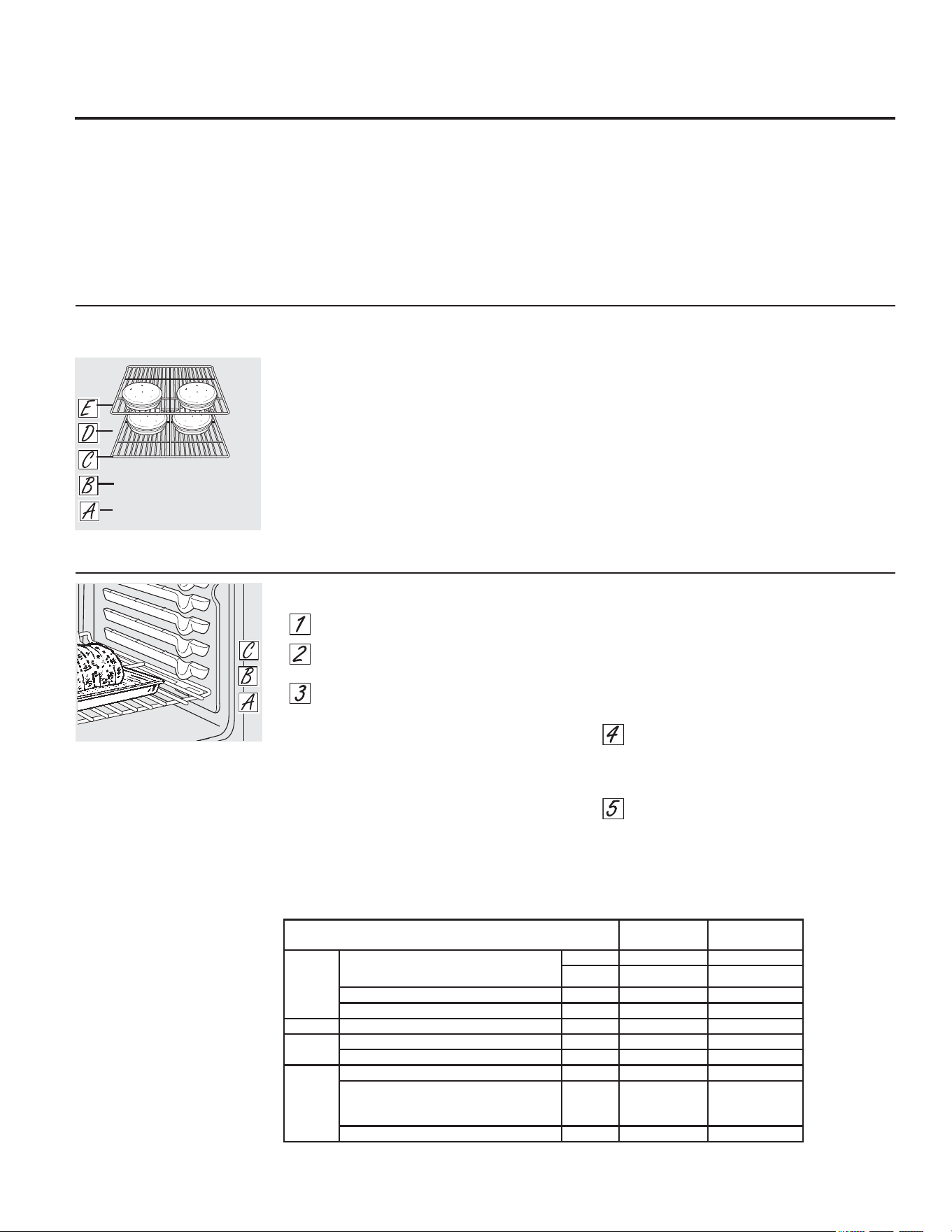
&yPRFRQILJXUDUHOKRUQRSDUDKRUQHDGRRURVWL]DGR
3UHVLRQHHOERWyQ%$.(KRUQHDU
3UHVLRQHODVDOPRKDGLOODVQXPpULFDVKDVWD
TXHDSDUH]FDODWHPSHUDWXUDGHVHDGD
3UHVLRQHHOERWyQ67$57LQLFLDU
(OKRUQRVHLQLFLDUiDXWRPiWLFDPHQWH/D
SDQWDOODPRVWUDUi3U(PLHQWUDVUHDOL]DHO
SUHFDOHQWDPLHQWR&XDQGRHOKRUQRDOFDQ]DOD
WHPSHUDWXUDVHOHFFLRQDGDHOFRQWUROGHOKRUQR
HPLWLUiYDULRVSLWLGRV\ODSDQWDOODPRVWUDUiOD
WHPSHUDWXUDGHOKRUQR
127$ 8VWHGHVFXFKDUiHOYHQWLODGRU
GHFRQYHFFLyQHQDOJXQRVPRGHORVPLHQWUDVHO
KRUQRUHDOL]DHOSUHFDOHQWDPLHQWR
(OYHQWLODGRUVHGHWHQGUiFXDQGRHOKRUQRVH
KD\DSUHFDOHQWDGR\ODSDQWDOODPRVWUDUiOD
WHPSHUDWXUDFRQILJXUDGD(VWRHVQRUPDO
3DUDFDPELDUODWHPSHUDWXUDGHOKRUQRGXUDQWHHO
FLFOR%$.(KRUQHDUSUHVLRQHHOERWyQ%$.(
\OXHJRODVDOPRKDGLOODVQXPpULFDVSDUDFRQILJXUDU
ODQXHYDWHPSHUDWXUD
9HULILTXHHOQLYHOGHFRFFLyQGHORVDOLPHQWRV
FXDQGRKD\DDOFDQ]DGRHOWLHPSRPtQLPR
LQGLFDGRHQODUHFHWD&RFtQHORVPiVVLIXHVH
QHFHVDULR
3UHVLRQHHOERWyQ&/($52))ERUUDU
DSDJDGRFXDQGRVHKD\DILQDOL]DGRHO
KRUQHDGR\OXHJRTXLWHORVDOLPHQWRVGHO
KRUQR
3UHFDOHQWDPLHQWR\FRORFDFLyQGHUHFLSLHQWH
3DUDHYLWDUSRVLEOHVTXHPDGXUDVFRORTXH
ODVEDQGHMDVHQODSRVLFLyQGHVHDGDDQWHVGH
HQFHQGHUHOKRUQR
3UHFDOLHQWHGHOKRUQRVLDVtORLQGLFDODUHFHWD
(OSUHFDOHQWDPLHQWRHVQHFHVDULRSDUDREWHQHU
EXHQRVUHVXOWDGRVFXDQGRKRUQHHSDVWHOHV
JDOOHWDVSDVWHOLWRV\SDQHV
6LYDDKRUQHDUFXDWURFDSDVGHSDVWHODOPLVPR
WLHPSRFRORTXHGRVFDSDVHQODEDQGHMD&\GRV
FDSDVHQODEDQGHMD('LVWULEX\DORVUHFLSLHQWHV
GHPRGRTXHQRTXHGHQGLUHFWDPHQWHXQR
HQFLPDGHORWUR
/RVUHVXOWDGRVGHKRUQHDGRVHUiQPHMRUHVVL
ORVDOLPHQWRVVHFHQWUDQELHQGHQWURGHOKRUQR
(OSDVWHO´$QJHOIRRGµHVODH[FHSFLyQ\GHEH
FRORFDUVHHQODEDQGHMDLQIHULRUGHOKRUQRSRVLFLyQ
$6LJDODVLQVWUXFFLRQHVGHOSDTXHWHGHDOLPHQWRV
SUHHPSDTXHWDGRVRFRQJHODGRVSDUDODXELFDFLyQ
GHORVUHFLSLHQWHV/RVUHFLSLHQWHVQRGHEHQWRFDUVH
HQWUHVtRWRFDUODVSDUHGHVGHOKRUQR6LQHFHVLWD
XWLOL]DUGRVEDQGHMDVGLVWULEX\DORVUHFLSLHQWHVGH
PRGRTXHQRTXHGHQGLUHFWDPHQWHXQRHQFLPD
GHORWUR'HMHDSUR[LPDGDPHQWH
øsFPHQWUH
UHFLSLHQWHV\GHVGHHOIUHQWHSDUWHWUDVHUD\ODGRVGH
ODVSDUHGHVGHOKRUQR
*($SSOLDQFHVFRP
3DSHOGHDOXPLQLR
1RXVHSDSHOGHDOXPLQLRSDUDFXEULUHOIRQGR
GHOKRUQR(ODOXPLQLRDWUDSDUiHOFDORUHQOD
SDUWHLQIHULRU\DOWHUDUiHOIXQFLRQDPLHQWRGHO
KRUQR(ODOXPLQLRVHSXHGHGHUUHWLU\GDxDU
GHIRUPDSHUPDQHQWHHOIRQGRGHOKRUQR
&XDOTXLHUGDxRSRUXVRLQDGHFXDGRGHO
DOXPLQLRQRHVWDUiFXELHUWRSRUODJDUDQWtDGHO
SURGXFWR
(ODOXPLQLRVHSXHGHXVDUSDUDUHWHQHUGHUUDPHV
FRORFDQGRXQDKRMDHQHOHVWDQWHLQIHULRUYDULDV
SXOJDGDVSRUGHEDMRGHODFRPLGD1RXVH
PiVDOXPLQLRTXHHOQHFHVDULR\QXQFDFXEUD
WRWDOPHQWHXQHVWDQWHGHOKRUQRFRQSDSHOGH
DOXPLQLR0DQWHQJDHODOXPLQLRSRUORPHQRVD
XQDSXOJDGD\PHGLDGHODVSDUHGHVGHOKRUQR
SDUDHYLWDUXQDPDODFLUFXODFLyQGHOFDORU
*XtDSDUD'RUDU
&DUQHV
7HPSHUDWXUD
GHO+RUQR
7HPSHUDWXUD
,QWHULRU
%LIH $VDGRGH&RVWLOODDOE
'HVKXHVDGD\&RQ+XHVRV
-XJRVR Û) Û)
$3XQWR Û) Û)
%LIHGH/RPRDOE -XJRVR Û) Û)
%LIHGH/RPRDOE -XJRVR Û) Û)
&HUGR &RQ+XHVRV'HVKXHVDGDD/EV Û) Û)
&RUGHUR &RQ+XHVRVD/EV $3XQWR Û) Û)
'HVKXHVDGDDOE $3XQWR Û) Û)
$YH 3ROOR(QWHURDOE Û) Û)
3DYR(QWHUR
6LQ5HOOHQRDOE
6LQ5HOOHQRDOE
Û)
Û)
Û)
Û)
3HFKXJDGH3DYRDOE Û) Û)
/DVDYHVFRQSOXPDVJHQHUDOPHQWHUHTXLHUHQGHXQWLHPSRGHDVDGRDGLFLRQDOGHDPLQXWRV&XEUD
ODVSDWDV\ODSHFKXJDFRQSDSHOGHDOXPLQLRSDUDHYLWDUXQGRUDGRH[FHVLYR\TXHVHVHTXHODSLHO
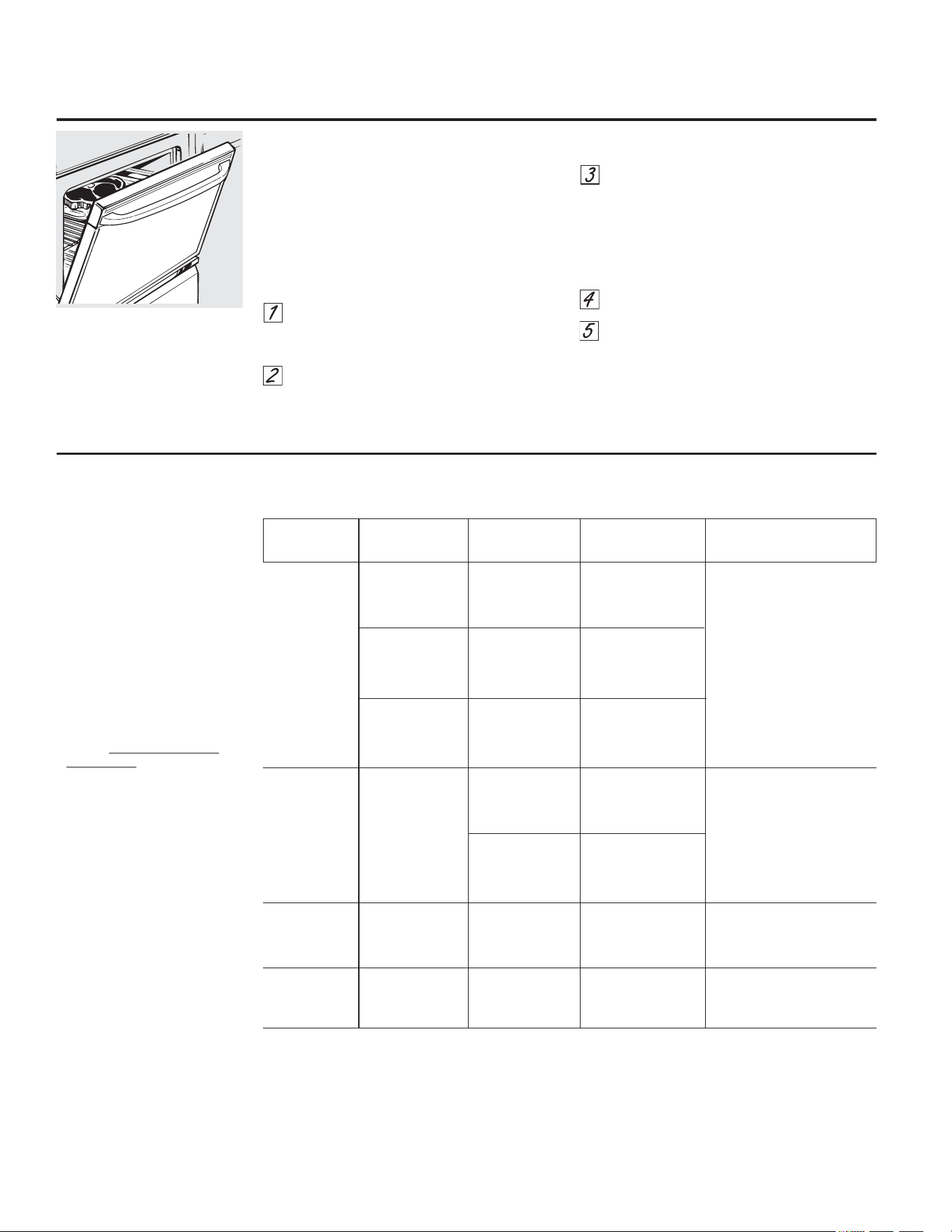
&yPRXVDUHOKRUQR
&yPRFRQILJXUDUHOKRUQRSDUDDVDU
6LVXFRFLQDHVWiFRQHFWDGDDYROWLRV
SXHGHQDVDUVHILOHWHVMXJRVRVSUHFDOHQWDQGRHO
DVDGRU\FRORFDQGRODEDQGHMDGHOKRUQRHQ
XQDSRVLFLyQPiVHOHYDGD
8WLOLFH/2%URLODVDUEDMRSDUDFRFLQDUSRU
FRPSOHWRDOLPHQWRVFRPRDYHVRFRUWHV
JUXHVRVGHFDUQHVLQGRUDUORVGHPiV
&RORTXHODFDUQHRSHVFDGRVREUHXQD
DVDGHUDGHQWURGHXQDUHMLOODGLVHxDGD
SDUDDVDU
6LJDODVSRVLFLRQHVGHODVEDQGHMDV
VXJHULGDVHQOD*XtDGHDVDGR
3UHVLRQHHOERWyQ%52,/+,/2DVDUDOWR
EDMRXQDYH]SDUDFRQILJXUDU+,%URLO
DVDUDOWR
3DUDFDPELDUD/2%URLODVDUEDMR
SUHVLRQHHOERWyQ%52,/+,/2DVDUDOWR
EDMRGHQXHYR
3UHVLRQHHOERWyQ67$57LQLFLDU
&XDQGRKD\DILQDOL]DGRGHDVDUSUHVLRQH
HOERWyQ&/($52))ERUUDUDSDJDGR
(OWDPDxRSHVRJURVRU
WHPSHUDWXUDLQLFLDO\
HOSXQWRGHFRFFLyQSUHIHULGR
DIHFWDUiQORVWLHPSRV
GHDVDGR(VWDJXtDHVWi
EDVDGDHQFDUQHVD
WHPSHUDWXUDGHUHIULJHUDGRU
(O0LQLVWHULRGH$JULFXOWXUDGH
ORV((88DILUPD´ODFDUQHGH
UHVMXJRVDHVSRSXODUSHURGHEH
VDEHUVHTXHDOFRFLQDUODDVyOR
)&DOJXQRVRUJDQLVPRV
TXHSURYRFDQLQWR[LFDFLyQ
DOLPHQWDULDSXHGHQVREUHYLYLUµ
)XHQWH6DIH)RRG%RRN<RXU
.LWFKHQ*XLGH86'$5HY
-XQLR
*XtDGHDVDGR
1LYHO 3RVLFLyQ
$OLPHQWR GHFRFFLyQ 7LSRRJURVRU GHODEDQGHMD &RPHQWDULRV
&DUQHGHUHV -XJRVD )LOHWHV² (R)ORVDOLPHQWRV (VGLItFLOFRFLQDUILOHWHVGHPHQRV
)& *URVRUGHµFP GHEHQHVWDUµDµ GHODµFPGHJURVRU\TXH
>FPDFP@GHO TXHGHQMXJRVRV6HFRFLQDQ
HOHPHQWRGHDVDGR SRUFRPSOHWRDQWHVGHGRUDUVH
FRFLQDQSRUFRPSOHWR
$SXQWR )LOHWHV² (ORVDOLPHQWRVGHEHQ 3DUDHYLWDUTXHODFDUQD
)& µDµFPD HVWDUGHµDµ VHHQURVTXHFRUWHODJUDVDDVH
FPGHJURVRU >FPDFP@GHO HQURVTXHLQWHUYDORVGHµFP
HOHPHQWRGHDVDGR
%LHQFRFLGD )LOHWHV² 'R(ORVDOLPHQWRV
)& µDµFPD GHEHQHVWDUGHµDµ
FPGHJURVRUR >FPDFP@GHO
SDWWLHVGHFDUQHSLFDGD HOHPHQWRGHDVDGR
3ROOR 3HFKXJDVLQKXHVR &ORVDOLPHQWRVGHEHQ $VDUVREUHHOODGRGHODSLHO
HVWDUGHµDµ SULPHUR
>FPDFP@GHO
HOHPHQWRGHDVDGR
3HFKXJDFRQKXHVR &ORVDOLPHQWRVGHEHQ
HVWDUGHµDµ
>FPDFP@GHO
HOHPHQWRGHDVDGR
)LOHWHVGH µDµFPD 'R(ORVDOLPHQWRV 0DQLSXOH\JLUHFRQ
SHVFDGR FPGHJURVRU GHEHQHVWDUµDµ PXFKRFXLGDGR
>FPDFP@GHO
HOHPHQWRGHDVDGR
&KXOHWDV %LHQFRFLGD µFP 'ORVDOLPHQWRVGHEHQ 3DUDHYLWDUTXHODFDUQDGHFHUGR
)& GHJURVRU HVWDUGHµDµ VHHQURVTXHFRUWH
>FPDFP@GHO ODJUDVDDLQWHUYDORV
HOHPHQWRGHDVDGR GHµFP
'HMHODSXHUWDDELHUWDHQODSRVLFLyQ
GHGHWHQFLyQGHDVDGR/DSXHUWD
TXHGDDELHUWD\D~QDVtVH
PDQWLHQHODWHPSHUDWXUDDGHFXDGD
HQHOKRUQR
3UHFDOLHQWHODDVDGHUDGXUDQWHPLQXWRVSDUDPHMRUDUHOGHVHPSHxR
6LVXFRFLQDHVWiFRQHFWDGDDYROWLRVORVELVWHFVYXHOWD\YXHOWDVHSXHGHQDVDU
SUHFDOHQWDQGRHODVDGRU\SRVLFLRQDQGRHOHVWDQWHGHOKRUQRXQDSRVLFLyQPiVDUULED
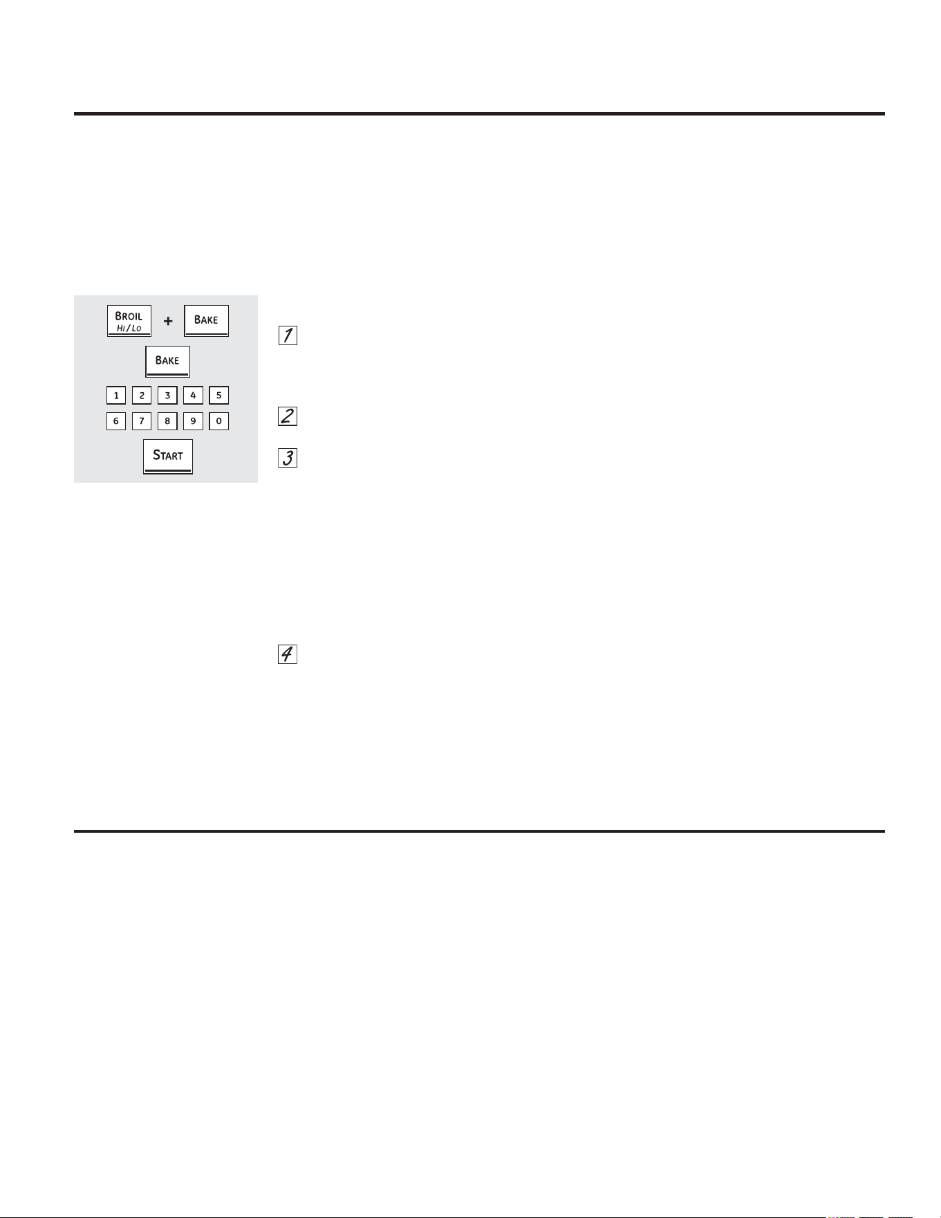
&yPRDMXVWDUHOWHUPRVWDWR
3UHVLRQHORVERWRQHV%52,/+,/2DVDU
DOWREDMR\%$.(KRUQHDUDOPLVPR
WLHPSRKDVWDTXHHQODSDQWDOODSXHGD
YHUVH6)
3UHVLRQHODWHFOD%$.(+RUQHDU(QOD
SDQWDOODVHPXHVWUDXQQ~PHUR
/DWHPSHUDWXUDGHOKRUQRSXHGHVXELUVH
HQ)&REDMDUVHHQ)
&3UHVLRQHODVDOPRKDGLOODVQXPpULFDV
GHODPLVPDPDQHUDHQTXHODVOHH3RU
HMHPSORSDUDFDPELDUODWHPSHUDWXUDGHO
KRUQR)&SUHVLRQH\
3UHVLRQHODWHFOD%$.(+RUQHDU
QXHYDPHQWHSDUDDOWHUQDUHQWUH
LQFUHPHQWDU\UHGXFLUODWHPSHUDWXUDGHO
KRUQR
&XDQGRKD\DILQDOL]DGRHODMXVWHSUHVLRQH
HOERWyQ67$57LQLFLDUSDUDYROYHUDOD
SDQWDOODGHODKRUD8WLOLFHHOKRUQRGHOD
PDQHUDQRUPDO
£$MXVWHHOWHUPRVWDWRGHOKRUQRXVWHGPLVPR *($SSOLDQFHVFRP
(VSRVLEOHTXHVXQXHYRKRUQRFRFLQHGHPDQHUDGLIHUHQWHDODTXHXVWHGVHHQFXHQWUDDFRVWXPEUDGR8WLOtFHORGXUDQWH
DOJXQDVVHPDQDVSDUDIDPLOLDUL]DUVHFRQVXVIXQFLRQHV6LOXHJRGHHVWHSHUtRGRFRQVLGHUDTXHODWHPSHUDWXUDGHOKRUQR
HVGHPDVLDGREDMDRGHPDVLDGRDOWDXVWHGSXHGHUHJXODUHOWHUPRVWDWR
1RXWLOLFHWHUPyPHWURVFRPRORVTXHVHYHQGHQHQODVWLHQGDVSDUDYHULILFDUODFRQILJXUDFLyQGHWHPSHUDWXUDGHOKRUQR
(VRVWHUPyPHWURVSXHGHQYDULDUHQWUH²JUDGRV
127$(VWHDMXVWHVyORDIHFWDODVWHPSHUDWXUDVGHKRUQHDGR\URVWL]DGRQRDIHFWDODVWHPSHUDWXUDVGHDVDGRR
GHDXWROLPSLH]D(ODMXVWHVHFRQVHUYDUiHQODPHPRULDD~QGHVSXpVGHXQFRUWHGHHQHUJtD
£(OWLSRGHPDUJDULQDXWLOL]DGRPRGLILFDHOKRUQHDGR
/DPD\RUtDGHODVUHFHWDVGHKRUQHDGRLQFOX\HQSURGXFWRVGHDOWRFRQWHQLGRJUDVRWDOHVFRPRODPDQWHFDRODPDUJDULQD
GHJUDVD6LVHUHGXFHHOFRQWHQLGRGHJUDVDHOUHVXOWDGRILQDOSXHGHVHUGLIHUHQWHDOHVSHUDGR
6LVHXWLOL]DQSURGXFWRVGHEDMRFRQWHQLGRJUDVRHQWRUWDVSDVWHOHVPDVDVJDOOHWDVRGXOFHVODUHFHWDSXHGHIUDFDVDU$
PHQRUFRQWHQLGRJUDVRPD\RUHVGLIHUHQFLDVHQHOUHVXOWDGRILQDO
/DVQRUPDVIHGHUDOHVH[LJHQTXHORVSURGXFWRVFRQGHQRPLQDFLyQGH´PDUJDULQDµWHQJDQXQFRQWHQLGRJUDVRGHDOPHQRV
HQUHODFLyQDOSHVR/RVSURGXFWRVGHEDMRFRQWHQLGRJUDVRFRQWLHQHQPHQRVJUDVD\PiVDJXD(OHOHYDGRFRQWHQLGRGHKXPHGDG
GHHVWRVSURGXFWRVDIHFWDODWH[WXUD\HOVDERUGHORVDOLPHQWRVKRUQHDGRV3DUDREWHQHUORVPHMRUHVUHVXOWDGRVFRQVXVUHFHWDV
WUDGLFLRQDOHVIDYRULWDVXWLOLFHPDUJDULQDXRWURVSURGXFWRVFRQXQFRQWHQLGRGHSRUORPHQRVGHDFHLWHYHJHWDO
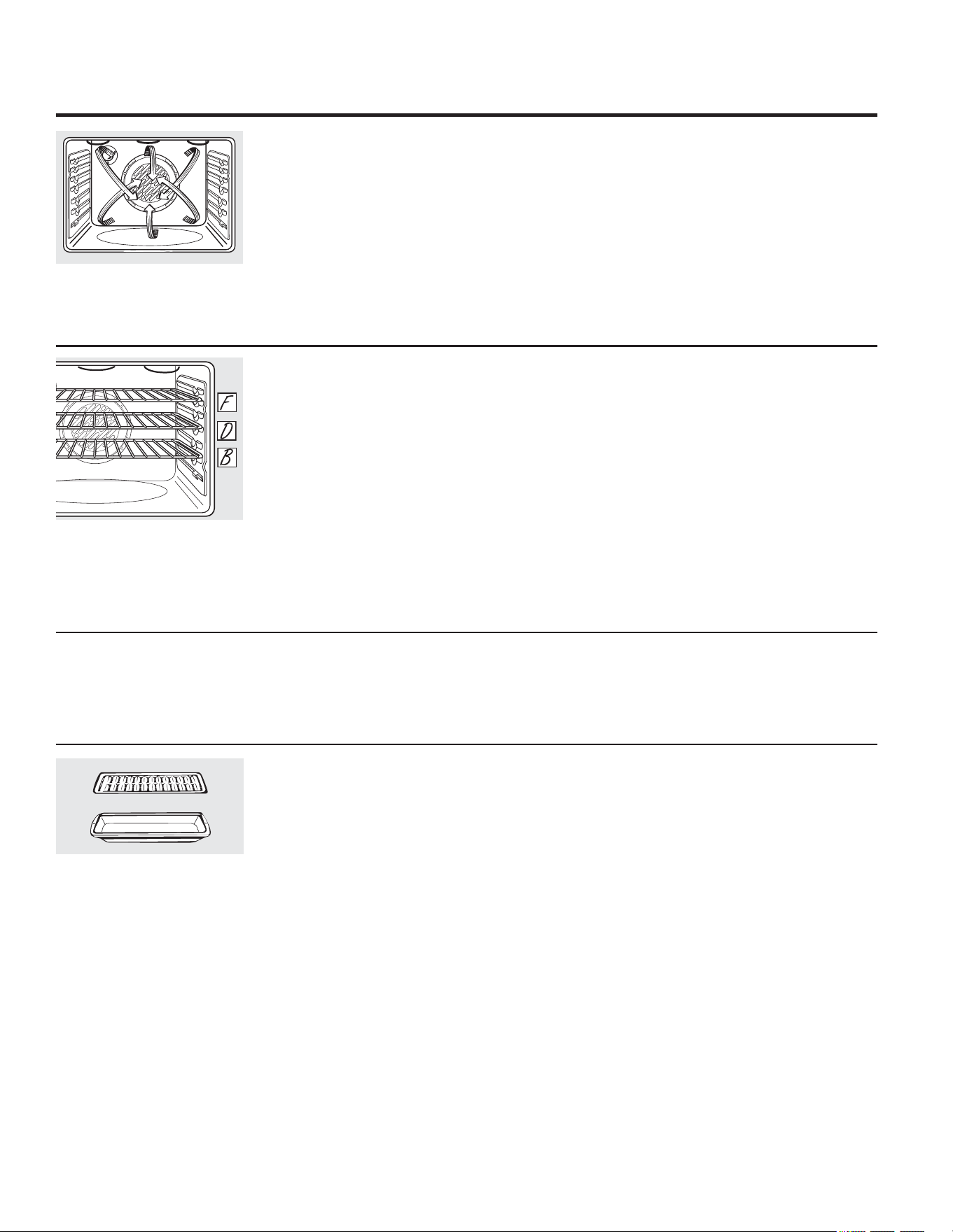
&yPRXVDUHOKRUQRGHFRQYHFFLyQHQDOJXQRVPRGHORV
'HELGRDTXHHODLUHFDOLHQWHFLUFXODHQIRUPD
SDUHMDHQWRGRHOKRUQRORVDOLPHQWRVSXHGHQ
KRUQHDUVHFRQH[FHOHQWHVUHVXOWDGRVXVDQGR
EDQGHMDVP~OWLSOHV
(OKRUQHDGRFRQEDQGHMDVP~OWLSOHVSXHGH
LQFUHPHQWDUXQSRFRORVWLHPSRVGHFRFFLyQ
GHDOJXQRVDOLPHQWRVSHURHOUHVXOWDGRWRWDO
HVHODKRUURGHWLHPSR/DVJDOOHWDVPXIILQV
EL]FRFKRV\RWURVSDQHVUiSLGRVORJUDQ
UHVXOWDGRVPX\EXHQRVFRQHOKRUQHDGRFRQ
EDQGHMDVP~OWLSOHV
&XDQGRKRUQHHFRQEDQGHMDVFRORTXHXQD
HQODVHJXQGD%SRVLFLyQRWUDHQODFXDUWD'
SRVLFLyQ\ODWHUFHUDHQODVH[WD)SRVLFLyQ
3DUDKRUQHDGRFRQGRVEDQGHMDVFRORTXH
XQDHQODVHJXQGD%SRVLFLyQ&RORTXHODRWUD
EDQGHMDHQODTXLWD(SRVLFLyQ
+RUQHDGRSRUFRQYHFFLyQFRQEDQGHMDVP~OWLSOHV
3RVLFLyQGHEDQGHMDVP~OWLSOHV
&XDQGRUHDOLFHXQKRUQHDGRSRUFRQYHFFLyQ
FRQVyOREDQGHMDFRORTXHORVDOLPHQWRVHQHO
FHQWURGHOKRUQR
+RUQHDGRSRUFRQYHFFLyQFRQEDQGHMDHQDOJXQRVPRGHORV
)XQFLRQDPLHQWRGHOYHQWLODGRUGHFRQYHFFLyQ
(QXQKRUQRGHFRQYHFFLyQXQYHQWLODGRU
KDFHFLUFXODUDLUHFDOLHQWHVREUHSRUGHEDMR\
DOUHGHGRUGHORVDOLPHQWRV
(VWDFLUFXODFLyQGHDLUHFDOLHQWHVHGLVWULEX\HGH
PDQHUDSDUHMDDWUDYpVGHODFDYLGDGGHOKRUQR
&RPRUHVXOWDGRORVDOLPHQWRVVHFRFLQDQ\
GRUDQHQIRUPDSDUHMDDPHQXGRHQPHQRV
WLHPSR
127$(QDOJXQRVPRGHORVHOYHQWLODGRUIXH
GLVHxDGRSDUDJLUDUHQDPEDVGLUHFFLRQHVFRQ
XQDSDXVDLQWHUPHGLD(VWRHVQRUPDO
(OYHQWLODGRUGHFRQYHFFLyQVHDSDJDFXDQGR
VHDEUHODSXHUWDGHKRUQR12'(-(ODSXHUWD
DELHUWDGXUDQWHSHUtRGRVSURORQJDGRVPLHQWUDV
XWLOL]DODFRFFLyQSRUFRQYHFFLyQ\DTXHSXHGH
DFRUWDUODYLGD~WLOGHOHOHPHQWRFDOHQWDGRUGH
FRQYHFFLyQ
5HMLOOD
$VDGHUD
%XHQRSDUDJUDQGHVFRUWHVGHFDUQHWLHUQD
VLQFXEULU
(OYHQWLODGRUGHFRQYHFFLyQKDFHFLUFXODU
HODLUHFDOLHQWHHQIRUPDSDUHMDVREUH\
DOUHGHGRUGHORVDOLPHQWRV/DVFDUQHVGHUHV
\GHDYHVHGRUDQSRUFRPSOHWRFRPRVLVH
KXELHVHQFRFLQDGRFRQXQURVWL]DGRUJLUDWRULR
(ODLUHFDOLHQWHVHOODORVMXJRVUiSLGDPHQWH
SDUDORJUDUXQSURGXFWRMXJRVR\WLHUQR
PLHQWUDVDOPLVPRWLHPSRVHFUHDXQDULFD
FDSDH[WHUQDPDUUyQGRUDGD
&XDQGRHVWpURVWL]DQGRSRUFRQYHFFLyQUHVXOWD
LPSRUWDQWHTXHXWLOLFHODDVDGHUD
\ODSDUULOODSDUDPHMRUHVUHVXOWDGRVGH
URVWL]DGRSRUFRQYHFFLyQ/DDVDGHUD
VHXWLOL]DSDUDUHWHQHUORVGHUUDPHV
GHJUDVD\ODSDUULOODVHXVDSDUDSUHYHQLU
VDOSLFDGXUDVGHJUDVD
5RVWL]DGRSRUFRQYHFFLyQHQDOJXQRVPRGHORV
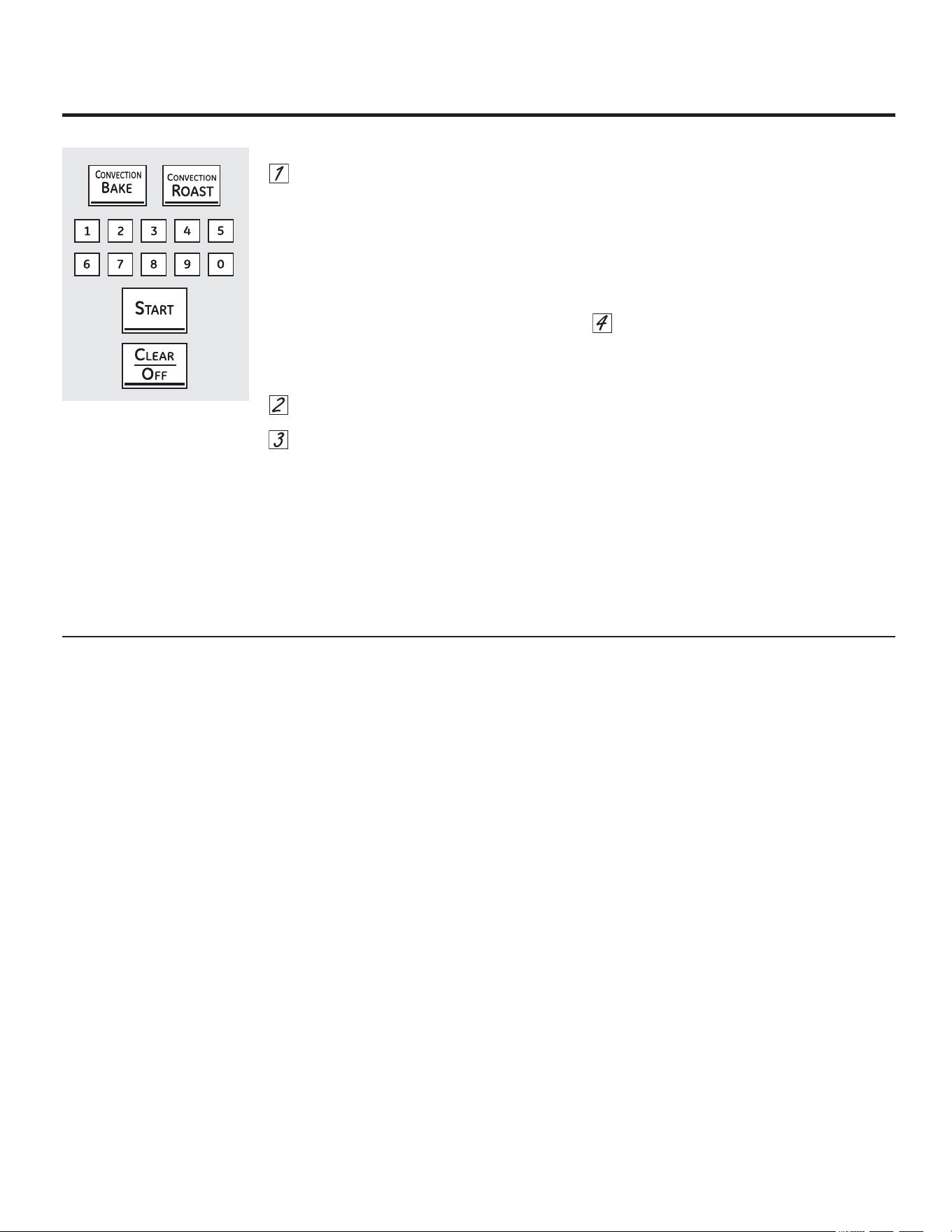
3UHVLRQHODWHFOD&219(&7,21%$.(
+RUQHDGRSRU&RQYHFFLyQHQDOJXQRV
PRGHORVXQDYHFHVSDUDKRUQHDUSRU
FRQYHFFLyQFRQP~OWLSOHVSDUULOODV
&RQVXOWHODVHFFLyQGH+RUQHDGRSRU
&RQYHFFLyQFRQ0~OWLSOHV3DUULOODV
3UHVLRQHODWHFOD&219(&7,21%$.(
+RUQHDGRSRU&RQYHFFLyQXQDYH]SDUD
KRUQHDUSRUFRQYHFFLyQGRVSDUULOOD
&RQVXOWHODVHFFLyQGH+RUQHDGRSRU
&RQYHFFLyQFRQ3DUULOOD
3UHVLRQHHOERWyQ&219(&7,2152$67
URVWL]DGRSRUFRQYHFFLyQSDUDURVWL]DGR
SRUFRQYHFFLyQHQDOJXQRVPRGHORV
3UHVLRQHODVDOPRKDGLOODVQXPpULFDVSDUD
FRQILJXUDUODWHPSHUDWXUDGHOKRUQR
3UHVLRQHHOERWyQ67$57LQLFLDU
127$6LOD)XQFLyQGH&RQYHUVLyQ$XWR5HFLSH
VHHQFXHQWUDDFWLYDGDDXWRPiWLFDPHQWH
UHGXFLUiODWHPSHUDWXUDGHKRUQHDGRUHJXODUHQ
DSUR[LPDGDPHQWH)KDVWDODWHPSHUDWXUD
GHFRQYHFFLyQDSURSLDGDHQHOPRGRGH
KRUQHDGRSRUFRQYHFFLyQ/HD&RQYHUVLyQFRQ
$XWR5HFLSHHQODVHFFLyQGH&DUDFWHUtVWLFDV
(VSHFLDOHV
3DUDFDPELDUODWHPSHUDWXUDGHOKRUQRSUHVLRQH
HOERWyQ&219(&7,21%$.(KRUQHDGRSRU
FRQYHFFLyQR&219(&7,2152$67DVDGRSRU
FRQYHFFLyQ\OXHJRODVDOPRKDGLOODVQXPpULFDV
SDUDFRQILJXUDUODQXHYDWHPSHUDWXUD
&XDQGRHOKRUQRFRPLHQ]DDFDOHQWDUSRGUi
YHUVHODWHPSHUDWXUDFDPELDQWHFRPHQ]DQGR
D)&&XDQGRHOKRUQRDOFDQ]DOD
WHPSHUDWXUDFRQILJXUDGDVRQDUiQSLWLGRV
3UHVLRQHHOERWyQ&/($52))ERUUDU
DSDJDGRFXDQGRKD\DILQDOL]DGR
0LHQWUDVFRFLQHSRUFRQYHFFLyQVHRLUi
XQYHQWLODGRU(OYHQWLODGRUVHGHWHQGUi
FXDQGRVHDEUDODSXHUWDSHURHOFDORU
QRVHDSDJDUi
'XUDQWHHOKRUQHDGRSXHGHQHVFXFKDUVH
FKDVTXLGRVSURYHQLHQWHVGHOKRUQR
(VWRHVQRUPDO
&yPRFRQILJXUDUHOKRUQRSDUDKRUQHDGRRURVWL]DGRSRUFRQYHFFLyQ
*($SSOLDQFHVFRP
5HFLSLHQWHVSDUDFRFFLyQSRUFRQYHFFLyQ
$QWHVGHXWLOL]DUHOKRUQRGHFRQYHFFLyQYHULILTXH
TXHVXVHOHPHQWRVGHFRFFLyQGHMHQHVSDFLR
VXILFLHQWHSDUDODFLUFXODFLyQGHDLUHHQHOKRUQR
6LYDDKRUQHDUFRQYDULRVUHFLSLHQWHVGHMHXQ
HVSDFLRHQWUHHOORV$GHPiVDVHJ~UHVHGHTXH
ORVUHFLSLHQWHVQRVHWRTXHQHQWUHVtRWRTXHQODV
SDUHGHVGHOKRUQR
3DSHO\SOiVWLFR
/RVUHFLSLHQWHVGHSDSHO\SOiVWLFRUHVLVWHQWHV
DOFDORUUHFRPHQGDGRVSDUDXWLOL]DUHQ
KRUQHDGRQRUPDOWDPELpQSXHGHQXWLOL]DUVH
SDUDKRUQHDGRSRUFRQYHFFLyQSHURQRGHEHQ
XWLOL]DUVHDWHPSHUDWXUDVPiVHOHYDGDVTXHOD
WHPSHUDWXUDUHFRPHQGDGDSRUHOIDEULFDQWH
GHORVHOHPHQWRVGHFRFFLyQ7DPELpQSXHGHQ
XWLOL]DUVHHOHPHQWRVGHFRFFLyQSOiVWLFRV
UHVLVWHQWHVDWHPSHUDWXUDVGH)&
0HWDO\YLGULR
&XDOTXLHUWLSRGHUHFLSLHQWHGHFRFFLyQIXQFLRQD
HQVXKRUQRGHFRQYHFFLyQVLQHPEDUJR
ORVUHFLSLHQWHVGHPHWDOVHFDOLHQWDQPiV
UiSLGDPHQWH\VHUHFRPLHQGDQSDUDKRUQHDGR
SRUFRQYHFFLyQ
/DVEDQGHMDVRVFXUDVRFRQDFDEDGRPDWH
KRUQHDQDOLPHQWRVPiVUiSLGRTXHODV
EULOODQWHV
/RVUHFLSLHQWHVGHYLGULRRFHUiPLFDFRFLQDQ
PiVGHVSDFLR
3DUDUHFHWDVFRPRSROORKRUQHDGRXWLOLFHXQ
UHFLSLHQWHFRQODGRVEDMRV(ODLUHFDOLHQWHQRSXHGH
FLUFXODUELHQDOUHGHGRUGHORVDOLPHQWRVHQXQ
UHFLSLHQWHGHODGRVDOWRV
&XDQGRKRUQHHJDOOHWDVREWHQGUi
PHMRUHVUHVXOWDGRVVLXVDXQD
SODQFKDSODQDSDUDJDOOHWDVHQ
OXJDUGHXQUHFLSLHQWHGHODGRV
EDMRV
OR
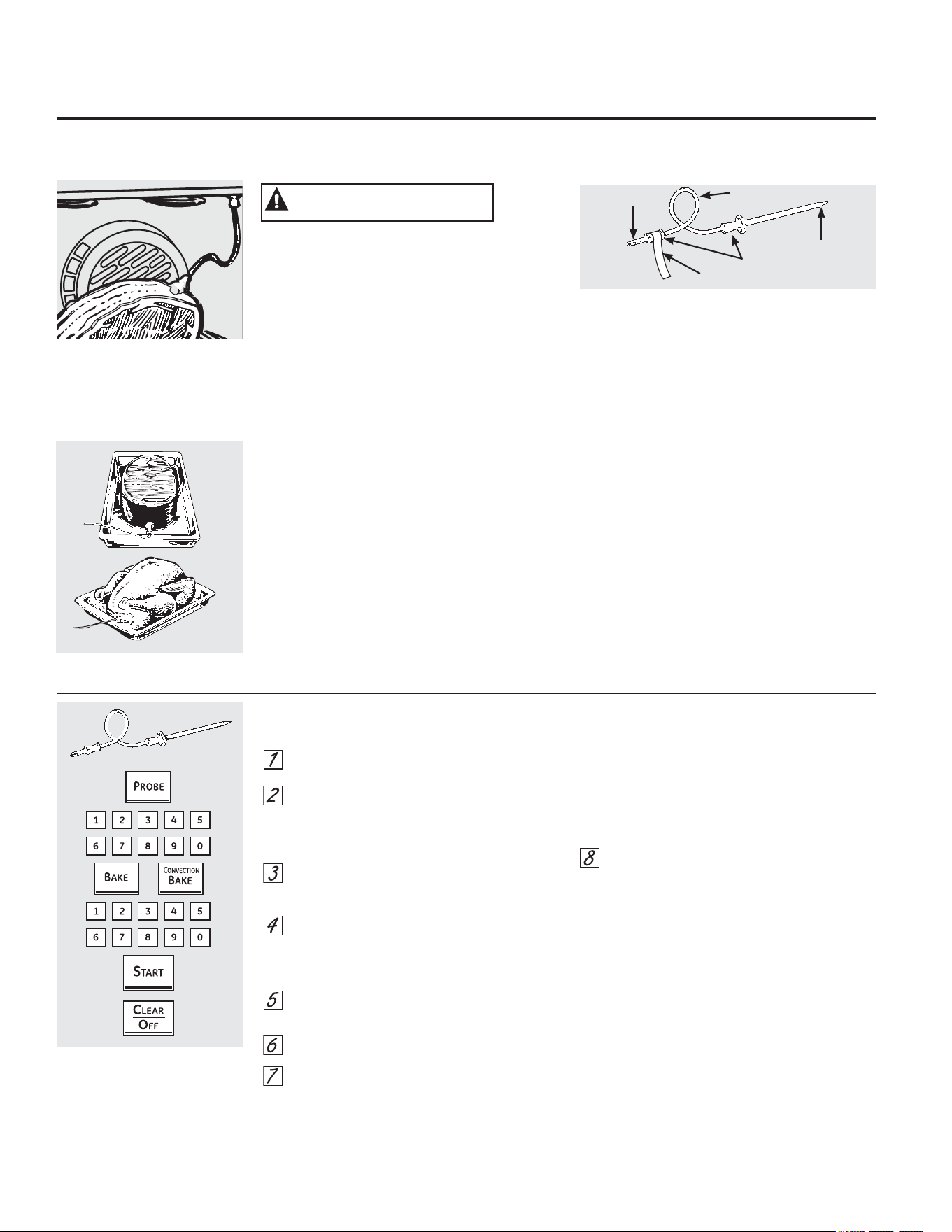
&yPRXVDUODVRQGDHQDOJXQRVPRGHORV
,QWURGX]FDODVRQGDSRUFRPSOHWRHQORV
DOLPHQWRV
(QFKXIHODVRQGDGHQWURGHODERFDGHVDOLGD
GHOKRUQR9HULILTXHTXHHVWpLQWURGXFLGDKDVWD
HOIRQGR&LHUUHODSXHUWDGHOKRUQR9HULILTXH
TXHHOFDEOHGHODVRQGDQRWRTXHHOHOHPHQWR
DVDGRU
3UHVLRQHHOERWyQ352%(VRQGD
/DSDQWDOODPRVWUDUi
´6HW3UREHµ
7HPSHUDWXUDGHOD6RQGD
3UHVLRQHODVDOPRKDGLOODVQXPpULFDV
SDUDFRQILJXUDUODWHPSHUDWXUDLQWHUQD
GHVHDGDGHORVDOLPHQWRVRGHODFDUQH/D
WHPSHUDWXUDLQWHUQDPi[LPDDODTXHSXHGHQ
FRQILJXUDUVHORVDOLPHQWRVHV)&
3UHVLRQHODWHFOD%$.(+RUQHDUR
&219(&7,21&RQYHFFLyQ
3UHVLRQHODVDOPRKDGLOODVQXPpULFDVSDUD
FRQILJXUDUODWHPSHUDWXUDGHVHDGDGHOKRUQR
3UHVLRQHHOERWyQ67$57LQLFLDU
/DSDQWDOODGHVWHOODUiVLODVRQGDVHHQFXHQWUD
HQFKXIDGDGHQWURGHODERFDGHVDOLGD\XVWHGQRKD
FRQILJXUDGRXQDWHPSHUDWXUDGHVRQGD
\SUHVLRQDGRHOERWyQ67$57LQLFLDU
3UHVLRQHODWHFOD352%(6RQGDSDUDUHFRUGDUOD
WHPSHUDWXUDGHODVRQGDRODWHFOD%$.(+RUQHDU
R&219(&7,21&RQYHFFLyQSDUDUHFRUGDUOD
WHPSHUDWXUDGHOKRUQR3DUDODWHPSHUDWXUDGH
ODVRQGDOXHJRGHTXHODWHPSHUDWXUDLQWHUQDGH
ODFRPLGDDOFDQFHORV)ORVFDPELRVGHOD
WHPSHUDWXUDLQWHUQDDSDUHFHUiQHQODSDQWDOOD
&XDQGRODWHPSHUDWXUDLQWHUQDGHORV
DOLPHQWRVDOFDQ]DODFLIUDTXHXVWHGKD
FRQILJXUDGRODVRQGD\HOKRUQRVHDSDJDQ\
ORVFRQWUROHVGHOKRUQRFRPLHQ]DQDGHVWHOODU
3DUDGHWHQHUHOGHVWHOORSUHVLRQHHOERWyQ
&/($52))ERUUDUDSDJDGR8WLOLFHJXDQWHV
GHFRFLQDSDUDTXLWDUODVRQGDGHORVDOLPHQWRV
1RXWLOLFHSLQ]DVSDUDTXLWDUODSRUTXHSRGUtDQ
GDxDUOD
6LODVRQGDVHTXLWDGHOKRUQRPLHQWUDV
VHHVWDEDFRFLQDQGRHOKRUQRQRVHDSDJDUi
DXWRPiWLFDPHQWH
3DUDFDPELDUODWHPSHUDWXUDGHOKRUQRGXUDQWHHO
FLFORGHKRUQHDGRURVWL]DGRSUHVLRQHHOERWyQ%$.(
KRUQHDUR&219(&7,21FRQYHFFLyQ\OXHJRODV
DOPRKDGLOODVQXPpULFDVSDUDFRQILJXUDUODQXHYD
WHPSHUDWXUD
3XHGHXWLOL]DUHOWHPSRUL]DGRUGHFRFLQDDXQTXH
QRSXHGHQXVDUVHRSHUDFLRQHV
GHOKRUQRFRQWHPSRUL]DGRUPLHQWUDVVHXWLOLFHOD
VRQGD
3DUDHYLWDUTXHPDGXUDVQRGHVHQFKXIHODVRQGDGH
ODERFDGHVDOLGDGHOKRUQRKDVWDTXHpVWHVHKD\D
HQIULDGR
(OXVRGHVRQGDVGLVWLQWDVDODVSURYLVWDVFRQHVWH
SURGXFWRSXHGHSURYRFDUOHVGDxRVDODVPLVPDVRDO
FRQWUROGHOKRUQR
8WLOLFHODVPDQLMDVGHODVRQGD\HOHQFKXIHFXDQGR
ODVLQWURGX]FD\TXLWHGHORVDOLPHQWRV\GHODERFD
GHVDOLGD
3DUDHYLWDUGDxRVDODVRQGDQRXWLOLFHSLQ]DVSDUD
WLUDUGHOFDEOHFXDQGRORTXLWH
3DUDQRURPSHUODVRQGDYHULILTXHTXHORV
DOLPHQWRVHVWpQWRWDOPHQWHGHVFRQJHODGRVDQWHV
GHLQWURGXFLUOD
'HVSXpVGHSUHSDUDUODFDUQH\FRORFDUODHQXQ
SRVDIXHQWHVRVREUHODUHMLOODGHODDVDGHUDVLJDHVWDV
LQVWUXFFLRQHVSDUDXQDFRORFDFLyQDGHFXDGDGHOD
VRQGD
,QWURGX]FDODVRQGDFRPSOHWDPHQWHHQODFDUQH1R
GHEHWRFDUKXHVRJUDVDRFDUWtODJR
127$1RLQVHUWDUSRUFRPSOHWRODVRQGDGHQWURGHOD
FDUQHSXHGHSURYRFDUXQSREUHGHVHPSHxRGHFRFFLyQ
SRUTXHODVRQGDGHWHFWDUiHODLUHGHOKRUQR\QROD
WHPSHUDWXUDGHORVDOLPHQWRV
1XQFDGHMHODVRQGDGHQWURGHOKRUQRGXUDQWHXQ
FLFORGHDXWROLPSLH]DRGHDVDGR
1RJXDUGHODVRQGDGHQWURGHOKRUQR
3DUDDVDGRVVLQKXHVRLQWURGX]FDODVRQGDGHQWUR
GHODSDUWHPiVFDUQRVD3DUDMDPyQRFRUGHURFRQ
KXHVRLQWURGX]FDODVRQGDHQHOFHQWURGHOP~VFXOR
JUDQGHPiVEDMR
,QWURGX]FDODVRQGDHQHOFHQWURGHSODWRVWDOHV
FRPRSDQGHFDUQHRHVWRIDGRV
,QWURGX]FDODVRQGDGHQWURGHODSDUWHPiVFDUQRVD
GHOPXVORLQWHUQRGHVGHDEDMR\HQIRUPDSDUDOHODD
ODSDWDGHXQSDYRHQWHUR
127$1RVHSRGUiQXWLOL]DUODVFRQILJXUDFLRQHVGH
DXWROLPSLH]DQLGHDVDGRVLODVRQGDGHWHPSHUDWXUD
VHHQFXHQWUDHQFKXIDGD
/DVRQGDGHWHPSHUDWXUDFXHQWD
FRQXQDVRQGDVLPLODUDXQSLQFKR
HQXQH[WUHPR\XQHQFKXIHHQHO
RWURH[WUHPRTXHVHLQWURGXFHHQ
ODERFDGHVDOLGDGHOKRUQR
&yPRFRQILJXUDUHOKRUQRSDUDKRUQHDGRURVWL]DGRFXDQGRXVDODVRQGD
HQDOJXQRVPRGHORV
OR
(QFKXIH
&DEOH
0DQLMDV
6RQGD
(QPXFKRVDOLPHQWRVHVSHFLDOPHQWHDVDGRV\FDUQHVGHDYHODWHPSHUDWXUDLQWHUQDGHORVDOLPHQWRVHVODPHMRUSUXHEDSDUD
YHULILFDUHOJUDGRGHFRFFLyQ0HGLDQWHODVRQGDGHWHPSHUDWXUDVHHYLWDWHQHUTXHDGLYLQDUHOJUDGRGHFRFFLyQ
\VHORJUDHOSXQWRGHFRFFLyQH[DFWR
/HD\TXLWHODHWLTXHWD
35(&$8&,Ï1
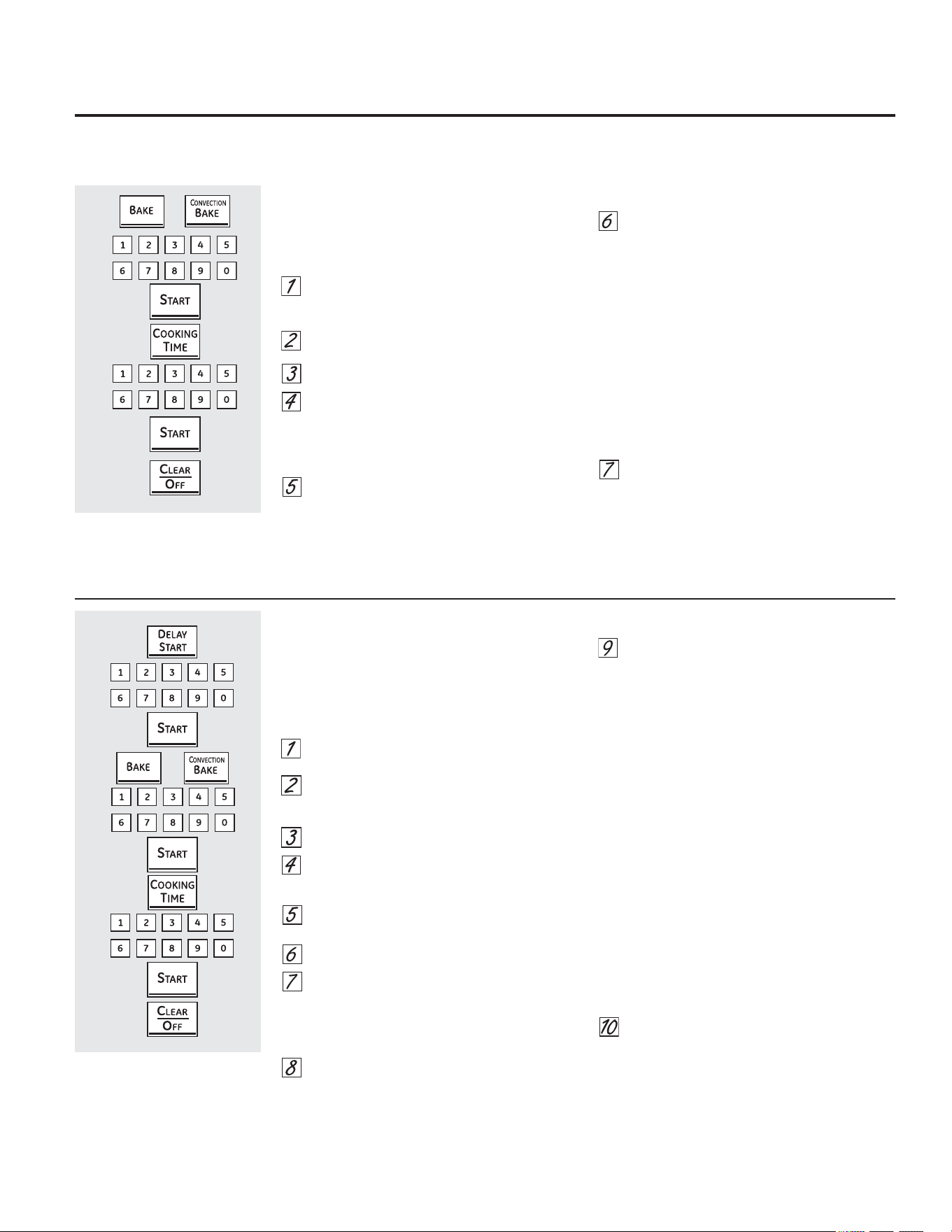
&yPRXWLOL]DUODVFDUDFWHUtVWLFDVGHKRUQHDGR
\URVWL]DGRFRQWHPSRUL]DGRU *($SSOLDQFHVFRP
&yPRFRQILJXUDUXQLQLFLRLQPHGLDWR\XQDSDJDGRDXWRPiWLFR
(OKRUQRVHHQFLHQGHLQPHGLDWDPHQWH
\FRFLQDORVDOLPHQWRVGXUDQWHXQSHUtRGRGH
WLHPSRVHOHFFLRQDGR$OILQDOL]DUHOWLHPSRGH
FRFFLyQHOKRUQRVHDSDJDDXWRPiWLFDPHQWH
3UHVLRQHHOERWyQ%$.(KRUQHDUR
&219(&7,21%$.(+RUQHDGRSRU
&RQYHFFLyQ
3UHVLRQHODVDOPRKDGLOODVQXPpULFDVSDUD
FRQILJXUDUODWHPSHUDWXUDGHVHDGDGHOKRUQR
3UHVLRQHODWHFOD67$57,QLFLDU
3UHVLRQHHOERWyQ&22.,1*7,0(WLHPSR
GHFRFFLyQ
127$6LVXUHFHWDUHTXLHUHSUHFDOHQWDPLHQWR
SXHGHQHFHVLWDUDJUHJDUWLHPSRDGLFLRQDO
DOWLHPSRGHFRFFLyQ
3UHVLRQHODVDOPRKDGLOODVQXPpULFDVSDUD
FRQILJXUDUHOWLHPSRGHFRFFLyQGHVHDGR
(OWLHPSRGHFRFFLyQPtQLPRTXHXVWHG
SXHGHFRQILJXUDUHVPLQXWR
/DWHPSHUDWXUDGHOKRUQRTXHKD
FRQILJXUDGR\HOWLHPSRGHFRFFLyQ
LQJUHVDGRDSDUHFHUiQHQODSDQWDOOD
3UHVLRQHHOERWyQ67$57LQLFLDU
(OKRUQRHVWDUiHQODSRVLFLyQ21(QFHQGLGR\
HQODSDQWDOODDSDUHFHUiHOFRQWHRGHODFRFFLyQ
\HOFDPELRGHWHPSHUDWXUDDSDUWLUGHORV
)/DSDQWDOODGHWHPSHUDWXUDFRPHQ]DUiD
FDPELDUXQDYH]TXHODWHPSHUDWXUDGHOKRUQR
DOFDQFHORV)&XDQGRHOKRUQRDOFDQFHOD
WHPSHUDWXUDTXHSURJUDPyVRQDUiQSLWLGRV
(OKRUQRFRQWLQXDUiFRFLQDQGRGXUDQWHOD
FDQWLGDGGHWLHPSRFRQILJXUDGD\OXHJR
GHDSDJDUiGHIRUPDDXWRPiWLFDDPHQRV
TXHODIXQFLyQ:$50&DOHQWDUKD\DVLGR
FRQILJXUDGD/HDODVHFFLyQ&yPR&RQILJXUDUHO
+RUQRSDUD&DOHQWDU
6LIXHUDQHFHVDULRSUHVLRQHHOERWyQ
&/($52))ERUUDUDSDJDGRSDUDERUUDU
ODSDQWDOOD4XLWHORVDOLPHQWRVGHOKRUQR
5HFXHUGHDXQTXHHOKRUQRVHDSDJD
DXWRPiWLFDPHQWHORVDOLPHQWRVTXHVH
GHMHQHQHOKRUQRVHJXLUiQFRFLQiQGRVH
GHVSXpVGHDSDJDGRHOPLVPR
&yPRFRQILJXUDUXQLQLFLRUHWDUGDGR\XQDSDJDGRDXWRPiWLFR
(OKRUQRVHHQFHQGHUiHQHOKRUDULRTXH
XVWHGKD\DFRQILJXUDGRFRFLQDUiDOLPHQWRV
GXUDQWHXQSHUtRGRGHWLHPSRHVSHFtILFR
\OXHJRVHDSDJDUiDXWRPiWLFDPHQWH
$VHJ~UHVHGHTXHHOUHORMPXHVWUHODKRUD
FRUUHFWD
3UHVLRQHODWHFOD'(/$<67$57,QLFLR
5HWUDVDGR
3UHVLRQHODVDOPRKDGLOODVQXPpULFDV
SDUDFRQILJXUDUODWHPSHUDWXUDGHVHDGD
GHOKRUQR
3UHVLRQHODWHFOD67$57,QLFLDU
3UHVLRQHODWHFOD%$.(+RUQHDUR
&219(&7,21%$.(+RUQHDGRSRU
&RQYHFFLyQXRWUDIXQFLyQGHFRFFLyQGHVHDGD
7RTXHORVODVWHFODVQXPpULFDVSDUD
SURJUDPDUODWHPSHUDWXUDGHOKRUQRGHVHDGD
3UHVLRQHODWHFOD67$57,QLFLDU
3UHVLRQHODWHFOD&22.,1*7,0(7LHPSR
GH&RFFLyQ
127$6LVXUHFHWDUHTXLHUHSUHFDOHQWDPLHQWR
SXHGHQHFHVLWDUDJUHJDUWLHPSRDGLFLRQDODO
WLHPSRGHFRFFLyQ
3UHVLRQHODVDOPRKDGLOODVQXPpULFDVSDUD
FRQILJXUDUHOWLHPSRGHFRFFLyQGHVHDGR
(OWLHPSRGHFRFFLyQPtQLPRTXHXVWHG
SXHGHFRQILJXUDUHVPLQXWR
/DWHPSHUDWXUDGHOKRUQRTXHKD
FRQILJXUDGR\HOWLHPSRGHFRFFLyQ
LQJUHVDGRDSDUHFHUiQHQODSDQWDOOD
3UHVLRQHHOERWyQ67$57LQLFLDU
127$6LGHVHDYHULILFDUORVKRUDULRVTXH
KDFRQILJXUDGRSUHVLRQHHOERWyQ'(/$<
67$57LQLFLRUHWDUGDGRSDUDFRQWURODUOD
KRUDGHLQLFLRFRQILJXUDGDRSUHVLRQHHO
ERWyQ&22.,1*7,0(7LHPSRGH&RFFLyQ
SDUDYHULILFDUODH[WHQVLyQGHFRFFLyQTXHKD
FRQILJXUDGR
&XDQGRHOKRUQRVHHQFLHQGH21HQ
HOKRUDULRTXHKDFRQILJXUDGRODSDQWDOOD
PRVWUDUiODFXHQWDUHJUHVLYDGHOWLHPSR
GHFRFFLyQ\ODQXHYDWHPSHUDWXUD
FRPHQ]DQGRHQ)&/DSDQWDOOD
GHWHPSHUDWXUDFRPHQ]DUiDFDPELDU
FXDQGRODWHPSHUDWXUDGHOKRUQROOHJXHD
ORV)>&@&XDQGRHOKRUQRDOFDQ]DOD
WHPSHUDWXUDFRQILJXUDGDVRQDUiQSLWLGRV
(OKRUQRVHJXLUiFRFLQDQGRGXUDQWHXQ
SHUtRGRGHWLHPSRGHWHUPLQDGR\OXHJR
VHDSDJDUiDXWRPiWLFDPHQWHDPHQRV
TXHODIXQFLyQ:$50&DOHQWDUKD\DVLGR
FRQILJXUDGD/HDODVHFFLyQ&yPR&RQILJXUDUHO
+RUQRSDUD&DOHQWDU
6LIXHUDQHFHVDULRSUHVLRQHHOERWyQ
&/($52))ERUUDUDSDJDGRSDUD
ERUUDUODSDQWDOOD4XLWHORVDOLPHQWRV
GHOKRUQR5HFXHUGHDXQTXHHOKRUQRVH
DSDJDDXWRPiWLFDPHQWHORVDOLPHQWRV
TXHVHGHMHQHQHOKRUQRVHJXLUiQ
FRFLQiQGRVHGHVSXpVGHDSDJDGR
HOPLVPR
127$/RVDOLPHQWRVTXHVHHFKDQDSHUGHUFRQIDFLOLGDG³FRPROHFKHKXHYRVSHVFDGRUHOOHQRVFDUQHGHDYH\FHUGR³QRGHEHQGHMDUVH
UHSRVDUSRUPiVGHKRUDDQWHV\GHVSXpVGHODFRFFLyQ/DWHPSHUDWXUDDPELHQWHSURPXHYHHOFUHFLPLHQWRGHEDFWHULDVGDxLQDV
9HULILTXHTXHODOX]GHOKRUQRHVWpDSDJDGDSRUTXHHOFDORUSURYHQLHQWHGHODERPELOODSXHGHDFHOHUDUHOFUHFLPLHQWRGHEDFWHULDV
OR
OR
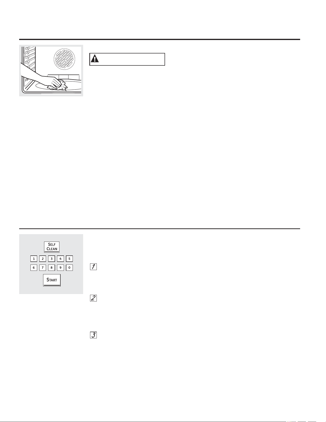
8VRGHOKRUQRFRQDXWROLPSLH]D
&yPRFRQILJXUDUHOKRUQRSDUDXQDDXWROLPSLH]D
/DVSXHUWDGHOKRUQRGHEHHVWDUFHUUDGDV\WRGRV
ORVFRQWUROHVGHEHQHVWDUFRUUHFWDPHQWHFRQILJXUDGRV
SDUDTXHHOFLFORIXQFLRQHHQIRUPDDGHFXDGD
3UHVLRQHHOERWyQ6(/)&/($1DXWROLPSLH]D
6HUHFRPLHQGDXQFLFORGHKRUDVSDUDOLPSLDU
GHUUDPHVSHTXHxRV\FRQWHQLGRV6HUHFRPLHQGD
XQFLFORGHDXWROLPSLH]DGHKRUDVSDUDXQ
KRUQRPiVVXFLR
6LQHFHVLWDXQFLFORGLIHUHQWHGHRKRUDVXWLOLFH
ODVDOPRKDGLOODVQXPpULFDVHLQJUHVHHOWLHPSRGH
OLPSLH]DGHVHDGR
(OWLHPSRGHOLPSLH]DSXHGHFRQILJXUDUVHHQWUHKRUDV
\KRUDVGHDFXHUGRFRQHOJUDGRGHVXFLHGDGGHO
KRUQR
3UHVLRQHHOERWyQ67$57LQLFLDU
/DVSXHUWDVGHOKRUQRVXSHULRUHLQIHULRUVHEORTXHDQ
DXWRPiWLFDPHQWH/RVHOHPHQWRVGHODHVWXIDWDPELpQ
VHEORTXHDQGXUDQWHODOLPSLH]D/DSDQWDOODPRVWUDUi
HOWLHPSRGHOLPSLH]DUHVWDQWH1RSRGUiQDEULUVH
ODVSXHUWDVGHOKRUQRRXWLOL]DUODHVWXIDKDVWDTXHOD
WHPSHUDWXUDGHVFLHQGDSRUGHEDMRGHODWHPSHUDWXUD
GHEORTXHR\VHDSDJXH/2&.('%ORTXHDGRGHOD
SDQWDOODGHFRQWURO
6LXVWHGFRQILJXUDHOFLFORGHOLPSLH]D\VHROYLGD
GHFHUUDUODVSXHUWDVGHOKRUQRGHVWHOODUi/2&.('
%ORTXHDGR\ODSDODEUDGRRUSXHUWDDSDUHFHUiHQ
ODSDQWDOOD
3DUDGHWHQHUHOFLFORGHOLPSLH]DSUHVLRQHHOERWyQ
&/($52))ERUUDUDSDJDGR&XDQGRVHDSDJD
/2&.('%ORTXHDGRSXHUWDEORTXHDGDLQGLFDQGR
TXHODWHPSHUDWXUDGHORVKRUQRVKDGHVFHQGLGRSRU
GHEDMRGHODWHPSHUDWXUDGHEORTXHRXVWHGSRGUi
DEULUODVSXHUWDV
/LPSLHFRQXQSDxRORVGHVHFKRV
UHEHOGHVDFXPXODGRVHQHOSLVRGHO
KRUQR
$QWHVGHXQFLFORGH$XWR/LPSLH]D
3(/,*52'(,1&(1',2/LPSLHODJUDVD\ODVXFLHGDG
UHEHOGHGHOSLVRGHOKRUQRDQWHVGHODDXWROLPSLH]D
1RKDFHUORSXHGHSURYRFDUXQLQFHQGLRHQHOKRUQR
5HFRPHQGDPRVYHQWLODUVXFRFLQDFRQXQDYHQWDQD
DELHUWDRXWLOL]DQGRXQYHQWLODGRURFDPSDQD
GXUDQWHHOSULPHUFLFORGHDXWROLPSLH]D
4XLWHODDVDGHUDUHMLOODVRQGDWRGRVORVUHFLSLHQWHV
GHFRFFLyQ\FXDOTXLHUWUR]RGHSDSHOGHDOXPLQLRGHO
KRUQR
127$6
6LHOKRUQRVHHQFXHQWUDHTXLSDGRFRQSDUULOODV
SDUDKRUQREULOORVDV\GHFRORUSODWHDGRVH
UHFRPLHQGDUHWLUDUODVPLVPDVDQWHVGHFRPHQ]DU
FRQHOFLFORGHDXWROLPSLH]D3RGUiQSHUPDQHFHU
HQHOKRUQRGXUDQWHHOFLFORGHDXWROLPSLH]DSHUR
VHRVFXUHFHUiQSHUGHUiQVXOXVWUH\VHUiGLItFLO
GHVOL]DUODV
6LVXKRUQRHVWiHTXLSDGRFRQEDQGHMDVUHYHVWLGDV
GHSRUFHODQDJULVSXHGHQGHMDUVHGHQWURGHOKRUQR
GXUDQWHHOFLFORGHDXWROLPSLH]D
/DVXFLHGDGXELFDGDHQHOPDUFRIURQWDOGHODFRFLQD
\IXHUDGHODMXQWDGHODSXHUWDGHEHUiOLPSLDUVH
DPDQR/LPSLHHVWDViUHDVFRQDJXDFDOLHQWH
HVSRQMLOODVGHODQDGHDFHURHPEHELGDVHQMDEyQR
OLPSLDGRUHVWDOHVFRPR6RIW6FUXE
(QMXDJXHELHQ
FRQDJXDOLPSLD\VHTXH
1ROLPSLHODMXQWD(OPDWHULDOGHILEUDGHYLGULRGH
ODMXQWDGHODSXHUWDGHOKRUQRQRUHVLVWHSURGXFWRV
DEUDVLYRV(VHVHQFLDOTXHODMXQWDVHPDQWHQJD
LQWDFWD6LXVWHGQRWDTXHHVWiGHVJDVWDGD
UHHPSOiFHOD
9HULILTXHTXHODWDSDGHODERPELOODGHOX]GHOKRUQR
HVWpHQVXOXJDU\TXHODOX]GHOKRUQRHVWpDSDJDGD
,03257$17(/DVHPDQDFLRQHVSURGXFLGDVSRU
HOFLFORGHDXWROLPSLH]DGHFXDOTXLHUKRUQRDIHFWDQ
ODVDOXGGHDOJXQDVDYHVGHPDQHUDQRWRULD3URFXUH
OOHYDUVXVDYHVDRWUDKDELWDFLyQELHQYHQWLODGD
0RGHORVFDQDGLHQVHVVRODPHQWH
/DVXQLGDGHVGHVXSHUILFLHVHGHVDFWLYDQ
DXWRPiWLFDPHQWHGXUDQWHHOFLFORGHDXWROLPSLH]D
9HULILTXHTXHWRGRVORVFRQWUROHVGHXQLGDGHV
GHVXSHUILFLHHVWpQDSDJDGRVHQWRGRPRPHQWR
GXUDQWHHOFLFORGHDXWROLPSLH]D&XDOTXLHUXQLGDG
GHVXSHUILFLHFRQILJXUDGDHQXQDSRVLFLyQ´RQµ
HQFHQGLGRPLHQWUDVIXQFLRQDHOFLFORGHDXWR
OLPSLH]DVHDFFLRQDUiDXWRPiWLFDPHQWHGHVSXpVGH
WHUPLQDGRHOFLFOR\SXHGHSURYRFDUHOHQFHQGLGR
GHXQDXQLGDGGHVXSHUILFLH\TXHGDUVLQDWHQFLyQ
(VSHUHKDVWDTXHWHUPLQHHOFLFORGHDXWROLPSLH]D
SDUD
FRQILJXUDU\XVDUODVXQLGDGHVGHVXSHUILFLH
$'9(57(1&,$
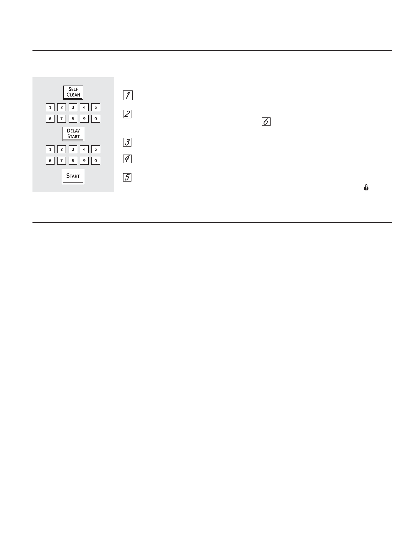
*($SSOLDQFHVFRP
&yPRFRQILJXUDUXQLQLFLRUHWDUGDGRGHOLPSLH]D
3UHVLRQHHOERWyQ'(/$<67$57LQLFLR
UHWDUGDGR
0HGLDQWHODVDOPRKDGLOODVQXPpULFDV
LQJUHVHODKRUDHQTXHGHVHDLQLFLDU
HOFLFORGHOLPSLH]D
3UHVLRQHHOERWyQ67$57LQLFLDU
3UHVLRQHHOERWyQ6(/)&/($1DXWR
OLPSLH]D
6LHVQHFHVDULRXQWLHPSRGLIHUHQWHDO
SUHFRQILJXUDGRXWLOLFHODVWHFODV
QXPpULFDVHLQJUHVHHO1XHYRWLHPSR
GHVHDGR
(OWLHPSRGHOLPSLH]DSXHGHFRQILJXUDUVHHQWUH
KRUDV\KRUDVGHDFXHUGRFRQHOJUDGRGH
VXFLHGDGGHOKRUQR
3UHVLRQHHOERWyQ67$57LQLFLDU
/DSXHUWDGHOKRUQRVHFLHUUDDXWRPiWLFDPHQWH
/RVHOHPHQWRVGHODHVWXIDWDPELpQVH
EORTXHDQGXUDQWHODDXWROLPSLH]D/DSDQWDOOD
PRVWUDUiODKRUDGHLQLFLR
1RSRGUiQDEULUVHODVSXHUWDVGHOKRUQRR
XWLOL]DUVHODHVWXIDKDVWDTXHODWHPSHUDWXUD
GHVFLHQGDSRUGHEDMRGHODWHPSHUDWXUDGH
EORTXHR\VHDSDJXH/2&.(''225 SXHUWD
EORTXHDGDGHODSDQWDOODGHFRQWURO
/DVSXHUWDVGHOKRUQRGHEHHVWDUFHUUDGDV\WRGRVORVFRQWUROHVGHEHQHVWDUFRUUHFWDPHQWHFRQILJXUDGRVSDUDTXHHOFLFOR
IXQFLRQHHQIRUPDDGHFXDGD
'HVSXpVGHXQFLFORGHOLPSLH]D
(VSRVLEOHTXHREVHUYHDOJXQDVFHQL]DVEODQFDV
HQHOKRUQR/tPSLHODVFRQXQSDxRK~PHGR
GHVSXpVGHTXHHOKRUQRVHHQIUtH
6LODVPDQFKDVEODQFDVSHUPDQHFHQ
UHPXpYDODVFRQXQHVWURSDMRGHDFHUROOHQR
GHMDEyQ\HQMXDJXHJHQHURVDPHQWHFRQXQD
PH]FODGHYLQDJUH\DJXD(VWRVGHSyVLWRV
VRQXVXDOPHQWHUHVLGXRVGHVDOTXHHOFLFORGH
OLPSLH]DQRSXHGHHOLPLQDU
6LHOKRUQRQRTXHGDOLPSLRGHVSXpVGHXQFLFOR
GHOLPSLH]DUHSLWDHOFLFOR
8VWHGQRSXHGHFRQILJXUDUHOKRUQR
SDUDFRFFLyQKDVWDTXHHOKRUQRHVWpOR
VXILFLHQWHPHQWHIUtRFRPRSDUDTXHODSXHUWD
VHGHVEORTXHH
0LHQWUDVHOKRUQRHVWpHQDXWROLPSLH]D
XVWHGSXHGHSUHVLRQDUHOERWyQ5(/2-SDUD
PRVWUDUHQSDQWDOODODKRUDGHOGtD3DUD
YROYHUDODFXHQWDUHJUHVLYDGHOLPSLH]D
SUHVLRQHHOERWyQ$872/,03,(=$
3DUULOODVHVWiQGDU
6LUHVXOWDGLItFLOGHVOL]DUODVSDVHDFHLWHGH
FRFFLyQFRQXQSDxRHQVXVFRVWDGRVODWHUDOHV
\HQORVVRSRUWHVGHODVSDUULOODVGHOKRUQR
3DUULOODGHH[WHQVLyQ
6LGHVOL]DUODPLVPDUHVXOWDGLItFLOYHU3DUULOODGH
H[WHQVLyQHQODVHFFLyQ&XLGDGR\OLPSLH]D1R
URFtHODSDUULOODGHH[WHQVLyQFRQSXOYHUL]DGRU
SDUDFRFFLyQXRWURVOXEULFDQWHVHQVSUD\
6LUHVXOWDGLItFLOTXLWDUODRFRORFDUODSDVHDFHLWH
GHFRFFLyQFRQXQSDxRHQORVVRSRUWHVGHODV
SDUULOODVGHOKRUQR1RSDVHDFHLWHGHFRFFLyQ
HQORVGHVOL]DGRUHV
127$/XHJRGHOSULPHUFLFORGHOLPSLH]D
DXWRPiWLFDODVVXSHUILFLHVGHDFHURLQR[LGDEOH
JULVFDPELDUiQGHFRORUHQORVHVWDQWHV
H[WHQVLEOHVHVPDOWDGRV(VWRHVQRUPDO1RVH
UHFRPLHQGDODOLPSLH]DDXWRPiWLFDGHHVWDQWHV
H[WHQVLEOHVGHQtTXHO\DTXHWRGRHOHVWDQWH
SHUGHUiFRORUGHELGRDODVWHPSHUDWXUDVGHOD
OLPSLH]DDXWRPiWLFD
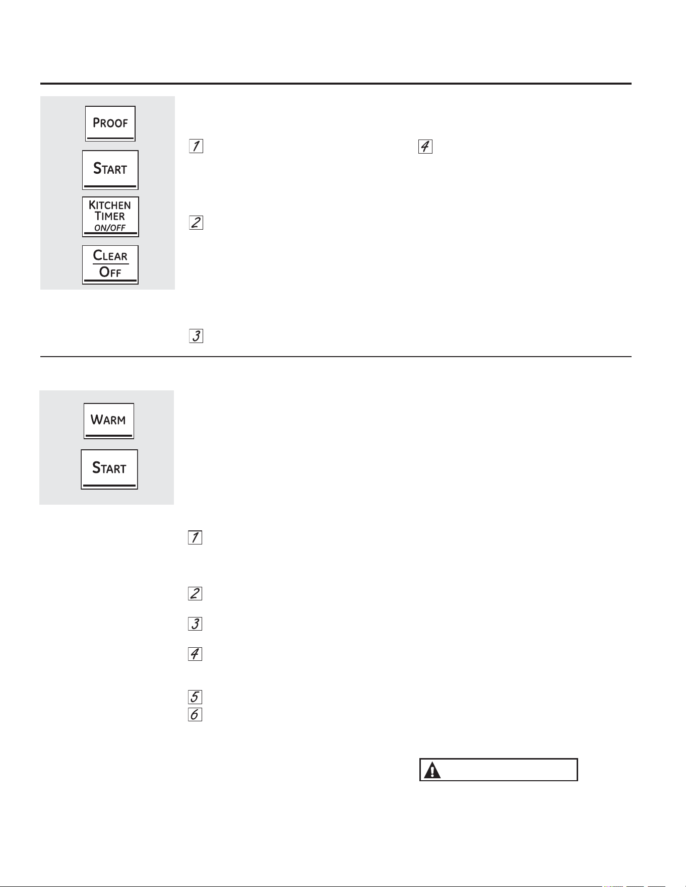
8VRGHODVIXQFLRQHVSDUDUHDOL]DUSUXHEDV\FDOHQWDU
/DFDUDFWHUtVWLFDGHOHXGDGRPDQWLHQHXQPHGLRFDOLHQWH~WLOSDUDOHXGDUSURGXFWRVFRQOHYDGXUD
&yPRFRQILJXUDUHOKRUQRSDUDOHXGDUHQDOJXQRVPRGHORV
&RORTXHODPDVDFXELHUWDHQXQUHFLSLHQWH
GHQWURGHOKRUQRHQODVEDQGHMDV%R&
127$3DUDPHMRUHVUHVXOWDGRVFXEUDODPDVDFRQ
XQSDxRRXQHQYROWRULRSOiVWLFRHQPDQWHFDGRHO
SOiVWLFRSXHGHFRORFDUVHGHEDMRGHOUHFLSLHQWHSDUD
TXHHOYHQWLODGRUGHOKRUQRQRORGHVSODFH
3UHVLRQHHOERWyQ3522)OHXGDU\OXHJRHO
ERWyQ67$57LQLFLDU
(QODSDQWDOODSRGUiYHUVH3U)OHXGDU
/DOX]LQWHUQDGHOKRUQRVHHQFLHQGH\FRQWLQ~D
HQFHQGLGDGXUDQWHHOOHXGDGR
/DFDUDFWHUtVWLFDGHOHXGDGRDXWRPiWLFDPHQWH
EULQGDODWHPSHUDWXUDySWLPDSDUDHOSURFHVR
GHOHXGDGR\SRUORWDQWRQRH[LVWHXQDMXVWHGH
WHPSHUDWXUD
&RQILJXUHHOWHPSRUL]DGRUSDUDHOWLHPSR
GHOHXGDGRPtQLPR
&XDQGRKD\DILQDOL]DGRGHOHXGDUSUHVLRQH
HOERWyQ&/($52))ERUUDUDSDJDGR
3DUDHYLWDUEDMDUODWHPSHUDWXUDGHOKRUQR
\SURORQJDUHOWLHPSRGHOHXGDGRQRDEUDOD
SXHUWDGHOKRUQRLQQHFHVDULDPHQWH
9HULILTXHDQWHVGHWLHPSRORVSURGXFWRV
SDQLILFDGRVSDUDTXHQROHXGHQGHPiV
127$6
1RXWLOLFHHOPRGROHXGDUSDUDFDOHQWDU
DOLPHQWRVRSDUDPDQWHQHUORVFDOLHQWHV
/DWHPSHUDWXUDGHOHXGDGRGHOKRUQRQRHV
ORVXILFLHQWHPHQWHFDOLHQWHSDUDFRQVHUYDU
DOLPHQWRVDWHPSHUDWXUDVVHJXUDV8VHOD
FDUDFWHUtVWLFD:$50FDOLHQWHSDUDPDQWHQHU
ORVDOLPHQWRVFDOLHQWHV
(OOHXGDGRQRIXQFLRQDFXDQGRHOKRUQRWLHQH
XQDWHPSHUDWXUDPD\RUD)&(QOD
SDQWDOODSRGUiYHUVH´+27µFDOLHQWH
(QDOJXQRVPRGHORV
&yPR&RQILJXUDUHO+RUQRSDUD&DOHQWDU
/DIXQFLyQ:$50&DOHQWDUPDQWLHQH
FDOLHQWHVODVFRPLGDVFRFLQDGDV(VWDIXQFLyQ
QRIXHGLVHxDGDSDUDYROYHUDFDOHQWDUFRPLGD
IUtD
3DUDXVDUODIXQFLyQ:$50&DOHQWDUSUHVLRQH
ODWHFOD:$50&DOHQWDU\OXHJRODWHFOD67$57
,QLFLDU
3DUDXVDUODIXQFLyQ:$50&DOHQWDUOXHJR
GHO7LHPSRGH+RUQHDGRR'RUDGRVLJDORV
VLJXLHQWHVSDVRV
3UHVLRQHHOPRGRGHFRFFLyQTXHGHVHH
XVDU+251($'2+251($'20Ò/7,3/(
325&219(&&,Ï1(13$55,//$R
'25$'2325&219(&&,Ï1
3UHVLRQHODVWHFODVQXPpULFDVSDUD
FRQILJXUDUODWHPSHUDWXUDGHOKRUQR
3UHVLRQHODWHFOD&22.,1*7,0(
7HPSRUL]DGRUGH&RFFLyQ
3UHVLRQHODVWHFODVQXPpULFDVSDUD
FRQILJXUDUHOSHUtRGRGHWLHPSRGHFRFFLyQ
GHVHDGR
3UHVLRQHODWHFOD:$50&DOHQWDU
3UHVLRQHODWHFOD67$57,QLFLDU
3DUDTXHËWHPV'XURVTXHGHQ&URFDQWHV
&RORTXHFRPLGDHQSODWRVRFDFHURODVHQOD
SDUWHLQIHULRU
3DUDREWHQHUPHMRUHVUHVXOWDGRVFRORTXH
ODVFRPLGDVHQXQDVRODFDSD1RODV
DPRQWRQH
1RODVFXEUD
&RQWUROHVLHVWiQFURFDQWHVOXHJRGHHQWUH
\PLQXWRV$JUHJXHWLHPSRVHJ~QVHD
QHFHVDULR
127$6,03257$17(6
/DFRPLGDVHGHEHUtDPDQWHQHUFDOLHQWH
HQVXHQYDVHGHFRFFLyQRWUDQVIHULUODDXQ
SODWRFRQSURWHFFLyQWpUPLFDSDUDVHUYLU
3DUDFRPLGDVK~PHGDVFXEUDODVPLVPDV
FRQXQDWDSDVHJXUDSDUDHOKRUQRRSDSHO
GHDOXPLQLR
1RHVQHFHVDULRFXEULUODVFRPLGDVIULWDV
RFURFDQWHVSHURHVSRVLEOHTXHVH
VHTXHQGHPDVLDGRVLVHFDOLHQWDQGXUDQWH
GHPDVLDGRWLHPSR
/DDSHUWXUDUHSHWLGDGHODSXHUWDSHUPLWH
TXHHODLUHFDOLHQWHVDOJD\TXHODFRPLGDVH
HQIUtH
'HMHWUDQVFXUULUXQWLHPSRDGLFLRQDOSDUD
TXHODWHPSHUDWXUDLQWHULRUGHOKRUQRVH
HVWDELOLFHOXHJRGHDJUHJDUORVtWHPV
&RQJUDQGHVFDQWLGDGHVHVSRVLEOHTXHVHD
QHFHVDULRFXEULUDOJXQDVGHODVFRPLGDV
FRFLQDGDV
5HWLUHODVFXFKDUDVSDUDVHUYLUHWFDQWHVGH
FRORFDUUHFLSLHQWHVHQHOKRUQR
1RXVHUHFLSLHQWHVWDSDVQLHQYROWRULRVGH
SOiVWLFR
/RVHQYDVHVWDSDV\HQYROWRULRVGHSOiVWLFRVH
GHUUHWLUiQVLVHFRORFDQHQHOKRUQR(VSRVLEOH
TXHHOSOiVWLFRGHUUHWLGRQRVHSXHGDUHWLUDU\
HVWRQRHVWiFXELHUWRSRUODJDUDQWtD
35(&$8&,Ï1
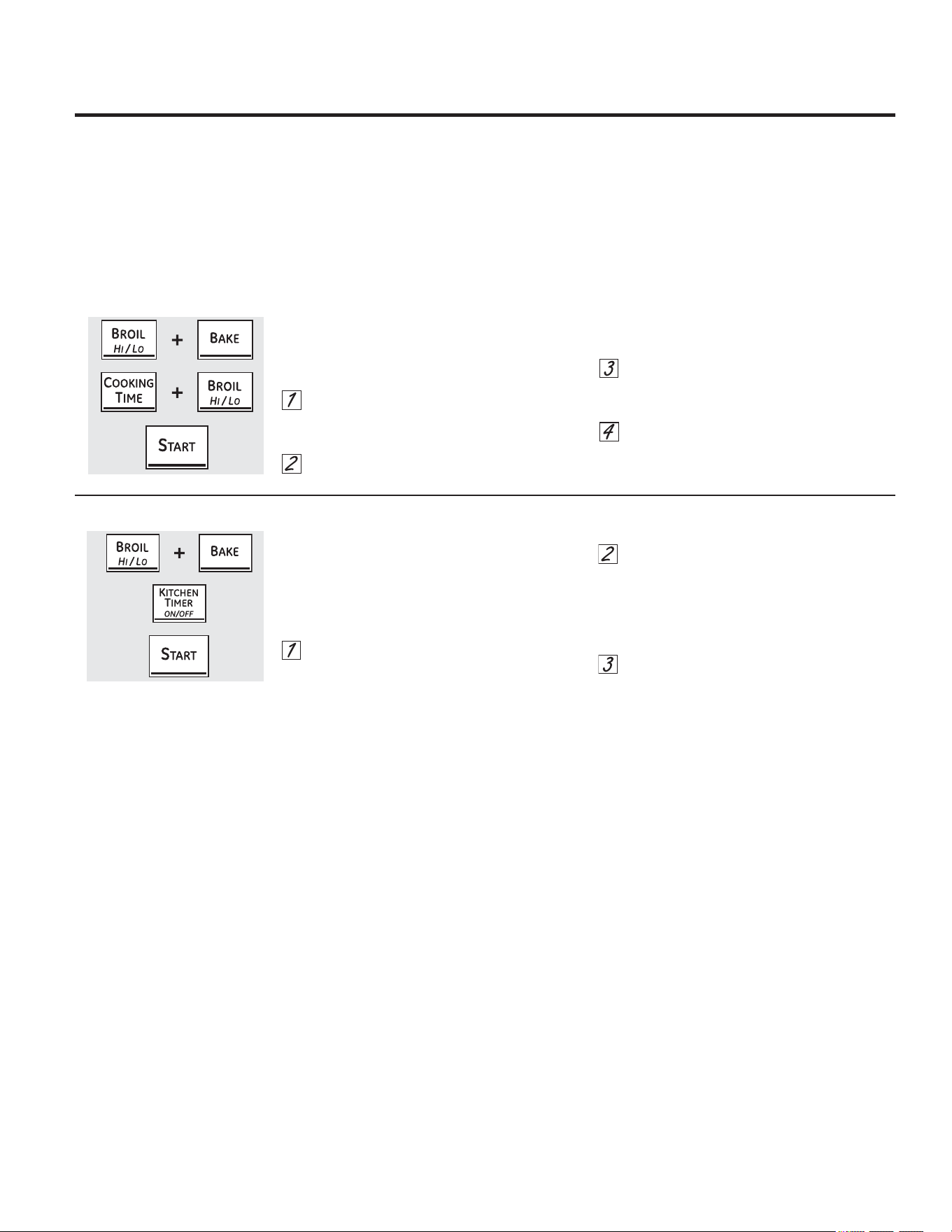
&DUDFWHUtVWLFDVHVSHFLDOHVGHORVFRQWUROHVGHOKRUQR *($SSOLDQFHVFRP
6HOHFFLyQGHWHPSHUDWXUDHQ)DKUHQKHLWR&HOVLXV
6XFRQWUROGHKRUQRHVWiFRQILJXUDGRSDUDXWLOL]DU
ODVVHOHFFLRQHVGHWHPSHUDWXUD)DKUHQKHLWSHUR
SXHGHPRGLILFDUVHSDUDXVDUVHOHFFLRQHVHQ
&HOVLXV
3UHVLRQHORVERWRQHV%52,/+,/2DVDUDOWR
EDMR\%$.(KRUQHDUGHOKRUQRDOPLVPR
WLHPSRKDVWDTXHHQODSDQWDOODSXHGDYHUVH
6)
3UHVLRQHORVERWRQHV&22.,1*7,0(WLHPSR
GHFRFFLyQ\%52,/+,/2DVDUDOWREDMRDO
PLVPRWLHPSR(QODSDQWDOODSRGUiYHUVH)
)DKUHQKHLW
3UHVLRQHORVERWRQHV&22.,1*7,0(WLHPSR
GHFRFFLyQ\%52,/+,/2DVDUDOWREDMRGH
QXHYRDOPLVPRWLHPSR(QODSDQWDOODSRGUi
YHUVH&&HOVLXV
3UHVLRQHHOERWyQ67$57LQLFLDU
6HxDOHVVRQRUDVDOILQDOL]DUXQFLFORFRQWHPSRUL]DGRU
$OILQDOL]DUXQFLFORFRQWHPSRUL]DGRUVHHVFXFKDQ
SLWLGRVFRUWRVVHJXLGRVSRUXQSLWLGRFDGD
VHJXQGRVKDVWDTXHVHSUHVLRQHHOERWyQ&/($5
2))ERUUDUDSDJDGR(VWHSLWLGRFRQWLQXRGH
VHJXQGRVSXHGHFDQFHODUVH
3DUDFDQFHODUHOSLWLGRFRQWLQXRGHVHJXQGRV
3UHVLRQHORVERWRQHV%52,/+,/2DVDUDOWR
EDMR\%$.(KRUQHDUGHOKRUQRVXSHULRUDO
PLVPRWLHPSRKDVWDTXHHQODSDQWDOOD
SXHGDYHUVH6)
3UHVLRQHHOERWyQ.,7&+(17,0(5
7HPSRUL]DGRUGHOD&RFLQD/DSDQWDOOD
PXHVWUD&217,%((3SLWLGRFRQWLQXR
3UHVLRQHHOERWyQ.,7&+(17,0(5
7HPSRUL]DGRUGHOD&RFLQDGHQXHYR/D
SDQWDOODPXHVWUD6,1*/(%((3SLWLGR~QLFR
(VWRFDQFHODHOSLWLGRFDGDVHJXQGRV
3UHVLRQHHOERWyQ67$57LQLFLDU
/RVQXHYRVFRQWUROHVFRQERWRQHVGHWRTXHFXHQWDQFRQFDUDFWHUtVWLFDVDGLFLRQDOHV/DVVLJXLHQWHVVRQODVFDUDFWHUtVWLFDV
\ODPDQHUDHQTXHXVWHGSXHGHDFWLYDUODV
/RVPRGRVGHFDUDFWHUtVWLFDVHVSHFLDOHVVyORSXHGHQDFWLYDUVHPLHQWUDVODSDQWDOODPXHVWUDODKRUD6HFRQVHUYDQHQOD
PHPRULDGHORVFRQWUROHVKDVWDTXHVHUHSLWDQORVSDVRV
3DUDLQJUHVDUXQDIXQFLyQHVSHFLDOSDUDFDGDKRUQRSULPHURGHEHUiSUHVLRQDUODVWHFODV%52,/+,/2$VDU$OWR%DMRDO
PLVPRWLHPSR
&XDQGRODSDQWDOODPXHVWUDVXRSFLyQSUHVLRQHHOERWyQ67$57LQLFLDU/DVFDUDFWHUtVWLFDVHVSHFLDOHVVHFRQVHUYDUiQHQOD
PHPRULDGHVSXpVGHXQFRUWHGHHQHUJtDFRQH[FHSFLyQGHO6DEEDWKTXHGHEHUHFRQILJXUDUVH
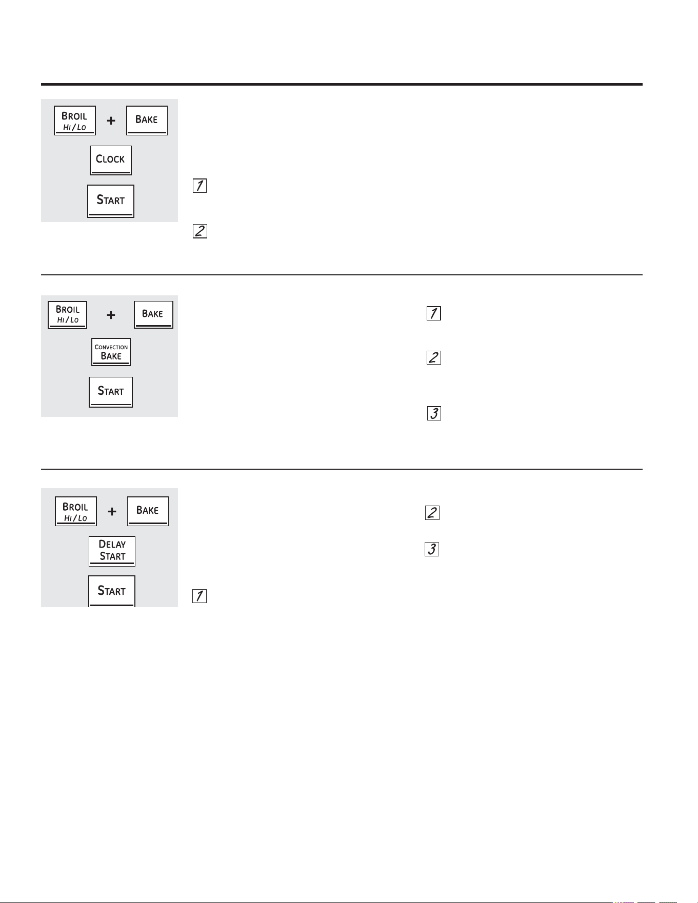
&DUDFWHUtVWLFDVHVSHFLDOHVGHORVFRQWUROHVGHOKRUQR
&RQYHUVLyQ$XWRPiWLFDGH5HFHWDV
HQDOJXQRVPRGHORV
$OXVDUHOKRUQHDGRSRUFRQYHFFLyQODIXQFLyQGH
&RQYHUVLyQ$XWR5HFLSH
SRGUiDXWRPiWLFDPHQWH
FRQYHUWLUWHPSHUDWXUDVGHKRUQHDGRUHJXODU
LQJUHVDGDVDWHPSHUDWXUDVGHKRUQHDGRSRU
FRQYHFFLyQ/DSDQWDOODPRVWUDUiODWHPSHUDWXUD
FRQYHUWLGDUHGXFLGD3RUHMHPSORVLXVWHGLQJUHVD
XQDWHPSHUDWXUDUHJXODUGHSDUDXQDUHFHWD\
SUHVLRQDODWHFOD67$57,QLFLDUODSDQWDOODPRVWUDUi
&21&RQYHUWLU\ODWHPSHUDWXUDFRQYHUWLGDGH)
3DUDDFWLYDURGHVDFWLYDUODIXQFLyQ
3UHVLRQHORVERWRQHV%$.(KRUQHDU\%52,/
+,/2DVDUDOWREDMRGHOKRUQRDOPLVPR
WLHPSRKDVWDTXHHQODSDQWDOODSXHGDYHUVH
6)
3UHVLRQHODWHFOD&219(&7,21%$.(
+RUQHDGRSRU&RQYHFFLyQKDVWDTXHOD
SDQWDOODPXHVWUH&2121&RQYHUVLyQ
(QFHQGLGDR&212))&RQYHUVLyQ$SDJDGD
VHJ~QVHGHVHH
3UHVLRQHHOERWyQ67$57LQLFLDU
KRUDVKRUDVREORTXHRGHOUHORM
6XVFRQWUROHVHVWiQFRQILJXUDGRVSDUDXVDUXQUHORM
GHKRUDV
6LSUHILHUHWHQHUXQUHORMGHHVWLORPLOLWDUGHKRUDV
RDQXODUODYLVXDOL]DFLyQGHOUHORMVLJDORVVLJXLHQWHV
SDVRV
3UHVLRQHORVERWRQHV%52,/+,/2DVDUDOWR
EDMR\%$.(KRUQHDUGHOKRUQRDOPLVPR
WLHPSRKDVWDTXHHQODSDQWDOODSXHGDYHUVH
6)
3UHVLRQHHOERWyQ&/2&.UHORMXQDYH](QOD
SDQWDOODSRGUiYHUVHKU6LHVWDHVODRSFLyQ
TXHGHVHDSUHVLRQHHOERWyQ67$57LQLFLDU
3UHVLRQHHOERWyQ&/2&.UHORMGHQXHYRSDUD
FDPELDUDOUHORMHVWLORPLOLWDUGHKRUDV(QOD
SDQWDOODSRGUiYHUVHKU6LHVWDHVODRSFLyQTXH
GHVHDSUHVLRQHHOERWyQ67$57LQLFLDU
3UHVLRQHHOERWyQ&/2&.UHORMGHQXHYRSDUDDQXODU
ODYLVXDOL]DFLyQGHOUHORM(QODSDQWDOODSRGUiYHUVH
2))DSDJDGR6LHVWDHVODRSFLyQTXHGHVHD
SUHVLRQHHOERWyQ67$57LQLFLDU
127$6LHOUHORMVHHQFXHQWUDHQHOPRGRVLQ
YLVXDOL]DFLyQXVWHGQRSRGUiXWLOL]DUODIXQFLyQGH
LQLFLRUHWDUGDGR
$SDJDGROXHJRGHKRUDV
&RQHVWDRSFLyQHQFDVRGHGHMDUVHHOKRUQRHQFHQGLGR
DFFLGHQWDOPHQWHHOFRQWUROORDSDJDHQIRUPD
DXWRPiWLFDOXHJRGHKRUDVGXUDQWHIXQFLRQHVGH
KRUQHDGRRGHVSXpVGHKRUDVGXUDQWHODIXQFLyQGH
DVDGR
6LGHVHDDSDJDU2))HVWDIXQFLyQVLJDORVSDVRV
VLJXLHQWHV
3UHVLRQHORVERWRQHV%52,/+,/2DVDUDOWREDMR\
%$.(KRUQHDUGHOKRUQRDOPLVPRWLHPSRKDVWD
TXHHQODSDQWDOODSXHGDYHUVH6)
3UHVLRQHHOERWyQ'(/$<67$57LQLFLRUHWDUGDGR
KDVWDTXHDSDUH]FDQRVKGQQRDSDJDGRHQOD
SDQWDOOD
3UHVLRQHHOERWyQ67$57LQLFLDUSDUDDFWLYDUOD
FDUDFWHUtVWLFDGHQRDSDJDGR\GHMDUHOFRQWURO
FRQILJXUDGRHQHVWHPRGRGHFDUDFWHUtVWLFDV
HVSHFLDOHV
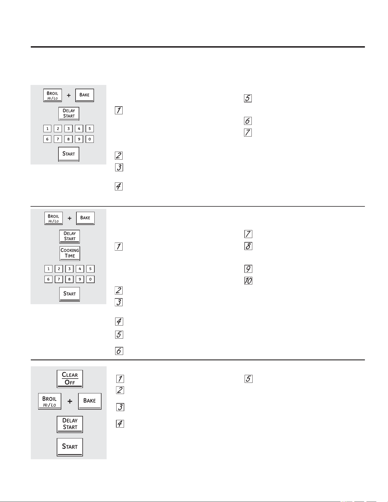
&yPRXVDUODIXQFLyQ6DEEDWK
'LVHxDGDSDUDXWLOL]DUVHGXUDQWHHO6DEEDWKXRWUDV)LHVWDV-XGtDVHQDOJXQRVPRGHORV
*($SSOLDQFHVFRP
3UHVLRQHHOERWyQ&/($52))ERUUDUDSDJDGR
6LHOKRUQRHVWiFRFLQDQGRHVSHUHXQSHUtRGR
DOHDWRULRGHDSUR[LPDGDPHQWHVHJXQGRVD
PLQXWRKDVWDTXHVyORDSDUH]FDHQODSDQWDOOD
3UHVLRQH\VRVWHQJDORVERWRQHV%52,/+,/2
DVDUDOWREDMR\%$.(KRUQHDUDOPLVPRWLHPSR
KDVWDTXHHQODSDQWDOODSXHGDYHUVH6)
3UHVLRQHHOERWyQ'(/$<67$57LQLFLRUHWDUGDGR
KDVWDTXHVKGQRQRVKGQDSDUH]FDQHQOD
SDQWDOOD
(OLMDVKGQLQGLFDQGRTXHHOKRUQRVHDSDJDUi
DXWRPiWLFDPHQWHGHVSXpVGHKRUDVRQR
VKGQLQGLFDQGRTXHHOKRUQRQRVHDSDJDUi
DXWRPiWLFDPHQWHGHVSXpVGHKRUDV
3UHVLRQH67$57LQLFLDUFXDQGRODRSFLyQGHVHDGD
DSDUHFHHQODSDQWDOODVKGQRQRVKGQ
127$(QFDVRGHFRUWHGHHQHUJtDFRQODIXQFLyQ
GH6DEEDWKDFWLYDGDGLFKDIXQFLyQVHDSDJDUi
DXWRPiWLFDPHQWHD~QFXDQGRYXHOYDODHQHUJtD(O
FRQWUROGHOKRUQRGHEHYROYHUDFRQILJXUDUVH$OJXQRV
PRGHORVFRQWLQXDUiQHOPRGR6DEEDWKVLQHPEDUJRVL
VHDEUHODSXHUWDVHDFWLYDUiODOX]GHOKRUQR
/DIXQFLyQ6DEEDWKVRODPHQWHSXHGHXWLOL]DUVHSDUDKRUQHDUURVWL]DU1RHVSRVLEOHXWLOL]DUODSDUDFRQYHFFLyQDVDGRDXWROLPSLH]DRFRFFLyQFRQ
LQLFLRUHWDUGDGR
127$/DOX]LQWHULRUGHOKRUQRVHHQFLHQGHDXWRPiWLFDPHQWHHQDOJXQRVPRGHORVFXDQGRVHDEUHODSXHUWD\VHDSDJDFXDQGRVHODFLHUUD3XHGH
TXLWDUVHODERPELOODGHOX]9HUODVHFFLyQGH5HHPSOD]RGHERPELOODGHOX](QORVPRGHORVFRQLQWHUUXSWRUGHOX]HQHOSDQHOGHFRQWUROODOX]GHO
KRUQRSXHGHHQFHQGHUVH\GHMDUVHDVt
$VHJ~UHVHGHTXHHOUHORMPXHVWUHODKRUDFRUUHFWD\TXH
HOKRUQRHVWpDSDJDGR
3UHVLRQH\VRVWHQJDORVERWRQHV%52,/+,/2
DVDUDOWREDMR\%$.(KRUQHDUDOPLVPRWLHPSR
KDVWDTXHHQODSDQWDOODSXHGDYHUVH6)
127$6LHQODSDQWDOODDSDUHFHQ%DNHKRUQHDUR
%URLODVDUORVERWRQHV%52,/+,/2DVDUDOWR
EDMR\%$.(KRUQHDUQRVHSUHVLRQDURQDOPLVPR
WLHPSR3UHVLRQHHOERWyQ&/($52))ERUUDU
DSDJDGR\FRPLHQFHGHQXHYR
3UHVLRQHHOERWyQ'(/$<67$57LQLFLRUHWDUGDGR
KDVWDTXHDSDUH]FD6$EE$W+HQODSDQWDOOD
3UHVLRQHHOERWyQ67$57LQLFLDU\DSDUHFHUiHQ
ODSDQWDOOD
(OKRUQRVHHQFXHQWUDDKRUDHQHO
PRGR6DEiWLFR
3UHVLRQHHOERWyQ%$.(KRUQHDU1RVHGDUiXQD
VHxDO
0HGLDQWHODVDOPRKDGLOODVQXPpULFDVLQJUHVHOD
WHPSHUDWXUDGHVHDGDHQWUH)&\)
&1RVHGDUiQLQJXQDVHxDORWHPSHUDWXUD
1RKD\XQDWHPSHUDWXUDSUHGHWHUPLQDGD
3UHVLRQHHOERWyQ67$57LQLFLDU
'HVSXpVGHXQSHUtRGRDOHDWRULRGH
DSUR[LPDGDPHQWHVHJXQGRVDPLQXWR
DSDUHFHUiHQODSDQWDOODLQGLFDQGRTXHHOKRUQR
HVWiKRUQHDQGRURVWL]DQGR6LQRDSDUHFHHQ
ODSDQWDOODFRPLHQFHGHQXHYRHQHOSDVR
3DUDDMXVWDUODWHPSHUDWXUDGHOKRUQRSUHVLRQHHOERWyQ
%$.(KRUQHDULQJUHVHODQXHYDWHPSHUDWXUDXVDQGR
ODVDOPRKDGLOODVQXPpULFDV\SUHVLRQHHOERWyQ67$57
LQLFLDU
127$/RVERWRQHV&/($52))ERUUDUDSDJDGR\
&22.,1*7,0(WLHPSRGHFRFFLyQVHHQFXHQWUDQ
DFWLYRVGXUDQWHODIXQFLyQ6DEEDWK
&yPRGHVDFWLYDUODIXQFLyQ6DEEDWK
&XDQGRODSDQWDOODPXHVWUD
HOKRUQRHVWiFRQILJXUDGRSDUD
6DEEDWK&XDQGRODSDQWDOOD
PXHVWUDHOKRUQRHVWi
KRUQHDQGRURVWL]DQGR
&yPRFRQILJXUDUKRUQHDGRURVWL]DGRFRQWHPSRUL]DGRU,QLFLRLQPHGLDWR
\DSDJDGRDXWRPiWLFR
$VHJ~UHVHGHTXHHOUHORMPXHVWUHODKRUDFRUUHFWD
\TXHHOKRUQRHVWpDSDJDGR
3UHVLRQH\VRVWHQJDORVERWRQHV%52,/+,/2
DVDUDOWREDMR\%$.(KRUQHDUDOPLVPRWLHPSR
KDVWDTXHHQODSDQWDOODSXHGDYHUVH6)
127$6LHQODSDQWDOODDSDUHFHQ%DNHKRUQHDUR
%URLODVDUORVERWRQHV%52,/+,/2DVDUDOWR
EDMR\%$.(KRUQHDUQRVHSUHVLRQDURQDOPLVPR
WLHPSR3UHVLRQHHOERWyQ&/($52))ERUUDU
DSDJDGR\FRPLHQFHGHQXHYR
3UHVLRQHHOERWyQ'(/$<67$57LQLFLRUHWDUGDGR
KDVWDTXHDSDUH]FD6$EE$W+HQODSDQWDOOD
3UHVLRQHHOERWyQ67$57LQLFLDU\DSDUHFHUiHQ
ODSDQWDOOD(OKRUQRHVWiDKRUDHQHOPRGR
6DEEDWK
3UHVLRQHHOERWyQ&22.,1*7,0(WLHPSRGH
FRFFLyQ1RVHGDUiXQDVHxDO
3UHVLRQHODVDOPRKDGLOODVQXPpULFDVSDUD
FRQILJXUDUHOWLHPSRGHVHDGRGHFRFFLyQHQWUH
PLQXWR\KRUDV\PLQXWRV
3UHVLRQHHOERWyQ67$57LQLFLDU
3UHVLRQHHOERWyQ%$.(KRUQHDU1RVHGDUiXQD
VHxDO
3UHVLRQHODVDOPRKDGLOODVQXPpULFDVSDUD
FRQILJXUDUODWHPSHUDWXUDGHVHDGD1RVHGDUi
QLQJXQDVHxDORWHPSHUDWXUD1RKD\XQD
WHPSHUDWXUDSUHGHWHUPLQDGD
3UHVLRQHHOERWyQ67$57LQLFLDU
'HVSXpVGHXQSHUtRGRDOHDWRULRGH
DSUR[LPDGDPHQWHVHJXQGRVDPLQXWR
DSDUHFHUiHQODSDQWDOODLQGLFDQGRTXHHOKRUQR
HVWiKRUQHDQGRURVWL]DQGR6LQRDSDUHFHHQ
ODSDQWDOODFRPLHQFHGHQXHYRHQHOSDVR
3DUDDMXVWDUODWHPSHUDWXUDGHOKRUQRSUHVLRQHHOERWyQ
%$.(KRUQHDULQJUHVHODQXHYDWHPSHUDWXUDXVDQGR
ODVDOPRKDGLOODVQXPpULFDV\SUHVLRQHHOERWyQ67$57
LQLFLDU
&XDQGRVHKD\DWHUPLQDGRODFRFFLyQODSDQWDOOD
FDPELDUiGHD\DSDUHFHUiLQGLFDQGRTXH
HOKRUQRVHKDDSDJDGR2))SHURVLJXHFRQILJXUDGRHQ
6DEEDWK5HWLUHORVDOLPHQWRVGHOKRUQR
&XDQGRODSDQWDOODPXHVWUD
HOKRUQRHVWiFRQILJXUDGRSDUD
6DEEDWK&XDQGRODSDQWDOOD
PXHVWUDHOKRUQRHVWi
KRUQHDQGRURVWL]DQGR

1RXWLOLFHDOPRKDGLOODVGHDFHURSRUTXHUD\DQ
ODVXSHUILFLH
3DUDOLPSLDUODVXSHUILFLHGHDFHURLQR[LGDEOH
XWLOLFHDJXDWLELDMDERQRVDRXQOLPSLDGRUR
OXVWUDGRUGHDFHURLQR[LGDEOH6LHPSUHOLPSLH
ODVXSHUILFLHHQGLUHFFLyQGHODYHWD6LJDODV
LQVWUXFFLRQHVGHOSURGXFWRSDUDOLPSLDUOD
VXSHUILFLHGHDFHURLQR[LGDEOH
3DUDFRQVXOWDUVREUHODFRPSUDGHOLPSLDGRUHV
ROXVWUDGRUHVGHDSDUDWRVGHDFHURLQR[LGDEOHR
SDUDHQFRQWUDUODXELFDFLyQGHOGLVWULEXLGRUPiV
FHUFDQRDVXGRPLFLOLROODPHDQXHVWURQ~PHUR
JUDWXLWR
&HQWURQDFLRQDOGHUHSXHVWRV
*($SSOLDQFHVFRP
6XSHUILFLHVGHDFHURLQR[LGDEOHHQDOJXQRVPRGHORV
$VHJ~UHVHGHTXHWRGRVORVFRQWUROHVHVWpQDSDJDGRV\TXHODVVXSHUILFLHVHVWpQIUtDVDQWHVGHOLPSLDUFXDOTXLHUSDUWHGHODFRFLQD
6LVHTXLWDODFRFLQDSDUDHIHFWXDUXQDOLPSLH]DUHSDUDFLRQHVR
FXDOTXLHURWUDUD]yQYHULILTXHTXH
HOGLVSRVLWLYRDQWLYROFDGXUDVVHFRORTXHGHPDQHUDDGHFXDGD
FXDQGRYXHOYDDLQVWDODUVHODFRFLQD
6LQRWRPDHVWDSUHFDXFLyQODFRFLQDSXHGHYROFDUVH
\SURYRFDUOHVLRQHV
3DQHOGHFRQWURO
6LDVtORGHVHDSXHGHGHVDFWLYDUORVERWRQHVGHWRTXH
DQWHVGHODOLPSLH]D
9HUODLQIRUPDFLyQVREUH%ORTXHRGHFRQWUROHVHQOD
VHFFLyQ&yPRXVDUHOUHORMHOWHPSRUL]DGRU\HOEORTXHR
GHFRQWUROHVGHHVWHPDQXDO
/LPSLHORVGHUUDPHVFRQXQSDxRK~PHGR
7DPELpQSXHGHXWLOL]DUXQOLPSLDGRUGHYLGULRV
4XLWHVXFLHGDGHVPiVUHEHOGHVFRQDJXDWLELD
MDERQRVD1RXWLOLFHDEUDVLYRVGHQLQJXQDFODVH
9XHOYDDDFWLYDUORVERWRQHVGHWRTXHGHVSXpVGHOD
OLPSLH]D
6XSHUILFLHVSLQWDGDV
/DVVXSHUILFLHVSLQWDGDVLQFOX\HQORVODGRVGHODFRFLQD
\ODSXHUWDODSDUWHVXSHULRUGHOSDQHOGHFRQWURO\HO
IUHQWHGHOFDMyQ/tPSLHODVFRQMDEyQ\DJXDRFRQXQD
VROXFLyQGHDJXD\YLQDJUH
1RXWLOLFHOLPSLDGRUHVGHKRUQRFRPHUFLDOHVSROYRV
OLPSLDGRUHVHVSRQMLOODVGHDFHURRDEUDVLYRVSRWHQWHV
VREUHFXDOTXLHUVXSHUILFLHSLQWDGD
&yPRTXLWDUHOHQYROWRULRGHSURWHFFLyQ\ODFLQWDGHHPEDODMH
&RQFXLGDGRWRPHXQDSXQWDGHOHQYROWRULR
GHSURWHFFLyQFRQVXVGHGRV\OHQWDPHQWHTXtWHORGHOD
VXSHUILFLHGHODSDUDWR1RXVHHOHPHQWRVILORVRVSDUD
TXLWDUHOHQYROWRULR4XLWHWRGRHOHQYROWRULRDQWHVGH
XVDUHODSDUDWRSRUSULPHUDYH]
3DUDDVHJXUDUVHGHQRGDxDUHODFDEDGRGHOSURGXFWR
ODPHMRUIRUPDGHTXLWDUHOSHJDPHQWRGHODFLQWDGH
HPSDTXHGHORVDSDUDWRVQXHYRVFRQVLVWHHQDSOLFDU
GHWHUJHQWHSDUDYDMLOODVOtTXLGR$SOLTXHFRQXQSDxR
VXDYH\GHMHUHPRMDU
127$'HEHUHWLUDUVHHODGKHVLYRGHWRGDVODVSDUWHV
6LVHFDOLHQWDVHUiLPSRVLEOHGHTXLWDU
3HULOODVGHFRQWURO
/DVSHULOODVGHFRQWUROVHSXHGHQUHWLUDUSDUDIDFLOLWDU
ODOLPSLH]D$VHJ~UHVHGHTXHODVSHULOODVHVWpQHQODV
SRVLFLRQHV2))$SDJDGR\HPSXMHODVPLVPDVGHVGH
ORVVRSRUWHVGHIRUPDGHUHFKDSDUDVXOLPSLH]D
9HULILTXHTXHODVSHULOODVHVWpQHQODSRVLFLyQ2))
DSDJDGR\ViTXHODVGHORVYiVWDJRVSDUDODOLPSLH]D
/DVSHULOODVSXHGHQOLPSLDUVHHQHOODYDYDMLOODVR
WDPELpQSXHGHQODYDUVHFRQMDEyQ\DJXD$VHJ~UHVH
GHTXHODSDUWHLQWHUQDGHODVSHULOODVHVWpVHFDDQWHV
GHYROYHUDFRORFDUVH
9XHOYDDFRORFDUODVSHULOODVHQODSRVLFLyQ2))
DSDJDGRSDUDDVHJXUDUXQDFRORFDFLyQ
FRUUHFWD
(VWXIDGHHVPDOWHGHSRUFHODQDHQDOJXQRVPRGHORV
(ODFDEDGRGHHVPDOWHGHSRUFHODQDHV
UHVLVWHQWHSHURSXHGHURPSHUVHVLVHXWLOL]D
LQFRUUHFWDPHQWH(VWHDFDEDGRHVUHVLVWHQWH
DOiFLGR6LQHPEDUJRQRGHEHSHUPLWLUVHTXH
DOJXQRVDOLPHQWRViFLGRVTXH
VHGHUUDPDQFRPRMXJRVGHIUXWDWRPDWHR
YLQDJUHSHUPDQH]FDQHQHODFDEDGR
6LVHGHUUDPDQiFLGRVHQODHVWXIDPLHQWUDVHVWi
FDOLHQWHXWLOLFHXQDWRDOODGHSDSHORXQSDxR
VHFRVSDUDOLPSLDUORHQHOPRPHQWR&XDQGR
ODVXSHUILFLHVHKD\DHQIULDGROLPSLHFRQDJXD
MDERQRVD(QMXDJXHELHQ
(QHOFDVRGHRWURVGHUUDPHVFRPRVDOSLFDGXUDV
GHJUDVDHWFOLPSLHFRQDJXDMDERQRVDRSROYRV
OLPSLDGRUHVFXDQGRODVXSHUILFLHVHKD\DHQIULDGR
(QMXDJXHELHQ3XODFRQXQSDxRVHFR
&XLGDGR\OLPSLH]DGHODFRFLQD
$'9(57(1&,$
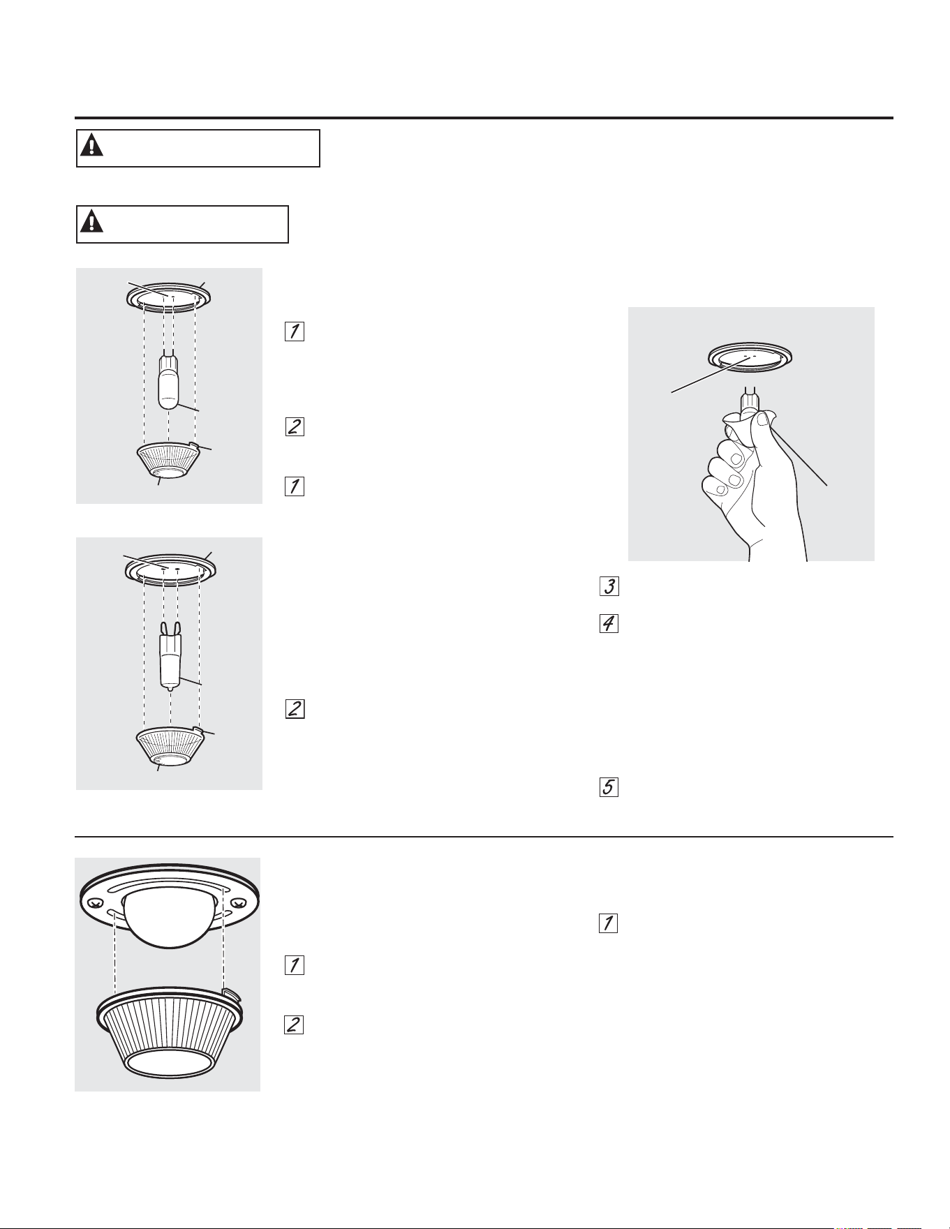
5HHPSOD]RGHODERPELOODGHOKRUQRHQDOJXQRVPRGHORV
3DUDUHWLUDU
*LUHODFXELHUWDGHYLGULRHQVHQWLGRFRQWUDULR
DODVPDQHFLOODVGHOUHORMGHYXHOWDKDVWD
TXHODVOHQJHWDVGHODFXELHUWDGHYLGULR
OLEHUHQORVVXUFRVGHOSRUWDOiPSDUDV
&RORFDUVHJXDQWHVGHOiWH[SXHGHEULQGDU
XQPHMRUDJDUUH
8WLOL]DQGRJXDQWHVRXQSDxRVHFRUHPXHYD
ODERPELOODMDOiQGRODHQOtQHDUHFWD
3DUDUHHPSOD]DU
8WLOLFHXQDQXHYDERPELOODKDOyJHQDGH
YROWLRVQRH[FHGDYDWLRV
5HHPSODFHODOiPSDUDGHOX]FRQHOPLVPR
WLSRGHOiPSDUDTXHVHUHWLUy(QVXPRGHOR
FRUUHVSRQGHUiXQRGHORVGRVWLSRVTXH
ILJXUDQDODL]TXLHUGD3DUDGHWHUPLQDUFXiO
HVODOiPSDUDFRUUHFWDFRQWUROHODV
WHUPLQDOHVGHODOiPSDUD/DVOiPSDUDVFRQ
WHUPLQDOHVFRQFODYLMDVUHFWDVVRQOiPSDUDV
GH*/DVOiPSDUDVFRQWHUPLQDOHVFRQ
FODYLMDVFRQFXUYDVVRQOiPSDUDVGH*1R
ODVLQWHUFDPELH$VHJ~UHVHDOUHHPSOD]DUOD
OiPSDUDTXHVHDGHYROWVRYROWV
12GHYROWV
8WLOL]DQGRJXDQWHVRXQSDxRVHFRUHPXHYD
ODERPELOODGHVXSDTXHWH1RWRTXHOD
ERPELOODFRQORVGHGRVGHVQXGRV(ODFHLWH
SDUDSLHOGDxDUiODOiPSDUD\DFRUWDUiVX
WLHPSRGHGXUDFLyQ
(PSXMHODERPELOODHQOtQHDUHFWDGHQWURGHO
UHFHSWiFXORKDVWDHOWRSH
&RORTXHODVOHQJHWDVGHODFXELHUWDGH
YLGULRGHQWURGHORVVXUFRVGHO
SRUWDOiPSDUDV*LUHODFXELHUWDGHYLGULRHQ
VHQWLGRGHODVPDQHFLOODVGHOUHORMGH
YXHOWD
3DUDXQDPHMRULOXPLQDFLyQGHQWURGHO
KRUQROLPSLHIUHFXHQWHPHQWHODFXELHUWD
GHYLGULRXWLOL]DQGRXQSDxRK~PHGR(VWR
GHEHUtDKDFHUVHFXDQGRHOKRUQRHVWi
FRPSOHWDPHQWHIUtR
&RQHFWHQXHYDPHQWHHOVXPLQLVWURHOpFWULFR
DOKRUQR
%RPELOOD
GH*
3RUWDOiPSDUD
/HQJHWD
&XELHUWDGHYLGULR
5HFHSWiFXOR
8VH
JXDQWHV
RXQ
SDxR
5HFHSWiFXOR
%RPELOOD
GH*
3RUWDOiPSDUD
/HQJHWD
&XELHUWDGHYLGULR
5HFHSWiFXOR
HQDOJXQDVPRGHORV
HQDOJXQDVPRGHORV
3(/,*52'('(6&$5*$(/e&75,&$248(0$'85$6$QWHVGHUHHPSOD]DUODERPELOOD
GHOKRUQRGHVFRQHFWHODDOLPHQWDFLyQGHHQHUJtDDOKRUQRGHVGHHOSDQHOSULQFLSDO
GHIXVLEOHVRGHOLQWHUUXSWRUGHFLUFXLWRV1RKDFHUORSXHGHSURYRFDUXQDGHVFDUJD
HOpFWULFDRXQDTXHPDGXUD
$'9(57(1&,$
3(/,*52'(48(0$'85$6/DWDSDGHYLGULR\ODOiPSDUDGHOX]VHGHEHUiQUHWLUDUFXDQGR
HVWpQIUtDV7RFDUHOYLGULRFDOLHQWHVLQSURWHFFLyQHQODVPDQRVRFRQXQWUDSRK~PHGR
SXHGHRFDVLRQDUTXHPDGXUDV
35(&$8&,Ï1
*($SSOLDQFHVFRP
5HHPSOD]RGHODERPELOODGHOKRUQR
HQDOJXQRVPRGHORV
9HULILTXHTXHODWDSDGHODOiPSDUD\OD
ERPELOODVHKD\DQHQIULDGRSRUFRPSOHWR
3DUDTXLWDUODWDSD
+DJDJLUDUODOHQWHHQóGHYXHOWDHQ
VHQWLGRDQWLKRUDULRSDUDTXLWDUOD
1RTXLWHQLQJ~QWRUQLOORSDUDVDFDUODWDSD
&RORTXHXQDERPELOODGHYDWLRVRXQD
ERPELOODKDOyJHQDGHGRVHVSLJDVVHJ~Q
FRUUHVSRQGD
3DUDYROYHUDFRORFDUODWDSD
$OLQHHODVOHQJHWDVGHODOHQWHIUHQWHDODV
OHQJHWDVGHODFDUFDVD\JLUHHQVHQWLGR
KRUDULRSDUDWUDEDU
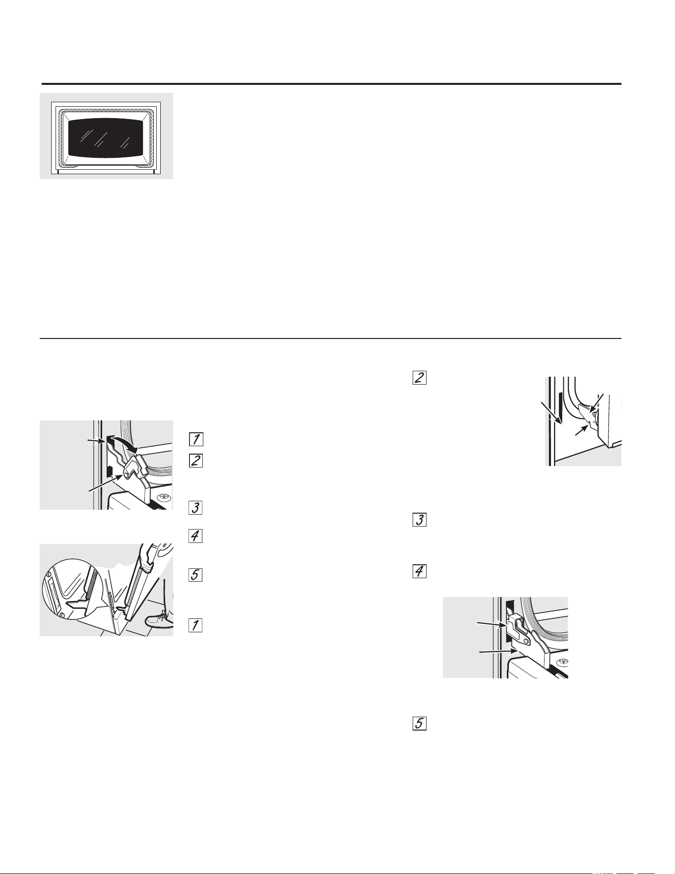
&XLGDGR\OLPSLH]DGHODFRFLQD
/DSXHUWDHVPX\SHVDGD7HQJDFXLGDGRDOTXLWDU\
OHYDQWDUODSXHUWD
1ROHYDQWHODSXHUWDGHODPDQLMD
3DUDTXLWDUODSXHUWD
$EUDODSXHUWDSRUFRPSOHWR
3UHVLRQHODVWUDEDVGHODELVDJUDKDFLDDEDMRHQ
GLUHFFLyQGHOPDUFRGHODSXHUWDKDVWD
GHVWUDEDUODV3XHGHQHFHVLWDUVHXQDKHUUDPLHQWD
FRPRXQGHVWRUQLOODGRUSODQRSHTXHxR
7RPHFRQILUPH]DDPERVODGRVGHODSXHUWDGHOD
SDUWHVXSHULRU
&LHUUHODSXHUWDKDVWDODSRVLFLyQGHUHPRFLyQGH
SXHUWDTXHHVDPLWDGGHFDPLQRHQWUHOD
SRVLFLyQGHDVDGR\ODSXHUWDFHUUDGD
/HYDQWHODSXHUWDKDVWDTXHHOEUD]RGHOD
ELVDJUDKD\DVDOLGRGHODUDQXUD
3DUDYROYHUDFRORFDUODSXHUWD
7RPHFRQILUPH]DDPERVODGRVGHODSXHUWDGHOD
SDUWHVXSHULRU
&RQODSXHUWDHQ
HOPLVPRiQJXOR
GHODSRVLFLyQGH
UHPRFLyQ
LQWURGX]FD
ODPXHVFDGHOEUD]R
GHODELVDJUDGHQWUR
GHOH[WUHPRLQIHULRUGHOD
UDQXUDGHODELVDJUD/D
UDQXUDGHOEUD]RGHOD
ELVDJUDGHEH
HVWDUELHQFRORFDGDHQODSDUWHLQIHULRU
GHODUDQXUD
$EUDODSXHUWDSRUFRPSOHWR6LODSXHUWD
QRVHDEUHSRUFRPSOHWRODPXHVFDQRHVWiELHQ
FRORFDGDHQHOH[WUHPRLQIHULRUGH
ODUDQXUD
3UHVLRQHODVWUDEDVGHODELVDJUDKDFLDDUULED
FRQWUDHOPDUFRIURQWDOGHODFDYLGDGGHOKRUQR
KDVWDDOFDQ]DUODSRVLFLyQGHEORTXHR
&LHUUHODSXHUWDGHOKRUQR
3XHUWDGHOKRUQRGHVPRQWDEOHHQDOJXQRVPRGHORV
/DMXQWDHVWiGLVHxDGDFRQXQHVSDFLR
HQODSDUWHLQIHULRUSDUDSHUPLWLUXQD
DGHFXDGDFLUFXODFLyQGHDLUH
1RIURWHROLPSLHODMXQWDGHODSXHUWD
SRUTXHWLHQHXQDUHVLVWHQFLDPX\EDMD
DODDEUDVLyQ
6LVHDGYLHUWHTXHODMXQWDHVWi
GHVJDVWDGDUDtGDRGDxDGDRVLVH
KDGHVSOD]DGRGHVXOXJDUVHODGHEH
UHHPSOD]DU
3DUDOLPSLDUODSDUWHLQWHUQDGHODSXHUWD
'HELGRDTXHHOiUHDTXHVHHQFXHQWUD
GHQWURGHODMXQWDVHOLPSLDGXUDQWHHOFLFORGH
DXWROLPSLH]DQRHVQHFHVDULROLPSLDUODDPDQR
(OiUHDTXHVHHQFXHQWUDIXHUDGHODMXQWD
\HOEXUOHWHGHODSXHUWDSXHGHQOLPSLDUVHFRQ
XQDHVSRQMLOODSOiVWLFDFRQMDEyQDJXDFDOLHQWH
\GHWHUJHQWH(QMXDJXHELHQFRQXQDVROXFLyQGH
DJXD\YLQDJUH
3DUDOLPSLDUODSDUWHH[WHUQDGHODSXHUWD
8WLOLFHMDEyQ\DJXDSDUDOLPSLDUFXLGDGRVDPHQWH
ODSDUWHVXSHULRUORVODGRV\HOIUHQWHGHODSXHUWD
GHOKRUQR(QMXDJXHELHQ7DPELpQHVSRVLEOH
XWLOL]DUXQOLPSLDGRUGHYLGULRVSDUDOLPSLDUODSDUWH
H[WHULRUGHODSXHUWD1RSHUPLWDTXHFDLJDDJXD
VREUHODVDEHUWXUDVGHYHQWLODFLyQ
6LTXHGDDOJXQDPDQFKDSHUVLVWHQWHHQ
ODVHFFLyQGHYHQWLODFLyQGHODSXHUWDXWLOLFH
XQOLPSLDGRUDEUDVLYRVXDYH\XQDHVSRQMDSDUD
REWHQHUORVPHMRUHVUHVXOWDGRV
/DVVDOSLFDGXUDVGHVDOVDVMXJRVGHIUXWDVVDOVDV
GHWRPDWH\MXJRVGHDOLPHQWRVTXHFRQWLHQHQ
iFLGRVSXHGHQGHFRORUDUODVXSHUILFLHSRUORTXH
VHGHEHHQMXDJDUORVGHLQPHGLDWR&XDQGROD
VXSHUILFLHHVWpIUtDOLPSLH\HQMXDJXH
1RXWLOLFHOLPSLDGRUHVSDUDKRUQRVSROYRV
OLPSLDGRUHVRDEUDVLYRVSRWHQWHVHQODSDUWH
H[WHUQDGHODSXHUWD
&yPROLPSLDUODSXHUWDGHOKRUQR
3RVLFLyQGHUHPRFLyQ
7UDEDGH
ODELVDJUD
7LUHODVWUDEDVGHODELVDJUDKDFLD
DEDMRSDUDGHVWUDEDU
0XHVFD
([WUHPR
LQIHULRUGH
ODUDQXUD
%UD]RGH
ODELVDJUD
5DQXUD
3UHVLRQHODVWUDEDVGHODELVDJUD
KDFLDDUULEDSDUDEORTXHDU
7UDEDGH
ODELVDJUD
%UD]RGH
ODELVDJUD
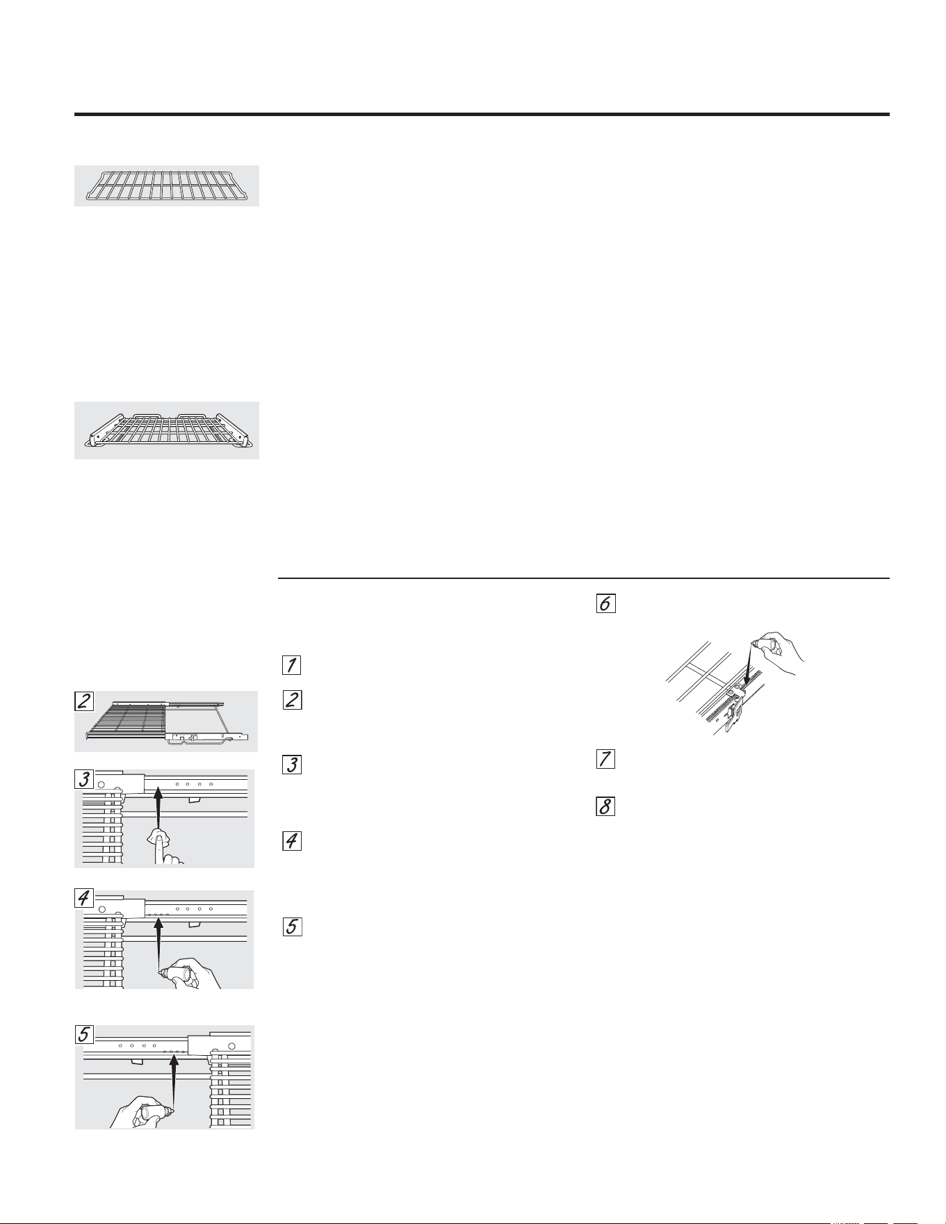
*($SSOLDQFHVFRP
3DUULOODGHH[WHQVLyQ
HQDOJXQRVPRGHORV
3DUDOXEULFDUORVGHVOL]DGRUHV
127$1RURFtHODSDUULOODGHH[WHQVLyQFRQ
SXOYHUL]DGRUSDUDFRFFLyQXRWURVOXEULFDQWHVHQ
VSUD\
4XLWHODSDUULOODGHOKRUQR9HU3DUULOODGH
H[WHQVLyQHQODVHFFLyQ8VRGHOKRUQR
([WLHQGDSRUFRPSOHWRODSDUULOODVREUHXQD
PHVDRPRVWUDGRUGHHQFLPHUD3XHGH
FRORFDUVHSDSHOGHGLDULRGHEDMRGHODSDUULOOD
SDUDXQDOLPSLH]DVHQFLOOD
6LKD\UHVLGXRVHQODVJXtDVGHGHVOL]DPLHQWR
OtPSLHODVFRQXQDWRDOODGHSDSHO
127$7RGRHOOXEULFDQWHGHJUDILWRHOLPLQDGR
GXUDQWHODOLPSLH]DGHEHYROYHUDFRORFDUVH
VHHVWHSVWKURXJK
$JLWHHOOXEULFDQWHGHJUDILWRDQWHVGHDEULUOR
&RPHQ]DQGRFRQHOPHFDQLVPRGH
GHVOL]DPLHQWRL]TXLHUGRGHODSDUULOODFRORTXH
FXDWURJRWDVGHOXEULFDQWHVREUHODVGRV
JXtDVWUDVHUDVFHUFDQDVDORVFRMLQHWHVGH
DSR\R
5HSLWDHQHOPHFDQLVPRGHOODGRGHUHFKRGH
ODJXtD
$EUD\FLHUUHODJXtDYDULDVYHFHVSDUD
GLVWULEXLUHOOXEULFDQWH
9XHOYDDFRORFDUODWDSDGHOOXEULFDQWH\
DJtWHORQXHYDPHQWH'pYXHOWDODSDUULOOD\
UHSLWDORVSDVRV\
&LHUUHODSDUULOODJLUHODSDUULOODGHMDQGRHO
ODGRGHUHFKRKDFLDDUULED\FROyTXHODHQHO
KRUQR9HU3DUULOODGHH[WHQVLyQHQODVHFFLyQ
8VRGHOKRUQR
3DUDOXEULFDUODSDOHWD
$JLWHHOOXEULFDQWH\DSOLTXHHOPLVPRDODVSDUWHV
PyYLOHVGHORVPHFDQLVPRVGHODVSDOHWDVFRPRVH
PXHVWUD
*XtDODGRGHUHFKRDUULED
/DGRGHUHFKR
*XtDODGRGHUHFKRDUULED
/DGRL]TXLHUGR
%DQGHMDVGHOKRUQR
7RGDVODVEDQGHMDVGHOKRUQRSXHGHQOLPSLDUVHD
PDQRFRQXQOLPSLDGRUDEUDVLYRRXQDHVSRQMLOOD
GHDFHUR'HVSXpVGHOLPSLDUHQMXDJXHODV
EDQGHMDVFRQDJXDOLPSLD\VpTXHODVFRQXQSDxR
OLPSLR/DVEDQGHMDVUHYHVWLGDVGHSRUFHODQDJULV
SXHGHQSHUPDQHFHUHQHOKRUQRGXUDQWHHOFLFOR
GHDXWROLPSLH]DVLQVXIULUGDxRV/DVEDQGHMDVGHO
KRUQRGHQtTXHOSXHGHQSHUPDQHFHUHQHOKRUQR
GXUDQWHHOFLFORGHDXWROLPSLH]DSHURSHUGHUiQHO
OXVWUH\UHVXOWDUiGLItFLOGHVOL]DUODV6HUiQHFHVDULR
HQJUDVDUWRGRVORVH[WUHPRVGHODVEDQGHMDVFRQ
XQDFDSDGHDFHLWHYHJHWDOVXDYHGHVSXpVGH
OLPSLDUODVDPDQRRHQHOKRUQR(VWRD\XGDUiD
PDQWHQHUHOIiFLOGHVOL]DPLHQWRGHODVEDQGHMDV
/DVSDUULOODVGHH[WHQVLyQVHSRGUiQOLPSLDUDPDQR
FRQXQOLPSLDGRUDEUDVLYRRHVWURSDMR'XUDQWHOD
OLPSLH]DHYLWHTXHLQJUHVHDJXDROLPSLDGRUHQODV
EDUUDVGHVOL]DQWHVGHH[WHQVLyQDORVFRVWDGRVGHOD
SDUULOOD
127$1RODODYHHQHOODYDYDMLOODV
6LUHWLUDURUHHPSOD]DUODSDUULOODUHVXOWDGLItFLO
OLPSLHOLJHUDPHQWHORVVRSRUWHVGHODSDUULOODFRQ
DFHLWHGHFRFLQD1RSDVHDFHLWHGHFRFFLyQHQORV
GHVOL]DGRUHV
6LUHVXOWDGLItFLOGHVOL]DUODSDUULOODRVLUHVXOWDGLItFLO
DFFLRQDUODSDOHWDGHEHOXEULFDUVHODSDUULOOD
XWLOL]DQGRHOOXEULFDQWHGHJUDILWRHQYLDGRFRQVX
KRUQR3DUDVROLFLWDUOXEULFDQWHGHJUDILWRDGLFLRQDO
OODPHDQXHVWURFHQWURQDFLRQDOGHUHSXHVWRVDO
FRQODUHIHUHQFLD:%7
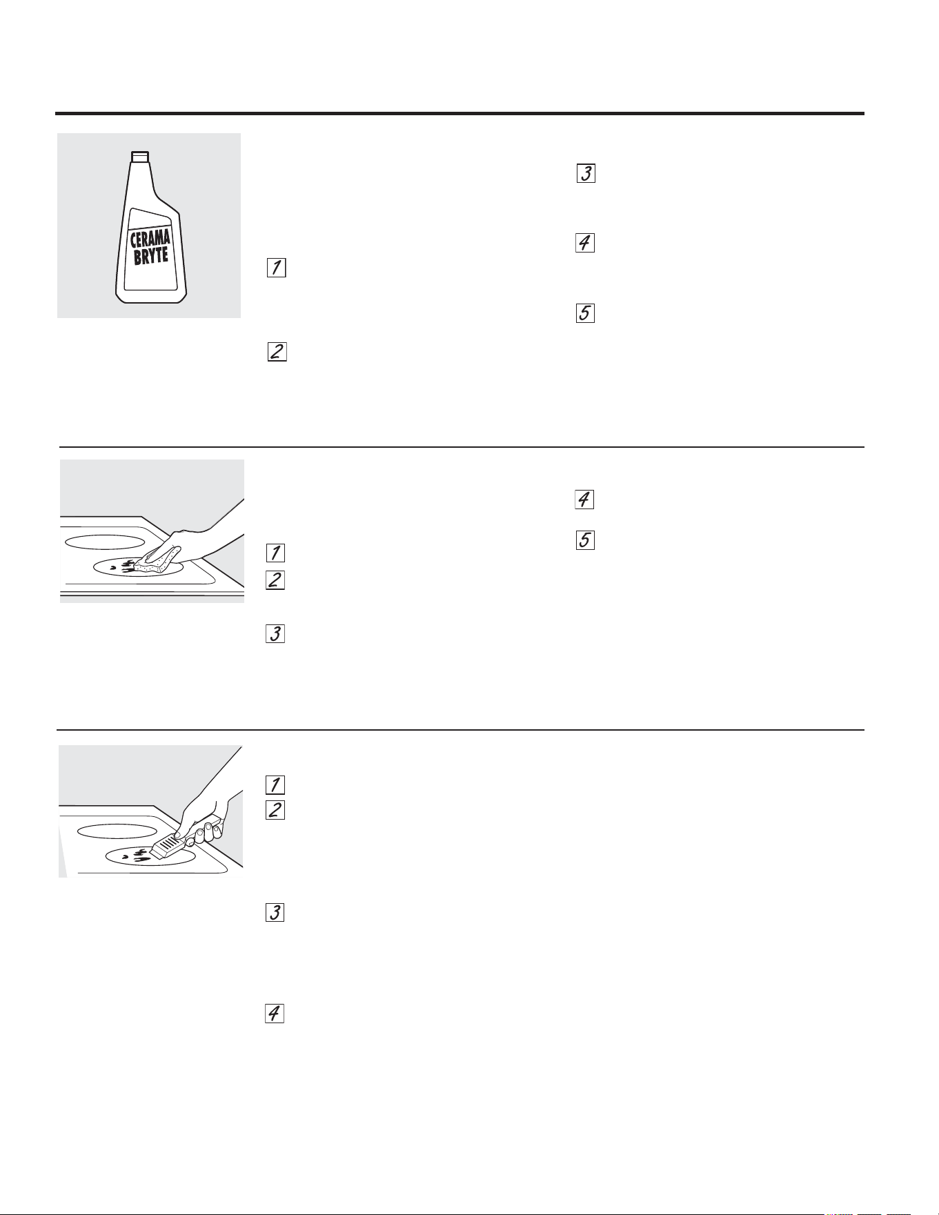
'HMHHQIULDUODHVWXID
8WLOLFHHOUDVSDGRUGHILOR~QLFRDXQ
iQJXORDSUR[LPDGRGHGHJUHHV
FRQWUDODVXSHUILFLHGHOYLGULR\UDVSHOD
VXFLHGDG3XHGHVHUQHFHVDULRDSOLFDU
SUHVLyQDOUDVSDGRUSDUDTXLWDUOD
VXFLHGDG
'HVSXpVGHXWLOL]DUHOUDVSDGRUFRORTXH
XQDVJRWDVGHOLPSLDGRUGHHVWXIDV
FHUiPLFDV&(5$0$%5<7(
VREUHWRGD
HOiUHDGHVXFLHGDGTXHPDGD8WLOLFHHO
SDxRGHOLPSLH]D&(5$0$%5<7(
SDUD
TXLWDUODVXFLHGDGUHVWDQWH
3DUDSURWHFFLyQDGLFLRQDOGHVSXpVGH
KDEHUTXLWDGRWRGRVORVUHVWRVSXOD
WRGDODVXSHUILFLHFRQOLPSLDGRUGH
HVWXIDVFHUiPLFDV&(5$0$%5<7(
\
XQDWRDOODGHSDSHO
5HVLGXRVSHJDGRV
127$8VWHGSXHGH'$³$5ODVXSHUILFLHGH
YLGULRVLXWLOL]DHVSRQMLOODVTXHQRVHDQODV
UHFRPHQGDGDV
'HMHHQIULDUODHVWXID
&RORTXHXQDVJRWDVGHOOLPSLDGRUGH
HVWXIDVFHUiPLFDV&(5$0$%5<7(
VREUHWRGDHOiUHDGHUHVLGXRVSHJDGRV
8WLOL]DQGRHOSDxRGHOLPSLH]D&(5$0$
%5<7(
SDUDHVWXIDVFHUiPLFDVLQFOXLGR
IURWHHOiUHDVXFLDDSOLFDQGRSUHVLyQ
VHJ~QVHDQHFHVDULR
6LTXHGDQUHVWRVUHSLWDORVSDVRV
LQGLFDGRVFRQDQWHULRULGDG
3DUDSURWHFFLyQDGLFLRQDOGHVSXpVGH
KDEHUTXLWDGRWRGRVORVUHVWRVSXOD
WRGDODVXSHUILFLHFRQOLPSLDGRUGH
HVWXIDVFHUiPLFDV&(5$0$%5<7(
\
XQDWRDOOD
GHSDSHO
(OUDVSDGRUGHHVWXIDVFHUiPLFDV
&(5$0$%5<7(
\WRGRVORV
LQVXPRVUHFRPHQGDGRVVH
HQFXHQWUDQGLVSRQLEOHVHQ
QXHVWUR&HQWURGH5HSXHVWRV
9HULQVWUXFFLRQHVEDMRODVHFFLyQ
´3DUDVROLFLWDUUHSXHVWRVµHQOD
SiJLQDVLJXLHQWH
127$1RXWLOLFHKRMDVGHVDILODGDV
RGDxDGDV
5HVLGXRVSHJDGRVUHEHOGHV
8WLOLFHXQSDxRGHOLPSLH]D&(5$0$
%5<7(
SDUDHVWXIDVFHUiPLFDV
/LPSLH]DQRUPDOGHXVRGLDULR
6Ï/2XWLOLFHHOOLPSLDGRUGHHVWXIDVFHUiPLFDV
&(5$0$%5<7(
HQODHVWXIDGHYLGULR2WUDV
FUHPDVSXHGHQQRVHUWDQHIHFWLYDV
3DUDPDQWHQHU\SURWHJHUODVXSHUILFLHGHVX
HVWXIDGHYLGULRVLJDHVWRVSDVRV
$QWHVGHXVDUODHVWXIDSRUSULPHUDYH]
OtPSLHODFRQHOOLPSLDGRUGHHVWXIDV
FHUiPLFDV&(5$0$%5<7(
(VWRD\XGDD
SURWHJHUODHVWXID\KDFHODOLPSLH]DPiV
VHQFLOOD
(OXVRGLDULRGHOOLPSLDGRUGHHVWXIDV
FHUiPLFDV&(5$0$%5<7(
D\XGDUiD
TXHODHVWXIDTXHGHFRPRQXHYD
$JLWHELHQODFUHPDGHOLPSLH]D$SOLTXH
XQDVJRWDVGHOOLPSLDGRUGHHVWXIDV
FHUiPLFDV&(5$0$%5<7(
GLUHFWDPHQWH
VREUHODHVWXID
8WLOLFHXQDWRDOODGHSDSHORXQSDxRGH
OLPSLH]D&(5$0$%5<7(
SDUDHVWXIDV
FHUiPLFDVSDUDOLPSLDUWRGDODVXSHUILFLH
GHODHVWXID
8VHXQSDxRVHFRRXQDWRDOODGHSDSHO
SDUDTXLWDUORVUHVWRVGHOOLPSLDGRU1R
KDFHIDOWDHQMXDJDU
127$(VPX\LPSRUWDQWHTXH12&$/,(17(
ODHVWXIDKDVWDTXHODKD\DOLPSLDGRSRU
FRPSOHWR
/LPSLHODHVWXIDGHVSXpV
GHFDGDGHUUDPH8WLOLFH
HOOLPSLDGRUGHHVWXIDV
FHUiPLFDV&(5$0$%5<7(
&yPROLPSLDUODHVWXIDGHYLGULR
HQDOJXQRVPRGHORV
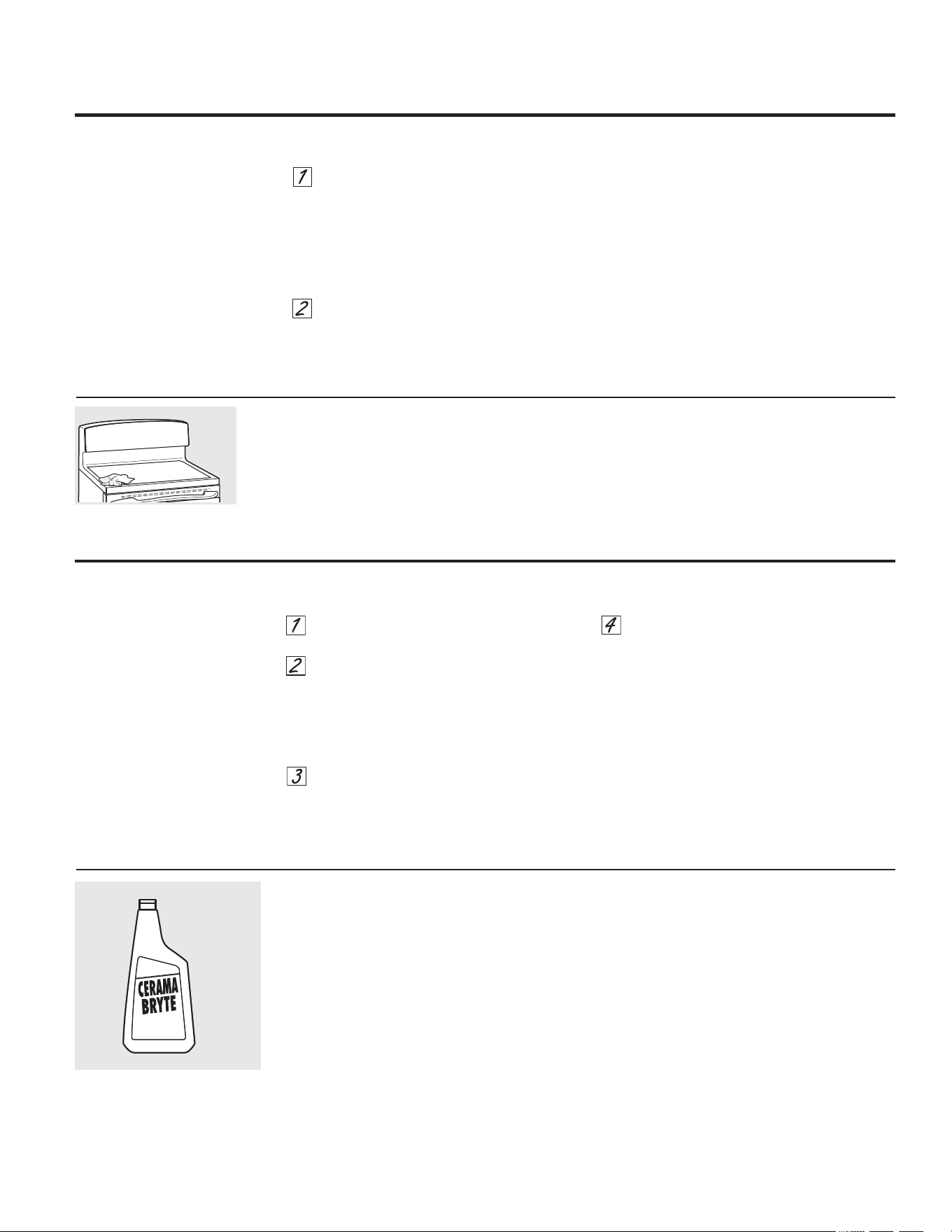
3DUDVROLFLWDUHOOLPSLDGRUGHHVWXIDV
FHUiPLFDV&(5$0$%5<7(
\HOUDVSDGRUGH
HVWXIDVOODPHDQXHVWURQ~PHURJUDWXLWR
&HQWURQDFLRQDOGHSLH]DV
/LPSLDGRUGHHVWXIDVFHUiPLFDV&(5$0$
%5<7(
:;;
5DVSDGRUGHHVWXIDVFHUiPLFDV
&(5$0$%5<7(
:;;
.LW:%;
(ONLWLQFOX\HODFUHPD\HOUDVSDGRUGHHVWXIDV
3DxRVGHOLPSLH]D&(5$0$%5<7(
SDUD
HVWXIDVFHUiPLFDV:;;
$SDJXHWRGDVODVXQLGDGHVGHVXSHUILFLH
4XLWHODVROODVFDOLHQWHV
8WLOL]DQGRXQJXDQWHGHFRFLQD
D8VHXQUDVSDGRUGHILOR~QLFR
UDVSDGRUSDUDHVWXIDVFHUiPLFDV
&(5$0$%5<7(
SDUDGHVSOD]DUHO
GHUUDPHDXQiUHDIUtDGHODHVWXID
E4XLWHHOGHUUDPHFRQWRDOODVGHSDSHO
&XDOTXLHUGHUUDPHUHVWDQWHGHEHGHMDUVH
KDVWDTXHODVXSHUILFLHGHODHVWXIDVHKD\D
HQIULDGR
1RXVHODVXQLGDGHVGHVXSHUILFLHGH
QXHYRKDVWDTXHWRGRVORVUHVWRVVH
KD\DQHOLPLQDGRSRUFRPSOHWR
127$6LODVXSHUILFLHGHYLGULR\DKDVXIULGR
PDUFDVRKHQGLGXUDVHOYLGULRGHODHVWXID
GHEHUiFDPELDUVH(QHVHFDVRVHUiQHFHVDULDOD
DWHQFLyQGHXQWpFQLFR
'DxRVSRUGHUUDPHVD]XFDUDGRV\SOiVWLFRGHUUHWLGR
/RVGHUUDPHVD]XFDUDGRV
FRPRJHODWLQDVGXOFH
FDUDPHORMDUDEHVRSOiVWLFRV
GHUUHWLGRVSXHGHQPDUFDU
ODVXSHUILFLHGHODHVWXIDQR
FXELHUWRSRUODJDUDQWtDD
PHQRVTXHHOGHUUDPHVH
TXLWHPLHQWUDVHVWiFDOLHQWH
'HEHWHQHUVHPXFKRFXLGDGR
DOUHPRYHUVXVWDQFLDV
FDOLHQWHV
$VHJ~UHVHGHXWLOL]DUXQ
UDVSDGRUQXHYR\DILODGR
1RXWLOLFHKRMDVGHVDILODGDVR
GDxDGDV
7HQJDFXLGDGRGHQRGHVOL]DUROODV\
VDUWHQHVDWUDYpVGHVXHVWXID'HMDUi
PDUFDVGHPHWDOVREUHODVXSHUILFLHGHOD
HVWXID
(VWDVPDUFDVSXHGHQTXLWDUVHXWLOL]DQGR
OLPSLDGRUGHHVWXIDVFHUiPLFDV&(5$0$
%5<7(
FRQHOSDxRGHOLPSLH]D&(5$0$
%5<7(
SDUDHVWXIDVFHUiPLFDV
6LVHSHUPLWHTXHROODVFRQXQDFDSDILQD
GHDOXPLQLRRFREUHKLHUYDQHQVHFROD
FDSDSXHGHGHMDUXQDGHFRORUDFLyQ
QHJUDHQODHVWXID
(VWRGHEHTXLWDUVHGHLQPHGLDWRDQWHV
GHFDOHQWDUGHQXHYRRODGHFRORUDFLyQ
SXHGHOOHJDUDVHUSHUPDQHQWH
127$9HULILTXHFRQGHWHQLPLHQWRTXHODEDVH
GHODVROODVQRVHDiVSHUDSDUDQRUD\DUOD
HVWXID
0DUFDVGHPHWDO\UD\RQHV
3DUDVROLFLWDUUHSXHVWRV
6XSHUILFLHGHYLGULRSRVLELOLGDGHVGHGDxRSHUPDQHQWH
3DUDOLPSLDUHOVHOODGRGHODHVWXIDDOUHGHGRU
GHORVERUGHVGHYLGULRFRORTXHXQSDxR
K~PHGRVREUHORVPLVPRVGXUDQWHXQRV
PLQXWRV\OXHJROLPSLHFRQOLPSLDGRUHVQR
DEUDVLYRV
6HOODGRGHODHVWXID
*($SSOLDQFHVFRP
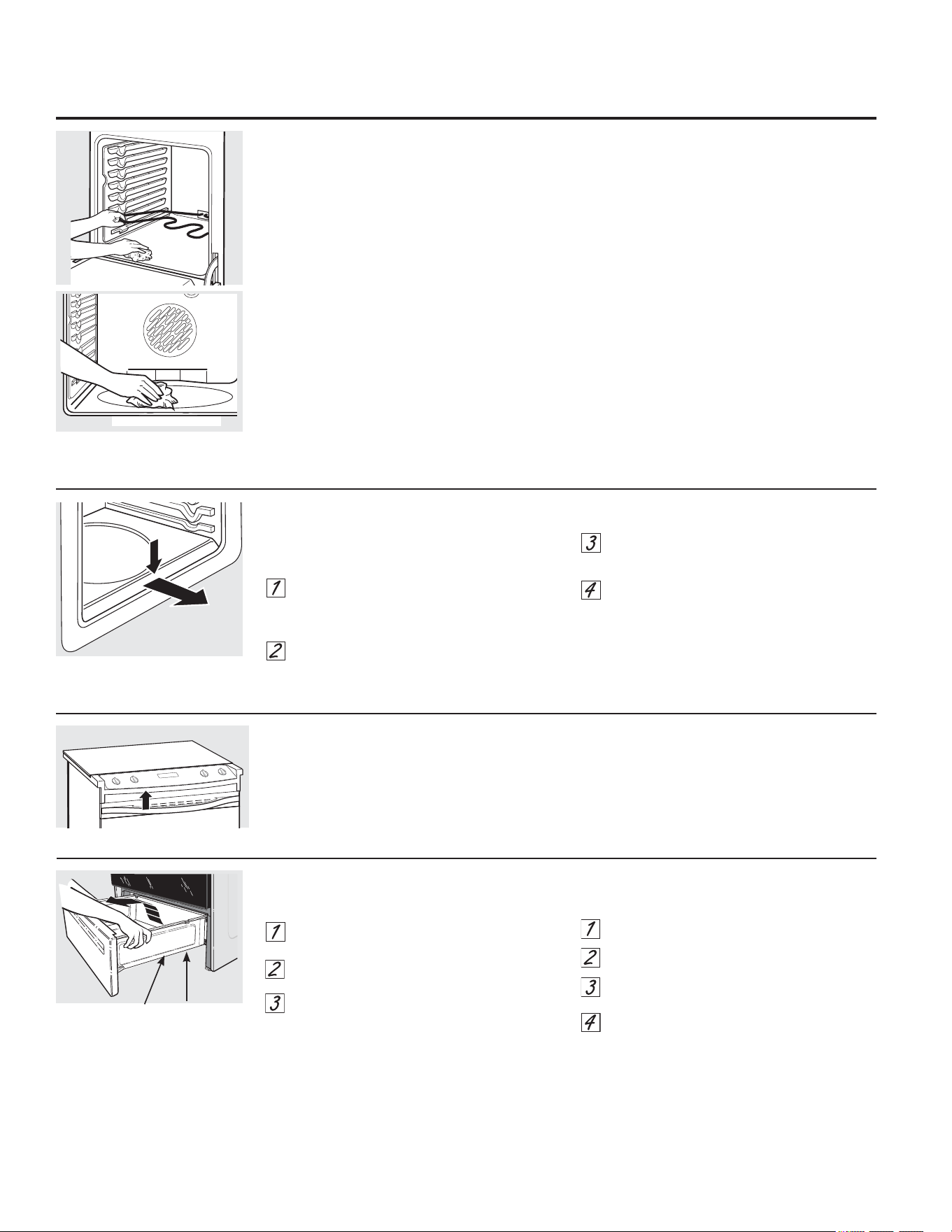
5HPRFLyQGHOFDMyQGHDOPDFHQDPLHQWR
3DUDTXLWDUHOFDMyQ
7LUHGHOFDMyQKDFLDIXHUDKDVWDTXHVH
GHWHQJD
/HYDQWHHOIUHQWHGHOFDMyQKDVWDTXHODV
WUDEDVVDOJDQGHODVJXtDV
5HWLUHHOFDMyQ
3DUDYROYHUDFRORFDUHOFDMyQ
&RORTXHORVULHOHVGHOFDMyQHQODVJXtDV
(PSXMHHOFDMyQKDVWDTXHVHGHWHQJD
/HYDQWHHOIUHQWHGHOFDMyQ\HPSXMHKDVWD
TXHODVWUDEDVVXSHUHQODVJXtDV
%DMHHOIUHQWHGHOFDMyQ\HPSXMHKDFLDDEDMR
KDVWDTXHFLHUUH
*XtDGHWRSH
5LHO
&XLGDGR\OLPSLH]DGHODFRFLQD
(OHPHQWRVFDOHQWDGRUHVGHOKRUQR
1ROLPSLHHOHOHPHQWRSDUDKRUQHDURHO
HOHPHQWRSDUDDVDU/DVVXFLHGDGHVVH
TXHPDUiQFXDQGRVHFDOLHQWHQORVHOHPHQWRV
3DUDOLPSLDUHOSLVRGHOKRUQRHOHYH
VXDYHPHQWHHOHOHPHQWRDKRUQHDU(QDOJXQRV
PRGHORVHOHOHPHQWRDKRUQHDUQRHVWi
H[SXHVWR\VHHQFXHQWUDGHEDMRGHOSLVRGHO
VXHOR/LPSLHFRQDJXDFDOLHQWH\MDEyQ
/LPSLHFRQXQSDxRORVGHVHFKRV
UHEHOGHVDFXPXODGRVHQHOSLVRGHO
KRUQR
9HQWLODFLyQGHOKRUQR
HQDOJXQRVPRGHORV
/DYHQWLODFLyQGHOKRUQRVHHQFXHQWUDHQFLPD
GHOODGRL]TXLHUGRGHODSXHUWD
(VWDiUHDSXHGHFDOHQWDUVHGXUDQWHHOXVRGHO
KRUQR
5HVXOWDQRUPDOTXHVDOJDYDSRUGHODYHQWLODFLyQ
/DYHQWLODFLyQHVLPSRUWDQWHSDUDORJUDUXQD
DGHFXDGDFLUFXODFLyQGHDLUH1XQFDEORTXHHHVWD
YHQWLODFLyQ
3LVRGHOKRUQRGHVPRQWDEOHHQDOJXQRVPRGHORV
&yPRTXLWDUHOSLVRGHOKRUQRSDUDXQD
OLPSLH]DPiVIiFLO
4XLWHODSXHUWDGHOKRUQRXWLOL]DQGRODV
LQVWUXFFLRQHVGHODVHFFLyQ3XHUWDGHO
KRUQRGHVPRQWDEOH
3UHVLRQHKDFLDDEDMR\TXLWHHOSLVR
GHVPRQWDEOHGHOKRUQR
/LPSLHHOSLVRGHOKRUQRFRQDJXDWLELD
MDERQRVD
&XDQGRYXHOYDDFRORFDUHOSLVRGHOKRUQR
DVHJ~UHVHGHGHVOL]DUORELHQKDVWDOD
SDUWHWUDVHUDGHOKRUQR
,03257$17(6LHPSUHYXHOYDDFRORFDUHOSLVR
GHVPRQWDEOHDQWHVGHOSUy[LPRXVR
3UHVLRQHKDFLDDEDMR\TXLWH

&RQVHMRVSDUDLGHQWLILFDFLyQ\VROXFLyQGHSUREOHPDV
£$KRUUHWLHPSR\GLQHUR/HDODVWDEODVGHODVVLJXLHQWHV
SiJLQDV\TXL]iVQRQHFHVLWHOODPDUDOVHUYLFLRWpFQLFR
3UREOHPD &DXVDVSRVLEOHV 4XpKDFHU
/DVXQLGDGHVGH 6HHVWiQXWLOL]DQGRUHFLSLHQWHV 8VHUHFLSLHQWHVGHEDVHSODQD\TXHVHDMXVWHQ
VXSHUILFLHQRPDQWLHQHQ
GHFRFFLyQLQDGHFXDGRV DOGLiPHWURGHODXQLGDGGHVXSHUILFLHHOHJLGD
XQKHUYRUFRQVWDQWHR
(QDOJXQDVUHJLRQHVODHQHUJtD &XEUDHOUHFLSLHQWHFRQXQDWDSDKDVWDREWHQHUHOFDORU
ODFRFFLyQHVOHQWD
YROWDMHSXHGHVHUEDMD GHVHDGR
/RVHOHPHQWRVGH (OIXVLEOHSXHGHKDEHUVH &DPELHHOIXVLEOHRYXHOYDDFRQILJXUDUHOLQWHUUXSWRU
VXSHUILFLHQRIXQFLRQDQ TXHPDGRRHOLQWHUUXSWRUGH GHFLUFXLWRV
ELHQ FLUFXLWRVSXHGHKDEHUVDOWDGR
/RVFRQWUROHVGHODHVWXID 9HULILTXHTXHVHKD\DFRQILJXUDGRHOFRQWUROFRUUHFWR
HVWiQPDOFRQILJXUDGRV SDUDHOHOHPHQWRGHVXSHUILFLHTXHHVWiXWLOL]DQGR
/DXQLGDGGHVXSHUILFLH (VWRHVQRUPDO/DXQLGDGVLJXH
GHMDGHUHVSODQGHFHU HQFHQGLGD\FDOLHQWH
FXDQGRVHFDPELDD
XQDFRQILJXUDFLyQPHQRU
5D\RQHVSXHGHQSDUHFHU
6HHVWiQXVDQGRPpWRGRV
/RVUD\RQHVQRSXHGHQUHPRYHUVH/RVUD\RQHVPiVSHTXHxRV
FRPRURWXUDVHQOD GHOLPSLH]DLQFRUUHFWRV
VHYROYHUiQPHQRVYLVLEOHVFRPRUHVXOWDGRGHODOLPSLH]D
VXSHUILFLHGHYLGULR
6HHVWiQXVDQGRUHFLSLHQWHV 3DUDHYLWDUUD\RQHVXVHORVSURFHGLPLHQWRVGHOLPSLH]D
GHODHVWXID
FRQEDVHViVSHUDVRKD\ UHFRPHQGDGRV9HULILTXHTXHODVEDVHVGHORVUHFLSLHQWHV
SDUWtFXODVJUXHVDVVDORDUHQD HVWpQOLPSLDVDQWHVGHOXVR\XWLOLFHUHFLSLHQWHVFRQEDVHV
HQWUHHOUHFLSLHQWH\ODVXSHUILFLH OLVDV
GHODHVWXID
6HKDGHVOL]DGRXQUHFLSLHQWHD
WUDYpVGHODVXSHUILFLHGHODHVWXID
ÈUHDVGHGHFRORUDFLyQ 1RVHOLPSLDURQORVGHUUDPHV
9HUODVHFFLyQ&yPROLPSLDUODHVWXIDGHYLGULR
HQODHVWXID
GHDOLPHQWRVDQWHVGHOXVR
VLJXLHQWH
6XSHUILFLHFDOLHQWHHQ (VWRHVQRUPDO/DVXSHUILFLHSXHGHSDUHFHUGHFRORUDGD
XQPRGHORFRQXQDHVWXID FXDQGRHVWiFDOLHQWH(VWRHVWHPSRUDO\GHVDSDUHFHUi
GHFRORUFODUR DPHGLGDTXHVHHQIUtDHOYLGULR
3OiVWLFRGHUUHWLGR /DHVWXIDFDOLHQWHHQWUy 9HUODVHFFLyQ6XSHUILFLHGHYLGULRSRVLELOLGDGHVGHGDxR
VREUHODVXSHUILFLH HQFRQWDFWRFRQSOiVWLFRSHUPDQHQWHHQODVHFFLyQ&yPROLPSLDUODHVWXID
FRORFDGRVREUHODPLVPD GHYLGULR
0DUFDVRKHQGLGXUDV 6HKDGHUUDPDGRXQDPH]FOD /ODPHDXQWpFQLFRFDOLILFDGRSDUDHOUHHPSOD]R
HQODHVWXID D]XFDUDGDFDOLHQWHHQODHVWXID
/DVXQLGDGHVGHVXSHUILFLH
6HHVWiQXWLOL]DQGRUHFLSLHQWHV 8VHVyORUHFLSLHQWHVGHEDVHSODQDSDUDPLQLPL]DU
VHHQFLHQGHQ\DSDJDQ
GHFRFFLyQLQDGHFXDGRV HOHQFHQGLGR\DSDJDGR
FRQPXFKDIUHFXHQFLD
/DOX]GHOKRUQR /DERPELOODGHOX]HVWiIORMD $MXVWHRFDPELHODERPELOOD
QRIXQFLRQD
(OKRUQRQRIXQFLRQD (OHQFKXIHGHODFRFLQD 9HULILTXHTXHHOHQFKXIHHOpFWULFRHVWpFRQHFWDGR
QRHVWiLQWURGXFLGRGHOWRGR DXQWRPDFRUULHQWHFRQWHQVLyQ\DGHFXDGDFRQH[LyQ
HQHOWRPDFRUULHQWH DWLHUUD
(OIXVLEOHSXHGHKDEHUVH &DPELHHOIXVLEOHRYXHOYDDFRQILJXUDUHOLQWHUUXSWRU
TXHPDGRRHOLQWHUUXSWRUGH GHFLUFXLWRV
FLUFXLWRVSXHGHKDEHUVDOWDGR
/RVFRQWUROHVGHOKRUQRHVWiQ 9HUODVHFFLyQ&yPRXVDUHOKRUQR
PDOFRQILJXUDGRV
(OKRUQRHVWiPX\FDOLHQWH 'HMHTXHHOKRUQRVHHQIUtHSRUGHEDMR
GHODWHPSHUDWXUDGHEORTXHR
$QWHVGHOODPDUDOVHUYLFLRWpFQLFR« *($SSOLDQFHVFRP

&RQVHMRVSDUDLGHQWLILFDFLyQ\VROXFLyQGHSUREOHPDV
$QWHVGHOODPDUDOVHUYLFLRWpFQLFR«
3UREOHPD &DXVDVSRVLEOHV 4XpKDFHU
/RVDOLPHQWRVQR /RVFRQWUROHVGHOKRUQRHVWiQ 9HUODVHFFLyQ&yPRXVDUHOKRUQR
VHKRUQHDQRURVWL]DQ PDOFRQILJXUDGRV
FRUUHFWDPHQWH
/DSRVLFLyQGHODEDQGHMDHV 9HUODVHFFLyQ&yPRXVDUHOKRUQR
LQFRUUHFWDRQRHVWiQLYHODGD
6HHVWiQXWLOL]DQGRUHFLSLHQWHV 9HUODVHFFLyQ&yPRXVDUHOKRUQR
GHFRFFLyQLQFRUUHFWRVR
GHWDPDxRLQDSURSLDGR
(OWHUPRVWDWRGHOKRUQRGHEH9HUODVHFFLyQ$MXVWHHOWHUPRVWDWRGHOKRUQRXVWHG
DMXVWDUVHPLVPR
/RVDOLPHQWRVQR /RVFRQWUROHVGHOKRUQRHVWiQ $VHJ~UHVHGHSUHVLRQDUHOERWyQ%52,/+,/2
VHDVDQGHPDQHUD PDOFRQILJXUDGRV DVDUDOWDEDMD
DGHFXDGD
6HHVWiXVDQGRXQDSRVLFLyQ 9HUOD*XtDGHDVDGR
GHEDQGHMDLQDGHFXDGD
/RVUHFLSLHQWHVQRVRQ 3DUDPHMRUHVUHVXOWDGRVXWLOLFHXQUHFLSLHQWHGLVHxDGR
DGHFXDGRVSDUDDVDU SDUDDVDGR
/DVRQGDHVWiHQFKXIDGD 'HVHQFKXIH\TXLWHODVRQGDGHOKRUQR
GHQWURGHODVDOLGDGHOKRUQR
HQDOJXQRVPRGHORV
(QDOJXQDVUHJLRQHVODHQHUJtD 3UHFDOLHQWHHOHOHPHQWRSDUDDVDUGXUDQWHPLQXWRV
YROWDMHSXHGHVHUEDMD
$VHSRUHOSHUtRGRGHWLHPSRPiVSURORQJDGRTXH
VHUHFRPLHQGHHQOD*XtDGHDVDGR
/DWHPSHUDWXUD (OWHUPRVWDWRGHOKRUQRGHEH 9HUODVHFFLyQ$MXVWHHOWHUPRVWDWRGHOKRUQRXVWHG
GHOKRUQRHVPX\DOWD DMXVWDUVHPLVPR
RPX\EDMD
(OFDMyQGH (OVRSRUWHGHFDMyQWUDVHUR 9XHOYDDFRORFDUHOFDMyQ9HUODVLQVWUXFFLRQHVGH
DOPDFHQDPLHQWR VHHQFXHQWUDVREUHHOULHO5HPRFLyQGHOFDMyQGHDOPDFHQDPLHQWRHQODVHFFLyQ
HVWiWRUFLGRGHODJXtD&XLGDGR\OLPSLH]DGHODFRFLQD
9HULILTXHTXHHOFDMyQHVWpELHQFRORFDGRVLVHORTXLWD
(OFDMyQGH (OFDEOHGHHQHUJtDSXHGH &DPELHODXELFDFLyQGHOFDMyQ\GHOFDEOHGHHQHUJtD
DOPDFHQDPLHQWR HVWDUREVWUX\HQGRHOFDMyQ 9HUODVLQVWUXFFLRQHVGH5HPRFLyQGHOFDMyQGH
QRFLHUUD HQODSDUWHWUDVHUDLQIHULRU DOPDFHQDPLHQWRHQODVHFFLyQ&XLGDGR\OLPSLH]D
GHODFRFLQD GHODFRFLQD
(OVRSRUWHGHFDMyQWUDVHUR 9XHOYDDFRORFDUHOFDMyQ9HUODVLQVWUXFFLRQHVGH
VHHQFXHQWUDVREUHHOULHO5HPRFLyQGHOFDMyQGHDOPDFHQDPLHQWRHQODVHFFLyQ
GHODJXtD&XLGDGR\OLPSLH]DGHODFRFLQD
/DSXHUWDGHOKRUQR /DSXHUWDQRHVWiELHQ 'DGRTXHODSXHUWDGHOKRUQRHVGHVPRQWDEOHDYHFHVHVWiWRUFLGD
DOLQHDGD VHGHVHTXLOLEUDGXUDQWHODLQVWDODFLyQ
3DUDHQGHUH]DUODSXHUWDSUHVLRQHKDFLDDEDMRVREUHODHVTXLQD
VXSHULRU

3UREOHPD &DXVDVSRVLEOHV 4XpKDFHU
(OUHORM\HOWHPSRUL]DGRU
(OHQFKXIHGHODFRFLQDQRHVWi
9HULILTXHTXHHOHQFKXIHHOpFWULFRHVWpFRQHFWDGRDXQ
QRIXQFLRQDQ
LQWURGXFLGRGHOWRGRHQHOWRPDFRUULHQWH
WRPDFRUULHQWHFRQWHQVLyQ\DGHFXDGDFRQH[LyQDWLHUUD
(OIXVLEOHSXHGHKDEHUVH &DPELHHOIXVLEOHRYXHOYDDFRQILJXUDUHOLQWHUUXSWRU
TXHPDGRRHOLQWHUUXSWRU GHFLUFXLWRV
GHFLUFXLWRVSXHGHKDEHUVDOWDGR
/RVFRQWUROHVGHOKRUQRHVWiQ 9HUODVHFFLyQ&yPRXVDUHOWHPSRUL]DGRUGHFRFLQD
PDOFRQILJXUDGRV
(OKRUQRQRUHDOL]D /DWHPSHUDWXUDGHOKRUQRHVWi 'HMHTXHODFRFLQDVHHQIUtH\YXHOYDDFRQILJXUDU
ODDXWROLPSLH]D PX\HOHYDGDSDUDFRQILJXUDU ORVFRQWUROHV
ODIXQFLyQGHDXWROLPSLH]D
/RVFRQWUROHVGHOKRUQRHVWiQ 9HUODVHFFLyQ8VRGHOKRUQRFRQDXWROLPSLH]D
PDOFRQILJXUDGRV
/DVRQGDHVWiHQFKXIDGD 4XLWHODVRQGDGHOKRUQR
GHQWURGHODERFDGHVDOLGD
GHOKRUQRHQDOJXQRVPRGHORV
5XLGRGH´FUXMLGRVµ (VHOVRQLGRGHOPHWDO (VWRHVQRUPDO
R´FKDVTXLGRVµ FDOHQWiQGRVH\HQIULiQGRVH
GXUDQWHODVIXQFLRQHV
GHFRFFLyQ\OLPSLH]D
+XPRH[FHVLYR 6XFLHGDGH[FHVLYD 3UHVLRQHHOERWyQ&/($52))ERUUDUDSDJDGR
HQHOKRUQRGXUDQWH $EUDODVYHQWDQDVSDUDTXHVDOJDHOKXPR(VSHUHHO
FLFORGHOLPSLH]D KDVWDTXHVHDSDJXH/2&.(''HVSXpVGHTXH
VHHQIUtHHOKRUQROLPSLHHOH[FHVRGHVXFLHGDG\YXHOYDD
FRQILJXUDUHOFLFORGHOLPSLH]D
/DSXHUWDGHOKRUQR (OKRUQRHVWiPX\FDOLHQWH 'HMHTXHHOKRUQRVHHQIUtHSRUGHEDMR
QRVHDEUHGHVSXpVGHO GHODWHPSHUDWXUDGHEORTXHR
XQFLFORGHOLPSLH]D
(OKRUQRQRHVWiOLPSLR /RVFRQWUROHVGHOKRUQRQRHVWiQ 9HUODVHFFLyQ8VRGHOKRUQRFRQDXWROLPSLH]D
GHVSXpVGHXQFLFOR FRQILJXUDGRVFRUUHFWDPHQWH
GHOLPSLH]D
(OKRUQRHVWDEDPX\VXFLR /LPSLHORVGHUUDPHVPiVUHEHOGHVDQWHVGHLQLFLDUHOFLFOR
GHOLPSLH]D/RVKRUQRVPX\VXFLRVSXHGHQQHFHVLWDUXQD
QXHYDDXWROLPSLH]DRXQDOLPSLH]DPiVSURORQJDGD
/DOX]GHEORTXHR 6HKDVHOHFFLRQDGRHOFLFOR &LHUUHODSXHUWDGHOKRUQR
´/2&.('µGHVWHOOD GHDXWROLPSLH]DSHUR
HQODSDQWDOOD ODSXHUWDQRHVWiFHUUDGD
GHOKRUQR
/DOX]GHEORTXHR /DSXHUWDGHOKRUQR 3UHVLRQHHOERWyQ&/($52))ERUUDUDSDJDGR
´/2&.('µHVWi HVWiEORTXHDGDSRUTXH 'HMHHQIULDUHOKRUQR
HQFHQGLGDFXDQGR ODWHPSHUDWXUDGHQWUR
GHVHDFRFLQDU GHOPLVPRQRKDGHVFHQGLGR
GHEDMRGHODWHPSHUDWXUD
GHEORTXHR
´)³µ\XQQ~PHUR +D\XQFyGLJRGHHUURU 'HVHQFKXIHHOKRUQRSRUORPHQRVVHJXQGRV\OXHJR
ROHWUDGHVWHOODQ GHIXQFLyQ YXHOYDDHQFKXIDUOR6LHOFyGLJRGHHUURUGHIXQFLyQ
HQODSDQWDOOD VHUHSLWHOODPHDOVHUYLFLRWpFQLFR
$QWHVGHOODPDUDOVHUYLFLRWpFQLFR«
*($SSOLDQFHVFRP

&RQVHMRVSDUDLGHQWLILFDFLyQ\VROXFLyQGHSUREOHPDV
3UREOHPD &DXVDVSRVLEOHV 4XpKDFHU
(OFRQWUROHPLWHXQD 2OYLGyLQJUHVDU 3UHVLRQHHOERWyQ%$.(KRUQHDU\ODWHPSHUDWXUD
VHxDOGHVSXpVGHLQJUHVDU
XQWHPSHUDWXUDGHKRUQHDGR GHVHDGDRHOERWyQ6(/)&/($1DXWROLPSLH]D
XQWLHPSRGHFRFFLyQ RXQKRUDULRGHOLPSLH]D \HOWLHPSRGHOLPSLH]DGHVHDGR
RGHLQLFLR
/DSDQWDOODTXHGD
(OIXVLEOHSXHGHKDEHUVHTXHPDGR
&DPELHHOIXVLEOHRYXHOYDDFRQILJXUDUHOLQWHUUXSWRU
HQEODQFR RHOLQWHUUXSWRUGHFLUFXLWRV GHFLUFXLWRV
SXHGHKDEHUVDOWDGR
(OUHORMVHHQFXHQWUDHQ 9HUODVHFFLyQGH&DUDFWHUtVWLFDVHVSHFLDOHVGH
HOPRGRVLQYLVXDOL]DFLyQ ORVFRQWUROHVGHOKRUQR
/DSDQWDOODGHVWHOOD &RUWHGHHQHUJtD 5HFRQILJXUHHOUHORM
/DSDQWDOODQR
/RVERWRQHVGHFRQWUROGHOKRUQR
/RVERWRQHV%52,/+,/2DVDUDOWREDMR\%$.(
PXHVWUD´6)µ
QRVHSUHVLRQDURQFRUUHFWDPHQWH
KRUQHDUGHEHQSUHVLRQDUVHDOPLVPRWLHPSR
\VRVWHQHUVHGXUDQWHVHJXQGRV
$SDUHFH´3UREHµ (VWROHUHFXHUGDGHLQJUHVDU ,QJUHVHXQDWHPSHUDWXUDGHVRQGD
VRQGDHQODSDQWDOOD XQDWHPSHUDWXUDGHVRQGD
DOJXQRVPRGHORV GHVSXpVGHHQFKXIDUOD
&RUWHGHHQHUJtD &RUWHGHHQHUJtDRVXELGD 5HFRQILJXUHHOUHORM6LHOKRUQRHVWDEDHQXVRXVWHG
HOUHORMGHVWHOOD GHWHQVLyQ GHEHUHFRQILJXUDUORSUHVLRQDQGRHOERWyQ&/($52))
ERUUDUDSDJDGRFRQILJXUDQGRHOUHORM\
UHFRQILJXUDQGRFXDOTXLHUIXQFLyQGHFRFFLyQ
(PLVLyQGHYDSRU
&XDQGRVHXWLOL]DQ
ORVKRUQRV
(VWRHVQRUPDO
GHVGHODYHQWLODFLyQ
HVQRUPDOYHUXQDHPLVLyQGHYDSRU
GHODYHQWLODFLyQGHOKRUQR$PHGLGD
TXHHOQ~PHURGHEDQGHMDVR
ODFDQWLGDGGHDOLPHQWRVDFRFLQDU
VHLQFUHPHQWDODFDQWLGDGGHYDSRU
YLVLEOHVHHOHYDUi
8QRORUD´TXHPDGRµ (VWRHVQRUPDOHQXQKRUQR 3DUDDFHOHUDUHOSURFHVRFRQILJXUHXQFLFORGH
R´DFHLWRVRµVDOH QXHYR\GHVDSDUHFHFRQ DXWROLPSLH]DGXUDQWHXQPtQLPRGHKRUDV9HU
GHODYHQWLODFLyQ HOWLHPSR 9HUODVHFFLyQ8VRGHOKRUQRFRQDXWROLPSLH]D
2ORUSHQHWUDQWH /DVSULPHUDVYHFHVTXH (VWRHVWHPSRUDO
VHXWLOL]DHOKRUQRHVQRUPDO
VHQWLUXQRORUSURYHQLHQWH
GHODLVODQWHTXHUHFXEUH
ODSDUWHLQWHUQDGHOKRUQR
6HR\HXQYHQWLODGRU 8QYHQWLODGRUGHFRQYHFFLyQ(VWRHVQRUPDO3DUDSRWHQFLDUDOPi[LPRXQDFRFFLyQ
HQDOJXQRVPRGHORV
SXHGHHQFHQGHUVH\DSDJDUVH SDUHMDHOYHQWLODGRUHVWiGLVHxDGRSDUDJLUDUHQDPEDV
DXWRPiWLFDPHQWH GLUHFFLRQHVFRQXQDSDXVDHQWUHHOODV
(OYHQWLODGRUGHFRQYHFFLyQIXQFLRQDGXUDQWHHO
SUHFDOHQWDPLHQWRGHOFLFORGHKRUQHDGR(OYHQWLODGRU
VHDSDJDUiGHVSXpVGHTXHHOKRUQRKD\DDOFDQ]DGR
ODWHPSHUDWXUDFRQILJXUDGD(VWRHVQRUPDO
8QYHQWLODGRUGHUHIULJHUDFLyQ(VWRHVQRUPDO6HHQFHQGHUi\DSDJDUiXQYHQWLODGRU
SXHGHHQFHQGHUVH\DSDJDUVH GHUHIULJHUDFLyQSDUDHQIULDUODVSLH]DVLQWHUQDV3XHGH
DXWRPiWLFDPHQWH IXQFLRQDUD~QGHVSXpVGHTXHHOKRUQRVHKD\DDSDJDGR
5HVXOWDGLItFLOGHVOL]DU /DVSDUULOODVGHFRORU $SOLTXHXQDSHTXHxDFDQWLGDGGHDFHLWHYHJHWDOHQ
ODVEDQGHMDVGHOKRUQR SODWHDGREULOODQWHVHOLPSLDURQ XQDWRDOODGHSDSHO\IURWHORVERUGHVGHODVEDQGHMDV
HQXQFLFORGHDXWROLPSLH]D GHOKRUQR1RURFtHFRQ3DP
XRWUROXEULFDQWHHQVSUD\
(OFDMyQQRVHGHVOL]D (OFDMyQQRHVWiELHQ ([WLHQGDHOFDMyQSRUFRPSOHWR\SUHVLyQHORKDVWD
ELHQRKD\TXHWLUDU DOLQHDGR HOIRQGR9HUODVHFFLyQ&XLGDGR\OLPSLH]DGHODFRFLQD
GHpO
(OFDMyQHVWiPX\FDUJDGR 5HGX]FDHOSHVR5HGLVWULEX\DHOFRQWHQLGRGHOFDMyQ
RODFDUJDQRHVWiHTXLOLEUDGD
$QWHVGHOODPDUDOVHUYLFLRWpFQLFR«
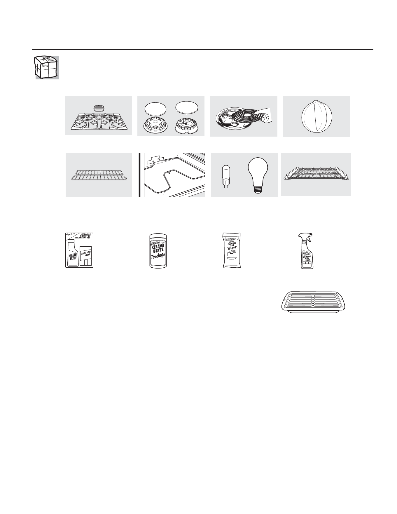
$FFHVRULRV *($SSOLDQFHVFRP
¢'HVHDDOJRPiV"1RWRGRVORVDFFHVRULRVVHHQFXHQWUDQGLVSRQLEOHVSDUDWRGRV
ORVPRGHORV
8VWHGSXHGHHQFRQWUDUHVWRVDFFHVRULRV\PXFKRVPiVHQ*($SSOLDQFHVFRPROODPHDO
HQKRUDULRGHWUDEDMRQRUPDO7HQJDOLVWRHOQ~PHURGHPRGHOR
£3UXHEHHVWRVRWURVH[FHOHQWHVSURGXFWRVSDUDTXHVXFRFLQDVHYHDHVWXSHQGD
£$SURYHFKHDOPi[LPRVXEDQGHMDSDUDDVDU1RSDUDXVDUFRQPRGHORVGHFDMyQDVDGRU
£8WLOLFHVXEDQGHMD\WDSDGHUHMLOODSDUDDVDUKDPEXUJXHVDVIUXWRVGHPDUILOHWHVYHJHWDOHVSDQFHWD
FRVWLOODV\PXFKRPiV/DEDQGHMDLQIHULRUUHWLHQHHOH[FHVRGHJUDVDV\DFHLWHV
3LH]D*(JHQXLQD
)iFLOGHOLPSLDU
*DUDQWtDGHXQDxR
£2IHUWDGHWLHPSROLPLWDGR£(QYtRVLQFDUJR
&XDQGRVROLFLWHODEDQGHMDSDUDDVDUGHQWURGHORVGtDVGHKDEHUDGTXLULGRVXSURGXFWRGHFRFLQD*(
3HTXHxD *UDQGH ([WUDJUDQGH
1GHSLH]D :%; :%; :%;
'LPHQVLRQHV µ$[µ$[µ3 µ$[µ$[µ3 µ$[µ$[µ3
/DEDQGHMDSDUDDVDUJUDQGHHVWiQGDUQRHQWUDHQFRFLQDVGHSXOJDGDV
/DEDQGHMDH[WUDJUDQGHQRHQWUDHQKRUQRVGHSDUHGHVGHSXOJDGDVHPSRWUDGDVGHSXOJDGDVRFRFLQDVGHSXOJDGDV
/ODPHDORXWLOLFHHVWHIRUPXODULRSDUDHQYLDUVXVROLFLWXGSRUFRUUHR
*(3DUWV32%R[0HPSKLV71
)RUPXODULRGHVROLFLWXGGHODEDQGHMDSDUDDVDU
&DQWLGDG BBBBBBBBBBBBBBBBBBB 1~PHURGHSLH]DBBBBBBBBBBBBBBBBBBBBBBBBBBBBBBBBBBBBBBBBBBBBBBBBBBBBBBBBBBBBB
BBBBBBBBBBBBBBBBBBBB BBBBBBBBBBBBBBBBBBBBBBBBBBBBBBBBBBBBBBBBBBBBBBBBBBBBBBBBBBBBBB
BBBBBBBBBBBBBBBBBBBB BBBBBBBBBBBBBBBBBBBBBBBBBBBBBBBBBBBBBBBBBBBBBBBBBBBBBBBBBBBBBB
1~PHURGHPRGHORBBBBBBBBBBBB 1~PHURGHVHULH BBBBBBBBBBBBBBBB 0DUFDBBBBBBBBBBBBBB )HFKDGHFRPSUDBBBBBBBBB
1RPEUH BBBBBBBBBBBBBBBBBBBBBBBBBBBBBBBBBBBBBBBBBBBBBB $SHOOLGRBBBBBBBBBBBBBBBBBBBBBBBBBBBBBBBBBBBBBBBBBBBBBBBBB
'LUHFFLyQ BBBBBBBBBBBBBBBBBBBBBBBBBBBBBBBBBBBBBBBBBBBBBBBBBBBBBBBBBBBBBBBBBBBBBBBBBBBBBBBBBBBBBBBBBBBBBBBBBBBBBBBB
&LXGDG BBBBBBBBBBBBBBBBBBBBBBBBBBBBBBBBBBBBBBBBBBBBBBB (VWDGRBBBBBBBBBB &yGLJR3RVWDOBBBBBBBBBBBBBBBBBBBBBBBBB
7HOpIRQRBBBBBBBBBBBBBBBBBBBBBBBBBBBBBBBBBBBBBBBBBBBBBB &RUUHRHOHFWUyQLFRBBBBBBBBBBBBBBBBBBBBBBBBBBBBBBBBBBBBBBBB
&KHFN BBBBBB *LURSRVWDOBBBBBB
3DUDFRQVXOWDUVREUHORVSUHFLRVDFWXDOHVOODPHDO7RGDVODVyUGHQHVFRQWDUMHWDGHFUpGLWRVHGHEHUiQUHDOL]DU
HQIRUPDWHOHIyQLFD
(OHPHQWRVGHVXSHUILFLH\
EDQGHMDVFROHFWRUDV
5HMLOODV &DEH]DOHVRWDSDVGH
TXHPDGRUHVGHVXSHUILFLH
(OHPHQWRVGHOKRUQR %RPELOODVGHOX]
3HULOODV
%DQGHMDVGHOKRUQR
:;;*&6
:;;
:;;
30;
.LWGHOLPSLH]D
GHDQDIHV
YLWURFHUiPLFRV
,QFOX\HOLPSLDGRU
UDVTXHWD\SDxR
7RDOOLWDV
GHOLPSLH]D
GHDQDIHV
YLWURFHUiPLFRV
7RDOOLWDVSDUD
SXOLUDUWHIDFWRV
GHDFHUR
LQR[LGDEOH
/LPSLDGRU
GHDUWHIDFWRV
GHDFHUR
LQR[LGDEOH
BBBBBBBBBBBBBBBBBBBBBBBBBBBBBBBBBBBBBBBBBBBBBBBBB
R
3DUULOODGHH[WHQVLyQ
6LVXPRGHORLQFOX\HXQDSDUULOODGHH[WHQVLyQSXHGHLQFUHPHQWDUODIXQFLRQDOLGDGGHVXDOFDQFHDODGTXLULUSDUULOODVGHH[WHQVLyQDGLFLRQDOHV9LVLWHZZZJHDSSOLDQFHSDUWV
FRPROODPHDO\RUGHQHODSLH]DQ~PHUR:%76HGHEHWHQHUHQFXHQWDTXHODVSDUULOODVGHH[WHQVLyQQRFRUUHVSRQGHQDWRGRVORVWLSRVGHPRGHORV

1RWDV
*DUDQWtDGHFRFLQDHOpFWULFDGH*(
*($SSOLDQFHVFRP
9LVLWDVDVXKRJDUSDUDHQVHxDUOHDXVDUHOSURGXFWR
,QVWDODFLyQHQWUHJDRPDQWHQLPLHQWRLQDGHFXDGRV
'DxRRIDOODVGHOSURGXFWRHQFDVRGHDEXVRXVR
LQDGHFXDGRXVRSDUDRWURVSURSyVLWRVTXHQRVHDQHO
DGHFXDGRRXVRFRPHUFLDO
'DxRVDODHVWXIDGHYLGULRSURYRFDGRVSRUHOXVR
GHOLPSLDGRUHVGLVWLQWRVGHODVFUHPDV\SDxRV
UHFRPHQGDGRV
'DxRVDODHVWXIDGHYLGULRSURYRFDGRVSRUGHUUDPHV
HQGXUHFLGRVGHPDWHULDOHVD]XFDUDGRVRSOiVWLFRGHUUHWLGR
TXHQRVHOLPSLDURQGHDFXHUGRFRQ
ODVLQVWUXFFLRQHVGHO0DQXDOGHO3URSLHWDULR
5HHPSOD]RGHIXVLEOHVGRPpVWLFRVRODUHFRQILJXUDFLyQGH
LQWHUUXSWRUHVGHFLUFXLWR
'DxRVDOSURGXFWRSURYRFDGRVSRUDFFLGHQWHVLQFHQGLRV
LQXQGDFLRQHVRIXHU]DPD\RU
'DxRVLQFLGHQWDOHVRUHVXOWDQWHVSURYRFDGRVSRUSRVLEOHV
GHIHFWRVHQHVWHDUWHIDFWR
'DxRVSURYRFDGRVGHVSXpVGHODHQWUHJD
8QSURGXFWRQRDFFHVLEOHSDUDSUHVWDUHOVHUYLFLRWpFQLFR
VROLFLWDGR
*(QRFXEULUi
(VWDJDUDQWtDVHH[WLHQGHDOFRPSUDGRURULJLQDO\FXDOTXLHUGXHxRSRVWHULRUSDUDSURGXFWRVDGTXLULGRVSDUD
XVRGRPpVWLFRGHQWURGHORV((886LHOSURGXFWRVHHQFXHQWUDHQXQDUHJLyQGRQGHQRKD\6HUYLFLR7pFQLFR
DXWRUL]DGRGH*(XVWHGVHUiUHVSRQVDEOHGHOFRVWRGHOYLDMHRXVWHGSXHGHWHQHUTXHOOHYDUHOSURGXFWRDXQ
6HUYLFLR7pFQLFR$XWRUL]DGRGH*(SDUDHIHFWXDUODUHSDUDFLyQ(Q$ODVNDODJDUDQWtDH[FOX\HHOFRVWRGHHQYtRR
YLVLWDVSDUDHIHFWXDUDUUHJORVHQVXKRJDU
$OJXQRVHVWDGRVQRSHUPLWHQODH[FOXVLyQROLPLWDFLyQGHGDxRVLQFLGHQWDOHVRUHVXOWDQWHV(VWDJDUDQWtD
OHRWRUJDGHUHFKRVOHJDOHVHVSHFtILFRV\XVWHGSXHGHFRQWDUFRQRWURVGHUHFKRVTXHSXHGHQYDULDUGHHVWDGRD
HVWDGR3DUDFRQRFHUVXVGHUHFKRVOHJDOHVFRQVXOWHDVXRILFLQDGHOFRQVXPLGRUORFDORHVWDWDO
RDO)LVFDO*HQHUDOGHVXHVWDGR
*DUDQWH*HQHUDO(OHFWULF&RPSDQ\/RXLVYLOOH.<
7RGRVORVVHUYLFLRVWpFQLFRVGHJDUDQWtDVRQRWRUJDGRVSRUQXHVWURV
&HQWURVGH6HUYLFLRGH)iEULFDRXQWpFQLFRDXWRUL]DGRSRU
&XVWRPHU&DUH
3DUDSURJUDPDUHOVHUYLFLRWpFQLFRYLVtWHQRVRQOLQH
HQ*($SSOLDQFHVFRPROODPHDO*(&$5(6
7HQJDHOQ~PHURGHVHULH\GHPRGHORDPDQRFXDQGROODPHSDUD
VROLFLWDUXQVHUYLFLRWpFQLFR
$EURFKHVXUHFLERDTXt
6HQHFHVLWDXQDSUXHED
GHODIHFKDGHFRPSUDRULJLQDOSDUD
REWHQHUVHUYLFLRWpFQLFRFXELHUWRSRU
ODJDUDQWtD
(;&/86,Ï1'(*$5$17Ë$6,03/Ë&,7$6³6X~QLFR\H[FOXVLYRUHFXUVRHVODUHSDUDFLyQGHOSURGXFWRFRPR
VHHVWDEOHFHHQODSUHVHQWH*DUDQWtD/LPLWDGD/DVJDUDQWtDVLPSOtFLWDVLQFOX\HQGRJDUDQWtDVGHFRPHUFLDELOLGDG
\DSWLWXGSDUDXQREMHWLYRSDUWLFXODUVHHQFXHQWUDQOLPLWDGDVDXQDxRRDOSHUtRGRPiVFRUWRSHUPLWLGRSRUODOH\
3RUHOSHUtRGRGH *(RWRUJDUi
8QDxR
'HVGHODIHFKDGH
FRPSUDRULJLQDO
&XDOTXLHUSLH]DGHODFRFLQDTXHIDOOHGHELGRDXQGHIHFWRGHORVPDWHULDOHVRPDQRGHREUD
'XUDQWHHVWDJDUDQWtDOLPLWDGDGHXQDxR*(WDPELpQRIUHFHHQIRUPDJUDWXLWDODPDQRGH
REUD\WUDEDMRVHQHOKRJDUSDUDUHHPSOD]DUODSLH]DGHIHFWXRVD
3DUDORV0RGHORV3URILOH 3DUDORV0RGHORV3URILOH
&LQFR$xRV (OUHHPSOD]RGHXQDHVWXIDGHYLGULRVLVHDJULHWDGHELGRDXQFKRTXHWpUPLFR
'HVGHODIHFKD RVLHOSDWUyQVHGHVJDVWD
GHODFRPSUDRULJLQDO (OUHHPSOD]RGHODXQLGDGGHODVXSHUILFLHUDGLDQWHVLVHTXHPDUD
'XUDQWHHVWDJDUDQWtDOLPLWDGDDGLFLRQDOGHFXDWURDxRVXVWHGVHUiUHVSRQVDEOHSRU
SRUFXDOTXLHUWUDEDMRRUHSDUDFLyQHQHOKRJDU
3iJLQD:HEGH*($SSOLDQFHV *($SSOLDQFHVFRP
¢7LHQHDOJXQDSUHJXQWDVREUHVXHOHFWURGRPpVWLFR"£3UXHEHODSiJLQD:HEGH*($SSOLDQFHVKRUDVDOGtD
FXDOTXLHUGtDGHODxR3DUDPD\RUFRQYHQLHQFLD\VHUYLFLRPiVUiSLGR\DSXHGHGHVFDUJDUORV0DQXDOHV
GHORV3URSLHWDULRVSHGLUSLH]DVRLQFOXVRKDFHUXQDFLWDHQOtQHDSDUDTXHYHQJDQDUHDOL]DUXQDUHSDUDFLyQ
6ROLFLWHXQDUHSDUDFLyQ *($SSOLDQFHVFRP
(OVHUYLFLRGHH[SHUWRV*(HVWiDWDQVyORXQSDVRGHVXSXHUWD£(QWUHHQOtQHD\VROLFLWHVXUHSDUDFLyQFXDQGR
OHYHQJDFXDOTXLHUGtDGHODxR2OODPHDO*(&$5(6GXUDQWHKRUDVQRUPDOHVGHRILFLQD
5HDO/LIH'HVLJQ6WXGLR(VWXGLRGHGLVHxRSDUDODYLGDUHDO
*($SSOLDQFHVFRP
*(DSR\DHOFRQFHSWRGH'LVHxR8QLYHUVDO³SURGXFWRVVHUYLFLRV\DPELHQWHVTXHSXHGHQXVDUJHQWHGHWRGDV
ODVHGDGHVWDPDxRV\FDSDFLGDGHV5HFRQRFHPRVODQHFHVLGDGGHGLVHxDUSDUDXQDJUDQJDPDGHKDELOLGDGHV
\GLILFXOWDGHVItVLFDV\PHQWDOHV3DUDPiVGHWDOOHVFREUHODVDSOLFDFLRQHVGH*('LVHxR8QLYHUVDOLQFOX\HQGR
LGHDVGHGLVHxRSDUDODFRFLQDSDUDSHUVRQDVFRQGLVFDSDFLGDGHVPLUHQXHVWUDSiJLQD:HEKR\PLVPR
3DUDSHUVRQDVFRQGLILFXOWDGHVDXGLWLYDVIDYRUGHOODPDUDO7''*($&
*DUDQWtDVDPSOLDGDV *($SSOLDQFHVFRP
&RPSUHXQDJDUDQWtDDPSOLDGD\REWHQJDGHWDOOHVVREUHGHVFXHQWRVHVSHFLDOHVGLVSRQLEOHVPLHQWUDVVXJDUDQWtD
HVWiD~QDFWLYD3XHGHFRPSUDUODHQOtQHDHQFXDOTXLHUPRPHQWRROODPDUDOGXUDQWHKRUDV
QRUPDOHVGHRILFLQD*(&RQVXPHU+RPH6HUYLFHVHVWDUiD~QDKtFXDQGRVXJDUDQWtDWHUPLQH
3LH]DV\DFFHVRULRV *($SSOLDQFHVFRP
$TXHOORVLQGLYLGXRVFRQODFDOLILFDFLyQQHFHVDULDSDUDUHSDUDUVXVSURSLRVHOHFWURGRPpVWLFRVSXHGHQ
SHGLUTXHVHOHVPDQGHQODVSLH]DVRDFFHVRULRVGLUHFWDPHQWHDVXVKRJDUHVDFHSWDPRVODVWDUMHWDV
9,6$0DVWHU&DUG\'LVFRYHU+DJDVXSHGLGRHQOtQHDKR\KRUDVFDGDGtDROODPDUSRUWHOpIRQR
DOGXUDQWHKRUDVQRUPDOHVGHRILFLQD
/DVLQVWUXFFLRQHVGHVFULWDVHQHVWHPDQXDOFXEUHQORVSURFHGLPLHQWRVDVHJXLUSRUFXDOTXLHUXVXDULR&XDOTXLHU
RWUDUHSDUDFLyQGHEHUtDSRUUHJODJHQHUDOUHIHULUVHDSHUVRQDOFDOLILFDGRDXWRUL]DGR'HEHHMHUFHUVHSUHFDXFLyQ
\DTXHODVUHSDUDFLRQHVLQFRUUHFWDVSXHGHQFDXVDUFRQGLFLRQHVGHIXQFLRQDPLHQWRLQVHJXUDV
3yQJDVHHQFRQWDFWRFRQQRVRWURV *($SSOLDQFHVFRP
6LQRHVWiVDWLVIHFKRFRQHOVHUYLFLRTXHUHFLEHGH*(SyQJDVHHQFRQWDFWRFRQQRVRWURVHQQXHVWUDSiJLQD
:HELQGLFDQGRWRGRVORVGHWDOOHVDVtFRPRVXQ~PHURGHWHOpIRQRRHVFUtEDQRVD
*HQHUDO0DQDJHU&XVWRPHU5HODWLRQV
*($SSOLDQFHV$SSOLDQFH3DUN
/RXLVYLOOH.<
5HJLVWUHVXHOHFWURGRPpVWLFR *($SSOLDQFHVFRP
£5HJLVWUHVXQXHYRHOHFWURGRPpVWLFRHQOtQHD³FXDQGRXVWHGSUHILHUD(OUHJLVWUDUVXSURGXFWRDWLHPSR
OHSURSRUFLRQDUiVLVXUJLHUDODQHFHVLGDGXQDPHMRUFRPXQLFDFLyQ\XQVHUYLFLRPiVUiSLGREDMRORVWpUPLQRV
GHVXJDUDQWtD7DPELpQSXHGHHQYLDUVXWDUMHWDGHUHJLVWURSUHLPSUHVDTXHVHLQFOX\HHQHOPDWHULDOGH
HPEDODMH
$SR\RDOFOLHQWH