RPLS540A/RPLS541A 1/8
The RPLS540A/RPLS541A programmable wall switch can be used in a single-switch or 3-way installation
with the following types of lighting:
The RPLS540A/RPLS541A switch cannot be used with a load of less than 40 W or more than 500 W.
Cut power at the circuit breaker to avoid electric shock.
Remove the existing switch. (For a 3-way installation, identify and label the wire connected to the
“common” screw.)
Install the new switch.
Apply power at the circuit breaker.
WARNING: Disconnect power to the switch when replacing a light bulb (see section 4).
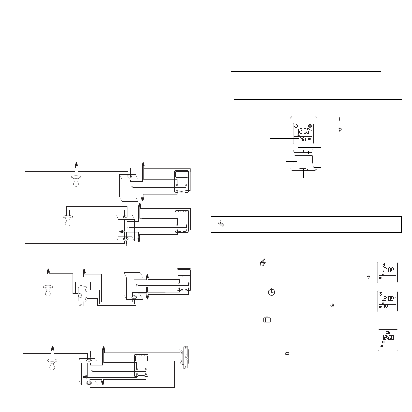
SINGLE-SWITCH INSTALLATION
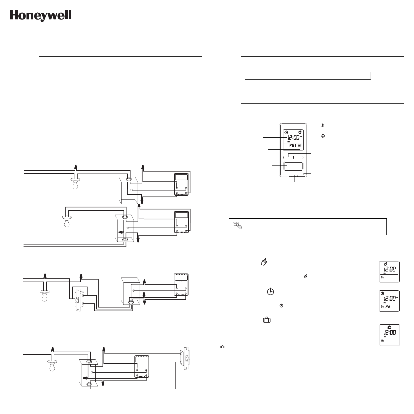
Connect the LINE and 3 WAY wires to the line (120 V) wire and LOAD wire to the load. Connect the GND
wire to a ground screw inside the electrical box.
EXISTING 3-WAY INSTALLATION
Connect the LOAD wire on the RPLS540A/RPLS541A to the “common” wire, which you identified when
removing the old switch. Connect the GND wire to a ground screw inside the electrical box. Connect the LINE
and 3-WAY wires to the two remaining wires. At the other 3-way switch, connect the jumper wire between the
“common” screw and the screw where the LINE wire of the RPLS540A/RPLS541A is connected.
NEW 3-WAY INSTALLATION
The RPLS540A/RPLS541A will turn the lights on at sunset and turn them off at 11:00 pm by default. If these
settings are appropriate for you, you only need to set the time and date (see shaded zone in the menu
flowchart sheet). If the switch’s sunset time does not correspond to the actual sunset time, see sections 5.3.3
and 5.3.4.
5.1 Mode Menu
Use the Mode menu to select one of the three modes of operation (see sections 5.1.1 to 5.1.3).
5.1.1 Manual Mode
In Manual mode, the RPLS540A/RPLS541A operates like a regular switch. To turn the
lights on or off, briefly press the main button. The icon appears when the switch is in
Manual mode.
5.1.2 Automatic Mode
In Automatic mode, the RPLS540A/RPLS541A turns the lights on or off according to the
set programs (see Section 5.4). The icon as well as the current program number are
displayed.
5.1.3 Random Mode
In Random mode, the RPLS540A/RPLS541A has no specific times to turn the lights on or
off. This mode is designed to give the impression the house is occupied during your
absence. It is similar to the Automatic mode except there is no fixed program. The
programs are automatically set to different times by the RPLS540A/RPLS541A every day.
The icon appears when the switch is in Random mode.
The first “On” program occurs at sunset. Each “On” program lasts between 1 hour and 1
hour and 30 minutes; each “Off” program lasts between 15 and 30 minutes. The last “Off”
program occurs between 10:30 pm and midnight.
5.1.4 Temporary Override
When the RPLS540A/RPLS541A is in Automatic or Random mode, you can press the main button at any
time to override the default state for the current program. The lights will turn off if they are on and vice versa.
The icon (On or Off) of the new state flashes to indicate that the state is temporary. The new state is
maintained until you press the main button again or till the next “On” or “Off” program.
Applications
1.
• Incandescent • Halogen • Low-voltage halogen with transformer • Fluorescent
Installation
2.
black
white
black (LINE)
black (LOAD)
green (GND)
yellow (3-WAY)
120
VAC
120
VAC
black
white
black
white
black
white
black (LINE)
black (LOAD)
green (GND)
yellow (3-WAY)
120
VAC
jumper
three-way
switch
black (LINE)
black (LOAD)
green (GND)
yellow (3-WAY)
black
white
black
white
black
white
red
120
VAC
black (LINE)
black (LOAD)
green (GND)
yellow (3 WAY)
single-pole
switch
black
white
black
white
white
black
Quick Start-up
3.
Set the time and date before using the switch for the first time.
Operation
4.
Setup Menus
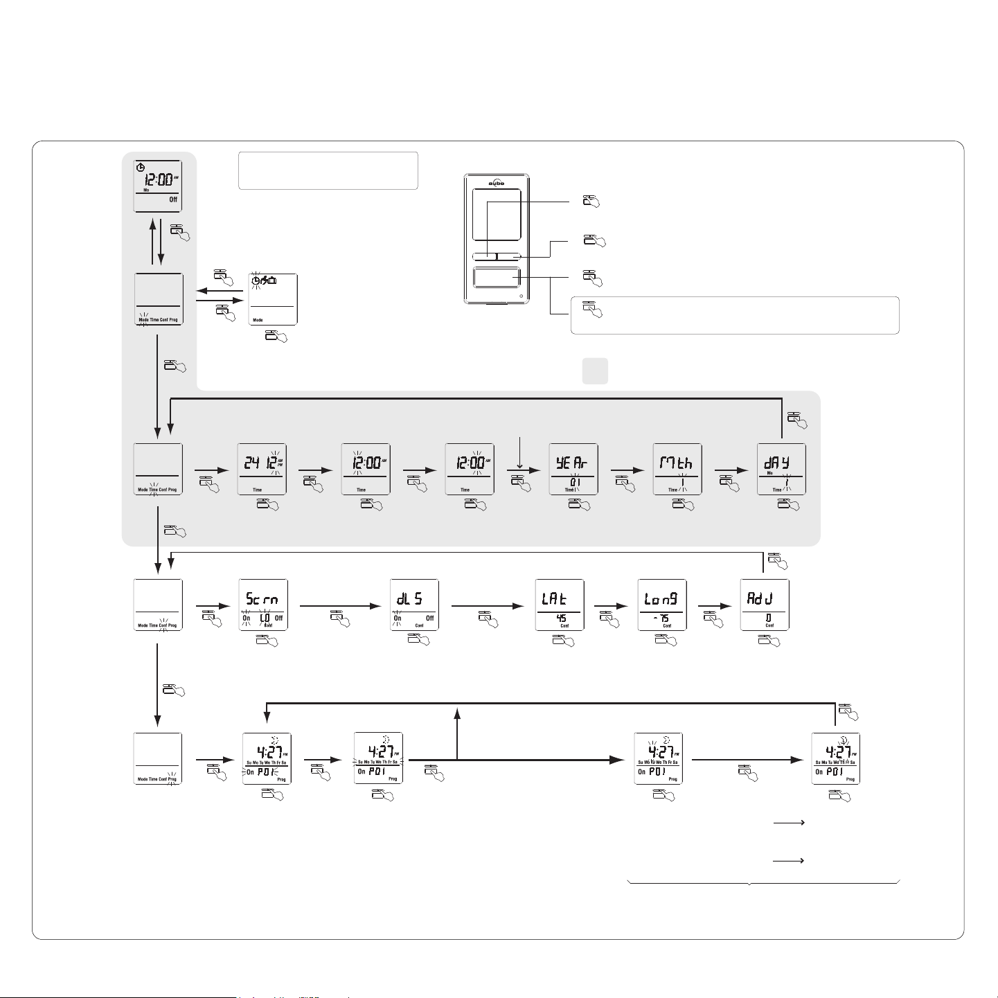
5.
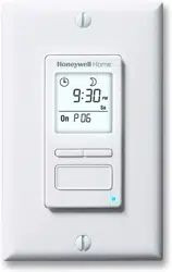
Press the main button for 3 seconds to enter the setup menus. Refer to
the menu flowchart sheet on how to navigate the menus.
The icon indicates the current program
has been activated at sunset.
The icon indicates the current program
has been activated at sunrise.
The LED illuminates when the load state is on.
Briefly press this button to turn the
lights on or off. See “Temporary
Override” in Section 5.1.4.
Press for 3 seconds to enter the
setup menus.
Indicates the mode of
operation (see Section 5.1)
Indicates the current program
Press this button to display today’s sunrise time.
Press this button to display today’s sunset time.
Safety switch
Before replacing a light bulb, pull out to disconnect power to the switch. This prevents, while the bulb is
out, any possible short circuit which will damage the switch. Push back in after the light bulb is replaced.
Indicates the load on/off state
Indicates the time and day
(3 sec.)
RPLS540A/RPLS541A
User guide
7-day Solar Programmable Wall Switch
69-2454EFS-01_400-070-004-A (TI070_RPLS540A) USA.book Page 1 Tuesday, May 18, 2010 10:55 AM
RPLS540A/RPLS541A 2/8
5.2 Time Menu
The time display flashes on the screen when the time has not yet been
set or after a 4-hour power outage. Use the Time menu to select the
time format (12-hour or 24-hour) and to set the clock and date.
NOTE: The date is used to determine the sunset and sunrise times.
5.3 Configuration Menu (Conf)
Use the Configuration menu to set the following parameters (see
sections 5.3.1 to 5.3.4).
5.3.1 Backlight mode (SCRN)
The screen is lit at high intensity for 8 seconds when you press any
button. The rest of the time, depending on the backlight mode
selected, the screen behaves as follows:
Scrn Off: The screen is not lit.
Scrn On HI: The screen is lit at high intensity.
Scrn On LO: The screen is lit at low intensity (default mode).
5.3.2 Automatic Daylight Savings Time Changeover (
DLS
)
When automatic daylight savings time changeover is on (DLS On), the
RPLS540A/RPLS541A changes to daylight savings time (summer
time) at 2:00 am on the second Sunday of March and changes back to
normal time (winter time) at 2:00 am on the first Sunday of November.
This function is enabled (DLS On) by default.
5.3.3 Latitude and Longitude Coordinates (
LAT and LONG
)
The coordinates are used to turn the lights on at sunset and off at sun-
rise. The latitude is set to +45 and longitude to -75 by default. These
settings provide approximate sunset and sunrise times for most North
American cities. To obtain your city’s coordinates (or those of a nearby
city), see the coordinates table. You can also obtain this information at
www.geonames.org or with a Global Positioning System (GPS)
device. The accuracy of the sunset and sunrise times depends on the
accuracy of the coordinates you enter for your city.
NOTE: Enter a negative value for a south latitude or a west longitude.
5.3.4 Correction Factor (ADJ)
If your city’s time zone is based on political or economic boundaries
instead of its coordinates, your lights might switch on or off too early or
too late with respect to sunrise and sunset. In this case, apply a
correction factor (+1 or -1 hour; refer to addendum). Otherwise, leave
it at 0 (default value).
5.4 Program Menu (Prog)
Use the Program menu to set the programs; i.e. the times you want
the lights to turn On or Off when the switch is in Automatic mode. To
set a program, proceed as follows:
Select a program number (see section 5.4.1)
Set the day(s) of the program (see section 5.4.2)
Set the program start time (see section 5.4.3)
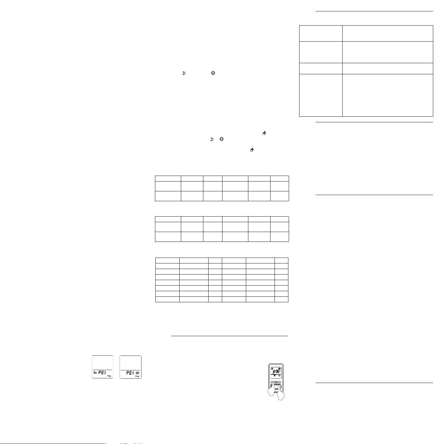
5.4.1 Selecting a program number
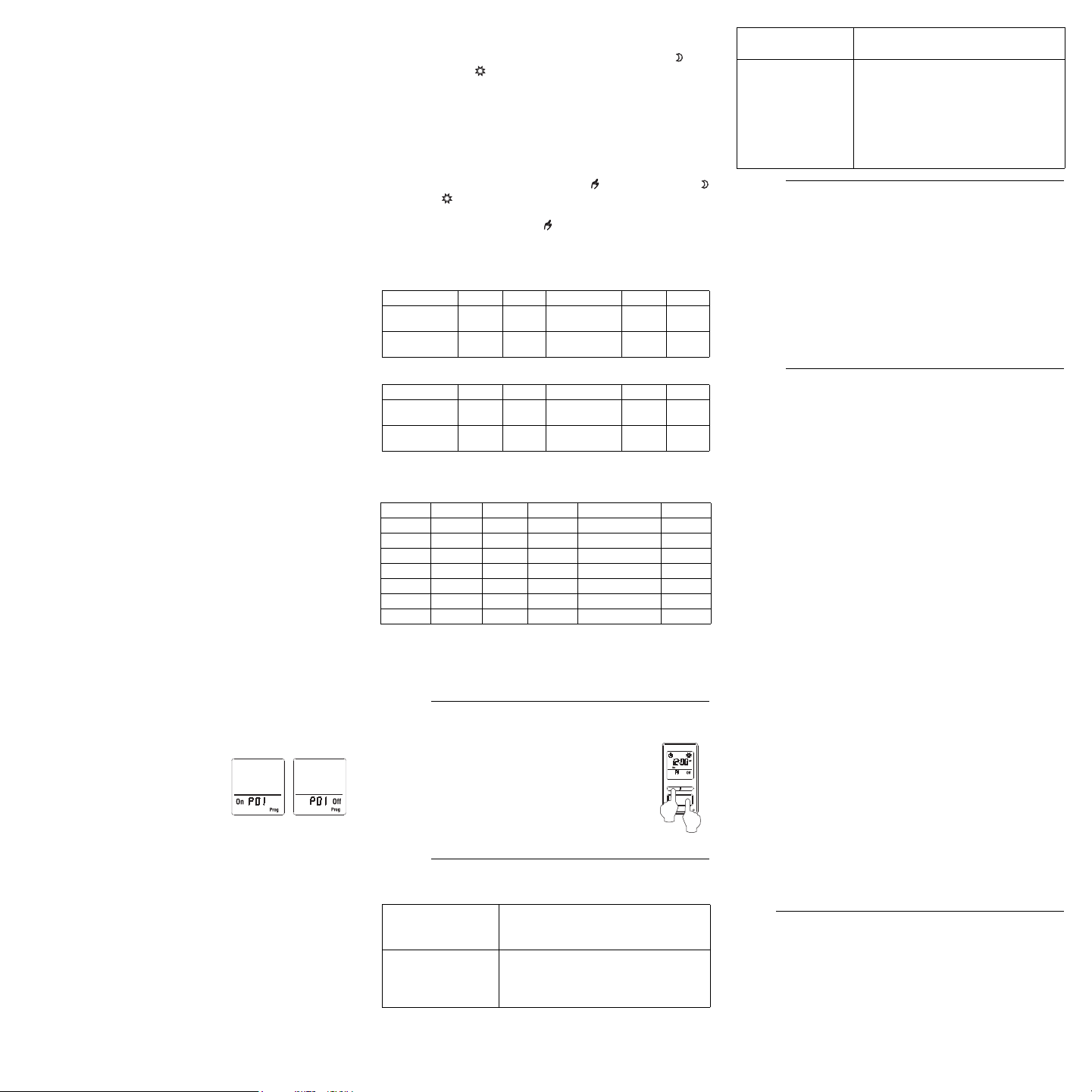
You can set up to 7 “On” programs
(“P01 On” to “P07 On”) and 7 “Off”
programs (“P01 Off” to “P07 Off”).
Select an “On” program to set when to
turn the lights on. Select an “Off”
program to set when to turn the lights
off.
5.4.2 Setting the day(s) of the program
After selecting a program, set the day(s) of the program. You can
select a specific day, all 7 days or “none”. Choose “none” for any
unused program.
5.4.3 Setting the program start time
After setting the day(s) of the program, set its start time. You can
select either a specific time, the sunset time or the sunrise time:
• To select a specific time:
(1) Advance to the hour setting and select the hour.
(2) Advance to the minutes setting and select the minutes.
• To select sunset or sunrise time:
(1) Advance to the hour setting and select the sunset time or
sunrise time. (
When you scroll, the sunset time
and
sunrise time
appear between 11 pm and 12 am
.)
(2) To enter an offset (from -70 to +70 minutes in 10-minute
increments) between the sunset or sunrise time and the
program start time, advance to the minutes setting and change
the minutes.
• EXAMPLE: If the sunset time is 6:13 pm and you change the
minutes to display 6:43 pm, you have entered a delay of 30
minutes. If, later in the year, the sunset time is 4:01 pm, the
program will start at 4:31 pm.
• NOTE: When you enter an offset, appears along with
or when you display the sunset or sunrise time. To
remove the offset, display the sunset or sunrise time and
change the minutes until disappears.
5.4.4 Examples
Example 1: The lights turn on at sunset and off at 11:00 pm every day
(default setting).
Example 2: The lights turn on at sunset and off at sunrise every day.
Example 3: The lights turn on at 8:00 pm every day and turn off at
10:00 pm every day except on Saturday night when they turn off at
1:00 am.
Be careful about overlapping!
For example, if you set “P01 Off” at 10:00 pm for all 7 days and set
“P02 Off” to 11:00 pm for Saturday, on Saturday, the lights will turn off
at 10:00 pm, not 11:00 pm since “P01 Off” is set to an earlier time than
“P02 Off”.
To return the switch to its default settings,
simultaneously press both main and left buttons and
hold. The software version will appear for 5 seconds.
RST will appear for the next 5 seconds. Release the
buttons when all segments appear on the screen. The
switch is now reset (see default settings in the menu
flowchart).
Supply: 120 VAC, 60 Hz
Minimum load: 40 watts
Maximum load: 500 watts
Operating temperature range: -15 °C to 50 °C (5 °F to 122 °F)
Storage temperature range: -40 °C to 60 °C (-40 °F to 140 °F)
Power outage: The screen is blank. Only the time must be set if the
outage lasts more than 4 hours; all other settings and programs are
permanently saved
Latitude range: from -65° to +65°
Solar table precision: +/- 11 min. (within ±60° latitude)
Certification: UL (c UL us)
Honeywell warrants this product, excluding battery, to be free from
defects in the workmanship or materials, under normal use and ser-
vice, for a period of one (1) year from the date of purchase by the con-
sumer. If at any time during the warranty period the product is
determined to be defective or malfunctions, Honeywell shall repair or
replace it (at Honeywell's option).
If the product is defective,
(i) return it, with a bill of sale or other dated proof of purchase, to
the place from which you purchased it, or
(ii) call Honeywell Customer Care at 1-800-468-1502. Customer
Care will make the determination whether the product should be
returned to the following address: Honeywell Return Goods,
Dock 4 MN10-3860, 1885 Douglas Dr N, Golden Valley, MN
55422, or whether a replacement product can be sent to you.
This warranty does not cover removal or reinstallation costs. This war-
ranty shall not apply if it is shown by Honeywell that the defect or mal-
function was caused by damage which occurred while the product was
in the possession of a consumer.
Honeywell's sole responsibility shall be to repair or replace the product
within the terms stated above. HONEYWELL SHALL NOT BE LIABLE
FOR ANY LOSS OR DAMAGE OF ANY KIND, INCLUDING ANY
INCIDENTAL OR CONSEQUENTIAL DAMAGES RESULTING,
DIRECTLY OR INDIRECTLY, FROM ANY BREACH OF ANY WAR-
RANTY, EXPRESS OR IMPLIED, OR ANY OTHER FAILURE OF
THIS PRODUCT. Some states do not allow the exclusion or limitation
of incidental or consequential damages, so this limitation may not
apply to you.
THIS WARRANTY IS THE ONLY EXPRESS WARRANTY HONEY-
WELL MAKES ON THIS PRODUCT. THE DURATION OF ANY
IMPLIED WARRANTIES, INCLUDING THE WARRANTIES OF MER-
CHANTABILITY AND FITNESS FOR A PARTICULAR PURPOSE, IS
HEREBY LIMITED TO THE ONE-YEAR DURATION OF THIS WAR-
RANTY. Some states do not allow limitations on how long an implied
warranty lasts, so the above limitation may not apply to you.
This warranty gives you specific legal rights, and you may have other
rights which vary from state to state.
If you have any questions concerning this warranty, please write Hon-
eywell Customer Relations, 1985 Douglas Dr, Golden Valley, MN
55422 or call 1-800-468-1502. In Canada, write Retail Products
ON15-02H, Honeywell Limited/Honeywell Limitée, 35 Dynamic Drive,
Scarborough, Ontario M1V4Z9.
If you have any questions about your light switch, go to
http://yourhome.honeywell.com, or call Honeywell Customer Care
toll-free at 1-800-468-1502.
“P01 On” “P01 Off”
Program Days Time Program Days Time
P01 On All 7
days
sunset P01 Off All 7
days
11:00
pm
P02 On to
P07 On
None — P02 Off to
P07 Off
None —
Program Days Time Program Days Time
P01 On All 7
days
sunset P01 Off All 7
days
sunrise
P02 On to
P07 On
None — P02 Off to
P07 Off
None —
Program Days Time Program Days Time
P01 On All 7 days 8:00 pm P01 Off Sunday (Su) 10:00 pm
P02 On None — P02 Off Monday (Mo) 10:00 pm
P03 On None — P03 Off Tuesday (Tu) 10:00 pm
P04 On None — P04 Off Wednesday (We) 10:00 pm
P05 On None — P05 Off Thursday (Th) 10:00 pm
P06 On None — P06 Off Friday (Fr) 10:00 pm
P07 On None — P07 Off Sunday (Su) 1:00 am
Reset to Default Settings
6.
Troubleshooting
7.
The screen is blank. • A light bulb is burned out.
• The safety switch is pulled out (see
section 4).
The display is faded
or irregular.
• The load is less than 40 W.
• The ambient temperature is either
below or above the switch’s operating
temperature.
The metal plate is hot. This is normal with high loads (maximum
of 500 W).
The sunset or sunrise
time is inaccurate.
• The date or time is wrong
(see section 5.2).
• The longitude or latitude is wrong
(see section 5.3.3).
• The correction factor is wrong
(see section 5.3.4).
• You have entered an offset
(see section 5.4.3).
Specifications
8.
Warranty
9.
Customer Assistance
10.
69-2454EFS-01_400-070-004-A (TI070_RPLS540A) USA.book Page 2 Tuesday, May 18, 2010 10:55 AM

RPLS540A/RPLS541A 3/8
RPLS540A/RPLS541A
Guide de l’utilisateur
Interrupteur mural programmable — solaire et 7 jours
L’interrupteur RPLS540A/RPLS541A peut être utilisé aussi bien pour une installation conventionnelle que
pour une installation à 3 voies avec les types d’éclairage suivants :
Le RPLS540A/RPLS541A ne peut être utilisé pour une charge inférieure à 40 W ou supérieure à 500 W.
Mettre le circuit hors tension à partir du disjoncteur afin d'éviter tout risque de choc électrique.
Enlever l’interrupteur existant (pour une installation à 3 voies, identifier et marquer le fil relié à la borne
« commun »).
Installer le nouvel interrupteur (voir la section appropriée ci-dessous).
Remettre le circuit sous tension à partir du disjoncteur.
MISE EN GARDE : Mettre l’interrupteur hors tension lorsque vous remplacez une ampoule (voir la
section 4).
INSTALLATION CONVENTIONNELLE
Relier les fils « LINE » et « 3-WAY » à la ligne 120 Vca et le fil « LOAD » à la charge. Relier le fils « GND » à
la vis de mise à la terre dans la boite électrique.
INSTALLATION EXISTANTE À 3 VOIES
Relier le fil « LOAD » du RPLS540A/RPLS541A au fil « commun » identifié lorsque vous avez enlevé
l’ancien interrupteur. Relier le fils « GND » à la vis de mise à la terre dans la boite électrique. Relier les fils «
LINE » et « 3-WAY » aux deux fils restants. Pour l’autre interrupteur à 3 voies, relier le fil de raccord (fourni)
entre la borne « commun » et la borne sur laquelle le fil « LINE » du RPLS540A/RPLS541A est relié.
NOUVELLE INSTALLATION À 3 VOIES
Le RPLS540A/RPLS541A allumera les lumières au coucher du soleil et les éteindra à 23h par défaut. Si ces
réglages vous conviennent, vous n’avez qu’à régler l’heure et la date (voir la case grise dans la feuille de
l’organigramme des menus). Si l’heure du coucher du soleil de l’interrupteur diffère de l’heure réelle du
coucher du soleil, voir les sections 5.3.3 et 5.3.4.
5.1 Menu Mode
Vous pouvez utiliser le menu Mode pour sélectionner l’un des trois modes de fonctionnement (voir les
sections 5.1.1 à 5.1.3).
5.1.1 Mode Manuel
En mode Manuel, le RPLS540A/RPLS541A fonctionne comme un interrupteur
conventionnel. Pour allumer ou éteindre les lumières, appuyer brièvement sur la touche
principale. L’icône apparaît lorsque l’interrupteur est en mode Manuel.
5.1.2 Mode Automatique
En mode Automatique, le RPLS540A/RPLS541A allume et éteint les lumières selon les
programmes réglées (voir la section 5.4). L’icône ainsi que le numéro du programme en
cours sont affichés.
5.1.3 Mode Aléatoire
En mode Aléatoire, le RPLS540A/RPLS541A n’a pas de moment précis pour allumer ou
éteindre les lumières. Ce mode sert à donner l’impression que votre résidence est occupée
pendant votre absence. Il est semblable au mode Automatique, sauf qu’il n’y a pas de
programme fixe. Les programmes sont automatiquement réglés chaque jour par le
RPLS540A/RPLS541A à des heures différentes. L’icône apparaît lorsque l’interrupteur
est en mode Aléatoire.
Le premier programme « Marche » se produit au coucher du soleil. Chaque programme
« Marche » dure entre 1 heure et 1 heure et demie, et chaque programme « Arrêt » dure
entre 15 et 30 minutes. Le dernier programme « Arrêt » se produit entre 22h30 et minuit.
5.1.4 Dérogation temporaire
Lorsque le RPLS540A/RPLS541A est en mode Automatique ou Aléatoire, vous pouvez, en tout temps,
appuyer sur la touche principale pour déroger à l’état en cours; les lumières s’éteindront si elles sont
Applications
1.
• Incandescent • Halogène • Halogène basse tension avec transformateur • Fluorescent
Installation
2.
120
Vca
120
Vca
noir (LOAD)
jaune (3-WAY)
vert (GND)
noir (LINE)
noir (LOAD)
jaune (3-WAY)
vert (GND)
noir (LINE)
noir
blanc
noir
blanc
noir
blanc
noir
blanc
noir (LOAD)
jaune (3-WAY)
noir
blanc
rouge
120
Vca
cavalier
interrupteur
à trois voies
vert (GND)
noir (LINE)
noir
blanc
noir
blanc
120
Vca
interrupteur
unipolaire
noir (LOAD)
jaune (3-WAY)
vert (GND)
noir (LINE)
noir
blanc
noir
blanc
noir
blanc
Démarrage rapide
3.
Régler l’heure et la date avant d’utiliser l’interrupteur pour la première fois.
Fonctionnement
4.
Menus de réglage
5.
Appuyer sur la touche principale pendant 3 secondes pour entrer dans les menus. Consulter
la feuille de l’organigramme des menus pour savoir comment naviguer dans les menus.
Le témoin s’allume lorsque l’état de la
charge est à “Marche” (On).
Appuyer brièvement sur cette touche
pour allumer ou éteindre les lumières.
Voir “Dérogation temporaire” dans la
section 5.1.4.
Appuyer pendant 3
secondes pour entrer dans les menus.
Indique le mode de
fonctionnement (voir section 5.1)
Indique le programme en cours
Appuyer sur cette touche pour afficher
l’heure du lever du soleil d’aujourd’hui.
Commutateur de sécurité
Avant de remplacer une ampoule, tirer sur la languette pour mettre l’interrupteur hors tension.
Ceci prévient, lorsque l’ampoule est enlevée, tout risque de court-circuit qui pourrait
endommager l’interrupteur. Une fois l’ampoule remplacée, replacer la languette.
Indique l’état marche/arrêt (On/Off)
de la charge
Indique l’heure et le jour
L’icône indique que le programme en
cours a été activé au coucher du soleil.
L’icône indique que le programme
en cours a été activé au lever du soleil.
Appuyer sur cette touche pour afficher
l’heure du coucher du soleil d’aujourd’hui.
(3 sec.)
69-2454EFS-01_400-070-004-A (TI070_RPLS540A) USA.book Page 3 Tuesday, May 18, 2010 10:55 AM
RPLS540A/RPLS541A 4/8
allumées et vice versa. L’icône (On ou Off) du nouvel état clignote
pour indiquer que l’état est temporaire. Le nouvel état est maintenu
jusqu’à ce qu’on appuie de nouveau sur la touche principale ou
jusqu’au prochain programme « Marche » (On) ou « Arrêt » (Off).
5.2 Menu Heure (Time)
L’affichage de l’heure clignote à l’écran lorsque l’heure n’est pas
encore réglée ou après une panne de courant de plus de 4 heures.
Utiliser le menu Heure pour sélectionner le format d’heure ainsi que
pour régler l’horloge et la date.
NOTA : La date sert à déterminer l’heure du coucher du soleil et celle
du lever du soleil.
5.3 Menu Configuration (Conf)
Utiliser le menu Configuration pour régler les paramètres suivants
(voir les sections 5.3.1 à 5.3.4).
5.3.1 Mode de rétroéclairage (SCRN)
L'écran est allumé à haute intensité pendant 8 secondes lorsque vous
appuyez sur un bouton. Le reste du temps, selon le mode de
rétroéclairage choisi, l'écran se comporte comme suit :
Scrn Off : L’écran n’est pas éclairé.
Scrn On HI : L’écran est éclairé à haute intensité.
Scrn On LO : L’écran est éclairé à basse intensité (mode par défaut).
5.3.2 Passage automatique à l’heure avancée (DLS)
Quand le passage automatique à l’heure avancée est activé (DLS
On), le RPLS540A/RPLS541A passe à l’heure avancée (heure d'été)
à 2h le deuxième dimanche de mars et passe à l’heure normale
(heure d'hiver) à 2h le premier dimanche de novembre. La fonction
est activée (DLS On) par défaut.
5.3.3 Latitude et longitude (LAT et LONG)
Les coordonnées servent à allumer les lumières au coucher du soleil
et les éteindre au lever du soleil. Par défaut, la latitude est à +45 et la
longitude est à -75. Ces réglages offrent des heures approximatives
de coucher et de lever du soleil pour la plupart des villes nord-améri-
caines. Pour obtenir les coordonnées de votre ville (ou celles d’une
ville avoisinante), consulter la table des coordonnées. Cette informa-
tion peut aussi être obtenue au www.geonames.org ou avec un sys-
tème de navigation (GPS). L’exactitude de l’heure du coucher du soleil
et de l’heure du lever du soleil dépend de l’exactitude des coordon-
nées que vous avez enregistré pour votre ville.
NOTA : Inscrire une valeur négative pour une valeur de latitude sud
ou une valeur de longitude ouest.
5.3.4 Facteur de correction (ADJ)
Si le fuseau horaire de votre ville est basé sur des frontières politiques
ou économiques plutôt que sur ses coordonnées, vos lumières
pourraient s’allumer or s’éteindre trop tôt ou trop tard par rapport au
lever ou coucher du soleil. Dans ce cas, inscrire un facteur de
correction (+1 ou -1 heure, consulter le supplément). Sinon, le laisser
à 0 (valeur par défaut).
5.4 Menu Programme (Prog)
Utiliser le menu Programme pour régler les programmes; c.à.d. les
heures auxquelles vous voulez que les lumières s’allument ou
s’éteignent lorsque l’interrupteur est en mode Automatique. Pour
régler un programme, procéder comme suit :
Sélectionner un numéro de programme (voir la section 5.4.1)
Sélectionner le(s) jour(s) du programme (voir la section 5.4.2)
Régler l’heure du début du programme (voir la section 5.4.3)
5.4.1 Sélectionner un numéro de programme
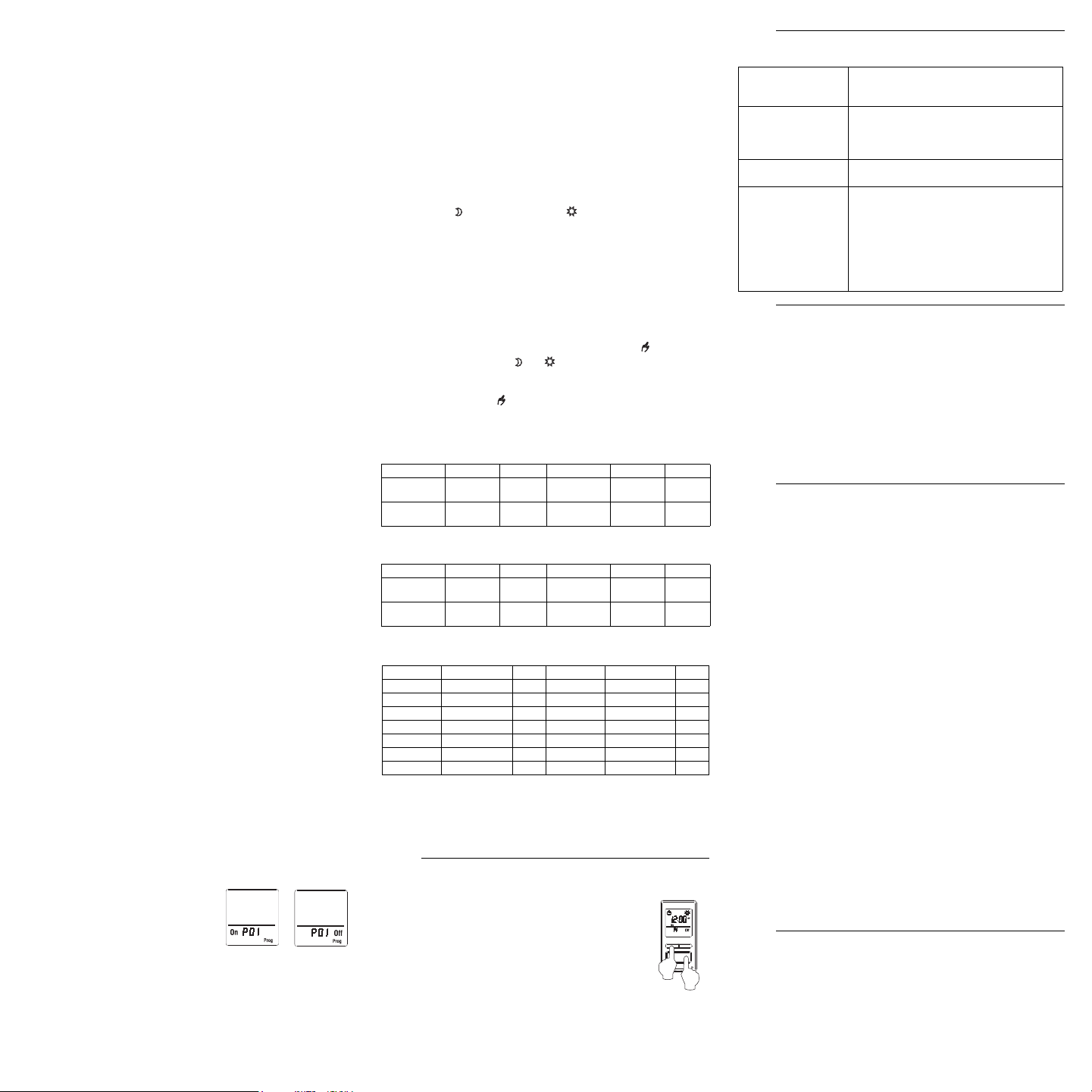
Vous pouvez enregistrer jusqu’à 7
programmes « Marche » (« P01 On »
à « P07 On ») et 7 programmes
« Arrêt » (« P01 Off » à « P07 Off »).
Sélectionner un programme « Marche »
à laquelle régler l’heure pour allumer les
lumières. Sélectionner un programme
« Arrêt » à laquelle régler l’heure pour
éteindre les lumières.
5.4.2 Régler le jour du programme
Une fois le programme sélectionné, régler le jour du programme. Vous
pouvez sélectionner un jour spécifique, les 7 jours ou « aucun »
(none). Choisir « aucun » pour les programmes non utilisés.
5.4.3 Régler l’heure du début du programme
Après avoir réglé le jour du programme, régler l’heure du début. Vous
pouvez sélectionner une heure spécifique, l’heure du coucher du
soleil ou l’heure du lever du soleil.
• Pour sélectionner une heure spécifique :
(1) Avancer au réglage d’heure et sélectionner l’heure.
(2) Avancer au réglage des minutes et sélectionner les minutes.
• Pour sélectionner le coucher ou le lever du soleil :
(1) Avancer au réglage d’heure et sélectionner le coucher ou le
lever du soleil. (Lorsque vous faites défiler les heures, le
coucher et le lever du soleil apparaissent entre 23h et
0h.)
(2) Pour programmer un écart (de -70 à +70 minutes par
intervalles de 10 minutes) entre le coucher ou lever du soleil et
l’heure du début du programme, avancer au réglage des
minutes et changer les minutes.
• EXEMPLE : Si le coucher du soleil est 18h13 et que vous
changez les minutes pour afficher 18h43, cela signifie que
vous avez programmé un délai de 30 minutes. Si, plus tard
dans l’année, le coucher du soleil est 16h01, le programme
débutera à 16h31.
• NOTA : Lorsque vous programmez un écart, apparaît en
même temps que ou quand vous affichez l’heure du
coucher ou lever du soleil. Pour enlever l’écart, afficher
l’heure du coucher ou lever du soleil et changer les minutes
jusqu’à ce que disparaisse.
5.4.4 Exemples
Exemple 1 : Chaque jour, les lumières s’allument au coucher du soleil
et s’éteignent à 23h (réglages par défaut).
Exemple 2 : Chaque jour les lumières s’allument au coucher du soleil
et s’éteignent au lever du soleil.
Exemple 3
: Les lumières s’allument à 20h chaque jour et s’éteignent à
22h chaque jour, sauf le samedi soir où elles s’éteignent à 1h.
Attention au chevauchement!
Si vous réglez « P01 Off » à 22h pour les 7 jours et vous réglez «P02
Off » à 23h pour le samedi, le samedi les lumières s’éteindront à 22h
et non 23h parce que « P01 Off » est réglé a une heure plus tôt que «
P02 Off ».
Pour remettre l’interrupteur aux réglages par défaut,
appuyer simultanément sur la touche principale et la
touche gauche et les maintenir enfoncées. La version
du logiciel apparaîtra à l’écran pendant 5 secondes,
suivie de RST pendant 5 autres secondes. Relâcher les
touches lorsque tous les segments s’affichent à l’écran.
L’interrupteur est maintenant réinitialisé (voir les
réglages par défaut dans le diagramme de
programmation).
Alimentation : 120 VAC, 60 Hz
Charge minimale : 40 watts
Charge maximale : 500 watts
Température de fonctionnement : -15 °C à 50 °C (5 °F à 122 °F)
Température d’entreposage : -40 °C à 60 °C (-40 °F à 140 °F)
Panne de courant : L'écran est éteint. Seule l’heure doit être réglée si
la panne dure plus de 4 heures; les autres réglages et les
programmes sont conservés de façon permanente.
Plage de latitude : de -65° à +65°
Précision du tableau solaire
: +/- 11 min. (latitudes inférieures à ±60°)
Certification : UL (c UL us)
Honeywell garantit ce produit, à l'exception des piles, contre tout vice de fabrication
ou de matière dans la mesure où il en est fait une utilisation et un entretien
convenables, et ce, pour un (1) an à partir de la date d'achat par le consommateur. En
cas de défectuosité ou de mauvais fonctionnement pendant la période de garantie,
Honeywell remplacera ou réparera le produit (au gré de Honeywell).
Si le produit est défectueux,
(i) le retourner, accompagné d'une preuve d'achat indiquant la date d'achat, à
l’endroit où il a été acheté, ou
(ii) s'adresser au Service à la clientèle de Honeywell en composant le 1-800-468-
1502. Le Service à la clientèle déterminera alors si le produit doit être retourné
à l'adresse suivante : Honeywell Return Goods, Dock 4 MN10-3860, 1885
Douglas Dr N, Golden Valley, MN 55422, ou si un produit de remplacement
peut vous être expédié.
La présente garantie ne couvre pas les frais de retrait ou de réinstallation. La
présente garantie ne s'appliquera pas s'il est démontré que la défectuosité ou le
mauvais fonctionnement est dû à un endommagement du produit alors que le
consommateur l'avait en sa possession.
La responsabilité de Honeywell se limite à réparer ou à remplacer le produit
conformément aux modalités susmentionnées. HONEYWELL N'EST EN AUCUN
CAS RESPONSABLE DES PERTES OU DOMMAGES, Y COMPRIS LES
DOMMAGES INDIRECTS OU ACCESSOIRES DÉCOULANT DIRECTEMENT OU
INDIRECTEMENT D'UNE VIOLATION QUELCONQUE D'UNE GARANTIE,
EXPRESSE OU TACITE, APPLICABLE AU PRÉSENT PRODUIT NI DE TOUTE
AUTRE DÉFECTUOSITÉ DU PRÉSENT PRODUIT. Certaines provinces ne
permettent pas l'exclusion ou la restriction des dommages indirects et, par
conséquent, la présente restriction peut ne pas s'appliquer.
LA PRÉSENTE GARANTIE TIENT LIEU DE TOUTES LES AUTRES GARANTIES,
EXPRESSES OU TACITES, ET LES GARANTIES DE VALEUR MARCHANDE ET
DE CONFORMITÉ À UNE FIN PARTICULIÈRE SONT PAR LES PRÉSENTES
EXCLUES APRÈS LA PÉRIODE DE UN AN DE LA PRÉSENTE GARANTIE
Certaines provinces ne permettent pas de limiter la durée des garanties tacites et, par
conséquent, la présente limitation peut ne pas s'appliquer.
La présente garantie donne au consommateur des droits légaux spécifiques et peut-
être certains autres droits qui peuvent varier d'une province à l'autre.
Pour toute question concernant la présente garantie, prière d'écrire au Service à la
clientèle de Honeywell à l'adresse suivante : Honeywell Customer Relations, 1985
Douglas Drive, Golden Valley, MN 55422, ou encore composer le 1-800-468-1502.
Au Canada, prière de s'adresser au service des Produits de détail, Honeywell
Limited/Honeywell Limitée, 35, Dynamic Drive, Scarborough (Ontario) M1V 4Z9.
Si vous avez des questions sur le fonctionnement de votre interrupteur
programmable, veuillez consulter
http://yourhome.honeywell.com
, ou
vous adresser au Service à la clientèle de Honeywell en composant
sans frais le
1-800-468-1502
.
« P01 On » « P01 Off »
Programme Jours Heure Programme Jours Heure
P01 On les 7 jours coucher
du soleil
P01 Off les 7 jours 23h
P02 On à
P07 On
aucun — P02 Off à
P07 Off
aucun —
Programme Jours Heure Programme Jours Heure
P01 On les 7 jours coucher
du soleil
P01 Off les 7 jours lever
du soleil
P02 On à
P07 On
aucun — P02 Off à
P07 Off
aucun —
Programme Jours Heure Programme Jours Heure
P01 On les 7 jours 20h P01 Off dimanche (Su) 22h
P02 On aucun — P02 Off lundi (Mo) 22h
P03 On aucun — P03 Off mardi (Tu) 22h
P04 On aucun — P04 Off mercredi (We) 22h
P05 On aucun — P05 Off jeudi (Th) 22h
P06 On aucun — P06 Off vendredi (Fr) 22h
P07 On aucun — P07 Off dimanche (Su) 1h
Réinitialisation aux réglages par défaut
6.
Problèmes et solutions
7.
L’écran est vide. • Une ampoule est brûlée.
• Le commutateur de sécurité est retiré
(voir la section 4).
L’affichage est pâle
ou irrégulier.
• La charge est inférieure à 40 W.
• La température ambiante est inférieure
ou supérieure à la température de
fonctionnement de l’interrupteur.
La plaque métallique
est chaude.
Ceci est normal lorsque la charge est éle-
vée (maximum de 500 W).
L’heure du coucher
ou du lever du soleil
est inexacte.
• La date ou l’heure est incorrecte
(voir la section 5.2).
• La longitude ou la latitude est incorrecte
(voir la section 5.3.3).
• Le facteur de correction est incorrect
(voir la section 5.3.4).
• Vous avez programmé un écart
(voir la section 5.4.3).
Fiche technique
8.
Garantie
9.
Service à la clientèle
10.
69-2454EFS-01_400-070-004-A (TI070_RPLS540A) USA.book Page 4 Tuesday, May 18, 2010 10:55 AM
RPLS540A/RPLS541A 5/8
RPLS540A/RPLS541A
Guía del usuario
Interruptor mural programable solar de 7 días
El interruptor programable RPLS540A/RPLS541A puede usarse tanto para una instalación estándar como
para una instalación de tres vías con los siguientes tipos de iluminación:
El RPLS540A/RPLS541A no se puede usar con una carga inferior a 40 W o superior a 500 W.
Desconectar el circuito desde el interruptor automático para evitar todo riesgo de electrocución.
Retirar el interruptor existente (para una instalación de tres vías, identificar y marcar el cable
conectado al terminal “común”).
Instalar el nuevo interruptor (ver la sección apropiada más abajo).
Reconectar el circuito desde el interruptor automático.
ATENCIÓN: desconectar el interruptor cuando haya que reemplazar una bombilla (ver la sección 4).
INSTALACIÓN ESTÁNDAR
Conectar los cables “LINE” y “3 WAY” a la línea de 120 VCA y el cable “LOAD” a la carga. Conectar el cable
“GND” al terminal de puesta a tierra en la caja de electricidad.
INSTALACIÓN EXISTENTE DE 3 VÍAS
Conectar el cable “LOAD” del RPLS540A/RPLS541A al cable “común”, identificado cuando se retiró el antiguo
interruptor. Conectar el cable “GND” al tornillo de puesta a tierra en la caja de electricidad. Conectar los cables
“LINE” y “3 WAY” a los dos cables restantes. En el otro interruptor de 3 vías, conectar el cable de puente (provisto)
entre el terminal “común” y el terminal en el que está conectado el cable “LINE” del RPLS540A/RPLS541A.
NUEVA INSTALACIÓN DE 3 VÍAS
El RPLS540A/RPLS541A encenderá las luces a la puesta de sol y las apagará a las 23 horas por defecto. Si
este horario no fuera conveniente, sólo hay que ajustar la hora y la fecha (ver el cuadro gris en el
organigrama de los menús). Si la hora programada de la puesta de sol del conmutador difiere de la hora
real, ver las secciones 5.3.3 y 5.3.4.
5.1 Menú Modo (Mode)
Se puede utilizar el menú Modo para seleccionar uno de los tres modos de funcionamiento (ver las
secciones 5.1.1 a 5.1.3).
5.1.1 Modo Manual
En modo Manual, el RPLS540A/RPLS541A funciona como un interruptor convencional.
Presionar brevemente el botón principal para encender o apagar las luces. El ícono
aparece cuando el interruptor está en modo Manual.
5.1.2 Modo Automático
En modo Automático, el RPLS540A/RPLS541A enciende y apaga las luces según los progra-
mas establecidos (ver la sección 5.4). Aparecen en pantalla el ícono y el número del pro-
grama en curso.
5.1.3 Modo Aleatorio
En modo Aleatorio, el RPLS540A/RPLS541A está programado para encender y apagar las
luces arbitrariamente y no en un momento preciso. Este modo sirve para dar la impresión
de que la vivienda está ocupada en ausencia de los moradores. Es semejante al modo
Automático salvo por el hecho de que no tiene programa fijo. El RPLS540A/RPLS541A
ajusta los programas automáticamente cada día a horas diferentes. Cuando el interruptor
está en modo Aleatorio, aparece el ícono .
El primer programa “Encendido” (On) comienza a funcionar con la puesta de sol. Cada programa
“Encendido” dura entre 1 hora y 1:30 horas y cada programa “Apagado” (Off) dura entre 15 y 30 minutos. El
último programa “Apagado” se produce entre las 22:30 y medianoche.
5.1.4 Cancelación temporaria
Cuando el RPLS540A/RPLS541A está en modo Automático o Aleatorio, se puede presionar el botón principal
en cualquier momento para cancelar el estado en curso: las luces se apagarán si estaban encendidas y
Aplicación
1.
• Incandescente • Halógena • Halógena de baja tensión con transformador • Fluorescente
Instalación
2.
120
VCA
120
VCA
negro (LOAD)
amarillo (3 WAY)
verde (GND)
negro (LINE)
negro (LOAD)
amarillo (3 WAY)
verde (GND)
negro (LINE)
negro
blanco
negro
blanco
negro
blanco
negro
blanco
negro (LOAD)
amarillo (3 WAY)
negro
blanco
rojo
120
Vca
puente
interruptor
de tres vías
verde (GND)
negro (LINE)
negro
blanco
negro
blanco
120
Vca
interruptor
unipolar
negro (LOAD)
amarillo (3 WAY)
verde (GND)
negro (LINE)
negro
blanco
negro
blanco
blanco
negro
Encendido rápido
3.
Ajustar la hora y la fecha antes de utilizar el interruptor por primera vez.
Funcionamiento
4.
Menús de ajuste
5.
Presionar el botón principal durante 3 segundos para entrar en los menús. Para saber
cómo navegar en los mismos, ver el organigrama de los menús.
El LED se ilumina cuando el estado
de la carga está en “Encendido” (On).
Presionar brevemente este botón para
encender o apagar las luces. Ver
“Cancelación temporaria” en la
Sección 5.1.4.
Presionar durante 3 segundos para
entrar en los menús.
Indica el modo de funcionamiento
(ver la sección 5.1)
Indica el programa en curso
Interruptor de seguridad
Antes de reemplazar una bombilla hay que tirar de la lengüeta para desconectar el interruptor.
Se previene así todo riesgo de corto circuito cuando se retire la bombilla, lo que podría dañar el
interruptor. Una vez reemplazada la bombilla, empujar nuevamente la lengüeta hacia adentro.
Indica el estado de encendido/apagado
(On/Off) de la charge
Indica la hora y el día
El ícono indica que el programa en
curso se activó a la puesta de sol.
El ícono indica que el programa en
curso se activó a la salida del sol.
Presionar este botón para visualizar la hora
de la salida del sol del día de la fecha.
Presionar este botón para visualizar la hora
de la puesta del sol del día de la fecha.
(3 sec.)
69-2454EFS-01_400-070-004-A (TI070_RPLS540A) USA.book Page 5 Tuesday, May 18, 2010 10:55 AM
RPLS540A/RPLS541A 6/8
viceversa. El ícono (On u Off) del nuevo estado parpadea para indicar
que es temporario. El nuevo estado se mantiene hasta que se presione
nuevamente el botón principal o hasta el próximo programa
“Encendido” (On) o “Apagado” (Off).
5.2 Menú Hora (Time)
La hora parpadea en la pantalla cuando no está todavía ajustada o
luego de un corte de corriente de más de 4 horas. Utilizar el menú Hora
para seleccionar el formato de la hora y para ajustar el reloj y la fecha.
NOTA: la fecha sirve para determinar la hora de la puesta y de la
salida del sol.
5.3 Menú Configuración (Conf)
Utilizar el menú Configuración para ajustar los parámetros siguientes
(ver las secciones 5.3.1 a 5.3.4).
5.3.1 Modo de iluminación de fondo (SCRN)
La pantalla se ilumina con gran intensidad durante 8 segundos
cuando se presiona cualquier botón. El resto del tiempo, según el
modo de iluminación de fondo elegido, la pantalla hace lo siguiente:
Scrn Off: la pantalla no está iluminada.
Scrn On HI: la pantalla está iluminada con gran intensidad.
Scrn On LO
: la pantalla está iluminada suavemente (modo por defecto).
5.3.2 Cambio automático al horario de verano (DLS)
Cuando se activa el cambio a la hora avanzada (DLS On), el
RPLS540A/RPLS541A pasa a la hora avanzada o hora de verano a
2:00 el segundo domingo de marzo y a la hora normal (hora de
invierno) a 2:00 el primer domingo de noviembre. La función (DLS On)
se activa por defecto.
5.3.3 Latitud y longitud (LAT y LONG)
Las coordenadas se usan para encender las luces a la puesta de sol y
apagarlas a la salida del sol. La latitud es de +45 y la longitud de -75
por defecto. Estos ajustes brindan horas aproximadas de puesta y de
salida del sol para la mayoría de las ciudades de América del Norte.
En la tabla de coordenadas se pueden obtener las de una ciudad en
particular (o las de una ciudad vecina). También se puede obtener
esta información en el sitio www.geonames.org o con un sistema de
navegación (GPS). La exactitud de la hora de la puesta y la salida del
sol dependen de la exactitud de las coordenadas que se registran en
el interruptor para cada ciudad en particular.
NOTA: ingresar un valor negativo para un valor de latitud Sur o un
valor de longitud Oeste.
5.3.4 Factor de corrección (ADJ)
Si el huso horario de la ciudad está basado en fronteras políticas más
que en coordenadas geográficas, las luces podrían encenderse o
apagarse demasiado temprano o demasiado tarde con respecto a la
puesta y a la salida del sol. En ese caso, es necesario ingresar un
factor de corrección (+1 o -1 hora, referirse al suplemento). Si no,
dejarlo en 0 (valor por defecto).
5.4 Menú Programa (Prog)
Usar el menú Programa para ajustar los programas, es decir, las
horas a las que se desea que las luces se enciendan o se apaguen
cuando el interruptor está en modo Automático. Para ajustar un
programa, proceder de la siguiente manera:
Seleccionar un número de programa (ver la sección 5.4.1)
Fijar los días del programa (ver la sección 5.4.2)
Ajustar la hora de comienzo del programa (ver la sección 5.4.3)
5.4.1 Seleccionar un número de programa
Se pueden registrar hasta 7
programas “Encendido” (“P01 On” a
“P07 On”) y 7 programas “Apagado”
(“P01 Off” a “P07 Off “).
Seleccionar un programa “Encendido”
para fijar la hora del encendido de las
luces. Seleccionar un programa
“Apagado” para fijar la hora del apagado de las luces.
5.4.2 Ajuste del día del programa
Una vez seleccionado el número del programa, se debe fijar el día del
programa. Se puede seleccionar un día específico, los 7 días o
“ninguno”. Escoger “ninguno” para los programas no utilizados.
5.4.3 Ajuste de la hora de inicio del programa
Luego de haber fijado el día del programa hay que ajustar la hora de
inicio. Se puede seleccionar una hora específica, la hora de la puesta
de sol o la hora de la salida del sol.
• Para seleccionar una hora específica:
(1) Avanzar hasta el ajuste de la hora y seleccionar la hora.
(2) Avanzar hasta el ajuste de los minutos y seleccionar los
minutos.
• Para seleccionar la hora de la puesta o la salida del sol:
(1) Avanzar hasta el ajuste de la hora y seleccionar la puesta o
la salida del sol (cuando se hacen desfilar las horas, la
puesta y la salida del sol aparecen entre las 23:00 y
las 00:00)
(2) Para programar una desviación del horario (de -70 a +70
minutos en incrementos de 10 minutos) entre la puesta y la
salida del sol y la hora del comienzo del programa, avanzar
hasta el ajuste de los minutos y cambiar los minutos.
• EJEMPLO: si la puesta de sol es a las 18:13 y se cambian
los minutos hasta visualizar 18:43, esto significa que se
programó una demora de 30 minutos. Si, más tarde en el
año, la puesta de sol es a las 16:01, el programa comenzará
a las 16:31.
• NOTA: al programar una desviación, cuando se visualiza la
hora de la puesta o la salida del sol, el ícono aparece al
mismo tiempo que o . Para eliminar la desviación, hay
que visualizar la hora de la puesta o de la salida del sol y
cambiar los minutos hasta que el ícono desaparezca.
5.4.4 Ejemplos
Ejemplo 1: cada día, las luces se encienden con la puesta de sol y se
apagan a las 23:00 (ajustes por defecto).
Ejemplo 2: cada día, las luces se encienden con la puesta de sol y se
apagan a la salida del sol.
Ejemplo 3: las luces se encienden cada día a las 20:00 y se apagan a
las 22:00, salvo el sábado a la noche, cuando se apagan a la 1:00.
¡Cuidado con la superposición!
Si se ajusta “P01 Off” a las 22:00 para los 7 días y se ajusta “P02 Off”
a las 23:00 para el sábado, el sábado las luces se apagarán a las
22:00 y no a las 23:00 porque “P01 Off” está ajustado una hora antes
que “P02 Off”.
Para volver el interruptor a los ajustes por defecto,
presionar simultáneamente el botón principal y el botón
izquierdo y mantenerlos presionados. La versión del
programa aparecerá en pantalla durante 5 segundos,
seguida de RST durante otros 5 segundos. Liberar los
botones cuando todos los segmentos hayan aparecido
en la pantalla. El interruptor estará reinicializado (ver
los ajustes de defecto en el organigrama de los
menús).
Alimentación: 120 VAC, 60 Hz
Carga mínima: 40 watts
Carga máxima: 500 watts
Temperatura de funcionamiento: -15 °C a 50 °C (5 °F a 122 °F)
Temperatura de almacenamiento: -40 °C a 60 °C (-40 °F a 140 °F)
Corte de corriente: la pantalla se apaga. Si el corte dura más de 4
horas, sólo hay que ajustar la hora, ya que los demás ajustes y los
programas se conservan de manera permanente.
Margen de latitud: de -65° a +65°
Precisión del cuadro solar
: +/- 11 min. (latitudes inferiores a ±60°)
Certificación: UL (c UL us)
Honeywell garantiza por un período de un (1) año, a partir de la fecha de compra
por el consumidor, que este producto, sin incluir las baterías, no presentará
defectos en los materiales ni en lo referente a la mano de obra, en condiciones
normales de uso y de servicio. Si en cualquier momento, durante el período de
vigencia de la garantía, se determina que el producto es defectuoso o que funci-
ona mal, Honeywell lo reparará o lo reemplazará (a elección de Honeywell).
Si el producto es defectuoso:
I. Devuélvalo al lugar donde lo compró, acompañado por la factura de com-
pra o de otra prueba de compra que incluya la fecha.
II. Llame al servicio de atención al cliente de Honeywell, al 1-800-468-1502.
El servicio de atención al cliente determinará si el producto debe devolv-
erse a la siguiente dirección: Honeywell Return Goods, Dock 4 MN10-
3860, 1885 Douglas Dr N, Golden Valley, MN 55422; o si se le enviará un
producto de reemplazo.
Esta garantía no cubre los costos de desinstalación y reinstalación. Esta garantía
no será válida si se demuestra que el defecto o el mal funcionamiento se deben a
un daño que ocurrió cuando el producto estaba en posesión del consumidor.
La única responsabilidad de Honeywell será la de reparar o reemplazar el pro-
ducto de acuerdo con los términos aquí establecidos. HONEYWELL NO SERA
RESPONSABLE DE NINGUNA PERDIDA NI DE NINGUN DAÑO DE NINGUN
TIPO, INCLUIDOS LOS DAÑOS IMPREVISTOS O DERIVADOS QUE
RESULTEN, DIRECTA O INDIRECTAMENTE, DEL INCUMPLIMIENTO DE
CUALQUIER GARANTIA, EXPRESA O IMPLICITA, O DE CUALQUIER OTRA
FALLA DE ESTE PRODUCTO. Algunos estados no permiten la exclusión o la lim-
itación de los daños imprevistos o derivados, por lo tanto, es posible que la limit-
ación no se aplique.
ESTA ES LA UNICA GARANTIA EXPRESA QUE HONEYWELL HACE SOBRE
ESTE PRODUCTO. LA DURACION DE CUALQUIER GARANTIA IMPLICITA,
INCLUIDAS LAS GARANTIAS DE APTITUD E IDONEIDAD PARA UN FIN
DETERMINADO, QUEDA, POR EL PRESENTE, LIMITADA A LA DURACION DE
UN AÑO DE ESTA GARANTIA. Algunos estados no permiten limitaciones en
cuanto a la duración de las garantías implícitas. Por lo tanto, es posible que la lim-
itación anterior no se aplique en su caso.
Esta garantía le brinda derechos legales específicos, y usted puede tener otros
derechos que varían para cada estado.
Si tiene preguntas acerca de esta garantía, escriba a Honeywell Customer Rela-
tions, 1985 Douglas Dr, Golden Valley, MN 55422, o llame al 1-800-468-1502. En
Canadá, escriba a Retail Products ON15-02H, Honeywell Limited/Honeywell Lim-
itée, 35 Dynamic Drive, Scarborough, Ontario M1V4Z9.
Si tiene preguntas acerca del funcionamiento del interruptor
programable, visite http://yourhome.honeywell.com o llame
sin cargo al servicio de atención al cliente de Honeywell,
al 1-800-468-1502.
“P01 On” “P01 Off”
Programa Días Hora Programa Días Hora
P01 On los 7 días puesta
de sol
P01 Off los 7 días 23:00
P02 On a
P07 On
ninguno — P02 Off a
P07 Off
ninguno —
Programa Días Hora Programa Días Hora
P01 On los 7 días puesta
de sol
P01 Off los 7 días salida
del sol
P02 On a
P07 On
ninguno — P02 Off a
P07 Off
ninguno —
Programa Días Hora Programa Días Hora
P01 On los 7 días 20:00 P01 Off domingo (Su) 22:00
P02 On ninguno — P02 Off lunes (Mo) 22:00
P03 On ninguno — P03 Off martes (Tu) 22:00
P04 On ninguno — P04 Off miércoles (We) 22:00
P05 On ninguno — P05 Off jueves (Th) 22:00
P06 On ninguno — P06 Off viernes (Fr) 22:00
P07 On ninguno — P07 Off domingo (Su) 1:00
Reinicialización para volver a los
ajustes por defecto
6.
Problemas y soluciones
7.
La pantalla está
vacía
• Hay una bombilla quemada.
• Se ha tirado del interruptor de seguridad
(ver la sección 4).
La visualización es
pálida o irregular
• La carga es inferior a 40 W.
• La temperatura ambiente es inferior o
superior a la temperatura de
funcionamiento del interruptor.
La placa metálica
está caliente
Es normal cuando la carga es elevada
(máximo de 500 W).
La hora de la
puesta o la salida
del sol no es exacta
• La fecha o la hora son incorrectas
(ver la sección 5.2).
• La longitud o la latitud son incorrectas
(ver la sección 5.3.3).
• El factor de corrección es incorrecto
(ver la sección 5.3.4).
• Se ha programado una desviación del
horario (ver la sección 5.4.3).
Especificaciones técnicas
8.
Garantía
9.
Asistencia técnica
10.
69-2454EFS-01_400-070-004-A (TI070_RPLS540A) USA.book Page 6 Tuesday, May 18, 2010 10:55 AM
RPLS540A/RPLS541A 7/8
Hour setting
Réglage de l’heure
Ajuste de la hora
or/ou
Sunset or sunrise selection
Sélection du coucher/lever du soleil
Selección de la puesta o salida del sol
Briefly press this button to go to preceding menu or setting.
Appuyer brièvement sur ce bouton pour passer au menu ou réglage précédent.
Presionar brevemente este botón para ir al menú o ajuste precedente.
Briefly press this button to go to next menu or setting.
Appuyer brievement sur ce bouton pour passer au menu ou réglage suivant.
Presionar brevemente este botón para ir al menú o ajuste siguiente.
Auto/Manual/Random
Auto/Manuel/Aléatoire
Auto/Manual/Aleatorio
(sec. 5.1)
Mode menu
Menu de mode
Menú de modo
Time menu
Menu de l’heure
Menú de la hora
Configuration menu
Menu de configuration
Menú de configuración
Program menu
Menu de programme
Menú de programa
Hour
Heure
Hora
Minutes
Minutes
Minutos
Year
Année
Año
Month
Mois
Mes
Day
Jour
Día
24H / 12H
Automatic Daylight Savings Time
Passage automatique à l’heure avancée
Cambio automático a la hora de verano
(sec. 5.3.2)
Correction factor
Facteur de correction
Factor de corrección
(sec. 5.3.4)
Program number
No. du programme
Nº del programa
(sec. 5.4.1)
Program day(s)
Jour(s) du programme
Días del programa
(sec. 5.4.2)
Legend / Legende / Leyenda
Briefly press this button to accept setting and display next parameter.
Appuyer brievement sur ce bouton pour accepter le réglage et afficher le prochain paramètre.
Presionar brevemente este botón para aceptar el ajuste y visualizar el parámetro siguiente.
Backlight
Rétroéclairage
Retroiluminación
(sec. 5.3.1)
(3 sec.)
Minutes setting
Réglages des minutes
Ajuste de los minutos
or/ou
Offset setting
Réglage de l’écart
Ajuste de la desviación
None selected
Nul (None) sélectionné
Ninguno (None) seleccionado
Day(s) selected
Jour(s) sélectionnés
Días seleccionados
Press this button for 3 seconds to enter or exit the setup menus.
Appuyer sur ce bouton pendant 3 secondes pour entrer ou sortir des menus.
Presionar este botón durante 3 segundos para entrar o para salir los menús.
Latitude *
Latitude
Latitud
(sec. 5.3.3)
Longitude *
Longitude
Longitud
(sec. 5.3.3)
(3 sec.)
Minimum settings for quick start-up
Réglages minimaux pour démarrage rapide
Ajustes mínimos para el encendido rápido
Clock starts.
L’horloge commence à compter.
El reloj comienza a contar.
Program start time
Heure du début du programme
Hora de comienzo del programa
(sec. 5.4.3)
Flowchart shows default settings
Le diagramme contient les réglages par défaut.
El diagrama contiene los ajustes por defecto.
* Enter a negative value for a south latitude or a west longitude.
Inscrire une valeur négative pour une valeur de latitude sud ou une valeur de longitude ouest.
Ingresar un valor negativo para un valor de latitud Sur o un valor de longitud Oeste.
RPLS540A/RPLS541A
Menu flowchart
Organigramme des menus
Organigrama de los menus
69-2454EFS-01_400-070-004-A (TI070_RPLS540A) USA.book Page 7 Tuesday, May 18, 2010 10:55 AM
RPLS540A/RPLS541A Printed in USA / Imprimé aux É.-U. / Impreso en EE.UU. 2010-05-17 8/8
8
CANADA
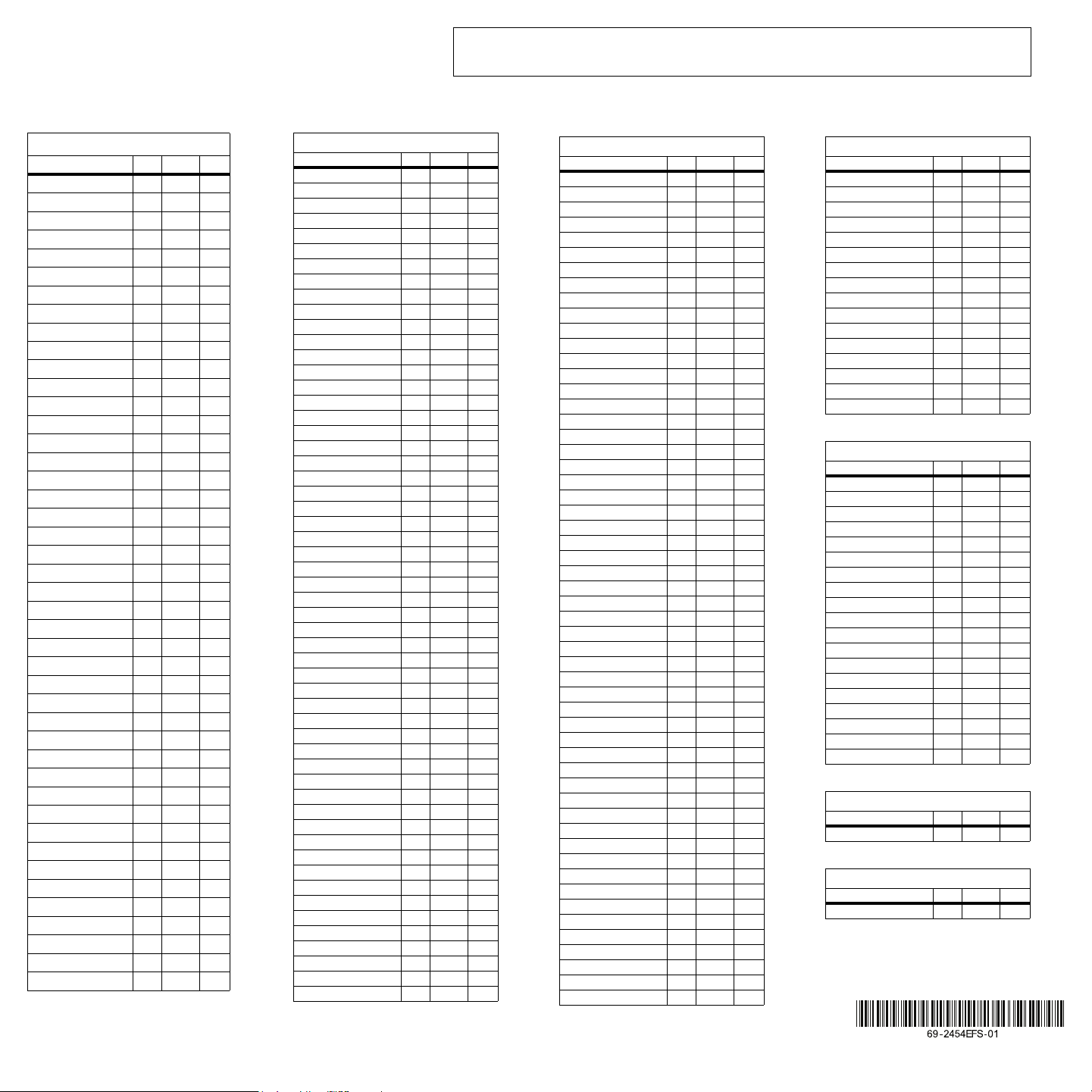
City / Ville Lat. Long. Adj.
ABBOTSFORD 49 -122 0
BANFF 51 -115 1
BARRIE 44 -80 0
BURNABY 49 -122 0
CALGARY 51 -114 1
CAPE BRETON 46 -60 0
CHICOUTIMI 48 -71 0
DAWSON 64 -139 1
EASTMAIN 52 -78 0
EDMONTON 53 -113 1
FORT SEVERN 56 -87 1
HALIFAX 44 -63 0
HAMILTON 49 -112 0
IQALUIT 63 -68 0
INUKJUAK 58 -78 0
KELOWNA 50 -119 0
KITCHENER 43 -80 0
LONDON 42 -81 0
MISTASSINI 50 -73 0
MONTREAL 45 -73 0
NIAGARA 43 -79 0
OSHAWA 43 -78 0
OTTAWA - GATINEAU 45 -75 0
QUEBEC 46 -71 0
REGINA 50 -104 1
RICHMOND 49 -123 0
ROUYN-NORANDA 48 -79 0
SASKATOON 52 -106 1
SEPT-ILES 50 -66 -1
SHERBROOKE 45 -71 0
ST. ANTHONY 51 -55 0
ST CATHARINES 43 -79 0
SAINT JOHN (NB) 45 -66 0
ST. JOHN'S (NFLD) 47 -52 0
SUDBURY 46 -81 0
THUNDER BAY 48 -89 1
TORONTO 43 -79 0
TROIS-RIVIÈRES 46 -72 0
VANCOUVER 49 -123 0
VICTORIA 49 -123 0
WHITEHORSE 60 -135 1
WINDSOR 42 -83 1
WINNIPEG 49 -97 0
YELLOWKNIFE 62 -114 1
USA
City Lat. Long. Adj.
ABILENE 32 -99 1
ALBUQUERQUE 35 -106 0
ALLENTOWN 40 -75 0
AMARILLO 35 -101 1
ANCHORAGE 61 -149 1
ATLANTA 33 -84 1
AUSTIN 30 -97 0
BAKERSFIELD 35 -119 0
BALTIMORE 39 -76 0
BATON ROUGE 30 -91 0
BEAUMONT 30 -94 0
BILLINGS 45 -108 0
BIRMINGHAM 33 -86 0
BOISE 43 -116 1
BOISE CITY 36 -102 1
BOSTON 42 -71 0
BROWNSVILLE 25 -97 0
BUFFALO 42 -78 0
CEDAR RAPIDS 41 -91 0
CHARLOTTE 35 -80 0
CHATTANOOGA 35 -85 1
CHEYENNE 41 -104 0
CHICAGO 41 -87 0
CINCINNATI 39 -84 1
CLEVELAND 41 -81 0
COLOMBUS 39 -82 0
COLORADO SPRINGS 38 -104 0
CORPUS CHRISTI 27 -97 0
DALLAS 32 -96 0
DENVER 39 -104 0
DES MOINES 41 -93 0
DETROIT 42 -83 1
DULUTH 46 -92 0
EL PASO 31 -106 0
ERIE 42 -80 0
EUGENE 44 -123 0
EVANSVILLE 37 -87 0
FLINT 43 -83 1
FORT LAUDERDALE 26 -80 0
FORT WAYNE 41 -85 1
FRESNO 36 -119 0
GRAND RAPIDS 42 -85 1
GREAT FALLS 47 -111 0
GREENSBORO 36 -79 0
HAMPTON 37 -76 0
HARTFORD 41 -72 0
HONOLULU 21 -157 0
HOUSTON 29 -95 0
HUNTSVILLE 34 -86 0
INDIANAPOLIS 39 -86 1
JACKSON 32 -90 0
JACKSONVILLE 30 -81 0
KANSAS CITY 39 -94 0
KNOXVILLE 35 -83 1
LAKEWOOD 39 -105 0
USA
City Lat. Long. Adj.
LANSING 42 -84 1
LAREDO 27 -99 1
LAS VEGAS 36 -115 0
LEXINGTON 38 -84 1
LINCOLN 40 -96 0
LITTLE ROCK 34 -92 0
LONG BEACH 33 -118 0
LOS ANGELES 34 -118 0
LOUISVILLE 38 -85 1
LUBBOCK 33 -101 1
MACON 32 -83 1
MADISON 43 -89 0
MEMPHIS 35 -90 0
MIAMI 25 -80 0
MILWAUKEE 43 -87 0
MINNEAPOLIS 44 -93 0
MOBILE 30 -88 0
MODESTO 37 -120 0
MONTGOMERY 32 -86 0
NASHVILLE 36 -86 0
NEW ORLEANS 29 -90 0
NEW YORK 40 -74 0
NORFOLK 36 -76 0
OKLAHOMA CITY 35 -97 0
OMAHA 41 -95 0
ORLANDO 28 -81 0
OVERLAND PARK 38 -94 0
OXNARD 34 -119 0
PEORIA 40 -89 0
PHILADELPHIA 40 -75 0
PHOENIX 33 -112 0
PITTSBURG 40 -79 0
PLANO 33 -96 0
PORTLAND 45 -122 0
PROVIDENCE 41 -71 0
RALEIGH 35 -78 0
RAPID CITY 44 -103 1
RENO 39 -119 0
RICHMOND 37 -77 0
ROANOKE 37 -79 0
ROCHESTER 43 -77 0
ROCKFORD 42 -89 0
SACRAMENTO 38 -121 0
SALT LAKE CITY 40 -111 0
SAN ANTONIO 29 -98 1
SAN DIEGO 32 -117 0
SAN FRANCISCO 37 -122 0
SANTA ROSA 38 -122 0
SAVANNAH 32 -81 0
SEATTLE 47 -122 0
SHREVEPORT 32 -93 0
SOUTH BEND 41 -86 0
SPOKANE 47 -117 0
SPRINGFIELD (IL) 39 -89 0
SPRINGFIELD (MA) 42 -72 0
USA
City Lat. Long. Adj.
SPRINGFIELD (MO) 37 -93 0
ST. LOUIS 38 -90 0
SYRACUSE 43 -76 0
TALLAHASSEE 30 -84 1
TAMPA 27 -82 0
TOLEDO 41 -83 1
TOPEKA 39 -95 0
TUCSON 32 -110 0
TULSA 36 -95 0
VIRGINIA BEACH 36 -75 0
WACO 31 -97 0
WASHINGTON DC 38 -77 0
WICHITA 37 -97 0
WINSTON-SALEM 36 -80 0
YONKERS 40 -73 0
YOUNGSTOWN 41 -80 0
MÉXICO
Ciudad Lat. Long. Adj.
TIJUANA 32 -117 0
NOGALES 31 -111 0
CIUDAD JUAREZ 31 -106 0
MATAMOROS 26 -97 0
NUEVO LAREDO 27 -99 1
MONTERREY 25 -100 1
CHIHUAHUA 28 -106 0
MAZATLÁN 23 -106 0
TAMPICO 22 -98 1
ZACATECAS 22 -102 1
LÉON 21 -101 1
LA PAZ 24 -110 0
MEXICO CITY 19 -99 1
PUEBLA 19 -98 1
GUADALAJARA 20 -103 1
OAXACA 17 -96 0
ACAPULCO 16 -100 1
CANCUN 21 -86 0
MERIDA 21 -89 0
PUERTO RICO
Ciudad Lat. Long. Adj.
SAN JUAN 18 -66 0
REPÚBLICA DOMINICANA
Ciudad Lat. Long. Adj.
SANTO DOMINGO 18 -70 1
Longitude/Latitude/Correction factor
Longitude/Latitude/Facteur de correction
Longitud/Latitud/Factor de corrección
If your city is not listed below, use a nearby city or refer to the website “www.geonames.org”.
Si votre ville n’est pas dans la liste, utiliser une ville avoisinante ou consulter le site web «www.geonames.org».
Si su ciudad no figura en la lista, buscar una ciudad vecina o consultar el sitio web “www.geonames.org”.
69-2454EFS-01_400-070-004-A (TI070_RPLS540A) USA.book Page 8 Tuesday, May 18, 2010 10:55 AM