Loading ...

TECHNICAL DESCRIPTION
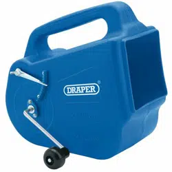
IDENTIFICATION
Drive handle.
Carry handle.
Texture/pattern control
adjuster.
Pressure bar.
Roller.
TITLE PAGE
INTRODUCTION:
USER MANUAL FOR: Tyrolean Flicker Machine
Stock No: 02171
Part No: PTF
As our user manuals are continually updated, users should make sure that they
use the very latest version.
Downloads are available from: http://drapertools.com/manuals
Draper Tools Limited
Hursley Road
Chandler’s Ford
Eastleigh
Hampshire
SO53 1YF
UK
Website: drapertools.com
Product Helpline: +44 (0) 23 8049 4344
General Fax: +44 (0) 23 8026 0784
UNDERSTANDING THIS MANUALS SAFETY CONTENT:
WARNING! – Information that draws attention to the risk of injury or death.
CAUTION! – Information that draws attention to the risk of damage to the
product or surroundings.
COPYRIGHT © NOTICE:
Copyright © Draper Tools Limited.
Permission is granted to reproduce this publication for personal and educational
use only. Commercial copying, redistribution, hiring or lending is prohibited.
No part of this publication may be stored in a retrieval system or transmitted in
any other form or means without written permission from Draper Tools Limited.
In all cases this copyright notice must remain intact.
REVISIONS:
Date first published March 2018.
GUARANTEE
GUARANTEE
Draper tools have been carefully tested and inspected before shipment and are guaranteed to be
free from defective materials and workmanship.
Should the tool develop a fault, please return the complete tool to your nearest distributor or
contact:
Draper Tools Limited, Chandler’s Ford, Eastleigh, Hampshire, SO53 1YF. England.
Telephone Sales Desk: (023) 8049 4333 or:
Product Helpline (023) 8049 4344.
A proof of purchase must be provided.
If upon inspection it is found that the fault occurring is due to defective materials or workmanship,
repairs will be carried out free of charge. This guarantee period covering parts/labour is 6 months
from the date of purchase except where tools are hired out when the guarantee period is 90 days
from the date of purchase. The guarantee is extended to 24 months for parts only. This guarantee
does not apply to normal wear and tear, nor does it cover any damage caused by misuse, careless
or unsafe handling, alterations, accidents, or repairs attempted or made by any personnel other
than the authorised Draper warranty repair agent.
Note: If the tool is found not to be within the terms of warranty, repairs and carriage charges will be
quoted and made accordingly.
This guarantee applies in lieu of any other guarantee expressed or implied and variations of its
terms are not authorised.
Your Draper guarantee is not effective unless you can produce upon request a dated receipt or
invoice to verify your proof of purchase within the guarantee period.
Please note that this guarantee is an additional benefit and does not affect your statutory rights.
Draper Tools Limited.
- 3 -- 2 - - 4 -
ASSEMBLY AND OPERATION
FIG.2
FIG.4
FIG.1
INSTALLING THE ROLLER AND DRIVE
HANDLE – FIGS.1 – 4
Note: The flicker machine can be set up for the
drive handle to be used in right or left-handed
operation.
Place the roller
inside the housing of the
machine.
– The drive slots
of the roller must be
aligned with the bush support holes.
Once aligned, the drive handle
can be fed
through the bush support and then on through
the entire length of the roller until the drive lug
on the handle locating bush
engages with
the drive slots in the roller.
– The locating bush must be pushed fully
through the bush support until its drive lug
engages in the drive slot at the other end of
the roller.
– Rotate the roller, as necessary to align.
Slide the washer down over the protruding
end of the handle and secure with the wing
nut.
INSTALLING THE PRESSURE BAR
– The pressure bar
is installed inside the
machine housing.
– The threaded end of the bar is located through
the hole on the same side of the housing that
features the notched guide of the texture/pattern
control adjuster
.
– Align the other end of the bar with the opposite
hole and use the washer and cross slot screw to
secure the bar in place.
FIG.3
A
B
C
A
B
C
Loading ...
Loading ...
Loading ...