Loading ...
Loading ...
Loading ...
ENGLISH
CUSTOMER RESPONSIBILITIES
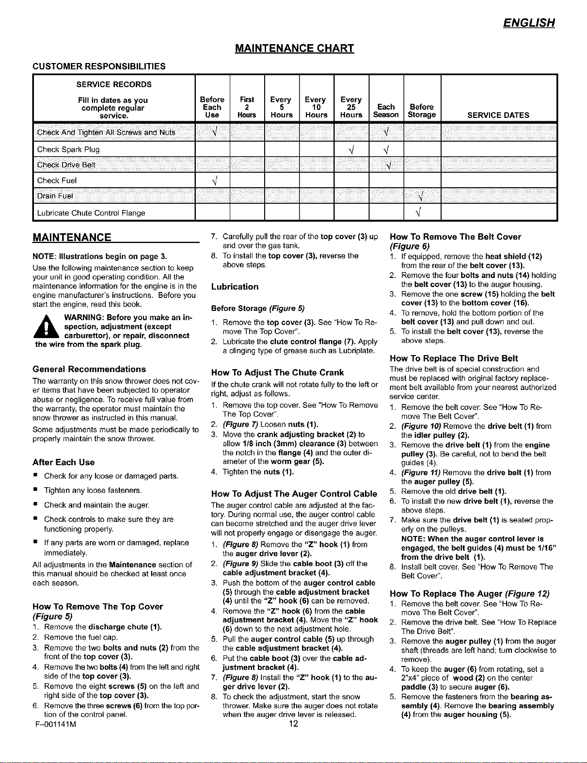
MAINTENANCE CHART
SERVICE RECORDS
Fill in dates as you Before First Every Every Every
complete regular Each 2 5 10 25 Each Before
service. Use Hours Hours Hours Hours Season Storage SERVICE DATES
Check Spark Plug
Check Fuel
Lubricate Chute Control Flange
MAINTENANCE
NOTE: Illustrations begin on page 3.
Use the following maintenance section to keep
your unit in good operating condition. All the
maintenance information for the engine is in the
engine manufacturer's instructions. Before you
start the engine, read this book.
_k ARNING: Before you make an in-
spection, adjustment (except
carburettor), or repair, disconnect
the wire from the spark plug.
General Recommendations
The warranty on this snow thrower does not cov-
er items that have been subjected to operator
abuse or negligence. To receive full value from
the warranty, the operator must maintain the
snow thrower as instructed in this manual
Some adjustments must be made periodically to
properly maintain the snow thrower.
After Each Use
• Check for any loose or damaged parts,
• Tighten any loose fasteners.
• Check and maintain the auger.
• Check controls to make sure they are
functioning properly.
• If any parts are worn or damaged, replace
immediately,
All adjustments in the Maintenance section of
this manual should be checked at least once
each season.
How To Remove The Top Cover
(Figure 5)
1. Remove the discharge chute (1).
2. Remove the fuel cap,
3. Remove the two bolts and nuts (2) from the
front of the top cover (3).
4. Remove the two belts (4) from the left and right
side of the top cover (3).
5. Remove the eight screws (5) on the left and
right side of the top cover (3).
6. Remove the three screws (6) from the top por-
tion of the control panel.
F_01141M
7. Carefully pull the rear of the top cover (3) up
and over the gas tank.
8, To install the top cover (3), reverse the
above steps.
Lubrication
Before Storage (Figure 5)
1. Remove the top cover (3). See "How To Re-
move The Top Cover",
2, Lubricate the clute control flange (7). Apply
a clinging type of grease such as Lubrip[ate.
How To Adjust The Chute Crank
If the chute crank will not rotate fully to the left or
right, adjust as foUows.
1. Remove the top cover. See "How To Remove
The Top Cover".
2, (Figure 7) Loosen nuts (1).
3. Move the crank adjusting bracket (2) to
allow 1/8 inch (3mm) clearance (3) between
the notch in the flange (4) and the outer di-
ameter of the worm gear (5).
4. Tighten the nuts (1).
How To Adjust The Auger Control Cable
The auger control cable are adjusted at the fac-
tory. During normal use. the auger control cable
can become stretched and the auger drive lever
will not properly engage or disengage the auger.
1. (Figure 8) Remove the "Z" hook (1) from
the auger drive lever (2).
2, (Figure 9) Slide the cable boot (3) off the
cable adjustment bracket (4).
3. Push the bottom of the auger control cable
(5) through the cable adjustment bracket
(4) until the "Z" hook (6) can be removed,
4. Remove the "Z" hook (6) from the cable
adjustment bracket (4). Move the "Z" hook
(6) down to the next adjustment hole.
5. Pull the auger control cable (5) up through
the cable adjustment bracket (4).
6. Put the cable boot (3) over the cable ad-
justment bracket (4).
7. (Figure 8) Install the "Z" hook (1) to the au-
ger drive lever (2).
8, To check the adjustment, start the snow
thrower. Make sure the auger does not rotate
when the auger drive lever is released.
12
How To Remove The Belt Cover
(Figure 6)
1, If equipped, remove the heat shield (12)
from the rear of the belt cover (13).
2, Remove the four bolts and nuts (14) holding
the belt cover (13) to the auger housing,
3, Remove the one screw (15) holding the belt
cover (13) to the bottom cover (16).
4, To remove, hold the bottom portion of the
belt cover (13) and pull down and out,
5, To install the belt cover (13), reverse the
above steps.
How To Replace The Drive Belt
The drive belt is of special construction and
must be replaced with original factory replace-
ment belt available from your nearest authorized
service center.
1, Remove the belt cover. See "How To Re-
move The Belt Cover",
2, (Figure 10) Remove the drive belt (1) from
the idler pulley (2).
3, Remove the drive belt (1) from the engine
pulley (3). Be careful, not to bend the belt
guides (4),
4, (Figure 11) Remove the drive belt (1) from
the auger pulley (5).
5, Remove the old drive belt (1).
6, To install the new drive belt (1). reverse the
above steps.
7, Make sure the drive belt (1) is seated prop-
erly on the pulleys,
NOTE: When the auger control lever is
engaged, the belt guides (4) must be 1/16"
from the drive belt (1).
8, Install belt cover. See "How To Remove The
Belt Cover".
How To Replace The Auger (Figure 12)
1, Remove the belt cover. See "How To Re-
move The Belt Cover",
2, Remove the drive belt, See "How To Replace
The Drive Belt",
3, Remove the auger pulley (1) from the auger
shaft (threads are left hand; turn clockwise to
remove).
4. To keep the auger (6) from rotating, set a
2"x4" piece of wood (2) on the center
paddle (3) to secure auger (6).
5. Remove the fasteners from the bearing as-
sembly (4). Remove the bearing assembly
(4) from the auger housing (5).
Loading ...
Loading ...
Loading ...