Loading ...
Loading ...
Loading ...
SLIM DUCT TECHNICAL OVERVIEW
F-3
ENGLISH
Components
Accessory Louver Motors (not shown)
Separate motors located in the accessory supply air louver
control the operation of the motorized louvers. The louver
motors are stepper type motors that move the louvers up/
down. The motors are controlled by pulsed voltage that cannot
be measured. If the louver does not move when it should, check
for a bind in the louvers.
All of the louver motors are controlled via commands received
from the remote control.
8
6
7
Piping Temperature Sensor
The Piping Temperature Sensor senses indoor coil temperature in the cooling mode and in the heating mode. This sensor is
used for Anti Freezing and Anti Cold Blow cycles. The sensor also provides critical temperature information to the ECU that
may be used in frequency adjustments.
Condensate Pump
The Slim Duct unit has a built in condensate pump. The pump is connected to the circuit board. The pump is energized
whenever the Float Switch indicates that water needs to be pumped from the cassette. The oat switch connects onto the
circuit board.
The oat switch and pump are located behind the removable insulated cover next to the electrical control box. The pump
is hermetically sealed and requires no maintenance. The oat switch is a normally closed switch, that opens as water rises.
The oat switch requires no maintenance.
Gravity Drain Ports
The indoor unit has the option for either gravity drain systems or the use of an internal condensate pump with oat switch.
The pump is capable of minimal lift. If high lift is required, the water from the Slim Duct unit should be pumped to a eld
supplied condensate pump that is capable of high lift.
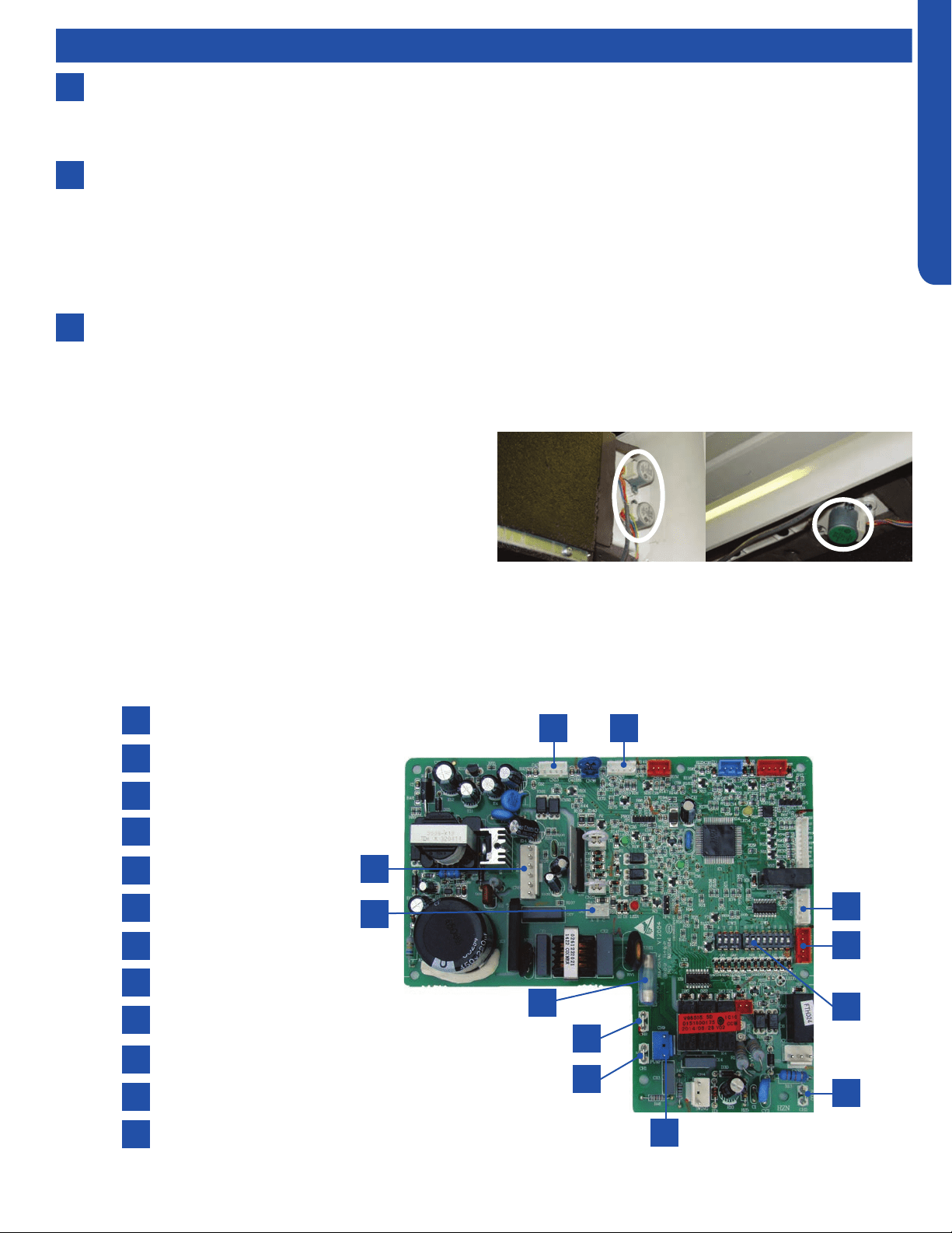
Indoor Unit Circuit Board
The indoor unit circuit board controls the switching functions of the indoor unit. All control decisions are made by the outdoor
unit ECU. The indoor board has some limited diagnostic capability which will be covered in this manual.
1
4
7
10
2
5
8
11
3
6
9
12
L Terminal
N Terminal
Communication Terminal
5A 250V Fuse
CN13 Sensors
CN18 Float Switch
CN1 Wired Remote
DIP Switches
CN14 Stepper Motor
CN15 Stepper Motor
CN6 Fan Motor
CN9 Condensate Pump
1
4
7
10
2
5
8
11
3
6
9
12
Loading ...
Loading ...
Loading ...