Loading ...
Loading ...
Loading ...
NOTE:Some maintenance procedures may require
special tools or skills. If you are unsure about
these procedures take your unit to an authorized
service dealer.
MAINTENANCE SCHEDULE
These required maintenance procedures should be
performed at the frequency stated in the table. They
should also be included as part of any seasonal tune-up.
I_ WARNING: To prevent serious personal I
injury, never do maintenance or repairs with I
unit running. Always do maintenance and I
repairs on a cool unit. Disconnect spark plug
wire to ensure the unit will not start.
FREQUENCY MAINTENANCE REQUIRED REFER TO:
Before Starting Engine Fill fuel tank with correct off and fue! mixture. Page 9
Every 10 Hours Clean and re-oil air filter, Page 18
Every 50 Hours Check spark plug condition and gap. Page 20
LINE INSTALLATION FOR THE SPEEDSPOOL ®
Always use genuine Ryobi 0,080 in, (2.03 ram)
replacement line. Larger line may make the engine
overheat or fail.
WARNING: Never use metal-reinforced line,
wire, chain, or rope, etc. These can break off
and become a dangerous projectile.
3.
4.
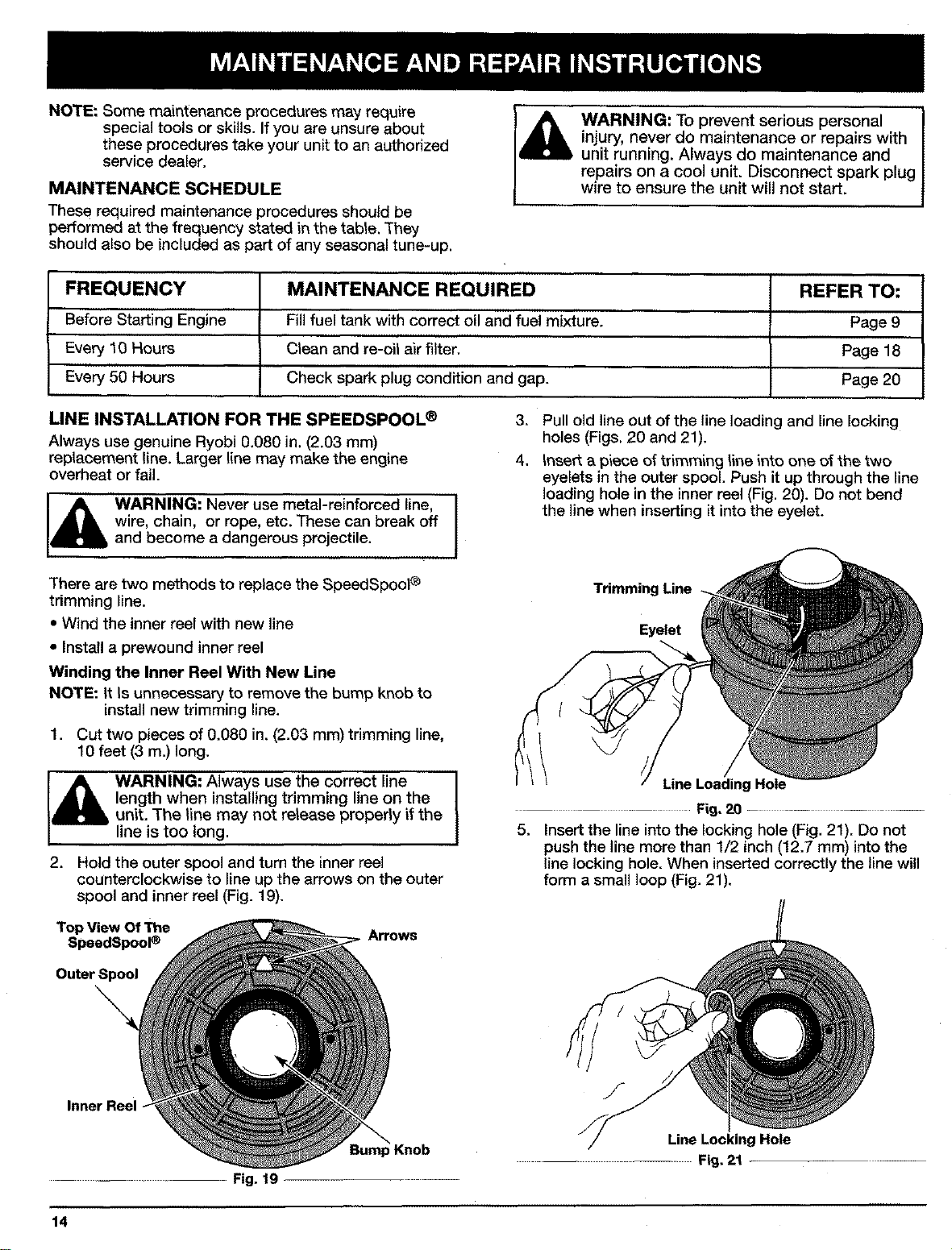
Pull old lineout of the line loading and line locking
holes (Figs. 20 and 21).
Insert a piece of trimming line into one of the two
eyelets in the outer spool. Push it up through the line
loading hole in the inner reel (Fig. 20). Do not bend
the line when inserting it into the eyelet.
There are two methods to replace the SpeedSpool ®
trimming line.
• Wind the inner reel with new line
• Install a prewound inner reel
Winding the Inner Reel With New Line
NOTE: It Is unnecessary to remove the bump knob to
install new trimming line.
1. Cut two pieces of 0.080 in. (2.03 mm) trimming line,
10 feet (3 m.) long,
WARNING: Always use the correct line
length when installing trimming line on the
unit. The line may not release propedy if the
line is too long.
2. Hold the outer spool and turn the inner reel
counterclockwise to line up the arrows on the outer
spool and inner reel (Fig. 19).
Trimming Line
Eyelet
Line Loading Hole
Fig,20 ..........
5. Insert the line into the locking hole (Fig. 21), Do not
push the line more than 1/2 inch (12.7 mm) into the
line locking hole. When inserted correctly the line will
form a small loop (Fig. 21),
Top View Of The
SpeedSpool ® Arrows
Ou_rSpool
Inner Reel
.... Fig. 19
)Knob
/
Line LockingHole
...... Fig. 21
14
Loading ...
Loading ...
Loading ...