Loading ...
Loading ...
Loading ...
SERVICE
C. With finger pressure press seat firmly and squarely into cav-
ity. See Figure IOA. Polished face of seat faces inside of pump.
If seat will not locate properly, pLAce cardboard washer over
polished face and use piece of 3/4" standard pipe for press-
ing purposes. See Figure'10B.
FIGURE lOB
4830194
D. Dispose of cardboard washer and clean surface of seat.
E. Clean motor shaft.
F. Reassemble back half of pump to motor.
G. Apply detergent solution to inside diameter of rotating seal
member.
H. Slide rotating member on shaft until rubber drive ring hits
shaft shoulder. NOTICE: BE SURE you do not chip or scratch
seal face on shaft shoulder or seal will leak!
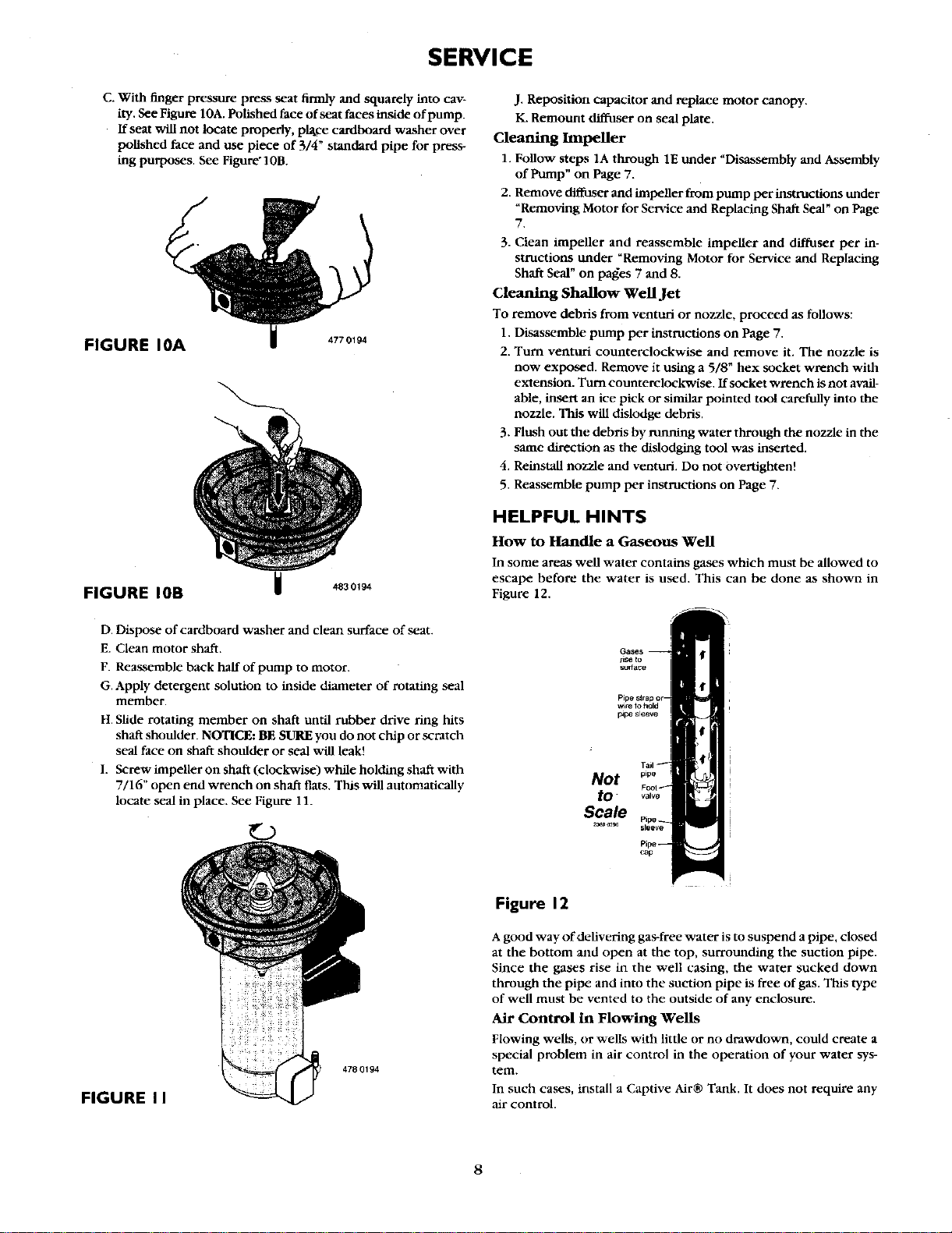
I. Screw impeller on shaft (clockwise) while holding shaft with
7/16" open end wrench on shaft flats. This will automatically
locate seal in place. See Figure 11.
J. Reposition capacitor and replace motor canopy.
K. Remount diffuser on seal plate.
Cleaning Inlpeller
1. Follow steps 1A through 1E tinder "Disassembly and Assembly
of Pump" on Page 7.
2. Remove diffuser and impeller from pump per instructions tinder
"Removing Motor for Service and Replacing Shaft Seal" on Page
7.
3. Clean impeller and reassemble impeller and diffuser per in-
stnictions under "Removing Motor for Service and Replacing
Shaft Seal" on pages 7 and 8.
Cleaning Shallow Well Jet
To remove debtis from venturi or nozzle, proceed as follows:
1. Disassemble pump per instructions on Page 7.
2. Turn venturi counterclockwise and remove it. The nozzle is
now exposed. Remove it using a 5/8" hex socket wrench with
extension. Turn counterclockwise. If socket wrench is not avail-
able, insert an ice pick or similar pointed tool carefully into the
nozzle. This will dislodge debris.
3. Flush out the debris by running water through the nozzle in the
same direction as the dislodging tool was inserted.
4. Reinstall nozzle and venturi. Do not overtighten!
5. Reassembh- _ pump per instructions on Page 7.
HELPFUL HINTS
How to Handle a Gaseous Well
In some areas well water contains gases which must be allowed to
escape before the water is used. This can be done as shown in
Figure 12.
_seto
sudace
Not
tO- valve
Scale
FIGURE I I
478 0194
Figure 12
A good way of.delivering gas-free water is to suspend a pipe, closed
at the bottom :and open at the top, surrounding the suction pipe.
Since the gases rise in the well casing, the water sucked down
through the pipe and into the suction pipe is free of gas. This type
of well must be vented to the outside of any enclosure.
Air Control in Flowing Wells
Flowing wells, or wells with little or no drawdown, could create a
special problem in air control in the operation of your water sys-
tem.
In such cases, install a Captive Air® Tank. It does not require any
air control.
8
Loading ...
Loading ...
Loading ...