Save This Manual
For Future Reference
owners
manual
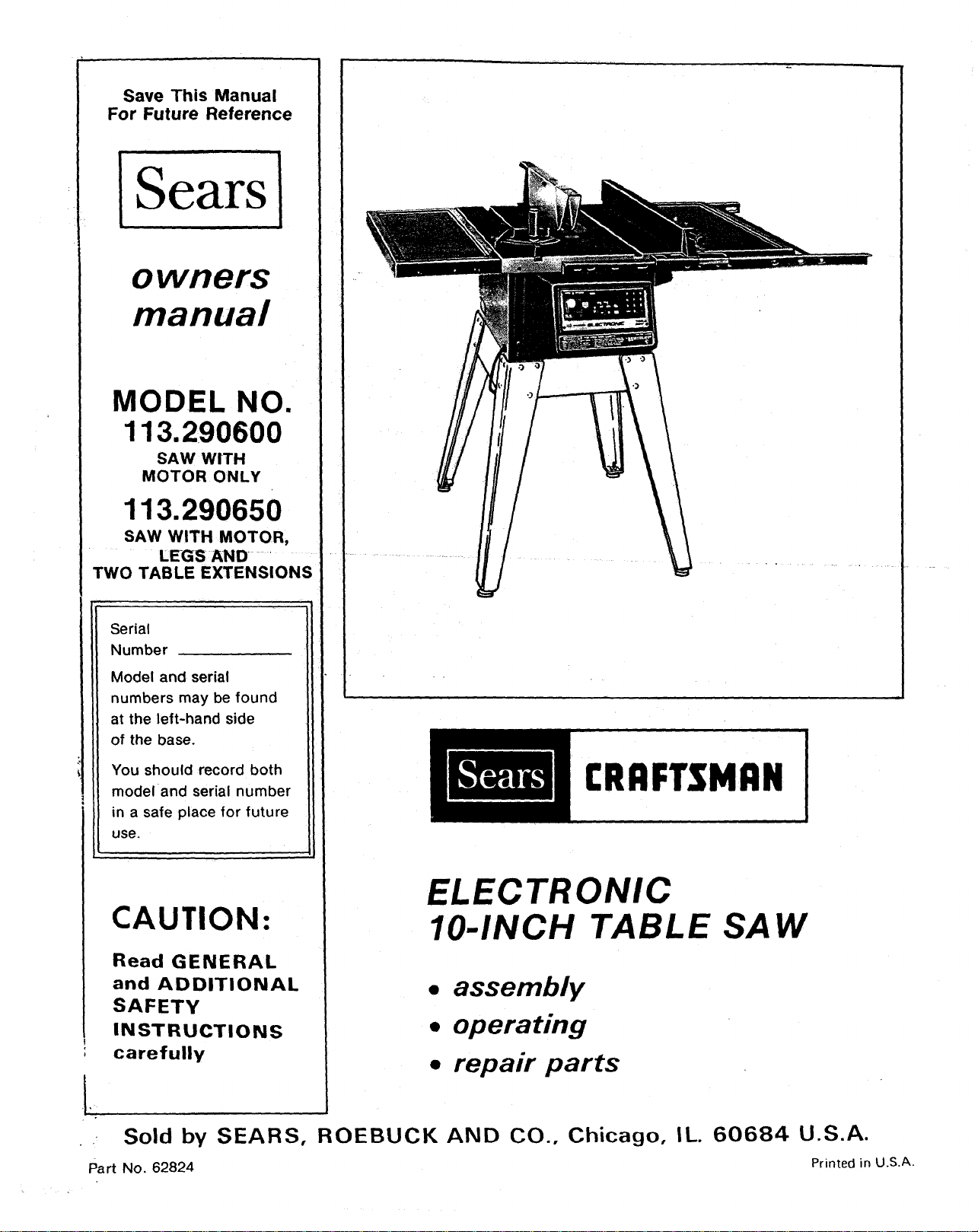
MODEL NO.
113.290600
SAW WITH
MOTOR ONLY
113.290650
SAW WITH MOTOR,
LEGS AND
TWO TABLE EXTENSIONS
Serial
Number
Model and serial
numbers may be found
at the left-hand side
of the base.
You should record both
model and serial number
in a safe place for future
use.
CAUTION:
!
Read GENERAL
and ADDITIONAL
SAFETY
INSTRUCTIONS
carefully
CRRFTSMRN
ELECTRONIC
IO-INCH TABLE SAW
• assembly
• operating
• repair parts
• Sold by SEARS, ROEBUCK AND CO., Chicago, IL.
Part No. 62824
60684 U.S.A.
Printed in U.S.A.

FULL ONE YEAR WARRANTY ON CRAFTSMAN TABLE SAW
If within one _year from the date of purchase, this Craftsman Table Saw fails due to a detect in material or
workmanship, Sears will repair It, free of charge.
WARRANTY SERVICE IS AVAILABLE BY SIMPLY CONTACTING THE NEAREST SEARS SERVICE
CENTER/DEPARTMENT THROUGHOUT THE UNITED STATES.
This warranty applies only while this product Is used In the United States.
This warranty gives you specific legal rights, and you may also have other fights which vary from state to state.
SEARS, ROEBUCK AND CO., DEPT. 698/731A Sears Tower, Chicago, IL 60684
GENERAL SAFETY INSTRUCTIONS FOR POWER TOOLS
1. KNOW YOUR POWER TOOL
Read and understand the owner's manual and
labels affixed to the tool. Learn its application
and limi.tations as well as the specific potential
hazards peculiar to this tool.
2. GROUND ALL TOOLS
This tool is equipped with an approved
3-conductor cord and a 3-prong grounding
type plug to fit the proper grounding type
receptacle. The green conductor in the cord is
the grounding wire. Never connect the green
wire to a live terminal.
3. KEEP GUARDS IN PLACE,
in working order, and in proper adjustment and
alignment.
4. REMOVE ADJUSTING KEYS
AND WRENCHES
Form habit of checking to see that keys and
adjusting wrenches are removed from tool
before turning it on.
5. KEEP WORK AREA CLEAN
Cluttered areas and benches invite accidents.
Floor must not be slippery due to wax or
sawdust.
6. AVOID DANGEROUS ENVIRONMENT
Don't use power tools in damp or wet locations
or expose them to rain. Keep work area well
bighted. Provide adequate surrounding work
space.
7. KEEP CHILDREN AWAY
All visitors should be kept a safe distance from
work area.
8, MAKE WORKSHOP KID-PROOF
with padlocks, master switches, or by
removing starter keys.
9. DON'T FORCE TOOL
It will do the job better and safer at the rate for
which it was designed.
10. USE RIGHT TOOL
Don't force too_ or attachment to do a job it was
not designed for.
11. WEAR PROPER APPAREL
Do not wear loose clothing, gloves, neckties or
jewelry (rings, wrist watches) to get caught in
moving parts. Nonslip footwear is
recommended. Wear protective hair covering to
contain long hair. Roll long sleeves above the
elbow.
12. USE SAFETY GOGGLES (Head Protection)
Wear Safety goggles (must comply with ANSI
Z87.1) at all times. Everyday eyeglasses only
have impact resistant lenses, they are NOT
safety glasses. Also, use face or dust mask if
cutting operation is dusty, and ear protectors
(plugs or muffs) during extended periods of
operation.
13. SECURE WORK
Use clamps or a vise to hold work when
practical. It's safer than using your hand, frees
both hands to operate tool.
14. DON'T OVERREACH
Keep proper footing and balance at all times,
15. MAINTAIN TOOLS WITH CARE
Keep tools sharp and clean for best and safest
performances. Follow instructions for
lubricating and changing accessories.
16. DISCONNECT TOOLS
before servicing; when changing accessories
such as blades, bits, cutters, etc.
17. AVOID ACCIDENTAL STARTING
Make sure switch is in "OFF" position before
plugging in.
18. USE RECOMMENDED ACCESSORIES
Consult the owner's manual for recommended
accessories. Follow the instructions that
accompany the accessories. The use of
improper accessories may cause hazards.
19. NEVER STAND ON TOOL
Serious inj ury could occur if the tool is tipped or
if the cutting tool is accidentally contacted.
Do not store materials above or near the tool
such that it is necessary to stand on the tool to
reach the m.
20. CHECK DAMAGED PARTS
Before further use of the tool, a guard or other
part that is damaged should be carefully
checked to ensure that it will operate properly
and perform its intended function. Check for
alignment of moving parts, binding of moving
parts, breakage of parts, mounting, and any
other conditions that may effect its operation. A
guard or other part that is damaged should be
properly repaired or replaced.
21. DIRECTION OF FEED
Feed work into a blade or cutter against the
direction of rotation of the blade or cutter only.
22. NEVER LEAVE TOOL RUNNING
UNATTENDED
Turn power off. Don't leave tool until it comes to
a complete stop.
ADDITIONAL SAFETY INSTRUCTIONS FOR TABLE SA lr3!
WARNING: FOR YOUR OWN SAFETY, DO NOT B. Wear safety goggles that comply with ANSI
OPERATE YOUR SAW UNTIL IT IS COMPLETELY Z87.1, and a face shield or dust mask if
ASSEMBLED AND INSTALLED ACCORDING TO
THE INSTRUCTIONS... AND UNTIL YOU HAVE
READ AND UNDERSTAND THE FOLLOWING:
1. GENERAL SAFETY INSTRUCTIONS FOR
POWER TOOLS... SEE PAGE 2
2. GETTING TO KNOWYOUR SAW... SEE PAGE
22
3. BASIC SAW OPERATION ..... SEE PAGE 27
4. MAINTENANCE ............. : SEE PAGE 41
5, STABILITY OF SAW
If there is any tendency for the saw to tip over or
move during certain cutting operations such as
cutting extremely large heavy panels or long
heavy boards, the saw should be bolted down.
If you attach any kind of table extensions over
24" wide to either end of the saw, make sure you
either bolt the saw to the bench or floor as
appropriate, or support the outer end of the
extension from the bench or floor, as
appropriate.
6. L_)CATION
The saw should be positioned so neither the
operator nor a casual observer isforced to stand
in line with the saw blade.
7. KICKBACKS
A "KICKBACK" occurs during a rip-type
operation when a part or all of the workpiece is
thrown back violently toward the operator.
Keep your face and body to one side of the
sawblade, out of line with a possible "Kickback."
Kickbacks -- and possible injury from them
can usually be avoided by:
A. Maintaining the rip fence parallel to the
sawblade.
B. Keeping the sawblade sharp. Replace or
sharpen antikickback pawls when points
become dull.
C. Keeping sawblade guard, spreader, and
antikickback, pawls in place and operating
properly. The spreader must be in alignment
with the sawblade and the pawls must stop a
kickback once it has started. Check their
action before ripping.
D. NOT ripping work that is twisted or warped or
does not have a straight edge to guide along
the rip fence.
E. NOT releasing work until you have pushed it
all the way past the sawblade.
F. Using a push stick for ripping widths of 2to 6
in., and an auxiliary fence and push block for
ripping widths narrower than 2 in. (See "Basic
Saw Operation Using The Rip Fence"
section.)
G. NOT confining the cut-off piece when
ripping or cross-cutting.
8. PROTECTION: EYES, HANDS, FACE, EARS,
BODY
A. If any part of your saw is missing,
malfunctioning, or has been damaged or
broken such as the motor switch,
electronic' controls, or other operating
control, a safety device or the power cord...
cease operating immediately until the
particular part is properly repaired or
replaced.
operation is dusty. Wear ear .plugs or muffs
during extended :peldods of operation
C. Small loose pieces of wood or other objects
that contact the rear of the revolving blade
can be thrown back at_"_he'0_rator at
excessive speed. This can usually be avoided
by keeping the guard and spreader in place
for all thru-sawing operations-(sawing
entirely thru the work) AND by removing all
loose pieces from the table w tb a_!ong Stick of
wood IMMEDIATELY' after they are cut off.
D. Use extra caution when the guard assembly is
removed for resawing_ da,doing, rabbeting, or
molding -- replace the guard as soon as that
operation is completed. '-'--
E. For rip or rip-type cutso the .following endof a
workpiece to which a push stick or push
board s applied mu-st, jbe ° squar_e
(perpendicular to the ferlce) in order that feted
pressure applied to ,the workp_ece.by"the
push stick or block does not cause 'the
workpiece to come away from. thefence, and
possibly cause a kickback.
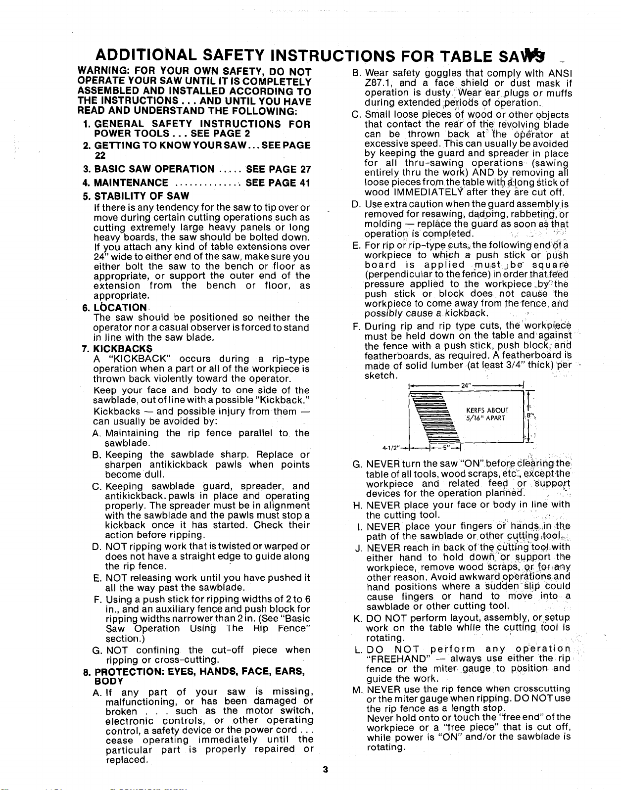
F. During rip and rip type cuts, the workpi.ece
must be held down on the table andagainst
the fence with a push stick, push block, and
featherboards, as required. A featherbOard is
made of solid lumber (at least 3/4" thick) per
sketch.
I" 24" ",1
5/_" APART
G. NEVER turn the saw "ON"before c[e_rin_g the
table of all tools, wood scraps, etc_.,except,the
workpiece and related feed or Support
devices for the operation plan'*ned.
H. NEVER place your face or body in ine with
the cutting tool.
I. NEVER place your fingers or hand&,in .the
path of the sawblade or other Cqt.ting4oo:L.
J. NEVER reach in back of the cdtti.'ng"tool.with
either hand to hold dowr_i or S!Jp.portthe
workpiece, remove wood scraps,.er for,any
other reason. Avoid awkward 0perat.i0rnsand
hand positions where a Suddenslip could
cause fingers or hand to move into a
sawblade or other cutting tool.
K. DO NOT perform layout, assembly, or setup
work on the table while the cutting tool is
rotating.
L. DO NOT perform any operation
"FREEHAND" -- always use either the rip
fence or the miter gauge to pOsition and
guide the work.
M. NEVER use the rip fence when crosscutting
or the miter gauge when ripping. DO NOT use
the rip fence as a length stop.
Never hold onto or touch the "free end" of the
workpiece or a "free piece" that is cut off,
while power is "ON" and/or the sawblade _s
rotating.
3
N_$_ "OFF" the saw and disconnect the
_p6wer cord when removing the table insert,
changing the cutting tool, removing or
replacing the blade guard, or making
adjustments.
O. Provide adequate support to the rear and
sides of the saw table for wider or long
workpieces.
P. Plastic and composition (like hardboard)
materials may be cut on your saw. However,
s nce these are usually quite hard and
slippery, the antikickback pawls may not stop
a kickback.
Therefore, be especially attentive to
following proper set-up and cutting
procedures for ripping. Do not stand, or
permit anyone else to stand, in line with a
potential kickback.
Q. If you stall or jam the sawblade in the
workpiece turn saw "OFF" and remove the
workpiece from the sawblade. Check to see if
the sawblade is parallel to the miter gauge
grooves and if the spreader is in proper
alignment with the sawblade. If ripping atthe
time, check to see if the rip fence is parallel
with the sawblade. Readjust as indicated.
R. DO NOT remove smafi pieces of cut-off
material that may become trapped inside the
blade guard while the saw is running. This
could endanger your hands or cause a
kickback. Turn saw "OFF" and wait until
blade stops.
S. Use extra care when ripping wood that has a
twisted grain or is twisted or bowed -- it may
rock on the table and/or pinch the sawblade.
9. KNOW YOUR CUTTING TOOLS
A. Dull, gummy, or improperly sharpened or set
cutting tools can cause material to stick, jam,
stall the saw, or kickback at the operator.
Minimize potential injury by proper cutting
tool and machine maintenance
NEVER ATTEMPT TO FREE A STALLED
SAWBLADE WITHOUT FIRST TURNING
THE SAW OFF.
B Never use grinding wheels abrasive cut-off
wheels, friction wheels (metal slitting blades)
w_re wheels or buffing wheels.
10. USE ONLY ACCESSORIES DESIGNED FOR
THIS SAW
11. Crosscutting operations are worked more
conveniently and with greater safety if an
auxiliary wood facing is attached to the miter
gauge using the holes provided. However, the
facing must not interfere with the proper
functioning of the sawblaae guard.
12. Make sure the top of the arbor or cutting tool
rotates toward you whon _tanding in normal
operating position. Also make sure the cutting
tool, arbor collars and arbor nut are installed
properly. Keep the cutting tool as low as
possible for the operation being performed.
Keep all guards in place whenever possible.
13. Do not use any blade or other cutting tool
marked for an operating speed less than 3450
RPM. Never use a cutting tool larger in diameter
than the diameter for which the saw was
designed. For greatest safety and efficiency
when ripping, use the maximum diameter blade
for which the saw is designed, since under these
conditions the spreader is nearest the blade.
14. Adjust table inserts flush with the table top.
NEVER operate the saw unless the proper insert
is installed.
15. NEVER feed material into the cutting tool from
the rear of the saw. An accident and serious
injury could result.
16. THINK SAFETY.
Safety is a combination of operator common
sense and alertness at all times when the saw is
being used.
17. NEVER use another person as a substitute for a
table extension, or as additional support for a
workpiece that is longer or wider than the basic
saw table, or to assist in feeding or supporting or
pulling the workpiece.
DO NOT pull the workpiece through the
sawblade - position your body at the nose (in-
feed) side of the guard: start and complete the
cut from that same side. This will require added
table support for long or wide workpieces that
extend beyond the length or width of the saw
table.
18. NOTE AND FOLLOW SAFETY INSTRUC-
TIONS THAT APPEAR ON THE FRONT OF
YOUR SAW.
('_ _ FOR YOUR OWN SAFETY: ...............
1.READANOUNDERSTANDOWNER'S_A_AL s. NEV_ REACHA_OU_OOROVERSAW_-AC_
BEF_e _TING _;_Ne. 7. NeVeR PERFORMANy_ERATION"FReEHANO" _ e_l_ is c_lEe
2. _AR SAFETYGC_ES PElf ANSIZS_,. 8. USESAWB_OE _ARD F_ "ntnU-S_l_"
3. KESRHANDSOUTOFPATHOFSAWBLAD_9. SHUTO_FMAST_ SWI_CHANOALLOW
4. KNOWHOWTOAV_O"KICKSACKS". SAWBLADETOSTO_eeeOREAO_JSnNG
• use "PUSH STICK" WHEN REOUIRED O_ SERVICINg.
19. WARNING: DO NOT ALLOW FAMILIARITY
(GAINED FROM FREQUENT USE OF YOUR
SAW) TO BECOME COMMONPLACE.
ALWAYS REMEMBER THAT A CARELESS
FRACTION OF A SECOND IS SUFFICIENT TO
INFLICT SEVERE INJURY.
20. WARNING: THE 2-1/2" SAW PULLEYAND THE
2-1/2" MOTOR PULLEY FURNISHED, WILL
RUN THE BLADE AT APPROXIMATELY 3450
RPM WHEN USED WITH A 3450 RPM MOTOR.
NEVER SUBSTITUTE THESE PULLEYS TO
INCREASE THIS SPEED BECAUSE IT COULD
BE DANGEROUS.
NOTE: Do not overtighten arbor nut. Use the arbor
wrench to }ust "snug" it.
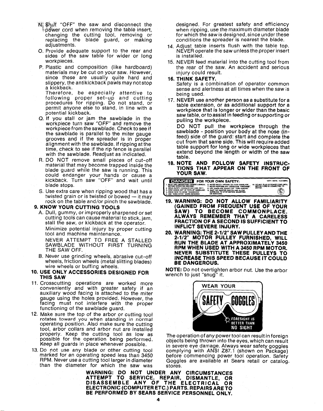
WEAR YOUR
The operation of any power tool can result in foreign
objects being thrown into the eyes, which can result
in severe eye damage. Always wear safety goggles
complying with ANSI Z87.1 (shown on Package)
before commencing power tool operation. Safety
Goggles are available at Sears retail or catalog.
stores.
WARNING: DO NOT UNDER ANY CIRCUMSTANCES
ATTEMPT TO SERVICE, REPAIR, DISMANTLE, OR
DISASSEMBLE ANY OF THE ELECTRICAL OR
ELECTRONIC (COMPUTER ETC.) PARTS. REPAIRS ARE TO
BE PERFORMED BY SEARS SERVICE PERSONNEL ONLY.
4
MOTOR SPECIFICATIONS AND ELECTRICAL REQUIREMENTS
This saw isdesigned'to use a 3450 RPM motor only.
Do not use any motor that runs faster than 3450
RPM. It is wired for operation on 110-120volts, 60
Hz., alternating current. IT MUST NOT BE
CONVERTED TO OPERATE ON 230 VOLTS.
CONNECTING TO POWER SOURCE OUTLET
This saw must be grounded while in use to protect
the operator from electrical shock.
If power cord is worn or cut, or damaged in anyway,
have it replaced immediately.
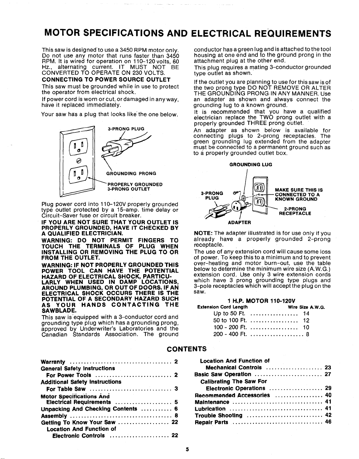
Your saw has a plug that looks likethe one below.
3-PRONG PLUG
....... GROUNDING PRONG
PROPERLY GROUNDED
3-PRONG OUTLET
Plug power cord into 110-120V properly grounded
type outlet protected by a 15-amp. time delay or
Circuit-Saver fuse or circuit breaker.
IF YOU ARE NOT SURE THAT YOUR OUTLET IS
PROPERLY GROUNDED, HAVE IT CHECKED BY
A QUALIFIED ELECTRICIAN.
WARNING: DO NOT PERMIT FINGERS TO
TOUCH THE TERMINALS OF PLUG WHEN
INSTALLING OR REMOVING THE PLUG TO OR
FROM THE OUTLET.
WARNING: IF NOT PROPERLY GROUNDED THIS
POWER TOOL CAN HAVE THE POTENTIAL
HAZARD OF ELECTRICAL SHOCK, PARTICU-
LARLY WHEN USED IN DAMP LOCATIONS,
AROUND PLUMBING, OR OUT OF DOORS. IF AN
ELECTRICAL SHOCK OCCURS THERE IS THE
POTENTIAL OF A SECONDARY HAZARD SUCH
AS YOUR HANDS CONTACTING THE
SAWBLADE.
This saw is_equipped with a 3-conductor cord and
grounding type plug which has a grounding prong,
approved by Underwriter's Laboratories and the
Canadian Standards Association. The ground
conductor has a green lug and is attached to the tool
housing at one end and to the ground prong in the
attachment plug at the other end.
This plug requires a mating 3-conductor grounded
type outlet as shown.
If the outlet you are planning to use for this saw is of
the two prong type DO NOT REMOVE OR ALTER
THE GROUNDING PRONG.IN ANY MANNER. Use
an adapter as shown and always connect the
grounding lug to a known ground.
It is recommended that you have a qualified
electrician replace the TWO prong outlet with a
properly grounded THREE prong outlet.
An adapter as shown below is available for
connecting plugs to 2-prong receptacles. The
green grounding lug extended from the adapter
must be connected to a permanent ground such as
to a properly grounded outlet box.
GROUNDING LUG
MAKE SURE THIS IS
3-PRONG _'_ .3TED TO A
PLUG KNOWN GROUND
\
2-PRONG
RECEPTACLE
ADAPTER
NOTE: The adapter illustrated is for use only if you
already have a properly grounded 2-prong
receptacle.
The use of any extension cord will cause some loss
of power: To keep this to a minimum and to prevent
over-heating and motor burn-out, use the table
below to determine the minimum wire size (A.W.G.)
extension cord. Use only 3 wire extension cords
which have 3 prong grounding type plugs and
3-pole receptacles which will accept the plug on the
saw.
1 H.P. MOTOR 110-120V
Extension Cord Length Wire Size A.W.G.
Up to 50 Ft.................. 14
50 to 100 Ft.................. 12
100 - 200 Ft.................. 10
200 - 400 Ft.................... 8
CONTENTS
Warranty .................................... 2
General Safety Instructions
For Power Tools ........................... 2
Additional Safety Instructions
For Table Saw ............................. 3
Motor Specifications And
Electrical Requirements .................... 5
Unpacking And Checking Contents ........... 6
Assembly .................................... 8
Getting To Know Your Saw .................. 22
Location And Function of
Electronic Controls ..................... 22
Location And Function of
Mechanical Controls .................... 23
Basic Saw Operation ........................ 27
Calibrating The Saw For
Electronic Operations ................... 29
Recommended Accessories ................. 40
Maintenance ................................ 41
Lubrication ................................. 41
Trouble Shooting ........................... 42
Repair Parts ................................ 46
UNPACKING AND CHECKING CONTENTS
TOOLS NEEDED
.. Medium Screwdriver
(_ Hammer Small Screwdriver
#2 Phillips Type
Pliers _'- Screwdriver
@
Wrenches
1/2 in, 9/16 in.
Combination Square 3/4 in.
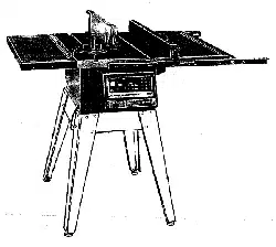
Model 113.290600 Table Saw is shipped complete in
one carton with motor but DOES NOT INCLUDE
Table Extensions or Steel Legs.
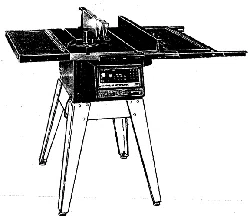
Model 113.290650 Table Saw is shipped complete in
one carton and INCLUDES Motor, Two Table
Extensions and Steel Legs.
Separate all parts from packing materials and check
each one with the illustration and the list of Loose
Parts to make certain all items are accounted for
before discarding any packing material.
If any parts are missing, do not attempt to assemble
the table saw, plug in the power cord or turn the
switch on until the missing parts are obtained and
are installed correctly.
Remove the protective oil that is applied to the table
top and edges of the table. Use any ordinary
household type grease and spot remover.
CAUTION: Never use gasoline, naptha or similar
highly volatile solvents.
Apply a coat of automobile wax to the table.
Wipe all parts thoroughly with a clean, dry cloth.
WARNING: FOR YOUR OWN SAFETY, NEVER
CONNECT PLUG TO POWER SOURCE OUTLET
UNTIL ALL ASSEMBLY STEPS ARE COMPLETE,
AND YOU READ AND UNDERSTAND THE
SAFETY AND OPERATIONAL INSTRUCTIONS.
P Q
T
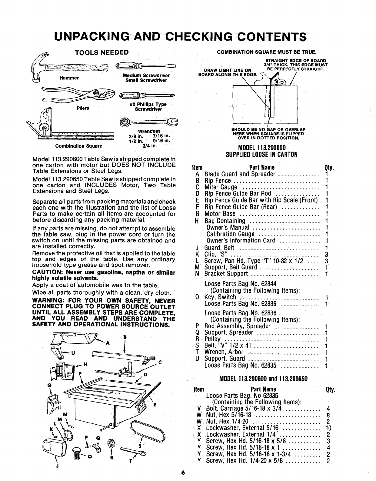
COMBINATION SQUARE MUST BE TRUE.
STRAIGHT EDGE OF BOARD
3/4" THICK. THIS EDGE MUST
CRAW LIGHT LINE ON BE PERFECTLY STRAIGHT.
BOARO ALONG THIS EDGE. _'\
SHOULD BE NO GAP OR OVERLAP
HERE WHEN SQUARE IS FLIPPED
OVER IN DOTTED POSITION.
MODEL113.290600
SUPPLIEDLOOSEIN CARTON
Item Part Name Qty.
A Blade Guard and Spreader .............. 1
B Rip Fence ............................. 1
C Miter Gauge .......................... 1
D Rip Fence Guide Bar Rod ............... 1
E Rip Fence GuideBar with Rip Scale (Front) 1
F Rip Fence Guide Bar (Rear) ............. 1
G Motor Base ........................... 1
H Bag Containing ........................ 1
Owner's Manual ....................... 1
Calibration Gauge ...................... 1
Owner's Information Card .............. 1
J Guard, Belt ........................... 1
K Clip, "S" .............................. 3
L Screw, Pan Hd. Type "T" 10-32 x 1/2 .... 3
M Support, Belt Guard .................... 1
N Bracket Support ........................ 1
Loose Parts Bag No. 62844
(Containing the Following Items):
0 Key, Switch ........................... 1
Loose Parts Bag No. 62836 ............. 1
Loose Parts Bag No. 62836
(Containing the Following Items):
P Rod Assembly, Spreader ............... 1
Q Support, Spreader ..................... 1
R Pulley ................................ 1
S Belt, "V" 1/2 x 41 ...................... 1
T Wrench, Arbor ........................ 1
U Support, Guard ........................ 1
Loose Parts Bag No. 62835 ............. 1
MODEL113.290600and!13.290650
Item PartName Qty.
LooseParts Bag.No62835
(Containingthe Following Items):
V Bolt,Carriage5/16-18 x 3/4 ............ 4
W Nut,Hex 5/16-18 ...................... 8
W Nut, Hex1/4-20 ....................... 2
X Lockwasher,External5/16 ............. 10
X Lockwasher,External1/4. ............. 2
Y Screw, HexHd 5/16-18 x 5/8 ........... 3
Y Screw, HexHd. 5/16-18 x 1 ............. 4
Y Screw, HexHd. 5/16-18 x 1-3/4 ......... 2
Y Screw, HexHd. 1/4-20 x 5/8 ............ 2
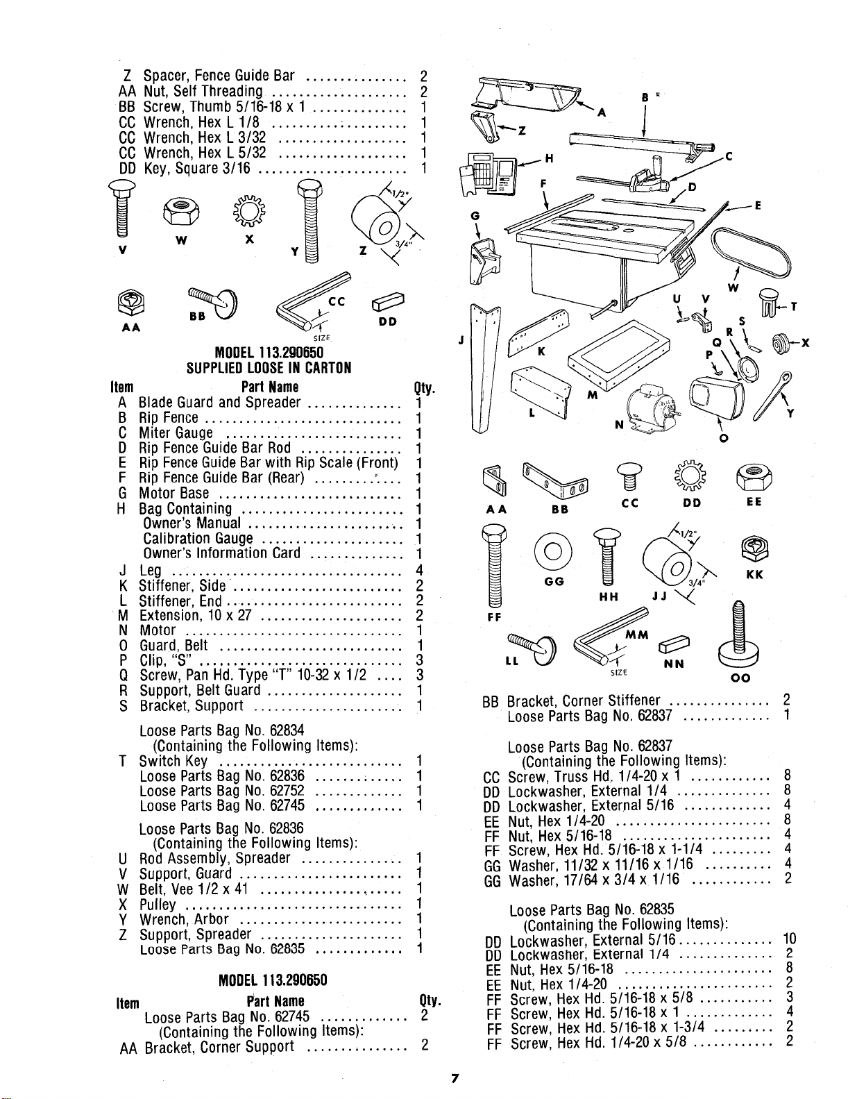
Z Spacer, Fence Guide Bar ............... 2
AA Nut, Self Threading .................... 2
BB Screw, Thumb 5/16-18 x 1 .............. 1
CC Wrench, Hex L 1/8 .......... . ......... 1
CC Wrench, Hex L 3/32 ................... 1
CC Wrench, Hex L 5/32 ................... 1
DD Key, Square 3/16 ............ . ......... 1
w
v
@
AA
y_ /_i/2,_:.x/x
X
z ,,_ ,
DD
SIZE
MODEL113.290650
SUPPLIEDLOOSEIN CARTON
Part Name
Item Qty.
A Blade Guard and Spreader .............. 1
B Rip Fence ............................. 1
C Miter Gauge .......................... 1
D Rip Fence Guide Bar Rod ............... 1
E Rip Fence Guide Bar with Rip Scale (Front) 1
F Rip Fence Guide Bar (Rear) ......... :... 1
G Motor Base ........................... 1
H Bag Containing ........................ 1
Owner's Manual ........................ 1
Calibration Gauge ..................... 1
Owner's Information Card .............. 1
J Leg .................................. 4
K Stiffener, Side. ........................ 2
L Stiffener, End ........................... 2
M Extension, 10 x 27 ..................... 2
N Motor ................................ 1
0 Guard, Belt ........................... 1
P Clip,"S". ............................. 3
Q Screw, Pan Hd. Type "1" 10-32 x 1/2 .... 3
R Support, Belt Guard .................... 1
S Bracket, Support ...................... 1
Loose Parts Bag No. 62834
(Containing the Following Items):
T Switch Key ........................... 1
Loose Parts Bag No. 62836 ....... . ..... 1
Loose Parts Bag No. 62752 ............. 1
Loose Parts Bag No. 62745 ............. 1
Loose Parts Bag No. 62836
(Containing the Following Items):
U Rod Assembly, Spreader ............... 1
_/ Support, Guard ........................ 1
W Belt, Vee 1/2 x 41 ..................... 1
X Pulley ................................ 1
Y Wrench, Arbor ........................ 1
Z Support, Spreader ..................... 1
Loo_e Parts Bag No. 62835 ............. 1
MODEL113.290650
Item Part Name Qty.
Loose Parts Bag No. 62745 ............. 2
(Containing the Following Items):
AA Bracket, Corner Support ............... 2
G
AA BB CC DD EE
BB Bracket, Corner Stiffener ............... 2
Loose Parts Bag No. 62837 ............. 1
Loose Parts Bag No. 62837
(Containing the Following Items):
CC Screw, Truss Hd, 1/4-20 x 1 ............ 8
DD Lockwasher, External 1/4 .............. 8
DD Lockwasher, External 5/16 ............. 4
EE Nut, Hex 1/4-20 ....................... 8
FF Nut, Hex 5/16-18 ...................... 4
FF Screw, Hex Hd: 5/16-18 x 1-1/4 ......... 4
GG Washer, 11/32 x 11/16 x 1/16 .......... 4
GG Washer, 17/64 x 3/4 x 1/16 ............ 2
Loose Parts Bag No. 62835
(Containing the Following Items):
DD Lockwasher, External 5/16 ............... 10
DD LOckwasher, External 1/4 .............. 2
EE Nut, Hex 5/16-18 ...................... 8
EE Nut, Hex 1/4-20 ....................... 2
FF Screw, Hex Hd. 5/16-18 x 5/8 ........... 3
FF Screw, Hex Hd. 5/16-18 x 1 ............. 4
FF Screw, Hex Hd. 5/16-18 x 1-3/4 ......... 2
FF Screw, Hex Hd. 1/4-20 x 5/8 ............ 2
7
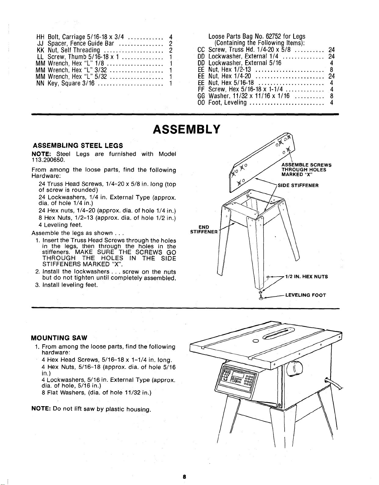
HH B01t, Carriage 5/16-18 x 3/4 ............ 4
JJ Spacer, Fence Guide Bar ............... 2
KK Nut, Self Threading .................... 2
LL Screw, Thumb 5/16-18 x 1 .............. 1
MM Wrench, Hex "L" 1/8 ................... 1
MM Wrench, Hex "L" 3/32 .................. 1
MM Wrench, Hex "L" 5/32 .................. 1
NN Key, Square 3/16 ...................... 1
Loose Parts Bag No. 62752 for Legs
(Containing the Following Items):
CC Screw, Truss Hd. 1/4-20 x5/8 .......... 24
DD Lockwasher, External 1/4 .............. 24
DD Lockwasher, External 5/16 4
EE Nut, Hex 1/2-13 ....................... 8
EE Nut, Hex 1/4-20 ....................... 24
EE Nut, Hex 5/16-18 ...................... 4
FF Screw, Hex 5/16-18 x 1-1/4 ............. 4
GG Washer, 11/32 x 11/16 x 1/16 .......... 8
00 Foot, Leveling ......................... 4
ASSEMBLY
ASSEMBLING STEEL LEGS
NOTE: Steel Legs are furnished with Model
113.290650.
From among the loose parts, find the following
Hardware:
24 Truss Head Screws, 1/4-20 x 5/8 in. long (top
of screw is rounded)
24 Lockwashers, 1/4 in. External Type (approx.
dia. of hole 1/4 in.)
24 Hex nuts, 1/4-20 (approx. dia. of hole 1/4 in.)
8 Hex Nuts, 1/2-13 (approx. dia. of hole 1/2 in.)
4 Leveling feet.
Assemble the legs as shown...
1. Insert the Truss Head Screws through the holes
in the legs, then through the holes in the
stiffeners. MAKE SURE THE SCREWS GO
THROUGH THE HOLES rN THE SIDE
STIFFENERS MARKED "X".
2. Install the Iockwashers... screw on the nuts
but do not tighten until completely assembled.
3. Install leveling feet.
END
STIFFENER'
/
ASSEMBLE SCREWS
THROUGH HOLES
MARKED "X"
_SIDE STIFFENER
. 1/2 IN. HEX NUTS
MOUNTING SAW
1. From among the loose parts, find the following
hardware:
4 Hex Head Screws, 5/16-18 x 1-1/4 in, long.
4 Hex Nuts 5/16-18 (approx. dia. of hole 5/16
in.)
4 Lockwashers, 5/16 in. External Type (approx.
dia. of hole, 5/16 in.)
8 Flat Washers, (dia. of hole 11/32 in.)
NOTE: Do not lift saw by plastic housing.
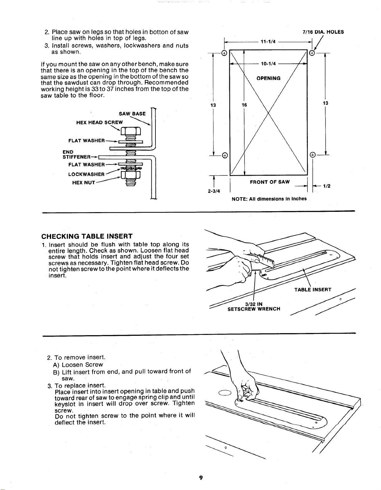
2.Placesawonlegssothatholesin bottonofsaw
lineupwithholesintopof legs.
3.Installscrews,washers,Iockwashersandnuts
asshown.
Ifyoumountthesawonanyotherbench,makesure
thatthereisanopeninginthetopofthebenchthe
samesizeastheopeninginthebottomofthesawso
thatthesawdustcandropthrough.Recommended
workingheightis33to37inchesfromthetopofthe
sawtabletothefloor.
' SAW BASE ]'_
HEXHEAOSCREW i
FLATWASHER7 , ,
END
STIFFENER--_I i
FLAT WASH ER -'-'-__
LOCKWASHER ....._w_
HEX
r
-- ---_)
13
2-3/4
11-1/4
10-1/4 --
7/16 DIA. HOLES
16
13
FRONT OF SAW
NOTE: All dimensions in inches
CHECKING TABLE INSERT
1. Insert should be flush with table top along its
entire length. Check as shown, Loosen flat head
screw that holds insert and adjust the four set
screws as necessary. Tighten flat head screw. Do
not tighten screw to the point where it deflects the
insert.
3/32 IN
i SETSCREW WRENCH
2. To remove insert.
A) Loosen Screw
B) Lift insert from end, and pull toward front of
saw.
3. To replace insert,
Place insert into insert opening in table and push
toward rear of saw to engage spring clipand until
keyslot in insert will drop over screw. Tighten
screw.
Do not tighten screw to the point where it will
deflect the insert.
9
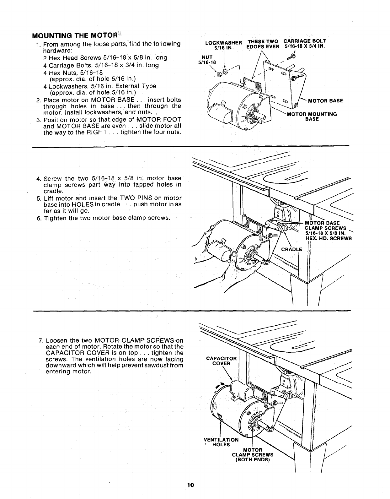
MOUNTING THE MOTOR:
1. From among the Ioo,se parts,"find the following
hardware:
2 Hex Head Screws 5/16-18 x 5/8 in. long
4 Carriage Bolts, 5/16-18 x 3/4 in. long
4 Hex Nuts, 5/16-18
(approx. dia. of hole 5/16 in.)
4 Lockwashers, 5/16 in_ External Type
(approx. dia. of hole 5/16 in.)
2. Place motor on MOTOR BASE .... insert bolts
through holes in base.., then through the
motor. Install Iockwashers, and nuts.
3. Position motor so that edge of MOTOR FOOT
and MOTOR BASE are even ... slide motor all
the way to the RIGHT... tighten the four nuts.
LOCKWASHER THESE TWO CARRIAGE BOLT
6/16 IN. EDGES EVEN 5/16-18 X 3/4 IN.
5/16-18
__ _ MOTOR BASE
MOT% sOUNT'NG
4. Screw the two 5/16-18 x 5/8 in. motor base
clamp screws part Way into tapped holes in
cradle.
5. Lift motor and insert the TWO PINS on motor
base into HOLES in cradle.., push motor in as
far as it will go.
6. Tighten the two motor base clamp screws.
CLAMP SCREWS
5/16-18 X 5/8 IN. "_"
HEX. HD. SCREWS
7. Loosen the two MOTOR CLAMP SCREWS on
each end of motor. Rotate the motor so that the
CAPACITOR COVER is on top.., tightenthe
screws. The ventilation holes are now facing
downward which will help prevent sawdust from
entering motor.
CAPACITOR
COVER
\
VENTILATION
HOLES
MOTOR
CLAMP SCREWS
(BOTH ENDS)
10
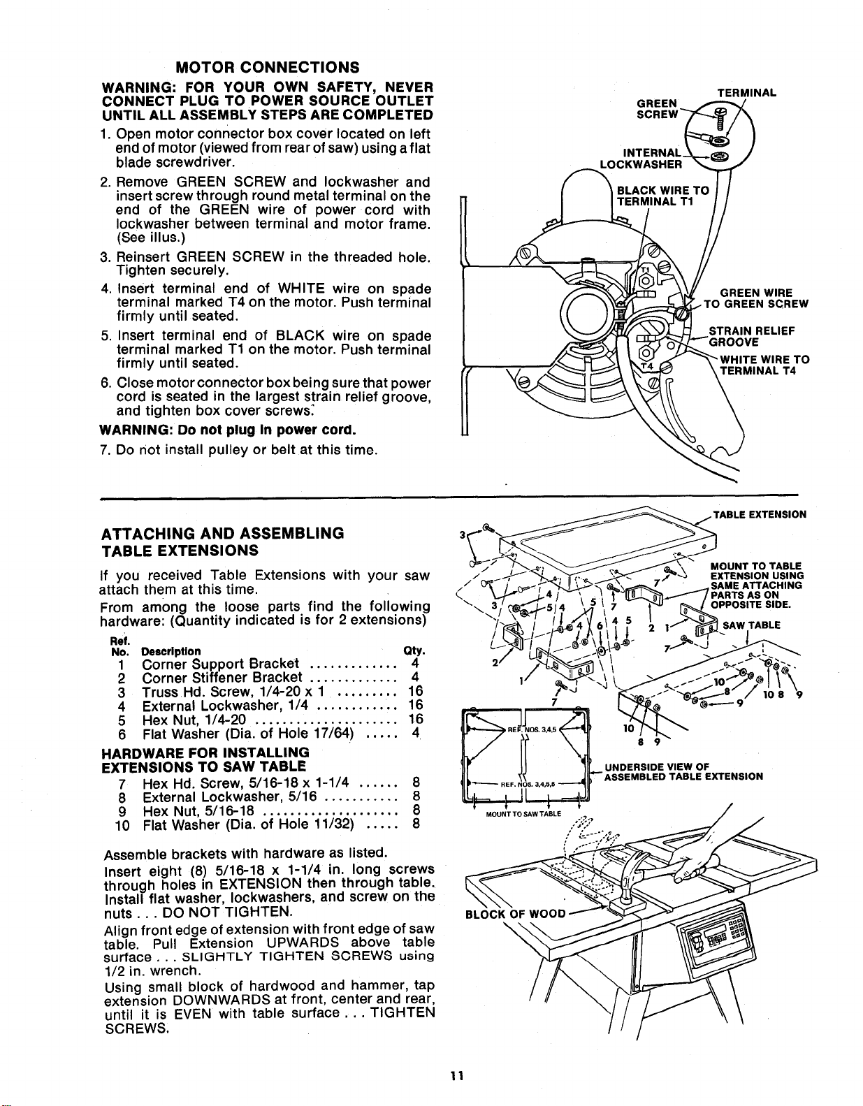
MOTOR CONNECTIONS
WARNING: FOR YOUR OWN SAFETY, NEVER
CONNECT PLUG TO POWER SOURCE OUTLET
UNTIL ALL ASSEMBLY STEPS ARE COMPLETED
1. Open motor connector box cover located on left
end of motor (viewed from rear of saw) using a flat
blade screwdriver.
2. Remove GREEN SCREW and Iockwasher and
insert screw through round metal terminal on the
end of the GREEN wire of power cord with
Iockwasher between terminal and motor frame.
(See illus.)
3. Reinsert GREEN SCREW in the threaded hole.
Tighten securely.
4. Insert terminal end of WHITE wire on spade
terminal marked T4 on the motor. Push terminal
firmly until seated.
5. Insert terminal end of BLACK wire on spade
terminal marked T1 on the motor. Push terminal
firmly until seated.
6. Close motor connector box being sure that power
cord is seated in the largest strain relief groove,
and tighten box cover screws:
WARNING: Do not plug In power cord.
7. Do not install pulley or belt at this time.
L¢
GREEN
INTERNAL
TERMINAL
GREEN WIRE
.TO GREEN SCREW
STRAIN RELIEF
)VE
ITE WIRE TO
TERMINAL T4
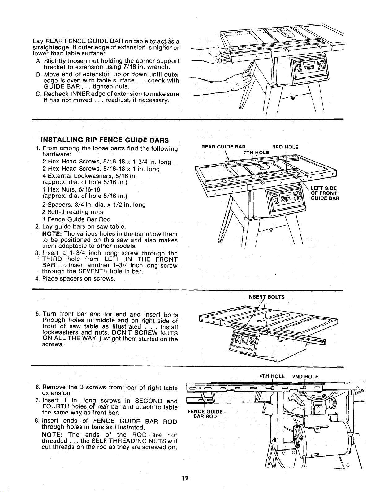
ATTACHING AND ASSEMBLING
TABLE EXTENSIONS
If you received Table Extensions with your saw
attach them at this time.
From among the loose parts find the following
hardware: (Quantity indicated is for 2 extensions)
Ref.
No. Description Qty.
1 Corner Support Bracket ............. 4
2 Corner Stiffener Bracket 4
3 Truss Hd. Screw, 1/4-20 x 1 ......... 16
4 External Lockwasher, 1/4 ............ 16
5 Hex Nut, 1/4-20 ..................... 16
6 Flat Washer (Dia. of Hole 17/64) ..... 4
HARDWARE FOR INSTALLING
EXTENSIONS TO SAW TABLE
7 Hex Hd. Screw, 5/16-18 x 1-1/4 ...... 8
8 External Lockwasher, 5/16 ........... 8
9 Hex Nut, 5/16-18 .................... 8
10 Flat Washer (Dia. of Hole 11/32) ..... 8
Assemble brackets with hardware as listed.
Insert eight (8) 5/16-18 x 1-1/4 in. long screws
through holes in EXTENSION then through table.
Install flat washer, Iockwashers, and screw on the
nuts... DO NOT TIGHTEN.
Align front edge of extension with front edge of saw
table. Pull Extension UPWARDS above table
surface... SLIGHTLY TIGHTEN 8CREW8 using
1/2 in. wrench.
Using small block of hardwood and hammer, tap
extension DOWNWARDS at front, center and rear,
until it is EVEN with table surface... TIGHTEN
SCREWS,
BLOCK OF WOO n
\
11
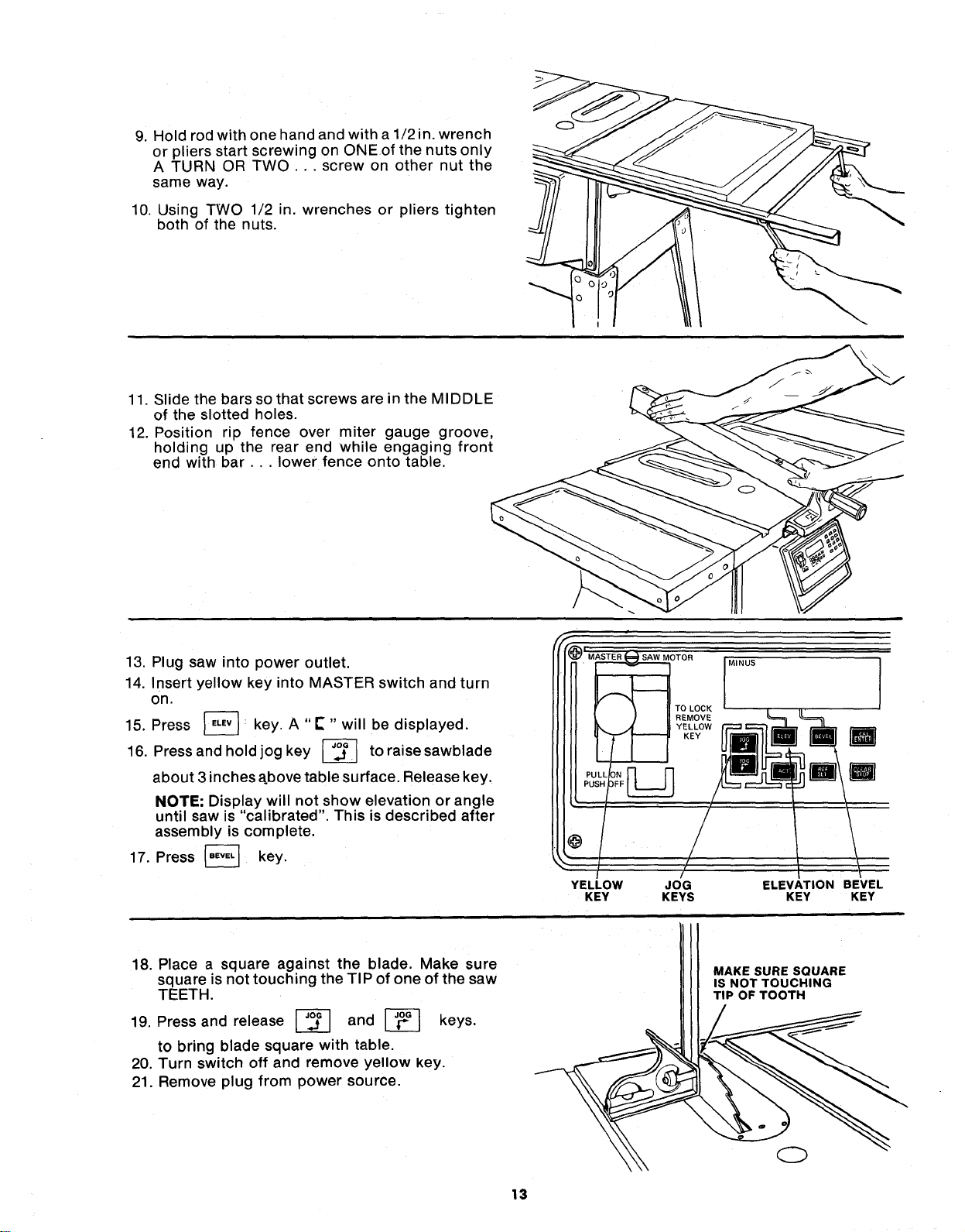
Lay REAR FENCE GUIDE BAR on table to.act.,_S a
straightedge. If outer edge of extension is hig'h'er or
lower than table surface:
A. Slightly loosen nut holding the corner support
bracket to extension using 7/16 in. wrench.
B. Move end of extension up or down until outer
eoge is even with table surface.., check with
GUIDE BAR... tighten nuts.
C. Recheck INNER edge of extension to make sure
it has not moved ... readjust, if necessary.
INSTALLING RIP FENCE GUIDE BARS
1. From among the loose parts find the following
hardware:
2 Hex Head Screws, 5/16-18 x 1-3/4 in. long
2 Hex Head Screws, 5/16-18 x 1 in. long
4 External Lockwashers, 5/16 m.
(approx. dia. of hole 5/16 in.)
4 Hex Nuts, 5/16-18
(approx. dia. of hole 5/16 in.)
2 Spacers, 3/4 in. dia. x 1/2 in. long
2 Self-threading nuts
1 Fence Guide Bar Rod
2. Lay guide bars on saw table.
NOTE: The various holes in the bar allow them
to be positioned on this saw and also makes
them adaptable to other models.
3. Insert a 1-3/4 inch long screw through the
THIRD hole from LEFT IN THE FRONT
BAR... Insert another 1-3/4 inch long screw
through the SEVENTH hole in bar.
4. Place spacers on screws.
REAR GUIDE BAR
7TH HOLE
3RD HOLE
\
\
\ LEFT SIDE
OF FRONT
GUIDE BAR
INSERT BOLTS
5, Turn front bar end for end and insert bolts
through holes in middle and on right side of
front of saw table as illustrated . . . install
Iockwashers and nuts. DON'T SCREW NUTS
ON ALL THE WAY, just get them started on the
screws.
6. Remove the 3 screws from rear of right table
extension.
7. Insert 1 in. long screws in SECOND and
FOURTH holes of rear bar and attach to table
the same way as front bar.
8. Insert ends of FENCE GUIDE BAR ROD
through holes in bars as illustrated.
NOTE: The ends of the ROD are not
threaded.., the SELF THREADING NUTS will
cut threads on the rod as they are screwed on.
FENCE GUIDE
BAR ROD
4TH HOLE
2ND HOLE
12
9. Hold rod with one hand and with a 1/2 in. wrench
or pliers start screwing on ONEof the nuts only
A TURN OR TWO ... screw on other nut the
same way.
10. Using TWO 1/2 in. wrenches or pliers tighten
both of the nuts.
11. Slide the bars so that screws are in the MIDDLE
of the slotted holes.
12. Position rip fence over miter gauge groove,
holding up the rear end while engaging front
end with bar.,, lower fence onto table.
13. Plug saw into power outlet.
14. Insert yellow key into MASTER switch and turn
on.
15. Press _ key. A "E" " will be displayed.
16, Press and hold jog key L__ to
raise sawblade
about 3 inches above table surface. Release key,
NOTE; Display will not show elevation or angle
until saw is "calibrated". This is described after
assembly is complete.
17. Press _ key,
@
YELLOW
KEY
OTOR
TO LOCK
REMOVE
YELLOW
KEY
MINUS
JOG
KEYS
ELEVATION BEVEL
KEY KEY
18. Place a square against the blade. Make sure
square is not touching the TIP of one of the saw
TEETH.
19. Press and release _ and _ keys.
to bring blade square with table.
20. Turn switch off and remove yellow key.
21. Remove plug from power source.
MAKE SURE SQUARE
IS NOT TOUCHING
TIP OF TOOTH
13
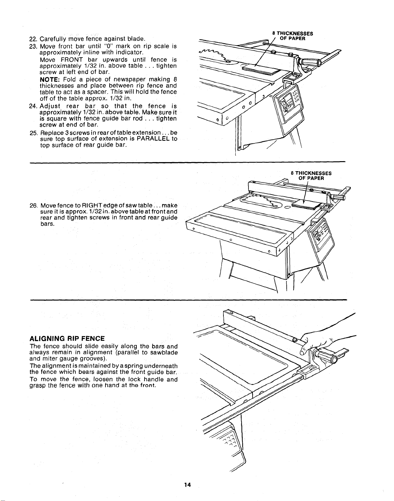
22. Carefully move fence against blade.
23. Move front bar unti,I "0" mark on rip scale is
approximately inline with indicator.
Move FRONT bar upwards until fence is
approximately 1/32 in. above table ... tighten
screw at left end of bar.
NOTE" Fold a piece of newspaper making 8
thicknesses and place between rip fence and
table to act as a spacer. This will hold the fence
off of the table approx. 1/32 n.
24. Adjust rear bar so that the fence is
approximately 1/32 in. above table. Make sure it
is square with fence guide bar rod ... tighten
screw at end of bar.
25. Replace 3 screws in rear of table extension.., be
sure top surface of extension is PARALLEL to
top surface of rear guide bar,
8 THICKNESSES
OF PAPER
\
\
26. Move fence to RIGHTedgeofsawtable .., make
sure it is approx. 1/32 in. above table at front and
rear and tighten screws in front and rearguide
bars.
8 THICKNESSES
ALIGNING RIP FENCE - -_
The fence should slide easily along the bars and
always remain in alignment (parallel to sawblade
and miter gauge grooves).
The alignment is maintained by a spring underneath
the fence which bears against the front guide bar.
To move the fence, loosen the lock handle and
grasp the fence with one hand _t th_ front.
14
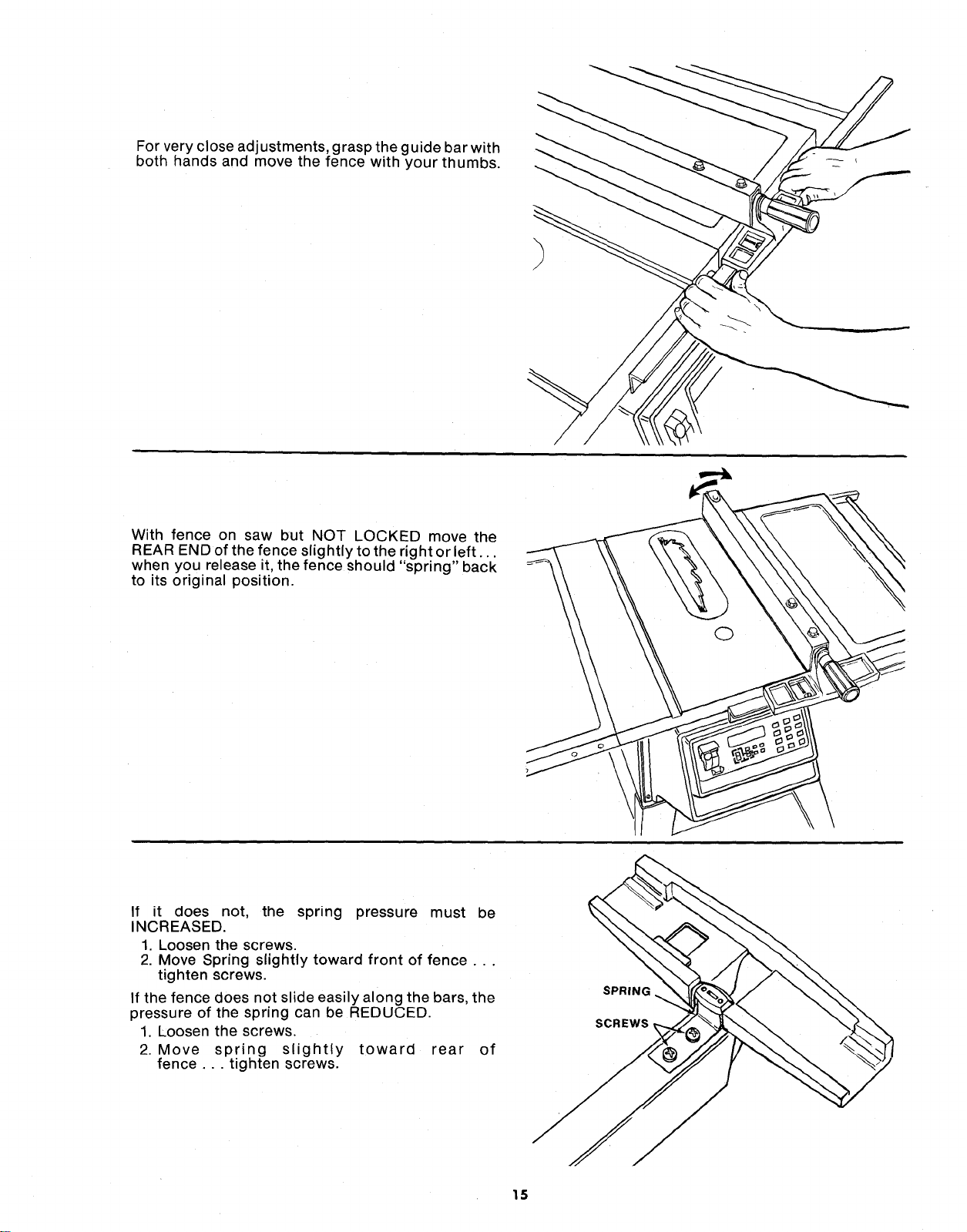
For very close adjustments, grasp the guide bar with
both hands and move the fence with your thumbs.
With fence on saw but NOT LOCKED move the
REAR END of the fence slightly to the right or left...
when you release it, the fence should "spring" back
to its original position.
If it does not, the spring pressure must be
INCREASED.
1. Loosen the screws.
2. Move Spring slightly toward front of fence...
tighten screws.
If the fence does not slide easily along the bars, the
pressure of the spring can be REDUCED.
1. Loosen the screws.
2. Move spring slightly toward rear of
fence ... tighten screws.
SPRING
SCREWS,
15
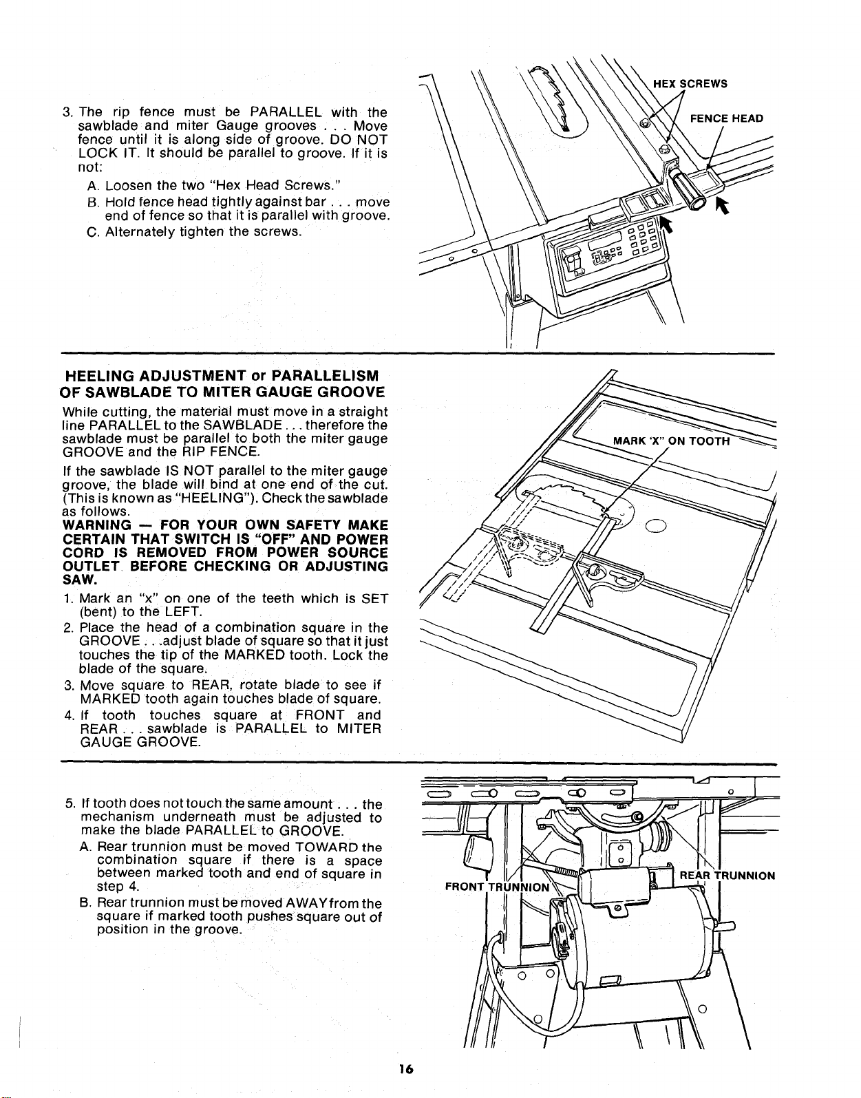
3. The rip fence must be PARALLEL with the
sawblade and miter Gauge grooves ... Move
fence until it is along side of groove. DO NOT
LOCK IT. It should be parallel to groove. If it is
not:
A. Loosen the two "Hex Head Screws."
B. Hold fence head tightly against bar.., move
end of fence so that it is parallel with groove.
C. Alternately tighten the screws.
HEXSCREWS
FENCE HEAD
HEELING ADJUSTMENT or PARALLELISM
OF SAWBLADE TO MITER GAUGE GROOVE
While cutting, the material must move in a straight
line PARALLEL to the SAWBLADE... therefore the
sawblade must be parallel to both the miter gauge
GROOVE and the RIP FENCE.
If the sawblade IS NOT parallel to the miter gauge
groove, the blade will bind at one end of the cut.
(This is known as "HEELING"). Check the sawblade
as follows.
WARNING -- FOR YOUR OWN SAFETY MAKE
CERTAIN THAT SWITCH IS "OFF" AND POWER
CORD IS REMOVED FROM POWER SOURCE
OUTLET BEFORE CHECKING OR ADJUSTING
SAW.
1. Mark an "x" on one of the teeth which is SET
(bent) to the LEFT.
2. Place the head of a combination square in the
GROOVE...adjust blade of square so that it just
touches the tip of the MARKED tooth. Lock the
blade of the square.
3. Move square to REAR, rotate blade to see if
MARKED tooth again touches blade of square.
4. If tooth touches square at FRONT and
REAR ..sawblade is PARALLEL to MITER
GAUGE GROOVE.
5. If tooth does nottouch the same amount.., the
mechanism underneath must be adjusted to
make the blade PARALLEL to GROOVE.
A. Rear trunnion must be moved TOWARD the
combination square if there is a space
between marked tooth and end of square in
step 4.
B. Rear trunnion must be moved AWAYfrom the
square if marked tooth pushessquare out of
position in the groove.
FR(
o
REAR TRUNNION
16
NOTE: All six screws can be reached through back
of saw. Use a 9/16-in. wrench. To reach left-hand
front trunnion screws, tilt blade to approximately
25° . After loosening screws reposition blade at 90° .
To make this adjustment:
a. Plug saw into power outlet.
b. Insert yellow key into MASTER switch and
turn on.
c. Press [-_ key.
d. Press and hold _-_ key to tilt sawbladeto
approximately 25° to obtain clearance for
wrench.
e. Turn switch off. Remove yellow key.
f. Loosen all three screws that hold the rear
trunnion and all three screws that hold the
front trunnion.
g. Insert yellow key into MASTER switch and
turn on.
h. Press [-_ key.
i. Press and hold _ keyto reposition blade
at 90° using a square.
j. Turn switch "OFF", remove yellow key and
unplug saw.
REAR TRUNNION
SCREWS
.EFT--HAND
RIGHT HAND CENTER (BEHIND HERE)
(BEHIND HERE)
! \
FRONT-TRUNNION SCREWS
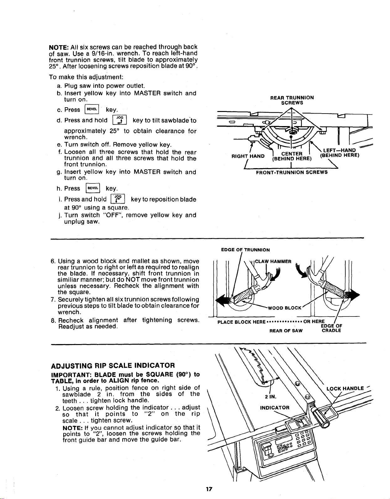
6. Using a wood block and mallet as shown, move
rear trunnion to right or left as required to realign
the blade. If necessary, shift front trunnion in
similiar manner; but do NOT move front trunnion
unless necessary. Recheck the alignment with
the square.
7. Securely tighten all six trunnion screws following
previous steps to tilt blade to obtain clearance for
wrench.
8. Recheck alignment after tightening screws.
Readjust as needed.
EDGE OF TRUNNION
CLAW HAMMER
PLACE BLOCK HERE .... • • • • • • • •" • OR HERE
EDGE OF
REAR OF SAW CRADLE
ADJUSTING RIP SCALE INDICATOR
IMPORTANT: BLADE must be SQUARE (90 °) to
TABLE, in order to ALIGN rip fence.
1. Using a rule, position fence on right side of
sawblade 2 in. from the sides of the
teeth ... tighten lock handle.
2. Loosen screw holding the indicator.., adjust
so that it points to "2" on the rip
scale.., tighten screw.
NOTE: If you cannot adjust indicator so that it
points to "2", loosen the screws holding the
front guide bar and move the guide bar.
\
LOCK HANDLE _
17
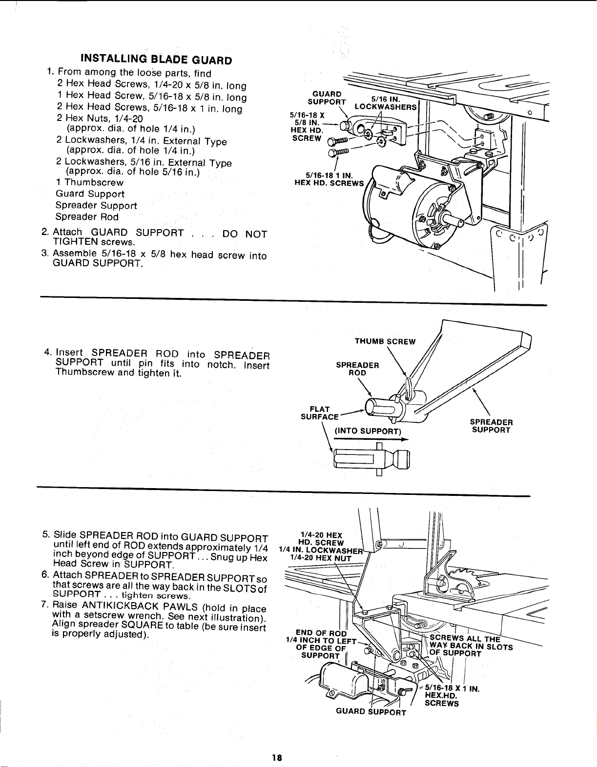
INSTALLINGBLADEGUARD
1. From among the loose parts, find
2 Hex Head Screws, 1/4-20 x 5/8 in. long
1 Hex Head Screw, 5/16-18 x 5/8 in. long
2 Hex Head Screws, 5/16-18 x 1 in. long
2 Hex Nuts, 1/4-20
(approx. dia. of hole 1/4 in.)
2 Lockwashers, 1/4 in. External Type
(approx. alia. of hole 1/4 in.)
2 Lockwashers. 5/16 in. External Type
(approx. dia. of hole 5/16 in.)
1 Thumbscrew
Guard Support
Spreader Support
Spreader Rod
2. Attach GUARD SUPPORT
TIGHTEN screws.
3. Assemble 5/16-18 x 5/8 hex head screw
GUARD SUPPORT.
DO NOT
into
G UARDT_L OC_(_/_S'_HERS "-
5/16-18 X
5/8 IN.
HEX HD. _" \
SCREW
/
5116-18 1 IN.
HEX HD. SCREWS/
-
4. Insert SPREADER ROD into SPREADER
SUPPORT until pin fits into notch. Insert
Thumbscrew and tighten it.
THUMB SCREW
\
SPREADER _
ROD
FLAT
SURFACE
(INTO SUPPORT)
\ n "
II
\
\,
SPREADER
SUPPORT
5. Slide SPREADER ROD into GUARD SUPPORT
until left end of ROD extends approximately 1/4
inch beyond edge of SUPPORT. ,: Snug up Hex
Head Screw in SUPPORT.
6. Attach SPREADER to SPREADER SUPPORT so
that screws are all the way back in the SLOTS of
,_qUPPORT . . . tighten screws.
7. Raise ANTIKICKBACK PAWLS (hold in place
with a setscrew wrench. See next illustration).
Align spreader SQUARE to table (be sure insert
is properly adjusted).
1/4-20 HEX J
114,"%'c%%. J
1/4 iNCH TO LEFT_ _, \1_ \\ WAY. BACK IN SLOTS
OF EDGE OF, (_ _ OF SUPPORT
_ _ / SCREWS
GUARD SUPPORT
18
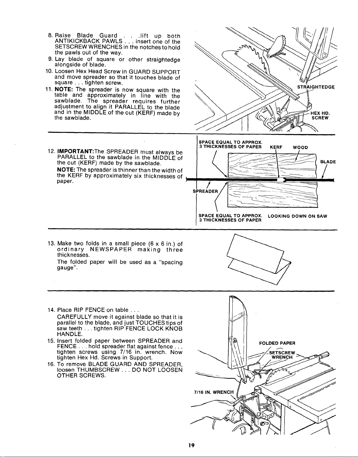
8. Raise Blade Guard .lift up both
ANTIKICKBACK PAWLS'... insert one of the
SETSCREW WRENCHES in the notches to hold
the pawls out of the way.
9. Lay blade of square or other straightedge
alongside of blade.
10. Loosen Hex Head Screw in GUARD SUPPORT
and move spreader so that it touches blade of
square ... tighten screw.
11. NOTE: The spreader is now square with the
table and approximately in line with the
sawblade. The spreader requires further
adjustment to align it PARALLEL to the blade
and in the MIDDLE of the cut (KERF) made by
the sawblade.
\
STRAIGHTEDGE
HD.
SCREW
12. IMPORTANT:The SPREADER must always be
PARALLEL to the sawblade in the MIDDLE of
the cut (KERF) made by the sawblade.
NOTE: The spreader is thinner than the width of
the KERF by approximately six thicknesses of _
paper.
SPACE EQUAL TO APPROX. LOOKING DOWN ON SAW
3 THICKNESSES OF PAPER
BLADE
/
t
13. Make two folds in a small piece (6 x 6 in.) of
ordinary NEWSPAPER making three
thicknesses.
The folded paper will be used as a "spacing
gauge".
14. Place RIP FENCE on table,..
CAREFULLY move it against blade so that it is
parallel to the blade, and just TOUCHES tips of
saw teeth.., tighten RIP FENCE LOCK KNOB
HANDLE.
15. Insert folded paper between SPREADER and
FENCE... hold spreader flat against fence...
tighten screws using 7/16 in. wrench. Now
tighten Hex Hd. Screws in Support.
16. To remove BLADE GUARD AND SPREADER,
loosen THUMBSCREW... DO NOT LOOSEN
OTHER SCREWS.
7/16 IN. WRENCH
FOLDED PAPER
19
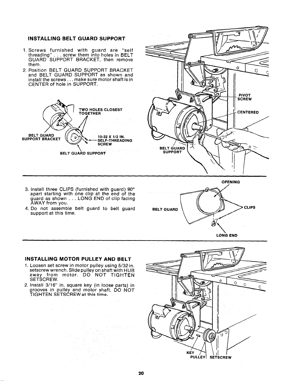
INSTALLING BELT GUARD SUPPORT
1. Screws furnished with guard are "self
threading".. , screw them into holes in BELT
GUARD SUPPORT BRACKET, then remove
them.
2. Position BELT GUARD SUPPORT BRACKET
and BELT GUARD SUPPORT as shown and
install the screws.., make sure motor shaft is in
CENTER of hole in SUPPORT,
TWO HOLES CLOSEST
TOGETHER
BELT GUARD _ 10-32 X 1/2 IN.
SUPPORT BRACKET _\%%.,_.__SELF.THREADING
SCREW
\
BELT GUARD SUPPORT
/
BELT GUARD
SUPPORT
3. Install three CLIPS (furnished with guard) 90°
apart starting with one clip at the end of the
guard as shown . . . LONG END of clip facing
AWAY from you.
4. Do not assemble belt guard to belt guard
support at this time.
BELT GUARD
\
\
OPENING
LONG END
INSTALLING MOTOR PULLEY AND BELT
1 Loosen set screw in motor pulley using 5/32 in.
setscrew wrench. Slide pulley on shaft with HUB
away from motor. DO NOT TIGHTEN
SETSCREW,
2, Install 3/16" in, square key (in loose parts) in
grooves in pulley and motor shaft. DO NOT
TIGHTEN SETSCRI::Wat this time.
KEY
PULLEY
J
SETSCREW
2O
3. Loosen two motor base clamp screws.., push
motor in as far as it will go.
4. a. Plug in saw, turn MASTER switch "ON".
b. Press _ key.
c. Press and hold L__ key to lower blade even
with table top.
d. Turn MASTER switch "OFF", remove yellow key
and unplug saw.
5. Install belt on motor pulley and saw pulley.
6. Sight along edges of both pulleys and move
motor pulley so that belt is parallel to the edges
of both pulleys.., tighten the setscrew in the
motor pulley.
7. Make sure blade is 90 ° to table.., raise it all the
way up using procedure in Step 4 except holding
the [_ key.
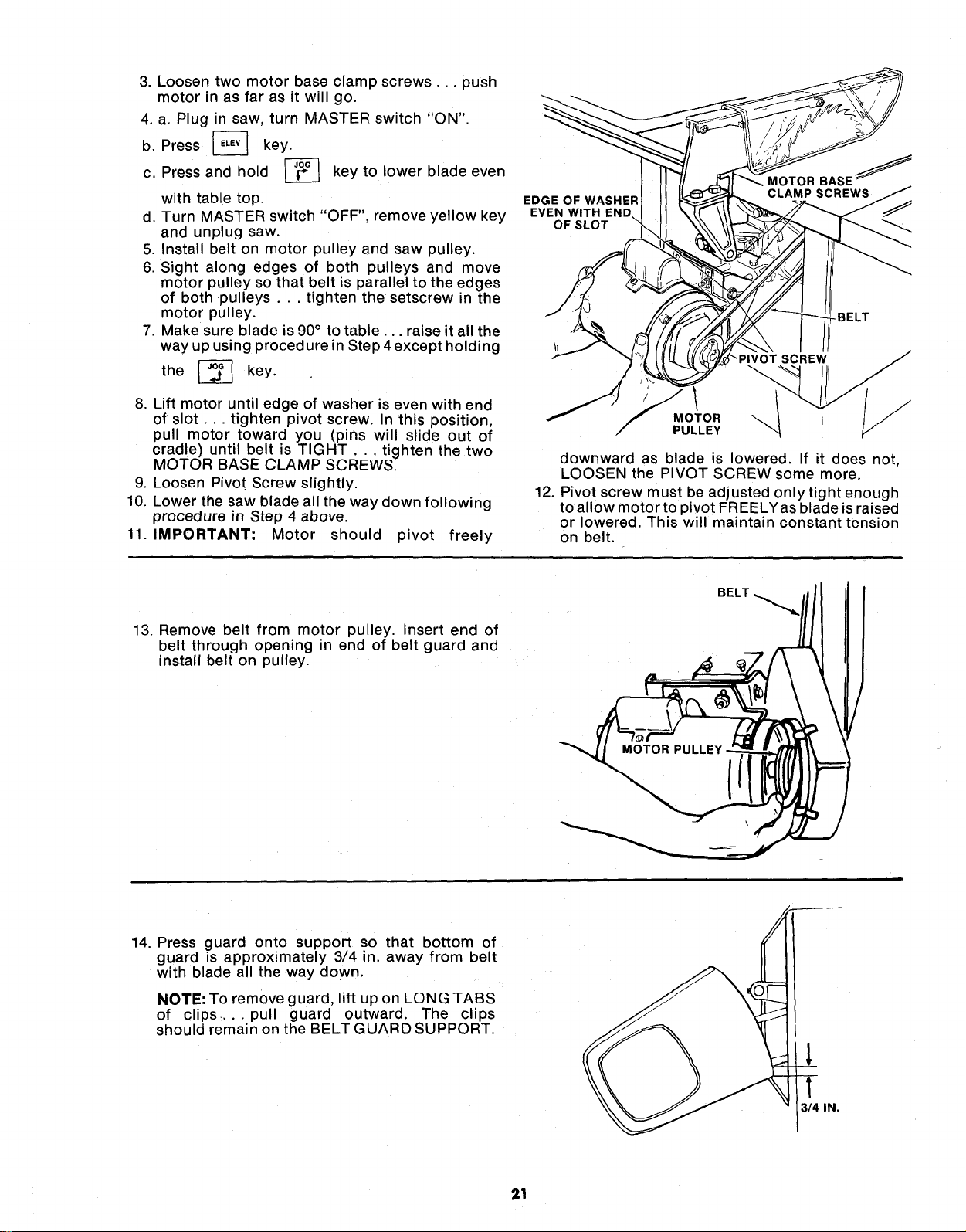
8. Lift motor until edge of washer is even with end
of slot.., tighten pivot screw. In this position,
pull motor toward you (pins will slide out of
cradle) until belt is TIGHT... tighten the two
MOTOR BASE CLAMP SCREWS.
9. Loosen Pivot Screw slightly.
10. Lower the saw blade all the way down following
procedure in Step 4 above.
11. IMPORTANT-" Motor should pivot freely
EDGE OF WASHER
EVEN WITH END
OF SLOT
MOTOR BASE j
-BELT
_PIVOT SCREW
MOTOR
PULLEY
downward as blade is lowered. If it does not,
LOOSEN the PIVOT SCREW some more.
12. Pivot screw must be adjusted onlytight enough
to allow motor to pivot FREELYas blade is raised
or lowered. This will maintain constant tension
on belt.
13. Remove belt from motor pulley. Insert end of
belt through opening in end of belt guard and
nstall belt on pulley.
BELT
14. Press guard onto support so that bottom of
guard is approximately 3/4 in. away from belt
with blade all the way down.
NOTE: To remove guard, lift up on LONG TABS
of clips .... pull guard outward. The clips
should remain on the BELT GUARD SUPPORT.
l
1
314 IN.
21
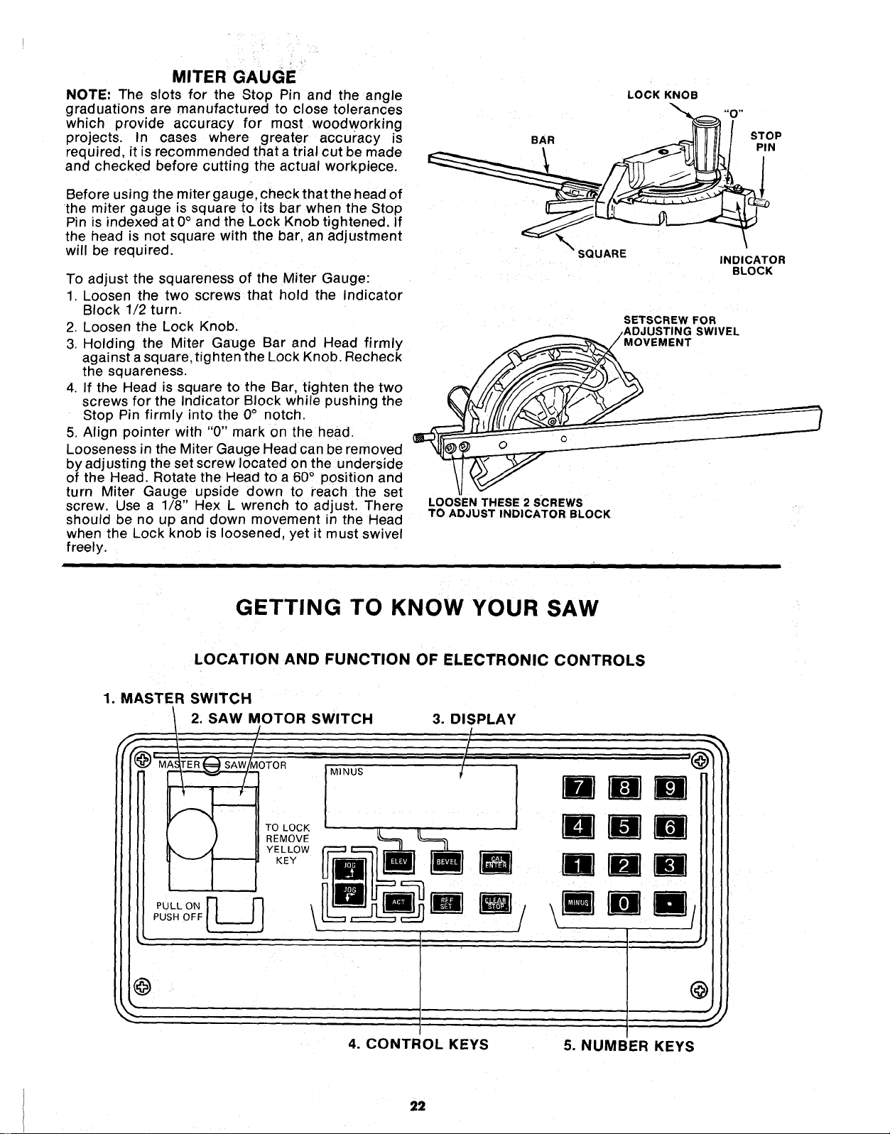
MITER GAUGE
NOTE: The slots for the Stop Pin and the angle
graduations are manufactured to close tolerances
which provide accuracy for most woodworking
projects. In cases where greater accuracy is
required, it is recommended thata trial cut be made
and checked before cutting the actual workpiece.
Before using the miter gauge, check that the head of
the miter gauge is square to its bar when the Stop
Pin is indexed at 0° and the Lock Knob tightened. If
the head is not square with the bar, an adjustment
will be required.
To adjust the squareness of the Miter Gauge:
1. Loosen the two screws that hold the Indicator
Block 1/2 turn.
2. Loosen the Lock Knob.
3. Holding the Miter Gauge Bar and Head firmly
against a square, tighten the Lock Knob. Recheck
the squareness.
4. If the Head is square to the Bar, tighten the two
screws for the Indicator Block while pushing the
Stop Pin firmly into the 0° notch.
5. Align pointer with "0" mark on the head.
Looseness in the Miter Gauge Head can be removed
by adjusting the set screw located on the underside
of the Head. Rotate the Head to a 60° position and
turn Miter Gauge upside down to reach the set
screw. Use a 1/8" Hex L wrench to adjust. There
should be no up and down movement in the Head
when the Lock knob is loosened, yet it must swivel
freely.
LOCK KNOB
BAR STOP
PIN
SQUARE
INDICATOR
BLOCK
SETSCREW FOR
/ADJUSTING SWIVEL
MOVEMENT
LOOSEN THESE 2 SCREWS
TO ADJUST INDICATOR BLOCK
GETTING TO KNOW YOUR SAW
LOCATION AND FUNCTION OF ELECTRONIC CONTROLS
1. MASTER SWITCH
2. SAW MOTOR SWITCH 3. DISPLAY
4. CONTROL KEYS
5. NUMBER KEYS
22
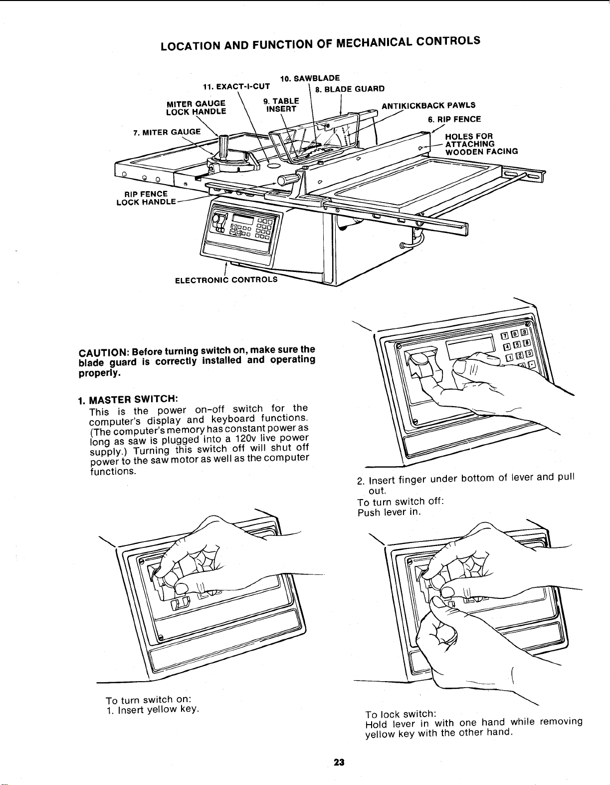
LOCATION AND FUNCTION OF MECHANICAL CONTROLS
10. SAWBLADE
11. EXACT-I-CUT
MITER GAUGE \ 9. TABLE
LOCK HANDLE \ INSERT
7, MITER GAUGE
8. BLADE GUARD
ANTIKICKBACK PAWLS
6. RIP FENCE
HOLES FOR
ATTACHING
WOODEN FACING
RIP FENCE
LOC
ELECTRONIC CONTROLS
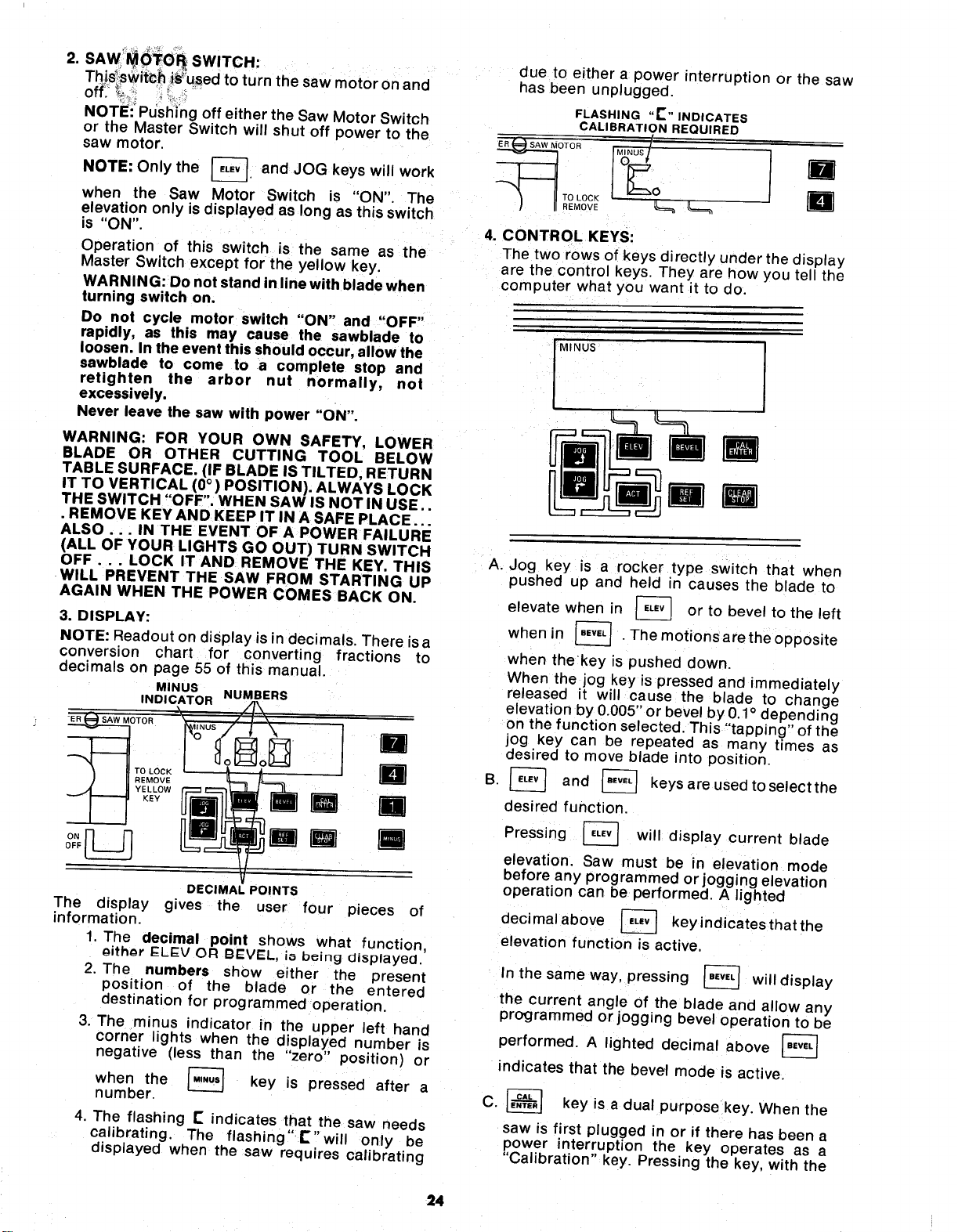
CAUTION: Before turning switch on, make sure the
blade guard is correctly installed and operating
properly.
1. MASTER SWITCH:
This is the power on-off switch for the
computer's display and keyboard functions.
(The computer's memory has constant power as
long as saw is plugged into a 120v live power
supply.) Turning this switch off will shut off
power to the saw motor as well as the computer
functions.
2. Insert finger under bottom of lever and pull
out.
To turn switch off:
Push lever in.
To turn switch on:
1. Insert yellow key.
To lock switch:
Hold lever in with one hand while removing
yellow key with the other hand.
23
.
SAW_()_TO_ SWITCH:
Thi,s_swit_h i_used to turn the saw motor on and
off___,,_ '_L .__
NOTE:_Pdsl_i_ingoff either the Saw Motor Switch
or the Master Switch will shut off power to the
saw motor.
NOTE: Only the _-]. and JOG keys
will
work
when the Saw Motor Switch is "ON". The
elevation only is displayed as long as this switch
is "ON".
Operation of this switch is the same as the
Master Switch except for the yellow key.
WARNING: Do not stand in line with blade when
turning switch on.
Do not cycle motor switch "ON" and "OFF"
rapidly, as this may cause the sawblade to
loosen. In the event this should occur, allow the
sawblade to come to a complete stop and
retighten the arbor nut normally, not
excessively.
Never leave the saw with power "ON".
The display
information.
WARNING: FOR YOUR OWN SAFETY, LOWER
BLADE OR OTHER CUTTING TOOL BELOW
TABLE SURFACE. (IF BLADE IS TILTED, RETURN
IT TO VERTICAL (0°) POSITION). ALWAYS LOCK
THE SWITCH "OFF". WHEN SAW IS NOT IN USE..
• REMOVE KEY AND KEEP IT IN A SAFE PLACE...
ALSO... IN THE EVENT OF A POWER FAILURE
(ALL OF YOUR LIGHTS GO OUT) TURN SWITCH
OFF... LOCK IT AND REMOVE THE KEY. THIS
WILL PREVENT THE SAW FROM STARTING UP
AGAIN WHEN THE POWER COMES BACK ON.
3. DISPLAY:
NOTE: Readout on display is in decimals. There isa
conversion chart for converting fractions to
decimals on page 55 of this manual.
MINUS
INDICATOR NUMBERS
OTOR
li
) II °#°vC n
DECIMAL POINTS
gives the user four pieces of
1. The decimal point shows what function,
oithor I::LEV OR BEVEL, io b_ing displayed.
2. The numbers show either the present
position of the blade or the entered
destination for programmed operation.
3. The minus indicator in the upper left hand
corner lights when the displayed number is
negative (less than the "zero" position) or
when the _ key is pressed after a
number.
4. The flashing IS indicates that the saw needs
calibrating. The flashing" E" will only be
displayed when the saw requires calibrating
due to either a power interruption or the saw
has been unplugged.
FLASHING "P" INDICATES
CALIBRATION REQUIRED
_OTOR __ -
4. CONTROL KEYS:
The two rows of keys directly under the display
are the control keys. They are how you tell the
computer what you want it to do.
MINUS
A. Jog key is a rocker type switch that when
pushed up and held in causes the blade to
elevate when in _ or to bevel to the left
when in _ .Themotionsaretheopposite
when thekey is pushed down.
When the jog key is pressed and immediately
released it will cause the blade to change
elevation by 0.005" or bevel by 0.1° depending
on the function selected. This "'tapping" of the
jog key can be repeated as many times as
desired to move blade into position.
B. _ and _ keys are used to select the
desired function,
Pressing _ will display current blade
elevation. Saw must be in elevation mode
before any programmed or
. jogging elevation
operation can be pertormed. A lighted
decimal above [_ key indicates that the
elevation function is active,
In the same way, pressing _ will display
the current angle of the blade and allow any
programmed or jogging bevel operation to be
performed. A lighted decimal above [_
indicates that the bevel mode is active
C. _ key is a dual purpose key. When the
saw is first plugged in or if there has been a
power interruption the key operates as a
"Calibration" key. Pressing the key, with the
24
blade at 90 ° to the table and at zero elevation
accurately sets the program that computes
the elevation and bevel angle of the blade.
Once the calibration has been set the key
becomes an "Enter" key used for entering
both a bevel and an elevation programmed
motion.
D. The _ key, when pressed, will starta
programmed motion.
It becomes inactive while the saw motor is
"ON".
E The _ keywillsetthedisplaytoa"zero"
point other than at the table top, or when
using a cutting tool less than 10 inches in
diameter. See "Calibrating the Saw for
Electronic Operations" Page 29.
F. The _ key will clear the display if an
error is made in a programmed entry and will
return the display to the current position of
the chosen function. This key will also stop a
programmed motion once begun and clear
the original destination.
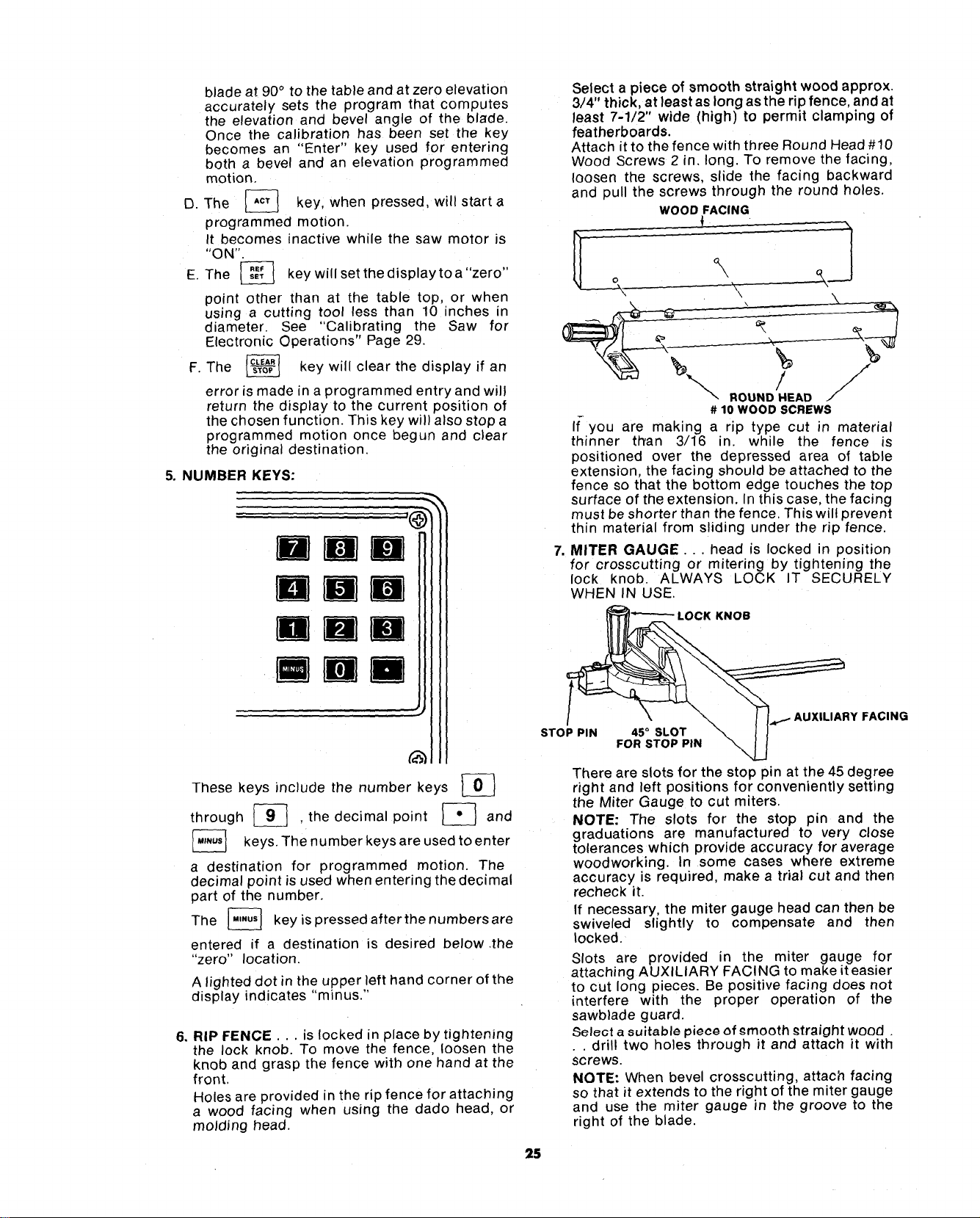
5. NUMBER KEYS:
Bmm
mmM
Rim
mMD
These keys include the number keys _}
through _ . the decimal point _ and
The number used to enter
keys,
keys
are
a destination for programmed motion. The
decimal point is used when entering the decimal
part of the number.
The [_ key ispressedafterthenumbersare
entered if a destination is desired below •the
"zero" location
A lighted dot in the upper left hand corner of the
display indicates "min us."
6. RIP FENCE... is locked in place by tightening
the lock knob. To move the fence, loosen the
knob and grasp the fence with one hand at the
front,
Holes are provided in the rip fence for attaching
a wood facing when using the dado head, or
molding head.
Select a piece of smooth straight wood approx.
3/4" thick, at least as long as the rip fence, and at
least 7-1/2" wide (high) to permit clamping of
featherboards.
Attach it to the fence with three Round Head #10
Wood Screws 2 in. long. To remove the facing,
loosen the screws, slide the facing backward
and pull the screws through the round holes.
WOOD FACING
'\
,/ j/"/
ROUND HEAD ./
# 10 WOOD SCREWS
If-you are making a np type cut in material
thinner titan 3/16 in. while the fence is
positioned over the depressed area of table
extension, the facing should be attached to the
fence so that the bottom edge touches the top
surface of the extension• In this case, the facing
must be shorter than the fence. This will prevent
thin material from sliding under the rip fence.
,
MITER GAUGE... head is locked in position
for crosscutting or mitering by tightening the
lock knob. ALWAYS LOCK IT SECURELY
WHEN IN USE.
LOCK KNOB
\
STOP PIN 45 ° SLOT \
FOR STOP PIN
\
AUXILIARY FACING
There are slots for the stop pin at the 45 degree
right and left positions for conveniently setting
the Miter Gauge to cut miters.
NOTE: The slots for the stop pm and the
graduations are manufactured to very close
tolerances which provide accuracy for average
woodworking. In some cases where extreme
accuracy is required make a trial cut and then
recheck it.
If necessary, the miter gauge head can then be
swiveled slightly to compensate and then
locked.
Slots are provided in the miter gauge for
attaching AUXILIARY FACING to make it easier
to cut long pieces• Be positive facing does not
interfere with the proper operation of the
sawblade guard.
Select a suitable piece of emooth _traight wood
• . drill two holes through it and attach it with
screws.
NOTE: When bevel crosscutting, attach facing
so that it extends to the right of the miter gauge
and use the miter gauge rn the groove to the
right of the blade.
25
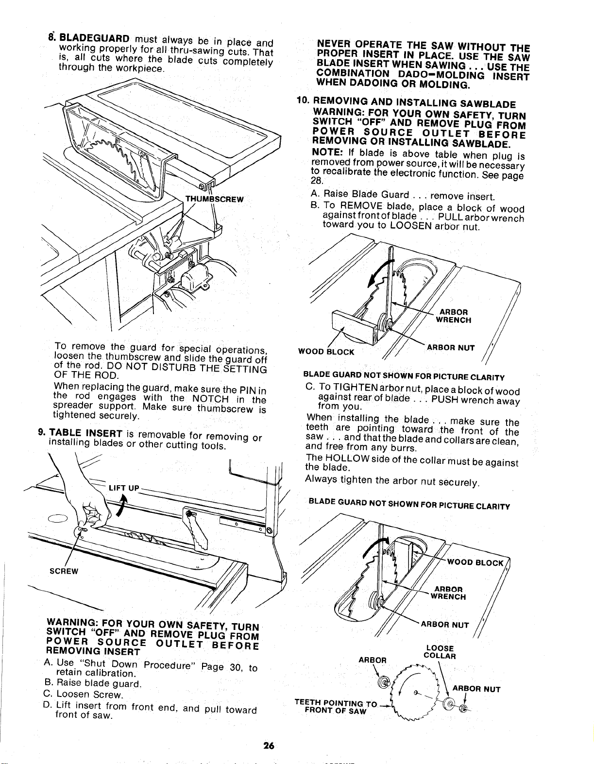
8_,BLADEGUARD must always be in place and
working properly for all thru-sawing cuts That
fs, all cuts where ,the blade cuts completely
through the workpiece.
THUMBSCREW
\
\
To remove the guard for special operations,
loosen the thumbscrew and slide the guard off
of the rod. DO NOT DISTURB THE SETTING
OF THE ROD.
When replacing the guard, make sure the PIN m
the rod engages with the NOTCH in the
spreader support. Make sure thumbscrew is
tightened securely.
9. TABLE INSERT is removable for removing or
installing blades or other cutt ng tools.
WARNING: FOR YOUR OWN SAFETY, TURN
SWITCH "OFF" AND REMOVE PLUG FROM
POWER SOURCE OUTLET BEFORE
REMOVING INSERT
A. Use "Shut Down Procedure" Page 30, to
retain calibration.
B. Raise blade guard.
C. Loosen Screw.
D. Lift insert from front end. and pull toward
front of saw.
NEVER OPERATE THE SAW WITHOUT THE
PROPER INSERT IN PLACE. USE THE SAW
BLADE INSERT WHEN SAWING . . . USE THE
COMBINATION DADO-MOLDING INSERT
WHEN DADOING OR MOLDING.
10. REMOVING AND INSTALLING SAWBLADE
WARNING: FOR YOUR OWN SAFETY, TURN
SWITCH "OFF" AND REMOVE PLUG FROM
POWER SOURCE OUTLET BEFORE
REMOVING OR INSTALLING SAWBLADE.
NOTE: If blade is above table when plug is
removed from power source, it will be necessary
to recalibrate the electronic function. See page
28.
A. Raise Blade Guard .. remove insert.
B. To REMOVE blade, place a block of wood
against front of blade... PULL arbor wrench
toward you to LOOSEN arbor nut.
WOOD BLOCK
/
BLADE GUARD NOT SHOWN FOR PICTURE CLARITY
C. To TIGHTEN arbor nut, place a block of wood
against rear of blade .. PUSH wrench away
from you.
When installing the blade.., make sure the
teeth are pointing toward the front of the
saw.., and that the b ade and collars are clean,
and free from any burrs.
The HOLLOW side of the collar must be against
the blade.
Always tighten the arbor nut securely.
BLADE GUARD NOT SHOWN FOR PICTURE CLARITY
BLOCK
BOR NUT
LOOSE
ARBOR COLLAR
T,,T,PO'NT,NGT
FRONT OF SA_,f "_, / _(_
26
NOTE:When using the Dado or Molding Head, it is
not necessary to install the loose collar. Refer to
instruction sheet packed with dado or molding
head.
To replace insert.
Place insert into insert opening in table and
push toward rear of saw to engage spring clip
and until keyslot in insert will drop over screw.
Tighten screw.
Do not tighten screw to the point where it will
deflect the insert.
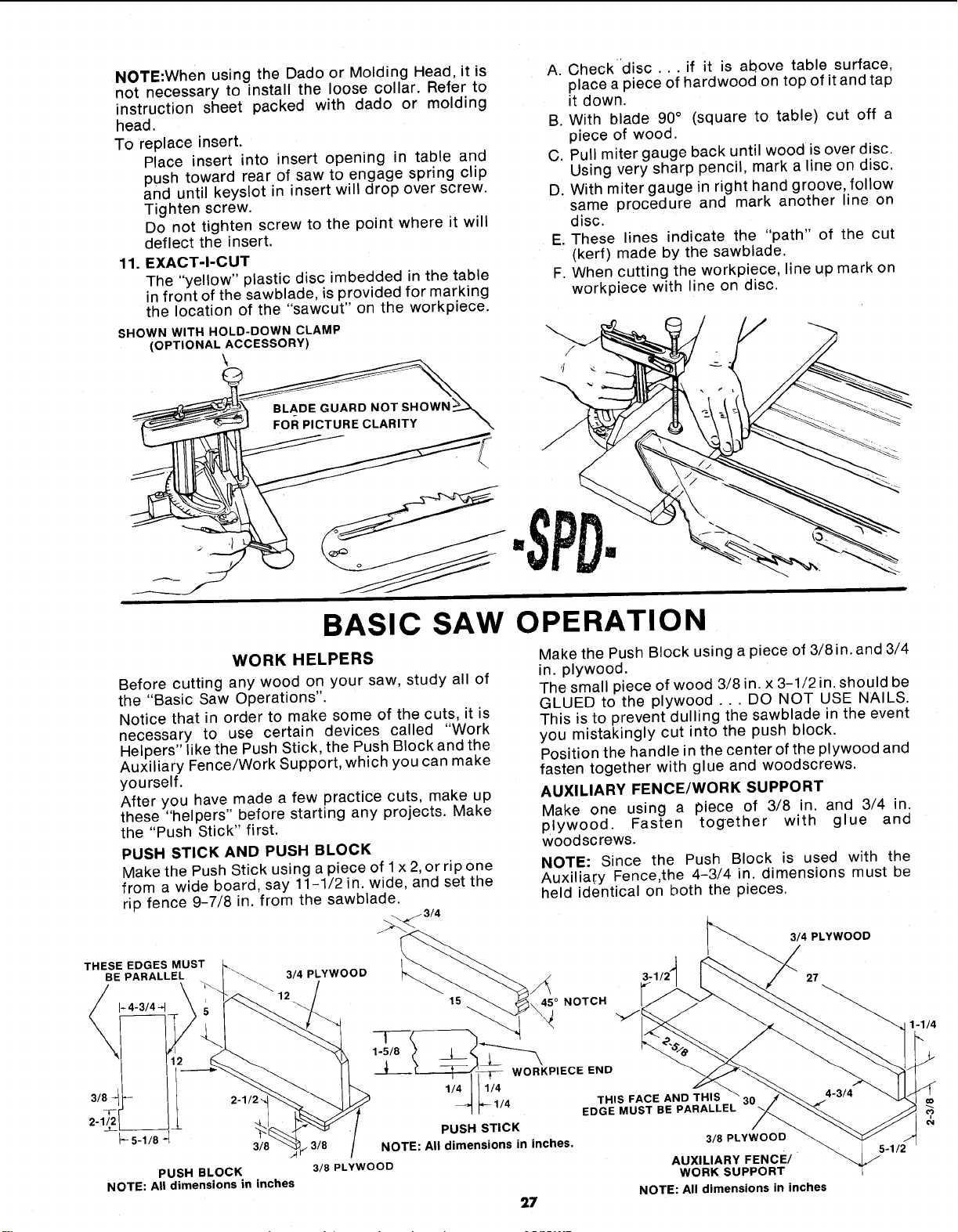
11. EXACT-I-CUT
The "yellow" plastic disc imbedded in the table
in front of the sawblade, is provided for marking
the location of the "sawcut" on the workpiece.
SHOWN WITH HOLD-DOWN CLAMP
(OPTIONAL ACCESSORY)
A. Checkdisc... if it is above table surface,
place a piece of hardwood on top of it and tap
it down.
B. With blade 90° (square to table) cut off a
piece of wood.
C. Pull miter gauge back until wood is over disc.
Using very sharp pencil, mark a line on disc.
D. With miter gauge in right hand groove, follow
same procedure and mark another line on
disc.
E. These lines indicate the "path" of the cut
(kerf) made by the sawblade.
F. When cutting the workpiece, line up mark on
workpiece with line on disc.
BASIC SAW OPERATION
WORK HELPERS
Before cutting any wood on your saw, study all of
the "Basic Saw Operations".
Notice that in order to make some of the cuts, it is
necessary to use certain devices called "Work
Helpers" like the Push Stick, the Push Block and the
Auxiliary Fence/Work Support, which you can make
yourself.
After you have made a few practice cuts, make up
these "helpers" before starting any projects. Make
the "Push Stick" first.
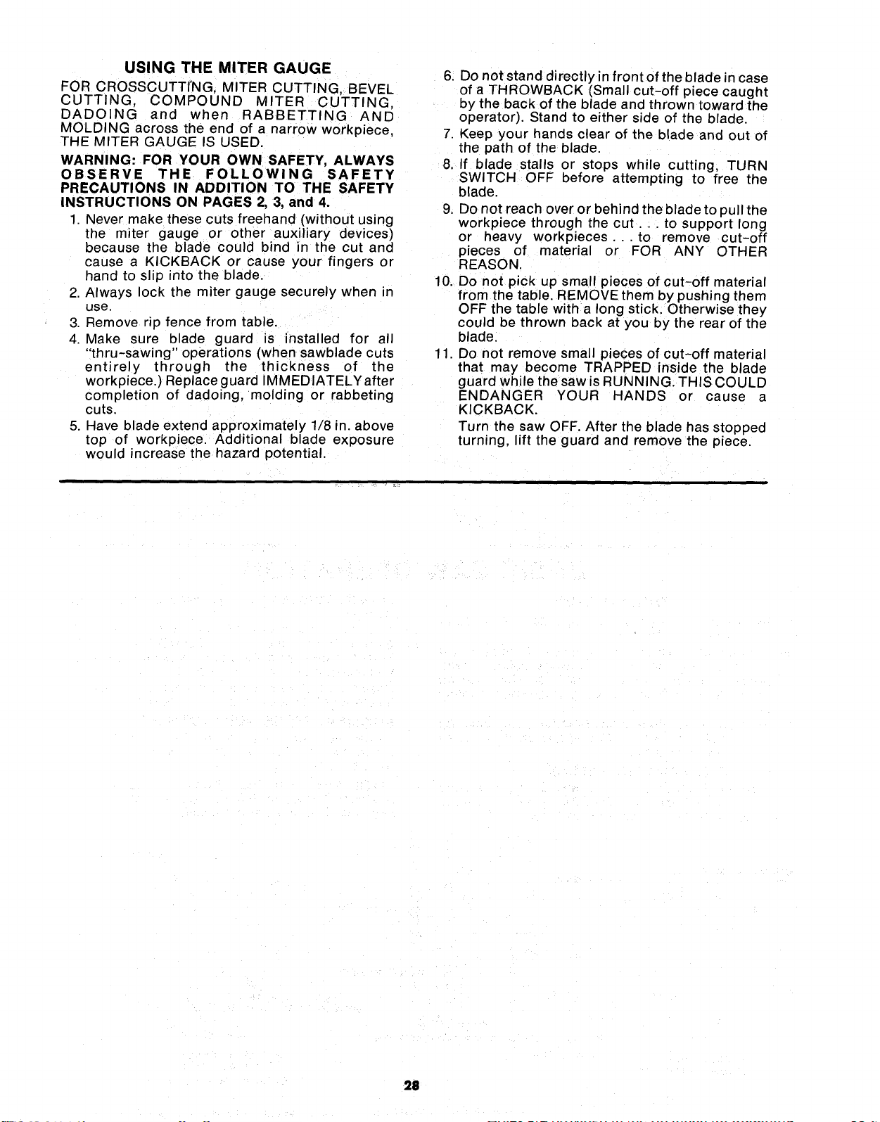
PUSH STICK AND PUSH BLOCK
Make the Push Stick using a piece of 1x 2,or rip one
from a wide board, say 11-1/2 in. wide, and set the
rip fence 9-7/8 in. from the sawblade.
Make the Push Block using a piece of 3/8in. and 3/4
in. plywood.
The small piece of wood 3/8 in. x 3-1/2 in. should be
GLUED to the plywood ... DO NOT USE NAILS.
This is to prevent dulling the sawblade in the event
you mistakingly cut into the push block.
Position the handle in the center of the plywood and
fasten together with glue and woodscrews.
AUXILIARY FENCE/WORK SUPPORT
Make one using a piece of 3/8 in. and 3/4 in.
plywood. Fasten together with glue and
woodscrews.
NOTE: Since the Push Block is used with the
Auxilia_:y Fence,the 4-3/4 in. dimensions must be
held identical on both the pieces.
THESE EDGES MUST
BE PARALLEL 3/4 PLYWOOD
3/4 PLYWOOD
PUSH BLOCK
NOTE: All dimensions in inches
45 ° NOTCH
27
t
1-5/8
NOTE: All dimensions in inches.
3/8 PLYWOOD
t _-- WORKPIECE END
111/4
I_- 1/4 THIS FACE AND THIS
/
EDGE MUST BE PARALLEL
PUSH STICK
3/8 PLYWOOD
27
AUXILIARY FENCE/
WORK SUPPORT
NOTE: All dimensions in inches
USING THE MITER GAUGE
FOR CROSSCUTTING, MITER CUTTING, BEVEL
CUTTING, COMPOUND MITER CUTTING,
DADOING and when RABBETTING AND
MOLDING across the end of a narrow workpiece,
THE MITER GAUGE IS USED.
WARNING: FOR YOUR OWN SAFETY, ALWAYS
OBSERVE THE FOLLOWING SAFETY
PRECAUTIONS IN ADDITION TO THE SAFETY
INSTRUCTIONS ON PAGES 2, 3, and 4.
1 Never make these cuts freehand (without using
the miter gauge or other auxiliary devices)
because the blade could bind in the cut and
cause a KICKBACK or cause your fingers or
hand to slip into the blade.
2. Always lock the miter gauge securely when in
use.
3. Remove rip fence from table.
4. Make sure blade guard is installed for all
"thru-sawing" operations (when sawblade cuts
entirely through the thickness of the
workpiece.) Replace guard IMMEDIATELYafter
completion of dadoing, molding or rabbeting
cuts.
5. Have blade extend approximately 1/8 in. above
top of workpiece. Additional bade exposure
would increase the hazard potential.
6. Do not stand directly in front of the blade in case
of a THROWBACK (Small cut-off piece caught
by the back of the blade and thrown toward the
operator). Stand to either side of the blade.
7. Keep your hands clear of the blade and out of
the path of the blade.
8. If blade stalls or stops while cutting, TURN
SWITCH OFF before attempting to free the
blade.
9. Do not reach over or behind the blade to pull the
workpiece through the cut.., to support long
or heavy workp_eces...to remove cut-off
pieces of material or FOR ANY OTHER
REASON.
10. Do not pick up small pieces of cut-off material
from the table. REMOVE them by pushing them
OFF the table with a long stick. Otherwise they
could be thrown back at you by the rear of the
blade.
11. Do not remove small pieces of cut-off material
that may become TRAPPED inside the blade
guard while the saw is RUNNING. THIS COULD
ENDANGER YOUR HANDS or cause a
KICKBACK.
Turn the saw OFF. After the blade has stopped
turning, lift the guard and remove the piece.
211
CALIBRATING THE SAW
FOR ELECTRONIC OPERATIONS
Whenever the saw has been unplugged or there has
been an interruption in power, it will be necessaryto
calibrate the "zero" points for the elevation and
bevel operations. To do this, perform the steps listed
below.
NOTE: For calibrating the saw with a sawblade or
other cutting tool that is less the 10" in diameter
refer to the section headed "Calibration Procedure
for Cutting Tools Less then 10" Diameter" page 30.
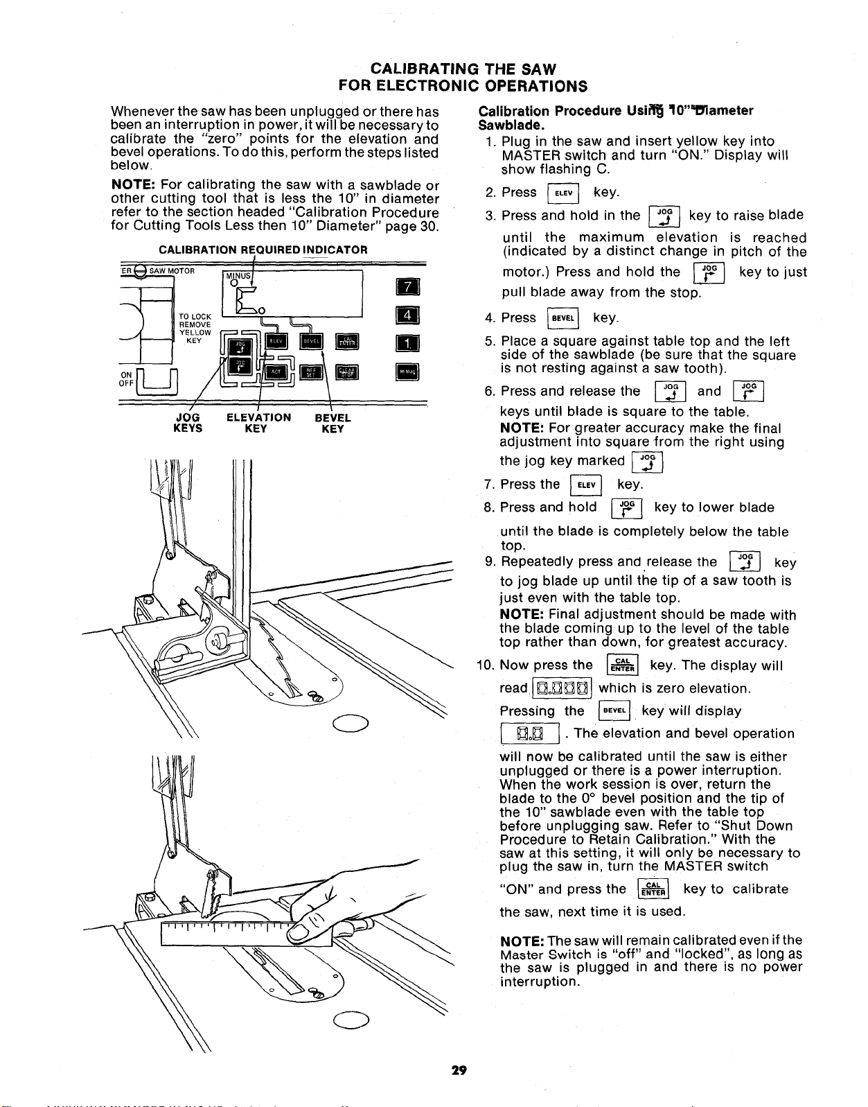
CALIBRATION REQUIRED INDICATOR
l
TOR MINUSI(_O
ELEVATION
KEY
U
BEVEL
KEY
D
R
n
R
\
OFF
JOG
KEYS
Calibration Procedure Usifl_ ff0"_lameter
Sawblade.
1. Plug in the saw and insert yellow key into
MASTER switch and turn "ON." Display will
show flashing C.
2. Press _ key.
3. Press and hold in the _ key to raise blade
until the maximum elevation is reached
(indicated by a distinct change in pitch of the
motor.) Press and hold the _ key to just
pull blade away from the stop.
4. Press
key.
5. Place a square against table top and the left
side of the sawblade (be sure that the square
is not resting against a saw tooth).
6. Press and release the _ and
keys until blade is square to the table.
NOTE: For greater accuracy make the final
adjustment into square from the right using
the jog key marked
7. Press the _ key.
8. Press and hold _ key to lower blade
until the blade is completely below the table
top.
Repeatedly press and release the
key
9.
to jog blade up until the tip of a saw tooth is
just even with the table top.
NOTE: Final adjustment should be made with
the blade coming up to the level of the table
top rather than down, for greatest accuracy.
10. Now press the _ key. The display will
read ][]o_][][] which is zero elevation.
Pressing the _. key will display
• []o_] ] • The elevation and bevel operation
will now be calibrated until the saw is either
unplugged or there is a power interruption.
When the work session is over, return the
blade to the 0° bevel position and the tip of
the 10" sawblade even with the table top
before unplugging saw. Refer to "Shut Down
Procedure to Retain Calibration." With the
saw at this setting, it will only be necessary to
plug the saw in, turn the MASTER switch
"ON,' and press the _ key to calibrate
the saw, next time it is used.
NOTE: The saw will remain calibrated even if the
Master Switch is "off" and "locked", as long as
the saw is plugged in and there is no power
interruption.
29
SHUT DOWN PROCEDURE
TO RETAIN CALIBRATION
By following the procedure below when the work
session is over, recalibration is done by simply
pressing the _ key after the saw Js plugged
in and the MASTER switch is turned "ON".
1, Press _ key.
2. Press _ key.
3. Press _ key.
4. Press _ key.
5. Press [_ key.
6. Press [_ key.
Saw blade will automatically return to the "0"
bevel and "0" elevation where it was calibrated.
(Note: This operation will not work if _ key
has been used and a new "zero" location set.)
7. Turn MASTER switch "OFF" and remove yellow
key.
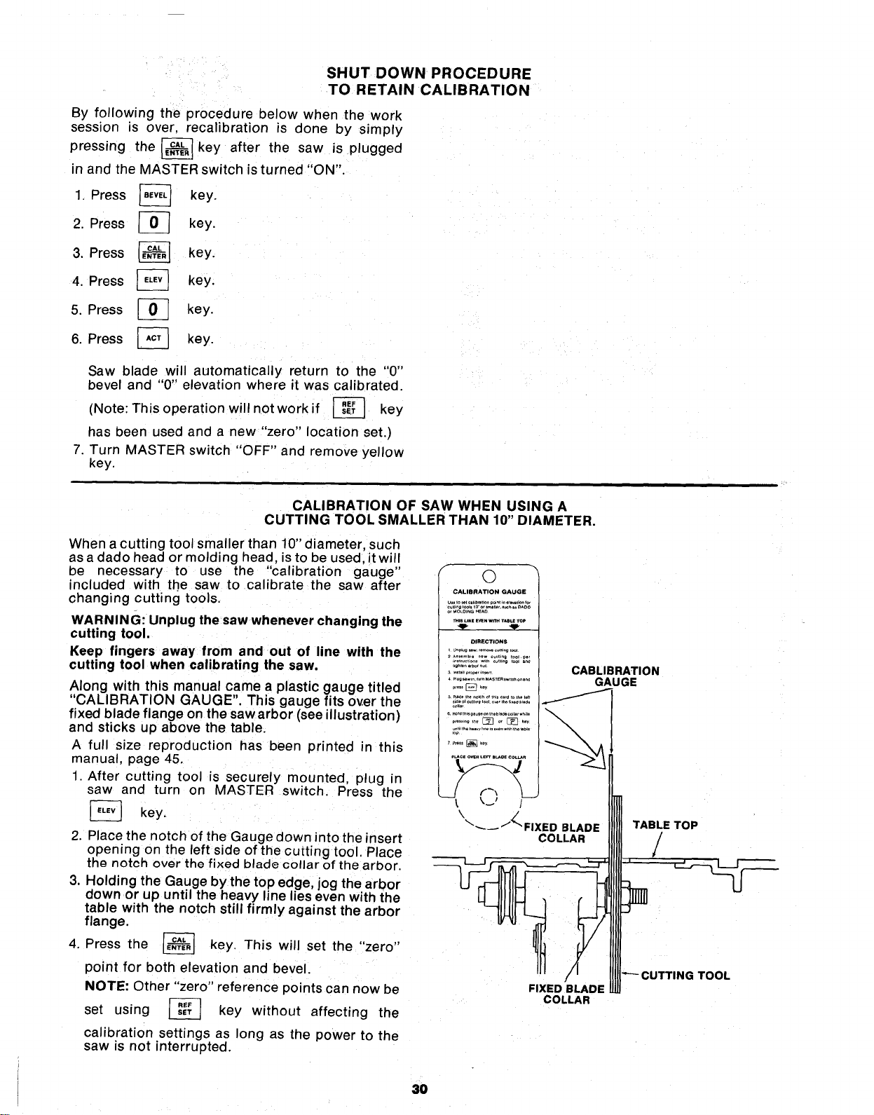
CALIBRATION OF SAW WHEN USING A
CUTTING TOOL SMALLER THAN 10" DIAMETER.
When a cutting tool smaller than 10" diameter, such
as a dado head or molding head, is to be used, it will
be necessary to use the "calibration gauge"
included with the saw to calibrate the saw after
changing cutting tools.
WARNING: Unplug the saw whenever changing the
cutting tool,
Keep fingers away from and out of line with the
cutting tool when calibrating the saw.
Along with this manual came a plastic gauge titled
"CALIBRATION GAUGE". This gauge fits over the
fixed blade flange on the saw arbor (see illustration)
and sticks up above the table.
A full size reproduction has been printed in this
manual, page 45.
1 After cutting tool is securely mounted, plug in
saw and turn on MASTER switch. Press the
[_ key.
2. Place the notch of the Gauge down into the insert
opening on the left side of the cutting tool. Place
the notch over the fixed blade collar of the arbor.
3. Holding the Gauge by the top edge, jog the arbor
down or up until the heavy line lies even with the
table with the notch still firmly against the arbor
flange.
the _ key. This will set the "zero"
4. Press
point for both elevation and bevel.
NOTE: Other "zero" reference points can now be
set using _-_ key without affecting the
calibration settings as long as the power to the
saw is not interrupted.
f
©
CALIBRATION GAUGE
orMO_m_GHEAO
•.;_.......... ,No,
!
FIXED BLADE
COLLAR
CABLIBRATION
GAUGE
TABLE TOP
/
1
TOOL
3O
CROSSCUTTING
CROSSCUTTING is cutting wood across the grain,
at 90° ,or square with both the edge and the flat side
of the wood. This is done with miter gauge setat "0".
The graduations on the miter gauge provide
accuracy for average woodworking. In some cases
where extreme accuracy is required, make a trial cut
and then recheck it with an accurate square, or
protractor.
If necessary, the miter gauge head can be swiveled
slightly to achieve the desired angle.
NOTE: The space between the miter gauge bar and
the groove in the table is held to minimum during
manufacturing.
For maximum accuracy when using the miter
gauge, always "favor" one side of the groove in the
table. In other words, don't move the miter gauge
from side to side while cutting, but keep one side of
the bar riding against one side of the groove.
NOTE: Glue a piece of sandpaper to the face of the
miter gauge head. This will help prevent the
workpiece from "creeping" while it is being cut.
The Hold-Down Clamp (Optional Accessory)
should be used on the miter gauge for greater
accuracy.
The miter gauge may be used in either of the
grooves in the table. Make sure it is locked.
SANDPAPER
When using the miter gauge in the LEFT hand
groove, hold the workpiece firmly against the miter
gauge head with your left hand, and grip the lock
handle with your right.
When using the RIGHT Hand groove, hold the
workpiece with your right hand and the Iockhandle
with your left hand.
In this example a 1" x 6" board will be cut on a 90°
angle to its edge.
NOTE; A 1" thick board is actually 3/4 of an inch
thick.
Have saw calibrated, with tip of blade even with
table top. Have guard in place.
STEP 1- Set the miter gauge to the zero position.
2- Turn MASTER switch on and press
STEP
key. Press number keys _ _
_-_ (the decimal equivalent of
inches). Press _ key. The blade
7/8
will automatically raise to the
programmed height. Blade elevation will
be displayed.
STEP 3- Draw a line on the board at the cut-off
point -- long enough for sighting, position
the board against the miter gauge face.
Align cut-off point with Exact-I-Cut
indicator.
STEP 4- Firmly hold the board in this position. (A
hold down clamp is recommended for
greater accuracy). Turn on the saw motor.
STEP 5 Guide the board through the blade.
STEP 6 Turn the motor "OFF". Wait for the blade
to stop before removing the boards and
returning the miter gauge to the starting
position.
STEP 7- Press _ key. Press number key
Press _. The blade will
lower automatically until isis even with the
table.
WORKPIECE
!
/ [ itI
TABLE
\
31
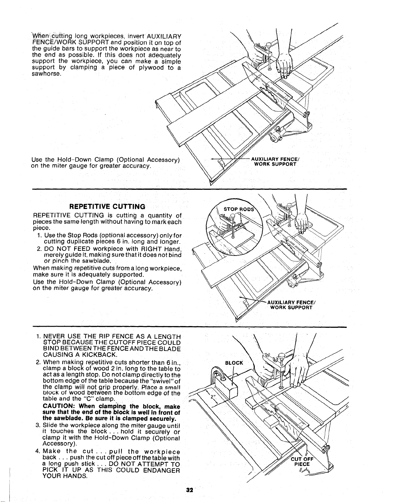
When' cutting long workpieces, invertAUXILIARY
FENCE/WORK SUPPORT and position it on top of
the guide bars to support the workpiece as near to
the end as possible. If this does not adequately
support the workpiece, you can make a simple
support by clamping a piece of plywood to a
sawhorse.
\
\
\
\
/
Use the Hold-Down Clamp (Optional Accessory)
on the miter gauge for greater accuracy.
|Y FENCE/
WORK SUPPORT
REPETITIVE CUTTING
REPETITIVE CUTTING is cutting a quantity of
p!eces the same length without having to mark each
piece.
1, Use the Stop Rods (optional accessory) onlyfor
cutting duplicate pieces 6 in. long and longer.
2. DO NOT FEED workpiece with RIGHT Hand,
merely guide it, making sure that it does not bind
or pinch the sawblade.
When making repetitive cuts from a long workpiece,
make sure it is adequately supported.
Use the Hold-Down Clamp (Optional Accessory)
on the miter gauge for greater accuracy.
WORK SUPPORT
1. NEVER USE THE RIP FENCE AS A LENGTH
STOP BECAUSE THE CUTOFF PIECE COULD
BIND BETWEEN THE FENCE AND THE BLAD E
CAUSING A KICKBACK.
2. When making repetitive cuts shorter than 6 in.,
clamp a block of wood 2 in. long to the table to
act as a length stop. Do not clamp directlyto the
bottom edge of the table because the "swivel" of
the clamp will not grip properly. Place a _mall
block of wood between the bottom edge of the
table and the "C" clamp.
CAUTION: When clamping the block, make
sure that the end of the block is well in front of
the sawblade. Be sure it is clamped securely.
3. Slide the workpiece along the miter gauge until
it touches the block.., hold it securely or
clamp it with the Hold-Down Clamp (Optional
Accessory).
4. Make the cut.., pull the workpiece
back.., push the cut off piece off the table with
a long push stick... DO NOT ATTEMPT TO
PICK IT UP AS THIS COULD ENDANGER
YOUR HANDS.
32
/
/
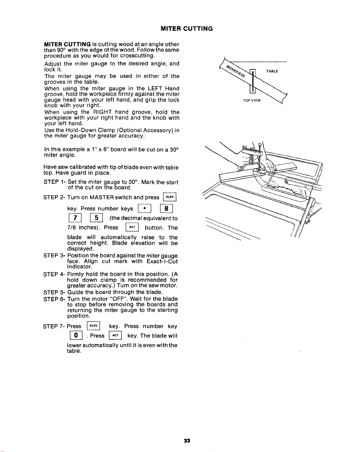
MITER CUTTING
MITER CUTTING is cutting wood at an angle other
than 90° with the edge of the wood. Follow the same
procedure as you would for crosscutting.
Adjust the miter gauge to the desired angle, and
lock it.
The miter gauge may be used in either of the
grooves n the table.
When using the miter gauge in the LEFT Hand
groove, hold the workpiece firmly against the miter
gauge head with your left hand, and grip the lock
knob with your right.
When using the RIGHT hand groove, hold the
workpiece with your right hand and the knob with
your left hand.
Use the Hold-Down Clamp (Optional Accessory) n
the miter gauge for greater accuracy.
In this example a 1" x 6" board will be cut on a 30°
miter angle.
Have saw calibrated withtip of blade even with table
top. Have guard in place.
STEP 1-
STEP 2-
Set the miter gauge to 30°. Mark the start
of the cut on the board.
Turn on MASTER switch and press .[_
key. Press number keys [_
[_ _-_ (the decimal equivalent to
7/8 inches). Press _ button. The
blade will automatically raise to the
correct height. Blade elevation will be
dis played.
STEP 3- Position the board against the miter gauge
face. Align cut mark with Exact-I-Cut
indicator.
STEP 4-
STEP 5-
STEP 6-
STEP 7-
Firmly hold the board in this position. (A
hold down clamp is recommended for
greater accuracy.) Turn on the saw motor.
Guide the board through the blade.
Turn the motor "OFF". Wait for the blade
to stop before removing the boards and
returning the miter gauge to the starting
position.
Press _ key. Press number key
. Press _ key. The blade will
lower automatically until it is even with the
table.
TOP VIEW
TABLE
33
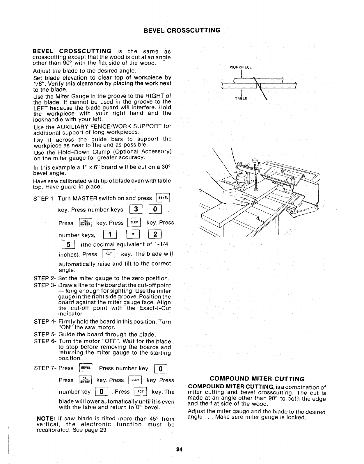
BEVEL CROSSCUTTING
BEVEL CROSSCUTTING is the same as
crosscutting except that the wood is cut at an angle
other than 90° with the flat side of the wood.
Adjust the blade to the desired angle.
Set blade elevation to clear top of workpiece by
1/8". Verify this clearance by placing the work next
to the blade.
Use the Miter Gauge in the groove to the RIGHTof
the blade. It cannot be used in the groove to the
LEFT because the blade guard will interfere. Hold
the workpiece with your right hand and the
Iockhandle with your left.
Use the AUXILIARY FENCE/WORK SUPPORT for
aaditional support of long workpieces.
Lay it across the guide bars to support the
workpiece as near to the end as possible.
Use the Hold-Down Clamp (Optional Accessory)
on the miter gauge for greater accuracy.
In this example a 1" x 6" board will be cut on a 30°
bevel angle.
Have saw calibrated with tip of blade even with table
top. Have guard in place.
STEP 1- Turn MASTER switch on and press
key. Press number keys _ J-_
STEP 2-
STEP 3-
Press _ key. Press _ key. Press
number keys, _ _] _
[_] decimal of 1-1/4
(the equivalent
inches). Press J__ key. The blade
will
automatically raise and tilt to the correct
angle.
Set the miter gauge to the zero position.
Draw a line to the board at the cut-off point
-- long enough for sighting. Use the miter
gauge in the right side groove. Position the
board against the miter gauge face Align
the cut-off point with the Exact-I-Cut
indicator.
STEP 4-
STEP5-
STEP6-
STEP7-
Firmly hold the board in this position. Turn
'ON" the saw motor.
Guide the board through the blade.
Turn the motor "OFF". Wait for the blade
to stop before removing the boards and
returning the miter gauge to the starting
po_ition.
. Press number key _ .
Press
Press _ key. Press _ key. Press
numberkey _ , Press J-_ key, The
blade will lower automatically until it is even
with the table and return to 0° bevel.
NOTE: If saw blade is tilted more than 45 ° from
vertical, the electronic function must be
recalibrated. See page 29.
WORKPIECE
TABLE
\
\
\\\
\
\
\
COMPOUND MITER CUTTING
COMPOUND MITER CUTTING, isa combination of
miter cutting and bevel crosscutting. The cut is
made at an angle other than 90° to both the edge
and the flat side of the wood.
Adjust the miter gauge and the blade to the desired
angle... Make sure miter gauge is locked.
34
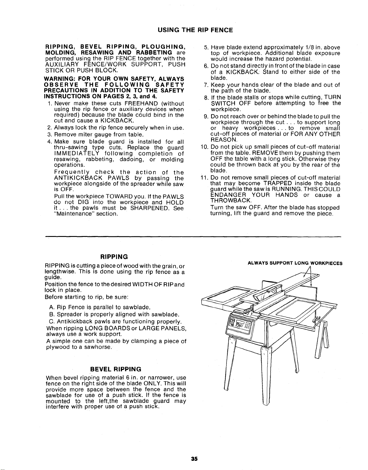
USING THE RIP FENCE
RIPPING, BEVEL RIPPING, PLOUGHING,
MOLDING, RESAWING AND RABBETING are
performed using the RIP FENCE together with the
AUXILIARY FENCE/WORK SUPPORT, PUSH
STICK OR PUSH BLOCK.
WARNING: FOR YOUR OWN SAFETY, ALWAYS
OBSERVE THE FOLLOWING SAFETY
PRECAUTIONS IN ADDITION TO THE SAFETY
INSTRUCTIONS ON PAGES 2, 3, and 4.
1. Never make these cuts FREEHAND (without
using the rip fence or auxiliary devices when
required) because the blade could bind in the
cut and cause a KICKBACK.
2. Always lock the rip fence securely when in use.
3_ Remove miter gauge from table.
4. Make sure blade guard is installed for all
thru-sawing type cuts. Replace the guard
IMMEDIATELY following completion of
resawing, rabbeting, dadoing, or molding
operations.
Frequently check the action of the
ANTIKICKBACK PAWLS by passing the
workpiece alongside of the spreader while saw
is OFF.
Pull the workpiece TOWARD you. If the PAWLS
do not DIG into the workpiece and HOLD
it... the pawls must be SHARPENED. See
"Maintenance" section.
5. Have blade extend approximately 1/8 in. above
top of workpiece. Additional blade exposure
would increase the hazard potential.
6. Do not stand directly in front of the blade in case
of a KICKBACK. Stand to either side of the
blade.
7. Keep your hands clear of the blade and out of
the path of the blade.
8. If the blade stalls or stops while cutting, TURN
SWITCH OFF before attempting to free the
workpiece.
9. Do not reach over or behind the blade to pull the
workpiece through the cut.., to support long
or heavy workpieces.., to remove small
cut-off pieces of material or FOR ANY OTHER
REASON.
10. Do not pick up small pieces of cut-off material
from the table. REMOVE them by pushing them
OFF the table with a long stick. Otherwise they
could be thrown back at you by the rear of the
blade.
il. Do not remove small pieces of cut-off material
that may become TRAPPED inside the blade
guard while the saw is RUNNING. THIS COULD
ENDANGER YOUR HANDS or cause a
THROWBACK.
Turn the saw OFF. After the blade has stopped
turning, lift the guard and remove the piece.
RIPPING
RIPPING is cutting a piece of wood with the grain, or
lengthwise. This is done using the rip fence as a
guide.
Position the fence to the desired WIDTH OF RIPand
lock in place.
Before starting to rip, be sure:
A. Rip Fence is parallel to sawblade.
B. Spreader is properly aligned with sawblade.
C. Antikickback pawls are functioning properly.
When ripping LONG BOARDS or LARGE PANELS,
always use a work support.
A simple one can be made by clamping a piece of
plywood to a sawhorse.
BEVEL RIPPING
When bevel ripping materia-I 6 in. or narrower, use
fence on the right side of the blade ONLY. This will
provide more space between the fence and the
sawblade for use of a push stick. If the fence is
mounted to the left,the sawblade guard may
interfere with proper use of a push stick.
ALWAYS SUPPORT LONG WORKPIECES
35
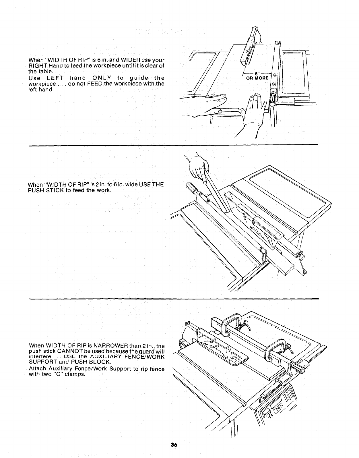
When "WIDTH OF RIP" is 6 in. and WIDER use your
RIGHT Hand to feed the workpiece until it isclear of
the table.
Use LEFT hand ONLY to guide the
workpiece.., do not FEED the workpiece with,the
left hand.
OR MORE
When "WIDTH OF RIP" is 2in. to 6in. wide USE THE
PUSH STICK to feed the work.
When WIDTH OF RIP is NARROWER than 2 in., the
push stick CANNOT be used because the guard will
interfere... USE the AUXILIARY FENCE/WORK
SUPPORT and PUSH BLOCK.
Attach Auxiliary Fence/Work Support to rip fence
with two "C" clamps.
36
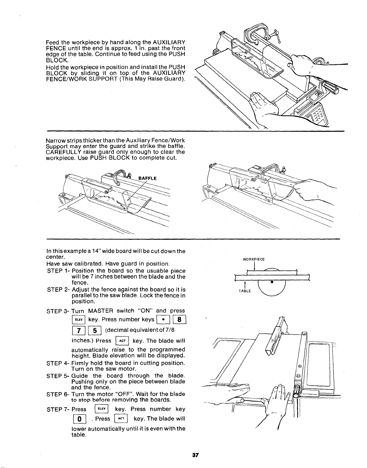
FeedtheworkpiecebyhandalongtheAUXILIARY
FENCEuntiltheendisapprox.1in.pastthefront
edgeofthetable.ContinuetofeedusingthePUSH
BLOCK.
HoldtheworkpieceinpositionandinstallthePUSH
BLOCKby sliding it on top of the AUXILIARY
FENCE/WORKSUPPORT(ThisMayRaiseGuard).
NarrowstripsthickerthantheAuxiliaryFence/Work
Supportmayentertheguardandstrikethebaffle.
CAREFULLYraiseguardonlyenoughto clearthe
workpiece.UsePUSHBLOCKto completecut.
BAFFLE
In this example a 14" wide board will be cut down the
center.
Have saw calibrated. Have guard in position.
STEP 1- Position the board so the usuable piece
will be 7 inches between the blade and the
fence.
STEP 2- Adjust the fence against the board so it is
parallel to the saw blade. Lock the fence in
position,
STEP 3-
STEP 4-
STEP 5-
STEP 6-
STEP 7-
Turn MASTER switch "ON" and press
•_ key. Press number keys _
_-_ (decimal equivalent of 7/8
inches.) Press [_ key. The blade will
automatically raise to the programmed
height. Blade elevation will be displayed.
Firmly hold the board in cutting position.
Turn on the saw motor.
Guide the board through the blade,
Pushing only on the piece between blade
and the fence.
Turn the motor "OFF". Wait for the blade
to _top before removing the boards.
Press _ key. Press number key
[_ , Press _ key. The blade will
lower automatically until it is even with the
table.
WORKPIECE
37
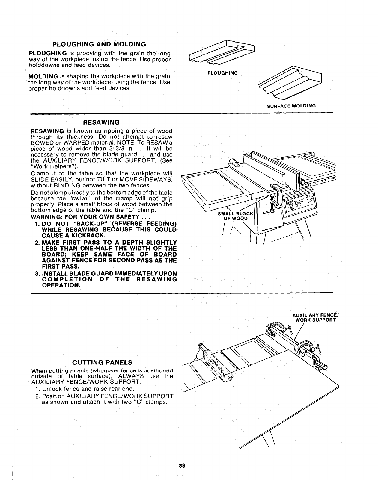
PLOUGHINGAND MOLDING
PLOUGHINGisgrooving with the grain the long
way of the workplece using the fence Use proper
holddowns and feed devices.
MOLDING is shaping the workpiece with the grain
the long way of the workpiece, using the fence. Use
proper holddowns and feed devices
PLOUGHING
SURFACE MOLDING
RESAWING
RESAWING is known as ripping a piece of wood
through its thickness. Do not attempt to resaw
BOWED or WARPED material. NOTE: To RESAWa
piece of wood wider than 3-3/8 in,. . it will be
necessary to remove the blade guard.., and use
the AUXILIARY FENCE/WORK SUPPORT. (See
"Work Helpers' ).
Clamp it to the table so that the workpiece will
SLIDE EASILY, but not TILT or MOVE SIDEWAYS,
without BINDING between the two fences.
Do not clamp directly to the bottom edge of the table
because the "swivel" of the clamp will not grip
properly. Place a small block of wood between the
bottom edge of the table and th_ "C" clamp.
WARNING: FOR YOUR OWN SAFETY...
1. DO NOT "BACK-UP" (REVERSE FEEDING)
WHILE RESAWING BECAUSE THIS COULD
CAUSE A KICKBACK.
2. MAKE FIRST PASS TO A DEPTH SLIGHTLY
LESS THAN ONE-HALF THE WIDTH OF THE
BOARD; KEEP SAME FACE OF BOARD
AGAINST FENCE FOR SECOND PASS AS THE
FIRST PASS.
3. INSTALL BLADE GUARD IMMEDIATELY UPON
COMPLETION OF THE RESAWING
OPERATION.
SMALL BLOCK
OF WOOD
//',, \
CUTTING PANELS
When cutting panels (whenever fenoe is positioned
outside of table surface), ALWAYS
AUXILIARY FENCE/WORK SUPPORT.
1. Unlock fence and raise rear end
2. Position AUXILIARY FENCE/WORK SUPPORT
as shown and attach it with two "C" clamps.
AUXILIARY FENCE/
__ yRK SUPPORT
use the __
38
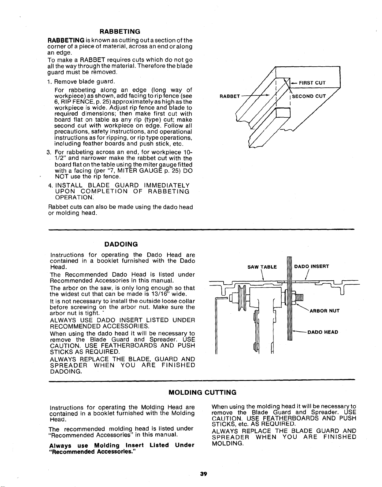
RABBETING
RABBETINGis known as cutting out a section of the
corner of a piece of material, across an end or along
an edge.
To make a RABBET requires cuts which do not go
all the way through the material. Therefore the blade
guard must be removed.
1. Remove blade guard.
For rabbeting along an edge (long way of
workpiece) as shown, add facing to rip fence (see
6, RIP FENCE, p. 25) approximately as high as the
workpiece is wide. Adjust rip fence and blade to
required dimensions; then make first cut with
board flat on table as any rip (type) cut; make
second cut with workpiece on edge. Follow all
precautions, safety instructions, and operational
instructions as for ripping, or rip type operations,
including feather boards and push stick, etc.
3. For rabbeting across an end, for workpiece 10-
1/2" and narrower make the rabbet cut with the
board flat on the table using the miter gauge fitted
with a facing (per "7, MITER GAUGE p. 25) DO
NOT use the rip fence.
4. INSTALL BLADE GUARD IMMEDIATELY
UPON COMPLETION OF RABBETING
OPERATION.
Rabbet cuts can also be made using the dado head
or molding head.
RABBET
FIRST CUT
DADOING
Instructions for operating the Dado Head are
contained in a booklet furnished with the Dado
Head.
The Recommended Dado Head is listed under
Recommended Accessories in this manual.
The arbor on the saw, is only long enough so that
the widest cut that can be made is 13/16" wide.
It is not necessary to install the outside loose collar
before screwing on the arbor nut. Make sure the
arbor nut is tight. "
ALWAYS USE DADO INSERT LISTED UNDER
RECOMMENDED ACCESSORIES.
When using the dado head it will be necessary to
remove the Blade Guard and Spreader. USE
CAUTION. USE FEATHERBOARDS AND PUSH
STICKS AS REQUIRED.
ALWAYS REPLACE THE BLADE, GUARD AND
SPREADER WHEN YOU ARE FINISHED
DADOING.
SAW TABLE
\
DADO INSERT
/
HEAD
MOLDING CUTTING
Instructions for operating the Molding Head are
contained in a booklet furnished with the Molding
Head.
The recommended molding head is listed under
"Recommended Accessories" in this manual.
Always use Molding Insert Listed Under
"Recommended Accessories."
When using the molding head it will be necessary to
remove the Blade Guard and Spreader. USE
CAUTION. USE FEATHERBOARDS AND PUSH
STICKS, etc. AS REQUIRED.
ALWAYS REPLACE THE BLADE GUARD AND
SPREADER WHEN YOU ARE FINISHED
MOLDING.
39
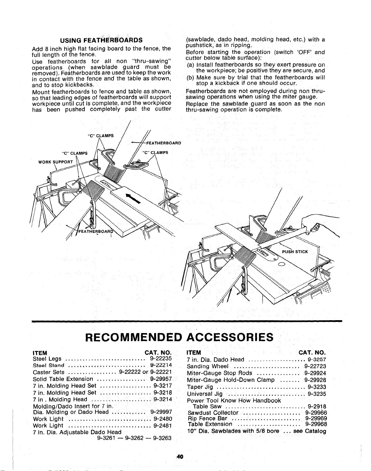
USING FEATHERBOARDS
Add 8 inch high flat facing board to the fence, the
full length of the fence.
Use featherboards for all non "thru-sawing"
operations (when sawblade guard must be
removed). Featherboards are used to keep the work
in contact with the fence and the table as shown,
and to stop kickbacks.
Mount featherboards to fence and table as shown,
so that leading edges of featherboards will support
workpiece until cut is complete, and the workp_ece
has been pushed completely past the cutter
/
/
_BOARD
"C" CLAMPS
WORK SUPPORT
(sawblade, dado head, molding head, etc.) with a
pushstick, as in ripping.
Before starting the operation (switch 'OFF' and
cutter below table surface}:
(a) Install featherboards so they exert pressure on
the workpiece; be positive they are secure, and
(b) Make sure by trial that the featherboards will
stop a kickback if one should occur.
Featherboards are not employed during non thru-
sawing operations when using the miter gauge
Replace the sawblade guard as soon as the non
thru-sawing operation is complete.
/
/
RECOMMENDED ACCESSORIES
ITEM CAT. NO.
Steel Legs ............................ 9-22235
_t_gl _tand ........................... 9-22214
Caster Sets ................. 9-22222 or 9-22221
Solid Table Extension ................. 9-29957
7 in. Molding Head Set .................. 9-3217
7 in. Molding Head Set .................. 9-3218
7 in. Molding Head ..................... 9-3214
Molding/Dado Insert for 7 in.
Dia. Molding or Dado Head ............ 9-29997
Work Light ............................. 9-2480
Work Light ............................. 9-2481
7 in. Dia. Adjustable Dado Head
9-3261 -- 9-3262 -- 9-3263
ITEM CAT. NO.
7 in. Dia. Dado Head .................... 9-3257
Sanding Wheel ....................... 9-22723
Miter-Gauge Stop Rods ............... 9-29924
Miter-Gauge Hold-Down Clamp ....... 9-29928
Taper Jig ............................... 9-3233
Universal Jig ........................... 9-3235
Power Tool Know HOW Handbook
Table Saw ............................ 9-2918
Sawdust Collector .................... 9-29966
Rip Fence Bar ........................ 9-29969
Table Extension ...................... 9-29968
10" Dia. Sawblades with 5/8 bore ... see Catalog
4O
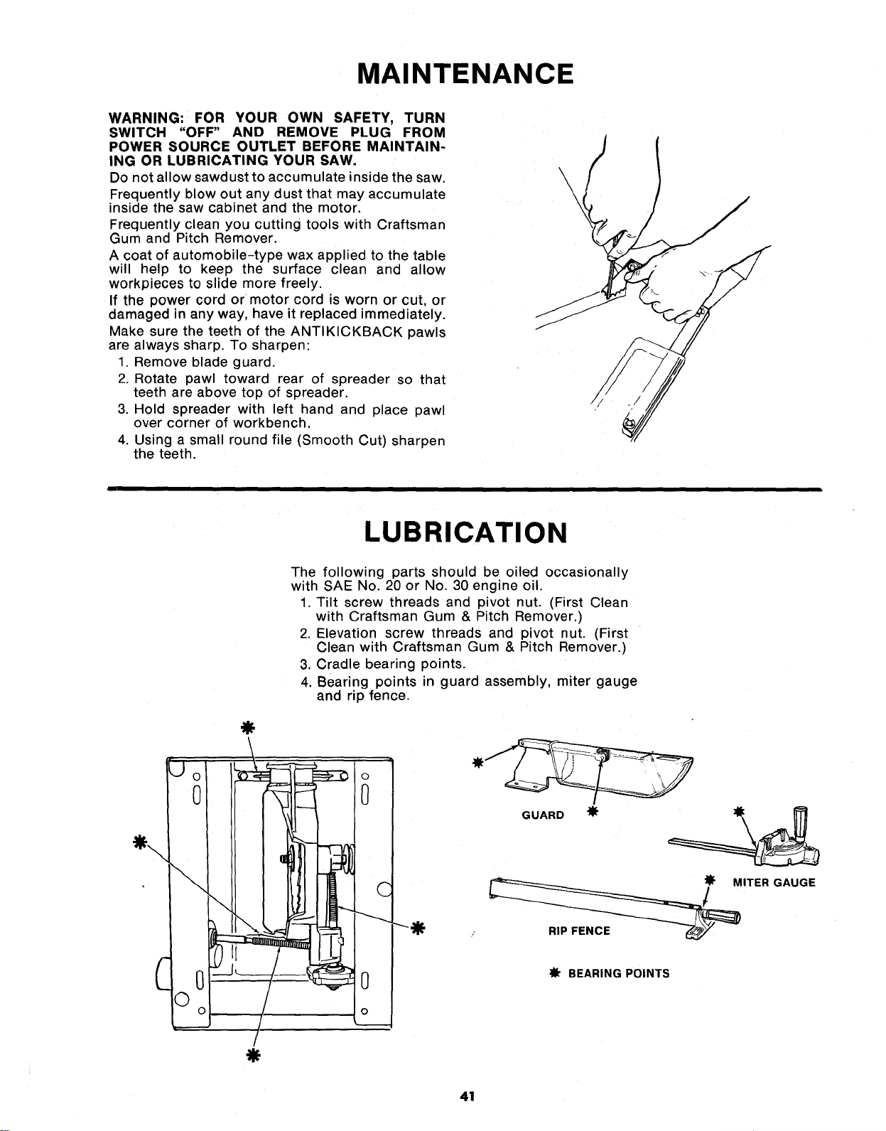
MAINTENANCE
WARNING: FOR YOUR OWN SAFETY, TURN
SWITCH "OFF" AND REMOVE PLUG FROM
POWER SOURCE OUTLET BEFORE MAINTAIN-
ING OR LUBRICATING YOUR SAW,
Do not allow sawdust to accumulate inside the saw.
Frequently blow out any dust that may accumulate
inside the saw cabinet and the motor.
Frequently clean you cutting tools with Craftsman
Gum and Pitch Remover.
A coat of automobile-type wax applied to the table
will help to keep the surface clean and allow
workpieces to slide more freely.
If the power cord or motor cord is worn or cut, or
damaged in any way, have it replaced immediately.
Make sure the teeth of the ANTIKICKBACK pawls
are always sharp. To sharpen:
1. Remove blade guard.
2. Rotate pawl toward rear of spreader so that
teeth are above top of spreader.
3. Hold spreader with left hand and place pawl
over corner of workbench.
4. Using a small round file (Smooth Cut) sharpen
the teeth.
\
\
\
LUBRICATION
0
\
0
©o
The following parts should be oiled occasionally
with SAE No. 20 or No. 30 engine oil.
1. Tilt screw threads and pivot nut. (First Clean
with Craftsman Gum & Pitch Remover.)
2. Elevation screw threads and pivot nut. (First
Clean with Craftsman Gum & Pitch Remover.)
3. Cradle bearing points.
4. Bearing points in guard assembly, miter gauge
and rip fence.
\! :. ...
©
0
C
0
o
---O
GUARD
ITER GAUGE
_fr BEARING POINTS
41
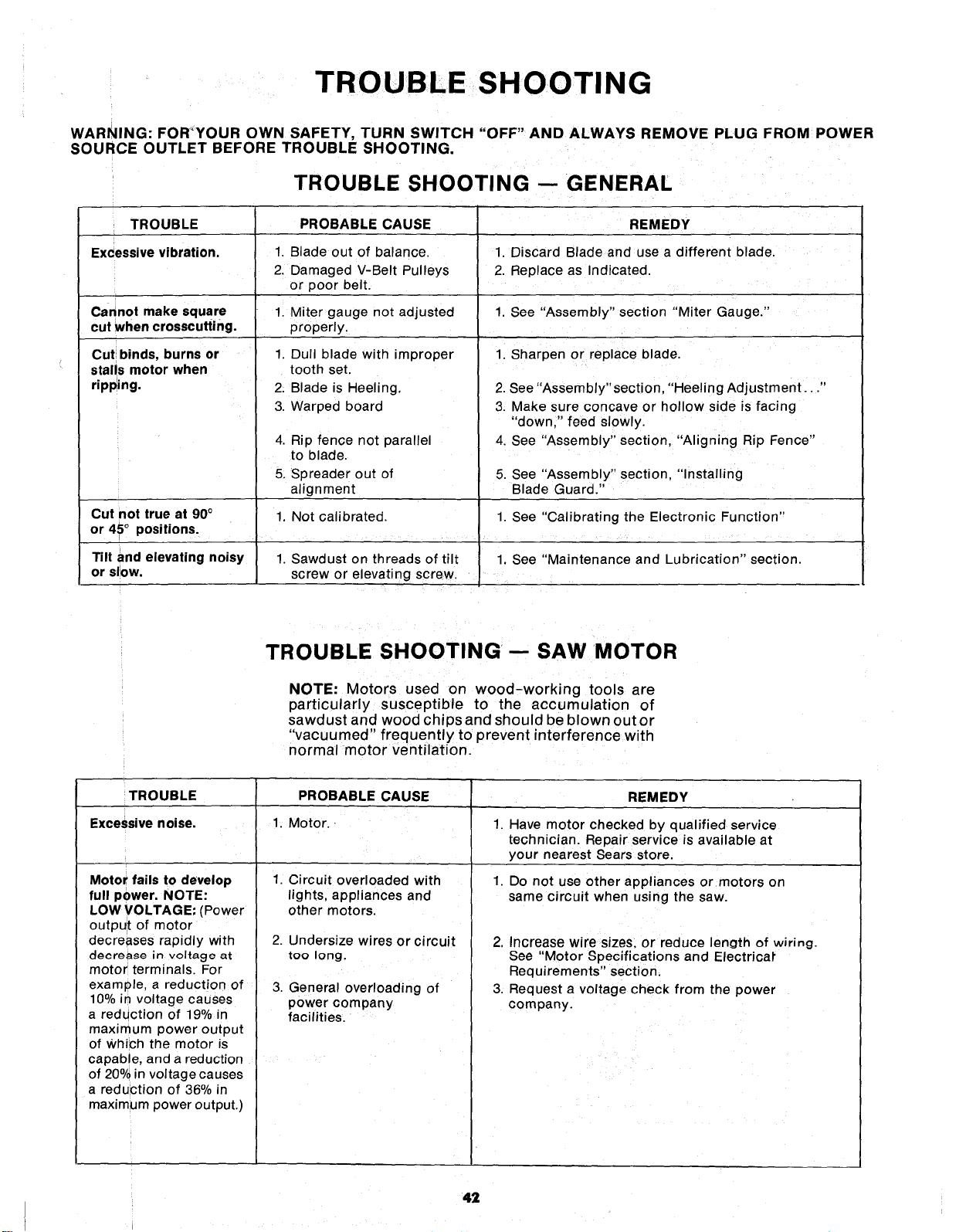
TROUBLESHOOTING
WARNING: FOR'YOUR OWN SAFETY, TURN SWITCH "OFF" AND ALWAYS REMOVE PLUG FROM POWER
SOURCE OUTLET BEFORE TROUBLE SHOOTING,
TROUBLE SHOOTING -- GENERAL
TROUBLE
Excessive vibration,
PROBABLE CAUSE
Cannot make square
cut when crosscutting.
Cut binds, burns or
stalls motor when
ripping.
Cut not true at 90°
or 45° positions.
Tilt and elevating noisy
or slow.
1. Blade out of balance.
2. Damaged V-Belt Pulleys
or poor belt.
1. Miter gauge not adjusted
properly.
1. Dull blade with improper
tooth set.
2. Blade is Heeling,
3. Warped board
4. Rip fence not parallel
to blade.
5, Spreader out of
alignment
1, Not calibrated.
1. Sawdust on threads of tilt
screw or elevating screw.
REMEDY
1. Discard Blade and use a different blade.
2. Replace as Indicated.
1. See "Assembly" section "Miter Gauge."
1. Sharpen or replace blade.
2. See "Assembly"section, "Heeling Adjustment..."
3. Make sure concave or hollow side is facing
"down," feed slowly.
4. See "Assembly" section, "Aligning Rip Fence"
5. See "Assembly" section, "Installing
Blade Guard."
1. See "Calibrating the Electronic Function"
1. See "Maintenance and Lubrication" section.
TROUBLE SHOOTING-- SAW MOTOR
NOTE: Motors used on wood-working tools are
particularly susceptible to the accumulation of
sawdust and wood chips and should be blown outor
"vacuumed" frequently to prevent interference with
normal motor ventilation.
TROUBLE PROBABLE CAUSE REMEDY
Excessive noise. 1, Motor. 1. Have motor checked by qualified service
technician. Repair service is available at
your nearest Sears store.
1.Motor fails to develop
full power. NOTE:
LOW VOLTAGE: (Power
output of motor
decreases rapidly with
dgere_e in voltage at
motor terminals. For
example, a reduction of
10% in voltage causes
a reduction of 19% in
maximum power output
of Which the motor is
capable, and a reduction
of 20% in voltage causes
a reduction of 36% in
maximum power output.)
1. Circuit overloaded with
lights, appliances and
other motors.
2. Undersize wires or circuit
too long.
3.
General overloading of
power company
facilities.
Do not use other appliances or motors on
same circuit when using the saw.
2. Increase wire sizes, or reduce Igngth of wiring.
See "Motor Specifications and Electrical"
Requirements" section.
3. Request a voltage check from the power
company.
42
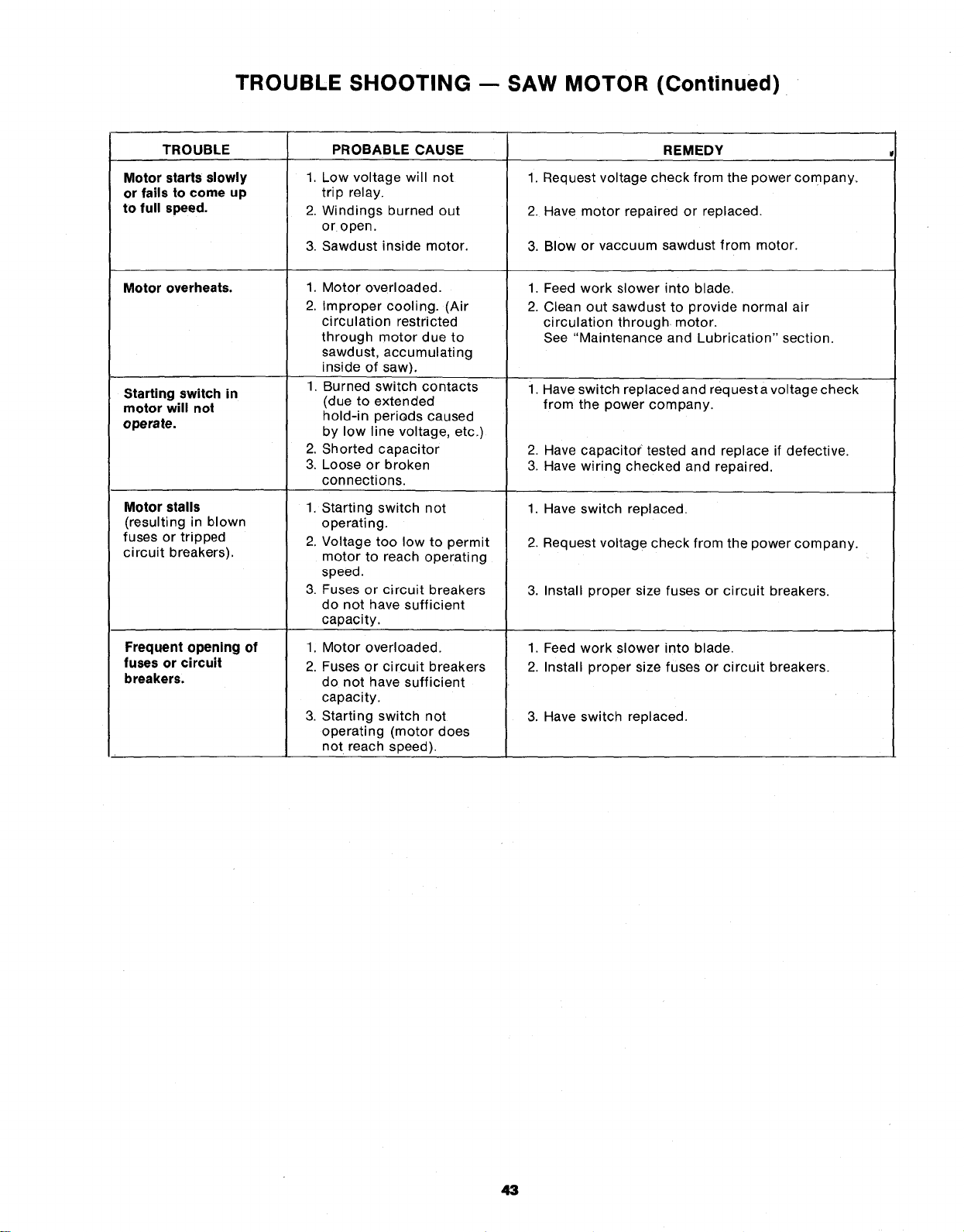
TROUBLE SHOOTING -- SAW MOTOR (Continued)
TROUBLE PROBABLE CAUSE
Motor starts slowly
or fails to come up
to full speed.
Motor overheats.
Starting switch in
motor will not
operate.
Motor stalls
(resulting in blown
fuses or tripped
circuit breakers).
Frequent opening of
fuses or circuit
breakers,
1. Low voltage will not
trip relay.
2. Windings burned out
or open.
3. Sawdust inside motor.
1. Motor overloaded.
2. Improper cooling. (Air
ci rculation restricted
through motor due to
sawdust, accumulating
inside of saw).
1, Burned switch contacts
(due to extended
hold-in periods caused
by low line voltage, etc.)
2. Shorted capacitor
3, Loose or broken
connections.
1. Starting switch not
operating.
2. Voltage too low to permit
motor to reach operating
speed.
3. Fuses or circuit breakers
do not have sufficient
capacity.
1; Motor overloaded.
2. Fuses or circuit breakers
do not have sufficient
capacity.
3. Starting switch not
operating (motor does
not reach speed).
REMEDY
1. Request voltage check from the power company.
2. Have motor repaired or replaced.
3. Blow or vaccuum sawdust from motor.
1,
2.
Feed work slower into blade.
Clean out sawdust to provide normal air
circulation through motor.
See "Maintenance and Lubrication" section.
1. Have switch replaced and request avoltage check
from the power company.
2. Have capacito( tested and replace if defective.
3. Have wiring checked and repaired.
1. Have switch replaced.
2. Request voltag e check from the power company.
3. Install proper size fuses or circuit breakers.
1. Feed work slower into blade.
2. Install proper size fuses or circuit breakers.
3. Have switch replaced.
43
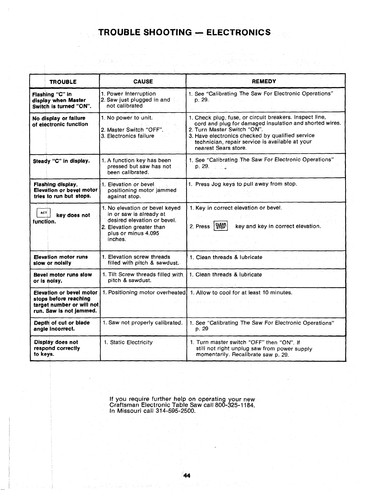
TROUBLE SHOOTING -- ELECTRONICS
TROUBLE
Flashing "C" in
display when Master
Switch is turned "ON".
No display or failure
of electronic function
CAUSE
i
1. Power Interruption
2. Saw just plugged in and
not calibrated
1. No power to unit.
2. Master Switch "OFF".
3. Electronics failure
1. A function key has been
pressed but saw has not
been calibrated.
1. Elevation or bevel 1.
positioning motor jammed
against stop.
1. No elevation or bevel keyed
in or saw is already at
desired elevation or bevel.
2. Elevation greater than
plus or minus 4.095
inches.
1. Elevation screw threads
filled with pitch & sawdust.
1. Tilt Screw threads filled .with.
pitch & sawdust.
1. Positioning motor overheated,
1. Saw not properly calibrated.
1. Static Electricity
Steady "C" in display.
Flashing display.
Elevation or bevel motor
tries to run but stops.
key does not
function.
Elevation motor runs
slow or noisily
Bevel motor runs slow
or is noisy.
Elevation or bevel motor
stops before reaching
target number or will not
run. Saw is not jammed.
Depth of cut or blade
angle incorrect.
Display does not
respond correctly
to keys.
REMEDY
1. See Cahbrating The Saw For Electronic Operations"
p. 29.
1. Check plug, fuse, or circuit breakers. Inspect line,
cord and plug for damaged insulation and shorted wires.
2. Turn Master Switch "ON".
3. Have electronics checked by qualified service
technician, repair service is available at your
nearest Sears store.
1. See "Calibrating The Saw For Electronic Operations"
p. 29. _
Press Jog keys to pull away from stop.
1. Key in correct elevation or bevel.
2. Press _ key and key in correct elevation.
1. Clean threads & lubricate
1. Clean threads & lubricate
1. Allow to cool for at least 10 minutes.
1. See "Calibrating The Saw For Electronic Operations"
p. 29
1. Turn master switch "OFF" then "ON". If
still not right unplug saw from power supply
momentarily. Recalibrate saw p, 29.
If you require further help on operating your new
Craftsman Electronic Table Saw call 800-325-1184.
In Missouri call 314-595-2500.
44
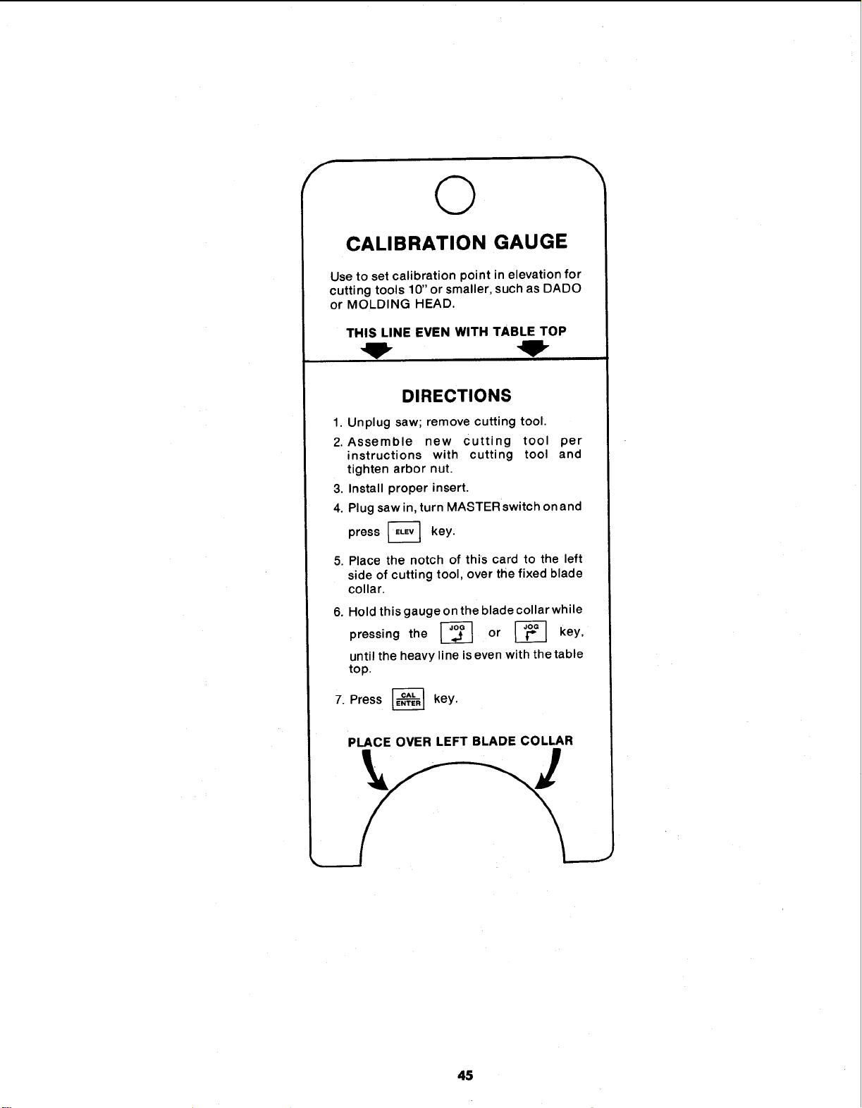
f
©
CALIBRATION GAUGE
Use to set calibration point in elevation for
cutting tools 10" or smaller, such as DADO
or MOLDING HEAD.
THIS LINE EVEN WITH TABLE TOP
DIRECTIONS
1. Unplug saw; remove cutting tool.
2. Assemble new Cutting tool per
instructions with cutting tool and
tighten arbor nut.
3, Install proper insert.
4. Plug saw in, turn MASTER switch on and
press _ key.
5. Place the notch of this card to the left
side of cutting tool, over the fixed blade
collar.
6.
7.
Hold this gauge on the blade collar while
pressing the _ or _ key,
until the heavy line is even with the table
top.
Press _ key.
PLACE OVER LEFT BLADE COLLAR
45
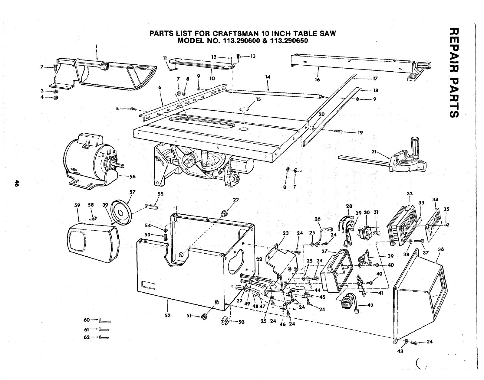
1
PARTS LIST FOR CRAFTSMAN 10 INCH TABLE SAW
MODEL NO. 113.290600 & 113.290650
,15
/
14
m
"o
I
'!1
1>
-4
59 58 39
60 _
61_
62 _
o
o
57 55
/ 22
19
I
I
28
[ 29 30 31
32
34
33
35
<
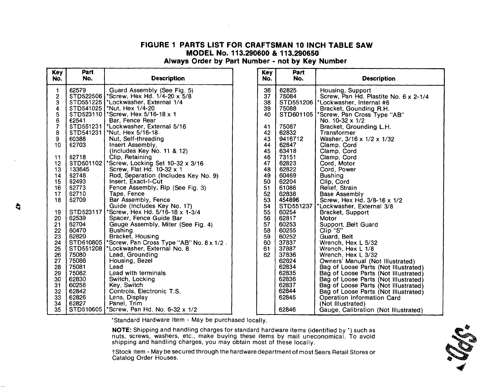
FIGURE 1 PARTS LIST FOR CRAFTSMAN 10 INCH TABLE SAW
MODEL No. 113.290600 & 113,290650
Always Order by Part Number - not by Key Number
Key Part
No. No. Description
1 62579
2 STD522506
3 STD551225
4 STD541025
5 STD523110
6 62541
7 STD551231
8 STD541231
9 60388
10 62703
11 62718
12 STD501102
13 133645
14 62748
15 62493
16 62773
17 62710
18 82709
19 STD5231!7
20 62539
21 82704
22 60470
23 62820
24 STD610805
25 STD551208
26 75080
27 75086
28 75081
29 75082
30 62830
31 60256
32 62842
33 62826
34 62827
35 STD510605
Guard Assembly (See Fig. 5)
*Screw, Hex Hd. 1/4-20 x 5/8
*Lockwasher, External 1/4
*Nut, Hex 1/4-20
*Screw, Hex 5/16-18 x 1
Bar, Fence Rear
*Lockwasher, External 5/16
*Nut, Hex 5/16-18-
Nut, Self-threading
Insert Assembly,
(Includes Key No. 11 & 12)
Clip, Retaining
*Screw, Locking Set 10-32 x 3/16
Screw, Flat Hd. 10-32 x 1
Rod, Separation (Includes Key No. 9)
Insert, Exact-I-Cut
Fence Assembly, Rip (See Fig. 3)
Tape, Fence
Bar Assembly, Fence
Guide (Includes Key No. 17)
*Screw, Hex Hd. 5/16-18 x 1-3/4
Spacer, Fence Guide Bar
Gauge Assembly, Miter (See Fig. 4)
Bushing
Bracket, Housing
*Screw, Pan Cross Type "AB" No. 8 x 1/2
*Lockwasher, External No. 8
Lead, Grounding
Housing, Bezel
Lead
Lead with terminals
Switch, Locking
Key, Switch
Controls, Electronic T.S.
Lens, Display
Panel, Trim
*Screw, Pan Hd. No. 6-32 x 1/2
*Standard Hardware Item - May be purchased locally.
Key Part
No. No. Description
36
37
38
39
40
62825
75084
STD551206
75088
STD601105
41 75087
42 62832
43 9416712
44 62847
45 63418
46 73151
47 62823
48 62822
49 60469
50 62204
51 61086
52 62838
53 454896
54 STD551237
55 60254
56 62817
57 60253
58 60255
59 60252
60 37837
61 37887
62 37836
62824
62834
62835
62836
62837
62844
62845
62846
Housing, Support
Screw, Pan Hd. Plastite No. 6 x 2-1/4
*Lockwasher, Internal #6
Bracket, Gounding R.H.
*Screw, Pan Cross Type "AB"
No. 10-32 x 1/2
Bracket, Grounding L.H.
Transformer
Washer, 3/16 x 1/2 x 1/32
Clamp, Cord
Clamp, Cord
Clamp, Cord
Cord, Motor
Cord, Power
Bushing
Clip, Cord
Relief, Strain
Base Assembly
Screw, Hex Hd. 3/8-16 x 1/2
*Lockwasher, External 3/8
Bracket, Support
Motor
Support, .Belt Guard
Clip "S"
Guard, Belt
Wrench, Hex L 5/32
Wrench, Hex L 1/8
Wrench, Hex L 3/32
Owners' Manual (Not Illustrated)
Bag of Loose Parts (Not Illustrated)
Bag of Loose Parts (Not Illustrated)
Bag of Loose Parts (Not Illustrated)
Bag of Loose Parts (Not Illustrated)
Bag of Loose Parts (Not Illustrated)
Operation Information Card
(Not Illustrated)
Gauge, Calibration (Not Illustrated)
NOTE: Shipping and handling charges for standard hardware items (identified by *) such as
nuts, screws, washers, etc, make buying these items by mail uneconomical. To avoid
shipping andhandling charges, you may obtain most of these locally.
_-Stock Item - May be secured through the hardware department of most Sears Retail Stores or
Catalog Order Houses.
,#
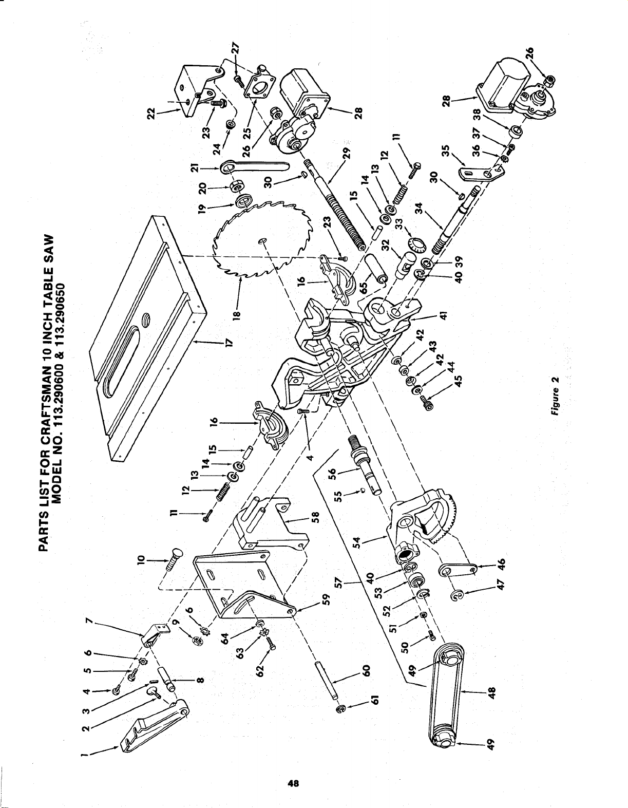
I
0
Z,,..
m,im
i! o
0
_d
ii. I11
I-Q
_0
m
II
/
\
0
\
i
\
\
P_
48

€
O
12.
u)
mo
Z,'-
5
q..
(_ c0
O0
x _ x
• i
o: _ _ _
Z _ _ _ x._J "o
_ _" _o _ -
_:_x
.-- _X 0
', .E :E ,,_co,_ . ,-n
t--
E
o.
o
°,__ r
_0
>,_0
'£ , ,_
P
49
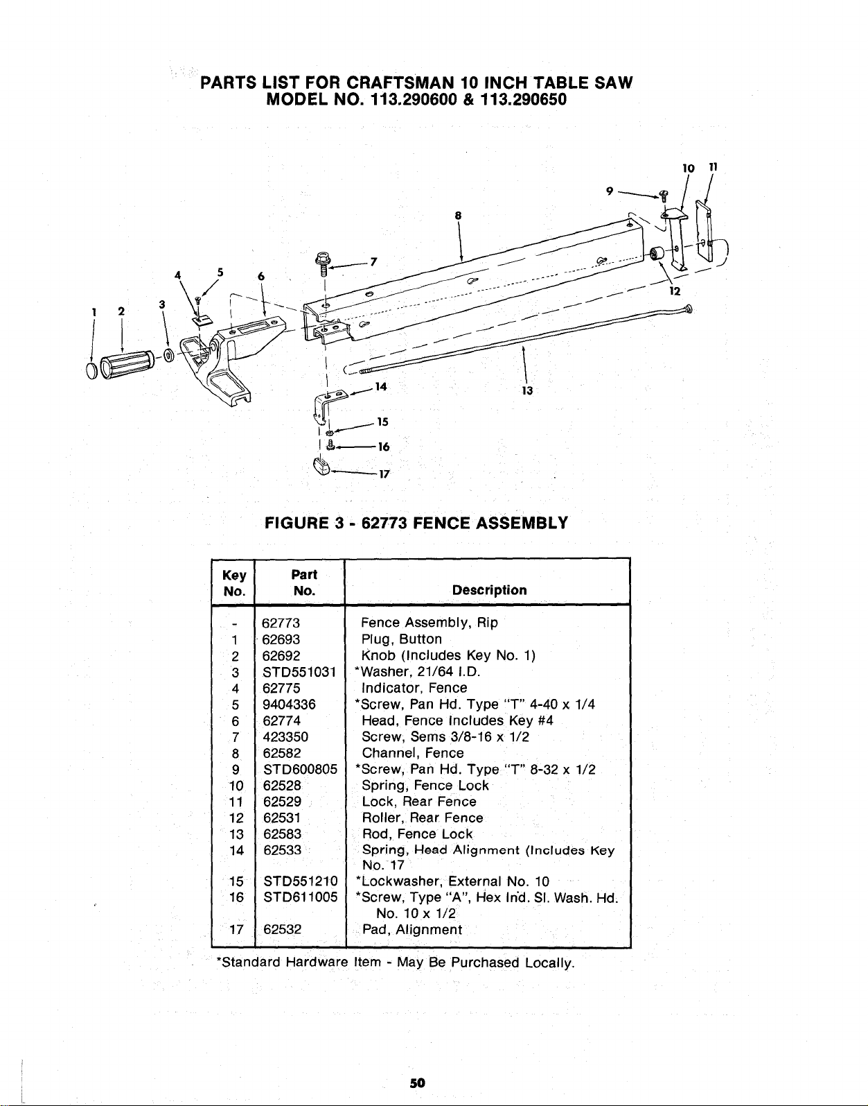
PARTS LIST FOR CRAFTSMAN 10 INCH TABLE SAW
MODEL NO. 113.290600 & 113.290650
10 11
, = \L ',
.__1415 13
t& 16
_)'*'-'-"-'- 17
FIGURE 3 - 62773 FENCE ASSEMBLY
Key Part
No. No. Description
62773
1 62693
2 62692
3 STD551031
4 62775
5 9404336
6 62774
7 423350
8 62582
9 STD600805
10 62528
11 62529
12 62531
13 62583
14 62533
15 STD551210
16 STD611005
17 62532
Fence Assembly, Rip
Plug, Button
Knob (Includes Key No. 1)
*Washer, 21/64 I.D.
Indicator, Fence
*Screw, Pan Hd. Type "T" 4-40 x 1/4
Head, Fence Includes Key #4
Screw, Sems 3/8-16 x 1/2
Channel, Fence
*Screw, Pan Hd. Type "T" 8-32 x 1/2
Spring, Fence Lock
Lock, Rear Fence
Roller, Rear Fence
Rod, Fence Lock
gpring, Head Alignment (Include8 Key
No. 17
*Lockwasher, External No. 10
*Screw, Type "A", Hex Ind. SI. Wash. Hd.
No. 10 x 1/2
Pad, Alignment
i
*Standard Hardware Item - May Be Purchased Locally.
5O
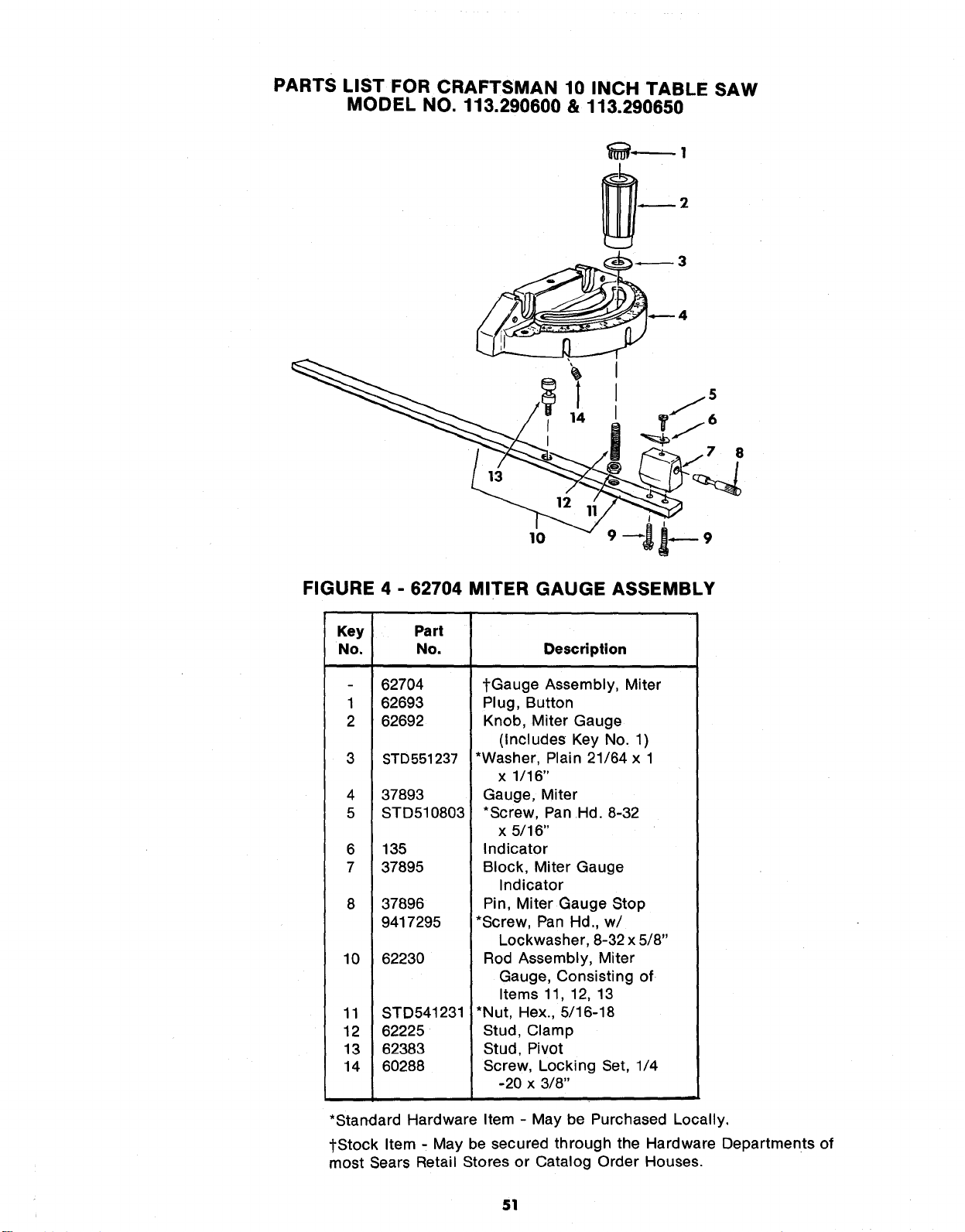
PARTS LIST FOR CRAFTSMAN 10 INCH TABLE SAW
MODEL NO. 113.290600 & 113.290650
3
4
14
8
I
FIGURE 4 - 62704 MITER GAUGE ASSEMBLY
Key
No.
1
2
3
4
5
6
7
8
10
11
12
13
14
Part
No.
62704
62693
62692
STD551237
37893
STD510803
135
37895
37896
9417295
62230
STD541231
62225
62383
60288
Description
tGauge Assembly, Miter
Plug, Button
Knob, Miter Gauge
(Includes Key No. 1)
*Washer, Plain 21/64 x 1
x 1/16"
Gauge, Miter
*Screw, Pan Hd. 8-32
x 5/16"
Indicator
Block, Miter Gauge
Indicator
Pin, Miter Gauge Stop
*Screw, Pan Hd., w/
Lockwasher, 8-32 x 5/8"
Rod Assembly, Miter
Gauge, Consisting of
Items 11, 12, 13
*Nut, Hex., 5/16-18
Stud, Clamp
Stud, Pivot
Screw, Locking Set, 1/4
-20 x 3/8"
*Standard Hardware Item - May be Purchased Locally,
tStock Item - May be secured through the Hardware Departments of
most Sears Retail Stores or Catalog Order Houses.
51
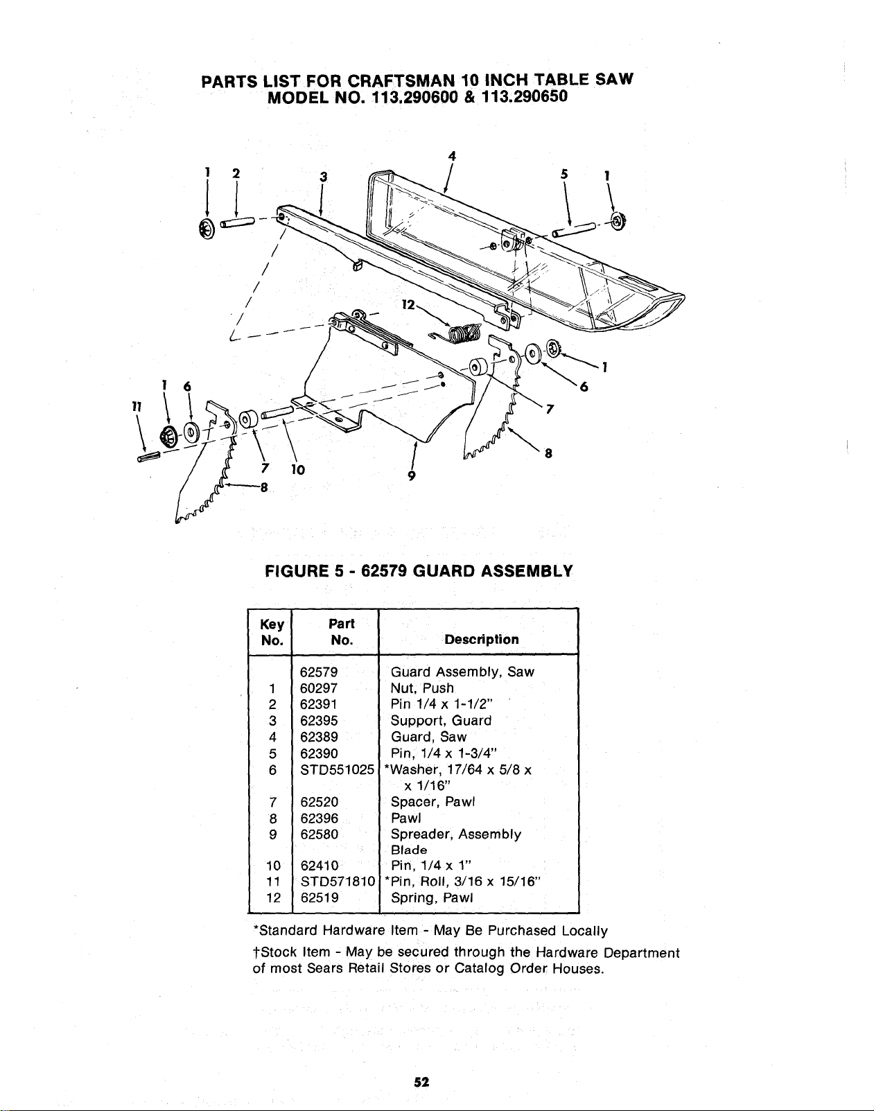
PARTS LIST FOR CRAFTSMAN 10 INCH TABLE SAW
MODEL NO. 113.290600 & 113.290650
1 2
II
/
/
/
/
/
\
7 10
4
\
5 1
8
FIGURE 5 - 62579 GUARD ASSEMBLY
Key Part
No. No.
62579
1 60297
2 62391
3 62395
4 62389
5 62390
6 STD551025
7 62520
8 62396
9 62580
10 62410
11 STD571810
12 62519
Description
Guard Assembly, Saw
Nut, Push
Pin 1/4 x 1-1/2"
Support, Guard
Guard, Saw
Pin, 1/4 x 1-3/4"
*Washer, 17/64 x 5/8 x
x 1/16"
Spacer, Pawl
Pawl
Spreader, Assembly
Blade
Pin, 1/4 x 1"
*Pin, Roll, 3/16 x 15/16"
Spring, Pawl
*Standard Hardware Item - May Be Purchased Locally
tStock Item - May be secured through the Hardware Department
of most Sears Retail Stores or Catalog Order Houses.
52
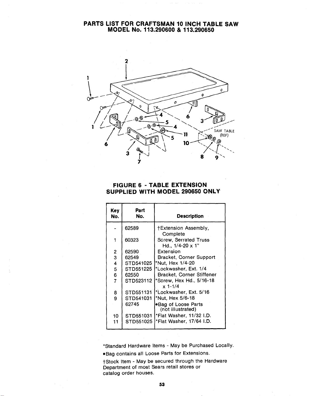
PARTS LIST FOR CRAFTSMAN 10 INCH TABLE SAW
MODEL No. 113.290600 & 113.290650
2
1
FIGURE 6 - TABLE EXTENSION
SUPPLIED WITH MODEL 290650 ONLY
Key Part
No. No.
2
3
4
5
6
7
8
9
62589
60323
62590
62549
STD541025
STD551225
62550
STD523112
STD551131
STD541031
62745
10 STD551031
11 STD551025
Description
tExtension Assembly,
Complete
Screw, Serrated Truss
Hd., 1/4-20 x 1"
Extension
Bracket, Corner Support
*Nut, Hex 1/4-20
*Lockwasher, Ext. 1/4
Bracket, Corner Stiffener
*Screw, Hex Hd., 5/16-18
x 1-1/4
*Lockwasher, Ext. 5/16
*Nut, Hex 5/6-18
,Bag of Loose Parts
(not illustrated)
*Flat Washer, 11/32 I.D,
*Flat Washer, 17/64 I.D.
*Standard Hardware Items - May be Purchased Locally.
eBag contains all Loose Parts for Extensions.
{Stock Item - May be secured through the Hardware
Department of most Sears retail stores or
catalog order houses.
53
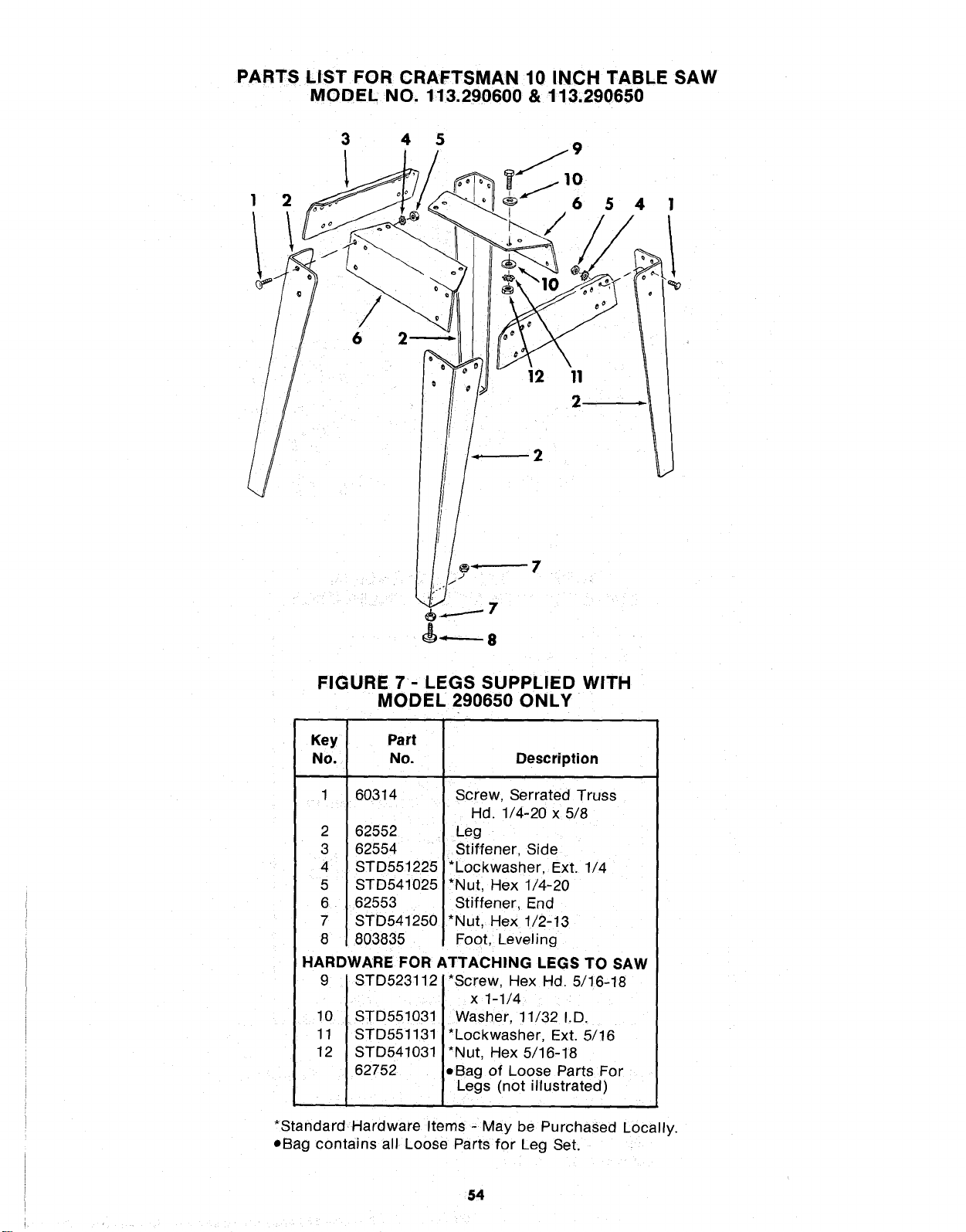
PARTS LIST FOR CRAFTSMAN 10 INCH TABLE SAW
MODEL NO. 113.290600 & 113.290650
3 4 5
1 1t. 9
2 6 5 4
6
12 11
2
_------- 8
FIGURE 7 - LEGS SUPPLIED WITH
MODEL 290650 ONLY
Key
No,
1
2
3
4
5
6
7
8
Part
No.
60314
62552
62554
STD551225
STD541025
62553
STD541250
803835
Description
J
Screw, Serrated Truss
Hd. 1/4-20 x 5/8
Leg
Stiffener, Side
*Lockwasher, Ext. 1/4
*Nut, Hex 1/4-20
Stiffener, End
*Nut, Hex 1/2-13
Foot, Leveling
HARDWARE FOR ATTACHING LEGS TO SAW
9 STD523112 *Screw, Hex Hd. 5/16-18
x 1-1/4
10 . STD551031. Washer, 11/32 I.D.
11 STD551131 *Lockwasher, Ext. 5/16
12 STD541031 *Nut, Hex 5/16-18
62752 eBag of Loose Parts For
Legs (not illustrated)
*Standard Hardware Items - May be Purchased Locally.
oBag contains all Loose Parts for Leg Set.
54

z_
I-- _z
z_O
_z
_ -
g
i-I" Z .__
:_Z:_
_=o _ _ _
o++
°_ z _ =_
z_ = _
_w E _ _-
o
_,=,,
5=+
,-, <
.=.,
l-P
.,+, =
= -_ =+
= P.3__
I-=- I'-" €_
= = _ _
• _
•,++_,++
+
2'
N
+.-+°°+._
++°_++
,.- _ _; "_= _ _
•- ,_
_ _ .
: : _.'_
I-- m
r_
o (I) I-,-
_ o x:=
I= =1
,k
55
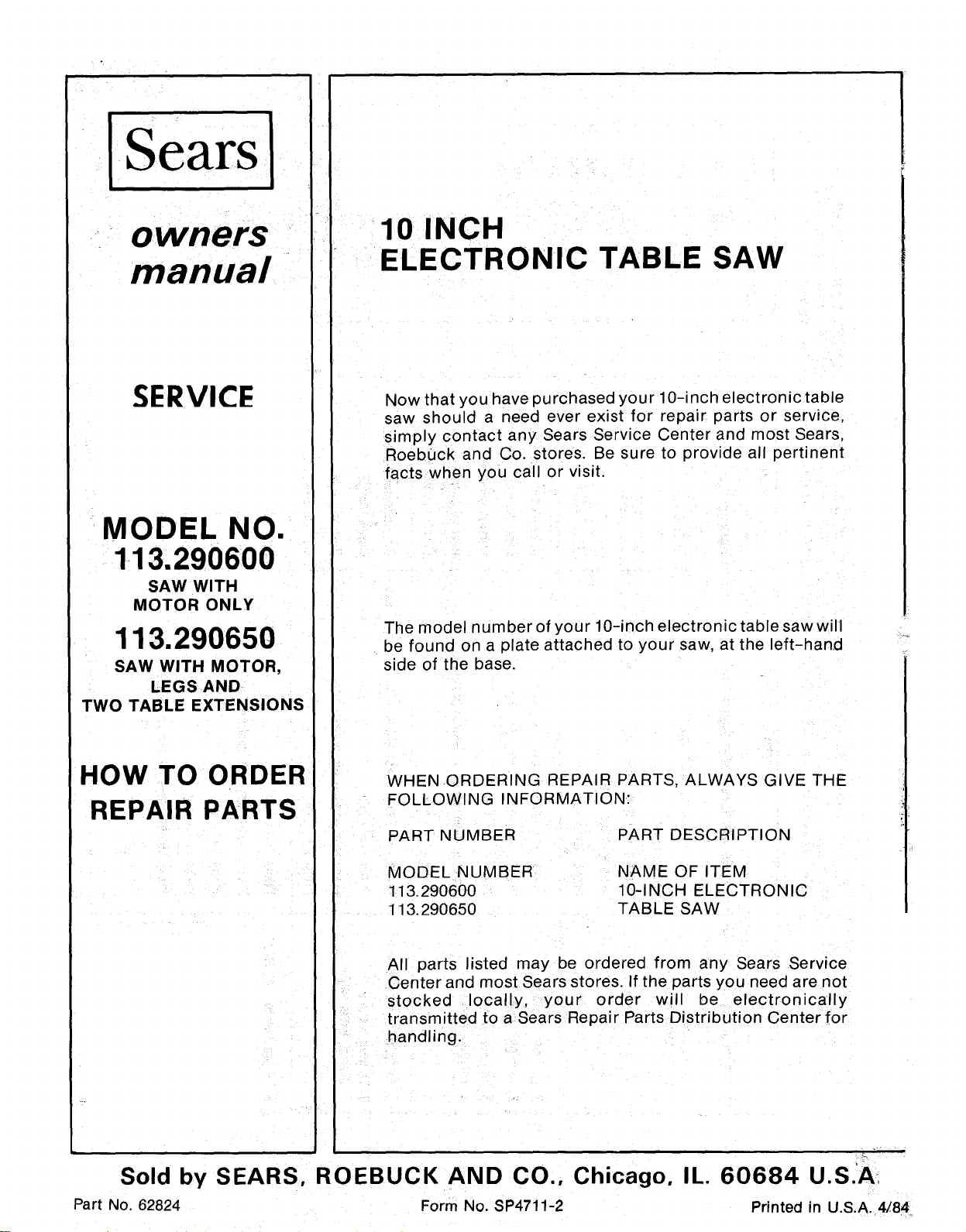
Sears
owners
manual
SERVICE
MODEL NO.
113.290600
SAW WITH
MOTOR ONLY
113.290650
SAW WITH MOTOR,
LEGS AND
TWO TABLE EXTENSIONS
HOW TO ORDER
REPAIR PARTS
10 INCH
ELECTRONIC TABLE SAW
Now that you have purchased your 10-inch electronic table
saw should a need ever exist for repair parts or service,
simply contact any Sears Service Center and most Sears,
Roebuck and Co. stores. Be sure to provide all pertinent
facts when you call or visit.
The model number of your 10-inch electronic table saw will
be found on a plate attached to your saw, at the left-hand
side of the base.
WHEN .ORDERING REPAIR PARTS, ALWAYS GIVE THE
FOLLOWING INFORMATION:
PART NUMBER PART DESCRIPTION
MODEL NUMBER
113.290600
113.290650
NAME OF ITEM
10-INCH ELECTRONIC
TABLE SAW
All parts listed may be ordered from any Sears Service
Center and most Sears stores. If the parts you need are not
stocked locally, your order will be electronically
transmitted to a Sears Repair Parts Distribution Center for
handling.
Sold by SEARS, ROEBUCK AND CO., Chicago, IL. 60684 U.S.A
Part No. 62824 Form No. SP4711-2 Printed in U.S.A. 4/84