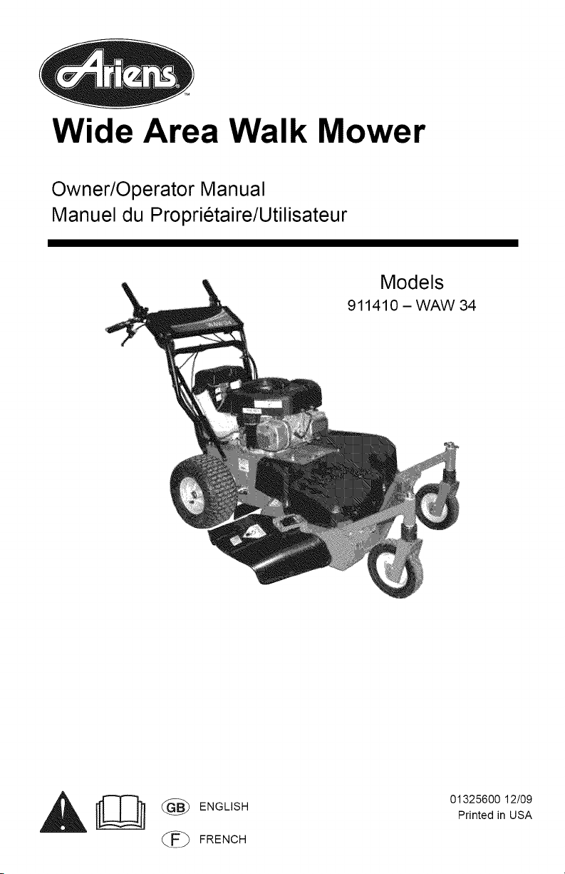
Wide Area Walk Mower
Owner/Operator Manual
Manuel du Proprietaire/Utilisateur
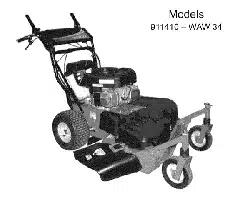
Models
911410 - WAW 34
_ _ ENG',SH
(_ FRENCH
01325600 12/09
Printed in USA
/ q:1:] 1:1 [o]_ _o]_l / :l_ll_'_
Safety ........................... 4
Assembly ........................ 9
Controls and Features ............. 11
Operation ....................... 12
Maintenance ..................... 16
Service and Adjustments .......... 19
Storage ......................... 23
Troubleshooting .................. 24
Service Parts .................... 25
Accessories ..................... 25
Specifications ................... 26
Warranty ........................ 27
NON-ENGLISH MANUALS
Manuals in languages other than
English may be obtained from
your Dealer. Visit your dealer or
w_v.ariens.com for a list of
languages available for your
equipment.
Manuals printed in languages
other than English are also
available as a free download on
our website:
http://www.ariens.com
MANUALES EN IDIOMAS
DIFERENTES DEL INGLES
Puede obtener manuales en
idiomas diferentes del ingles en su
distribuidor. Visite a su distribuidor
o vaya a w_v.ariens.com para
obtener una lista de idiomas
disponibles para su equipo.
Tambien puede imprimir manuales
en idiomas diferentes del ingles
descargandolos gratuitamente de
nuestra pagina Web:
htt p://www.ariens.com
MANUELS NON ANGLAIS
Des manuels dans differentes
langues sont disponibles chez
votre revendeur. Rendez-vous
chez votre revendeur ou allez sur
le site w_v.ariens.com pour
consulter la liste des langues
disponibles pour votre equipement.
Les manuels imprimes dans des
langues differentes de I'anglais
sont egalement disponibles en
telechargement gratuit sur notre
site Web :
http://www.ariens.com
THE MANUAL
Before using the unit, carefully and
completely read your manuals. The contents
will give you an understanding of safety
instructions and controls during normal
operation and maintenance.
All reference to left, right, front, or rear are
given from the operator's position, facing the
direction of forward travel.
SERVICE AND REPLACEMENT
PARTS
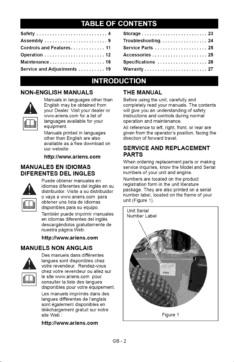
When ordering replacement parts or making
service inquiries, know the Model and Serial
numbers of your unit and engine.
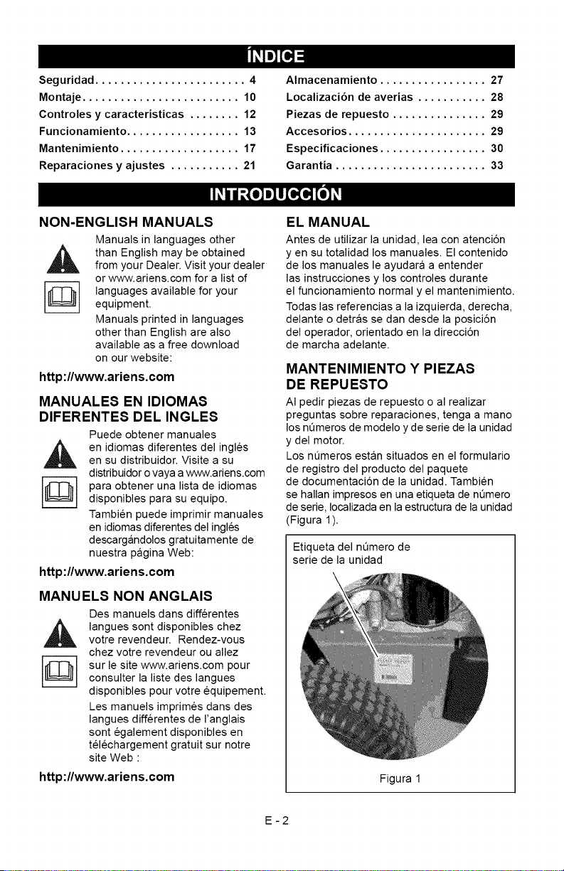
Numbers are located on the product
registration form in the unit literature
package. They are also printed on a serial
number label, located on the frame of your
unit (Figure 1).
Unit Serial
Number Label
Figure 1
GB-2
•RecordUnitModelandSerialnumbers
here:
l J
• Record Engine Model & Serial numbers
here:
[ J
PRODUCT REGISTRATION
The Ariens dealer must register the product
at the time of purchase. Registering the
product will help the company process
warranty claims or contact you with the latest
service information. All claims meeting
requirements during the limited warranty
period will be honored, whether or not the
product registration card is returned. Keep a
proof of purchase if you do not register your
unit.
Customer Note: If the Dealer does not
register your product, please fill out, sign and
return the product registration card to Ariens
or go to www.ariens.com on the internet.
UNAUTHORIZED REPLACEMENT
PARTS
Use only Ariens replacement parts.
Replacing any part on this vehicle with
anything other than an Ariens authorized
replacement part may adversely affect the
performance, durability, or safety of this unit
and may void the warranty. Ariens disclaims
liability for any claims or damages, whether
warranty, property damage, personal injury or
death arising out of the use of unauthorized
replacement parts. To locate your nearest
Ariens Dealer, go to www.ariens.com on the
internet.
DEALER DELIVERY
Dealer should:
1. Check that all assembly and
adjustments have been properly
completed.
2. Fill out Original Purchaser Registration
Card and return the card to Ariens.
3. Explain Ariens Limited Warranty Policy.
4. Explain recommended lubrication and
maintenance. Advise customer on
adjustments. Remind customer to
change oil in 4 cycle engine crankcase
after first five (5) hours of operation.
5. Instruct customer on controls and
operation of unit. Discuss and
emphasize the Safety Rules. Give
customer Owner/Operator, Parts, and
Engine manuals. Advise customer to
thoroughly read and understand them.
DISCLAIMER
Ariens reserves the right to discontinue,
make changes to, and add improvements
upon its products at any time without public
notice or obligation.The descriptions and
specifications contained in this manual were
in effect at printing. Equipment described
within this manual may be optional. Some
illustrations may not apply to your unit.
GB-3
[,,"/-'I=1=l i'l
,&
WARNING: This cutting machine
is capable of amputating hands
and feet and throwing objects.
Failure to observe the safety
instructions in the manuals and
on decals could result in serious
injury or death.
Slopes are a major factor related
to slip and fall accidents.
Operation on all slopes requires
extra caution.
Tragic accidents can occur if the
operator is not alert to the
presence of children. Never
assume that children will remain
where you last saw them.
Gasoline is extremely flammable
and the vapors are explosive,
handle with care.
Stop unit and engine, remove key
(if equipped) and allow moving
parts to stop before leaving
operator's position.
SAFETY ALERTS
Look for these symbols to point
,_ out important safety precautions.
They mean:
Attention!
Personal Safety Is Involved!
Become Alert!
Obey The Message!
The safety alert symbols above and signal
words below are used on decals and in this
manual.
Read and understand all safety messages.
DANGER: IMMINENTLY
HAZARDOUS SITUATION! If not
avoided, WILL RESULT in death or
serious injury.
WARNING: POTENTIALLY
HAZARDOUS SITUATION! If not
avoided, COULD RESULT in
death or serious injury.
A
CAUTION: POTENTIALLY
HAZARDOUS SITUATION! If not
avoided, MAY RESULT in minor or
moderate injury. It may also be
used to alert against unsafe
practices.
NOTATIONS
NOTE: General reference information for
proper operation and maintenance practices.
IMPORTANT: Specific procedures or
information required to prevent damage to
unit or attachment.
PRACTICES AND LAWS
Practice usual and customary safe working
precautions, for the benefit of yourself and
others. Understand and follow all safety
messages. Be alert to unsafe conditions and
the possibility of minor, moderate, or serious
injury or death. Learn applicable rules and
laws in your area.
REQUIRED OPERATOR
TRAINING
Original purchaser of this unit was instructed
by the seller on safe and proper operation. If
anyone other than the original purchaser will
use the unit, ALWAYS provide this manual
and any needed safety training before
operation.
GB-4
SAFETY DECALS AND
LOCATIONS
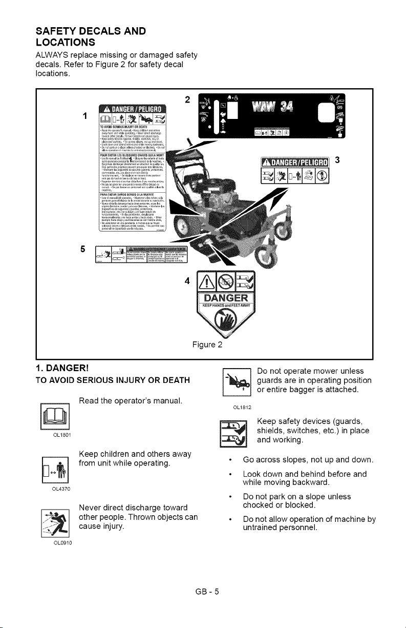
ALWAYS replace missing or damaged safety
decals. Refer to Figure 2 for safety decal
locations.
5
Figure 2
1. DANGER!
TO AVOIDSERIOUS INJURY OR DEATH
Read the operator's manual.
OL180I
©L4370
Keep children and others away
from unit while operating.
OL0910
Never direct discharge toward
other people. Thrown objects can
cause injury.
I_ o not operate mower unless
guards are in operating position
or entire bagger is attached.
©L1812
l_ Keep safety devices (guards,
shields, switches, etc.) in place
and working.
Go across slopes, not up and down.
Look down and behind before and
while moving backward.
Do not park on a slope unless
chocked or blocked.
Do not allow operation of machine by
untrained personnel.
GB-5
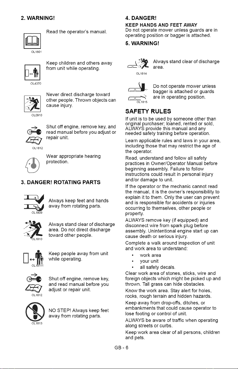
2. WARNING!
Read the operator's manual.
OL180I
©L4370
Keep children and others away
from unit while operating.
OL0910
Never direct discharge toward
other people. Thrown objects can
cause injury.
©L1812
Shut off engine, remove key, and
read manual before you adjust or
repair unit.
Wear appropriate hearing
protection.
3. DANGER! ROTATING PARTS
OL1809
Always keep feet and hands
away from rotating parts.
Always stand clear of discharge
area. Do not direct discharge
toward other people.
©L1812
®
OL1813
Keep people away from unit
while operating.
Shut off engine, remove key,
and read manual before you
adjust or repair unit.
NO STEP! Always keep feet
away from rotating parts.
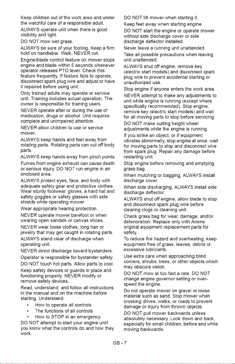
4. DANGER!
KEEP HANDS AND FEET AWAY
Do not operate mower unless guards are in
operating position or bagger is attached.
5. WARNING!
¢_ AIwaySarea.stand clearofdischarge
©L1814
÷ Do not operate mower unless
bagger is attached or guards
are in operating position.
OLI815
SAFETY RULES
If unit is to be used by someone other than
original purchaser; loaned, rented or sold,
ALWAYS provide this manual and any
needed safety training before operation.
Learn applicable rules and laws in your area,
including those that may restrict the age of
the operator.
Read, understand and follow all safety
practices in Owner/Operator Manual before
beginning assembly. Failure to follow
instructions could result in personal injury
and/or damage to unit.
If the operator or the mechanic cannot read
the manual, it is the owner's responsibility to
explain it to them. Only the user can prevent
and is responsible for accidents or injuries
occurring to themselves, other people or
property.
ALWAYS remove key (if equipped) and
disconnect wire from spark plug before
assembly. Unintentional engine start up can
cause death or serious injury.
Complete a walk around inspection of unit
and work area to understand:
work area
your unit
all safety decals.
Clear work area of stones, sticks, wire and
foreign objects which might be picked up and
thrown. Tall grass can hide obstacles.
Know the work area. Stay alert for holes,
rocks, rough terrain and hidden hazards.
Keep away from drop-offs, ditches, or
embankments that could cause operator to
lose footing or control of unit.
ALWAYS be aware of traffic when operating
along streets or curbs.
Keep work area clear of all persons, children
and pets.
GB-6
Keepchildrenoutoftheworkareaandunder
thewatchfulcareofaresponsibleadult.
ALWAYSoperateunitwhenthereisgood
visibilityandlight.
DONOTmowwetgrass.
ALWAYSbesureofyourfooting.Keepafirm
holdonhandlebar.Walk,NEVERrun.
Engine/bladecontrolfeatureonmowerstops
engineandbladewithin5secondswhenever
operatorreleasesPTOlever.Checkthis
featurefrequently.Iffeaturefailstooperate,
disconnectsparkplugwireandadjustorhave
itrepairedbeforeusingunit.
Onlytrainedadultsmayoperateorservice
unit.Trainingincludesactualoperation.The
ownerisresponsiblefortrainingusers.
NEVERoperateafterorduringtheuseof
medication,drugsoralcohol.Unitrequires
completeandunimpairedattention.
NEVERallowchildrentouseorservice
mower.
ALWAYSkeephandsandfeetawayfrom
rotatingparts.Rotatingpartscancutoffbody
parts.
ALWAYSkeephandsawayfrompinchpoints.
Fumesfromengineexhaustcancausedeath
orseriousinjury.DONOTrunengineinan
enclosedarea.
ALWAYSprotecteyes,face,andbodywith
adequatesafetygearandprotectiveclothes.
Wearsturdyfootwear,gloves,ahardhatand
safetygogglesorsafetyglasseswithside
shieldswhileoperatingmower.
Wearappropriatehearingprotection.
NEVERoperatemowerbarefootorwhen
wearingopensandalsorcanvasshoes.
NEVERwearlooseclothes,longhairor
jewelrythatmaygetcaughtinrotatingparts.
ALWAYSstandclearofdischargewhen
operatingunit.
NEVERdirectdischargetowardbystanders.
Operatorisresponsibleforbystandersafety.
DONOTtouchhotparts.Allowpartstocool.
Keepsafetydevicesorguardsinplaceand
functioningproperly.NEVERmodifyor
removesafetydevices.
Read,understand,andfollowallinstructions
inthemanualandonthemachinebefore
starting.Understand:
Howtooperateallcontrols
Thefunctionsofallcontrols
HowtoSTOPinanemergency.
DONOTattempttostartyourengineuntil
youknowwhatthecontrolsdoandhowthey
work.
DONOTtiltmowerwhenstartingit.
Keepfeetawaywhenstartingengine.
DONOTstarttheengineoroperatemower
withoutsidedischargecoverorside
dischargedeflectorinstalled.
Neverleavearunningunitunattended.
Takeallpossibleprecautionswhenleaving
unitunattended.
ALWAYSshutoffengine,removekey
(electricstartmodels)anddisconnectspark
plugwiretopreventaccidentalstartingor
unauthorizeduse.
Stopengineifanyoneenterstheworkarea.
NEVERattempttomakeanyadjustmentsto
unitwhileengineisrunning(exceptwhere
specificallyrecommended).Stopengine,
removekey(electricstartmodels)andwait
forallmovingpartstostopbeforeservicing.
DONOTmakecuttingheightwheel
adjustmentswhiletheengineisrunning.
Ifyoustrikeanobject,orifequipment
vibratesabnormally,stopengineatonce,wait
formovingpartstostopanddisconnectwire
fromsparkplug.Repairanydamagebefore
restartingunit.
Stopenginebeforeremovingandemptying
grassbag.
Whenmulchingorbagging,ALWAYSinstall
dischargecover.
Whensidedischarging,ALWAYSinstallside
dischargedeflector.
ALWAYSshutoffengine,allowbladetostop
anddisconnectsparkplugwirebefore
clearingclogsorcleaningunit.
Checkgrassbagforwear,damage,and/or
deterioration.ReplaceonlywithAriens
originalequipmentreplacementpartsfor
safety.
Toreducefirehazardandoverheating,keep
equipmentfreeofgrass,leaves,debrisor
excessivelubricants.
Useextracarewhenapproachingblind
corners,shrubs,trees,orotherobjectswhich
mayobscurevision.
DONOTmowattoofastarate.DONOT
changeenginegovernorsettingorover-
speedtheengine.
Donotoperatemowerongravelorloose
materialsuchassand.Stopmowerwhen
crossingdrives,walks,orroadstoprevent
damageorinjuryfromthrownobjects.
DONOTpullmowerbackwardsunless
absolutelynecessary.Lookdownandback,
especiallyforsmallchildren,beforeandwhile
movingbackwards.
GB-7
Onself-propelledmodels,releasingwheel
drivecontrolmuststopmower'sforward
movement.Ifthisfeaturefailstooperate,
disconnectsparkplugwireandrepairbefore
usingunit.
Onself-propelledmodels,wheeldrivemust
bedisengagedwhenstartingengine.
DONOToperateonsteepslopes.
NEVERleaveunitunattendedonaslope.
Chockwheelsifparkingonaslope.
Mowacrossthefaceofslopes,neverupand
down.Beespeciallycautiouswhenchanging
directiononslopes.
Thisproductisequippedwithaninternal
combustionengine.DONOTuseonornear
anyunimproved,forestorbrushcoveredland
unlesstheexhaustsystemisequippedwitha
sparkarrestormeetingapplicablelocal,state
orfederallaws.Asparkarrestor,ifused,
mustbemaintainedineffectiveworkingorder
bytheoperator.SeeyourAriensDealeror
enginemanufacturer'sservicecenter.
EmissionControlSystem
CertificationLabel
NOTE:Tamperingwithemissioncontrolsand
componentsbyunauthorizedpersonnelmay
resultinseverefinesorpenalties.Emission
controlsandcomponentscanonlybe
adjustedbyEPAand/orCARBauthorized
servicecenters.ContactyourAriens
EquipmentRetailerconcerningemission
controlsandcomponentquestions.
Fuelishighlyflammableanditsvaporscan
explode.ONLYuseapprovedfuelcontainers.
NOSmoking!
NOSparks!
NOFlames!
Allowenginetocoolbeforefillingfuel
tank.
Neverfillcontainersinsideavehicleorona
truckortrailerbedwithaplasticliner.Always
placecontainersonthegroundawayfrom
yourvehiclebeforefilling.
Whenpractical,removegas-powered
equipmentfromthetruckortrailerandrefuel
itontheground.Ifthisisnotpossible,then
refuelsuchequipmentonatrailerwitha
portablecontainer,ratherthanfroma
gasolinedispensernozzle.
Keepthenozzleincontactwiththerimofthe
fueltankorcontaineropeningatalltimesuntil
fuelingiscomplete.Donotuseanozzlelock-
opendevice.
Checkfuelsupplybeforestartingengine.
DONOTfillgasolinetankindoors,when
engineisrunning,orwhileengineishot.
Allowenginetocoolseveralminutesbefore
removingfuelcap.
DONOToverfill.Allowabout1/4"(6mm)of
tankspaceforfuelexpansion.
Replacegasolinetankcapsecurelyand
cleananyspilledfuelbeforestartingengine.
Iffuelisspilledonclothing,changeclothing
immediately.
NEVERstorefuelinsidewherethereisan
openflame,suchasawaterheater.
ALWAYSdrainfueloutdoorsawayfrom
ignitionsources.
ALWAYSshutoffandremovekey,engine
whentransportingunitonatruckortrailer.
AvoidElectricShock.DONOTdisconnect
wirefromsparkplugwhileengineisrunning.
DoNOTputbatteryinfireormutilate.
ExplosiveGases!
NOflames,NOsparks,NOsmoking,near
battery.
Poisonousbatteryfluidcontainssulfuricacid.
Contactwithskin,eyesorclothingcancause
severechemicalburns.
ALWAYSwearsafetyglassesandprotective
gearnearbattery.
ALWAYSkeepbatteriesoutofreachof
children.
Batteryposts,terminalsandrelated
accessoriescontainleadandlead
compounds,chemicalsknowntotheStateof
Californiatocausecancerandreproductive
harm.Washhandsafterhandling.
Chargebatteriesinanopen,well-ventilated
area,awayfromsparkandflames.Unplug
chargerbeforeconnectingordisconnecting
battery.Wearprotectiveclothinganduse
insulatedtools.
Accidentalenginestartupcancausedeathor
seriousinjury.Exceptwherespecifically
recommended,ALWAYSstopengine,
removekey(electricstartmodels),waitfor
movingpartstostop,allowpartstocooland
disconnectsparkplugwirebeforeinspecting,
servicing,adjustingorrepairingunit.
Keepmowerfreeofgrass,leaves,orother
debrisbuild-up.
Keepequipmentingoodcondition.
Maintainorreplacesafetyandinstruction
labels,asnecessary.
Followenginemanufacturer'ssafety
instructionwhenservicingengine.
Checkallhardwareatregularintervals,
especiallybladeattachmentbolts.Keepall
hardwareproperlytightened.
GB-8
Anextensionspring,whenextended,stores
energyandcanbedangerous.Alwaysuse
toolsspecificallydesignedforinstallingor
removinganextensionspring.Always
compressorextendspringsslowly.
Beforetippingunit,removefuelandbattery(if
equipped).
Useextracarewhenloadingorunloading
unitontotrailerortruck.
Ensureallwheelblocks,jackstandsandtie
downswillsupportunitduringmaintenance.
Replaceworn-outmufflersimmediately.
Continuedusecouldresultinfireor
explosion.
Sharpedgescancutoramputatefingersora
hand.Wrapbladeorwearsturdyglovesto
service.
Onlyreplaceblades.NEVERstraightenor
weld blades.
Use only replacement parts designed for your
unit. See your Ariens Dealer.
Allow engine to cool before storing in any
enclosure.
ALWAYS clean unit before extended storage.
See engine manual for proper storage.
DO NOT store unit inside a building with fuel
in the fuel tank where any ignition sources
are present.
Use only accessories which have been
approved by Ariens and are properly
installed.
Use only accessories or attachments that are
designed for your unit and that can be used
safely on your terrain.
Check attachments frequently and replace
worn or damaged components with
manufacturer's recommended parts.
7_,_,.."_"]=1_N-']_'d
CAUTION: AVOID INJURY. Read
and understand the entire Safety
section before proceeding.
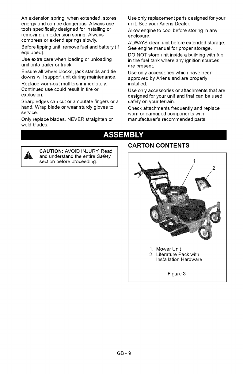
CARTON CONTENTS
1. Mower Unit
2. Literature Pack with
Installation Hardware
Figure 3
GB-9
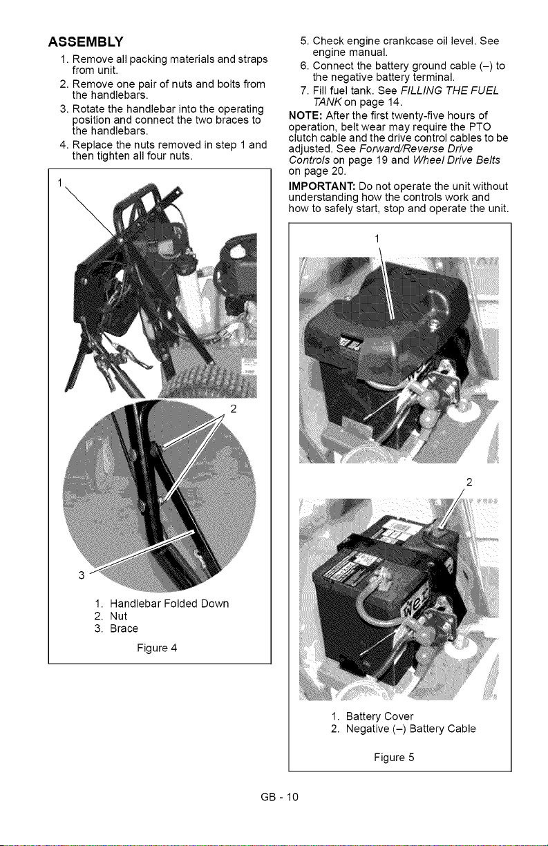
ASSEMBLY
1. Remove all packing materials and straps
from unit.
2. Remove one pair of nuts and bolts from
the handlebars.
3. Rotate the handlebar into the operating
position and connect the two braces to
the handlebars.
4. Replace the nuts removed in step 1 and
then tighten all four nuts.
1. Handlebar Folded Down
2. Nut
3. Brace
Figure 4
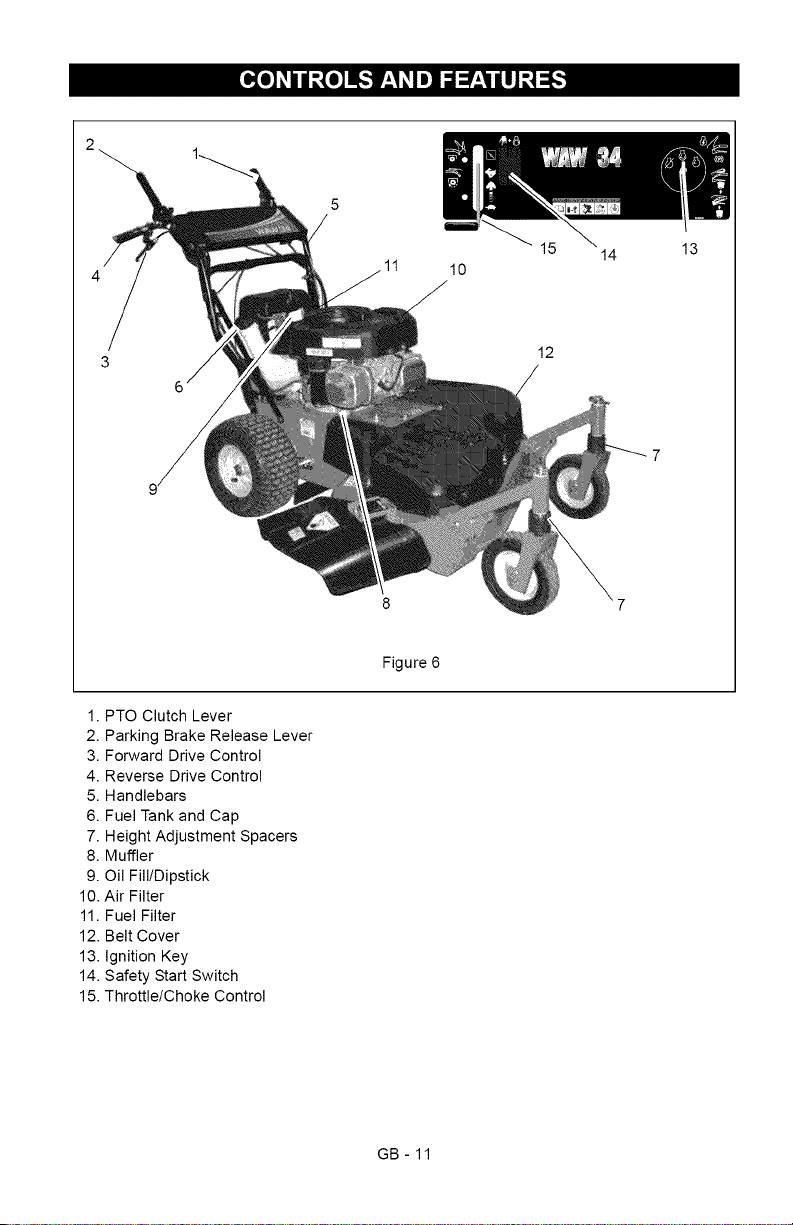
5. Check engine crankcase oil level. See
engine manual.
6. Connect the battery ground cable (-) to
the negative battery terminal.
7. Fill fuel tank. See FILLING THE FUEL
TANKon page 14.
NOTE: After the first twenty-five hours of
operation, belt wear may require the PTO
clutch cable and the drive control cables to be
adjusted. See Forward/Reverse Drive
Controls on page 19 and Wheel Drive Belts
on page 20.
IMPORTANT: Do not operate the unit without
understanding how the controls work and
how to safely start, stop and operate the unit.
2
1. Battery Cover
2. Negative (-) Battery Cable
Figure 5
GB - 10
11
14
10
12
13
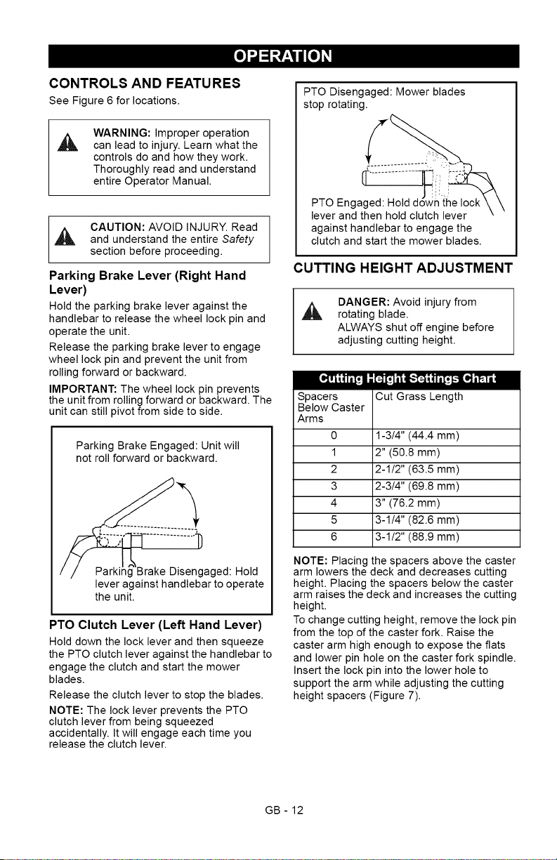
Figure 6
1. PTO Clutch Lever
2. Parking Brake Release Lever
3. Forward Drive Control
4. Reverse Drive Control
5. Handlebars
6. Fuel Tank and Cap
7. Height Adjustment Spacers
8. Muffler
9. Oil Fill/Dipstick
10. Air Filter
11. Fuel Filter
12. Belt Cover
13. Ignition Key
14. Safety Start Switch
15. Throttle/Choke Control
GB- 11
CONTROLS AND FEATURES
See Figure 6 for locations.
WARNING: Improper operation
,_ can lead to injury. Learn what the
controls do and how they work.
Thoroughly read and understand
entire Operator Manual.
CAUTION: AVOID INJURY. Read
and understand the entire Safety
section before proceeding.
Parking Brake Lever (Right Hand
Lever)
Hold the parking brake lever against the
handlebar to release the wheel lock pin and
operate the unit.
Release the parking brake lever to engage
wheel lock pin and prevent the unit from
rolling forward or backward.
IMPORTANT: The wheel lock pin prevents
the unit from rolling forward or backward. The
unit can still pivot from side to side.
Parking Brake Engaged: Unit will
not roll forward or backward.
gaged: Hold
lever against handlebar to operate
the unit.
PTO Clutch Lever (Left Hand Lever)
Hold down the lock lever and then squeeze
the PTO clutch lever against the handlebar to
engage the clutch and start the mower
blades.
Release the clutch lever to stop the blades.
NOTE: The lock lever prevents the PTO
clutch lever from being squeezed
accidentally. It will engage each time you
release the clutch lever.
PTO Disengaged: Mower blades
stop rotating.
PTO Engaged:
lever and then hold clutch lever
against handlebar to engage the
clutch and start the mower blades.
CUTTING HEIGHT ADJUSTMENT
DANGER: Avoid injury from
rotating blade.
ALWAYS shut off engine before
adjusting cutting height.
Spacers Cut Grass Length
Below Caster
Arms
0 1-3!4" (44.4 mm)
1 2" (50.8 mm)
2 2-1!2" (63.5 mm)
3 2-3!4" (69.8 mm)
4 3" (76.2 mm)
5 3-1!4" (82.6 mm)
6 3-1!2" (88.9 mm)
NOTE: Placing the spacers above the caster
arm lowers the deck and decreases cutting
height. Placing the spacers below the caster
arm raises the deck and increases the cutting
height.
To change cutting height, remove the lock pin
from the top of the caster fork. Raise the
caster arm high enough to expose the flats
and lower pin hole on the caster fork spindle.
Insert the lock pin into the lower hole to
support the arm while adjusting the cutting
height spacers (Figure 7).
GB - 12
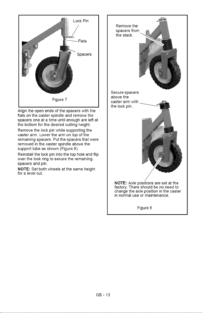
LockPin
Spacers
Figure7
Aligntheopenendsofthespacerswiththe
flatsonthecasterspindleandremovethe
spacersoneatatimeuntilenoughareleftat
thebottomforthedesiredcuttingheight.
Removethelockpinwhilesupportingthe
casterarm.Lowerthearmontopofthe
remainingspacers.Putthespacersthatwere
removedinthecasterspindleabovethe
supporttubeasshown(Figure8).
Reinstallthelockpinintothetopholeandflip
overthelockringtosecuretheremaining
spacersandpin.
NOTE:Setbothwheelsatthesameheight
foralevelcut.
Removethe
spacersfrom
thestack.
Securespacers
abovethe
casterarmwith
thelockpin.
NOTE:Axlepositionsaresetatthe
factory.Thereshouldbenoneedto
changetheaxlepositioninthecaster
innormaluseormaintenance.
Figure8
GB-13
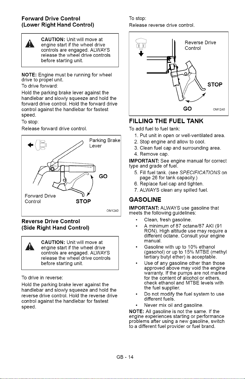
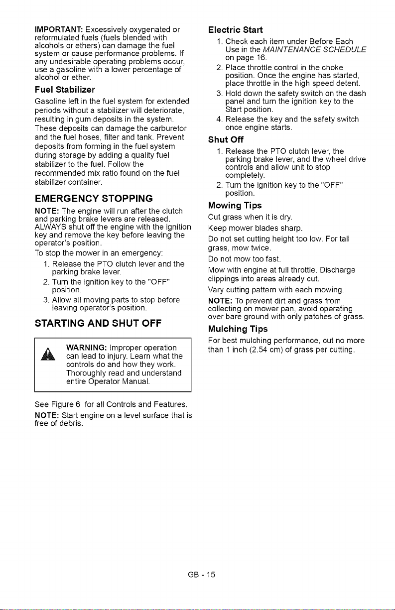
Forward Drive Control To stop:
(Lower Right Hand Control) Release reverse drive control.
CAUTION: Unit will move at
engine start if the wheel drive
controls are engaged. ALWAYS
release the wheel drive controls
before starting unit.
NOTE: Engine must be running for wheel
drive to propel unit.
To drive forward:
Hold the parking brake lever against the
handlebar and slowly squeeze and hold the
forward drive control. Hold the forward drive
control against the handlebar for fastest
speed.
To stop:
Release forward drive control.
,, _ ,_ Parking Brake
_.', _1_.. Lever
...¢::....... GO
Forward Drive
Control STOP
OM1240
Reverse Drive Control
(Side Right Hand Control)
CAUTION: Unit will move at
engine start if the wheel drive
controls are engaged. ALWAYS
release the wheel drive controls
before starting unit.
To drive in reverse:
Hold the parking brake lever against the
handlebar and slowly squeeze and hold the
reverse drive control. Hold the reverse drive
control against the handlebar for fastest
speed.
Reverse Drive
Control
STOP
GO OM1240
FILLING THE FUEL TANK
To add fuel to fuel tank:
1. Put unit in open or well-ventilated area.
2. Stop engine and allow to cool.
3. Clean fuel cap and surrounding area.
4. Remove cap.
IMPORTANT: See engine manual for correct
type and grade of fuel.
5. Fill fuel tank. (see SPECIFICATIONS on
page 26 for tank capacity.)
6. Replace fuel cap and tighten.
7. ALWAYS clean any spilled fuel.
GASOLINE
IMPORTANT: ALWAYS use gasoline that
meets the following guidelines:
Clean, fresh gasoline.
A minimum of 87 octane/87 AKI (91
RON). High altitude use may require a
different octane. Consult your engine
manual.
Gasoline with up to 10% ethanol
(gasohol) or up to 15% MTBE (methyl
tertiary butyl ether) is acceptable.
Use of any gasoline other than those
approved above may void the engine
warranty. If the pumps are not marked
for the content of alcohol or ethers,
check ethanol and MTBE levels with
the fuel supplier.
Do not modify the fuel system to use
different fuels.
Never mix oil and gasoline.
NOTE: All gasoline is not the same. If the
engine experiences starting or performance
problems after using a new gasoline, switch
to a different fuel provider or fuel brand.
GB - 14
IMPORTANT:Excessivelyoxygenatedor
reformulatedfuels(fuelsblendedwith
alcoholsorethers)candamagethefuel
systemorcauseperformanceproblems.If
anyundesirableoperatingproblemsoccur,
useagasolinewithalowerpercentageof
alcoholorether.
Fuel Stabilizer
Gasoline left in the fuel system for extended
periods without a stabilizer will deteriorate,
resulting in gum deposits in the system.
These deposits can damage the carburetor
and the fuel hoses, filter and tank. Prevent
deposits from forming in the fuel system
during storage by adding a quality fuel
stabilizer to the fuel. Follow the
recommended mix ratio found on the fuel
stabilizer container.
EMERGENCY STOPPING
NOTE: The engine will run after the clutch
and parking brake levers are released.
ALWAYS shut off the engine with the ignition
key and remove the key before leaving the
operator's position.
To stop the mower in an emergency:
1. Release the PTO clutch lever and the
parking brake lever.
2. Turn the ignition key to the "OFF"
position.
3. Allow all moving parts to stop before
leaving operator's position.
STARTING AND SHUT OFF
WARNING: Improper operation
can lead to injury. Learn what the
controls do and how they work.
Thoroughly read and understand
entire Operator Manual.
See Figure 6 for all Controls and Features.
NOTE: Start engine on a level surface that is
free of debris.
Electric Start
1. Check each item under Before Each
Use in the MAINTENANCE SCHEDULE
on page 16.
2. Place throttle control in the choke
position. Once the engine has started,
place throttle in the high speed detent.
3. Hold down the safety switch on the dash
panel and turn the ignition key to the
Start position.
4. Release the key and the safety switch
once engine starts.
Shut Off
1. Release the PTO clutch lever, the
parking brake lever, and the wheel drive
controls and allow unit to stop
completely.
2. Turn the ignition key to the "OFF"
position.
Mowing Tips
Cut grass when it is dry.
Keep mower blades sharp.
Do not set cutting height too low. For tall
grass, mow twice.
Do not mow too fast.
Mow with engine at full throttle. Discharge
clippings into areas already cut.
Vary cutting pattern with each mowing.
NOTE: To prevent dirt and grass from
collecting on mower pan, avoid operating
over bare ground with only patches of grass.
Mulching Tips
For best mulching performance, cut no more
than 1 inch (2.54 cm) of grass per cutting.
GB- 15
,_ CAUTION: AVOID INJURY. Read
and understand the entire Safety
section before proceeding.
Ariens Dealers will provide any service, parts
or adjustments which may be required to
keep your unit operating at peak efficiency.
Should engine require service, contact an
Ariens Dealer or an authorized engine
manufacturer's service center.
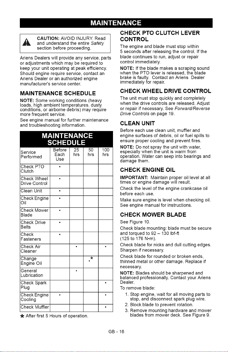
MAINTENANCE SCHEDULE
NOTE: Some working conditions (heavy
loads, high ambient temperatures, dusty
conditions, or airborne debris) may require
more frequent service.
See engine manual for further maintenance
and troubleshooting information.
Service
Performed
Check PTO
Clutch
Check Wheel
Drive Control
Clean Unit
Check Engine
Oil
Check Mower
Blade
Check Drive
Belts
Check
Fasteners
Check Air
Cleaner
Change *
Engine Oil
General
Lubrication
Check Spark
Plug
Check Engine
Cooling
Check Muffler
After first 5 Hours of operation.
CHECK PTO CLUTCH LEVER
CONTROL
The engine and blade must stop within
5 seconds after releasing the control. If the
blade continues to run, adjust or repair
control immediately.
NOTE: If the blade makes a scraping sound
when the PTO lever is released, the blade
brake is faulty. Contact an Ariens Dealer
immediately for repair.
CHECK WHEEL DRIVE CONTROL
The unit must stop quickly and completely
when the drive controls are released. Adjust
or repair if necessary. See Forward/Reverse
Drive Controls on page 19.
CLEAN UNIT
Before each use clean unit, muffler and
engine surfaces of debris, oil or fuel spills to
ensure proper cooling and prevent fires.
NOTE: Do not spray the unit with water,
especially when the unit is warm from
operation. Water can seep into bearings and
damage them.
CHECK ENGINE OIL
IMPORTANT: Maintain proper oil level at all
times or engine damage will result.
Check the level of the engine crankcase oil
before each use.
Make sure engine is level when checking oil.
See engine manual for instructions.
CHECK MOWER BLADE
See Figure 10.
Check blade mounting: blade must be secure
and torqued to 92 - 130 Ibf-ft
(125 to 176 N.m).
Check blade for nicks and dull cutting edges.
Sharpen if necessary.
Check blade for rounded or broken ends,
thinned metal or other damage. Replace if
necessary.
NOTE: Blades should be sharpened and
balanced professionally. Contact your Ariens
Dealer.
To remove blade:
1. Stop engine, wait for all moving parts to
stop, and disconnect spark plug wire.
2. Block blade to prevent rotation.
3. Remove mounting hardware and mower
blades from mower deck. See Figure 9.
GB - 16
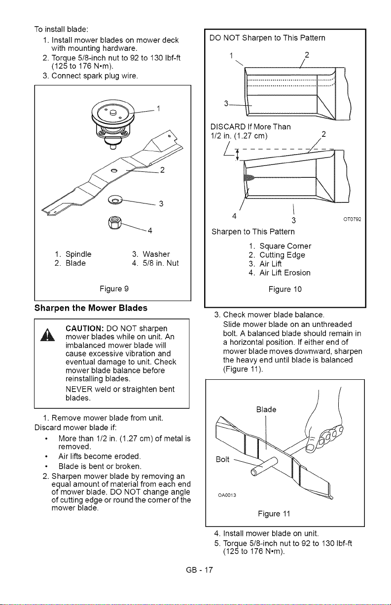
Toinstallblade:
1.Installmowerbladesonmowerdeck
withmountinghardware.
2.Torque5/8-inchnutto92to130Ibf-ft
(125to176N°m).
3.Connectsparkplugwire.
1.Spindle 3.Washer
2.Blade 4.5/8in.Nut
Figure9
Sharpen the Mower Blades
CAUTION: DO NOT sharpen
mower blades while on unit. An
imbalanced mower blade will
cause excessive vibration and
eventual damage to unit. Check
mower blade balance before
reinstalling blades.
NEVER weld or straighten bent
blades.
1. Remove mower blade from unit.
Discard mower blade if:
More than 1/2 in. (1.27 cm) of metal is
removed.
Air lifts become eroded.
Blade is bent or broken.
2. Sharpen mower blade by removing an
equal amount of material from each end
of mower blade. DO NOT change angle
of cutting edge or round the corner of the
mower blade.
DO NOT Sharpen to This Pattern
1 2
\ /
:::::::::::::::::::::::::::::::::::
DISCARD If More Than
1/2 in. (1.27 cm) 2
4
3 OT0792
Sharpen to This Pattern
1. Square Corner
2. Cutting Edge
3. Air Lift
4. Air Lift Erosion
Figure 10
3. Check mower blade balance.
Slide mower blade on an unthreaded
bolt. A balanced blade should remain in
a horizontal position. If either end of
mower blade moves downward, sharpen
the heavy end until blade is balanced
(Figure 11).
Blade
Bolt
Figure 11
4. Install mower blade on unit.
5. Torque 5/8-inch nut to 92 to 130 Ibf-ft
(125 to 176 N°m).
GB - 17
CHECK DRIVE BELTS
Check drive belts and replace if worn or
damaged. See Wheel Drive Belts on page 20.
CHECK FASTENERS
Check all fasteners for proper tightness. Pay
special attention to blade hardware and all
guards, shields and safety devices.
CHECK AIR CLEANER
See engine manual for specific information.
CHANGE ENGINE OIL
IMPORTANT: Change engine crankcase oil
after first five (5) hours of operation. Then
change oil after every 25 hours of operation.
Refer to engine manual for instructions and
proper oil type.
IMPORTANT: Proper oil level must be
maintained at all times or engine damage will
result. DO NOT overfill. Be sure engine is
level when adding oil.
GENERAL LUBRICATION
The unit has sealed maintenance-free
spindles and transmission. The unit should
not require lubrication except for light oil or
grease at pivot points.
CHECK SPARK PLUG
Spark plug should be replaced every 100
hours of operation or each year.
NOTE: Loose spark plug wire terminals can
cause sparking. Replace terminal if
damaged.
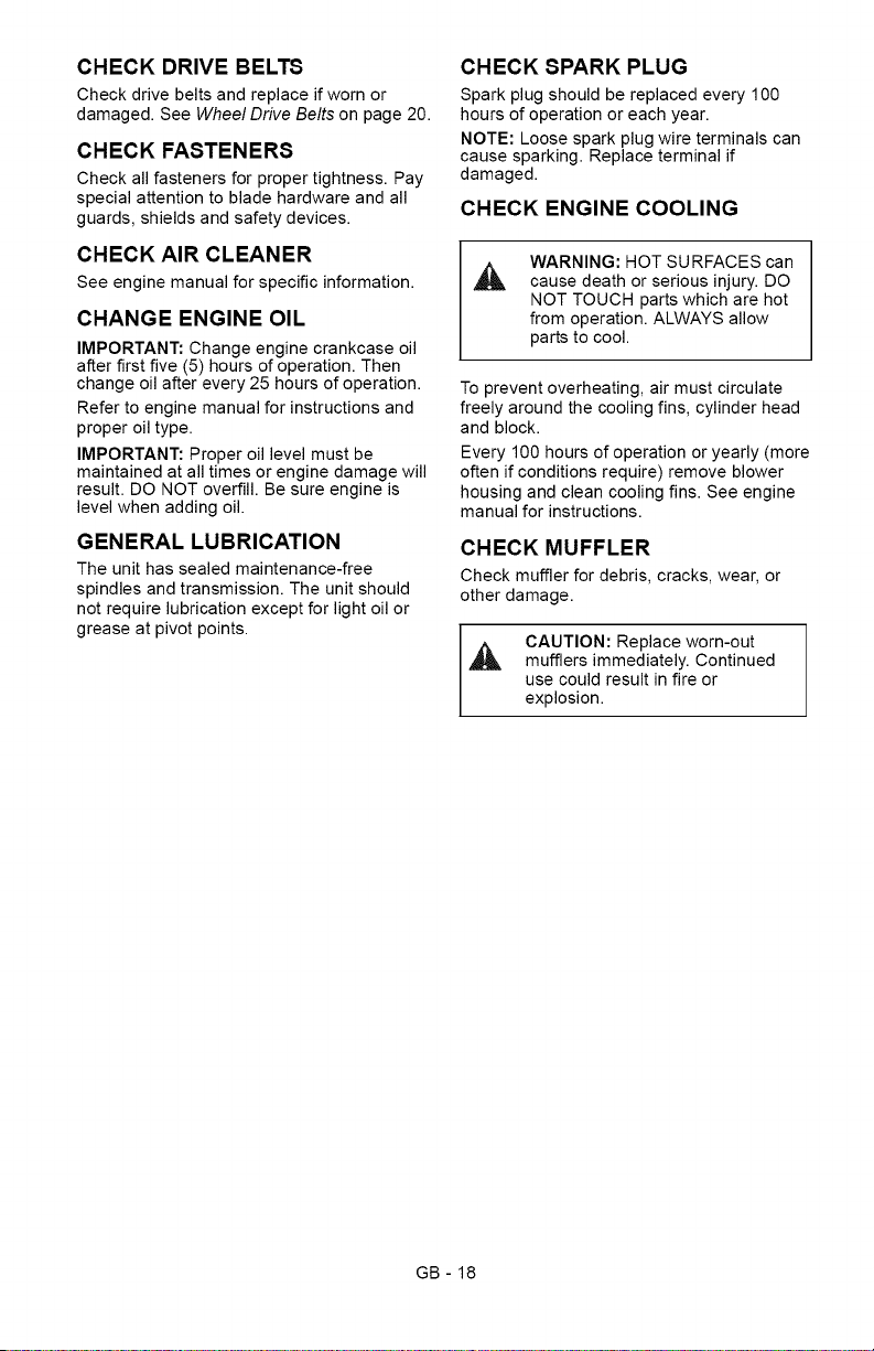
CHECK ENGINE COOLING
,&
WARNING: HOT SURFACES can
cause death or serious injury. DO
NOT TOUCH parts which are hot
from operation. ALWAYS allow
parts to cool.
To prevent overheating, air must circulate
freely around the cooling fins, cylinder head
and block.
Every 100 hours of operation or yearly (more
often if conditions require) remove blower
housing and clean cooling fins. See engine
manual for instructions.
CHECK MUFFLER
Check muffler for debris, cracks, wear, or
other damage.
CAUTION: Replace worn-out
,_ mufflers immediately. Continued
use could result in fire or
explosion.
GB - 18
_o_l V_4_I m]V_4m_ll_l / _vj1:1_III__]
,_ CAUTION: AVOID INJURY. Read
and understand the entire Safety
section before proceeding.
PTO CLUTCH
WARNING: If you cannot adjust
the controls so the unit drives
properly, immediately take the unit
to your local authorized dealer for
repairs.
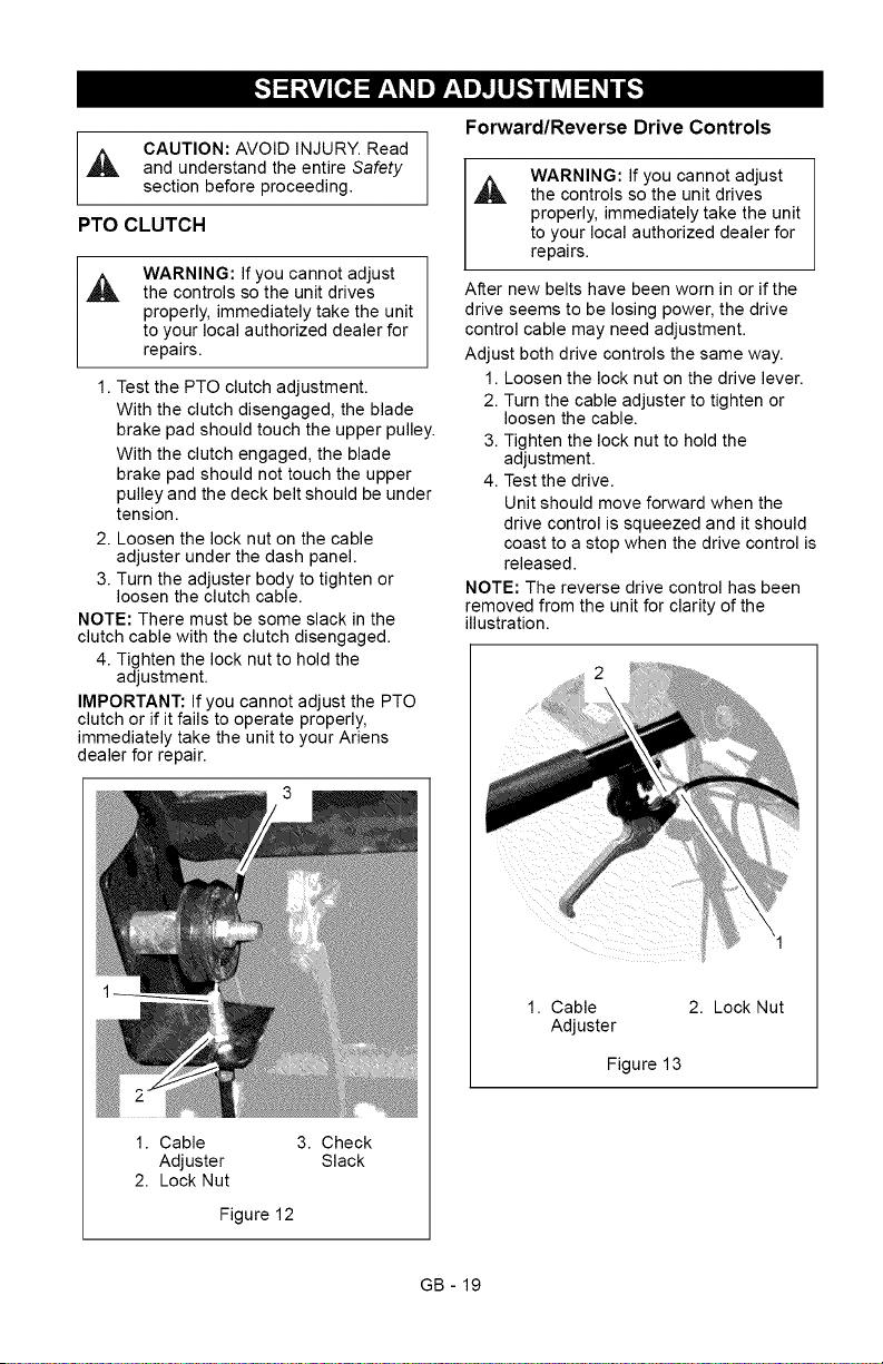
1. Test the PTO clutch adjustment.
With the clutch disengaged, the blade
brake pad should touch the upper pulley.
With the clutch engaged, the blade
brake pad should not touch the upper
pulley and the deck belt should be under
tension.
2. Loosen the lock nut on the cable
adjuster under the dash panel.
3. Turn the adjuster body to tighten or
loosen the clutch cable.
NOTE: There must be some slack in the
clutch cable with the clutch disengaged.
4. Tighten the lock nut to hold the
adjustment.
IMPORTANT: If you cannot adjust the PTO
clutch or if it fails to operate properly,
immediately take the unit to your Ariens
dealer for repair.
1. Cable 3. Check
Adjuster Slack
2. Lock Nut
Figure 12
Forward/Reverse Drive Controls
WARNING: If you cannot adjust
the controls so the unit drives
properly, immediately take the unit
to your local authorized dealer for
repairs.
After new belts have been worn in or if the
drive seems to be losing power, the drive
control cable may need adjustment.
Adjust both drive controls the same way.
1. Loosen the lock nut on the drive lever.
2. Turn the cable adjuster to tighten or
loosen the cable.
3. Tighten the lock nut to hold the
adjustment.
4. Test the drive.
Unit should move forward when the
drive control is squeezed and it should
coast to a stop when the drive control is
released.
NOTE: The reverse drive control has been
removed from the unit for clarity of the
illustration.
1. Cable
Adjuster
2. Lock Nut
Figure 13
GB - 19
BELT REPLACEMENT
WARNING: AVOID INJURY.
ALWAYS block wheels, engage
parking brake and know all jack
stands are strong, secure and will
hold weight of unit during
maintenance.
Wheel Drive Belts
1. Stop engine, remove key, wait for all
moving parts to stop and hot parts to
cool.
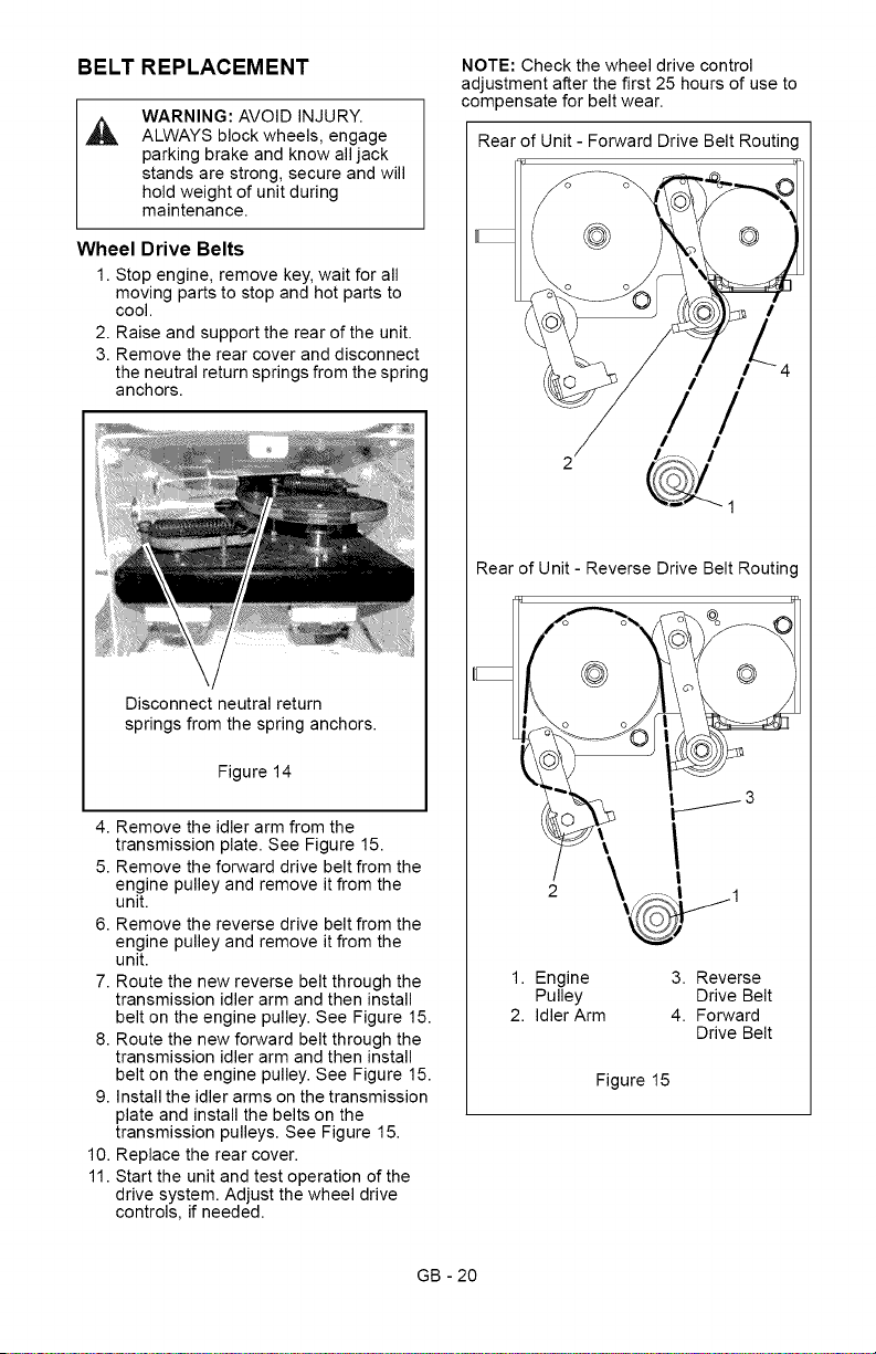
2. Raise and support the rear of the unit.
3. Remove the rear cover and disconnect
the neutral return springs from the spring
anchors.
Disconnect neutral return
springs from the spring anchors.
Figure 14
4. Remove the idler arm from the
transmission plate. See Figure 15.
5. Remove the forward drive belt from the
engine pulley and remove it from the
unit.
6. Remove the reverse drive belt from the
engine pulley and remove it from the
unit.
7. Route the new reverse belt through the
transmission idler arm and then install
belt on the engine pulley. See Figure 15.
8. Route the new forward belt through the
transmission idler arm and then install
belt on the engine pulley. See Figure 15.
9. Install the idler arms on the transmission
plate and install the belts on the
transmission pulleys. See Figure 15.
10. Replace the rear cover.
11. Start the unit and test operation of the
drive system. Adjust the wheel drive
controls, if needed.
NOTE: Check the wheel drive control
adjustment after the first 25 hours of use to
compensate for belt wear.
Rear of Unit - Forward Drive Belt Routing
I
I I
/
I I
Rear of Unit - Reverse Drive Belt Routing
1
1. Engine 3. Reverse
Pulley Drive Belt
2. Idler Arm 4. Forward
Drive Belt
Figure 15
GB - 20
PTO Belt
1. Stop engine, remove key, wait for all
moving parts to stop and hot parts to
cool.
2. Remove the two drive belts from engine
pulley. See Wheel Drive Belts on
page 20.
3. Remove the belt cover from the deck.
4. Disconnect the two idler springs from the
spring anchors.
NOTE: Do not remove the bolt holding the
engine pulley to the crankshaft. Loosen it
enough so the PTO belt clears the belt finger.
5. Loosen the bolt holding the engine
pulley to the crankshaft and slide the
pulley down until the PTO belt can be
removed from the pulley.
6. Install the new belt on the engine pulley
and on the deck pulleys.
7. Push the engine pulley up the crankshaft
and tighten the mounting bolt to 55 Ibf-ft
(74.5 a,m).
8. Connect the two idler springs to spring
anchors.
9. Replace the belt cover.
10. Replace the wheel two drive belts on the
engine pulley.
Rear of Unit
2
1. PTO Belt
2. Engine Pulley
3. Idler Arm
6
3
4
4. Tension
Spring
5. Spring Anchor
6. Deck Belt
Figure 16
Deck Belt
1. Stop engine, remove key, wait for all
moving parts to stop and hot parts to
cool.
2. Remove the two drive belts from engine
pulley. See Wheel Drive Belts on
page 20.
3. Remove the PTO belt from the PTO
clutch. See PTO Belt on page 21.
4. Remove the two idler arms from the
deck.
5. Remove the deck belt and install the
new belt.
6. Replace the two idler arms on the deck.
7. Replace the PTO belt on the PTO clutch.
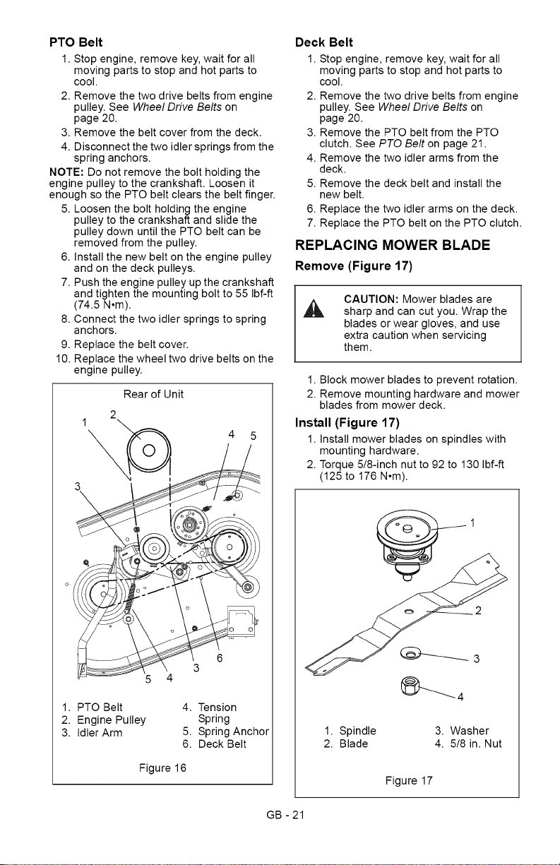
REPLACING MOWER BLADE
Remove (Figure 17)
CAUTION: Mower blades are
sharp and can cut you. Wrap the
blades or wear gloves, and use
extra caution when servicing
them.
1. Block mower blades to prevent rotation.
2. Remove mounting hardware and mower
blades from mower deck.
Install (Figure 17)
1. Install mower blades on spindles with
mounting hardware.
2. Torque 5/8-inch nut to 92 to 130 Ibf-ft
(125 to 176 N°m).
1. Spindle 3. Washer
2. Blade 4. 5/8 in. Nut
Figure 17
GB - 21
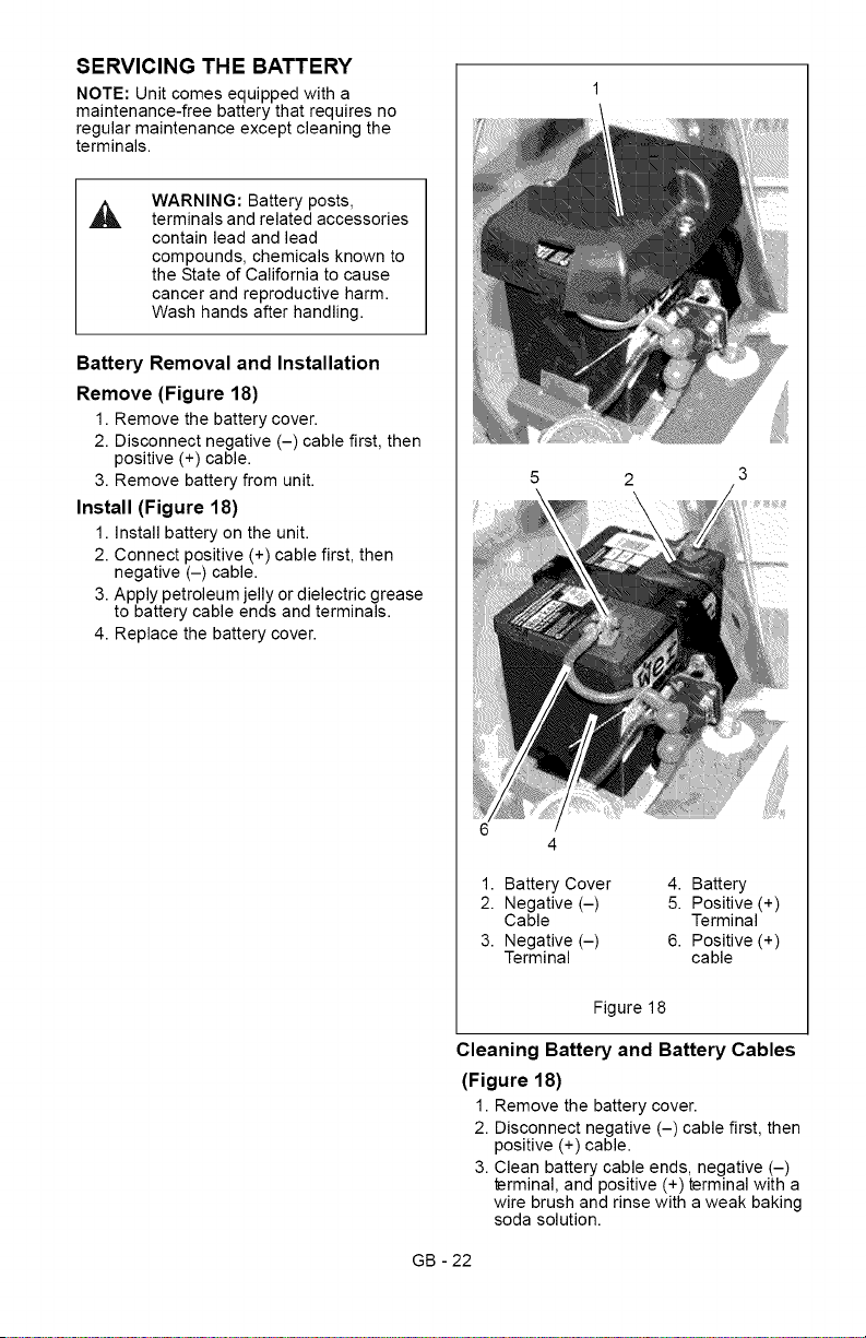
SERVICING THE BATTERY
NOTE: Unit comes equipped with a
maintenance-free battery that requires no
regular maintenance except cleaning the
terminals.
,&
WARNING: Battery posts,
terminals and related accessories
contain lead and lead
compounds, chemicals known to
the State of California to cause
cancer and reproductive harm.
Wash hands after handling.
Battery Removal and Installation
Remove (Figure 18)
1. Remove the battery cover.
2. Disconnect negative (-) cable first, then
positive (+) cable.
3. Remove battery from unit.
Install (Figure 18)
1. Install battery on the unit.
2. Connect positive (+) cable first, then
negative (-) cable.
3. Apply petroleum jelly or dielectric grease
to battery cable ends and terminals.
4. Replace the battery cover.
1. Battery Cover
2. Negative (-)
Cable
3. Negative (-)
Terminal
4. Battery
5. Positive (+)
Terminal
6. Positive (+)
cable
Figure 18
Cleaning Battery and Battery Cables
(Figure 18)
1. Remove the battery cover.
2. Disconnect negative (-) cable first, then
positive (+) cable.
3. Clean battery cable ends, negative (-)
_erminal, and positive (+) terminal with a
wire brush and rinse with a weak baking
soda solution.
GB - 22
4.Connectpositive(+)cablefirst,then
negative(-)cable.
5.Applypetroleumjellyordielectricgrease
tobatterycableendsandterminals.
6.Replacebeltcover.
Charging the Battery
A
WARNING: FROZEN
BATTERIES CAN EXPLODE
and result in death or serious
injury. DO NOT charge a frozen
battery. Let the battery thaw
before charging.
Follow First Aid directions for contact with
battery fluid.
External Contact: Flush with water.
Eyes: Flush with water for at least 15
minutes and get medical attention
immediately!
Internal Contact: Drink large quantities
of water. Follow with Milk of Magnesia,
beaten egg or vegetable oil. Get
medical attention immediately!
In case of internal contact, DO NOT
induce vomiting!
IMPORTANT: DO NOT fast charge. Charging
at a higher rate will damage or destroy
battery.
IMPORTANT: ALWAYS follow information
provided on battery and battery charger.
Contact battery and battery charger
manufacturers' for detailed instructions.
1. Remove battery from unit (see Battery
Removal and Installation on page 22).
2. Place battery in a well-ventilated area.
3. Connect positive (+) lead of charger to
positive (+) _rminal, and negative (-)
lead of charger to negative (-) terminal.
4. Charge battery according to battery
charger and battery manufacturers'
instructions.
5. Install battery on unit (see Battery
Removal and Installation on page 22).
Jump-Starting
Ariens does not recommend jump-starting
your unit. Jump-starting can damage engine
and electrical system components. See your
engine manual for more detailed information.
CAUTION: AVOID INJURY. Read
_i_ and understand the entire Safety
section before proceeding.
IMPORTANT: NEVER spray unit with high-
pressure water or store unit outdoors. Store
mower in a cool, dry, protected location.
Cleaning
NOTE: Allow unit to cool before cleaning.
Clean unit thoroughly with mild soap and low
pressure water. Brush off dirt and debris from
all surfaces. Touch up all scratched surfaces
to prevent rust. Matching touch-up paint is
available from your Ariens Dealer. Do not use
abrasives, solvents, or harsh cleaners.
Inspection
Inspect mower and repair or replace worn or
damaged parts to avoid delays when
beginning use again.
Regularly check all hardware and keep
fasteners tight. Know unit is in safe working
condition.
Grass Bag
Wash out grass bag and allow to dry before
storage. Grass bag may be stored in position
on mower.
Engine
When storing unit for extended periods of
time, remove all fuel from tank and carburetor
(run dry). Refer to engine manual.
Fuel System
Gasoline left in the fuel system for extended
periods without a stabilizer will deteriorate,
resulting in gum deposits in the system.
These deposits can damage the carburetor
and the fuel hoses, filter and tank. Prevent
deposits from forming in the fuel system
during storage by adding a quality fuel
stabilizer to the fuel. Follow the
recommended mix ratio found on the fuel
stabilizer container.
To treat the fuel system for storage:
1. Add fuel stabilizer according to
manufacturer's instructions.
2. Run engine for at least 10 minutes after
adding stabilizer to allow it to reach the
carburetor.
NEVER store the engine with fuel in the fuel
tank inside of a building with potential
sources of ignition.
GB - 23

/ | _Toll]_'_[oIo)_
PROBLEM
Engine will not
start
Engine is
difficult to
restart
PROBABLE CAUSE CORRECTION
1. Safety switch not held down. 1.
2,
3.
4.
5,
6.
7.
1. Out of fuel.
Ignition switch is faulty. 2.
Wiring harness fuse is blown. 3.
Loose or corroded battery 4.
cables.
Discharged battery. 5.
Faulty starter. 6.
Fuel tank empty. 7.
1.
Fuel filter is dirty. 2.
Faulty spark plug. 3.
Air cleaner is plugged or dirty. 4.
Faulty engine. 5.
Deck is clogged with grass. 1.
Blades are dull. 2.
Cutting wet grass. 3.
Cutting too low. 4.
PTO belt is slipping. 5.
Deck is clogged with grass. 1.
Blades are dull. 2.
Cutting wet grass. 3.
Cutting too low. 4.
Deck is clogged with grass. 1.
Blades are dull. 2.
Cutting wet grass. 3.
Cutting too low. 4.
PTO belt is slipping. 5.
Loose or damaged drive belts. 1.
Damaged drive cable. 2.
Damaged transmission or 3.
drive component.
2,
3.
4.
5.
Cut is poor 1.
2.
3.
4.
5.
Grass does 1.
not disperse
evenly 2.
3.
4.
Mower does 1.
not bag
clippings 2.
3.
4.
5.
Wheel drive 1.
does not
engage 2.
3.
Hold down safety switch
while turning the ignition key.
Replace ignition switch.
Replace fuse.
Clean and tighten battery
cables.
Charge the battery.
See your Dealer.
Fill fuel tank.
Fill fuel tank with clean, fresh
fuel.
Replace fuel filter.
Replace spark plug.
Clean or replace air cleaner.
Refer to the engine manual
or see your Dealer.
Clean the deck cutting
chamber.
Sharpen or replace blades.
Wait for grass to dry.
Raise cutting height and cut
grass in two or more passes.
Adjust or replace PTO belt.
Clean the deck cutting
chamber.
Sharpen or replace blades.
Wait for grass to dry.
Raise cutting height and cut
grass in two or more passes.
Clean the deck cutting
chamber.
Sharpen or replace blades.
Wait for grass to dry.
Raise cutting height and cut
grass in two or more passes.
Adjust or replace PTO belt.
Adjust or replace drive belts.
See Wheel Drive Belts on
page 20.
Replace drive cable. See
your authorized dealer for
repairs.
See your authorized dealer
for repairs.
GB - 24

P_'T__o];_[_,,,,_
Always use genuine Ariens parts to keep
tour mower running like new.
Part Description
Number
03746500 Blade
03797300 Mulching Blade
07200529 Forward Traction Belt
07200506 Reverse Traction Belt
07243300 PTO Belt
07234300 Deck Belt
21534100 Spark Plug
See your authorized Ariens Dealer to add
these optional accessories.
71106100 Bagger Kit
71510800 Mulch Kit
GB - 25
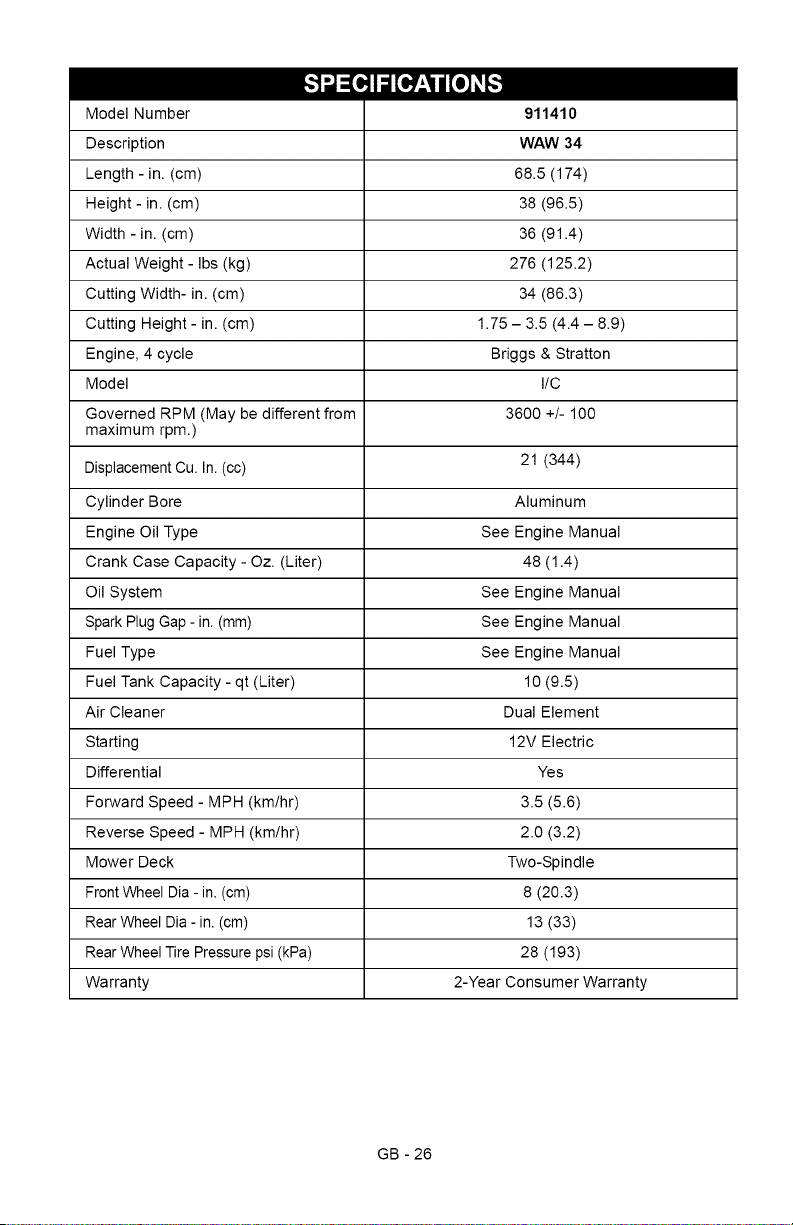
___o_,,,_
Model Number
Description
Length - in. (cm)
Height - in. (cm)
Width - in. (cm)
Actual Weight - Ibs (kg)
Cutting Width- in. (cm)
Cutting Height- in. (cm)
Engine, 4 cycle
Model
Governed RPM (May be different from
maximum rpm.)
Displacement Cu. In. (cc)
Cylinder Bore
Engine Oil Type
Crank Case Capacity - Oz. (Liter)
Oil System
Spark Plug Gap - in. (mm)
Fuel Type
Fuel Tank Capacity - qt (Liter)
Air Cleaner
Starting
Differential
Forward Speed - MPH (km/hr)
Reverse Speed - MPH (km/hr)
Mower Deck
Front Wheel Dia - in. (cm)
Rear Wheel Dia - in. (cm)
Rear Wheel Tire Pressure psi (kPa)
Warranty
911410
WAW 34
68.5 (174)
38 (96.5)
36 (91.4)
276 (125.2)
34 (86.3)
1.75 - 3.5 (4.4 - 8.9)
Briggs & Stratton
I/C
3600 +/- 100
21 (344)
Aluminum
See Engine Manual
48 (1.4)
See Engine Manual
See Engine Manual
See Engine Manual
10 (9.5)
Dual Element
12V Electric
Yes
3.5 (5.6)
2.0 (3.2)
Two-Spindle
8 (20.3)
13 (33)
28 (193)
2-Year Consumer Warranty
GB - 26

Two-Year Limited Lawn
and Garden Warranty
This warranty statement applies only to 21-Inch Walk Behind Lawn Mowers, Wide Area
Walks, AMP Wide Area Walks, Tillers, String Trimmers, Log Splitters, Edgers and Power
Brushes
Ariens Company (Ariens) warrants to the original purchaser that Ariens and Gravely brand consumer
products manufactured and sold by Ariens will be free from defects in material and workmanship for a period
of two years after the date of purchase. An authorized Ariens dealer (Ariens brand products) or Gravely
dealer (Gravely brand products) will repair any defect in material or workmanship, and repair or replace any
defective part, subject to the conditions, limitations and exclusions set forth herein. Such repair or
replacement will be free of charge (labor and parts) to the original purchaser except as noted below.
Two-Year Limited Warranty on AMP TM Series Battery Packs and Subassembfies
The battery pack and/or battery subassemblies on AMP series electric mowers is/are warranted to the
original purchaser for two years from the date of purchase. Ariens will replace, free of charge to the
original purchaser, any battery pack and/or battery subassembly that fails due to defect in material or
workmanship for one year after the date of purchase. For the next 12 months, Ariens will cover the pro-
rated cost of replacing a battery pack and/or battery subassembly that fails due to defect in material or
workmanship. This warranty does not apply to battery packs or battery subassemblies that fail due to
accident, neglect, abuse, improper maintenance, improper storage or improper charging procedures.
One-Year Limited Warranty on Professional/Commercial 21-inch Walk-Behind Lawn
Mowers
21-inch walk-behind lawn mowers labeled or designated by Ariens as a Professional/Commercial prod-
uct put to any business use, agricultural, commercial, or industrial, are warranted to the original pur-
chaser to be free from defects in material and workmanship for a period of one year after the date of
purchase.
90-Day Limited Warranty on Service Parts and Accessories
Genuine Ariens or Gravely brand service parts and accessories are warranted to be free from defects
in material and workmanship for a period of 90 days after the date of purchase. An authorized Ariens or
Gravely dealer will repair or replace any such part or accessory free of charge, except for labor, during
that period.
Except for 21-inch walk-behind lawn mowers labeled or designated by Ariens as a Professional/Commercial
product, the duration of all warranties herein applies only if the product is put to personal use around a
household or residence. If the product is put to any business use, agricultural, commercial, or industrial, then
the duration of these warranties shall be 90 days after the date of purchase. If any product is rented or
leased, then the duration of these warranties shall be 90 days after the date of purchase.
Exceptions, Limitations, Exclusions
Customer Responsibilities
Register the product immediately at the time of sale. If the dealer does not register the product, the
customer must complete the product registration card in the literature package and return it to the Ariens
Company, or register the unit online at www.ariens.com or www.gravely.com.
To obtain warranty service, the original purchaser must:
Perform the maintenance and minor adjustments explained in the owner's manual.
Promptly notify Ariens or an authorized Ariens or Gravely service representative of the need for
warranty service.
Transport the product to and from the place of warranty service.
Have the warranty service performed by an authorized Ariens or Gravely service representative.
ARIENS COMPANY
GRAVELY® I STENSC_ I LQCKEC_ I NATtQNAL® I BYNORM(_ I EVERRIDEC_ I GREAT DANE c_ Con L&G 2010
27
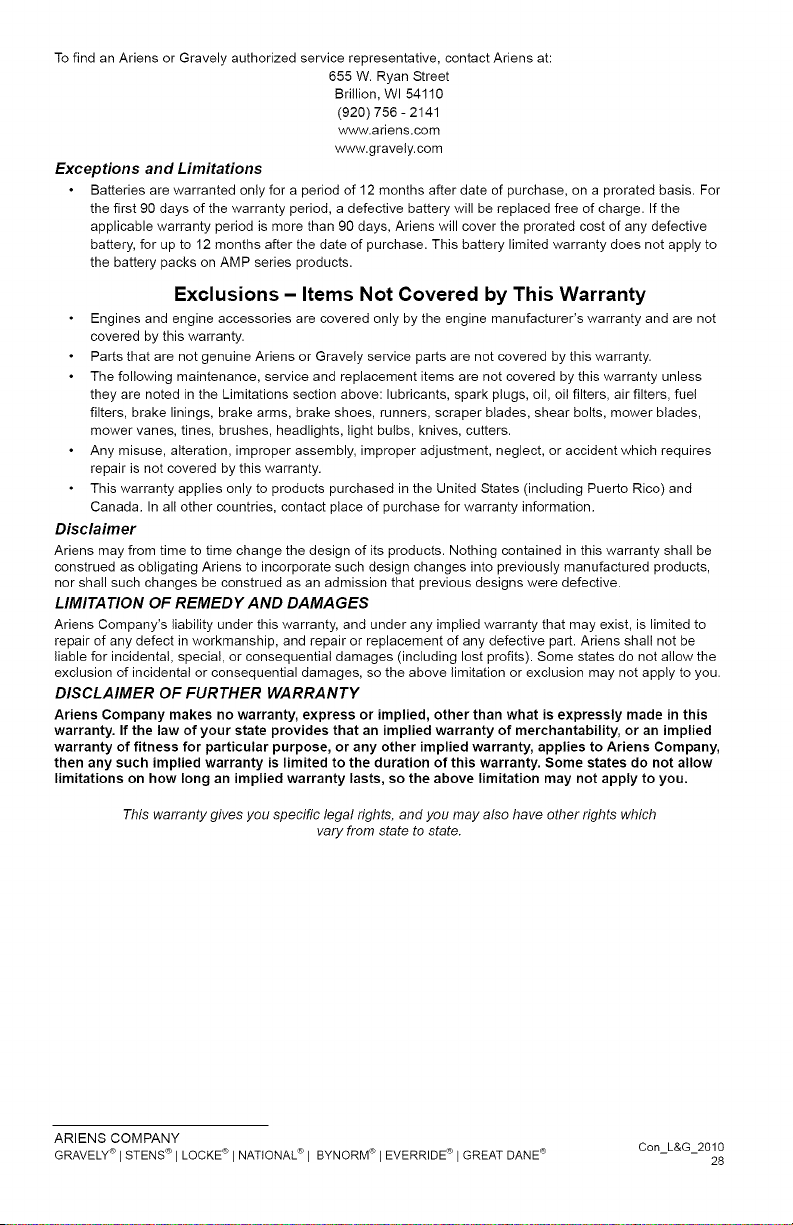
To find an Ariens or Gravely authorized service representative, contact Ariens at:
655 W. Ryan Street
Brillion, WI 54110
(920) 756- 2141
www.ariens.com
www.gravely.com
Exceptions and Limitations
Batteries are warranted only for a period of 12 months after date of purchase, on a prorated basis. For
the first 90 days of the warranty period, a defective battery will be replaced free of charge. If the
applicable warranty period is more than 90 days, Ariens will cover the prorated cost of any defective
battery, for up to 12 months after the date of purchase. This battery limited warranty does not apply to
the battery packs on AMP series products.
Exclusions - Items Not Covered by This Warranty
Engines and engine accessories are covered only by the engine manufacturer's warranty and are not
covered by this warranty.
Parts that are not genuine Ariens or Gravely service parts are not covered by this warranty.
The following maintenance, service and replacement items are not covered by this warranty unless
they are noted in the Limitations section above: lubricants, spark plugs, oil, oil filters, air filters, fuel
filters, brake linings, brake arms, brake shoes, runners, scraper blades, shear bolts, mower blades,
mower vanes, tines, brushes, headlights, light bulbs, knives, cutters.
Any misuse, alteration, improper assembly, improper adjustment, neglect, or accident which requires
repair is not covered by this warranty.
This warranty applies only to products purchased in the United States (including Puerto Rico) and
Canada. In all other countries, contact place of purchase for warranty information.
Disclaimer
Ariens may from time to time change the design of its products. Nothing contained in this warranty shall be
construed as obligating Ariens to incorporate such design changes into previously manufactured products,
nor shall such changes be construed as an admission that previous designs were defective.
LIMITATION OF REMEDY AND DAMAGES
Ariens Company's liability under this warranty, and under any implied warranty that may exist, is limited to
repair of any defect in workmanship, and repair or replacement of any defective part. Ariens shall not be
liable for incidental, special, or consequential damages (including lost profits). Some states do not allow the
exclusion of incidental or consequential damages, so the above limitation or exclusion may not apply to you.
DISCLAIMER OF FURTHER WARRANTY
Ariens Company makes no warranty, express or implied, other than what is expressly made in this
warranty. If the law of your state provides that an implied warranty of merchantability, or an implied
warranty of fitness for particular purpose, or any other implied warranty, applies to Ariens Company,
then any such implied warranty is limited to the duration of this warranty. Some states do not allow
limitations on how long an implied warranty lasts, so the above limitation may not apply to you.
This warranty gives you specific legal rights, and you may also have other rights which
vary from state to state.
ARIENS COMPANY
GRAVELY® I STENSC_ I LOCKEC_ I NATIONAL® I BYNORM_ I EVERRIDEC_ I GREAT DANE c_ Con L&G 2010
28

Ariens Company
655 West Ryan Street
Brillion, WI 54110-1072
920-756-2141
Fax 920-756-2407
www.ariens.com
A WARNING A
The engine exhaust from this product
contains chemicals known to the State
of California to cause cancer, birth
defects or other reproductive harm.

Wide Area Walk Mower
Manual del propietario/operador
Models
911410 - WAW 34
_ _ (_ ESPA_OL
01325602 2/10
Printedin USA
I1Eqi][_"
Seguridad ........................ 4
Montaje ......................... 10
Controles y caracteristicas ........ 12
Funcionamiento .................. 13
Mantenimiento ................... 17
Reparaciones y ajustes ........... 21
Almacenamiento ................. 27
Localizaci6n de averias ........... 28
Piezas de repuesto ............... 29
Accesorios ...................... 29
Especificaciones ................. 30
Garantia ........................ 33
limb/ _,_o_]_l
NON-ENGLISH MANUALS
Manuals in languages other
,_ than English may be obtained
from your Dealer. Visit your dealer
or www.ariens.com for a list of
_--_ languages available for your
equipment.
Manuals printed in languages
other than English are also
available as a free download
on our website:
http://www.ariens.com
MANUALES EN IDIOMAS
DIFERENTES DEL INGLES
Puede obtener manuales
,_ en idiomas diferentes del inglesen su distribuidor. Visite a su
distribuidor o vaya a www.ariens.com
para obtener una lista de idiomas
disponibles para su equipo.
Tambien puede imprimir manuales
en idiomas diferentes del ingles
descargandolos gratuitamente de
nuestra pagina Web:
http://www.ariens.com
MANUELS NON ANGLAIS
Des manuels dans diff@entes
,_ langues sont disponibles chezvotre revendeur. Rendez-vous
chez votre revendeur ou allez
sur le site www.ariens.com pour
consulter la liste des langues
disponibles pour votre equipement.
Les manuels imprimes dans des
langues diff@entes de I'anglais
sont egalement disponibles en
telechargement gratuit sur notre
site Web :
http://www.ariens.com
EL MANUAL
Antes de utilizar la unidad, lea con atenci6n
yen su totalidad los manuales. El contenido
de los manuales le ayudara a entender
las instrucciones y los controles durante
el funcionamiento normal y el mantenimiento.
Todas las referencias a la izquierda, derecha,
delante o detras se dan desde la posici6n
del operador, orientado en la direcci6n
de marcha adelante.
MANTENIMIENTO Y PIEZAS
DE REPUESTO
AI pedir piezas de repuesto o al realizar
preguntas sobre reparaciones, tenga a mano
los nQmeros de modelo y de serie de la unidad
y del motor.
Los nQmeros estan situados en el formulario
de registro del producto del paquete
de documentaci6n de la unidad. Tambien
se hallan impresos en una etiqueta de nQmero
de serie, Iocalizada en la estructura de la unidad
(Figura 1).
Etiqueta del nQmero de
serie de la unidad
Figura 1
E-2
•AnoteaquilosnQmerosdemodelo
ydeseriedelaunidad:
l
• Anote aqui los nQmeros de modelo
y de serJe del motor:
t
REGISTRO DEL PRODUCTO
El concesionario Ariens debera registrar el
producto en el momento de la compra. El
registro del producto ayudara a la compa_ia
a procesar las reclamaciones de garantia, asi
como a ponerse en contacto con usted con la
informaci6n de servicio mas reciente. Todas
las reclamaciones que cumplan los requisitos
durante el periodo de garantia limitada seran
aceptadas, independientemente de si se
devuelve o no la tarjeta de registro de
producto. Guarde una prueba de su compra si
no registra su unidad.
Nota para el cliente: Si el Concesionario no
registra el producto, rellene, firme y devuelva
la tarjeta de registro del producto a Ariens
o vaya a www.ariens.com en Intemet.
]
J
PIEZA8 DE REPUESTO
NO AUTORIZADAS
Utilice Qnicamente piezas de repuesto
de Ariens. La sustituci6n de cualquier pieza
de este vehiculo por otra que no sea una
pieza de repuesto autorizada por Ariens
puede afectar negativamente al rendimiento,
la durabilidad o la seguridad de la unidad,
y puede Ilegar a anular la garantia. Ariens
declina toda responsabilidad por daSos
o reclamaciones, ya sea a la garantia,
daSos materiales, lesiones o incluso la muerte,
provocados por el uso de piezas de repuesto
no autorizadas. Para Iocalizar su distribuidor
Ariens mas cercano, acuda a www.ariens.com
en Intemet.
ENTREGA DEL CONCESIONARIO
El concesionario debe:
1. Verificar que el montaje y todos
los ajustes se hayan realizado
adecuadamente.
2. Rellenar la tarjeta de registro
del comprador original y enviarla
de vuelta a Ariens.
3. Explicar la politica de garantia limitada
de Ariens.
4. Explicar la lubricaci6n y el mantenimiento
recomendado. Asesorar al cliente sobre
los ajustes. Recordar al cliente que cambie
el aceite del carter del motor 4 ciclos
tras las primeras cinco (5) horas de
funcionamiento.
5. Explicar al cliente los controles
y el funcionamiento de la unidad.
Asesorar al cliente sobre los ajustes.
Comentarle e insistirle sobre las
reglas de seguridad. Proporcionarle
los Manuales del propietario/operador,
piezas de repuesto y del motor.
Aconsejarle que los lea atentamente
y los entienda.
CL.&.USULA DE EXENCION
DE RESPONSABILIDAD
Ariens se reserva el derecho de abandonar la
fabricaci6n, realizar cambios y mejoras a sus
productos en cualquier momento, sin previo
aviso u obligaci6n. Las descripciones y
especificaciones contenidas en este manual
eran las vigentes en el momento de su
publicaci6n. Algunos equipamientos
descritos en este manual pueden ser
opcionales. Algunas ilustraciones pueden no
ser de aplicaci6n a su unidad.
E-3
iADVERTENClA7Estamaquina
decortepuedeamputarmanosy
piesylanzarobjetos.Sinoobserva
lasinstruccionesdeseguridadde
losmanualesylascalcomanias
podrianproducirselesiones
gravesoinclusolamuerte.
Laspendientessonunodelos
factoresprincipalesdeaccidentes
porresbalamientoycaida.Preste
especialatenciSncuandohaga
funcionarlaunidadenpendientes.
Sepuedenproduciraccidentes
tragicossieloperadornoobserva
lapresenciademenores.
Noasumanuncaquelosmenores
permaneceranenelQltimositio
enelquelosvio.
Lagasolinaesaltamente
inflamableysusvapores
sonexplosivos;manejela
concuidado.
Detengalaunidadyelmotor,
saquelaIlave(sicorresponde)
ydejequetodaslaspartesm6viles
sedetenganantesdeabandonar
laposiciSndeloperador.
S[MBOLOS DE 8EGURIDAD
Busque estos simbolos para
,_ informarse sobrelas precauciones
de seguridad importantes.
Su significado es el siguiente:
iAtencibn!
iAfecta a la seguridad
personal!
iEste alerta!
iObedezca el mensaje!
Los simbolos de alerta de seguridad
anteriores y las siguientes palabras se
usan en calcomanias yen este manual.
Lea y entienda todos los mensajes
de seguridad.
PELIGRO iSITUACIONDE PELIGRO INMINENTE!
Si no se evita, RESULTARA
en lesiones graves o la muerte.
iADVERTENCIA7 iSITUACION
POTENCIALMENTE PELIGROSA!
Si no se evita, PUEDE RESULTAR
en lesiones graves o la muerte.
,&
PRECAUCION: iSITUACION
POTENCIALMENTE PELIGROSA!
Si no se evita, PUEDE RESULTAR
en lesiones leves o moderadas.
Tambien puede usarse para alertar
contra practicas no seguras.
NOTACIONES
NOTA: Informaci6n de referencia general
para el funcionamiento y practicas
de mantenimiento correctos.
IMPORTANTE: Procedimientos o informaci6n
especificos requeridos para evitar dafios
a la unidad o al accesorio.
PRACTICA8 Y LEYES
Lleve a cabo con frecuencia y de manera
habitual precauciones de seguridad,
por su propio bien y por el de los demas.
Comprenda y obedezca todos los mensajes
de seguridad. Este alerta ante situaciones
inseguras y ante la posibilidad de lesiones
leves, moderadas o graves, o incluso la muerte.
Conozca las normas y leyes aplicables
en su regi6n.
FORMACION REQUERIDA
AL OPERADOR
El comprador original de esta unidad
ha sido instruido por el vendedor acerca
de su funcionamiento adecuado y seguro.
Si la unidad va a ser utilizada por otra persona
que no sea el comprador original, proporcione
SIEMPRE este manual y la formaci6n necesaria
referente a la seguridad antes de ponerla
en funcionamiento.
E-4
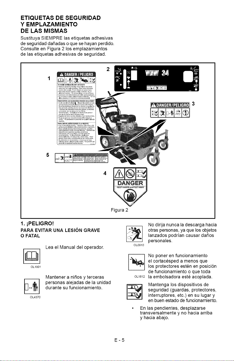
ETIQUETAS DE SEGURIDAD
Y EMPLAZAMIENTO
DE LAS MISMAS
Sustituya SIEMPRE las etiquetas adhesivas
de seguridad daSadas o que se hayan perdido.
Consulte en Figura 2 los emplazamientos
de las etiquetas adhesivas de seguridad.
5
Figura 2
1. iPELIGRO!
PARA EVITAR UNA LESION GRAVE
O FATAL
Lea el Manual del operador.
OL180I
©L4370
Mantener a niSos y terceras
personas alejadas de la unidad
durante su funcionamiento.
OL0910
No dirija nunca la descarga hacia
otras personas, ya que los objetos
lanzados podrian causar daSos
personales.
©L1812
No poner en funcionamiento
el cortacesped a menos que
los protectores esten en posici6n
de funcionamiento o que toda
la embolsadora este acoplada.
Mantenga los dispositivos de
seguridad (guardas, protectores,
interruptores, etc.) en su lugar y
en buen estado de funcionamiento.
En las pendientes, desplazarse
transversalmente y no hacia arriba
y hacia abajo.
E-5
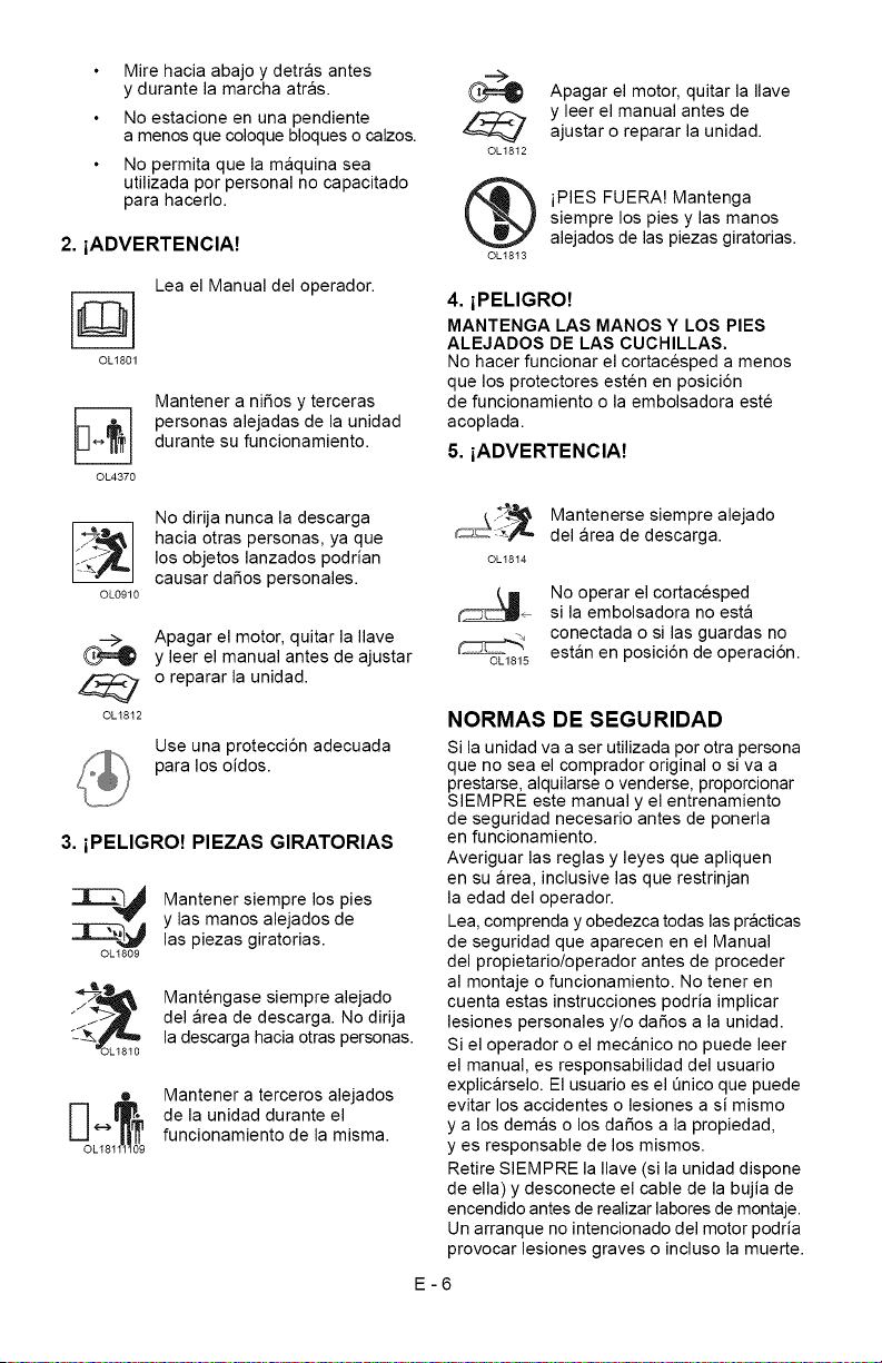
Mirehaciaabajoydetrasantes
ydurantelamarchaatras.
Noestacioneenunapendiente
amenosquecoloquebloquesocalzos.
Nopermitaquelamaquinasea
utilizadaporpersonalnocapacitado
parahacerlo.
2. iADVERTENCIA!
Lea el Manual del operador.
OL1801
OL4370
Mantener a niSos y terceras
personas alejadas de la unidad
durante su funcionamiento.
OL0910
No dirija nunca la descarga
hacia otras personas, ya que
los objetos lanzados podrian
causar daSos personales.
OLt812
Apagar el motor, quitar la Ilave
y leer el manual antes de ajustar
o reparar la unidad.
Use una protecci6n adecuada
para los oidos.
3. iPELIGRO! PIEZAS GIRATORIAS
_L------_ Mantener siempre los pies
y las manos alejados de
_r_----_,_ las piezas giratorias.
OLt809
Mantengase siempre alejado
del area de descarga. No dirija
la descarga hacia otras personas.
• Mantener a terceros alejados
E_OL_81_0_9de la unidad durante el
funcionamiento de la misma.
OL1812
Apagar el motor, quitar la Ilave
y leer el manual antes de
ajustar o reparar la unidad.
iPIES FUERA! Mantenga
siempre los pies y las manos
alejados de las piezas giratorias.
OL1813
4. iPELIGRO!
MANTENGA LAS MANOS Y LOS PIES
ALEJADOS DE LAS CUCHILLAS.
No hacer funcionar el cortacesped a menos
que los protectores esten en posici6n
de funcionamiento o la embolsadora este
acoplada.
5. iADVERTENCIA!
OL18t4
OL1815
Mantenerse siempre alejado
del area de descarga.
No operar el cortacesped
si la embolsadora no esta
conectada o si las guardas no
estan en posici6n de operaci6n.
NORMAS DE SEGURIDAD
Si la unidad va a ser utilizada por otra persona
que no sea el comprador original o siva a
prestarse, alquilarse o venderse, proporcionar
SIEMPRE este manual y el entrenamiento
de seguridad necesario antes de ponerla
en funcionamiento.
Averiguar las reglas y leyes que apliquen
en su area, inclusive las que restrinjan
la edad del operador.
Lea, comprenda y obedezca todas las practicas
de seguridad que aparecen en el Manual
del propietario/operador antes de proceder
al montaje o funcionamiento. No tener en
cuenta estas instrucciones podria implicar
lesiones personales y/o da_os a la unidad.
Si el operador o el mecanico no puede leer
el manual, es responsabilidad del usuario
explicarselo. El usuario es el Onico que puede
evitar los accidentes o lesiones a si mismo
y a los demas o los da_os a la propiedad,
yes responsable de los mismos.
Retire SIEMPRE la Ilave (si la unidad dispone
de ella) y desconecte el cable de la bujia de
encendido antes de realizar labores de montaje.
Un arranque no intencionado del motor podria
provocar lesiones graves o incluso la muerte.
E-6
Realiceunainspecci6ngeneraldelarea
detrabajoydelaunidadparaentender:
elareadetrabajo
launidad
todaslascalcomaniasdeseguridad.
Limpieelareadetrabajodepiedras,ramas,
cablesyotrosobjetosextra_osquepuedan
serrecogidosyarrojados.Sielcespedesta
alto,puedeocultarobjetos.
Conozcaelareadetrabajo.Tengacuidado
conlosagujeros,piedras,terrenoaccidentado
yotrospeligros.
Evitarlosterrenosdesnivelados,zanjas
oterraplenesquepuedancausarque
eloperadorpierdaelcontroldelaunidad.
Cuandoseopereencallesocurvasestar
SlEMPREatentoaltrafico.
Mantenerelareadetrabajolibredepersonas,
ni_osyanimales.
Losni_osdebenmantenersefueradelarea
detrabajoybajolasupervisi6natenta
deunadultoresponsable.
PonerSlEMPREenfuncionamientolaunidad
cuandohayabuenavisibilidadeiluminaci6n.
NOcortecespedhtJmedo.
AsegQreseSlEMPREdesupropiaestabilidad
sobreelsuelo.Agarrefirmementeelmanillar.
Camine,nocorraNUNCA.
Lafunci6ndecontroldelmotor! la cuchilla
del cortacesped detiene el motor y la cuchilla
en 5 segundos cuando el operador suelta la
palanca de la TDR Compruebe esta funci6n
a menudo. Siesta funci6n se estropea,
desconecte el cable de la bujia y ajQstelo
o reparelo antes de utilizar la unidad.
S61o los adultos formados pueden hacer
funcionar o mantener la unidad. La formaci6n
incluye el funcionamiento. El propietario es
responsable de formar a los usuarios.
NUNCA haga funcionar la unidad durante
o despues del consumo de medicaci6n, alcohol
o drogas. La unidad requiere su atenci6n
total yen perfecto estado de salud.
NUNCA permita que los niSos pongan en
funcionamiento ni realicen el mantenimiento
del cortacesped.
Mantenga las manos y los pies SlEMPRE
alejados de las piezas giratorias. Las piezas
giratorias pueden amputar miembros.
Mantener SlEMPRE las manos fuera
del alcance de los puntos de mordedura.
El humo del tubo de escape puede causar
lesiones graves o incluso la muerte. NO haga
funcionar el motor en un area cerrada.
Protejase SlEMPRE los ojos, la cara y el cuerpo
con el equipo de seguridad adecuado y ropa
protectora. Lleve calzado, guantes, un gorro
duro y, en los ojos, mascara o gafas de
seguridad con protectores laterales mientras
utiliza el cortacesped.
Use una protecci6n adecuada para los oidos.
NUNCA poner en funcionamiento
el cortacesped descalzo, con sandalias
o zapatos de tela.
No Ilevar NUNCA ropa suelta, joyas o cabello
largo suelto ya que pueden quedar atrapados
en las piezas giratorias.
Mantenerse SlEMPRE alejado de la descarga
durante el funcionamiento de la unidad.
No dirija NUNCA la descarga hacia terceros.
El operador es el responsable de la seguridad
de terceras personas.
NO toque las piezas calientes.
Deje que se enfrien.
Mantenga los dispositivos o las guardas
de seguridad en su sitio y funcionando
correctamente. NO modMque ni retire
NUNCA los dispositivos de seguridad.
Lea, comprenda y obedezca todas las
instrucciones en el manual yen la maquina
antes de arrancar. Debe comprender
Io siguiente:
CSmo utilizar todos los controles
Las funciones de todos los controles
C6mo PARAR en caso de emergencia
NO intentar arrancar el motor hasta que no
se conozcan las funciones de los controles
y c6mo funcionan.
NO inclinar el cortacesped al arrancar.
AI arrancar el motor, los pies deben
mantenerse alejados.
NO arrancar ni utilizar el cortacesped sin
tener instalada la cubierta de descarga lateral
o el deflector de descarga lateral.
Nunca dejar desatendida la unidad cuando
este en marcha.
Tome todas las precauciones posibles
al dejar la unidad desatendida.
Apague SlEMPRE el motor, quite la Ilave
(modelos de arranque electrico) y desconecte
el cable de la bujia para evitar el arranque
accidental o el uso no autorizado.
Pare el motor si alguien entra en el area
de trabajo.
E-7
NUNCAintenterealizarajustesenlaunidad
conelmotorenfuncionamiento(salvoque
serecomiendeIocontrario).Apagueelmotor,
quitelaIlave(modelosconarranqueelectrico)
yespereaquetodaslaspiezasm6vilesse
detenganantesderealizarelmantenimiento.
NOrealiceajustesdelaruedadealtura
decortemientraselmotoresteenmarcha.
Sisegolpeaunobjetoosielequipo
vibradeformairregular,apagueelmotor
inmediatamente,espereaquelaspiezas
m6vilessedetenganydesconecteelcable
delabujia.Reparetodoslosposiblesdafios
antesdevolveraarrancarlaunidad.
Pararelmotorantesdeextraeryvaciar
labolsaderecolecci6ndecesped.
Cuandoserealiceempajadooseembolse,
instaleSIEMPRElacubiertadedescarga.
Cuandoserealiceunadescargalateral,
instaleSIEMPREeldeflectordedescarga
lateral.
PareSIEMPREelmotor,permitaquelacuchilla
sedetengaydesconecteelcabledelabujia
antesdeeliminarunaobstrucci6nolimpiar
launidad.
Compruebesilabolsasehadesgastado,
dafiadoy/odeteriorado.SustitQyalas61o
conpiezasderecambiodeequiposoriginales
Ariensparasuseguridad.
Parareducirelpeligrodeincendio
osobrecalentamiento,mantengaelequipo
limpiodecesped,hojas,residuosoexceso
delubricante.
Tengacuidadoespecialalaproximarse
aesquinassinvisibilidad,arbustos,arboles
yotrosobjetosquepuedanimpedirlavisi6n.
NOcorteelcespedademasiadavelocidad.
NOcambielaconfiguraci6nquerigeelmotor
niIoutiliceademasiadavelocidad.Aminore
lavelocidadantesdegirar.
NOhagafuncionarelcortacespedsobre
gravillaomaterialessueltos,talescomo
arena.Pareelcortacespedalcruzar
caminos,paseosocarreterasparaevitar
dafiosolesionesporobjetostirados.
NOtiredelcortacespedhaciaatrasamenos
queseaabsolutamentenecesario.Antes
deefectuarunretrocesoyduranteelmismo,
mirehaciaabajoyhaciaatrasparacomprobar,
especialmente,quenohayanifiospequefios.
Enmodelosautopropulsados,alsoltar
elcontroldelatransmisi6ndelasruedas
sedebedetenerelmovimientohaciadelante
delcortacesped.Siestafunci6nseestropea,
desconecteelcabledelabujiayreparelo
antesdeutilizarlaunidad.
Enlosmodelosautopropulsados,sedebe
desactivarlatransmisi6ndelasruedas
alarrancarelmotor.
NOpongaenfuncionamientoelcortacesped
encuestasempinadas.
NodejeNUNCAelcortacespedsinvigilancia
sobreunapendiente.Calcelasruedassiaparca
enunapendiente.
Corteelcespedtransversalmentelas
pendientes,nuncahaciaarribanihacia
abajo.Tengaespecialcuidadoalcambiar
dedirecci6nenlaspendientes.
Esteproductoestaequipadoconunmotor
decombusti6ninterna.NOIouseenterreno
baldio,forestalodemontebajo,amenos
queelsistemadeescapevengaequipado
conunamortiguadordechispasquecumpla
lasleyeslocales,estatalesofederales.
Siseusaelamortiguadordechispas,
eloperadordeberamantenerloenunestado
defuncionamientoefectivo.Consulteal
concesionarioAriensoalcentro
dereparacionesdelfabricantedelmotor.
Etiqueta de Certificacion del Sistema
de control de emisiones
NOTA: La manipulaci6n de los controles
de emisiones y componentes por personal
no autorizado puede comportar graves
multas o penalizaciones. Los controles
de emisiones y componentes pueden ser
ajustados Qnicamente por centros de servicio
autorizados EPA y/o CARB. P6ngase en
contacto con su concesionario de equipos
Ariens para cualquier asunto relacionado con
los controles de emisiones y componentes.
El combustible es altamente inflamable
y los vapores que emite pueden explotar.
Utilice SOLO recipientes aprobados para
el combustible.
iNO fume!
iNO provoque chispas!
iNO acerque llamas!
Antes de Ilenar el tanque de combustible,
deje que se enfrie el motor.
No Ilene nunca los recipientes para combustible
dentro de un vehiculo o en un cami6n
o remolque con un revestimiento de plastico.
Coloque siempre los recipientes en el suelo
lejos de su vehiculo antes de Ilenarlos.
Cuando sea posible y practico, saque los
equipos impulsados por gasolina del cami6n
o remolque y rep6stelos en el suelo. Si esto
no fuera posible, reposte dicho equipamiento
en un remolque con un contenedor portatil,
antes que directamente desde un surtidor
de gasolina.
E-8
Entodomomento,laboquilladelsurtidor
debemantenerseencontactoconelborde
deldep6sitodegasolinaodelaaberturadel
recipientehastaqueelrepostadosecomplete.
Nouseundispositivodebloqueo-apertura
delaboquilla.
Compruebeelsuministrodecombustible
antesdearrancarelmotor.
NOIleneeldep6sitodegasolinaenunrecinto
cerrado,conelmotorenmarchaoconelmotor
caliente.
Dejequeelmotorseenfriedurante
unosminutosantesdeextraereltap6n
decombustible.
NOIoIleneenexceso.Dejeunos6mm
(1/4in.)deespacioeneldep6sitopara
laexpansi6ndelcombustible.
Vuelvaacolocarlatapadeldep6sitodegasolina
deformaseguraylimpiecualquierderrame
decombustibleantesdearrancarelmotor.
Sisederramacombustibleenlaropa,
estadebecambiarseinmediatamente.
ElcombustibleNUNCAdebealmacenarse
enelinteriorsiexisteunallamaabierta,
comoporejemploenelcasodeuncalentador
deagua.
DreneSIEMPREelcombustiblealairelibre,
lejosdefuentesdeignici6n.
PareSIEMPREelmotoryquitelaIlave
cuandotransportelaunidadenuncami6n
ounremolque.
Evitedescargaselectricas.Mientraselmotor
esteenmarcha,NOdesconecteelcable
delabujia.
NOcoloquelabateriaenelfuego
niladesarme.
iGasesexplosivos!
NOacerquellamas,NOprovoquechispas,
NOfume,cercadelabateria.
Elliquidovenenosodelabateriacontiene
acidosulfQrico.Sucontactoconlapiel,losojos
olaropapuedeocasionarquemaduras
quimicasgraves.
LlevarSIEMPREgafasdeseguridad
yropaprotectoracercadelabateria.
MantengaSIEMPRElasbateriasfuera
delalcancedelosniSos.
Losbomesdelabateria,terminales
yaccesoriosrelacionadoscontienenplomo
ycompuestosdeplomo,sustanciasqueen
elestadodeCaliforniasesabequecausan
cancerydaSosalsistemareproductor.
Laveselasmanosdespuesdemanejarlos.
Cambielasbateriasenunazonaabierta,
bienventilada,lejosdechispasyllamas.
Desenchufeelcargadorantesdeconectar
odesconectalabateria.Lleveropaprotectora
yutiliceherramientasaisladas.
Elencendidoaccidentaldelmotorpuede
provocarlamuerteolesionesgraves.
SalvoqueserecomiendeIocontrario,apague
SIEMPREelmotor,quitelaIlave(modelos
conarranqueelectrico),espereaquelas
piezasm6vilessedetengan,dejequese
enfrienydesconecteelcabledelabujia
antesdeinspeccionar,prestarservicio,
ajustarorepararlaunidad.
Mantengaelcortacespedlimpio
deacumulacionesdecesped,hojas
uotrosresiduos.
Mantengaelequipoenbuenestado.
Mantengaoreemplacelasetiquetas
deseguridadeinstruccionessegQn
seanecesario.
AIrealizarelmantenimientodelmotor,siga
lasinstruccionesdeseguridaddelfabricante
delmotor.
Compruebetodalatornilleriaaintervalos
regulates,especialmentelospernosdesujeci6n
delacuchilla.Mantengatodoslostomillos
bienapretados.
Unresorteextensible,cuandoestaextendido,
almacenaenergiaypuederesultarpeligroso.
SiempreutiliceherramientasdiseSadas
especificamenteparalainstalaci6noretirada
deunmuelleextensible.Siemprecomprima
oextiendalosresorteslentamente.
Antesdevoltearlaunidad,extraigael
combustibleylabateria(sicorresponde).
Tengaespecialcuidadoalcargarodescargar
launidaddesdeohaciaunremolqueocami6n.
Aseguretodosloscalzosdelarueda,soportes
deelevaci6nypuntosdeamarreparaque
sujetenlaunidadduranteelmantenimiento.
Sustituyainmediatamentelossilenciadores
gastados.Sisigueutilizandolos,podria
producirseunincendiooexplosi6n.
Losbordesafiladospuedencortaroamputar
dedosounamano.Envuelvalascuchillas
oIleveguantesresistentespararealizar
elmantenimiento.
Sustituyalascuchillassiempre.
NUNCAlasafilenilassuelde.
Utilicesolamentelaspiezasderepuesto
diseSadasparalaunidad.Consulteasu
concesionarioAriens.
Dejequeseenfrieelmotorantesde
almacenarloencualquierrecintocerrado.
E-9
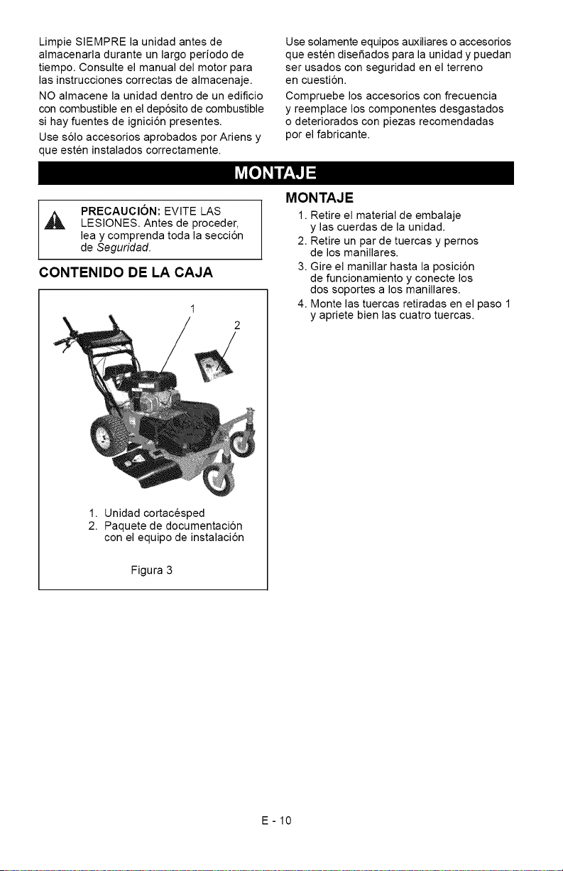
LimpieSIEMPRElaunidadantesde
almacenarladuranteunlargoperiodode
tiempo.Consulteelmanualdelmotorpara
lasinstruccionescorrectasdealmacenaje.
NOalmacenelaunidaddentrodeunedificio
concombustibleeneldep6sitodecombustible
sihayfuentesdeignici6npresentes.
Uses61oaccesoriosaprobadosporAriensy
queesteninstaladoscorrectamente.
Usesolamenteequiposauxiliaresoaccesorios
queestendisefiadosparalaunidadypuedan
serusadosconseguridadenelterreno
encuesti6n.
Compruebelosaccesoriosconfrecuencia
yreemplaceloscomponentesdesgastados
odeterioradosconpiezasrecomendadas
porelfabricante.
PRECAUClON:EVITELAS
_L, LESIONES.Antesdeproceder,
leaycomprendatodalasecci6n
deSeguridad.
CONTENIDO DE LA CAJA
1
2
1. Unidad cortacesped
2. Paquete de documentaci6n
con el equipo de instalaci6n
Figura 3
MONTAJE
1. Retire el material de embalaje
y las cuerdas de la unidad.
2. Retire un par de tuercas y pernos
de los manillares.
3. Gire el manillar hasta la posici6n
de funcionamiento y conecte los
dos soportes a los manillares.
4. Monte las tuercas retiradas en el paso 1
y apriete bien las cuatro tuercas.
E-10
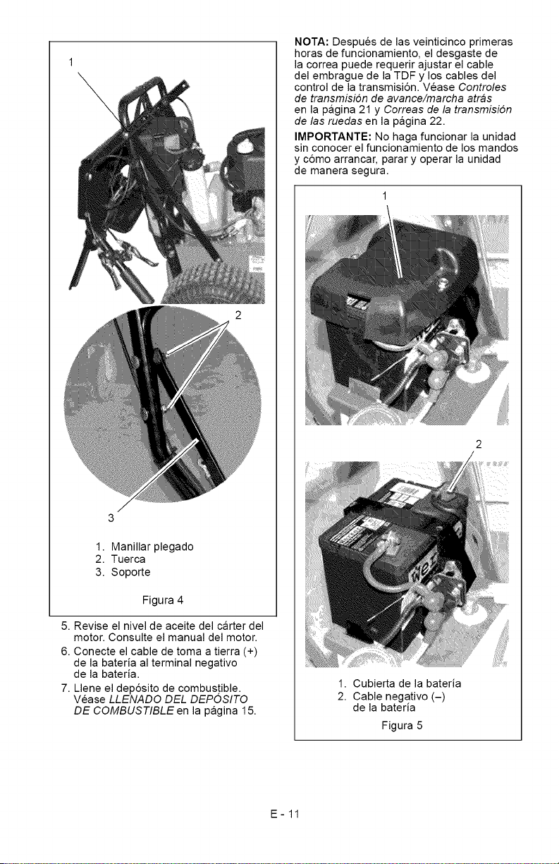
1.Manillarplegado
2.Tuerca
3.Soporte
Figura4
5.Reviseelniveldeaceitedelcarterdel
motor.Consulteelmanualdelmotor.
6.Conecteelcabledetomaatierra(+)
delabateriaalterminalnegativo
delabateria.
7.LleneeldepSsitodecombustible.
VeaseLLENADO DEL DEPOSITO
DE COMBUSTIBLE en la pagina 15.
NOTA: Despues de las veinticinco primeras
horas de funcionamiento, el desgaste de
la correa puede requerir ajustar el cable
del embrague de la TDF y los cables del
control de la transmisiSn. Vease Controles
de transmisi6n de avance/marcha atras
en la pagina 21 y Correas de la transmisi6n
de las ruedas en la pagina 22.
IMPORTANTE: No haga funcionar la unidad
sin conocer el funcionamiento de los mandos
y cSmo arrancar, parar y operar la unidad
de manera segura.
1. Cubierta de la bateria
2. Cable negativo (-)
de la bateria
Figura 5
E-11
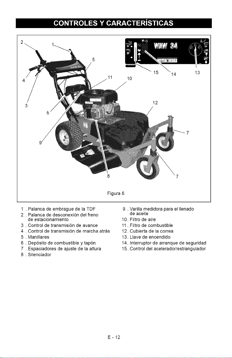
L'd
11
10
12
14
13
Figura 6
1 . Palanca de embrague de la TDF
2 . Palanca de desconexi6n del freno
3
4
5
6
7
8
de estacionamiento
Control de transmisi6n de avance
Control de transmisi6n de marcha atras
Manillares
Dep6sito de combustible y tap6n
Espaciadores de ajuste de la altura
Silenciador
9 . Varilla medidora para el Ilenado
de aceite
10. Filtro de aire
11. Filtro de combustible
12. Cubierta de la correa
13. Llave de encendido
14. Interruptor de arranque de seguridad
15. Control del acelerador/estrangulador
E-12
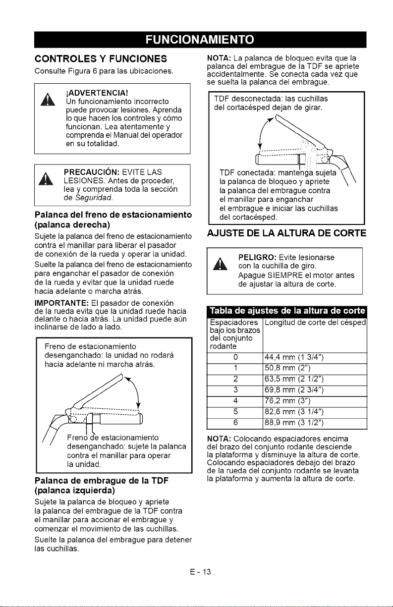
CONTROLES Y FUNCIONES
Consulte Figura 6 para las ubicaciones.
iADVERTENCIA7
Un funcionamiento incorrecto
puede provocar lesiones. Aprenda
Io que hacen los controles y c6mo
funcionan. Lea atentamente y
comprenda el Manual del operador
en su totalidad.
PRECAUCION: EVITE LAS
LESIONES. Antes de proceder,
lea y comprenda toda la secci6n
de Seguridad.
Palanca del freno de estacionamiento
(palanca derecha)
Sujete la palanca del freno de estacionamiento
contra el manillar para liberar el pasador
de conexi6n de la rueda y operar la unidad.
Suelte la palanca del freno de estacionamiento
para enganchar el pasador de conexi6n
de la rueda y evitar que la unidad ruede
hacia adelante o marcha atras.
IMPORTANTE: El pasador de conexi6n
de la rueda evita que la unidad ruede hacia
delante o hacia arras. La unidad puede aQn
inclinarse de lado a lado.
Freno de estacionamiento
desenganchado: la unidad no rodara
hacia adelante ni marcha atras.
estacionamiento
desenganchado: sujete la palanca
contra el manillar para operar
la unidad.
Palanca de embrague de la TDF
(palanca izquierda)
Sujete la palanca de bloqueo y apriete
la palanca del embrague de la TDF contra
el manillar para accionar el embrague y
comenzar el movimiento de las cuchillas.
Suelte la palanca del embrague para detener
las cuchillas.
NOTA: La palanca de bloqueo evita que la
palanca del embrague de la TDF se apriete
accidentalmente. Se conecta cada vez que
se suelta la palanca del embrague.
TDF desconectada: las cuchillas
del cortacesped dejan de girar.
TDF conectada:
la palanca de bloqueo y apriete
la palanca del embrague contra
el manillar para enganchar
el embrague e iniciar las cuchillas
del cortacesped.
AJUSTE DE LA ALTURA DE CORTE
A
PELIGRO: Evite lesionarse
con la cuchilla de giro.
Apague SIEMPRE el motor antes
de ajustar la altura de corte.
i I_ ,'I FtlB[_-=H_i
Espaciadores
bajo los brazos
del conjunto
rodante
0
1
2
3
4
5
6
(;}-1[! _i _1_-] i _ ! | i_-a[! [;][o{o] I (;]
Longitud de corte del cesped
44,4 mm (1 3/4")
50,8 mm (2")
63,5 mm (2 1/2")
69,8 mm (2 3/4")
76,2 mm (3")
82,6 mm (3 1/4")
88,9 mm (3 1/2")
NOTA: Colocando espaciadores encima
del brazo del conjunto rodante desciende
la plataforma y disminuye la altura de corte.
Colocando espaciadores debajo del brazo
de la rueda del conjunto rodante se levanta
la plataforma y aumenta la altura de corte.
E-13
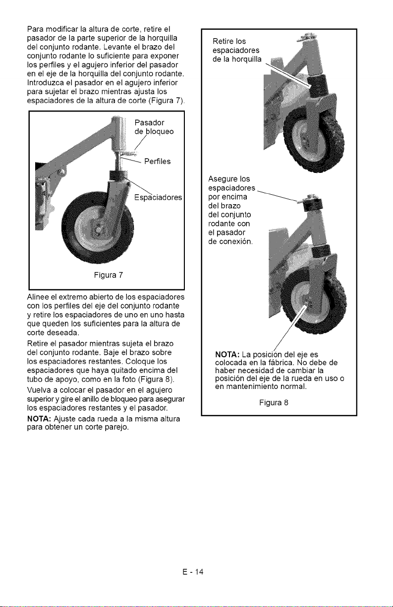
Paramodificarlaalturadecorte,retireel
pasadordelapartesuperiordelahorquilla
delconjuntorodante.Levanteelbrazodel
conjuntorodanteIosuficienteparaexponer
losperfilesyelagujeroinferiordelpasador
enelejedelahorquilladelconjuntorodante.
Introduzcaelpasadorenelagujeroinferior
parasujetarelbrazomientrasajustalos
espaciadoresdelaalturadecorte(Figura7).
Pasador
Figura7
Alineeelextremoabiertodelosespaciadores
conlosperfilesdelejedelconjuntorodante
yretirelosespaciadoresdeunoenunohasta
quequedenlossuficientesparalaalturade
cortedeseada.
Retireelpasadormientrassujetaelbrazo
delconjuntorodante.Bajeelbrazosobre
losespaciadoresrestantes.Coloquelos
espaciadoresquehayaquitadoencimadel
tubodeapoyo,comoenlafoto(Figura8).
Vuelvaacolocarelpasadorenelagujero
superiorygireelanillodebloqueoparaasegurar
losespaciadoresrestantesyelpasador.
NOTA:Ajustecadaruedaalamismaaltura
paraobteneruncorteparejo.
Retirelos
espaciadores
delahorquilla
Asegurelos
espaciadores
porencima
delbrazo
delconjunto
rodantecon
elpasador
deconexi6n.
NOTA:Laposici0ndelejees
colocadaenlafabrica.Nodebede
habernecesidaddecambiarla
posici6ndelejedelaruedaenusoo
enmantenimientonormal.
Figura8
E-14
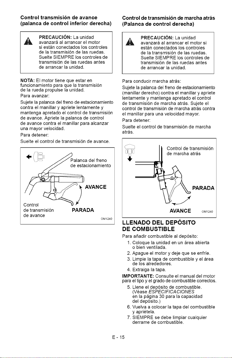
Control transmision de avance Control de transmision de marcha atras
(palanca de control inferior derecha) (Palanca de control derecha)
PRECAUCION: La unidad
avanzara al arrancar el motor
si estan conectados los controles
de la transmisi6n de las ruedas.
Suelte SIEMPRE los controles de
transmisi6n de las ruedas antes
de arrancar la unidad.
A
PRECAUClON: La unidad
avanzara al arrancar el motor si
estan conectados los controles
de la transmisi6n de las ruedas.
Suelte SIEMPRE los controles de
transmisi6n de las ruedas antes
de arrancar la unidad.
NOTA: El motor tiene que estar en
funcionamiento para que la transmisi6n
de la rueda propulse la unidad.
Para avanzar:
Sujete la palanca del freno de estacionamiento
contra el manillar y apriete lentamente y
mantenga apretado el control de transmisi6n
de avance. Apriete la palanca de control
de avance contra el manillar para alcanzar
una mayor velocidad.
Para detener:
Para conducir marcha atras:
Sujete la palanca del freno de estacionamiento
(manillar derecho) contra el manillar y apriete
lentamente y mantenga apretado el control
de transmisi6n de marcha atras. Sujete el
control de transmisi6n de marcha atras contra
el manillar para una velocidad mayor.
Para detener:
Suelte el control de transmisi6n de marcha
atras.
Suelte el control de transmisi6n de avance.
/ ',.... // Palanca del freno _"
/ ....... de estacionamiento
Control /
de transmi PARADA
L de avance ©M1240
Control de transmisi6n
de marcha atras
J
de transmisi6n AVANCE
LLENADO DEL DEPOSITO
DE COMBUSTIBLE
PARADA
OM1240
Para afiadir combustible al dep6sito:
1. Coloque la unidad en un area abierta
o bien ventilada.
2. Apague el motor y deje que se enfrie.
3. Limpie la tapa de combustible y el area
de los alrededores.
4. Extraiga la tapa.
IMPORTANTE: Consulte el manual del motor
para el tipo y el grado de combustible correctos.
5. Llene el dep6sito de combustible.
(Vease ESPECIFICACIONES
en la pagina 30 para la capacidad
del dep6sito.)
6. Vuelva a colocar la tapa del combustible
y aprietela.
7. SIEMPRE se debe limpiar cualquier
derrame de combustible.
E-15
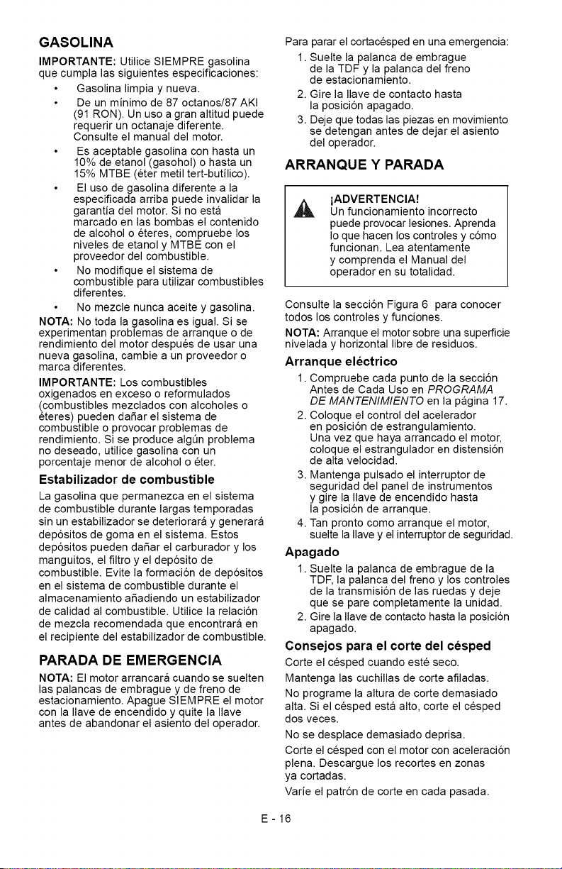
GASOLINA
IMPORTANTE: Utilice SIEMPRE gasolina
que cumpla las siguientes especificaciones:
Gasolina limpia y nueva.
De un minimo de 87 octanos/87 AKI
(91 RON). Un uso a gran altitud puede
requerir un octanaje diferente.
Consulte el manual del motor.
Es aceptable gasolina con hasta un
10% de etanol (gasohol) o hasta un
15% MTBE (eter metil tert-butilico).
El uso de gasolina diferente a la
especMcada arriba puede invalidar la
garantia del motor. Si no esta
marcado en las bombas el contenido
de alcohol o eteres, compruebe los
niveles de etanol y MTBE con el
proveedor del combustible.
No modMque el sistema de
combustible para utilizar combustibles
diferentes.
No mezcle nunca aceite y gasolina.
NOTA: No toda la gasolina es igual. Si se
experimentan problemas de arranque o de
rendimiento del motor despues de usar una
nueva gasolina, cambie a un proveedor o
marca diferentes.
IMPORTANTE: Los combustibles
oxigenados en exceso o reformulados
(combustibles mezclados con alcoholes o
eteres) pueden daSar el sistema de
combustible o provocar problemas de
rendimiento. Si se produce algen problema
no deseado, utilice gasolina con un
porcentaje menor de alcohol o eter.
Estabilizador de combustible
La gasolina que permanezca en el sistema
de combustible durante largas temporadas
sin un estabilizador se deteriorara y generara
dep6sitos de goma en el sistema. Estos
dep6sitos pueden daSar el carburador y los
manguitos, el filtro y el dep6sito de
combustible. Evite la formaci6n de dep6sitos
en el sistema de combustible durante el
almacenamiento aSadiendo un estabilizador
de calidad al combustible. Utilice la relaci6n
de mezcla recomendada que encontrara en
el recipiente del estabilizador de combustible.
PARADA DE EMERGENCIA
NOTA: El motor arrancara cuando se suelten
las palancas de embrague y de freno de
estacionamiento. Apague SIEMPRE el motor
con la Ilave de encendido y quite la Ilave
antes de abandonar el asiento del operador.
Para parar el cortacesped en una emergencia:
1. Suelte la palanca de embrague
de la TDF y la palanca del freno
de estacionamiento.
2. Gire la Ilave de contacto hasta
la posici6n apagado.
3. Deje que todas las piezas en movimiento
se detengan antes de dejar el asiento
del operador.
ARRANQUEYPARADA
iADVERTENCIA7
Un funcionamiento incorrecto
puede provocar lesiones. Aprenda
Io que hacen los controles y c6mo
funcionan. Lea atentamente
y comprenda el Manual del
operador en su totalidad.
Consulte la secci6n Figura 6 para conocer
todos los controles y funciones.
NOTA: Arranque el motor sobre una superficie
nivelada y horizontal libre de residuos.
Arranque electrico
1. Compruebe cada punto de la secci6n
Antes de Cada Uso en PROGRAMA
DE MANTENIMIENTO en la pagina 17.
2. Coloque el control del acelerador
en posici6n de estrangulamiento.
Una vez que haya arrancado el motor,
coloque el estrangulador en distensi6n
de alta velocidad.
3. Mantenga pulsado el interruptor de
seguridad del panel de instrumentos
y gire la Ilave de encendido hasta
la posici6n de arranque.
4. Tan pronto como arranque el motor,
suelte la Ilave y el interruptor de seguridad.
Apagado
1. Suelte la palanca de embrague de la
TDF, la palanca del freno y los controles
de la transmisi6n de las ruedas y deje
que se pare completamente la unidad.
2. Gire la Ilave de contacto hasta la posici6n
apagado.
Consejos para el corte del cesped
Corte el cesped cuando este seco.
Mantenga las cuchillas de corte afiladas.
No programe la altura de corte demasiado
alta. Si el cesped esta alto, corte el cesped
dos veces.
No se desplace demasiado deprisa.
Corte el cesped con el motor con aceleraci6n
plena. Descargue los recortes en zonas
ya cortadas.
Varie el patr6n de corte en cada pasada.
E-16
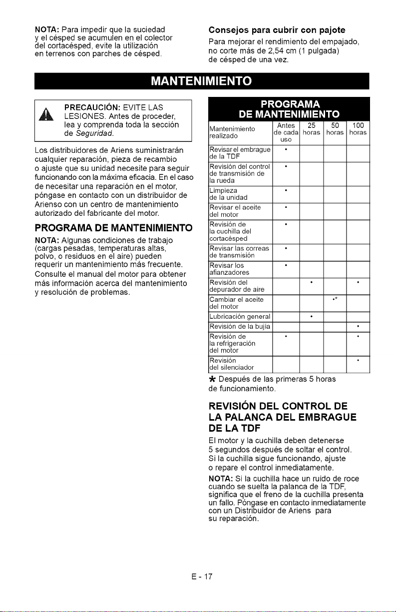
NOTA:Paraimpedirquelasuciedad
yelcespedseacumulenenelcolector
delcortacesped,evitelautilizaci6n
enterrenosconparchesdecesped.
Consejos para cubrir con pajote
Para mejorar el rendimiento del empajado,
no corte mas de 2,54 cm (1 pulgada)
de cesped de una vez.
PRECAUCION: EVITE LAS
LESIONES. Antes de proceder,
lea y comprenda toda la secci6n
de Seguridad.
Los distribuidores de Ariens suministraran
cualquier reparaci6n, pieza de recambio
o ajuste que su unidad necesite para seguir
funcionando con la maxima eficacia. En el caso
de necesitar una reparaci6n en el motor,
p6ngase en contacto con un distribuidor de
Arienso con un centro de mantenimiento
autorizado del fabricante del motor.
PROGRAMA DE MANTENIMIENTO
NOTA: Algunas condiciones de trabajo
(cargas pesadas, temperaturas altas,
polvo, o residuos en el aire) pueden
requerir un mantenimiento mas frecuente.
Consulte el manual del motor para obtener
mas informaci6n acerca del mantenimiento
y resoluci6n de problemas.
Mantenimiento
realizado
Revisar el embrague
de la TDF
Revisi6n del control
de transmisi6n de
la rueda
Limpieza
de la unidad
Revisar el aceite
del motor
Revisi6n de
la cuchilla del
cortacesped
Revisar las correas
de transmisi6n
Revisar los
afianzadores
Revisi6n del
depurador de aire
Cambiar el aceite o*
del motor
Lubricaci6n general
Revisi6n de la bujia
Revisi6n de
la refrigeraci6n
del motor
Revisi6n
del silenciador
Despues de las primeras 5 horas
de funcionamiento.
REVISION DEL CONTROL DE
LA PALANCA DEL EMBRAGUE
DE LA TDF
El motor y la cuchilla deben detenerse
5 segundos despues de soltar el control.
Si la cuchilla sigue funcionando, ajuste
o repare el control inmediatamente.
NOTA: Si la cuchilla hace un ruido de roce
cuando se suelta la palanca de la TDF,
significa que el freno de la cuchilla presenta
un fallo. P6ngase en contacto inmediatamente
con un Distribuidor de Ariens para
su reparaci6n.
E-17
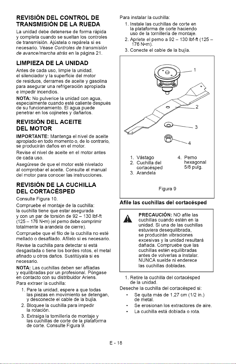
REVISION DEL CONTROL DE
TRANSMISION DE LA RUEDA
La unidad debe detenerse de forma rapida
y completa cuando se sueltan los controles
de transmisi6n. AjQstela o reparela si es
necesario. Vease Controles de transmisi6n
de avance/marcha atras en la pagina 21.
LIMPIEZA DE LA UNIDAD
Antes de cada uso, limpie la unidad,
el silenciador y la superficie del motor
de residuos, derrames de aceite y gasolina
para asegurar una refrigeraci6n apropiada
e impedir incendios.
NOTA: No pulverice la unidad con agua,
especialmente cuando este caliente despues
de su funcionamiento. El agua puede
penetrar en los cojinetes y dafiarlos.
REVISION DEL ACEITE
DEL MOTOR
IMPORTANTE: Mantenga el nivel de aceite
apropiado en todo momento o, de Io contrario,
se produciran dafios en el motor.
Revise el nivel de aceite en el motor antes
de cada uso.
Asegerese de que el motor este nivelado
al comprobar el aceite. Consulte el manual
del motor para conocer las instrucciones.
REVISION DE LA CUCHILLA
DEL CORTACI_SPED
Consulte Figura 10.
Compruebe el montaje de la cuchilla:
la cuchilla tiene que estar asegurada
y con un par de torsi6n de 92 - 130 Ibf-ft
(125 - 176 N°m) (el perno debe comprimir
totalmente la arandela de cierre).
Compruebe que el filo de la cuchilla no este
mellado o desafilado. Afilelo si es necesario.
Revise la cuchilla para detectar siesta
desgastada o tiene los bordes rotos, el metal
afinado u otros dafios. SustitQyala si es
necesario.
NOTA: Las cuchillas deben ser afiladas
y equilibradas pot un profesional. P6ngase
en contacto con su distribuidor Ariens.
Para extraer la cuchilla:
1. Pare la unidad, espere a que todas
las piezas en movimiento se detengan,
y desconecte el cable de la bujia.
2. Bloquee la cuchilla para impedir
la rotaci6n.
3. Extraiga la tomilleria de montaje y
las cuchillas de corte de la plataforma
de corte. Consulte Figura 9.
Para instalar la cuchilla:
1. Instale las cuchillas de corte en
la plataforma de corte haciendo
uso de la tornilleria de montaje.
2. Apriete el pemo a 92 - 130 Ibf-ft (125 -
176 N°m).
3. Conecte el cable de la bujia.
1. Vastago 4. Perno
2. Cuchilla del hexagonal
cortacesped 5/8 pulg.
3. Arandela
Figura 9
Afile las cuchillas del cortacesped
PRECAUCION: NO afile las
cuchillas cuando esten en la
unidad. Si una de las cuchillas
estuviera desequilibrada,
se produciran vibraciones
excesivas y la unidad resultara
dafiada. Compruebe que las
cuchillas esten equilibradas
antes de volverlas a instalar.
NUNCA suelde ni enderece
las cuchillas dobladas.
1. Retire la cuchilla del cortacesped
de la unidad.
Deseche la cuchilla del cortacesped si:
Se quita mas de 1,27 cm (1/2 in.)
de metal.
Se erosionan los extractores de aire.
La cuchilla esta doblada o rota.
E-18
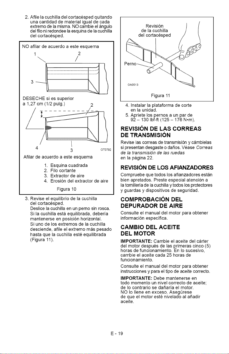
2.Afilelacuchilladelcortacespedquitando
unacantidaddematerialigualdecada
extremodelamisma.NOcambieelangulo
delfiloniredondeelaesquinadelacuchilla
delcortacesped.
NOafilardeacuerdoaesteesquema
1 2
/
3 _[_i_i_i_i_i_i_i_i_i_i_i_i_
DESECHE si es superior
a 1,27 cm (1/2 pulg.) 2
4
3
Afilar de acuerdo a este esquema
OT0792
1. Esquina cuadrada
2. Filo cortante
3. Extractor de aire
4. ErosiSn del extractor de aire
Figura 10
3. Revise el equilibrio de la cuchilla
del cortacesped.
Deslice la cuchilla en un perno sin rosca.
Si la cuchilla esta equilibrada, deberia
mantenerse en posici6n horizontal.
Si uno de los extremos de la cuchilla
desciende, afile el extremo mas pesado
hasta que la cuchilla este equilibrada
(Figura 11).
Revisi6n
de la cuchilla
del cortacesped
Perno_
Figura 11
4. Instalar la plataforma de corte
en la unidad.
5. Apriete los pernos a un par de
92 - 130 Ibf-ft (125 - 176 N°m).
REVISION DE LAS CORREAS
DE TRANSMISION
Revise las correas de transmisi6n y cambielas
si presentan desgaste o dafios. Vease Correas
de la transmisi6n de las ruedas
en la pagina 22.
REVISION DE LOS AFIANZADORES
Compruebe que todos los afianzadores estan
bien apretados. Preste especial atenci6n a
la tornilleria de la cuchilla y todos los protectores
y guardas y dispositivos de seguridad.
COMPROBACION DEL
DEPURADOR DE AIRE
Consulte el manual del motor para obtener
informaci6n especifica.
CAMBIO DEL ACEITE
DEL MOTOR
IMPORTANTE: Cambie el aceite del carter
del motor despues de las primeras cinco (5)
horas de funcionamiento. En Io sucesivo,
cambie el aceite cada 25 horas de
funcionamiento.
Consulte el manual del motor para obtener
instrucciones y para el tipo de aceite correcto.
IMPORTANTE: Debe mantenerse en
todo momento un nivel correcto de aceite;
de Io contrario se dafiaria el motor.
NO Io Ilene en exceso. AsegQrese
de que el motor este nivelado al afiadir
aceite.
E-19
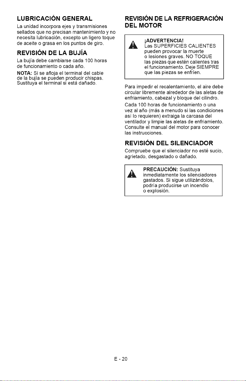
LUBRICACION GENERAL
La unidad incorpora ejes y transmisiones
sellados que no precisan mantenimiento y no
necesita lubricaci6n, excepto un ligero toque
de aceite o grasa en los puntos de giro.
REVISION DE LA BUJiA
La bujia debe cambiarse cada 100 horas
de funcionamiento o cada afio.
NOTA: Si se afloja el terminal del cable
de la bujia se pueden producir chispas.
Sustituya el terminal siesta dafiado.
REVISION DE LA REFRIGERACION
DEL MOTOR
A
iADVERTENCIA7
Las SUPERFICIES CALIENTES
pueden provocar la muerte
o lesiones graves. NO TOQUE
las piezas que esten calientes tras
el funcionamiento. Deje SIEMPRE
que las piezas se enfrien.
Para impedir el recalentamiento, el aire debe
circular libremente alrededor de las aletas de
enfriamiento, cabezal y bloque del cilindro.
Cada 100 horas de funcionamiento o una
vez al afio (mas a menudo si las condiciones
asi Io requieren) extraiga la carcasa del
ventilador y limpie las aletas de enfriamiento.
Consulte el manual del motor para conocer
las instrucciones.
REVISION DEL SILENCIADOR
Compruebe que el silenciador no este sucio,
agrietado, desgastado o dafiado.
PRECAUCION: Sustituya
inmediatamente los silenciadores
gastados. Si sigue utilizandolos,
podria producirse un incendio
o explosi6n.
E - 20
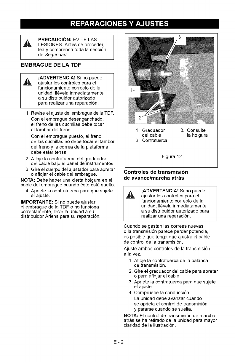
_o,][o]]_l_,,",] W _IZll_',_I_
PRECAUClON: EVITE LAS
,_ LESIONES. Antes de proceder,
lea y comprenda toda la secci6n
de Seguridad.
EMBRAGUE DE LA TDF
iADVERTENCIA7 Si no puede
ajustar los controles para el
funcionamiento correcto de la
unidad, Ilevela inmediatamente
a su distribuidor autorizado
para realizar una reparaci6n.
1. Revise el ajuste del embrague de la TDE
Con el embrague desenganchado,
el freno de las cuchillas debe tocar
el tambor del freno.
Con el embrague puesto, el freno
de las cuchillas no debe tocar el tambor
del freno y la correa de la plataforma
debe estar tensa.
2. Afloje la contratuerca del graduador
del cable bajo el panel de instrumentos.
3. Gire el cuerpo del ajustador para apretar
o aflojar el cable del embrague.
NOTA: Debe haber una cierta holgura en el
cable del embrague cuando este esta suelto.
4. Apriete la contratuerca para que sujete
el ajuste.
IMPORTANTE: Si no puede ajustar
el embrague de la TDF o no funciona
correctamente, Ileve la unidad a su
distribuidor Ariens para su reparaci6n.
1. Graduador
del cable
2. Contratuerca
3. Consulte
la holgura
Figura 12
Controles de transmision
de avance/marcha atras
iADVERTENCIA7 Si no puede
ajustar los controles para el
funcionamiento correcto de la
unidad, Ilevela inmediatamente
a su distribuidor autorizado para
realizar una reparaci6n.
Cuando se gastan las correas nuevas
o la transmisi6n parece perder potencia,
es posible que tenga que ajustar el cable
de control de la transmisi6n.
Ajuste ambos controles de la transmisi6n
a la vez.
1. Afloje la contratuerca de la palanca
de transmisi6n.
2. Gire el graduador del cable para apretar
o para aflojar el cable.
3. Apriete la contratuerca para que sujete
el ajuste.
4. Compruebe la conducci6n.
La unidad debe avanzar cuando
se aprieta el control de transmisi6n
y pararse cuando se suelta.
NOTA: El control de transmisi6n de marcha
atras se ha retirado de la unidad para mayor
claridad de la ilustraci6n.
E-21
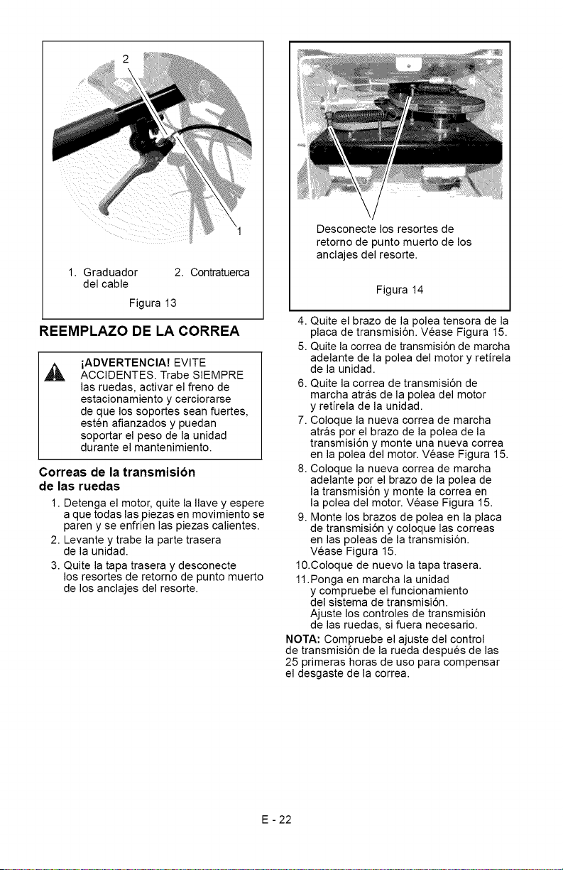
1.Graduador 2. Contratuerca
delcable
Figura13
REEMPLAZO DE LA CORREA
iADVERTENCIA7 EVITE
ACCIDENTES. Trabe SIEMPRE
las ruedas, activar el freno de
estacionamiento y cerciorarse
de que los soportes sean fuertes,
esten afianzados y puedan
soportar el peso de la unidad
durante el mantenimiento.
Correas de la transmision
de las ruedas
1. Detenga el motor, quite la Ilave y espere
a que todas las piezas en movimiento se
paren y se enfrien las piezas calientes.
2. Levante y trabe la parte trasera
de la unidad.
3. Quite la tapa trasera y desconecte
los resortes de retomo de punto muerto
de los anclajes del resorte.
Desconecte los resortes de
retorno de punto muerto de los
anclajes del resorte.
Figura 14
4. Quite el brazo de la polea tensora de la
placa de transmisi6n. Vease Figura 15.
5. Quite la correa de transmisi6n de marcha
adelante de la polea del motor y retirela
de la unidad.
6. Quite la correa de transmisi6n de
marcha atras de la polea del motor
y retirela de la unidad.
7. Coloque la nueva correa de marcha
atras por el brazo de la polea de la
transmisi6n y monte una nueva correa
en la polea del motor. Vease Figura 15.
8. Coloque la nueva correa de marcha
adelante por el brazo de la polea de
la transmisi6n y monte la correa en
la polea del motor. Vease Figura 15.
9. Monte los brazos de polea en la placa
de transmisi6n y coloque las correas
en las poleas de la transmisi6n.
Vease Figura 15.
10.Coloque de nuevo la tapa trasera.
11.Ponga en marcha la unidad
y compruebe el funcionamiento
del sistema de transmisi6n.
Ajuste los controles de transmisi6n
de las ruedas, si fuera necesario.
NOTA: Compruebe el ajuste del control
de transmisi6n de la rueda despues de las
25 primeras horas de uso para compensar
el desgaste de la correa.
E - 22
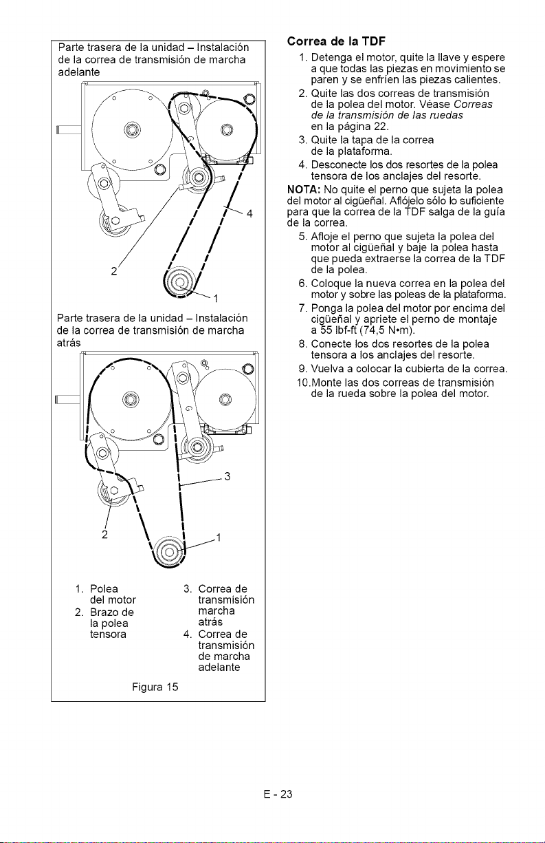
Partetraseradelaunidad- Instalaci6n
delacorreadetransmisiSndemarcha
adelante
@
/
/ I
//
/ I
Parte trasera de la unidad - Instalaci6n
de la correa de transmisiSn de marcha
atras
@
\
j/3
1. Polea
del motor
2. Brazo de
la polea
tensora
3. Correa de
transmisiSn
marcha
atras
4. Correa de
transmisi6n
de marcha
adelante
Figura 15
Correa de la TDF
1. Detenga el motor, quite la Ilave y espere
a que todas las piezas en movimiento se
paren y se enfrien las piezas calientes.
2. Quite las dos correas de transmisi6n
de la polea del motor. Vease Correas
de la transmisi6n de las ruedas
en la pagina 22.
3. Quite la tapa de la correa
de la plataforma.
4. Desconecte los dos resortes de la polea
tensora de los anclajes del resorte.
NOTA: No quite el perno que sujeta la polea
del motor al cig0e_al. Afl6jelo s61oIo suficiente
para que la correa de la TDF salga de la guia
de la correa.
5. Afloje el perno que sujeta la polea del
motor al cigQeSal y baje la polea hasta
que pueda extraerse la correa de la TDF
de la polea.
6. Coloque la nueva correa en la polea del
motor y sobre las poleas de la plataforma.
7. Ponga la polea del motor por encima del
cigQeSal y apriete el perno de montaje
a 55 Ibf-ft (74,5 N°m).
8. Conecte los dos resortes de la polea
tensora a los anclajes del resorte.
9. Vuelva a colocar la cubierta de la correa.
10.Monte las dos correas de transmisi6n
de la rueda sobre la polea del motor.
E - 23
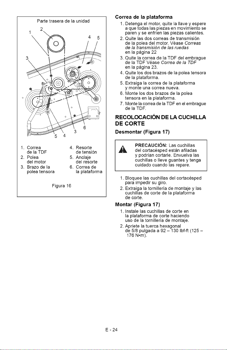
Partetraseradelaunidad
2
4
5 4
6
3
1.Correa 4.Resorte
delaTDF detensi6n
2.Polea 5.Anclaje
delmotor delresorte
3.Brazodela 6.Correade
poleatensora laplataforma
Figura16
Correa de la plataforma
1. Detenga el motor, quite la Ilave y espere
a que todas las piezas en movimiento se
paren y se enfrien las piezas calientes.
2. Quite las dos correas de transmisi6n
de la polea del motor. Vease Correas
de la transmisi6n de las ruedas
en la pagina 22
3. Quite la correa de la TDF del embrague
de la TDF Vease Correa de la TDF
en la pagina 23.
4. Quite los dos brazos de la polea tensora
de la plataforma.
5. Extraiga la correa de la plataforma
y monte una correa nueva.
6. Monte los dos brazos de la polea
tensora en la plataforma.
7. Monte la correa de la TDF en el embrague
de la TDF.
RECOLOCACION DE LA CUCHILLA
DE CORTE
Desmontar (Figura 17)
PRECAUCION: Las cuchillas
del cortacesped estan afiladas
y podrian cortarle. Envuelva las
cuchillas o Ileve guantes y tenga
cuidado cuando las repare.
1. Bloquee las cuchillas del cortacesped
para impedir su giro.
2. Extraiga la tornilleria de montaje y las
cuchillas de corte de la plataforma
de corte.
Montar (Figura 17)
1. Instale las cuchillas de corte en
la plataforma de corte haciendo
uso de la tornilleria de montaje.
2. Apriete la tuerca hexagonal
de 5!8 pulgada a 92 - 130 Ibf-ft (125 -
176 N°m).
E - 24
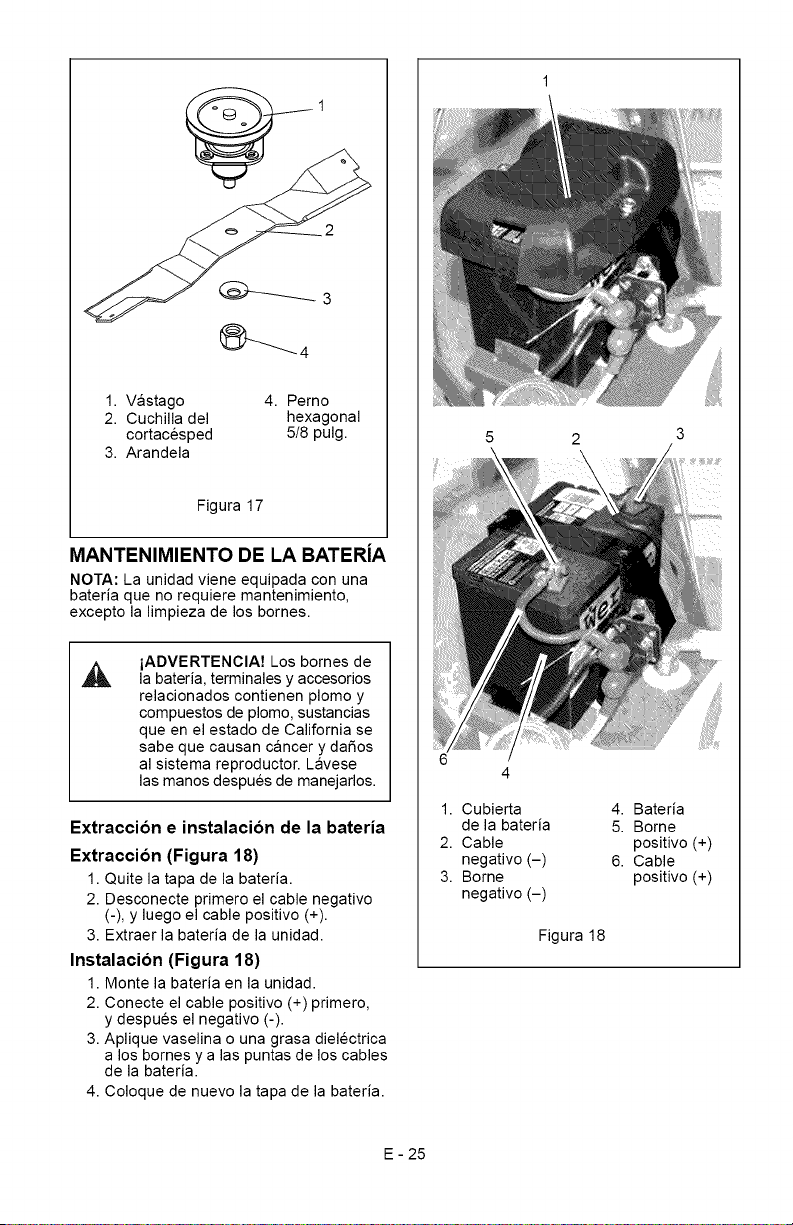
1.Vastago
2.Cuchilladel
cortacesped
3.Arandela
4.Perno
hexagonal
5/8pulg.
Figura17
MANTENIMIENTO DE LA BATERiA
NOTA: La unidad viene equipada con una
bateria que no requiere mantenimiento,
excepto la limpieza de los bornes.
iADVERTENCIA7 Los bomes de
la bateria, terminales y accesorios
relacionados contienen plomo y
compuestos de plomo, sustancias
queen el estado de California se
sabe que causan cancer y daSos
al sistema reproductor. Lavese
las manos despues de manejarlos.
Extraccion e instalacion de la bateria
Extraccion (Figura 18)
1. Quite la tapa de la bateria.
2. Desconecte primero el cable negativo
(-), y luego el cable positivo (+).
3. Extraer la bateria de la unidad.
Instalacion (Figura 18)
1. Monte la bateria en la unidad.
2. Conecte el cable positivo (+) primero,
y despues el negativo (-).
3. Aplique vaselina o una grasa dielectrica
a los bomes y alas puntas de los cables
de la bateria.
4. Coloque de nuevo la tapa de la bateria.
1. Cubierta
de la bateria
2. Cable
negativo (-)
3. Borne
negativo (-)
4. Bateria
5. Borne
positivo (+)
6. Cable
positivo (+)
Figura 18
E - 25
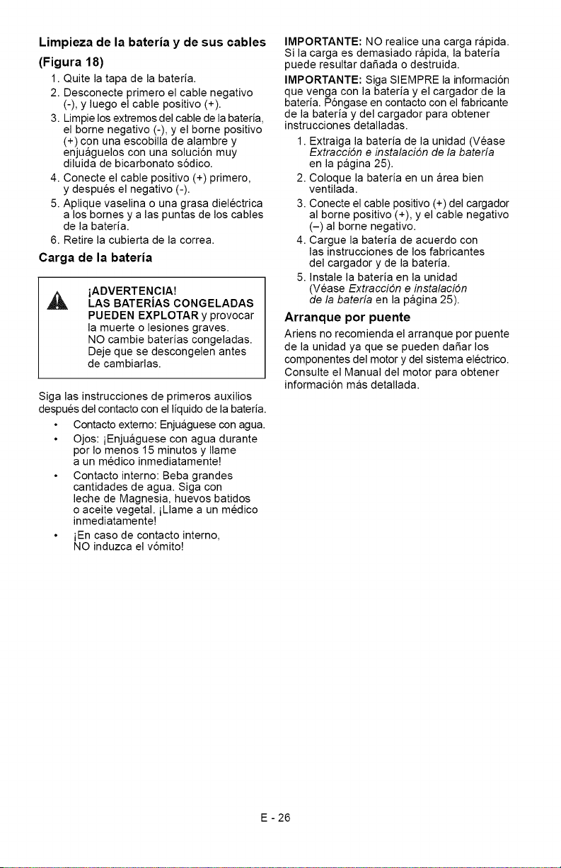
Limpieza de la bateria y de sus cables
(Figura 18)
1. Quite la tapa de la bateria.
2. Desconecte primero el cable negativo
(-), y luego el cable positivo (+).
3. Limpie los extremos del cable de la bateria,
el borne negativo (-), y el borne positivo
(+) con una escobilla de alambre y
enjuaguelos con una soluci6n muy
diluida de bicarbonato s6dico.
4. Conecte el cable positivo (+) primero,
y despues el negativo (-).
5. Aplique vaselina o una grasa dielectrica
a los bomes y alas puntas de los cables
de la bateria.
6. Retire la cubierta de la correa.
Carga de la bateria
iADVERTENCIA7
LAS BATERIAS CONGELADAS
PUEDEN EXPLOTAR y provocar
la muerte o lesiones graves.
NO cambie baterias congeladas.
Deje que se descongelen antes
de cambiarlas.
Siga las instrucciones de primeros auxilios
despues del contacto con el liquido de la bateria.
Contacto externo: Enjuaguese con agua.
Ojos: iEnjuaguese con agua durante
pot Io menos 15 minutos y Ilame
a un medico inmediatamente!
Contacto interno: Beba grandes
cantidades de agua. Siga con
leche de Magnesia, huevos batidos
o aceite vegetal, iLlame a un medico
inmediatamente!
iEn caso de contacto intemo,
NO induzca el v6mito!
IMPORTANTE: NO realice una carga rapida.
Si la carga es demasiado rapida, la bateria
puede resultar dafiada o destruida.
IMPORTANTE: Siga SIEMPRE la informaci6n
que venga con la bateria y el cargador de la
bateria. P6ngase en contacto con el fabricante
de la bateria y del cargador para obtener
instrucciones detalladas.
1. Extraiga la bateria de la unidad (Vease
Extracci6n e instalaci6n de la baterfa
en la pagina 25).
2. Coloque la bateria en un area bien
ventilada.
3. Conecte el cable positivo (+) del cargador
al borne positivo (+), y el cable negativo
(-) al borne negativo.
4. Cargue la bateria de acuerdo con
las instrucciones de los fabricantes
del cargador y de la bateria.
5. Instale la bateria en la unidad
(Vease Extracci6n e instalaci6n
de la baterfa en la pagina 25).
Arranque por puente
Ariens no recomienda el arranque pot puente
de la unidad ya que se pueden dafiar los
componentes del motor y del sistema electrico.
Consulte el Manual del motor para obtener
informaci6n mas detallada.
E - 26
PRECAUClON:EVITELAS
,_ LESIONES. Antes de proceder,
lea y comprenda toda la secci6n
de Seguridad.
IMPORTANTE: No pulverice NUNCA
la unidad con agua a alta presi6n ni la
almacene en el exterior. Almacenela
en un lugar fresco, seco y protegido.
Limpieza
NOTA: Deje que se enfrie la unidad antes
de limpiarla.
Limpie bien la unidad con jab6n suave y agua
a baja presi6n. Elimine con un cepillo la
suciedad y los residuos de todas las superficies.
Retoque todas las superficies rayadas para
evitar que se oxiden. Puede conseguir pintura
para retoques en su distribuidor Ariens.
No utilice abrasivos, disolventes ni
limpiadores agresivos.
Inspeccion
Inspeccione el cortacesped y repare o sustituya
las piezas dafiadas o gastadas para evitar
retrasos cuando se vuelva a usar otra vez.
Compruebe regularmente toda la tornilleria
y mantenga los afianzadores apretados.
Vigile que la unidad este en condiciones
de funcionamiento seguras.
Bolsa de recogida del cesped
Lave la bolsa de recogida del cesped y deje
que se seque antes de guardarla. La bolsa
puede guardarse colocada en el cortacesped.
Motor
AI almacenar la unidad durante periodos
de tiempo prolongados, extraiga todo el
combustible del dep6sito y el carburador
(en seco). Consulte el Manual del motor.
Sistema de combustible
La gasolina que permanezca en el sistema
de combustible durante largas temporadas
sin un estabilizador se deteriorara y generara
dep6sitos de goma en el sistema. Estos
dep6sitos pueden dafiar el carburador y los
manguitos, filtro y dep6sito de combustible.
Evite la formaci6n de dep6sitos en el sistema
de combustible durante el almacenamiento
afiadiendo un estabilizador de calidad al
combustible. Utilice la relaci6n de mezcla
recomendada que encontrara en el recipiente
del estabilizador de combustible.
Para tratar el sistema de combustible antes
del almacenamiento:
1. Afiada estabilizador de combustible
de acuerdo con las instrucciones
del fabricante.
2. Ponga el motor en marcha durante al
menos 10 minutos despues de haber
afiadido estabilizador para permitir
que Ilegue al carburador.
No almacene nunca el motor con combustible
en el dep6sito dentro de un edificio en el que
existan posibles fuentes de ignici6n.
E - 27
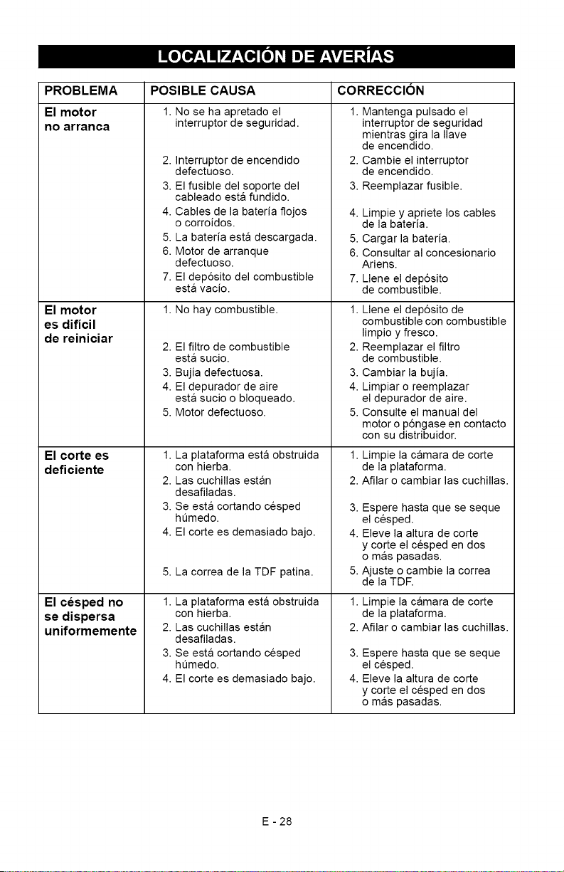
litoX_e_'_llm] = F±\v_;I;_±_,.'_
PROBLEMA
El motor
no arranca
El motor
es dificil
de reiniciar
El corte es
deficiente
El cesped no
se dispersa
uniformemente
POSIBLE CAUSA
1. No se ha apretado el
interruptor de seguridad.
2. Interruptor de encendido
defectuoso.
3. El fusible del soporte del
cableado esta fundido.
4. Cables de la bateria flojos
o corroidos.
5. La bateria esta descargada.
6. Motor de arranque
defectuoso.
7. El dep6sito del combustible
esta vacio.
1. No hay combustible.
2. El filtro de combustible
esta sucio.
3. Bujia defectuosa.
4. El depurador de aire
esta sucio o bloqueado.
5. Motor defectuoso.
1. La plataforma esta obstruida
con hierba.
2. Las cuchillas estan
desafiladas.
3. Se esta cortando cesped
ht]medo.
4. El corte es demasiado bajo.
5. La correa de la TDF patina.
1. La plataforma esta obstruida
con hierba.
2. Las cuchillas estan
desafiladas.
3. Se esta cortando cesped
ht]medo.
4. El corte es demasiado bajo.
CORRECCION
1. Mantenga pulsado el
interruptor de seguridad
mientras gira la Ilave
de encendido.
2. Cambie el interruptor
de encendido.
3. Reemplazar fusible.
4. Limpie y apriete los cables
de la bateria.
5. Cargar la bateria.
6. Consultar al concesionario
Ariens.
7. Llene el dep6sito
de combustible.
1. Llene el dep6sito de
combustible con combustible
limpio y fresco.
2. Reemplazar el filtro
de combustible.
3. Cambiar la bujia.
4. Limpiar o reemplazar
el depurador de aire.
5. Consulte el manual del
motor o p6ngase en contacto
con su distribuidor.
1. Limpie la camara de corte
de la plataforma.
2. Afilar o cambiar las cuchillas.
3. Espere hasta que se seque
el cesped.
4. Eleve la altura de corte
y corte el cesped en dos
o mas pasadas.
5. Ajuste o cambie la correa
de la TDE
1. Limpie la camara de corte
de la plataforma.
2. Afilar o cambiar las cuchillas.
3. Espere hasta que se seque
el cesped.
4. Eleve la altura de corte
y corte el cesped en dos
o mas pasadas.
E - 28
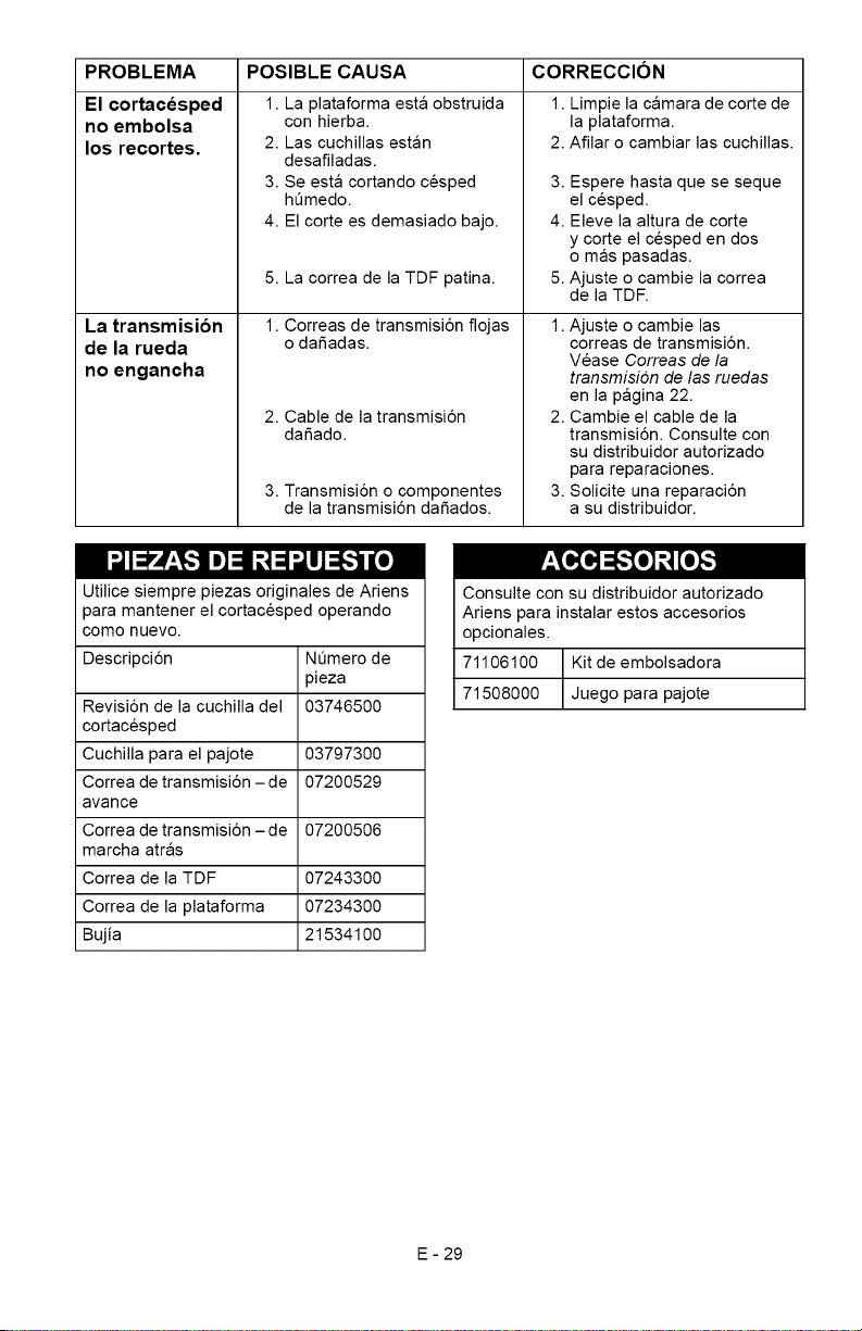
PROBLEMA
El cortacesped
no embolsa
los recortes.
La transmision
de la rueda
no engancha
POSIBLE CAUSA
1. La plataforma esta obstruida
con hierba.
2. Las cuchillas estan
desafiladas.
3. Se esta cortando cesped
hQmedo.
4. El corte es demasiado bajo.
5. La correa de la TDF patina.
1. Correas de transmisi6n flojas
o dafiadas.
2. Cable de la transmisi6n
dafiado.
3. Transmisi6n o componentes
de la transmisi6n dafiados.
CORRECCION
1. Limpie la camara de corte de
la plataforma.
2. Afilar o cambiar las cuchillas.
3. Espere hasta que se seque
el cesped.
4. Eleve la altura de corte
y corte el cesped en dos
o mas pasadas.
5. Ajuste o cambie la correa
de la TDF.
1. Ajuste o cambie las
correas de transmisi6n.
Vease Correas de la
transmisi6n de las ruedas
en la pagina 22.
Cambie el cable de la
transmisi6n. Consulte con
su distribuidor autorizado
para reparaciones.
Solicite una reparaci6n
a su distribuidor.
2.
3.
Utilice siempre piezas originales de Ariens
para mantener el cortacesped operando
como nuevo.
Descripci6n NQmero de
pieza
Revisi6n de la cuchilla del 03746500
cortacesped
Cuchilla para el pajote 03797300
Correa de transmisi6n -de 07200529
avarice
Correa de transmisi6n -de 07200506
marcha atras
Correa de la TDF 07243300
Correa de la plataforma 07234300
Bujia 21534100
Consulte con su distribuidor autorizado
Ariens para instalar estos accesorios
opcionales.
71106100 Kit de embolsadora
71508000 Juego para pajote
E - 29
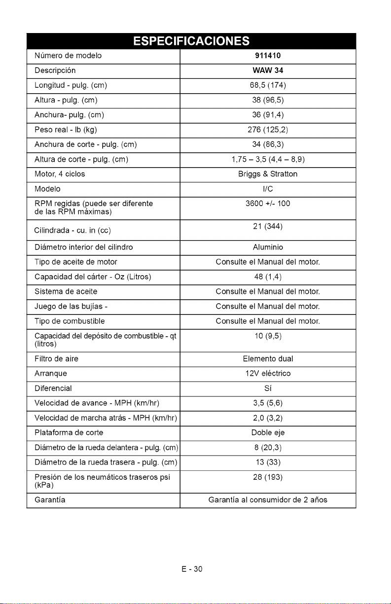
I_,,,,___o,][o_]_,,,,_
NOmero de modelo
Descripci6n
Longitud - pulg. (cm)
Altura - pulg. (cm)
Anchura- pulg. (cm)
Peso real- Ib (kg)
Anchura de corte - pulg. (cm)
Altura de corte - pulg. (cm)
Motor, 4 ciclos
Modelo
RPM regidas (puede ser diferente
de las RPM maximas)
Cilindrada - cu. in (cc)
Diametro interior del cilindro
Tipo de aceite de motor
Capacidad del carter - Oz (Litros)
Sistema de aceite
Juego de las bujias -
Tipo de combustible
Capacidad del dep6sito de combustible - qt
(litros)
Filtro de aire
Arranque
Diferencial
Velocidad de avance - MPH (km/hr)
Velocidad de marcha atras - MPH (km/hr)
Plataforma de corte
Diametro de la rueda delantera - pulg. (cm)
Diametro de la rueda trasera - pulg. (cm)
Presi6n de los neumaticos traseros psi
(kPa)
Garantia
911410
WAW 34
68,5 (174)
38 (96,5)
36 (91,4)
276 (125,2)
34 (86,3)
1,75 - 3,5 (4,4 - 8,9)
Briggs & Stratton
I/C
3600 +!- 100
21 (344)
Aluminio
Consulte el Manual del motor.
48 (1,4)
Consulte el Manual del motor.
Consulte el Manual del motor.
Consulte el Manual del motor.
10 (9,5)
Elemento dual
12V electrico
Si
3,5 (5,6)
2,0 (3,2)
Doble eje
8 (20,3)
13 (33)
28 (193)
Garantia al consumidor de 2 aSos
E - 30
Garantia limitada de dos a os
de la gama Cesped y Jardin
Esta garantia se aplica C/nicamente a cortac_sped de empuje manual de 21 pulgadas,
plataformas de gran anchura, plataformas de gran anchura serie AMP, cultivadoras,
recortadoras de cadena, partidoras de troncos, bordeadoras y escobillas el_ctricas
Ariens Company (Ariens) garantiza al comprador original que los productos comerciales de la marca
Ariens y Gravely fabricados y vendidos pot Ariens se hallaran libres de defectos en materiales y fabricaci6n
pot un periodo de dos afios a partir de la fecha de compra. Un concesionario autorizado Ariens (productos
de la marca Ariens) o Gravely (productos de la marca Gravely) reparara cualquier defecto en los materiales
o en la fabricaci6n, y reparara o sustituira cualquier pieza defectuosa, sujeto alas condiciones, limitaciones
y exclusiones expuestas en la presente garantia. Dicha reparaci6n o sustituci6n se hara sin cargo alguno
(mano de obra y piezas) al comprador original, excepto en los casos indicados mas adelante.
Garantia fimitada de dos a#os sobre bloques de baterias Serie AMP TM y subconjuntos
El bloque de baterias y/o los subconjuntos de cortacesped con operador sentado serie AMP estan
garantizados al comprador original durante un periodo de dos afios a contar desde la fecha de compra.
Ariens sustituira, sin cargo alguno para el comprador original, cualquier bloque de baterias y/o subconjunto
que presente algtJn fallo pot defectos en materiales o fabricaci6n durante un afio a contar desde la fecha
de compra. Durante los 12 meses siguientes, Ariens asumira el coste prorrateado generado pot la
sustituci6n de un bloque de bateria y/o subconjunto que presente algQn fallo por defecto de materiales
o de fabricaci6n. Esta garantia no se aplica a bloques de bateria o subconjuntos que fallen debido
a accidente, negligencia, abuso, mantenimiento inadecuado, almacenamiento inadecuado u operaciones
de carga inadecuadas.
Garantia limitada de un a#o sobre cortac_sped profesionales/comerciales de empuje
manual de 21 pulgadas
Se garantiza al comprador original que los cortacesped de empuje manual de 21 pulgadas etiquetados
o designados pot Ariens como productos profesionales/comerciales para uso profesional, agricola,
comercial o industrial se hallaran libres de defectos de material y de fabricaci6n durante un periodo
de un afio a partir de la fecha de compra.
Garantia fimitada de 90 dias sobre piezas de servicio y accesorios
Se garantiza que las piezas de servicio originales y accesorios de marca Ariens o Gravely estan libres
de defectos en material y mano de obra durante un periodo de 90 dias a contar desde la fecha de compra.
Un distribuidor autorizado Ariens o Gravely reparara o sustituira cualquier pieza o accesorios en estos
casos sin cargo alguno, excepto mano de obra, durante dicho periodo.
Excepto para cortacesped de empuje manual de 21 pulgadas etiquetados o designados pot Ariens como
producto profesional/comercial, la duraci6n de todas las garantias estipuladas se aplica Qnicamente si se
da al producto un uso personal en un hogar o residencia. Si se usa el producto para fines profesionales,
agricolas, comerciales o industriales, la duraci6n de estas garantias sera de 90 dias a partir de la fecha
de compra. Si se arrienda o se alquila un producto, la duraci6n de estas garantias sera de 90 dias a partir
de la fecha de compra.
Excepciones, lirnitaciones, exclusiones
Responsabilidades de los clientes
Registre el producto inmediatamente en el momento de la venta. Si el distribuidor no registra el producto,
el cliente debe rellenar la tarjeta de registro del aparato y devolverla a Ariens Company, o debera registrarse
online en www.ariens.com o www.gravely.com.
Para conseguir un servicio bajo garantia, el comprador original debe:
Llevar a cabo el mantenimiento y ajustes menores segt3n el manual del propietario.
Notificar puntualmente a Ariens o a un representante de servicio autorizado de Ariens o Gravely de la
necesidad de reparaci6n bajo garantia.
Transportar del producto a y desde el lugar de reparaci6n cubierto por la garantia.
Las reparaciones bajo garantia deben ser realizadas pot un representante de servicio Ariens o Gravely.
ARIENS COMPANY
GRAVELY®I STENSC_'I LOCKETS'I NATIONAL®I BYNQRM<_I EVERRIDEC_I GREAT DANEc_' Con L&G 2010
ParaencontrarunrepresentanteautorizadodeserviciotecnicoAriensoGravely,p6ngasecontacto
conAriensen:
655W.RyanStreet
Brillion,WI54110
(920)756-2141
www.ariens.com
www.gravely.com
Excepciones y Limitaciones
Las baterias s61o se garantizan per un periodo de 12 meses a partir de la fecha de compra, en base
a prorrateo. Durante los primeros 90 dias del periodo de garantia, se sustituira una bateria defectuosa
sin cargo alguno. Si el periodo aplicable de garantia supera los 90 dias, Ariens asumira el coste prorrateado
de cualquier bateria defectuosa, hasta Ilegar a los 12 meses a partir de la fecha de la compra. Esta
garantia limitada para baterias no se aplica para bloques de baterias o productos serie AMP.
Exclusiones - Piezas no cubiertas por esta garantia
Los motores y accesorios del motor estan cubiertos s61o per la garantia del fabricante del motor, y no
estan cubiertos pot esta garantia.
Las piezas que no son piezas originales de las marcas Ariens o Gravely no estan cubiertas pot esta
garantia.
Las siguientes piezas de mantenimiento, servicio y recambio no estan cubiertas por esta garantia a
menos que figure en la secci6n Limitaciones anterior: lubricantes, bujias, aceite, filtros de aceite, filtros
de aire, filtros de combustible, guarniciones de frenos, palancas del freno, zapatas, guias, cuchillas
raspadoras, pernos de seguridad, cuchillas del cortacesped, aspas del cortacesped, brazos, escobillas,
faros delanteros, bombillas, cuchillos, cuchillas.
Cualquier defecto que sea resultado del use indebido, alteraci6n, montaje incorrecto, negligencia
o accidente que requiera reparaci6n, no esta cubierto por esta garantia.
Esta garantia s61o aplica a productos adquiridos en Estados Unidos (incluyendo Puerto Rico) y Canada.
En el resto de paises, p6ngase en contacto con el punto de compra para obtener informaci6n sobre
la garantia.
Renuncia
Ariens puede modificar con cierta frecuencia el disefio de sus productos. Nada incluido en esta garantia se
interpretara de ta! modo que obligue a Ariens Company a incorporar tales cambios de disefio en los productos
fabricados previamente, ni se interpretaran tales cambios como una admisi6n de que tales disefios eran
defectuosos.
LIMITA ClON DE REMEDIOS Y DAKIOS
La responsabilidad de Ariens Company bajo esta garantia y bajo cualquier garantia implicita que pueda existir
se limita a la reparaci6n o sustituci6n de cualquier defecto de fabricaci6n, y a la reparaci6n o sustituci6n
de cualquier pieza defectuosa. No podra hacerse responsable a Ariens Company de ningt3n dafio fortuito,
especial o indirecto (incluyendo la perdida de beneficios). AIgunos Estados no permiten la exclusi6n
de dafios fortuitos o indirectos, pot Io que la anterior limitaci6n podria no aplicarse a usted.
RENUNCIA DE GARANTiA ADICIONAL
Ariens Company no proporciona ninguna garantia, expresa o implicita, aparte de la expuesta de
manera expresa en la presente garantia. Si las leyes de su Estado determinan la aplicacibn a Ariens
de una garantia implicita de aptitud o de idoneidad para un prop6sito particular, o de cualquier otro
tipo de garantia implicita, dicha garantia implicita estar_ limitada a la duraci6n de la presente garantia.
Algunos Estados no permiten Iimitaciones a la duracibn de dichas garantias implicitas, por Io que
la anterior limitacibn podria no aplicarse a usted.
Esta garantia le proporciona derechos legales especificos y puede tener tambien otros derechos que varian
de Estado a Estado.
ARIENS COMPANY
GRAVELY®I STENSC_'I LOCKETS'I NATIONAL®I BYNQRM<_I EVERRIDEC_I GREAT DANEc_' Con L&G 2010

Ariens Company
655 West Ryan Street
Brillion, WI 54110-1072
920-756-2141
Fax 920-756-2407
www.ariens.com
A WARNING A
The engine exhaust from this product
contains chemicals known to the State
of California to cause cancer, birth
defects or other reproductive harm.