Loading ...
Loading ...
Loading ...
7
ASSEMBLY
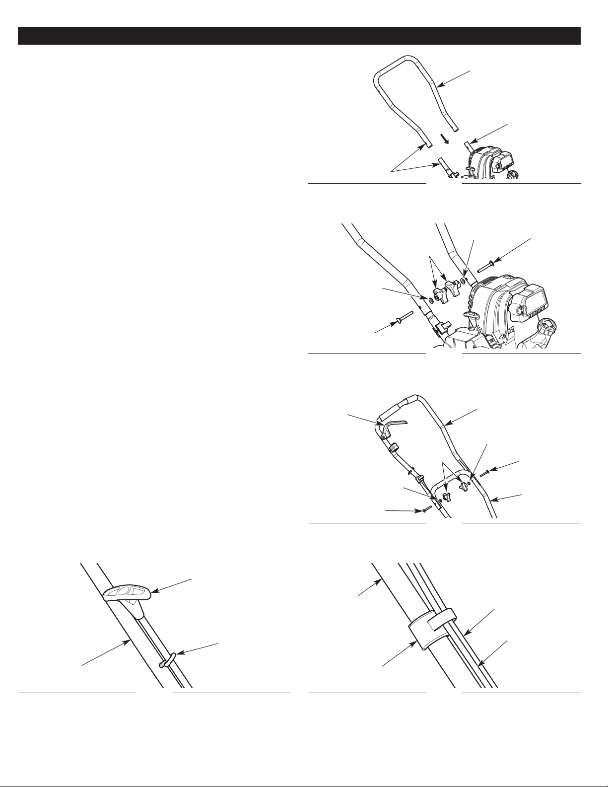
Fig. 2
Washer
Bolt
Knobs
Bolt
Washer
ASSEMBLING THE HANDLE
Installing the Middle Shaft
1. Slide the middle shaft onto the lower shafts (Fig. 1). Keep the
throttle cable and wire assembly to the front of the unit.
2. Align the holes on the middle shaft with the holes on the lower
shafts (Fig. 1).
3. Insert a bolt into each of the aligned holes (Fig. 2).
4. Install a washer onto each bolt (Fig. 2).
5. Install a knob onto each bolt (Fig. 2). Tighten the knobs securely.
Installing the Upper Shaft
1. Position the upper shaft onto the middle shaft. Make sure the
“V” bend in the handle is pointing up (toward the front of the
unit) and that the throttle control is on the right side when the
operater is standing in the operating position (Fig. 10). Keep the
throttle cable and wire assembly to the front of the unit.
2. Align the holes on the upper shaft with the holes on the middle
shaft (Fig. 3).
3. Insert a bolt into each of the aligned holes (Fig. 3).
4. Install a washer onto each bolt (Fig. 3).
5. Install a knob onto each bolt (Fig. 3). Tighten the knobs securely.
Securing the Starter Rope, Throttle Cable and Wire Assembly
1. Pull the starter rope and run it through the eye hook (Fig. 4).
2. Insert the throttle cable and wire assembly into the cable
restraints on the upper and lower shafts (Fig. 5).
NOTE: DO NOT run the throttle cable and wire assembly through
the eye hook.
NOTE: DO NOT bend or pinch the throttle cable or wire assembly.
Fig. 1
Holes
Lower Shaft
Middle Shaft
Fig. 3
Washer
Bolt
Knobs
Bolt
Washer
Upper Shaft
Middle Shaft
Throttle
Control
Fig. 4
Starter Rope
Upper Shaft
Eye Hook
Fig. 5
Cable Restraint
Wire Assembly
Shaft
Throttle Cable
Loading ...
Loading ...
Loading ...