Viking Use/Installation Guide
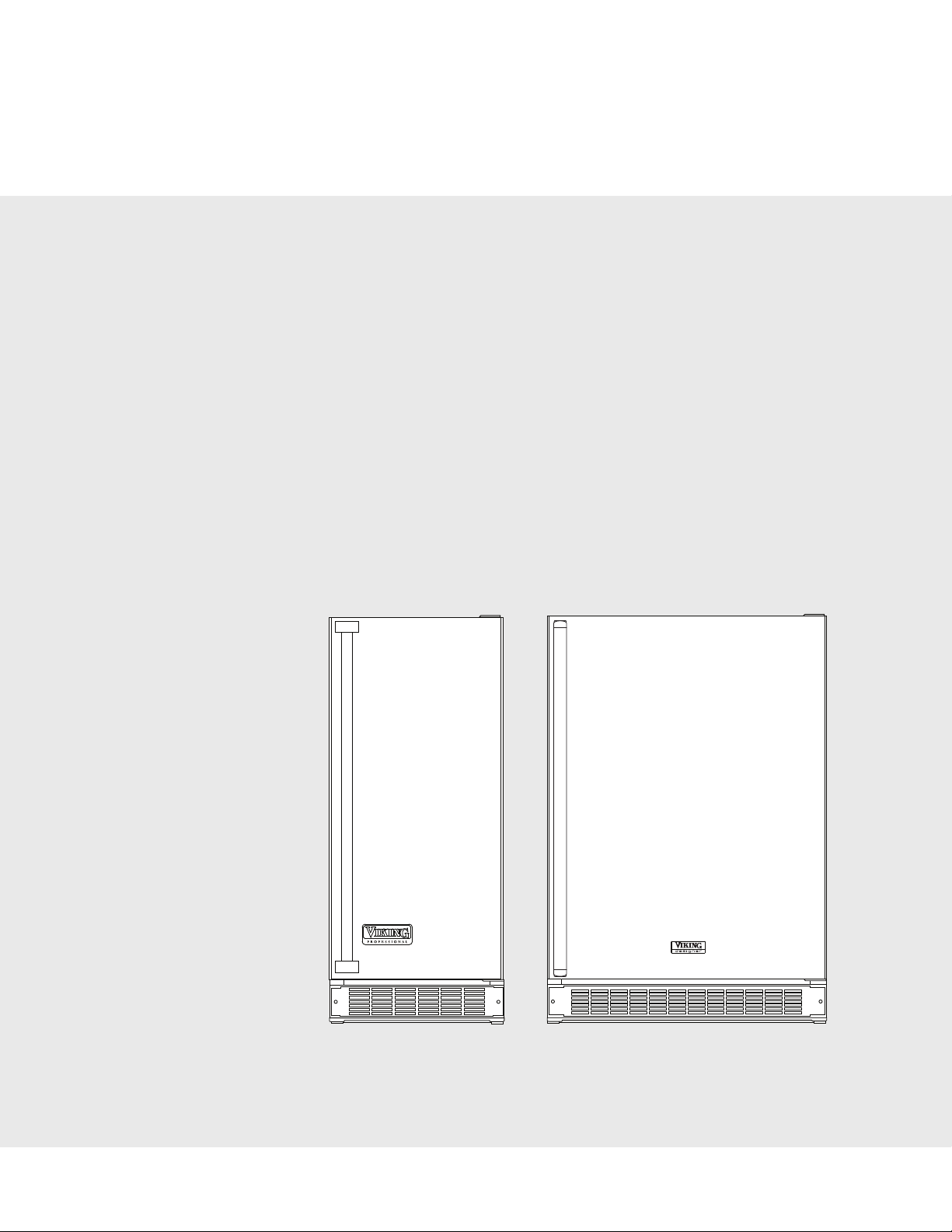
Undercounter/Freestanding Wine Cellars
2
IMPORTANT - PLEASE READ AND FOLLOW
••
Before beginning, please read these instructions completely and carefully.
• Do not remove permanently affixed labels, warnings, or plates from the product. This may void the warranty.
• Please observe all local and national codes and ordinances.
• Please ensure that this product is properly grounded.
• The installer should leave these instructions with the consumer who should retain for local inspector’s use and for future reference.
It is your responsibility to be sure your wine cellar is:
• located so the front is not blocked to restrict incoming or discharge air flow.
• properly leveled.
• located in a well ventilated area.
• connected to the proper kind of outlet, with the correct electric supply and grounding. A 115V, 60 Hz, 15 amp fused electrical
supply is required. NOTE: Time delay fuse or circuit breaker is recommended.
• not used by anyone unable to operate it properly.
• used only for its intended purpose.
• properly maintained.
•SAVE THESE INSTRUCTIONS•
PROPER DISPOSAL (OF OLD REFRIGERATION UNIT)
WARNING
To reduce the risk of fire, electric shock, or injury when using your unit, follow these basic precautions:
• Read all instructions before using the unit.
• Never allow children to operate, play with, or crawl inside the unit.
• Never clean unit parts with flammable fluids. The fumes can create a fire hazard or explosion.
• Always turn the power on/off switch (located behind the air grille on top right side) to the OFF position before attempting to change
light bulbs, clean, or service the unit.
FOR YOUR SAFETY
DO NOT STORE OR USE GASOLINE OR OTHER FLAMMABLE VAPORS AND LIQUIDS IN THE VICINITY OF THIS OR ANY OTHER
APPLIANCE. THE FUMES CAN CREATE A FIRE HAZARD OR EXPLOSION.
DANGER
RISK OF CHILD ENTRAPMENT
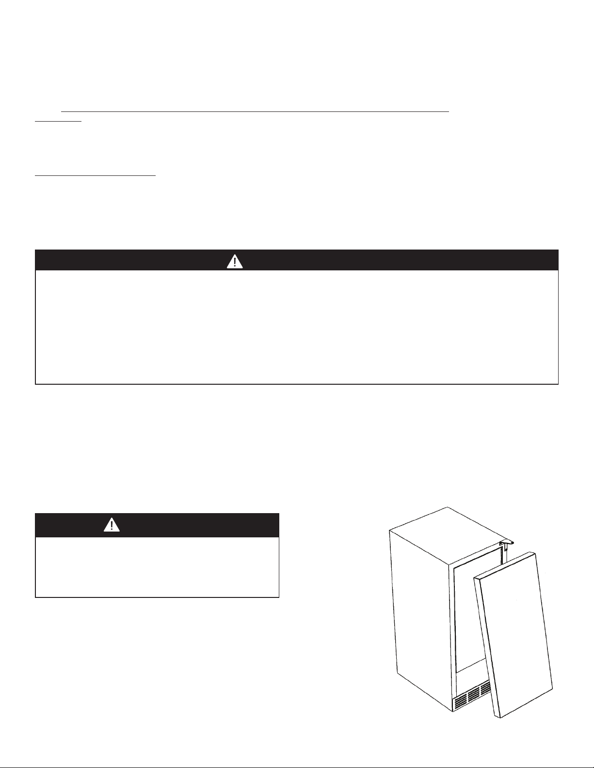
Before You Throw Away Your Old Refrigeration Unit:
• Take off the doors.
• Leave the shelves in place so that children may not easily
climb inside.
IMPORTANT: Child entrapment and suffocation are not problems of the past.
Junked or abandoned refrigeration units are still dangerous... even if they will sit for
“just a few days.”
IMPORTANT:
Now that you have a new wine cellar, it is extremely important that you dispose of your
old appliance in a way that minimizes the possibility that children will find it. There
have been many cases in years past of children crawling inside junked and abandoned
refrigeration units and becoming trapped or suffocated.
Contact your municipal waste disposal authority to find out the best and safest way to
dispose of your old refrigeration unit.
A GFI shall be used if required by NFPA-70 (National Electric Code), federal/state/local laws, or local
ordinances.
• The required use of a GFI is normally related to the location of a receptacle with respect to any
significant sources of water or moisture.
• Viking Range Corporation will NOT warranty any problems resulting from GFI outlets which are not
installed properly or do not meet the requirements below.
If the use of a GFI is required
, it should be:
• Of the receptacle type (breaker type or portable type NOT recommended)
• Used with permanent wiring only (temporary or portable wiring NOT recommended)
• On a dedicated circuit (no other receptacles, switches or loads in the circuit)
• Connected to a standard breaker of appropriate size (GFI breaker of the same size NOT recommended)
• Rated for Class A (5 mA +/- 1 mA trip current) as per UL 943 standard)
• In good condition and free from any loose-fitting gaskets (if applicable in outdoor situations)
• Protected from moisture (water, steam, high humidity) as much as reasonably possible
3
GENERAL INFORMATION
Unpack
1. Remove banding from bottom of carton. Lift carton up and off of the wine cellar
2. Remove all tape and packaging material from the outside and inside of the cabinet.
3. Keep all carton packaging until your wine cellar has been thoroughly inspected and found to be in good condition.
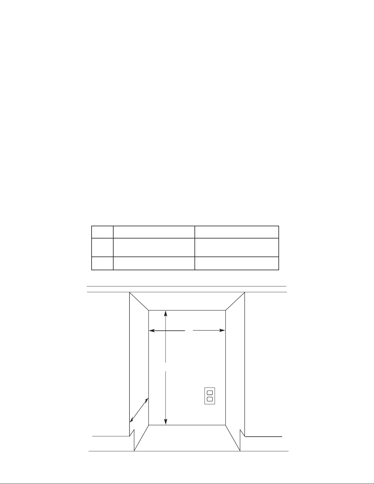
AREA REQUIREMENTS
1. Place unit so the front side will be completely unobstructed to provide proper air flow. The unit may be closed in
on the top and three sides, but the front MUST BE unobstructed for air circulation and proper operation.
Installation should be such that the cabinet can be moved for servicing if necessary.
2. Unit should be in a well ventilated area with temperature above 55°F (13°C) and below 110°F (43°C). Best results
are obtained at temperatures between 65°F (18°C) and 80°F (27°C) for built-in models and 65°F (18°C) and 90°F
(32°C) for freestanding models.
3. Provisions for electricity should be determined before placing unit in proper place.
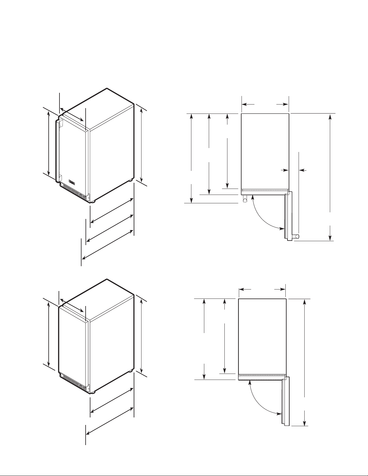
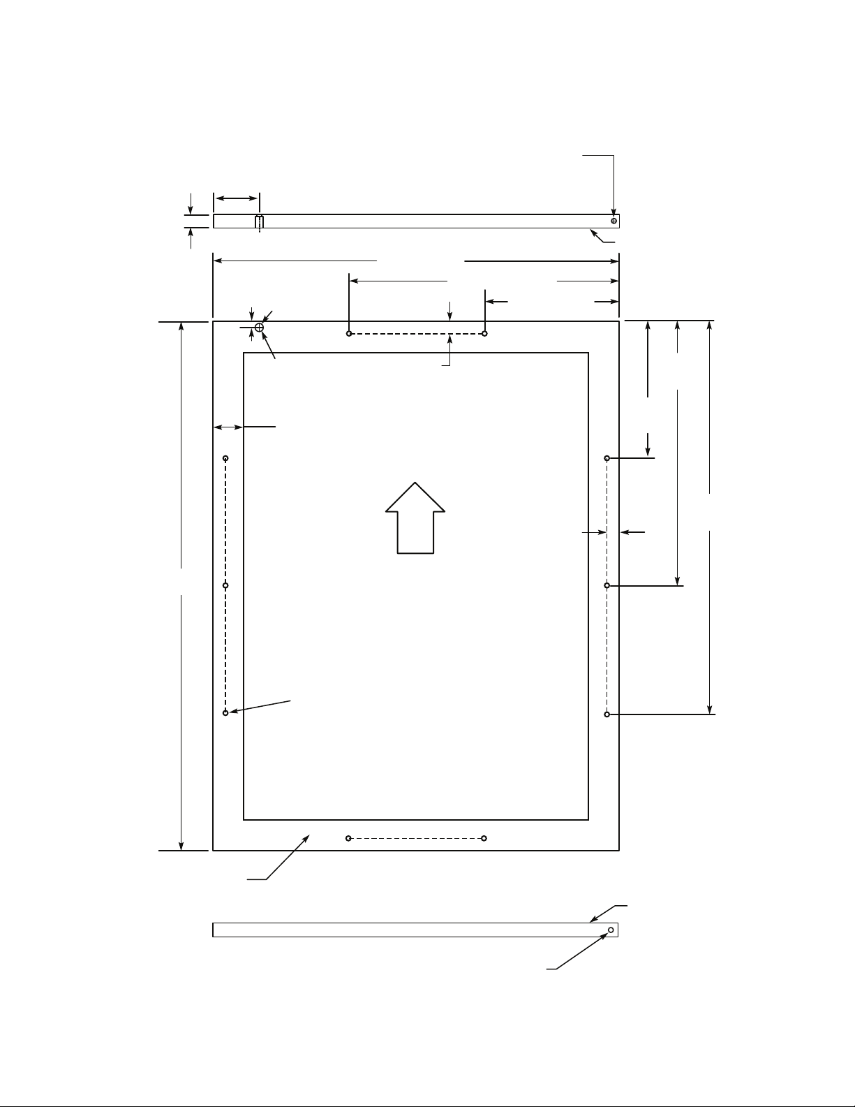
24” W. Models
15” W. Models
*Add 1/4” (.64 cm) to cutout width if door is recessed between cabinets.
A 15” (38.1 cm)* 24” (61.0 cm)*
B
Min. 34-1/2” (87.6 cm)
Max. 35-1/8” (89.2 cm)
Min. 34-1/2” (87.6 cm)
Max. 35-1/8” (89.2 cm)
C 24” (61.0 cm) 24” (61.0 cm)
Units Certified for Outdoor Use - outdoor models contain a T after the base model number (ex. VUWC144T) and
have a stainless steel outer cabinet.
1. Place unit so the front side will be completely unobstructed to provide proper air flow. The unit may be closed in
on the top and three sides, but the front MUST BE unobstructed for air circulation and proper operation.
Installation should be such that the cabinet can be moved for servicing if necessary.
2. Unit should be in a well ventilated area with temperature above 40°F (4.4°C) and below 110°F (43°C). Best results
are obtained at temperatures between 60°F (16°C) and 100°F (38°C).
3. Provisions for electricity should be determined before placing unit in proper place.
A
B
C
UNDERCOUNTER CABINET CUTOUT
4
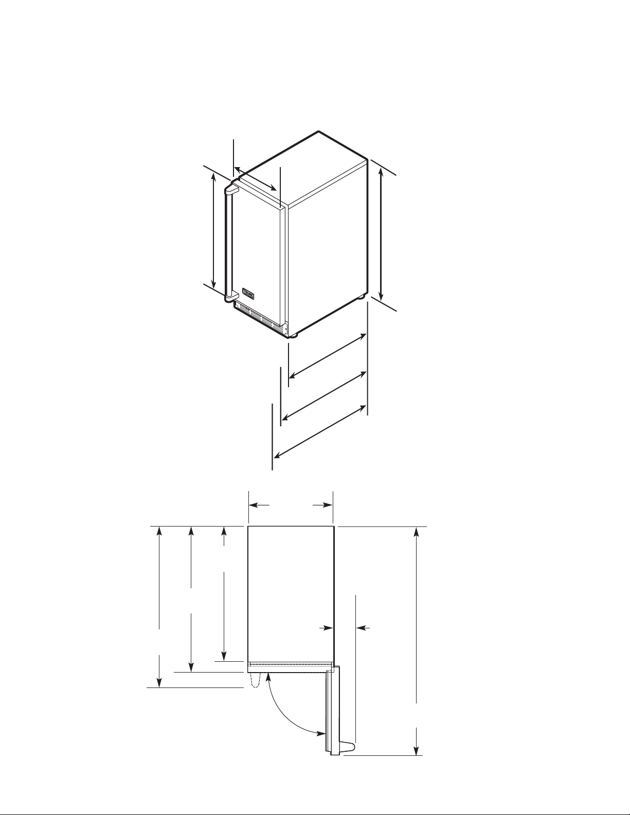
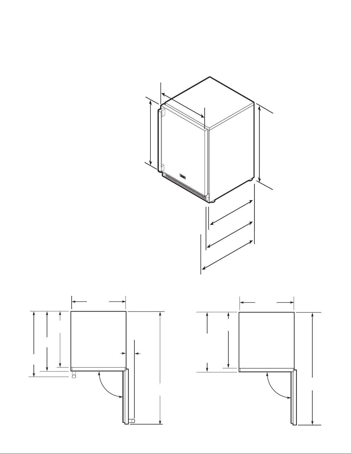
SPECIFICATIONS/DIMENSIONS
PROFESSIONAL - 15”W. Models
B
asic Electric Data
•115 VAC/60 Hz
•Maximum amps - 3.0
Approximate Shipping Weight - 110 lbs. (49.5 kg)
14-3/4”
(37.5 cm)
90.0°
37-3/16”
(94.5 cm)
2-1/2”
(6.4 cm)
21-3/16”
(53.8 cm)
26-1/8”
(66.4 cm)
23-5/8”
(60.0 cm)
Dimensions
VUWC 15”W.
Door Swing
VUWC 15”W.
2
1
-
3
/
1
6
”
(
5
3
.
8
c
m
)
2
3
-
5
/
8
”
(
6
0
.
0
c
m
)
2
6
-
1
/
8
”
(
6
6
.
4
c
m
)
3
4
-
1
/
4
”
(
8
7
.
0
c
m
)
m
i
n
.
t
o
3
5
”
(
8
8
.
9
c
m
)
m
ax
.
(
w
i
t
h
l
e
v
e
l
i
n
g
l
e
g
s
f
u
l
l
y
e
x
t
e
n
d
e
d
)
1
4
-
3
/
4
”
(
3
7
.
5
c
m
)
14-3/4”
(37.5 cm)
1
4
-
3
/
4
”
(
3
7
.
5
c
m
)
30-
3/
4”
(
7
8
.
1
c
m
)
5
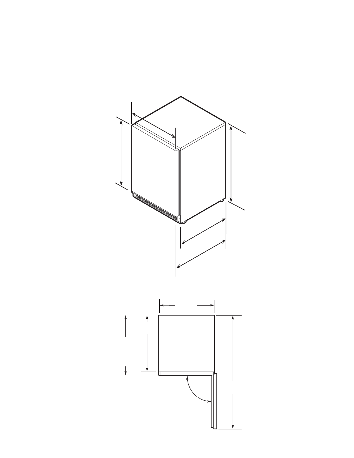
SPECIFICATIONS/DIMENSIONS
DESIGNER - 15”W. Models
B
asic Electric Data
•115 VAC/60 Hz
•Maximum amps - 3.0
Approximate Shipping Weight - 110 lbs. (49.5 kg)
2
3
-
5
/
8
”
(
6
0
.
0
c
m
)
2
1
-
3
/
1
6
”
(
5
3
.
8
c
m
)
3
0
-
3
/
4”
(
7
8
.
1
c
m
)
1
4
-
3
/
4
”
(
3
7
.
5
c
m
)
14-3/4”
(37.5 cm)
1
4
-
3
/
4
”
(
3
7
.
5
c
m
)
3
4
-
1
/
4
”
(
8
7
.
0
c
m
)
m
i
n
.
t
o
3
5
”
(
8
8
.
9
c
m
)
m
a
x
.
(
wi
t
h
l
e
v
e
l
i
n
g
l
e
g
s
f
u
l
l
y
e
x
t
e
n
d
e
d
)
2
6
-
1
/
8
”
(
6
6
.
4
c
m
)
14-3/4”
(37.5 cm)
37-3/16”
(94.5cm)
2-1/2”
(6.4 cm)
21-3/16”
(53.8 cm)
26-1/8”
(66.4 cm)
23-5/8”
(60.0 cm)
90.0°
Door Swing
DUWC 15”W.
Dimensions
DUWC 15”W.
90.0°
14-3/4”
(37.5 cm)
37-3/16”
(94.5cm)
21-3/16”
(53.8 cm)
23-7/16”
(59.5 cm)
to front of
locally supplied
custom panel
Door Swing
DFUW 15”W.
2
1
-
3
/
1
6
”
(
5
3
.
8
c
m
)
2
3
-
7
/
1
6
”
(
5
9
.
5
c
m
)
(
t
o
f
r
o
n
t
o
f
l
o
c
a
l
l
y
s
u
p
p
l
i
e
d
c
u
s
t
o
m
p
a
n
e
l
)
30-
3
/
4
”
(
7
8
.
1
c
m
)
1
4
-
3
/
4
”
(
3
7
.
5
c
m
)
14-3/4”
(37.5 cm)
1
4
-
3
/
4
”
(
3
7
.
5
c
m
)
3
4
-
1
/
4
”
(
8
7
.
0
c
m
)
m
i
n
.
t
o
3
5
”
(
8
8
.
9
c
m
)
m
a
x
.
(
w
i
t
h
l
e
v
e
l
i
n
g
l
e
g
s
f
u
l
l
y
e
x
t
e
n
d
e
d
)
Dimensions
DFUW 15”W.
6
23-7/8”
(60.6 cm)
90.0°
2-1/2”
(6.4 cm)
47-1/4”
(120.0 cm)
22”
(55.9 cm)
26-7/8”
(68.3 cm)
24-3/8”
(61.9 cm)
3
0
-
3
/
4
”
(
7
8
.
1
c
m
)
2
2
”
(
5
5
.
9
c
m
)
2
4
-
3
/
8
”
(
6
1
.
9
c
m
)
2
3
-
7
/
8
”
(
6
0
.
6
c
m
)
23-7/8”
(60.6 cm)
2
3
-
7
/
8
”
(
6
0
.
6
c
m
)
2
6
-
7
/
8
”
(
6
8
.
3
c
m
)
3
4
-
1
/4
”
(
8
7
.
0
c
m
)
m
i
n
.
t
o
3
5
”
(
8
8
.
9
c
m
)
m
a
x
.
(
w
i
t
h
l
e
v
e
l
i
n
g
l
e
g
s
f
u
l
l
y
e
x
t
e
n
d
e
d
)
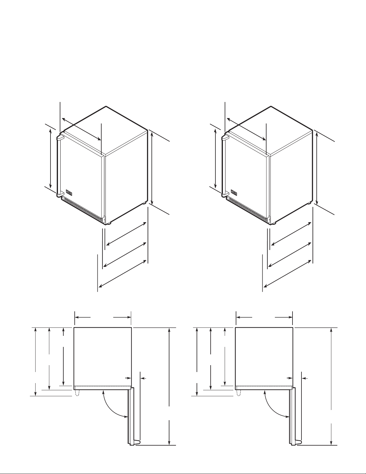
Dimensions VUWC 24”W. - Single Zone
SPECIFICATIONS/DIMENSIONS
PROFESSIONAL - 24” W. Models
B
asic Electric Data
• 115 VAC/60 Hz
• Maximum amps - 3.3
• Approximate Shipping Weight
Single Zone - 140 lbs. (63.2 kg)
Dual Zone - 170 lbs. (76.5 kg)
23-7/8”
(60.6 cm)
90.0°
2-1/2”
(6.4 cm)
46-1/2”
(118.1 cm)
21-1/2”
(54.6 cm)
26-3/8”
(67.0 cm)
23-7/8”
(60.7 cm)
Door Swing VUWC 24”W. - Single Zone
Door Swing VUWC 24”W. - Dual Zone
3
0
-
3
/
4
”
(
7
8
.
1
c
m
)
2
1
-
1
/
2
”
(
5
4
.
6
c
m
)
2
3
-
7
/
8
”
(
6
0
.
7
c
m
)
2
3
-
7
/
8
”
(
6
0
.
6
c
m
)
23-7/8”
(60.6 cm)
2
3
-
7
/
8
”
(
6
0
.
6
c
m
)
2
6
-
3
/
8
”
(
6
7
.
0
c
m
)
3
4
”
(
8
6
.
4
c
m
)
m
i
n
.
t
o
3
4
-
3
/
4
”
(
8
8
.
3
c
m
)
m
a
x
.
(
w
i
t
h
l
e
v
e
l
i
n
g
l
e
g
s
f
u
l
l
y
e
x
t
e
n
d
e
d
)
Dimensions VUWC 24”W. - Dual Zone
7
23-7/8”
(60.6 cm)
90.0°
47-1/4”
(120.0 cm)
2-1/2”
(6.4 cm)
26-7/8”
(68.3 cm)
24-3/8”
(61.9 cm)
22”
(55.9 cm)
3
0
-
3
/
4
”
(
7
8
.
1
cm
)
2
2
”
(
5
5
.
9
c
m
)
2
4
-
3
/
8
”
(
6
1
.
9
c
m
)
2
3
-
7
/
8
”
(
6
0
.
6
cm
)
23-7/8”
(60.6 cm)
2
3
-
7
/
8
”
(
6
0
.
6
cm
)
2
6
-
7
/
8
”
(
6
8
.
3
c
m
)
3
4
-
1
/
4
”
(
8
7
.
0
c
m
)
m
i
n
.
t
o
3
5
”
(
8
8
.
9
c
m
)
m
a
x
.
(
w
i
t
h
l
e
v
e
l
i
n
g
l
e
g
s
f
u
l
l
y
e
x
t
e
n
d
e
d
)
SPECIFICATIONS/DIMENSIONS
DESIGNER - 24” W. Models
B
asic Electric Data
• 115 VAC/60 Hz
• Maximum amps - 3.3
• Approximate Shipping Weight
Single Zone - 140 lbs. (63.2 kg)
Dual Zone - 170 lbs. (76.5 kg)
Dimensions DUWC 24”W. - Single Zone
Door Swing DUWC 24”W. - Single Zone
Door Swing DFUW 24”W. - Single Zone
23-7/8”
(60.6 cm)
90.0°
47-1/4”
(120.0 cm)
22”
(55.9 cm)
24-3/16”
(61.4 cm)
to front of
locally supplied
custom panel
3
0
-
3
/
4
”
(
7
8
.
1
cm
)
2
1
-
1
/
2
”
(
5
4
.
6
c
m
)
2
3
-
7
/
8
”
(
6
0
.
7
c
m
)
2
3
-
7
/
8
”
(
6
0
.
6
cm
)
23-7/8”
(60.6 cm)
2
3
-
7
/
8
”
(
6
0
.
6
cm
)
3
4
”
(
8
6
.
4
c
m
)
m
i
n
.
t
o
3
4
-
3
/
4
”
(
8
8
.
3
c
m
)
m
a
x
.
(
w
i
t
h
l
e
v
e
l
i
n
g
l
e
g
s
f
u
l
l
y
e
x
t
e
n
d
e
d
)
SPECIFICATIONS/DIMENSIONS
DESIGNER - 24” W. Models
Basic Electric Data
•
115 VAC/60 Hz
•
Maximum amps - 3.3
•
Approximate Shipping Weight
S
ingle Zone - 140 lbs. (63.2 kg)
Dual Zone - 170 lbs. (76.5 kg)
Dimensions DFUW 24”W. - Dual Zone
Door Swing DFUW 24”W. - Dual Zone
23-7/8”
(60.6 cm)
90.0°
46-1/2”
(118.1 cm)
21-1/2”
(54.6 cm)
23-11/16”
(60.2 cm)
to front of
locally supplied
custom panel
8
9
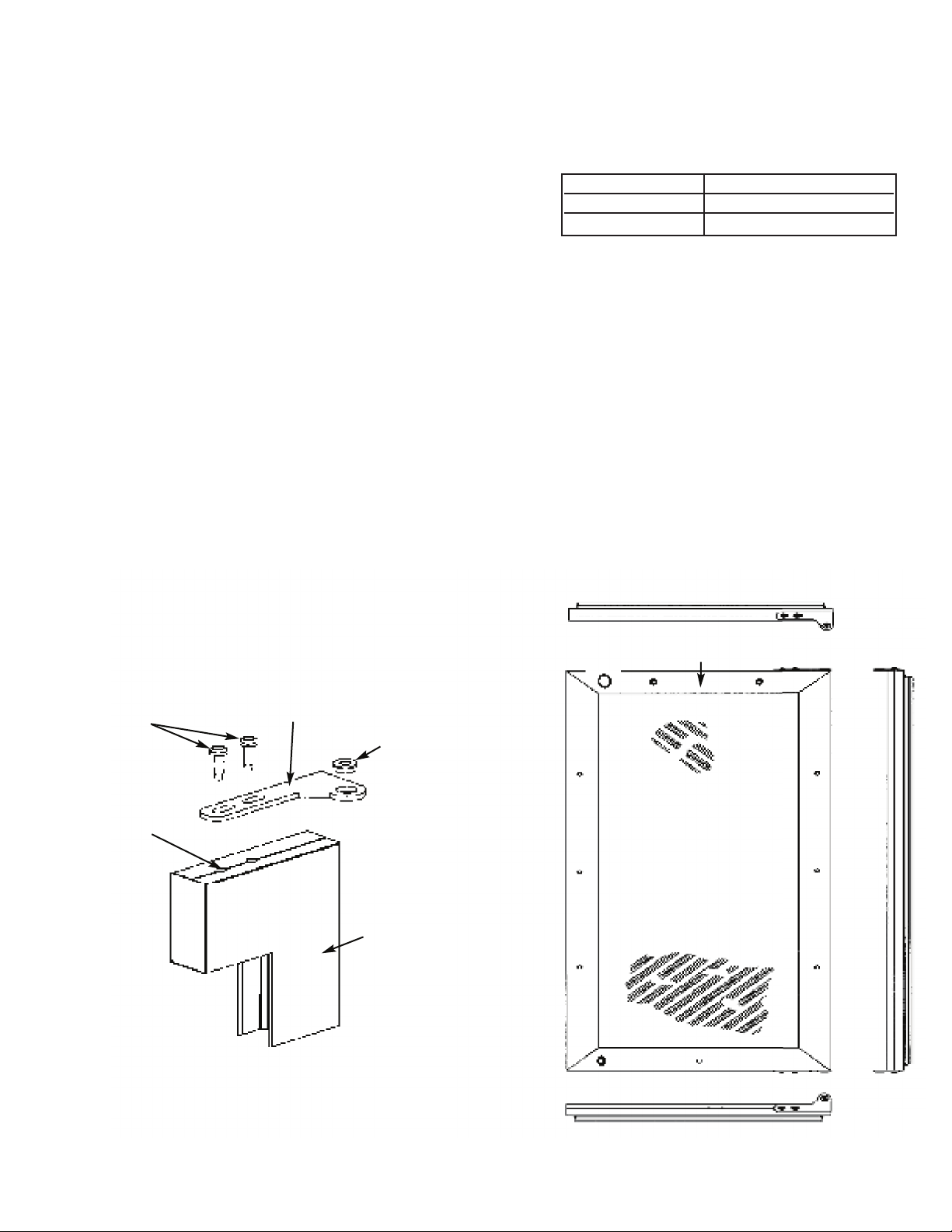
FIGURE 1 FIGURE 2
Typical Top and Bottom Door
Hinge Bracket Assembly
Door Front
Surface
Shoulder Bushing
Door
Hinge
Bracket
#10-32
Machine
Screw
Door Hinge
Screw Holes
This surface parallel to the unit.
(Right hinge door shown.)
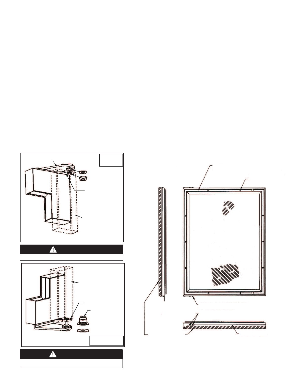
CUSTOM WOOD FRAME INSTALLATION (DFUW Model)
NOTE: Weight of wood panel must not exceed 20 lbs.
W
ood Screws
1
. A #10 pan head wood screw should be used to properly secure the wood panel. A total of 8 screws will be needed.
2. Only use pan head screws.
3. DO NOT select a screw that is longer than the wood thickness at
the screw locations.
4. Use recommended pilot holes for the frame material. (See chart)
Working Material Wood Screw Size #10
Hardwood 3/32 (0.24 cm)
S
oftwood 5/64 (0.20 cm)
Assembling Door Hinge Brackets
(Disregard if hinge brackets are already attached)
1. Attach the top and bottom door hinge brackets to the door with the #10-32 machine screws and a 1/8” allen head
driver as shown in Figure 1 below.
2. Press in the shoulder bushings to the top and bottom door hinge brackets. Make certain that the shoulder is to the
outside of the door as shown in Figure 1 below.
3. Test fit the door to the unit to make certain door will hang correctly. The door is hung correctly when the top of the
door is parallel to the top of the unit. Adjustments can be made by loosening the door hinge machine screws and
moving the door hinge brackets on the door.
4. Tighten all four (4) machine screws after adjustments have been made.
5. Remove the door from the unit by removing the units top hinge set screw and angling the door off of the bottom
hinge pin.
10
B
A
C
K
V
I
E
W
O
F
O
V
E
R
L
A
Y
P
A
N
E
L
TOP
O
F
DOOR
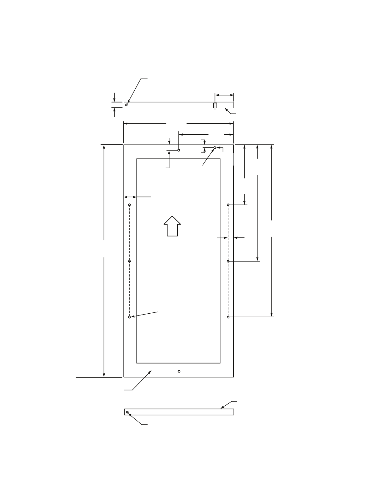
Pre-drilled pilot holes -
8 places
22-1/2”
(57.2 cm)
TYP
1
5-5/32”
(38.5 cm)
T
YP
7
-13/16”
(19.8 cm)
T
YP
23/32”
(1.8 cm)
TYP
1-23/32” (4.4 cm)
min. width to cover
d
oor extrusion
30-5/16”
(77.0 cm)
TYP
23/32”
(
1.8 cm)
TYP
1
5/32”
(
1.2 cm)
1
4-5/16”
(
36.4 cm)
7-5/32”
(18.2 cm)
Mounting Surface
(non-face) side
Mounting Surface
(non-face) side
M
ounting Surface
(non-face) side
1/4” x 3/8” deep hinge screw clearance hole. Locate and drill using
door hinge hole after the door has been aligned to the unit and when
the wood is positioned on door.
M
in. 5/8” (1.7 cm)
Max. 3/4” (1.9 cm)
1/4” x 3/8” deep hinge screw clearance hole. Locate and drill using
door hinge hole after the door has been aligned to the unit and when
the wood is positioned on door.
3
-7/32”
(8.1cm)
1
3/16”
(2.1 cm)
c
ounterbore 7/16”
(1.1 cm) deep
15/32”
(1.2 cm)
D
iameter
Hole
FOR 3-1/2” TOE KICK
(COVERS THE ENTIRE DOOR EXTRUSION - LEFT HINGE)
Selecting and Preparing the Wood Frame - 15”W. DFUW Model
11
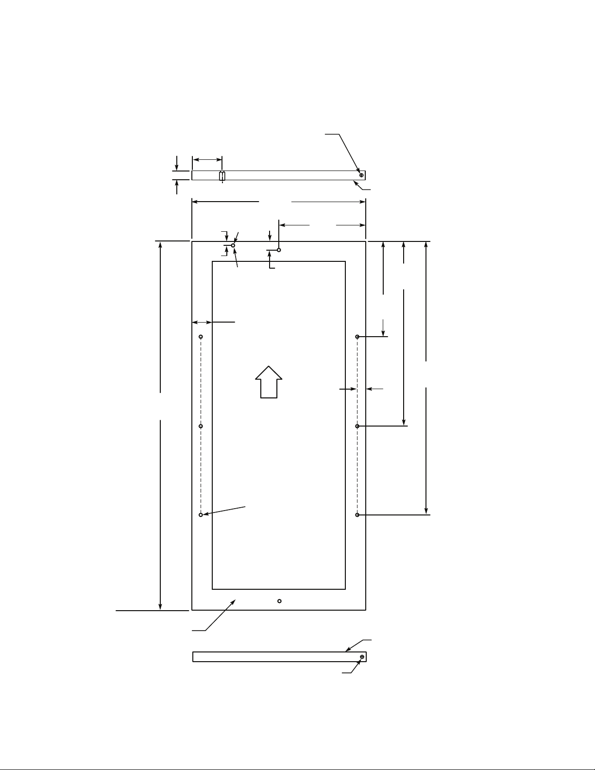
FOR 3-1/2” TOE KICK
(
COVERS THE ENTIRE DOOR EXTRUSION - RIGHT HINGE)
Selecting and Preparing the Wood Frame - 15”W. DFUW Model
B
A
C
K
V
I
E
W
O
F
O
V
E
R
L
A
Y
P
A
N
E
L
T
OP
OF
DOOR
Pre-drilled pilot holes -
8 places
22-1/2”
(57.2 cm)
TYP
1
5-5/32”
(
38.5 cm)
TYP
7
-13/16”
(19.8 cm)
T
YP
23/32”
(1.8 cm)
TYP
1
-23/32” (4.4 cm)
min. width to cover
door extrusion
30-5/16”
(77.0 cm)
TYP
23/32”
(
1.8 cm)
TYP
15/32”
(1.2 cm)
14-5/16”
(36.4 cm)
7-5/32”
(18.2 cm)
Mounting Surface
(non-face) side
Mounting Surface
(non-face) side
1/4” x 3/8” deep hinge screw clearance hole. Locate and
drill using door hinge hole after the door has been aligned
to the unit and when the wood is positioned on door.
1/4” x 3/8” deep hinge screw clearance hole. Locate and drill
using door hinge hole after the door has been aligned to the
unit and when the wood is positioned on door.
M
in. 5/8” (1.7 cm)
Max. 3/4” (1.9 cm)
3-7/32”
(
8.1cm)
Mounting Surface
(
non-face) side
1
5/32”
(1.2 cm)
D
iameter
Hole
13/16”
(
2.1 cm)
c
ounterbore
7/16” (1.1 cm)
deep
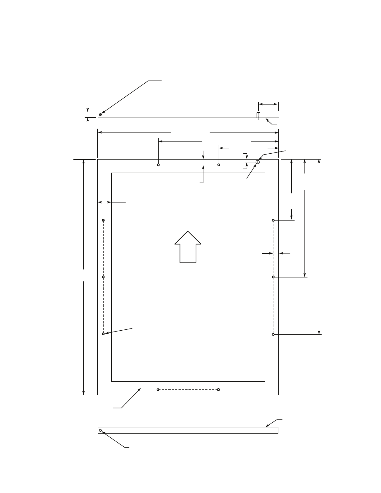
12
30-5/16”
(77.0 cm)
Mounting Surface
(non-face) side
Mounting Surface
(non-face) side
1/4” x 3/8” deep hinge screw clearance hole. Locate and
drill using door hinge hole after the door has been aligned
to the unit and when the wood is positioned on door.
Pre-drilled pilot holes -
10 places
B
A
C
K
V
I
E
W
O
F
O
V
E
R
L
A
Y
P
A
N
E
L
TOP
OF
DOOR
1
-23/32” (4.4 cm)
min. width to cover
d
oor extrusion
23/32”
(1.8 cm)
TYP
2
3/32”
(1.8 cm)
T
YP
1
3/16”
(2.1 cm)
c
ounterbore
7/16” (1.1 cm)
deep
22-1/2”
(57.2 cm)
TYP
1
5-5/32”
(38.5 cm)
TYP
7-13/16”
(19.8 cm)
T
YP
15/32”
(
1.2 cm)
1
5/32” (1.2 cm)
Diameter Hole
7
-13/16” (19.8 cm)
15-5/8” (39.7 cm) TYP
23-7/16” (59.5 cm)
1/4” x 3/8” deep hinge screw clearance hole. Locate and drill
using door hinge hole after the door has been aligned to the
unit and when the wood is positioned on door.
Min. 5/8” (1.7 cm)
M
ax. 3/4” (1.9 cm)
3
-7/32”
(
8.1cm)
Mounting Surface
(
non-face) side
FOR 3-1/2” TOE KICK
(COVERS THE ENTIRE DOOR EXTRUSION - LEFT HINGE)
Selecting and Preparing the Wood Frame - 24”W. DFUW Model
13
30-5/16”
(77.0 cm)
Mounting Surface
(non-face) side
Mounting Surface
(non-face) side
1/4” x 3/8” deep hinge screw clearance hole. Locate and
drill using door hinge hole after the door has been aligned
to the unit and when the wood is positioned on door.
Pre-drilled pilot holes -
10 places
B
A
C
K
V
I
E
W
O
F
O
V
E
R
L
A
Y
P
A
N
E
L
TOP
OF
DOOR
1
-23/32” (4.4 cm)
min. width to cover
d
oor extrusion
23/32”
(1.8 cm)
TYP
23/32”
(
1.8 cm)
TYP
1
3/16” (2.1 cm)
counterbore
7
/16” (1.1 cm)
deep
22-1/2”
(57.2 cm)
TYP
15-5/32”
(
38.5 cm)
TYP
7-13/16”
(19.8 cm)
T
YP
15/32”
(
1.2 cm)
1
5/32”
(1.2 cm)
D
iameter Hole
7
-13/16” (19.8 cm)
1
5-5/8” (39.7 cm) TYP
23-7/16” (59.5 cm)
1/4” x 3/8” deep hinge screw clearance hole. Locate and drill
using door hinge hole after the door has been aligned to the
unit and when the wood is positioned on door.
Min. 5/8” (1.7 cm)
M
ax. 3/4” (1.9 cm)
3-7/32”
(
8.1cm)
Mounting Surface
(
non-face) side
FOR 3-1/2” TOE KICK
(COVERS THE ENTIRE DOOR EXTRUSION - RIGHT HINGE)
Selecting and Preparing the Wood Frame - 24”W. DFUW Model
14
Attaching the Wood Frame to the Door - DFUW Model
1. If the door is attached to the unit, remove by unscrewing the top Allen head set screw at the top hinge. Remove the door by
angling the door off of the bottom hinge pin.
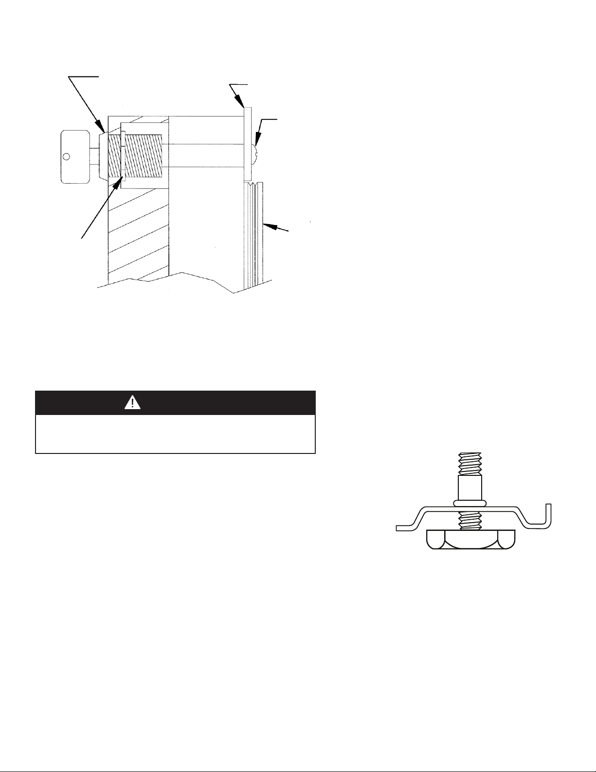
2. Install the supplied lock body into the wood panel. Secure the lock body by using the supplied 15mm lock retaining nut. Screw
the retaining nut onto the lock body’s threaded section. Make sure the lock’s key slot is vertical, then tighten the nut with a
15mm deep well socket.
3. Peel back the door gasket to expose the screw holes and lock location hole.
4. Set the wood frame flush to the front of the door in the desired location. Clamp the wood frame to the door if necessary.
Check to make sure the back of the lock in the wood frame lines up with the hole in the door.
5. Insert the wood screws through the back of the door into the pilot holes in the wood frame and tighten.
6. Assemble the door lock’s Phillips head screw, lock extension, and lock cam. Mount them to the back of the lock body. The cam
should be oriented vertically. Tighten the Phillips head screw to secure the lock assembly.
7. Reinstall the door gasket by pressing into the door channel. Make certain the corners are inserted fully. Insert the key into the
lock and make sure lock operates properly.
8. Install the door to the unit. Use the supplied plastic washer as shown in the figure below.
9. Realigning the door may be necessary. Any final door adjustments can be made using a 1/8” Allen head driver to adjust the
door’s hinges. (See figure below.)
10. Attach the door to the unit by reversing step number 1 above.
11. Insert the key into the lock and verify that the lock cam works properly with the catch bracket on the cabinet front.
Attaching the Handle
Attach the handle of your choice by drilling mounting holes through panel. Countersink or counterbore holes from
backside of panel for handle screw heads to be flush.
Hinge Hardware Installation Details
(2) NYLON
HARDWARE
COMPONENTS
AT TOP HINGE
TOP HINGE COVER
WOOD FRAME
DOOR HINGE
SHOULDER
BUSHING
5/8” X 7/32 ID
WASHER
BOTTOM HINGE COVER
3/4” OD X 7/16”
ID WASHER
3/4” OD X 1/4”
ID WASHER
C
ABINET HINGE
(3) NYLON HARDWARE
COMPONENTS AT
BOTTOM HINGE
DOOR HINGE
WOOD FRAME
SHOULDER
BUSHING
ATTACHED WOOD
FRAME
REAR OF DOOR
MAGNETIC
DOOR GASKET
BOTTOM
OF DOOR
1/8” ALLEN HEAD SCREWS
FOR HINGE ADJUSTMENT
Ø 3/8” CLEARANCE
HOLES FOR FRAME
WOOD SCREWS -
10 HOLES
DOOR HINGE
ADJUSTMENT SCREWS
CAUTION
Door can become disengaged if washers are not installed.
CAUTION
Door may not swing properly if all nylon components are not
installed as shown.
15
Lock Installation Details
L
L
o
o
c
c
k
k
B
B
o
o
d
d
y
y
LLoocckk CCaamm
P
P
h
h
i
i
l
l
l
l
i
i
p
p
s
s
S
S
c
c
r
r
e
e
w
w
L
L
o
o
c
c
k
k
E
E
x
x
t
t
e
e
n
n
s
s
i
i
o
o
n
n
L
L
o
o
c
c
k
k
R
R
e
e
t
t
a
a
i
i
n
n
e
e
r
r
N
N
u
u
t
t
KKEEYY
D
D
o
o
o
o
r
r
G
G
a
a
s
s
k
k
e
e
t
t
G
G
ll
aa
ss
ss
DD
oo
o
o
rr
WW
oo
oo
dd
PP
aa
nn
ee
ll
LEG LEVELER INSTALLATION
RReeaadd BBeeffoorree IInnssttaalllliinngg LLeegg LLeevveelleerrss
1. Four leveling legs are pre-installed in the base of the unit at the factory.
2. The unit should be leveled from front to back and side to side. If floor
conditions do not allow the unit to sit level, adjust the leg levelers by turning
the required leg leveler counter-clockwise to increase the height and clockwise
to reduce the height.
WARNING
Do not lay unit on top, side, back, or front. If unit is accidentally laid in
any position other than right side up, then the unit must remain in the
upright position for at least 24 hours before plugging the unit in.
16
FINAL PREPARATION
1. Some stainless steel parts may have a plastic protective wrap which must be peeled off. The interior of the wine
cellar should be washed thoroughly with hot, soapy water, rinsed and wiped dry to remove film residue and any
installation dust or debris before being used. Solutions stronger than soap and water are rarely needed.
2. All stainless steel parts should be wiped with hot soapy water. If buildup occurs, do not use steel wool, abrasive
cloths, cleaners, or powders. If it is necessary to scrape stainless steel to remove encrusted materials, soak with hot,
wet cloths to loosen the material, then use a wood or nylon scraper. Do not use a metal knife, spatula, or any other
metal tool to scrape stainless steel; scratches are almost impossible to remove.
ELECTRICAL CONNECTION
E
lectrical Requirements
A
115 volt, 60 Hz, AC only 15 amp fused electrical supply is required. (A time
d
elay fuse or circuit breaker is recommended.) It is recommended that a
separate circuit, serving only this appliance, be provided.
•ELECTRICAL GROUND IS REQUIRED ON THIS APPLIANCE.
•DO NOT UNDER ANY CIRCUMSTANCES REMOVE THE POWER SUPPLY
CORD GROUND PLUG.
•DO NOT USE AN EXTENSION CORD.
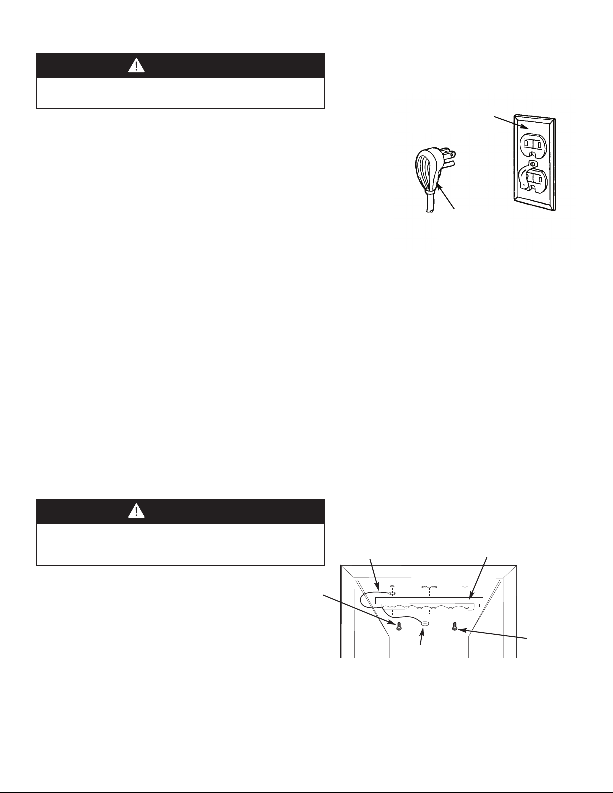
Recommended Grounding Methods
For your personal safety, this refrigeration product must be grounded. This appliance is equipped with a 5’ power
supply cord having a 3-prong grounding plug. To minimize possible shock hazard, the cord must be plugged into a
mating 3-prong grounding type wall receptacle grounded in accordance with the National Electrical Code and local
codes and ordinances. If the circuit does not have a grounding type receptacle, it is the responsibility and obligation of
the customer to exchange the existing receptacle in accordance with the National Electrical Code and applicable local
codes and ordinances. The third ground plug SHOULD NOT, under any circumstances, be cut or removed. All UL listed
refrigerated products are equipped with this type of plug.
WARNING
ELECTRICAL SHOCK HAZARD
Failure to follow these instructions could result in fire or electrical shock.
Grounding type
w
all receptacle
Power Supply
with 3-prong
grounding plug
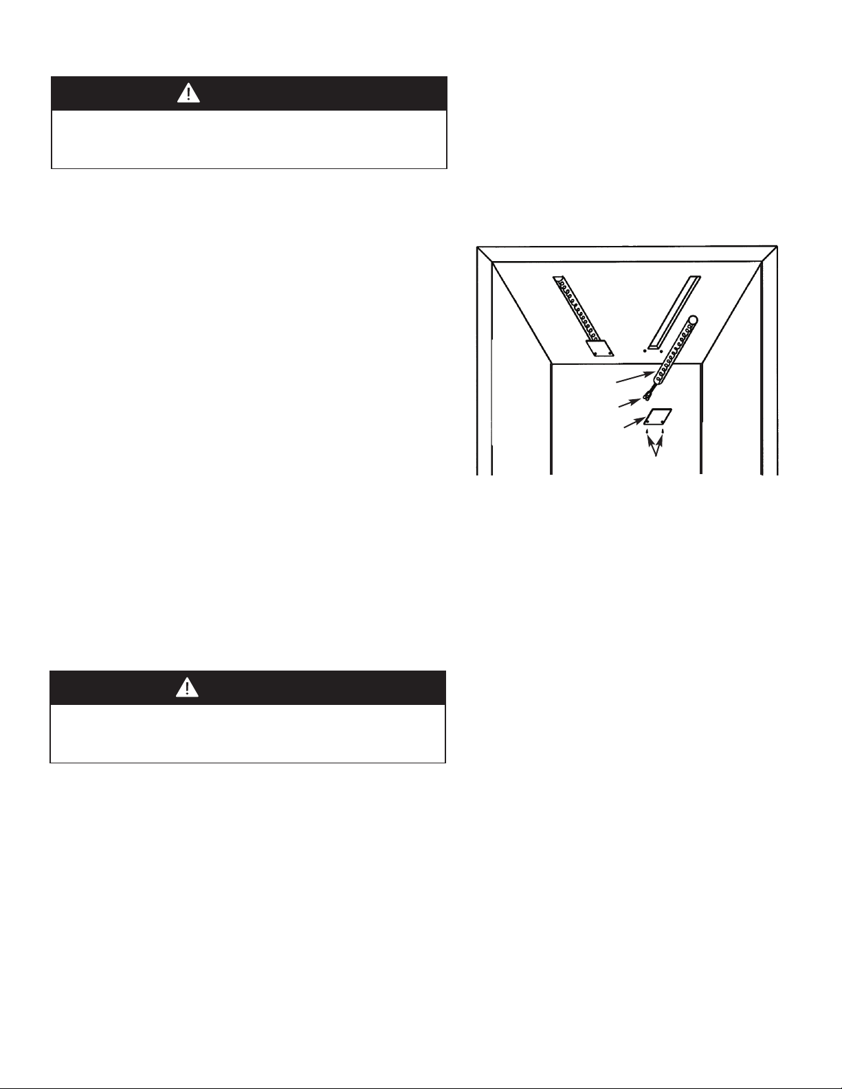
LIGHT ASSEMBLY REPLACEMENT - 15” W. Models
NOTE: Please contact your local Viking Range
Corporation parts distributor or dealer to order a
new light assembly.
To replace the light, first disconnect the unit’s power
cord. Next, remove both the green ground wire
screw located on the left of the light assembly and
the other screw located on the right of the light assembly with a 5-16” hex head screwdriver. (See drawing). Unplug
the light unit and remove complete light assembly.
To install the new light assembly, screw in the green ground wire screw and the screw located on the right with a 5/16”
hex head screwdriver and plug the light unit in.
Plug
Hex head
screw
Light
assembly
Green
ground wire
Hex head
screw
DANGER
ELECTRICAL SHOCK HAZARD
Failure to to disconnect the power cord when changing the light tube,
could result in fire or electrical shock.
17
LIGHT TUBE REPLACEMENT - 24” W. Dual Zone Models
NOTE: Please contact your Viking Range Corporation parts distributor or dealer to order new light tubes. Use only
approved replacement light tubes from your dealer or manufacturer.
This product uses two light tubes to illuminate the interior of the wine cellar. There is one light tube located behind the
control housing in the the upper compartment and one light tube attached to the underside of the cabinet divider in
the lower compartment.
Use replacement instructions and drawing from the 15”W. Models for this Dual Zone product.
DANGER
ELECTRICAL SHOCK HAZARD
Failure to to disconnect the power cord when changing the light tube,
could result in fire or electrical shock.
LIGHT TUBE REPLACEMENT - 24” W. Single Zone Models
N
OTE: Please contact your Viking Range Corporation parts distributor or dealer to order new light tubes. Use only
a
pproved replacement light tubes from your dealer or manufacturer.
This product uses two 6-watt light tubes to illuminate the interior
of the wine cellar. The light tubes are very reliable electrical
components, but should either or both light tubes not function
properly, please call your local dealer for replacement light tubes.
To replace the light tube:
•Use a small Phillips head screwdriver to remove the two screws
holding the cover plate over the back section of the light tube.
Set the screws and cover plate aside for re-assembly later.
•Using a small flat-blade screwdriver, gently lever the front section
of the light tube down to allow it to be pulled clear of the light
housing. Disconnect the two insulated electrical connectors from
the cabinet's electrical cable and discard the old light tube.
•Reconnect the insulated electrical connector of the new light tube
to the cabinet's electrical cable connectors. Make sure they are
secure and fully inserted.
•Carefully realign the light tube's electrical terminals back into the rear of the light enclosure channel making sure not
to crimp them. Gently insert the light tube along the length of the light enclosure channel. Press the light tube gently
into the light enclosure channel. Only a small part of the light tube should project below the ceiling of the unit. DO
NOT USE A HAMMER TO FIT THE LIGHT TUBE.
•Place the light tube terminal cover plate back in its original position on the light enclosure's flange. Re-use the original
two screws to secure the cover in place. Plug the unit into the electrical socket. Check to see if the light tubes operate
properly.
Light tube
Connectors
Cover plate
Screws
DANGER
ELECTRICAL SHOCK HAZARD
Failure to to disconnect the power cord when changing the light tube,
could result in fire or electrical shock.
18
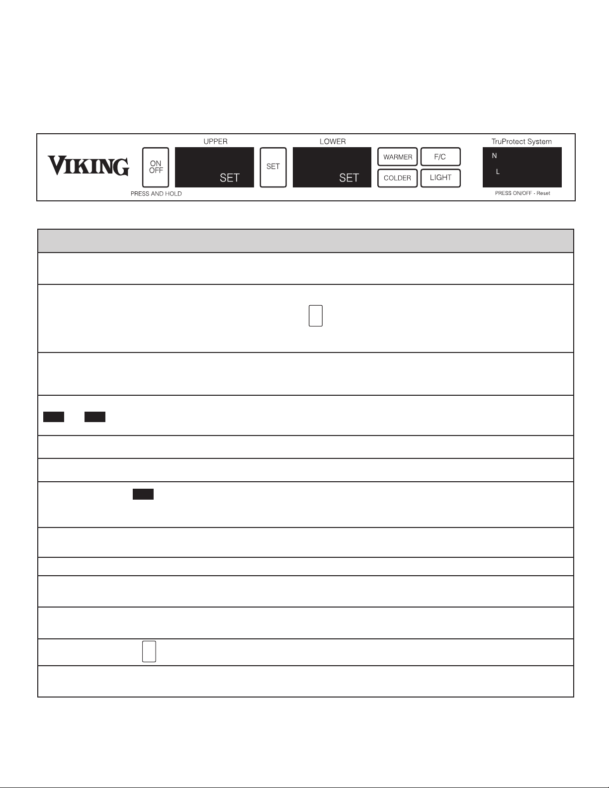
SETTING THE CONTROLS - SINGLE ZONE
The temperature of the wine cellar ranges from 40ºF (4ºC) to 65°F (18ºC).
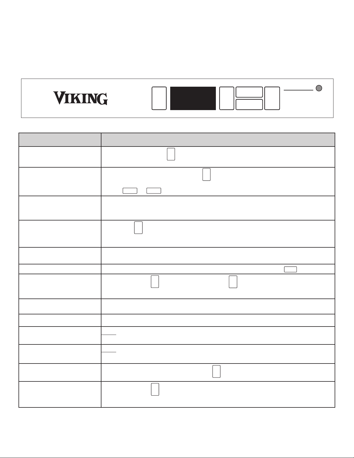
Solid Door Single Zone Models:
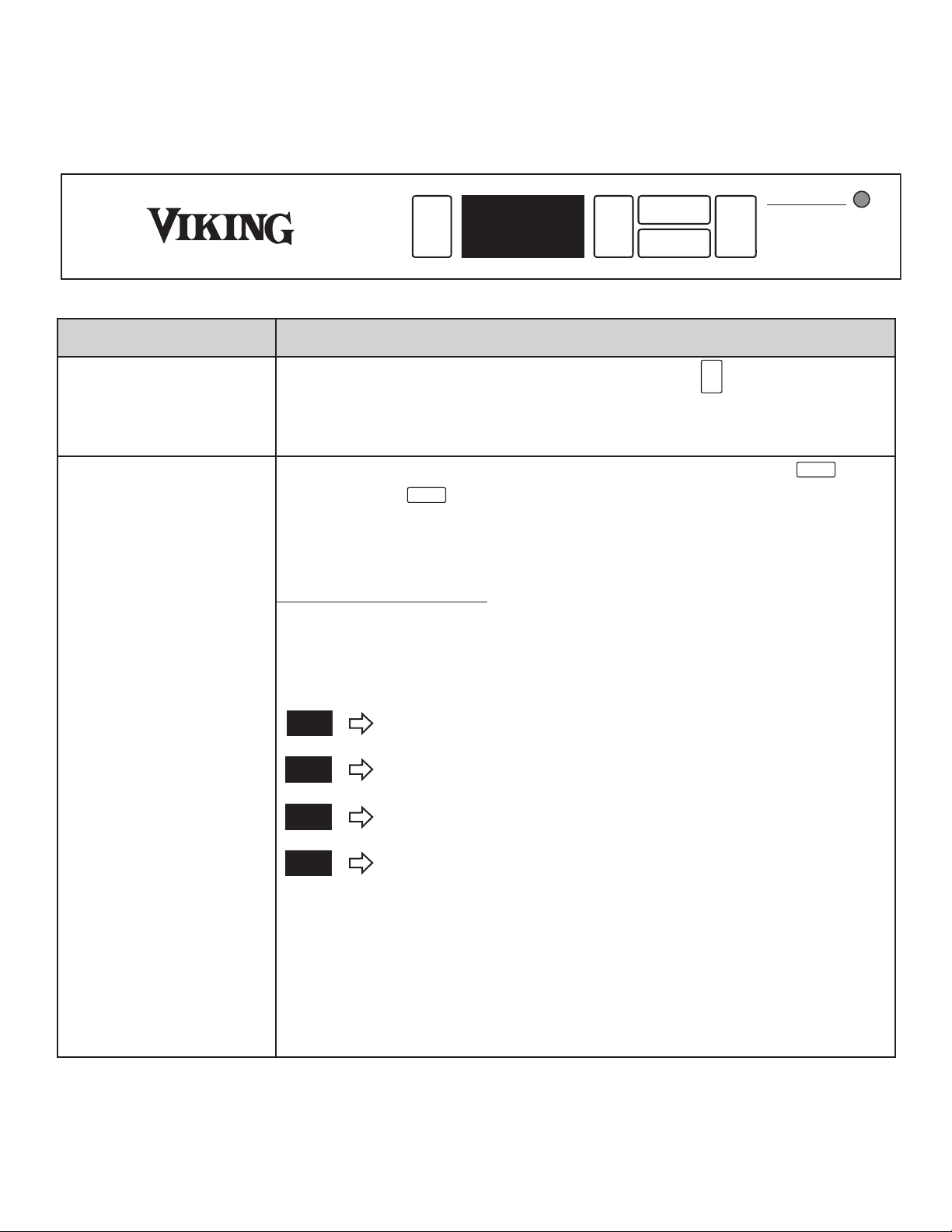
TruProtect™ “Basic” Function “Quick” Reference
O
N
OFF
SET
WARMER
C
OLDER
F
/C
PRESS AND HOLD
POWER FAILURE - Flashing Amber
HIGH/LOW TEMP - Red
PRESS ON/OFF - Reset
A
LARMS OFF - Steady Amber
T
ruProtect System
5
5
˚
F
FFuunnccttiioonn FFuunnccttiioonn AAcccceessss
TTuurrnn UUnniitt OOnn && OOffff
PPrreessssiinngg aanndd hhoollddiinngg tthhee kkeeyy ffoorr 55--sseeccoonnddss wwiillll ttuurrnn tthhee uunniitt ““OONN”” oorr ““OOFFFF””..
AAddjjuusstt TTeemmppeerraattuurree SSeett--PPooiinntt TToo aaddjjuusstt tteemmppeerraattuurree sseett--ppooiinntt,, ttoouucchh kkeeyyppaadd aanndd ccuurrrreenntt sseett--ppooiinntt wwiillll bbee ddiissppllaayyeedd..
UUssee tthhee oorr kkeeyyppaaddss ttoo aaddjjuusstt sseett--ppooiinntt tteemmppeerraattuurree..
DDiissppllaayy ““AAccttuuaall”” TTeemmppeerraattuurree DDiissppllaayy rreepprreesseennttss ““rreeaall--ttiimmee”” mmoonniittoorriinngg ooff tthhee ccoommppaarrttmmeennttss ssttoorreedd wwiinnee aanndd//oorr
ccoonntteennttss.. SSoommee tteemmppeerraattuurree fflluuccttuuaattiioonn aarroouunndd yyoouurr ddeessiirreedd sseett--ppooiinntt iiss nnoorrmmaall..
SSeelleecctt ººFF oorr ººCC DDiissppllaayy
PPrreessssiinngg tthhee kkeeyyppaadd wwiillll ttooggggllee tthhee ddiissppllaayy bbeettwweeeenn FFaahhrreennhheeiitt aanndd CCeennttiiggrraaddee
tteemmppeerraattuurree ddiissppllaayy..
BBllaacckk--OOuutt MMooddee DDiissppllaayy aauuttoommaattiiccaallllyy sshhuuttss ooffff wwhheenn ddoooorr iiss cclloosseedd..
DDiissppllaayy LLiigghhttiinngg DDiissppllaayy LLiigghhttiinngg ccaann bbee eennaabblleedd wwiitthh tthhee ddoooorr cclloosseedd bbyy pprreessssiinngg tthhee kkeeyyppaadd..
SSaabbbbaatthh MMooddee
PPrreessss aanndd hhoolldd tthhee kkeeyyppaadd wwhhiillee pprreessssiinngg tthhee kkeeyyppaadd ffoouurr ((44)) ttiimmeess..
TTrruuPPrrootteecctt
™
SSyysstteemm SSyysstteemm mmoonniittoorriinngg iiss aauuttoommaattiiccaallllyy eennaabblleedd uunnlleessss ssyysstteemm hhaass bbeeeenn ddiissaabblleedd.. ((SSeeee
bbeellooww..))
DDoooorr AAjjaarr AAllaarrmm
NN//AA
HHiigghh//LLooww TTeemmpp AAllaarrmm
NNoottee:: AAllaarrmm mmaayy ooccccuurr wwhheenn cchhaannggiinngg sseett--ppooiinnttss iinn eexxcceessss ooff 1100ººFF,, aanndd//oorr hhiigghh uussaaggee,,
tthhiiss iiss nnoorrmmaall..
PPoowweerr FFaaiilluurree AAllaarrmm NNoottee:: AAllaarrmm wwiillll ooccccuurr uuppoonn iinniittiiaall iinnssttaallllaattiioonn,, ssiinnccee uunniitt wwaass rruunn aatt ffaaccttoorryy ttoo vveerriiffyy
qquuaalliittyy,, tthhiiss iiss nnoorrmmaall..
RReesseett AAllaarrmmss
CClloossee ddoooorr ttoo rreesseett DDoooorr AAjjaarr aallaarrmm.. PPrreessss kkeeyyppaadd ttoo rreesseett aallll ootthheerr aallaarrmmss..
DDiissaabbllee//EEnnaabbllee TTrruuPPrrootteecctt
™
PPrreessss aanndd hhoolldd tthhee kkeeyyppaadd ffoorr 55--sseeccoonnddss ttoo ““ddiissaabbllee”” oorr ““eennaabbllee”” TTrruuPPrrootteecctt
™
SSyysstteemm..
ON
OFF
SET
WARMER
COLDER
˚
F/C
LIGHT
5
5
˚
F
1
3
˚
C
38
˚
F
4
˚
C
SA
ON
OFF
SET
WARMER
COLDER
˚
F/C
LIGHT
5
5
˚
F
1
3
˚
C
38
˚
F
4
˚
C
SA
ON
OFF
SET
WARMER
COLDER
˚
F/C
LIGHT
5
5
˚
F
1
3
˚
C
38
˚
F
4
˚
C
SA
ON
OFF
SET
WARMER
COLDER
˚
F/C
LIGHT
5
5
˚
F
1
3
˚
C
38
˚
F
4
˚
C
SA
ON
OFF
SET
WARMER
COLDER
˚
F/C
LIGHT
5
5
˚
F
1
3
˚
C
38
˚
F
4
˚
C
SA
ON
OFF
SET
WARMER
COLDER
˚
F/C
LIGHT
5
5
˚
F
1
3
˚
C
38
˚
F
4
˚
C
SA
ON
OFF
SET
WARMER
COLDER
˚
F/C
LIGHT
5
5
˚
F
1
3
˚
C
38
˚
F
4
˚
C
SA
ON
OFF
SET
WARMER
COLDER
˚
F/C
LIGHT
5
5
˚
F
1
3
˚
C
38
˚
F
4
˚
C
SA
ON
OFF
SET
WARMER
COLDER
˚
F/C
LIGHT
5
5
˚
F
1
3
˚
C
38
˚
F
4
˚
C
SA
ON
OFF
SET
WARMER
COLDER
˚
F/C
LIGHT
5
5
˚
F
1
3
˚
C
38
˚
F
4
˚
C
SA
19
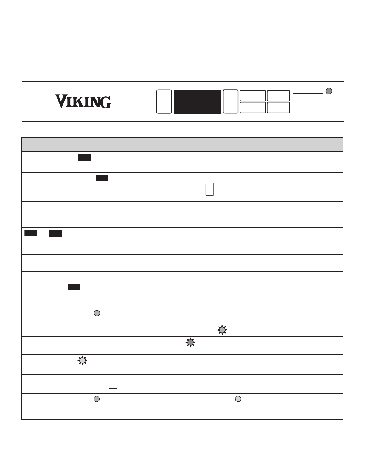
Glass Door Single Zone Models:
O
N
OFF
SET
PRESS AND HOLD
P
OWER FAILURE - Flashing Amber
HIGH/LOW TEMP - Red
P
RESS ON/OFF - Reset
ALARMS OFF - Steady Amber
TruProtect System
WARMER
C
OLDER
˚
F/C
LIGHT
5
5
˚
F
55˚
CCoonnttrrooll CCoonnffiirrmmaattiioonn//CCoommmmeenntt
DDiissppllaayy wwiillll bbee bbllaannkk wwhheenn rreeffrriiggeerraattiioonn ssyytteemm iiss ooffff.. LLiigghhttss wwiillll ssttiillll ffuunnccttiioonn,, bbuutt wwiillll ttiimmee--oouutt 1155 mmiinnuutteess aafftteerr
eeaacchh aaccttiivvaattiioonn,, iiff ddoooorr iiss lleefftt ooppeenn oorr ddiissppllaayy lliigghhttiinngg iiss oonn,, ttoo pprreevveenntt oovveerrhheeaattiinngg..
““SSeett”” wwiillll aappppeeaarr iinn ddiissppllaayy wwhheenn iinn sseett--ppooiinntt mmooddee.. ““SSEETT”” mmooddee wwiillll aauuttoommaattiiccaallllyy ttiimmee--oouutt iinn 1100 sseeccoonnddss iiff nnoo
kkeeyyppaadd aaccttiivviittyy ooccccuurrss,, oorr yyoouu mmaayy eexxiitt ““SSEETT”” mmooddee bbyy pprreessssiinngg tthhee kkeeyyppaadd aa sseeccoonndd ttiimmee..
TTeemmppeerraattuurree vvaarriiaattiioonn iinn ““ccoommppaarrttmmeenntt aaiirr””,, aabboovvee aanndd bbeellooww sseett--ppooiinntt,, iiss aa nnoorrmmaall eeffffeecctt ooff rreeffrriiggeerraattiioonn ssyysstteemm
ccyycclliinngg oonn aanndd ooffff.. SSttoorreedd iitteemmss wwiillll nnoott eexxppeerriieennccee tthhee ffuullll tteemmppeerraattuurree sswwiinngg ooff tthhee ccoommppaarrttmmeenntt aaiirr dduuee ttoo tthhee
ddaammppeenniinngg eeffffeecctt ooff tthheeiirr tthheerrmmaall mmaassss..
==
IInn aaddddiittiioonn,, tthhee ccoonnttrrooll ppaanneell iiss hhiiddddeenn wwhheenn ddoooorr iiss cclloosseedd..
OOppttiioonn aavvaaiillaabbllee oonn GGllaassss DDoooorr MMooddeellss oonnllyy..
DDiissppllaayy wwiillll ffllaasshh ttoo ccoonnffiirrmm yyoouurr sseelleeccttiioonn,, tthheenn uunniitt wwiillll eenntteerr SSaabbbbaatthh MMooddee.. TThhee ddiissppllaayy,, aauuddiibbllee aallaarrmmss,, LLEEDD
aanndd lliigghhttss wwiillll bbee ddiissaabblleedd.. SSaabbbbaatthh MMooddee wwiillll aauuttoommaattiiccaallllyy ttiimmee--oouutt iinn 3366 hhoouurrss,, oorr ccaann bbee eexxiitteedd bbyy rreeppeeaattiinngg tthhee
eennaabbllee kkeeyyppaadd rroouuttiinnee..
LLEEDD ddiissppllaayyss sstteeaaddyy ggrreeeenn wwhheenn TTrruuPPrrootteecctt
™
iiss eennaabblleedd..
AAuuddiibbllee aallaarrmm wwiillll ssoouunndd 33--ttiimmeess eevveerryy 3300--sseeccoonnddss,, LLEEDD wwiillll ffllaasshh ggrreeeenn..
AAllaarrmm wwiillll ssoouunndd 66--ttiimmeess eevveerryy mmiinnuuttee aanndd LLEEDD wwiillll ffllaasshh rreedd iiff pprroodduucctt tteemmppeerraattuurree eexxccuurrssiioonnss ooccccuurr ffoorr aa dduurraattiioonn
oouuttssiiddee aacccceeppttaabbllee lliimmiittss..
LLEEDD wwiillll ffllaasshh aammbbeerr wwhheenneevveerr ppoowweerr iiss iinntteerrrruupptteedd ttoo uunniitt.. NNoo aauuddiibbllee ssiiggnnaall..
NNoottee tthhaatt aalltthhoouugghh pprreessssiinngg tthhee kkeeyyppaadd wwiillll rreesseett tthhee aallaarrmmss,, tthhee aallaarrmm wwiillll rreessuummee iiff tthhee ““aallaarrmm ccoonnddiittiioonn”” ssttiillll
eexxiissttss..
LLEEDD ddiissppllaayyss sstteeaaddyy ggrreeeenn wwhheenn aallaarrmmss eennaabblleedd.. LLEEDD ddiissppllaayyss sstteeaaddyy aammbbeerr wwhheenn ddiissaabblleedd..
ON
OFF
SET
WARMER
COLDER
˚
F/C
LIGHT
55
˚
F
1
3
˚
C
3
8
˚
F
4
˚
C
SA
ON
OFF
SET
WARMER
COLDER
˚
F/C
LIGHT
5
5
˚
F
1
3
˚
C
38
˚
F
4
˚
C
SA
ON
OFF
SET
WARMER
COLDER
˚
F/C
LIGHT
5
5
˚
F
1
3
˚
C
38
˚
F
4
˚
C
SA
ON
OFF
SET
WARMER
COLDER
˚
F/C
LIGHT
5
5
˚
F
1
3
˚
C
38
˚
F
4
˚
C
SA
ON
OFF
SET
WARMER
COLDER
˚
F/C
LIGHT
5
5
˚
F
1
3
˚
C
38
˚
F
4
˚
C
SA
ON
OFF
SET
WARMER
COLDER
˚
F/C
LIGHT
5
5
˚
F
1
3
˚
C
38
˚
F
4
˚
C
SA
ON
OFF
SET
WARMER
COLDER
˚
F/C
LIGHT
5
5
˚
F
1
3
˚
C
38
˚
F
4
˚
C
SA
ON
OFF
SET
WARMER
COLDER
˚
F/C
LIGHT
5
5
˚
F
1
3
˚
C
38
˚
F
4
˚
C
SA
ON
OFF
SET
WARMER
COLDER
˚
F/C
LIGHT
5
5
˚
F
1
3
˚
C
38
˚
F
4
˚
C
S
A
ON
OFF
SET
WARMER
COLDER
˚
F/C
LIGHT
5
5
˚
F
1
3
˚
C
38
˚
F
4
˚
C
SA
ON
OFF
SET
WARMER
COLDER
˚
F/C
LIGHT
5
5
˚
F
1
3
˚
C
38
˚
F
4
˚
C
S
A
ON
OFF
SET
WARMER
COLDER
˚
F/C
LIGHT
5
5
˚
F
1
3
˚
C
38
˚
F
4
˚
C
SA
ON
OFF
SET
WARMER
COLDER
˚
F/C
LIGHT
5
5
˚
F
1
3
˚
C
38
˚
F
4
˚
C
SA
20
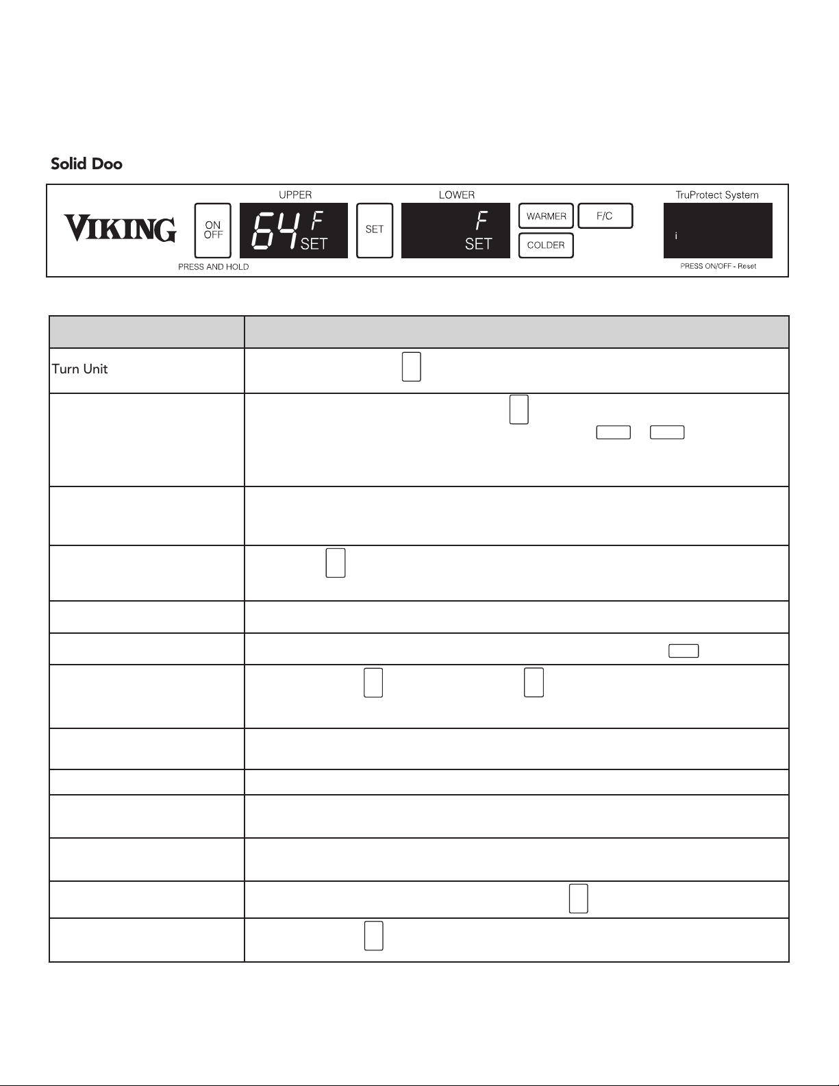
SETTING THE CONTROLS - DUAL ZONE
The temperature of the wine cellar ranges from 40ºF (4ºC) to 65°F (18ºC).
ON
OFF
SET
ON
OFF
Control Confirmation/Comment
SET
WARMER
COLDER
˚
F/C
LIGHT
˚
F/C
SET
=
55û
Place new control here when I get it from Ray
6
4
û
F
4
2
û
F
ON
Hi/Low Temp Upper
Hi/Low Temp Lower
6
4
û
F
4
2
û
F
ON
Hi/Low Temp Upper
Hi/Low Temp Lower
1
3
û
C
5
5
û
F
S
A
Turn Unit On & Off
Adjust Temperature Set-Point
Display “Actual” Temperature
Select °F or °C Display
Black-Out Mode
Display Lighting
Sabbath Mode
TruProtect™ System
Door Ajar Alarm
High/Low Temp Alarm
Power Failure Alarm
Reset Alarms
Disable/Enable TruProtect™
Function
Function Access
Pressing and holding the key for 5-seconds will turn the unit “ON” or “OFF”.
To adjust temperature set-point, press the key. When a compartment is in “SET”
mode, a “SET” icon will be displayed. Pressing either the or keys located
on the display pad will raise or lower the set temperature by one (1) °F or °C (depending
on your setting).
Display represents “real-time” temperature of each compartment’s stored wine and/or
contents. Some minor temperature fluctuation around your desired set-point is normal.
Pressing the key will toggle the display between Fahrenheit and Centigrade
temperature display.
Display automatically shuts off when the door is closed.
Display lighting can be enabled with the door closed by pressing the key.
Press and hold the key while pressing the key four (4) times in seven (7) seconds.
System monitoring is automatically enabled unless system has been shut off (see below).
N/A
NOTE: This alarm may occur when changing set-points in excess of 10 °F, and/or high
usage, this is normal.
NOTE: This alarm may occur upon initial installation since the unit was run at the factory
to verify quality, this is normal.
Close door to reset “DOOR AJAR” Alarm. Press the key to reset all other alarms.
Press and hold the key for five (5) seconds to enable or disable the TruProtect™
System.
Display will be blank when the refrigeration system is off. Lights will still function, but will time-out in 15 minutes after
each activation if door is left open or display lighting is on, to prevent overheating.
“SET” mode will automatically time-out in ten (10) seconds and default to actual content temperature if no keypad
activity occurs, or you may exit “SET” mode by pressing the key until “SET” icon disappears.
Temperature variation in “compartment” air, above and below set-point, is a normal effect of the refrigeration system
cycling on and off. Stored items will not experience the full temperature swing of the compartment air due to the
dampening effect of their thermal mass.
In addition, the control panel is hidden when the door is closed.
Display lighting stays on continuously.
The display will flash to confirm your selection, then the unit will enter Sabbath Mode. The display, audible alarms,
message center and lights will be disabled. Sabbath Mode will automatically time-out in 72 hours, or can be exited by
repeating the enabling process.
TruProtect™ System message center displays a green “ON” when TruProtect™ is enabled and an amber “OFF” when
TruProtect™ is disabled.
An audible alarm will sound 3 times every 30 seconds and the message center will display an amber “DOOR AJAR”.
An audible alarm will sound 6 times every minute and the message center will display a red “HI/LOW TEMP UPPER” or
a red “HI/LOW TEMP LOWER” if product temperature excursions occur for a duration outside acceptable limits.
The message center will display an amber “POWER FAILURE” whenever power is interrupted to the unit. There is no
audible alarm with a power failure.
Although pressing the key resets the alarms, the alarm will resume if the “alarm condition” still exists.
The message center displays a green “ON” when the alarms are enabled.
Solid Door Dual Zone Models:
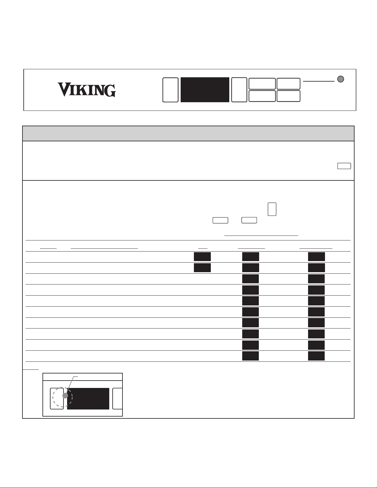
TruProtect™ “Basic” Function “Quick” Reference
21
CCoonnttrrooll CCoonnffiirrmmaattiioonn//CCoommmmeenntt
SET
ON
OFF
==
55û
Place new control here when I get it from Ray
6
4
û
F
4
2
û
F
ON
Hi/Low Temp Upper
Hi/Low Temp Lower
6
4
û
F
4
2
û
F
ON
Hi/Low Temp Upper
Hi/Low Temp Lower
1
3
û
C
5
5
û
F
S
A
Turn Unit On & Off
Adjust Temperature Set-Point
Display “Actual” Temperature
Select °F or °C Display
Black-Out Mode
Display Lighting
Sabbath Mode
TruProtect™ System
Door Ajar Alarm
High/Low Temp Alarm
Power Failure Alarm
Reset Alarms
Disable/Enable TruProtect™
Function
Function Access
Pressing and holding the key for 5-seconds will turn the unit “ON” or “OFF”.
To adjust temperature set-point, press the key. When a compartment is in “SET”
mode, a “SET” icon will be displayed. Pressing either the or keys located
on the display pad will raise or lower the set temperature by one (1) °F or °C (depending
on your setting).
Display represents “real-time” temperature of each compartment’s stored wine and/or
contents. Some minor temperature fluctuation around your desired set-point is normal.
Pressing the key will toggle the display between Fahrenheit and Centigrade
temperature display.
Display automatically shuts off when the door is closed.
Display lighting can be enabled with the door closed by pressing the key.
Press and hold the key while pressing the key four (4) times in seven (7) seconds.
System monitoring is automatically enabled unless system has been shut off (see below).
N/A
NOTE: This alarm may occur when changing set-points in excess of 10 °F, and/or high
usage, this is normal.
NOTE: This alarm may occur upon initial installation since the unit was run at the factory
to verify quality, this is normal.
Close door to reset “DOOR AJAR” Alarm. Press the key to reset all other alarms.
Press and hold the key for five (5) seconds to enable or disable the TruProtect™
System.
Display will be blank when the refrigeration system is off. Lights will still function, but will time-out in 15 minutes after
each activation if door is left open or display lighting is on, to prevent overheating.
“SET” mode will automatically time-out in ten (10) seconds and default to actual content temperature if no keypad
activity occurs, or you may exit “SET” mode by pressing the key until “SET” icon disappears.
Temperature variation in “compartment” air, above and below set-point, is a normal effect of the refrigeration system
cycling on and off. Stored items will not experience the full temperature swing of the compartment air due to the
dampening effect of their thermal mass.
In addition, the control panel is hidden when the door is closed.
Display lighting stays on continuously.
The display will flash to confirm your selection, then the unit will enter Sabbath Mode. The display, audible alarms,
message center and lights will be disabled. Sabbath Mode will automatically time-out in 72 hours, or can be exited by
repeating the enabling process.
TruProtect™ System message center displays a green “ON” when TruProtect™ is enabled and an amber “OFF” when
TruProtect™ is disabled.
An audible alarm will sound 3 times every 30 seconds and the message center will display an amber “DOOR AJAR”.
An audible alarm will sound 6 times every minute and the message center will display a red “HI/LOW TEMP UPPER” or
a red “HI/LOW TEMP LOWER” if product temperature excursions occur for a duration outside acceptable limits.
The message center will display an amber “POWER FAILURE” whenever power is interrupted to the unit. There is no
audible alarm with a power failure.
Although pressing the key resets the alarms, the alarm will resume if the “alarm condition” still exists.
The message center displays a green “ON” when the alarms are enabled.
Glass Door Dual Zone Models:
22
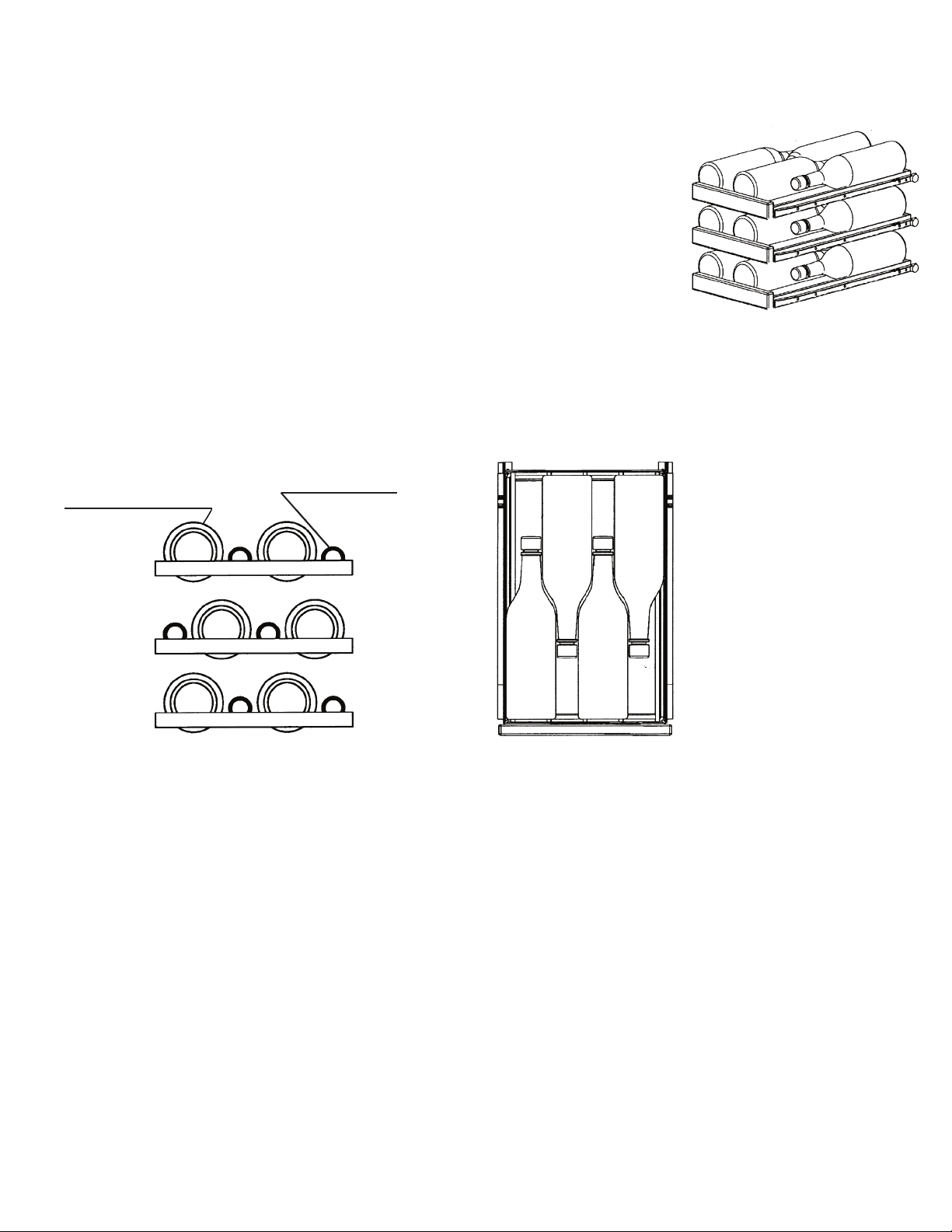
LOADING RECOMMENDATIONS - 15” W. Models
Each of the six roll-out racks hold four bottles. The necks of the bottles alternate front to
back. To aid in loading/unloading, the racks extend up to 14 inches (35.6 cm) to allow
e
asier access to the rear bottles. Bottom racks may be removed for storing “jug’” wines.
Magnums and other large bottles may be stored by removing the rack directly above the
intended storage rack. To remove a rack, first unlock the rack by pushing the lock
backward. The lock is located on the bottom front of each rack. After reinserting the rack,
push the lock forward to lock the rack back into place.
Bottles on the top rack directly under the light will be exposed to slightly higher
temperature when the light is on. Store red wines on the upper racks where the
temperature is higher and white wines on the middle or lower racks where the
temperature is lower. REMEMBER TO TURN OFF THE LIGHT WHEN IT IS NO LONGER
NEEDED.
Store wines intended for everyday use on the front half of the racks where labels are
completely visible and place wines for aging or long term storage in the rear half of the
rack. Pull wine racks out gently to minimize the unsettling of your wine collection.
Avoid pulling out more than one rack at any time to maintain stability.
Roll-out Racks
Since the bottles are not
stacked on top of each
other, the single bottle rack
allows easy view and access
to your inventory without
disturbing other bottles
Front Bottles
(Necks Facing Rear)
Rear Bottles
(Necks Facing Front)
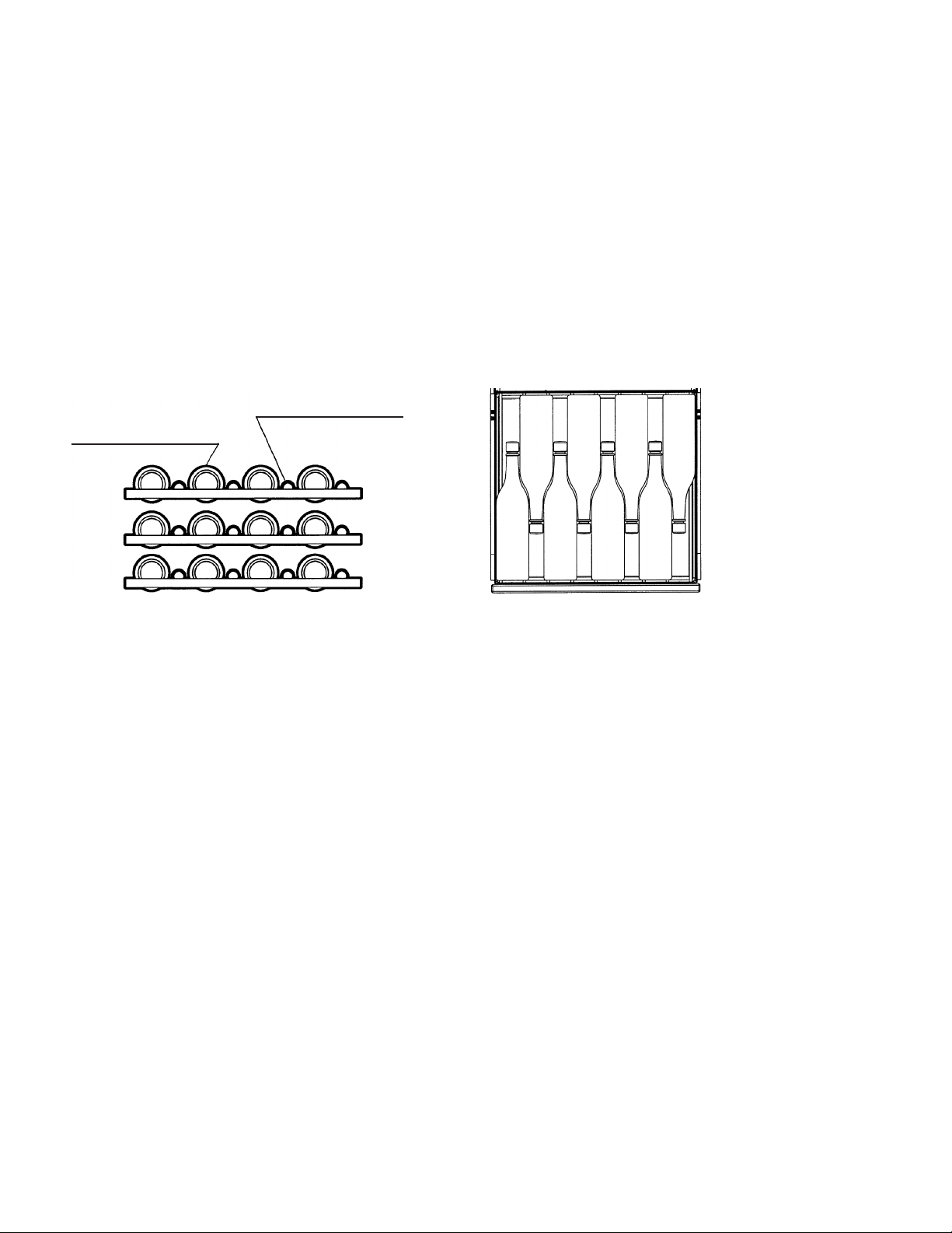
LOADING RECOMMENDATIONS - 24” W. Models
Each of the top five roll-out racks holds 8 bottles with necks alternating front to back. The bottom shelf holds four bottles
for a total of 44 bottles. To aid in the loading and unloading, the racks extend up to 14 inches (35.6 cm) to allow easier
access to rear bottles. Tall bottles should not be loaded on the bottom rack because they may prevent the door from
closing. The bottom rack may be removed for storing “jug” wines. You may store magnum and other large bottles on the
upper right and left positions of the cabinet shelving or on any of the middle racks by removing the rack directly above
them. To remove a rack, first unlock the rack by pushing the lock backward. The lock is located on the bottom front of
each rack. After reinserting the rack, push the lock forward to lock the rack back into place. Position white wines on the
middle or lower racks and red wines on the upper racks.
Bottles on the top rack directly under the light will be exposed to a slightly higher temperature when the light is on.
REMEMBER TO TURN OFF THE LIGHT WHEN IT IS NO LONGER NEEDED.
Store wines intended for everyday use on the front half of the racks where labels are completely visible and place wines
for aging or long term storage in the rear half of the rack. Pull wine racks out gently to minimize the unsettling of your
wine collection. Avoid pulling out more than one rack at any time to maintain stability.
23
LOADING RECOMMENDATIONS - 24” W. Single Zone Models
Each of the top six roll-out racks holds 8 bottles with necks alternating front to back. The bottom wood cradle holds six
bottles for a total of 54 bottles. To aid in the loading and unloading, the racks extend up to 14 inches (35.6 cm) to allow
e
asier access to rear bottles. Tall bottles should not be loaded on the bottom rack because they may prevent the door
from closing. The bottom rack may be removed for storing “jug” wines. You may store magnum and other large bottles
on the upper right and left positions of the cabinet shelving or on any of the middle racks by removing the rack directly
above them. To remove a rack, first unlock the rack by pushing the lock backward. The lock is located on the bottom front
of each rack. After reinserting the rack, push the lock forward to lock the rack back into place. Position white wines on the
m
iddle or lower racks and red wines on the upper racks.
Bottles on the top rack directly under the light will be exposed to a slightly higher temperature when the light is on.
REMEMBER TO TURN OFF THE LIGHT WHEN IT IS NO LONGER NEEDED.
Store wines intended for everyday use on the front half of the racks where labels are completely visible and place wines
for aging or long term storage in the rear half of the rack. Pull wine racks out gently to minimize the unsettling of your
wine collection. Avoid pulling out more than one rack at any time to maintain stability.
Since the bottles are not
stacked on top of each
other, the single bottle
roll-out rack allows easy
view and access of your
inventory without
disturbing other bottles.
Front Bottles
(Necks Facing Rear)
Rear Bottles
(Necks Facing Front)
LOADING RECOMMENDATIONS - 24” W. Dual Zone Models
Both zones can be set for either temperature range, red or white, but for more efficient energy usage and functionality of
the unit, it is better to use the top compartment for reds (warmer) and the bottom compartment for whites (cooler).
Each of the top five roll-out racks holds 8 bottles with necks alternating front to back. The bottom shelf holds four bottles
for a total of 44 bottles. To aid in the loading and unloading, the racks extend up to 14 inches (35.6 cm) to allow easier
access to rear bottles. Tall bottles should not be loaded on the bottom rack because they may prevent the door from
closing. The bottom rack may be removed for storing “jug” wines. You may store magnum and other large bottles on the
upper right and left positions of the cabinet shelving or on any of the middle racks by removing the rack directly above
them. To remove a rack, first unload all wine bottles then pull the rack out and upward. Position white wines on the middle
or lower racks and red wines on the upper racks.
Bottles on the top rack directly under the light and on the rack directly below the separator shelf will be exposed to a
slightly higher temperature when the light is on. REMEMBER TO TURN OFF THE LIGHT WHEN IT IS NO LONGER
NEEDED.
Store wines intended for everyday use on the front half of the racks where labels are completely visible and place wines
for aging or long term storage in the rear half of the rack. Pull wine racks out gently to minimize the unsettling of your
wine collection. Avoid pulling out more than one rack at any time to maintain stability.

24
CLEANING AND MAINTENANCE
A
ny piece of equipment works better and lasts longer when maintained properly and kept clean.
Condenser
The condenser tubing inside the cabinet does not require frequent cleaning; however, satisfactory cooling depends on
adequate ventilation over the coils. Be sure that nothing obstructs the required air flow openings in front of the cabinet.
S
piders and insects can nest in and around the wine cellar causing damage to the unit. Frequently brush or vacuum lint
and dirt from the condenser coils for efficient performance by unscrewing the grill on the bottom front of cabinet.
Cabinet
The cabinet can be washed with mild soap and water and thoroughly rinsed with clear water. NEVER use abrasive
scouring powders.
Interior
Wash interior compartment with mild soap and water. DO NOT USE abrasive powder, solvent, polish cleaner or
undiluted detergent.
Stainless Steel Parts
All stainless steel parts should be wiped regularly with hot soapy water. Use a liquid cleaner designed for stainless steel
when soapy water will not do the job. DO NOT USE steel wool, abrasive cloths, cleansers, or powders. DO NOT
permit citrus or tomato juice to remain on stainless steel surfaces, as citric acid will permanently discolor stainless steel.
Brass Parts
CAUTION: All brass parts are coated with an epoxy coating. DO NOT USE BRASS OR ABRASIVE CLEANERS ON
THE BRASS PARTS. All brass parts should be wiped regularly with hot soapy water. When hot soapy water will not do
the job, use every day non-abrasive household cleaners.
Glass Door
Use a glass cleaner or mild soap and water with a soft cloth to clean the glass door. DO NOT USE any abrasive
powders. On full overlay models, use caution when cleaning near logo area.
Painted Surfaces
Wash with warm soapy water. DO NOT USE steel wool, abrasive cleansers, ammonia, acids or commercial oven
cleaners which may damage the finish.
Door Gasket
The vinyl gasket may be cleaned with mild soap and water, a baking soda and water solution, or a mild scouring
powder.
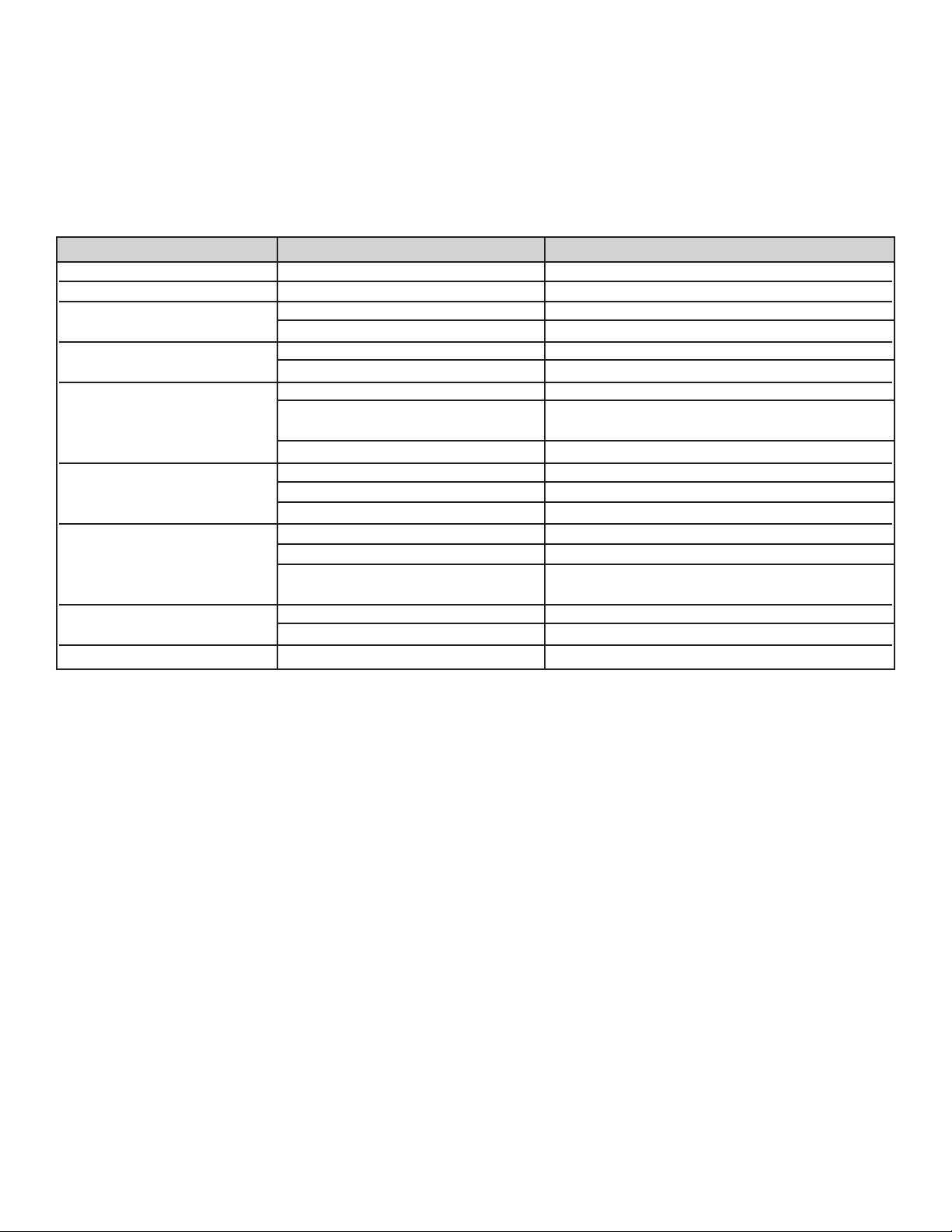
25
Odor in cabinet •Unit interior needs cleaning. •Clean inside of unit.
Noisy operation •Unit not level. •Adjust leveling legs.
Unit vibrates. •Unit not level. •Adjust leveling legs.
•Weak floor. •Rebuild floor or move to a different location.
Interior lighting not working. •Light burned out. •Replace light.
•No power at outlet. •Test outlet with lamp.
Appliance will not run. •Control panel turned “OFF”. •Turn unit on with on/off pad on control panel.
•Power cord not plugged into power •Plug unit into power source
source
•House fuse blown. •Reset house fuse.
Appliance runs too long. •Prolonged door openings. •Reduce number and/or duration of openings.
•Control panel set too cold. •Raise temperature of unit via control panel.
•Condenser needs cleaning. •Clean condenser.
Moisture collects inside of unit. •Too many door openings •Reduce number of door openings.
•Prolonged door openings. •Reduce duration of door openings.
•Hot, humid weather increases •Move unit to cooler location.
condensation. •As humidity decreases, moisture will disappear.
Moisture collects on outside •Hot, humid weather increases •Move unit to a cooler location.
surface of the unit. •Control improperly set. •Reset to slightly warmer temperature.
Interior too hot/too cold •Control improperly set. •Reset control to desired temperature.
PPrroobblleemm PPoossssiibbllee CCaauussee SSoolluuttiioonn
TROUBLESHOOTING CHART
ENERGY SAVING TIPS
• Reduce door openings.
• Close the door as soon as you can.
• Keep the condenser coils on bottom of the wine cellar clean. (See “Cleaning and Maintenance”.)
•
Adjust the temperature control to a warmer setting when practical.
•
Install unit away from the stove or other heat sources.
26
ON
O
FF
SET
WARMER
C
OLDER
F
/C
PRESS AND HOLD
POWER FAILURE - Flashing Amber
HIGH/LOW TEMP - Red
PRESS ON/OFF - Reset
ALARMS OFF - Steady Amber
TruProtect System
5
5
˚
F
TruProtect
™
“Advanced” Function “Quick” Reference
SERVICE DIAGNOSTICS - SINGLE ZONE
Solid Door Single Zone Models:
FFuunnccttiioonn FFuunnccttiioonn AAcccceessss
SShhooww RRoooomm MMooddee
SSeerrvviiccee DDiiaaggnnoossttiiccss
““EEnntteerr”” aanndd ““EExxiitt”” SSeerrvviiccee DDiiaaggnnoossttiiccss mmooddee bbyy pprreessssiinngg aanndd hhoollddiinngg tthhee kkeeyyppaadd
wwhhiillee pprreessssiinngg tthhee kkeeyyppaadd 44--ttiimmeess wwiitthhiinn 55--sseeccoonnddss.. SSeerrvviiccee DDiiaaggnnoossttiiccss mmooddee
aallssoo wwiillll aauuttoommaattiiccaallllyy eexxiitt aafftteerr 55--mmiinnuutteess ooff nnoo kkeeyyppaadd eennttrryy..
DDiissppllaayy EErrrroorr CCooddee RReeffeerreennccee::
TThhee mmiiccrroopprroocceessssoorr iinn tthhee ccoonnttrrooll ccoonnttiinnuuaallllyy mmoonniittoorrss ccrriittiiccaall rreeffrriiggeerraattiioonn ssyysstteemm
ccoommppoonneennttss ffoorr pprrooppeerr ooppeerraattiioonn.. IIff ccoommppoonneenntt ppaarraammeetteerrss eexxcceeeedd nnoorrmmaall ooppeerraattiinngg
ssppeecciiffiiccaattiioonnss,, tthhee ddiissppllaayy wwiillll aauuttoommaattiiccaallllyy ffllaasshh tthhee rreessppeeccttiivvee eerrrroorr ccooddee aass ffoolllloowwss::
PPlleeaassee ccaallll yyoouurr ddeeaalleerr oorr VViikkiinngg CCuussttoommeerr SSeerrvviiccee iiff aannyy ooff tthheessee ccooddeess aarree ddiissppllaayyeedd..
ON
OFF
SET
WARMER
COLDER
˚
F/C
LIGHT
5
5
˚
F
1
3
˚
C
38
˚
F
4
˚
C
SA
ON
OFF
SET
WARMER
COLDER
˚
F/C
LIGHT
5
5
˚
F
1
3
˚
C
38
˚
F
4
˚
C
SA
ON
OFF
SET
WARMER
COLDER
˚
F/C
LIGHT
5
5
˚
F
1
3
˚
C
38
˚
F
4
˚
C
SA
EEnnaabbllee tthhee SShhooww RRoooomm MMooddee bbyy pprreessssiinngg aanndd hhoollddiinngg tthhee kkeeyyppaadd wwhhiillee
ppeerrffoorrmmiinngg aa ““PPoowweerr OOnn RReesseett””,, ((PPOORR)),, ii..ee.. -- ddiissccoonnnneecctt aanndd rreeccoonnnneecctt tthhee ppoowweerr
ssuuppppllyy ttoo uunniitt.. EExxiitt SShhooww RRoooomm MMooddee bbyy iinniittiiaattiinngg aa PPOORR oonnllyy..
E1
Compressor fault, (high/low amps).
Condenser fan motor fault, (high/low amps).
Evaporator thermistor “sensor B” fault, (out-of-range).
Display thermistor “sensor A” fault, (out-of-range).
E2
E3
E1
27
Glass Door Single Zone Models:
ON
OFF
S
ET
PRESS AND HOLD
POWER FAILURE - Flashing Amber
HIGH/LOW TEMP - Red
P
RESS ON/OFF - Reset
ALARMS OFF - Steady Amber
TruProtect System
W
ARMER
COLDER
˚
F
/C
L
IGHT
5
5
˚
F
55˚
CCoonnttrrooll CCoonnffiirrmmaattiioonn//CCoommmmeenntt
SShhooww RRoooomm MMooddee wwiillll ddiissaabbllee tthhee rreeffrriiggeerraattoorr ssyysstteemm aanndd ffaannss wwhhiillee aalllloowwiinngg tthhee iinntteerrnnaall lliigghhttss,, ddiissppllaayy aanndd uusseerr iinntteerrffaacce