Loading ...
Loading ...
Loading ...
Indoor Unit Installation (2)
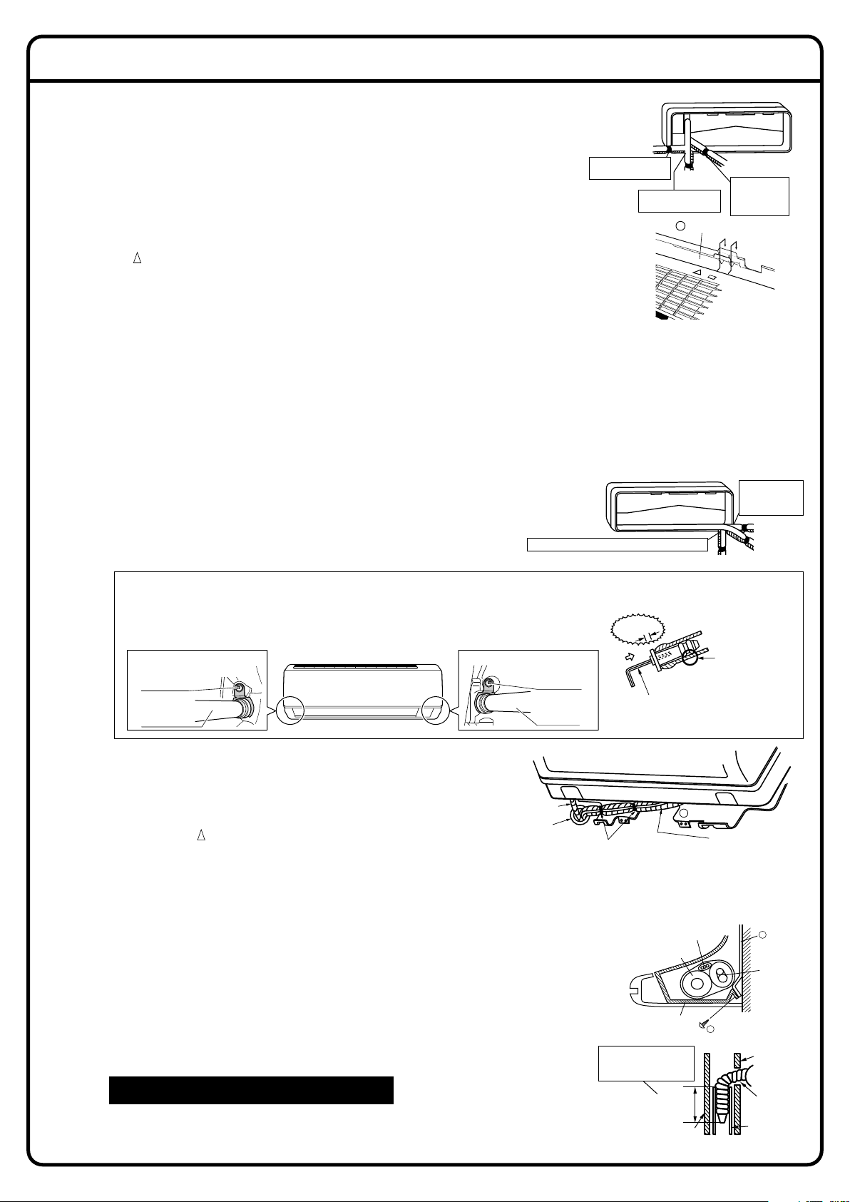
3-2. Left-side, left-back, or left-bottom piping.
1) Attach the drain hose to the underside of the refrigerant
pipes with adhesive vinyl tape.
2) Be sure to connect the drain hose to the drain port in
place of a drain plug.
3) Shape the refrigerant pipe along the pipe path marking
on the mounting plate.
4)
Pass drain hose and refrigerant pipes through the wall
hole, then set the indoor unit on mounting plate hooks,
using the markings at the top of indoor unit as a guide.
5) Pull in the inter-unit wire.
6) Connect the inter-unit pipes.
7) Wrap the refrigerant pipes and drain hose together with insulation tape
as right figure, in case of setting the drain hose through the back of the
indoor unit.
8) While exercising care so that the inter-unit wire do not catch indoor
unit, press the bottom edge of indoor unit with both hands until it is
firmly caught by the mounting plate hooks. Secure indoor unit to the
mounting plate with the screws (3/16” × 1/2”L (M4 × 12L)).
3. Installing indoor unit.
3-1. Right-side, right-back, or right-bottom piping.
1) Attach the drain hose to the underside of the refrigerant pipes
with an adhesive vinyl tape.
2)
Wrap the refrigerant pipes and drain hose together with an insulation tape.
3) Pass the drain hose and refrigerant pipes through the wall hole,
then set the indoor unit on the mounting plate hooks by using the
markings at the top of the indoor unit as a guide.
4)
Open the front panel, then open the service lid. (Refer to Installation Tips.)
5) Pass the inter-unit wire from the outdoor unit through the feed-
through wall hole and then through the back of the indoor unit.
Pull them through the front side. Bend the ends of tie wires
upward for easier work in advance. (If the inter-unit wire ends are
to be stripped first, bundle wire ends with adhesive tape.)
6) Press the bottom frame of the indoor unit with both hands to set it
on the mounting plate hooks. Make sure that the wires do not
catch on the edge of the indoor unit.
3-3. Wall embedded piping.
Follow the instructions given under
1) Insert the drain hose to this depth so it won’t be pulled out of
the drain pipe.
Left-side, left-back, or left-bottom piping .
Remove pipe port cover here for left-bottom piping.
Remove pipe port
cover here for
left-side piping.
Left-bottom piping
Left-side
piping
Left-back
piping
How to set the drain hose.
• Insert drain hose and tighten indoor unit fixing screw.
(Forgetting to attach this may cause water leakages.)
* The drain hose is on the back of the unit.
How to set the drain plug.
Front side of unit
Drain hose attachment position
Attachment on the left side
Drain hose
Indoor unit
fixing screw
Attachment on the right side (factory default)
Drain hose
Insulation
fixing screw
No gap
Do not apply
lubricating oil
(refrigerant oil)
when inserting.
Application of
causes deterioration
and drain leakage
of the plug.
Insert a hexagon wrench
(3/16 inch (4mm))
Wrap insulation tape
around the bent portion
of refrigerant pipe.
Overlap at least half the
width of the insulation
tape with each turn.
Drain
hose
Caulk this hole
with putty or
caulking material.
Bind with plastic
tape.
A
Mounting plate
Refrigerant
pipes
Drain hose
Bottom frame
H 3/16” × 1/2”L
(M4 × 12L) (3 point)
Inter-unit wire
Mounting
plate
A
Inner wall
Vinyl chloride
drain pipe
(VP-30)
Drain hose
1-15/16”
(50mm)
or more
Insert drain hose to this
depth so it won’t be
pulled out of drain pipe.
Outer wall
Right-bottom
piping
Right-back piping
Bind coolant pipe
and drain hose
together with
insulation tape.
Remove pipe port cover
here for right-side piping.
Remove pipe port cover
here for right-bottom piping.
Mounting plate
A
Loading ...
Loading ...
Loading ...