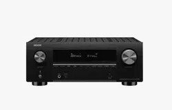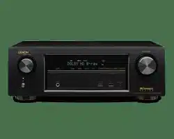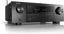
DENON
AV SURROUND RECEIVER
AV ,-5
Owner's Manual
Manuel de I'Utilisateur
[_ SAFETY PRECAUTIONS
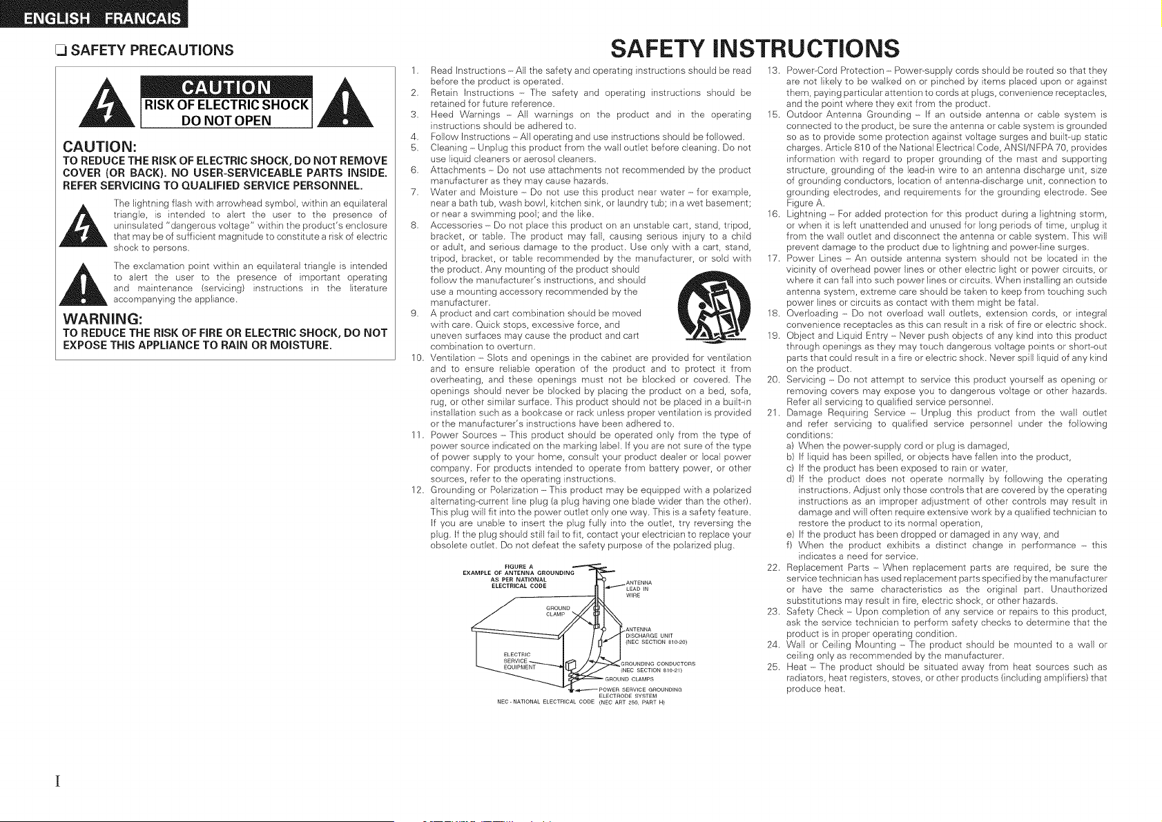
CAUTION:
TO REDUCE THE RiSK OF ELECTRIC SHOCK, DO NOT REMOVE
COVER (OR BACK). NO USER-SERVICEABLE PARTS iNSiDE.
REFER SERViCiNG TO QUALiFiED SERVICE PERSONNEL.
The lightning flash with arrowhead symbol, within an equilateral
_h triangle, is intended to alert the user to the presence of
uninsulated "dangerous voltage" within the product's enclosure
that may be of sufficient magnitude to constitute a risk of electric
shock to persons,
_j_ The exclamation point within an equilateral triangle }s intended
to alert the user to the presence of important operating
and maintenance (servicing) instructions in the literature
accompanying the appliance.
WARNING:
TO REDUCE THE RiSK OF FIRE OR ELECTRIC SHOCK, DO NOT
EXPOSE THIS APPLIANCE TO RAIN OR MOISTURE,
1.
2.
3.
4.
5.
6.
7.
10.
11.
12.
SAFETY INSTRUCTIONS
Read Instructions -All the safety and operating instructions should be read
before the product is operated.
Retain Instructions - The safety and operating instructions should be
retained for future reference.
Heed Warnings - All warnings on the product and in the operating
instructions should be adhered to.
Follow Instructions -All operating and use instructions should be followed.
Cleaning - Unplug this product from the wall outlet before cleaning. Do not
use liquid cleaners or aerosol cleaners.
Attachments - Do not use attachments not recommended by the product
manufacturer as they may cause hazards.
Water and Moisture ----Do not use this product near water - for example,
near a bath tub, wash bowl, kitchen sink, or laundry tub; in a wet basement;
or near a swimming pool; and the like.
Accessories ----Do not place this product on an unstable cart, stand, tripod,
bracket, or table. The product may fall, causing serious injury to a child
or adult, and serious damage to the product. Use only with a cart, stand,
tripod, bracket, or table recommended by the manufacturer, or sold with
the product. Any mounting of the product should
follow the manufacturer's instructions, and should
use a mounting accessory recommended by the
manufacturer.
A product and cart combination should be moved
with care. Quick stops, excessive force, and
uneven surfaces may cause the product and cart
combination to overturn.
Ventilation ----Slots and openings in the cabinet are provided for ventilation
and to ensure reliable operation of the product and to protect it from
overheating, and these openings must not be blocked or covered. The
openings should never be blocked by placing the product on a bed, sofa,
rug, or other similar surface. This product should not be placed }n a built-in
installation such as a bookcase or rack unless proper ventilation }s provided
or the manufacturer's instructions have been adhered to.
Power Sources ----This product should be operated only from the type of
power source indicated on the marking label. If you are not sure of the type
of power supply to your home, consult your product dealer or local power
company. For products intended to operate from battery power, or other
sources, refer to the operating instructions.
Grounding or Polarization -This product may be equipped with a polarized
alternating--current line plug (a plug having one blade wider than the other).
This plug will fit into the power outlet only one way. This is a safety feature.
If you are unable to insert the plug fully into the outlet, try reversing the
plug. If the plug should still fail to fit, contact your electrician to replace your
obsolete outlet. Do not defeat the safety purpose of the polarized plug.
ELECTRODE SYSTEM
NEC-NATIONAL ELECTRICAL CODE (NEC ART 250, PART H)
13. Power--Cord Protection - Power-supply cords should be routed so that they
are not likely to be walked on or pinched by items placed upon or against
them, paying particular attention to cords at plugs, convenience receptacles,
and the point where they exit from the product.
15. Outdoor Antenna Grounding ----If an outside antenna or cable system is
connected to the product, be sure the antenna or cable system is grounded
so as to provide some protection against voltage surges and built-up static
charges. Article 810 of the National Electrical Code, ANSI/NFPA 70, provides
information with regard to proper grounding of the mast and supporting
structure, grounding of the lead--in wire to an antenna discharge unit, size
of grounding conductors, location of antenna--discharge unit, connection to
grounding electrodes, and requirements for the grounding electrode. See
Figure A.
16. Lightning - For added protection for this product during a lightning storm,
or when it is left unattended and unused for long periods of time, unplug it
from the wall outlet and disconnect the antenna or cable system. This will
prevent damage to the product due to lightning and power-line surges.
17. Power Lines - An outside antenna system should not be located in the
vicinity of overhead power lines or other electric light or power circuits, or
where it can fall into such power lines or circuits. When installing an outside
antenna system, extreme care should be taken to keep from touching such
power lines or circuits as contact with them might be fatal.
18. Overloading - Do not overload wall outlets, extension cords, or integral
convenience receptacles as this can result in a risk of fire or electric shock.
19. Object and Liquid Entry ----Never push objects of any kind into this product
through openings as they may touch dangerous voltage points or short-out
parts that could result in a fire or electric shock. Never spill liquid of any kind
on the product.
20. Servicing - Do not attempt to service this product yourself as opening or
removing covers may expose you to dangerous voltage or other hazards.
Refer all servicing to qualified service personnel.
21. Damage Requiring Service - Unplug this product from the wall outlet
and refer servicing to qualified service personnel under the following
conditions:
a) When the power--supply cord or plug is damaged,
b) If liquid has been spilled, or objects have fallen into the product,
c) If the product has been exposed to rain or water,
d) If the product does not operate normally by following the operating
instructions. Adjust only those controls that are covered by the operating
instructions as an improper adjustment of other controls may result in
damage and will often require extensive work by a qualified technician to
restore the product to its normal operation,
e) If the product has been dropped or damaged in any way, and
f) When the product exhibits a distinct change in performance - this
indicates a need for service.
22. Replacement Parts ----When replacement parts are required, be sure the
service technician has used replacement parts specified bythe manufacturer
or have the same characteristics as the original part. Unauthorized
substitutions may result in fire, electric shock, or other hazards.
23. Safety Check ----Upon completion of any service or repairs to this product,
ask the service technician to perform safety checks to determine that the
product is in proper operating condition.
24. Wall or Ceiling Mounting - The product should be mounted to a wall or
ceiling only as recommended by the manufacturer.
25. Heat ----The product should be situated away from heat sources such as
radiators, heat registers, stoves, or other products (including amplifiers) that
produce heat.
FCC iNFORMATiON (For US customers}
1. PRODUCT
This product complies with Part 15 of the F:CC Rules. Operation is subject to the following two conditions: (1) this
product may not cause harmful interference, and (2) this product must accept any interference received, including
interference that may cause undesired operation.
2. IMPORTANT NOTICE: DO NOT MODIFY THIS PRODUCT
This product, when installed as indicated in the instructions contained in this manual, meets F:CC requirements.
Modification not expressly approved by DENON may void your authority, granted by the FCC, to use the product.
3. NOTE
This product has been tested and found to comply with the limits for a Class B digital device, pursuant to Part 15
of the FCC Rules. These limits are designed to provide reasonable protection against harmful interference in a
residential installation.
This product generates, uses and can radiate radio frequency energy and, if not installed and used in accordance
with the instructions, may cause harmful interference to radio communications. However, there is no guarantee
that interference will not occur in a particular installation. If this product does cause harmful interference to radio or
television reception, which can be determined by turning the product OFF and ON, the user is encouraged to try to
correct the interference by one or more of the following measures:
o Reorient or relocate the receiving antenna.
o Increase the separation between the equipment and receiver.
o Connect the product into an outlet on a circuit different from that to which the receiver is connected.
o Consult the local retailer authorized to distribute this type of product or an experienced radiof[V technician for
help.
This CJass B digital apparatus complies with Canadian ICES--O03.
Cet appare}l numerique de la classe B est conforme _ la norme NMB--OO3 du Canada.
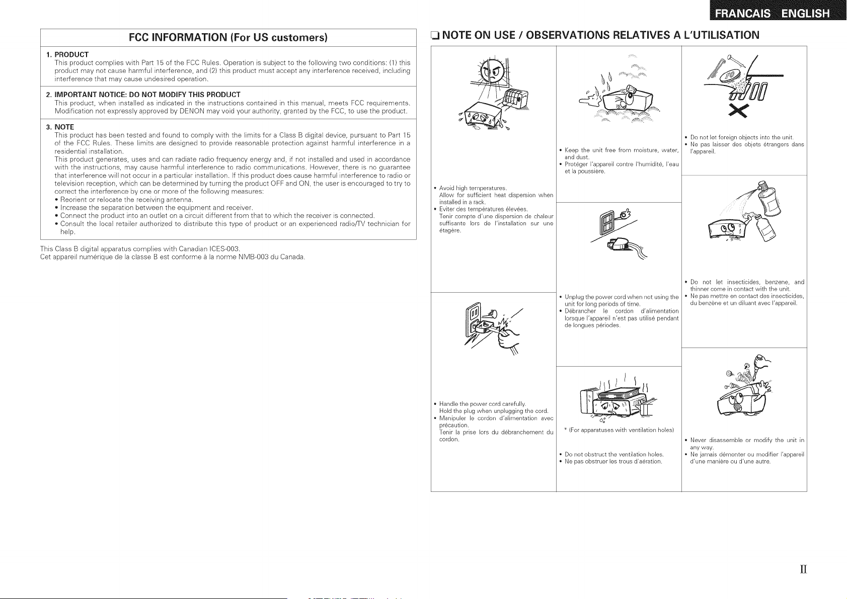
[_ NOTE ON USE / OBSERVATIONS RELATIVES A L'UTILISATION
• Avoid high temperatures.
Allow for sufficient heat dispersion when
installed in a rack.
• Eviter des temp6ratures 6levees.
Tenir compte d'une dispersion de chaleur
suffisante Iors de I'instalIation sur une
6tag6re.
Handle the power cord carefully.
Hold the plug when unplugging the cord.
• Manipuler le cordon d'aIimentation avec
precaution.
Tenir la prise Iors du dBbranchement du
cordon.
Keep the unit free from moisture, water,
and dust.
Prot6ger I'appareil contre I'humidite, I'eau
et la poussiere.
Unplug the power cord when not using the
unit for long periods of time.
D6brancher le cordon d'alimentation
Iorsque I'appareil n'est pas utiIis6 pendant
de Ionguesp6riodes.
_! ///
(For apparatuses with ventilation holes)
Do not obstruct the ventilation holes.
Ne pas obstruer les trous d'a6ration.
• Do not let foreign objects into the unit.
• Ne pas laisser des objets 6trangers dans
I'appareil.
Never disassemble or modify the unit in
any way.
Ne jamais demonter ou modifier I'appareil
d'une maniere ou d'une autre.
[J
Contents
Menu Map ................................................................................... 16 1_ Standard Playback ................................................ 27
Exam pies of Front Display ........................................................... 16 Surround Plavback of 2-channel Sources .................................... 27
m
Accessories ............................................... 2
Cautions on Handling ..................................................................... 3
Cautions on Installation ................................................................. 3
About the Remote Control Unit .................................................... 3
Insemng the Batteries ................................................................... 3
Operating Ra qge of the Remote Contro Unit ................................ 3
Part Names and Functions ............................................................ 4
Front Pane ................................................................................. 4
DisDlav .......................................................................................... 4
=
Preparations .................................................................................. 17
Auto Setup .................................................................................. 18
[] Auto Setup .............................................................................. 18
Playing Multi-channe Sources Do by Digital, DTS, etc.) ............. 27
DSP Simulation Playback ....................................................... 28
Direct Playback ....................................................................... 28
_ Stereo Playback ....................................................................... 28
[] -rror Messages ...................................................................... 19 -
Rear Pane ...................................................................................... 5
Remote Control Unit ...................................................................... 6
System Setup Operation ........................................................... 20
Exam pie of Display of Default Vagues ........................................ 20
1. Speaker Setup .......................................................................... 21
[]_ [] Speaker Configuration ..................................................... 21
[] Subwoofer Mode Setu_ ........................................................ 21
Jr_ m Dstance ..................................................................... 22
m _-[] Crossover Frequency ...................................................... 22
[] Test Tone ................................................................................ 22
[] Restore .................................................................................. 23
2. input Setup ............................................................................... 23
[],[] HDMI nAssig .............................................................. 23
lq-. [] Digital In Assign ........................................................ 24
[] iPod Asslg- -............................................................................ 24
[] Audio Delay. ............................................................................ 24
[] EXT. IN Subwoofer Leve ........................................................ 24
[] Auto Preset Memorv .............................................................. 24
m Parema LOCK........................................................................... 25
m Edit _OCKCode ........................................................................ 25
3. Option Setup ............................................................................. 26
[]-- [] Volume Comro ............................................................... 26
[] Auto SurreJnd Mode ............................................................. 26
I!_ Direct Mode SetuE................................................................... 26
[] Remote D Setup .................................................................... 26
Preparations .................................................................................... 7
Cables Used for Conr ectlons ...................................................... 7
Speaker Connections ..................................................................... 8
Speaker Installatior ....................................................................... 8
SpeaKer Connect ons .............................................................. 9
Connecting Equipment with HDMI connectors ........................ I 0
Connecting the Monitor .............................................................. ' "
Connecting the Playback Components ..................................... " "
DVD Raver .......................................................................... 11
CD Plaver .................................................................................. 12
Pod@.......................................................................................... 12
TV rCABLE Tuner .......................................................................... 12
Connecting the Recording Components ................................... 1
Video Cassette Recorder ......................................................... 13
CD Rec_raer/MD Recorder !Tape Deck .................................... 13
Connections to Other Devices ..................................... 13
Video Camera /Game Console .................................................... 13
Coroonem wttn Multi-channel Output connecTors .................... 14
SIRIUS connector ............................................................. 14
Antenn_ terminals ..................................................................... 15
Connecting the Power Cord ....................................................... I5
Once Connections are Completed ............................................. 15
Adjusting the parameters ............................................................ 29
Surround Parameter ................................................................. 29
[] Moae ................................................................................... 30
[] Cinema EQ ............................................................................ 30
[] D.ComD (Dynamic Range Compression) ................................ 30
[] LFE ........................................................................................ 30
[] Center image ......................................................................... 30
I_ Panorama .......................................................................... 30
[] Dirr_nsion ............................................................................. 30
D Center Width ........................................................................ 30
[] Delav Time ..................................................................... 30
[] Effect Level ........................................................................... 30
m Room Size ............................................................................... 30
[] SA/ATT (3ubwoofer Attenuation ........................................... 3"
[] Subwoofe ............................................................................. 31
[] Tone Contro .......................................................................... 31
[] Bass ........................................................................................ 31
[] Treble ........................................................................ 31
[] MultEQ .................................................................................... 31
[] Dvnamic EQ ........................................................................... 31
[] Dynamic Volume ................................................................... 32
[] DV Setting (Dynamic Volume Setting) .................................... 32
[] RESTORER ............................................................................. 32
[] Night Mode ............................................................................. 33
[] Default .................................................................................... 33
Preparations ............................................................................... 3=
-JrHng the Power On ................................................................ 33
Selecting the InDut Source ............................ 34
Setting tne InDuI Mode ............................................................... 34
Operations Durirg Playback ......................................................... 35
Playing Video and Audio Equipment ......................................... 35
Basic Operation ......................................................................... 35
Listening to FM/AIVI Broadcasts ................................................ 36
Basic Operation ............................................................................ 36
Presetting Radio Staticns (Preset Memorvl ................................ 36
Li_tenlrg to Preset Stations ........................................................ 36
Listening to SiRiUS Satellite Radio Programs .......................... 37
Basic Oaeradon .......................................................................... 37
Checking me SiRiUS Signal Strength and Radio ID .................... 37
Searching Categories .................................................................. 38
Parental Lock ................................................................................ 38
iPod ® Playback ............................................................................. 38
Preparations ........................................................ 3_
Li_te-- g to Audio ..................................................................... 33
/iewing Still Pictures or Videos on the iPod .............................. 39
Other Operations....;i:, v ..... :::.,:.:..;i....;. ,::..... ::,.:.:;::.,.-i::_::;.:.:.::.=O
Reqording On an External Device (REC OUT mode)!i-:: :;.:::-:i. i=0
Convenient Functions ::::::::::::::::::::::::: ========================================
Channel Level .:.:...:..::.:::.;...Lib::::. :.:,L:,:,IS::,L::I.:,::-::;:.:.:.:;_I..I_:40
Quick Select Function ..:;..:.;..ii:.:;;.i;;-:. :.:.i;,::::: :::::, .:..:-i:i.,:;.,41
Personal Memory Plus Function .I::.I::.:L:..-:;.L;?.:::.- .:::.i.;.:.::.:::41
East Function Memory .:L:,:L::.L: i.:.:: i:.££!. :k::.;i:.;,k:i.;,.:.::..::.;:41
Backup Memory.:.::.:::.::::.:..;:,:..:::.::..:: .;.:.;,:i : .:. ::: ;.: :.:.::..; 41
Resetting the Microprocessor ..................................................... 41
Operating DENON Audio
Presetting:::: :,:i: :::. :i:i ..:::,:i,il.i.;:.;i :i;:i;::,.i;:i-:i:.:ii:i;:i-:i:.::ik;42
Operating Preset Components:,L,£:,:-;:.,£:,:-4:;:.,£:,:-4:;:.,£:,:,42
Punch Through Function ===============================================================
Thank you for purchasing this DENON product. To ensure proper
operation, please read this owner's manual carefully before using the
product.
After reading them, be sure to keep them for future reference.
Check that the following parts are supplied with the product.
D
©
o
_:_
_ Owner's manual ...................................................................... 1
_ Getting Started ........................................................................ 1
Warranty (for North America model only) ................................ 1
Service station list ................................................................... 1
(5_ Remote control (RC-1104) ........................................................ 1
6_ R6/AA batteries ....................................................................... 2
(7-} FM indoor antenna .................................................................. 1
AM loop antenna ..................................................................... 1
(9_ Setup microphone
(DM-A409, Cord length: Approx. 25 ft / 7.6 m) ....................... 1
® ®
® ®
S
Z
©
©
S
©
2
B
0
o
o
u,
2
©
2
F' i
o
* Before turning the power switch on
Check once again that all connections are correct and that there are
no problems with the connection cables.
* Power is supplied to some of the circuitry even when the unit is
set to the standby mode. When traveling or leaving home for long
periods of time, be sure to unplug the power cord from the power
outlet.
* About condensation
If there is a major difference in temperature between the inside of
the unit and the surroundings, condensation (dew) may form on
the operating parts inside the unit, causing the unit net to operate
properly.
If this happens, let the unit sit for an hour or two with the power
turned off and wait until there is little difference in temperature
before using the unit.
* Cautions on using mobile phones
Using a mobile phone near this unit may result in noise. If so, move
the mobile phone away from this unit when it is in use.
* Moving the unit
Turn off the power and unplug the power cord from the power
outlet.
Next, disconnect the connection cables to other system units before
moving the unit.
* Note that the illustrations in these instructions may differ from the
actual unit for explanation purposes.
..................................Note:
Uz:_
11;
For proper heat dispersal, do not install this unit in a confined
space, such as a bookcase or similar enclosure.
"//////////////////////////////////////////////////
•_ Note
X////////////////////////////////////////////////×
In addition to the AVR-589, the included remote control unit (RC-1104)
can also be used to operate the equipment listed below.
@} DENON system components
Non-DENON system components
o By setting the preset memory (L_page 42 ~ 44)
@_ Lift the clasp and remove the rear lid. _,_
Load the two batteries properly as indicated f_,.._¢_.'---.._
by the marks in the battery compartment, f_o'o_ _"'_
m6/AA '__'_
@ Put the rear cover back on.
* Replace the batteries with new ones if the set does not operate
even when the remote control unit is operated close to the unit.
* The supplied batteries are only for verifying operation.
* When inserting the batteries, be sure to do so in the proper direction,
following the "0" and "@" marks in the battery compartment.
o To prevent damage or leakage of battery fluid:
o Do not use a new battery together with an old one.
o Do not use two different types of batteries.
o Do net attempt to charge dry batteries.
o Do not short-circuit, disassemble, heat or dispose of batteries in
flames.
o If the battery fluid should leak, carefully wipe the fluid off the inside
of the battery compartment and insert new batteries.
o Remove the batteries from the remote control unit if it will not be in
use for long periods.
oWhen replacing the batteries, have the new batteries ready and
insert them as quickly as possible.
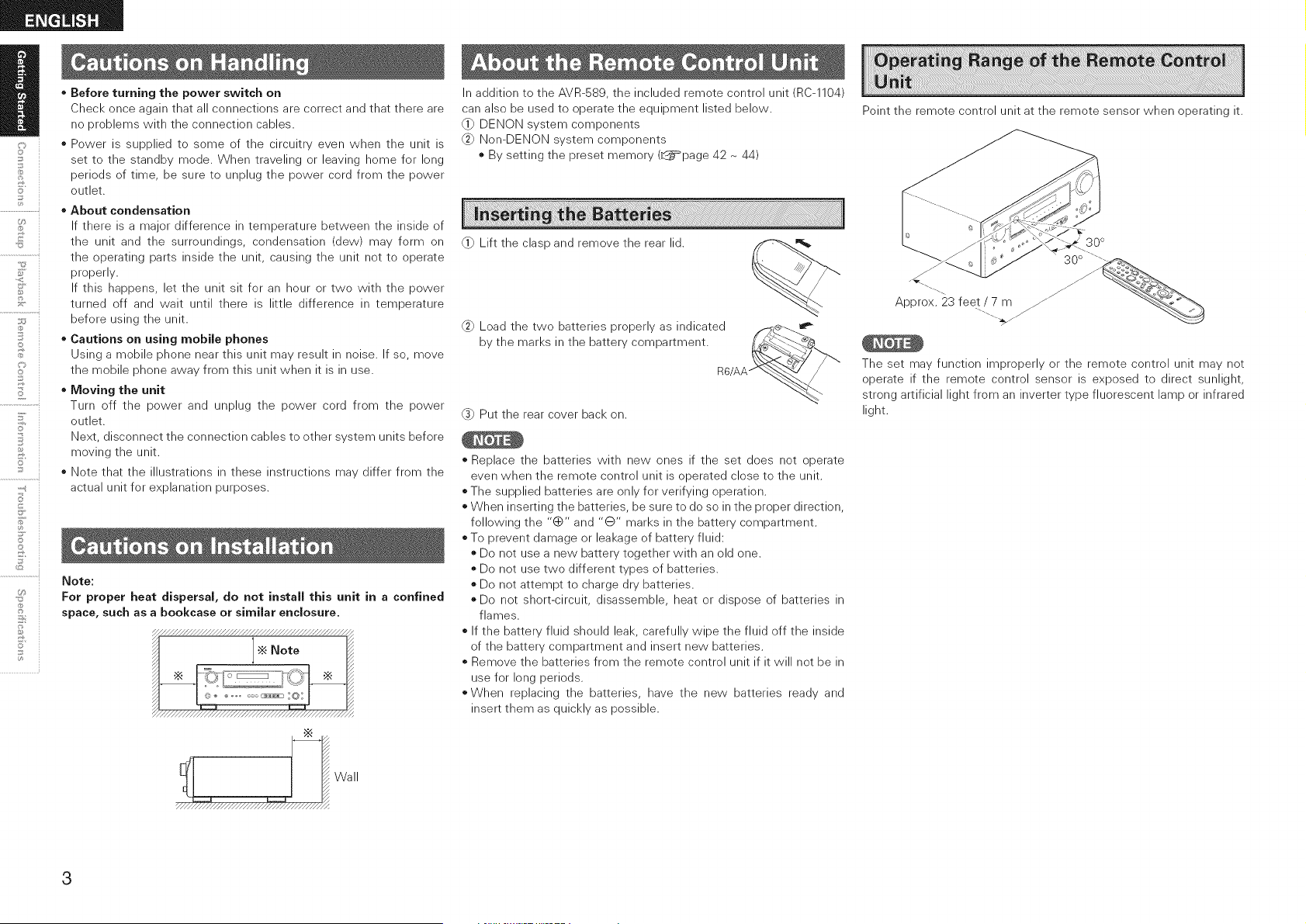
Point the remote control unit at the remote sensor when operating it.
30 °
-..
Approx. 23 feet / 7 m
'-....
The set may function _mproperly or the remote control unit may net
operate if the remote control sensor is exposed to direct sunlight,
strong artificial light from an inverter type fluorescent lamp or infrared
light.
Wall
3

For buttons not explained here, see the page indicated in parentheses ().
.................:
...............1 I-H T,,,'<I
kk -
O Power operation button
(ON/STANDBY) .......................................... (34)
Power indicator .......................................... (34)
O Power switch (_ON mOFF} ............... (34, 41 )
O Headphone jack (PHONES) ........................ (35)
O INPUT MODE button .................................. (34)
OSPEAKERS buttons .............................. (35, 41)
QUICK SELECT buttons ............................. (41)
V. AUX INPUT connectors
Remove the cap covering the connectors when
you want to use them.
lL II
© O ....... "
o o o 0 0 ......... j_., ,,_#, +
SETUP MIC jack .......................................... (17)
_) SYSTEM SETUP button ............................. (20)
SURF{. MODE / SURF{. PARA button ..... (27, 29)
_SELECT/ENTER knob
*The SELECT/ENTER knob on the main unit
operates in the same way as the cursor <] and D
buttons on the remote control unit.
SELECT / ENTER
*The control functions in the same way as the
cursor <] button when turned counterclockwise,
as the cursor D button when turned clockwise.
©The control functions in the same way as the
ENTER button when pressed the knob.
_)Cursor buttons (AV) ................................. (20)
_) MASTER VOLUME control knob ............... (35)
_) Dynamic Volume indicator ........................ (32)
MultEQ indicator ........................................ (31)
Master volume indicator
_}) INPUT mode indicators .............................. (34)
_) SIGNAL indicators
_) Display
SPEAKERS indicators ................................. (35)
Remote control sensor ................................ (3)
_) REC SELECT button ................................... (40)
_) SOURCE SELECT knob .............................. (34)
_) SOURCE button .......................................... (34)
_!) STATUS button .......................................... (33)
DIMMER button .......................................... (35)
_) RESTORER button ...................................... (32)
_) BAND button .............................................. (36)
SHIFT button ............................................... (36)
PRESET CHANNEL buttons (AT) .............. (36)
_) TUNING buttons (AT) ................................ (36)
_) MULTEQ button ......................................... (31)
_D DYNAMIC VOLUME button ....................... (32)
•_ About Dynamic Volume
Audyssey Dynamic Volume TM solves the problem
of large variations in volume level between
television programs, commercials, and between
the soft and loud passages of movies.
Audyssey Dynamic EQTM is integrated into
Dynamic Volume so that as the playback volume
is adjusted automatically, the perceived bass
response, tonal balance, surround impression,
and dialog clarity remain the same.
•_ About Dynamic EQ
Audyssey Dynamic EQ solves the problem of
/
©
o
_:_
deteriorating sound qualityas volume is decreased .................................
by taking into account human perception and i
room acoustics. Audyssey Dynamic EQ works in _i
tandem with Audyssey MultEQ @to provide well- _6
balanced sound for every listener at any volume ...................................
level, ii _
@VIDEO SELECT button ............................... (35)
©
_]_ Signal channel indicator
Lights when the preset channel is displayed at
O.
Information display
Input signal indicators
Master volume indicator
This displays the volume level.
The Setup item number is displayed in System
Setup.
Recording output source indicator
This lights when the REC OUT mode is
selected. (This indicator is off when "SOURCE"
is selected.)
_Tuner reception mode indicators
These light according to the reception conditions
when the input source is set to "TUNER".
* AUTO
This lights when in the auto tuning mode.
* STEREO
In the FM mode, this lights when receiving
analog stereo broadcasts.
* TUNED
This lights when the broadcast is properly tuned
in.
©
©
©
4
B
©
©
©
2
7
©
5'
©
)CK CONTROL _,_ SIRIUS l
8m
CD-R/ VCR DVD/ TV/ VCR CD-R/
TAPE HOP CBL flPod) TAPE
CO SW SR
SPEAKER IMPEDANCE
FRONTAORS: _1_£_ RENTER :6_16£z
A + £ :12_16£_ SURROUND : 6_16_
l
AC OUTLETS
AC120V
60Hz
SWITCHEDTOTAL120W(1_) MAX.
©
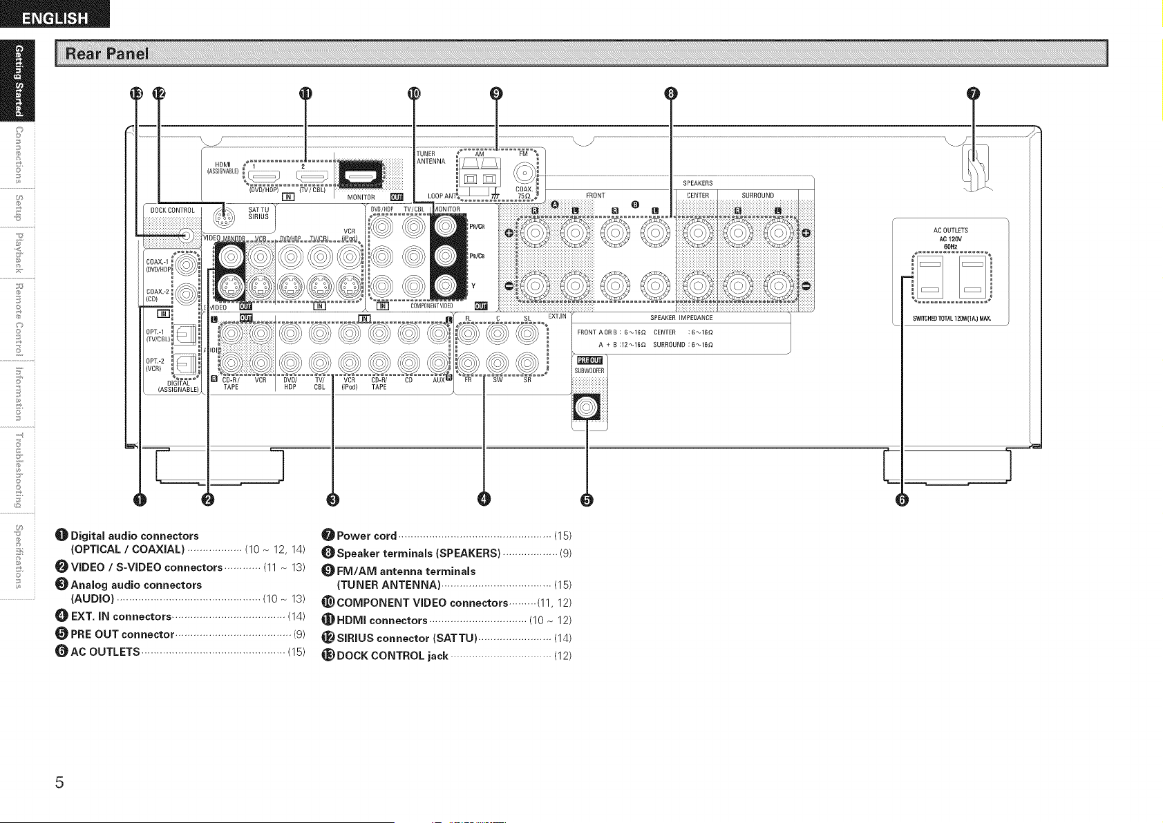
_]_ Digital audio connectors
(OPTICAL / COAXIAL) .................. (10 ~ 12, 14)
_VIDEO / S-VIDEO connectors ............ (11 ~ 13)
_Analog audio connectors
(AUDIO) ............................................... (10 ~ 13)
EXT, iN connectors ..................................... (14)
PRE OUT connector ...................................... (g)
_AC OUTLETS ............................................... (15)
_ Power cord .................................................. (15)
_Speaker terminals (SPEAKERS) .................. (g)
FM/AM antenna terminals
(TUNER ANTENNA) .................................... (15)
_COMPONENT WDEO connectors ......... (11, 12)
_HDMI connectors ................................ (10 ~ 12)
_SIRIUS connector (SATTU) ........................ (14)
_) DOCK CONTROL jack ................................. (12)
5
[ Front ]
_Po_/ NEn_0RK1 rXUN_
AUDIO --CD--
.................................?
DENON
®
-.@
-@
--@
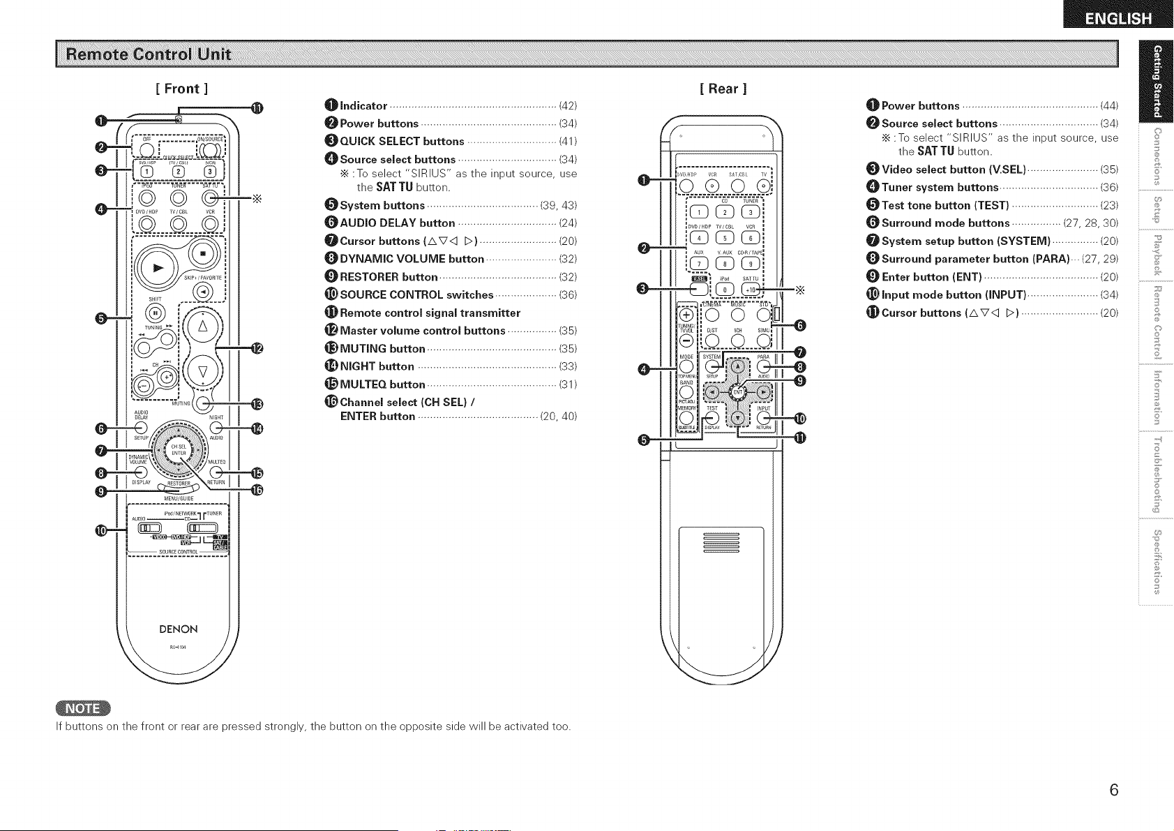
Indicator ...................................................... (42)
Power buttons ............................................ (34)
_QUICK SELECT buttons ............................. (41)
_]_Source select buttons ................................ (34)
•_ :To select "SIRIUS" as the input source, use
the SAT TU button.
_System buttons .................................... (39, 43)
_AUDIO DELAY button ................................ (24)
_Cursor buttons (AV< D) ......................... (20)
DYNAMIC VOLUME button ....................... (32)
RESTORER button ...................................... (32)
_}SOURCE CONTROL switches .................... (36)
Remote control signal transmitter
Master volume control buttons ................ (35)
_) MUTING button .......................................... (35)
_) NIGHT button ............................................. (33)
_) MULTEQ button .......................................... (31)
@Channel select (CH SEL) /
ENTER button ....................................... (20, 40)
If buttons on the front or rear are pressed strongly, the button on the opposite side will be activated too.
[ Rear ]
,., _ DVB/4DP YC£ SA{ ZJBL IV
/ io coGE
_DVD/HDP TV/CB VCR
AUX VAUX C04_/TAPE_
i _ I lI_1_llm) iPod SATTU I
II1 ]o o oil _
VVOL _ D/ST 5CH SIMU=
111
#0DE "YST_ _ PARA
_l_ ....................
O
',%1
_t Power buttons ............................................ (44)
_Source select buttons ................................ (34)
•_ :To select "SIRIUS" as the input source, use
the SAT TU button.
_Video select button (V.SEL) ....................... (35)
_Tuner system buttons ................................ (36)
_Test tone button (TEST) ............................ (23)
_Surround mode buttons ................ (27, 28, 30)
_System setup button (SYSTEM} ............... (20)
_Surround parameter button (PARA)... (27, 29)
Enter button (ENT) ..................................... (20)
_} Input mode button (INPUT) ....................... (34)
_Cursor buttons (AV<] D) ......................... (20)
D
©
©
Z
©
©
©
Jo
6
s i
.............. i
2
s_
©
2
7
@
5'
7
©
@
U_
Connections for all compatible audio and video signal formats
are described in this owner's manual. Please select the types of
connections suited for the equipment you are connecting.
With some types of connections, certain settings must be made
on the AVRi589. For details, refer to the instructions for the
respective connection items below.
* Do not plug in the power cord until all connections have been
completed.
o When making connections, also refer to the operating instructions of
the other components.
o Be sure to connect the left and right channels properly (left with left,
right with right).
o Do not bundle power cords together with connection cables. Doing
so can result in humming or noise.
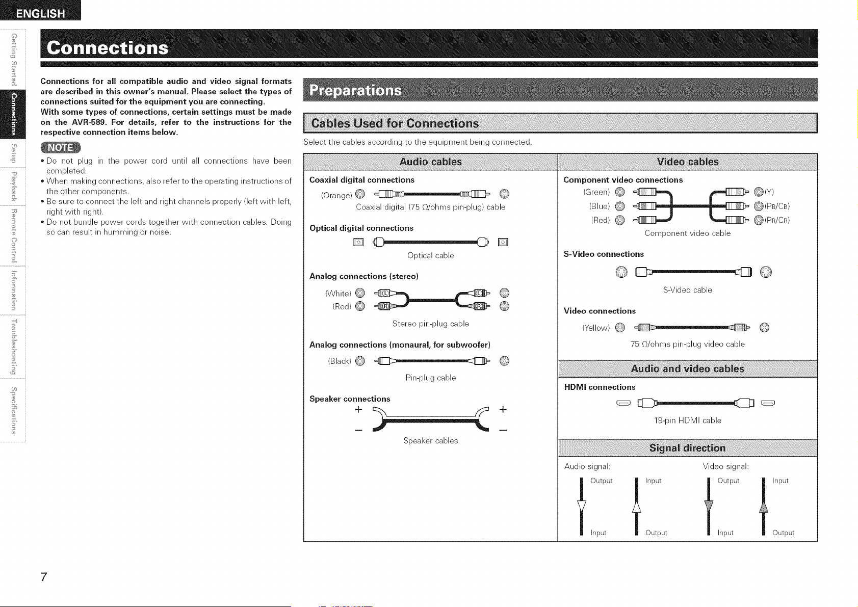
Select the cables according to the equipment being connected.
; ; ; ; ; ; ; ; ; ; ; ; ; ; ; ; ;
Coaxial digital connections
(Orange) (_ i , I
Coaxial digital (75 @/ohms pin-plug) cable
Optical digital connections
[]
Optical cable
Analog connections {stereo}
(White)
(Red) (_
Stereo pin-plug cable
[]
Analog connections (monaural, for subwoofer)
(Black) (_
Pin-plug cable
Speaker connections
Speaker cables
__i(i!!i!iii!i!ii_ii{{!ii_iiiii{!ii_iiiiii!iii_ili_iii_ii!'!!i!i!i!i!i;!;i_iillill_ii!iiii_i_i!ii!ii_i;!{_!i_iiiii{ii!i_i_,i!i_iiliiii_!iiiii!iiii_i_i!ii!ii_i;!ii!_!i_iiiiiiiiii_i_i!ii!ii_i;!ii!i_}_i}i!_iI!i!i!_iliiii_ii{i_i!_!i_ii_iiii_ii{i_i!_!i_i!;i_iii!!ii_ii!_i_!i!_i_!iiiiiiiiiiiii!!i!13iii!ii!i_i_iii_:_!!i!_i{_il}!_:_Siii_i_i!ii!ii_i;!{_!i_iiiiiiiiii_i_i!ii!ii_i;!{_!i_iiiiiiiiii_i_i!ii!ii_i;!{_!i_iiiiiill!iiii_i_i!ii!ii_i;!{_!i_ii{i!iiii_i_i!ii!ii_i;!{_!i_ii{i!iiii_i_i!ii!ii_i;!{_!i_ii{i!iiii_i_i!ii!ii_i;!{_!i_ii{i!iiii_i_i!ii!ii_i;!{_!i_ii{i!iiii_i_i!ii!ii_i;!{_!i_ii{i!iiii_;i_ii{il;;i_!__i_iiiiiii!iiii_;i_ii{il;;i_!__i_iiiiiii!iiii_;i_ii{il;;i_!__i_iiiiiii!iiii_;i_ii{il;;i_!__i_iiiii
Component video connections
(Green) _ _ _(Y)
(Blue) @ _ _(PB/CB)
(Red) @ _(PR/CR)
Component video cable
S-Video connections
S-Video cable
Video connections
(Yellow) @
75 @/ohms pin-plug video cable
HDMI connections
19-pin HDMI cable
Audio signal: Video signal:
loutputl'nputtoutput
Input Output Input
t Input
Output
7
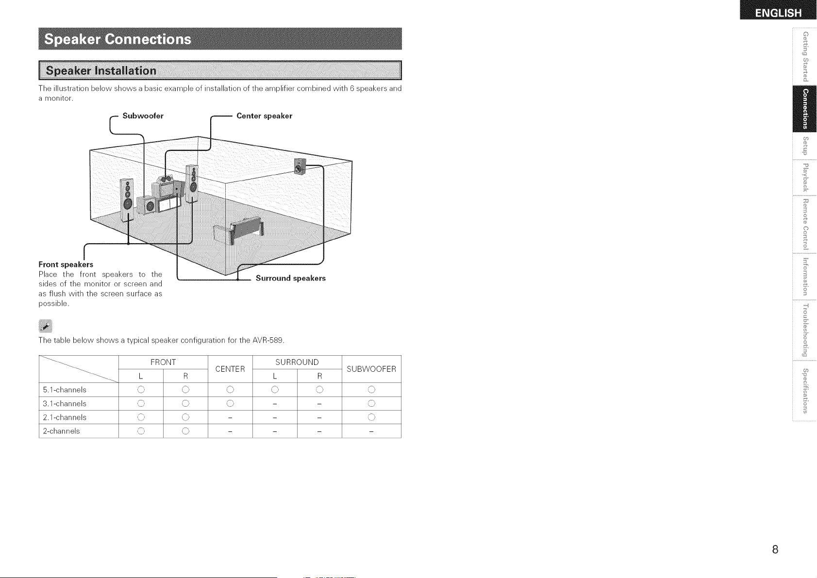
The illustration below shows a basic example of installation of the amplifier combined with 6 speakers and
a monitor.
£
U
£
r
Front speakers
Place the front speakers to the
sides of the monitor or screen and
as flush with the screen surface as
possible.
The table below shows a typical speaker configuration for the AVR-589.
5.1-channels
3.1-channels
2.1-channels
2-channels
FRONT
SUBWOOFERCENTER
\J
\J
SURROUND
L R
\J \J
L R
,{}, ,C';, ,C},
,{}, ,C';, ,C},
,{}, ,C';, ,C},
,_}, ,C';,
S
Z
©
©
S
©
8
©
2
7
o
5'
©
if
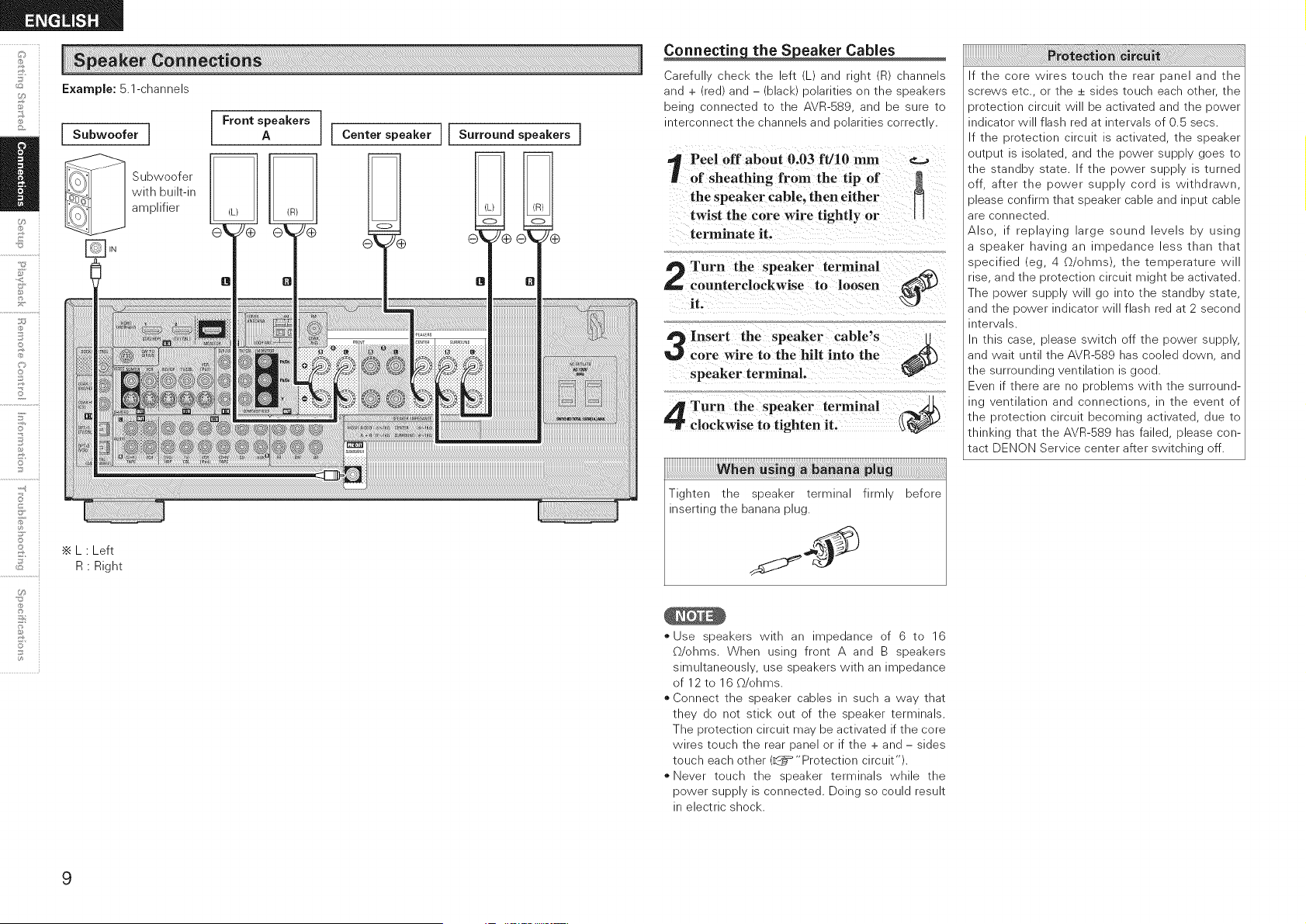
U_
Example: 5.1-channels
I Subwoofer I
Subwoefer
with built-in
amplifier
•_ L • Left
R Right
I Front speakers
A I Center speaker II
9
Surround speakers !
Carefu cnec_ _ne eft _ ana rlgm _D channels
ana - real an(3 -- DlaCI _ oolarltles on ;ne sloeaKers
being cennectea ;e ;ne AVR-S89 ana De sure to
merconnect tne cnannels and ioolarltles correc_ .,
Peel off about 0.03 ft/10 mm _._
of sheathing from the tip of
the speaker cable, then either N
twist the core wire tightly or
terminate it.
Turn the speaker terminal _x
counterclockwise to loosen _)M
Insert the speaker cable's
core wire to the hilt into the
speaker terminal.
Turn the speaker terminal
clockwise to tighten it.
When using a banana plug
Tigmen ;ne 3beaKer termlna _;_
inseRing me Danana plug.
before
" Jse sloeaKers NlIn an _oeaance of 6 _o 16
enms When uslnc front _ ana B speakers
slmul;aneous Jse sloeaKers NIIn at _Deqance
of 12 to 16 _/ehms.
o Connect the speaker cables in such a way that
they do not stick out of the speaker terminals.
The protection circuit may be activated if the core
wires touch the rear panel or if the + and - sides
touch each other (_ "Protection circuit").
oNever touch the speaker terminals while the
power supply is connected. Doing so could result
in electric shock.
If the core wires touch the rear panel and the
screws etc., or the + sides touch each other, the
)retection circuit will be activated and the power
indicator will flash red at intervals of 0.5 secs.
If the protection circuit is activated, the speaker
output is isolated, and the power supply goes to
the standby state. If the power supply is turned
off, after the power supply cord is withdrawn,
)lease confirm that speaker cable and input cable
are connected.
Also, if replaying large sound levels by using
a speaker having an impedance less than that
specified (eg, 4 _/ohms), the temperature will
rise, and the protection circuit might be activated.
The power supply will go into the standby state,
and the power indicator will flash red at 2 second
intervals.
In this case, please switch off the power supply,
and wait until the AVR-589 has cooled down, and
the surrounding ventilation is good.
Even if there are no problems with the surround-
ing ventilation and connections, in the event of
the protection circuit becoming activated, due to
thinking that the AVR-589 has failed, please con-
tact DENON Service center after switching off.
r DVD player
I AUDIO
i HDMI
OUT
J
Monitor
HDMI
IN
When HDMI input signals are sent to the
monitor as HDMI output, both video and
audio are output to the monitor.
_signal input to the HDIVll
I input connector cannot be played
I ontheAVR- 89Inputtheaudiosignal
I to the digital audio input connector or
I analog audio input connector.
•_ The AVR-589 is equipped for HDMI version 1.3a. This version is compatible with other versions, allowing
connection to all components equipped with an HDMI connector.
•_ The AVR-589 is compatible with 30- and 36-bit Deep Color.
•_ The AVR-589 can be connected to a device equipped with an HDMI output connector using an HDMI
cable.
•_ The AVR-589 is compatible with HDMI Ver. 1.3a Deep Color and xvYCC.
o The AVR-589 cannot be controlled from another device via the HDMI cable.
o Video signals are not output if the input video signals do not match the monitor's resolution. In this case,
switch the DVD player's resolution to a resolution with which the monitor is compatible.
o Use a cable on which the HDMI logo is indicated (a certified HDMI product) for connection to the HDMI
connector. Normal playback may not be possible when using a cable other than one on which the HDMI
logo is indicated (a non-HDMI-certified product).
o If the monitor or DVD player does not support Deep Color, deep color signal transfer is not possible.
o If the monitor or DVD player does not support xvYCC, xvYCC signal transfer is not possible.
oThe audio and video signals input to the AVR-589's HDMI input connector are output unchanged from
the HDMI output connector. Because of this, the sound is output from the monitor connected using the
HDMI connectors, but in order to take full advantage of the AVR-589's playback sound, turn the TV's
volume down.
o If the connected monitor or DVD player only has a DVI-D connector, use an HDMI/DVI converter cable.
When using a DVI cable, no audio signals are transmitted.
o Use a Deep Color compatible cable for connection to Deep Color compatible devices.
o HDMI video signals are theoretically compatible with the DVI format.
When connecting to a monitor, etc., equipped with a DVI-D connector, connection is possible using an
HDMI/DVI converter cable, but depending on the combination of components in some cases the video
signals will not be output.
o When connecting using an HDMI/DVI converter adapter, the video signals may not be output properly
due to poor connections with the connected cable, etc.
£
U
£
S
Z
©
©
S
©
10
&
©
2
7
o
5'
7
©
U_
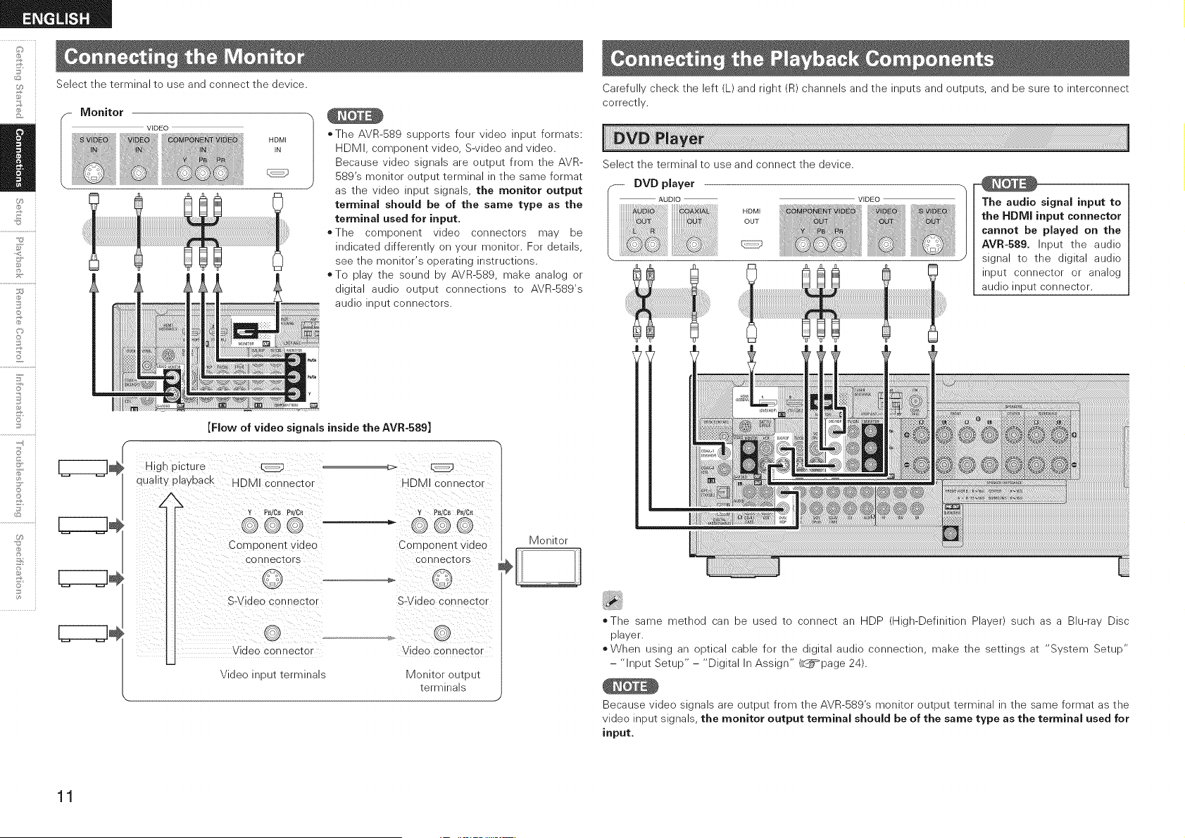
Select the terminal to use and connect the device.
CZZZZ3
CZZZZ3
VIDEO
HDMI
IN
*The AVR-589 supports four video input formats:
HDMI, component video, S-video and video.
Because video signals are output from the AVR-
589's monitor output terminal in the same format
as the video input signals, the monitor output
terminal should be of the same type as the
terminal used for input.
=The component video connectors may be
indicated differently on your monitor. For details,
see the monitor's operating instructions.
oTo play the sound by AVR-589, make analog or
digital audio output connections to AVR-589's
audio input connectors.
[Flow of video signals inside the AVR-589]
High picture
quality playback HDMI connector
HDMI connector
Y Ps/CB PPdCR Y PB/CB PR/CR
Component video
connectors
Component video
connectors
S-Video connector S-Video connector
Video connector
Video input terminals
Video connector
Monitor output
terminals
J
Monitor
Carefully check the left (L) and right (R) channels and the inputs and outputs, and be sure to interconnect
correctly.
Select the terminal to use and connect the device.
DVD player
AUDIO
i HDMI
OUT
The audio signal input to
the HDMI input connector
cannot be played on the
AVR-589. Input the audio
signal to the digital audio
input connector or analog
audio input connector.
The same method can be used to connect an HDP (High-Definition Player) such as a Blu-ray Disc
player.
o When using an optical cable for the digital audio connection, make the settings at "System Setup"
- "Input Setup" - "Digital In Assign" (_page 24).
Because video signals are output from the AVR-S89's monitor output terminal in the same format as the
video input signals, the monitor output terminal should be of the same type as the terminal used for
input,
11
Select the terminal to use and connect the device.
When using an optical cable for the digital audio connection, make
the settings at "System Setup" - "Input Setup" - "Digital In
Assign" (_page 24).
Use a DENON control dock for iPod (ASD-1 R, ASD-3N or ASD-3W
sold separately) to connect the iPod to the AVR-S89. For instructions
on the control dock for iPod settings, refer to the control dock for
iPod's operating instructions.
iPod
* With the default settings, the iPod can be used connected to the
VCR (iPod) connector.
*To assign the iPod to a connector other than VCR (iPod), make
the settings at "System Setup" - "Input Setup" - "iPod Assign"
(L_=page 24).
Video/S-Video or Component Video connections are required
to playback iPod Video or Photos on TV monitor,
Select the terminal to use and connect the device.
The audio signal input to the HDMI input connector cannot be
played on the AVR-589. Input the audio signal to the digital audio input
connector or analog audio input connector.
-- TV tuner
I AUDIO
i HDMI
OUT
VIDEO
When using a coaxial cable for the digital audio connection, make the settings
at "System Setup" - "Input Setup" - "Digital In Assign" (_page 24).
Because video signals are output from the AVR-S89's monitor output terminal
in the same format as the video input signals, the monitor output terminal
should be of the same type as the terminal used for input,
U
£
S
Z
i o
i o
S
©
12
Carefully check the left (L) and right (R) channels and the inputs and outputs, and be sure to interconnect correctly.
+,©
©
2
7
@
5'
©
@
U_
Select the terminal to use and connect the device.
VIDEO AUDIO
When recording via the AVR-589, the playback device's cable must
be of the same type as the cable used to connect the AVR-589's VCR
OUT connector.
Example: TV IN --> S-Video cable : VCR OUT --> S-Video cable
TV IN --> Video cable : VCR OUT --> Video cable
Select the terminal to use and connect the device.
CD recorder /
MD recorder /
Carefully check the left (L) and right (R) channels and the inputs and
outputs, and be sure to interconnect correctly.
Select the terminal to use and connect the device.
Video camera /
13
Select the terminal to use and connect the device.
oTo play the analog input signals input to the EXT. IN connectors,
press the iNPUT MODE button on the main unit or the JNP[J]" button
on the remote control unit and select "EXT. IN" (_page 34).
oThe video signal can be connected in the same way as a DVD player
(_page 11).
o To play copyright-protected discs, connect the AVR-SS9's EXT.
IN connector with the DVD player's analog multi-channel output
connector.
*The AVR-589 is a SIRIUS Satellite Radio Ready ® receiver. You can
receive SIRIUS ® Satellite Radio by connecting to the SiriusConnect
Home Tuner and subscribing to the SIRIUS service.
* Plug the SIRIUS connector on the rear panel.
* Position the Home Tuner antenna near a south-facing window to
receive the best signal.
For details, see "Listening to SIRIUS Satellite Radio Programs"
(L_=_page 37).
When making connections, also refer to the operating instructions of
the SiriusConnect Home Tuner.
SiriusConneet Home Tuner
l '_ When connecting
digital audio.
=a
When connecting the Optical terminal, set the input Optical terminal
allocations for "System Setup" - "Input Setup" - "Digital In Assign",
in "SIRIUS".
Keep the power cord unplugged until the SiriusConnect Home Tuner
connection have been completed.
@2006 SIRIUS Satellite Radio Inc. "SIRIUS", the SIRIUS dog logo,
and channel names and Iogos are trademarks of SIRIUS Satellite
Radio Inc.
U
£
[3 Positioning the Antenna _,
For a consistent satellite signal, the antenna must be positioned .............._
correctly. Use the following map to determine which area you are in ili
and position the antenna accordingly.
SKY
WEST EAST
SOUTH
HORIZON
Area 1 : Point the antenna toward the sky in the east, northeast, or
southeast, either through a window or outside.
Area 2 : Point the antenna toward the sky in the north or northeast,
either through a window or outside.
Area 3 : Point the antenna toward the sky in the north or northwest,
either through a window or outside.
Area 4 : Point the antenna toward the sky in the west, northwest, or
southwest, either through a window or outside.
Area 5 : Put the antenna outside and point it straight up.The antenna
cannot be used indoors.
S
Z
©
©
S
©
©
14
&
©
2
7
o
5' i
7
...............
U_
An F-type FM antenna cable plug can be connected directly.
AM loop antenna
(supplied)
Direction of broadcasting station
FM antenna'_ _
,I
75 O/ohms
Coaxial cable
FM indoor
antenna
(supplied)
7
AM outdoor antenna
Ground
Q AM loop antenna assembly
Remove the vinyl tie and take out
the connection line.
Bend in the reverse direction.
Mount
a. With the antenna on top of any
stable surface.
b. With the antenna attached to a
wall.
Installation hole Mount
on wall, etc,
1. Push the lever. 2. Insert the conductor. 3. Return the lever.
=:> =_>
Note to CATV system installer:
This reminder is provided to call the CATV system installer's
attention to Article 820-40 of the NEC which provides guidelines
for proper grounding and, in particular, specifies that the cable
ground shall be connected to the grounding system of the building,
as close to the point of cable entry as practical.
Wait until all connections have been completed before connecting the
power cord.
Power cord __
.................... To household
power outlet
[_] [_] (AC120V, 60Hz)
o These outlets supply power to external
audio equipment.
oThe power supplied from these outlets
turns on and off together with the set's
power switch.
o Audio equipment with a total power
consumption of 120 W (1 A) can be
connected.
o Insert the AC plugs securely. Incomplete connections could cause
noise.
o Only use the AC outlets to plug in audio equipment. Do not use
them as power supplies for hairdryers or anything other than audio
equipment.
15
Some typical examples are described below.
•_ When the setup microphone is connected.
FJStart Menu
Step 1: Speaker Detection
Step 2: Measurement
Step 3: Calculation
Step 4: Check
o Step 5: Store
Q Speaker Setup (_page 21 ~ 23)
Speaker Configuration
Subwoofer Mode Setup
Distance
Crossover Frequency
Test Tone
e Restore
rj input Setup (_page 23 ~ 25)
° HDMI In Assign
° Digital In Assign
= iPod Assign
• Audio Delay
• EXT. IN Subwoofer Level
• Auto Preset Memory
• Parental Lock
• Edit Lock Code
rj Option Setup (_page 26)
• Volume Control
. Volume Limit
. Power On Level
. Mute Level
° Auto Surround Mode
• Direct Mode Setup
• Remote ID Setup
rj Surround Parameter
, Mode • DelayTime • MultEQ
, Cinema EQ • Effect Level • Dynamic EQ
, D. Comp • Room Size • DynamicVolume
, LFE • SW ATT • DV Setting
, Center Image • Subwoofer • RESTORER
, Panorama • Tone Control • Night Mode
. Dimension • Bass • Default
, CenterWidtb • Treble
] H[}i:iZ] ::[}LJ[}
Item number
Currently selected line
Menu number
Current setting
Press the q button to select.
Currently selected line
:i.i::= 'i ,, 'i O i_ (ii: ___(ii::iii:Q_ "
_J
©
©
Z
S
jo
©
0
8
16
©
5'
©
Button located on both the main unit and the remote control
unit _ BU'N'ON
Button only on the main unit > <Bur[0N>
MASTER VOLUME /",V
Audyssey MultEQ automatically measures the acoustical problems
in the listening environment to create the best audio experience for
your home theater.
Audyssey MultEQ optimizes a large listening area where one or
more listeners are seated.
Measurements are performed by placing the calibrated microphone
(DM-A409) successively at multiple positions throughout the
listening area as shown in Example (i_. For best results, it is strongly
recommended to measure 6 positions so that the measurements
have the proper spatial weighting.
Even if the listening environment is small as shown in Example @,
measuring at multiple points throughout the listening environment
results in more effective correction.
E×ample _ E×ample
t Press <SPEAKERS> to select the front speakers Front
Jr A, Front B or Front A+B.
Connect the included calibrated setup microphone to
a_, the SETUP MIC jack on the main unit.
"A J_o Set<Start" is alsplayea.
_ceE Lot _ _._
[Front]
<SPEAKERS> SETUPMIC jack ENTER,<3
AV<3 -
i ]__!_I_
_i _, _ ii(__ .!
- MASTER VOLUME
-ENTER
(==:Measuring positions)
m m ""--,.
Place the microphone at ear height on a tripod or stand
with the microphone pointing directly up towards the
ceiling.
•_ Do not hold the microonone In your nand during measuremer[s.
Be sure tnat tne oath from mic'ounone to tne sueakers is _o_
BlOCKedBy objects. Avoid ulaclng me microonone close to a sea_
BaCKorwa as sound reflections may give inaccurate results
[Rear]
To make manual adjustments to the settings, see pages 21 ~ 23.
When using a subwoofer, make the following settings before starting
the auto setup procedure:
* Defeat the volume and crossover controls if possible
* If this is not possible then set
. Volume: "12 o'clock" position
. Crossover frequency: "Maximum/Highest Frequency"
. Low pass filter: "Off"
. Standby mode: "Off"
AV<3
ENTER
17
* Do not disconnect the setup microphone until the auto setup
procedure is completed.
*When using headphones, unplug the headphones before starting
the auto setup procedure.
* Loud test sounds may be played during Audyssey MultEQ automatic
speaker setup. This is part of normal operation. If there is background
noise in room, these test signals will increase in volume.
* Do not stand between the speakers and setup microphone or allow
obstacles in the path while the measurements are being made. This
will cause inaccurate readings.
* Make the room as quiet as possible. Background noise can disrupt
the room measurements. Close windows, silence cell phones,
televisions, radios, air conditioners, fluorescent lights, home
appliances, light dimmers, or other devices as measurements may
be affected by these sounds.
Cell phones should be placed away from all audio electronics during
the measurement process as Radio Frequency Interference (RFI)
may cause measurement disruptions (even if the cell phone is not in
use).
* Operating MASTER V0[[JME during the measurements will cancel
the measurements.
About the Auto Setu
The Audyssey MultEQ auto setup function detects the presence of
each speaker and automatically calculates the speaker size, channel
level, distance, and optimal crossover frequency setting. Audyssey
MultEQ corrects acoustical distortions within the listening area.
Before starting, connect and position all of your speakers.
Once started, MultEQ will play a series of test tones through each
speaker.
If an error message appears during the measurements, check "Error
Messages", take the advised action, then start the measurements
again (_page 19).
Step1 : Speaker Detection
The speaker connection and polarity are detected at the first
measurement position (main listening position). The following
attributes are also determined at this time: "Speaker Size", "Speaker
Distance", "Channel Level", "Crossover Frequency".
0} Press <] while "Auto Set<Start" is displayed.
*While the measurements are being conducted "Measure:FL
<Ccl" ("FL" indicates the speaker being measured) is displayed.
*When the measurements are completed, speaker detection
check is displayed.
Example : For a 5.1 channel speaker configuration
Yes: ".1" No:"0"
........Number of surround speakers
...........Number of front speakers or
center speakers
* To cancel the measurements, press <] while "Measure:FL <Ccl"
is displayed ("Ccl" stands for "Cancel").
* If the result differs from the actual connection status or an error
message appears, use V to display "Retry<" and then press <] to
repeat the measurement.
* If the result still differs from the actual connection status after re-
measurement or the error message still appears, it is possible that
the speakers are not connected properly. Turn the AVR-S89 off, check
the speaker connections and repeat the measurement process from
the beginning.
Do not change the speaker connections or subwoofer volume after
"Step 1"
Step 2 : Measurement
0} Press V to select "2nd Start<", then press <::].
* The measurement of the 2nd position starts.
Move the microphone to the 3rd position and press <].
* The measurement of the 3rd position starts.
(_ Perform _ repeatedly.
* "Calculate<" is displayed when you have completed
measurements in 6 positions.
* If you want to stop after measuring just five or fewer positions,
use V to display "Calculate<".
After completing a measurement position, move the microphone to
the next position.
Measure at 6 positions: the main listening position and 5 other
surrounding positions. Although it is allowable to measure less than 6
positions, it is recommended to measure 6 for best results.
Step 3 : Calculation
The values obtained from the measurements are automatically
analyzed and the attributes for each of the speakers in the listening
area are determined.
0_ Press <] while "Calculate" is displayed.
* "Calculating" is displayed and analysis begins.
* Analysis takes several minutes to complete.
*The time required for this analysis depends on the number of
speakers connected. The greater the number of speakers connected,
the longer analysis will take.
Do not change the speaker connections or subwoofer volume,
or speaker locations after making measurements. If changes are
necessary, make the changes and use the Audyssey MultEQ auto
setup once again for an updated EQ solution.
18
_J
©
©
Z
S
j*
©
0
8
o
©
F'
o i
o
o
o
d
Step 4 : Check ,)
When analysis is complete, "Parameter Check<" is displayed•
Press <::]and check the analysis results for the following four items•
C1)Make your selection using AV and press <::]•
o Presence and size of speaker
"SpConfig. Check<"
o Distance of speaker from listening position
"Distance Check<"
o Speaker channel level
"Ch Level Check<"
• Crossover Frequency
"Crossover Check<"
C_ Use A or V to change which speaker is displayed•
To switch to another analysis result item
Press ENTER.
This returns you to analysis results items, so repeat operation _•
[_1To proceed to "Step 5 : Store"
During display of crossover frequency result or analysis results item, press ENTER.
* "Store<" is displayed•
*To proceed to "Step 5" without checking the analysis result, use A V to select "Store<"
while "Parameter Check<" is displayed.
* Values that are different from the actual distance may be set for speakers with built-in filters
(subwoofers, etc). This is because filters add electrical delay to the signal that should be
compensated.
CStep 5 Store
The auto setup measurement results are stored in the AVR-589•
C1)Press <::]while "Store<" is displayed.
• "Storing" blinks on the display panel while the results are being stored.
• When storing is complete, "Completed" is displayed followed by "Disconnect Mic'•
C_ Disconnect the setup microphone from the AVR-589•
To cancel storing
Use A or V to display "Cancel<" while "Store<" is displayed and press <::].
* All the measured auto setup data will be erased•
De net turn the power off while the settings are being stored•
i:::ii"i i:::,i _iii!ii 'i:: i".i O i :iii:_iii!
C .iii__..._4::i,:::,i._:: :iil;F i".i,:::,i_ ,iii_
I The messages alternate
i:::i:;i:
C ,iiiiu ,,i::i o i,i :: R h ,iiii:iii:E!
l The messages alternate
:iil;i....
*Theincluded setup microphoneis not
connected•
* Not all speakers could be detected•
Too much noise in the room for
accurate measurements to be made.
Speaker or subwoofer sound is too
low for accurate measurements to be
made•
Displayed speaker could net be
detected.
• The front L and front R speakers
were not properly detected•
• Only one channel of the surround
speakers was detected•
Displayed speaker connected with
the polarities reversed•
* Connect the included setup
microphone to the SETUP MIC jack
on the main unit.
* Check the speaker connections•
* Either turn off any device generating
noise or move it away.
*Try again when the surroundings are
quieter•
* Check the speaker installation and the
direction in which the speakers are
facing.
* Adjust the subwoofer's volume•
Check the connections of the
displayed speaker•
Check the polarities of the displayed
speaker.
For some speakers, this error
message may be displayed even if the
speaker is properly connected• If the
connection is correct, use the A or V
buttons to display "Skip<" and then
press <::].
Select "Retry" to make the measurements again•
_Be sure to turn the power off before checking speaker connections•
19
Make deta seekings for vanous oarame_ers
SYSTEM SETUP
c
C.
AV
ENTER, <1D
[Front]
[AUDIO DELAY]-
AV<3_> -
;'ds (i }}
,? x ¸
- ENTER
[Rear]
SYSTEM SETUP
[TEST]
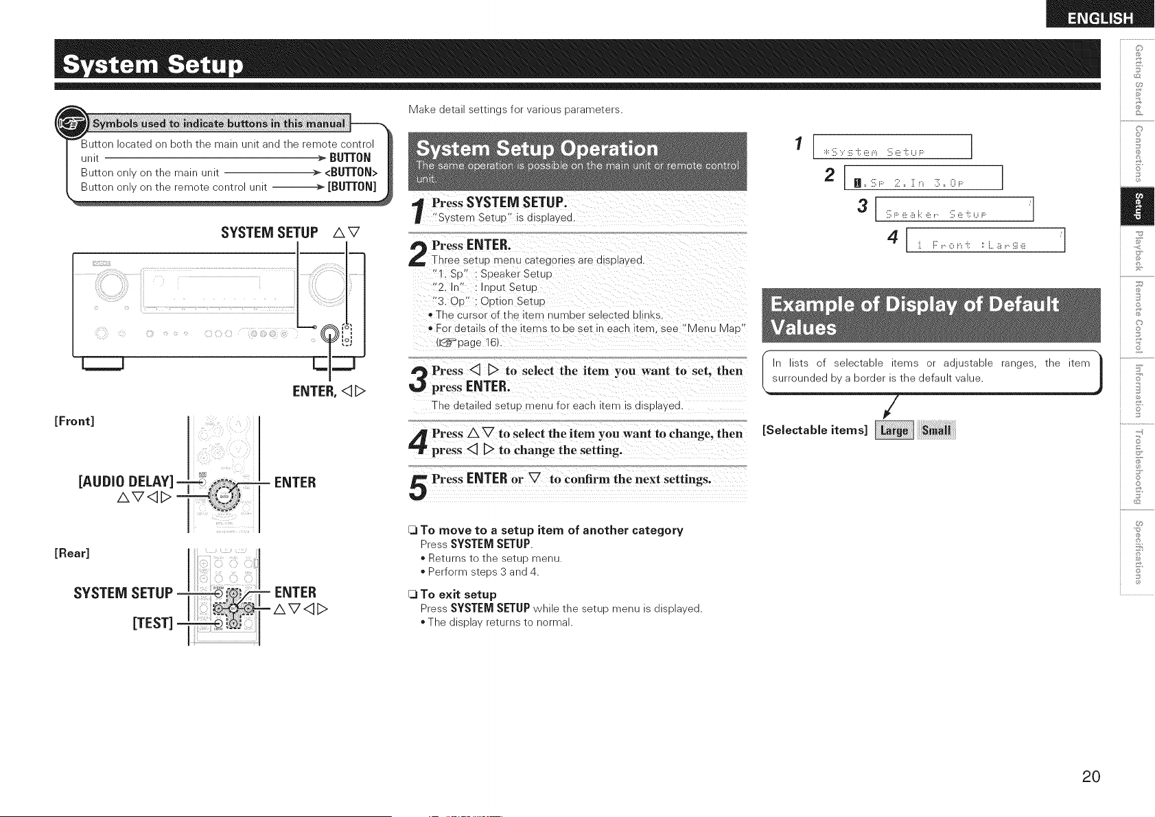
Press SYSTEM SETUP.
"System SetuP" is displa_ea
Press ENTER.
Three setup mev u categor es are alSDla ea.
"1. St)" : SDeakerSetuu
"2. In' : nDut Setuu
"3. OrS : O_3tion Setup
* The cursor of tl_e _err nu qlDer selected DI hKS.
* For details of the items to be set in each item, see "Menu Mat) "
{L_=_page 16).
Press <3 D to select the item you want to set. then
press ENTER.
The aetauea setuo menu for each item is displa_ea
Press/k V to select the item you want to change, then
press <3 D to change the setting.
Press ENTER or V to confirm the next settings.
[3 To move to a setup item of another category
Press SYSTEM SETUP.
Returns tc tne 3etuD menu
>erform steos 3 anq 4.
[3 TO exit setup
Press SYSTEM SETUP while the setup menu is displayed.
* The display returns to normal.
1
:.i.::iill:, :iii:'i:: (ii__"_ :iill(ii_'i:: U F:: ]
2 I H'iiiilF:: 2" ]]i"_ 3"(}i .... 1
3 iiil;F: e a k e v.. iiil;e i:: u i.... "
J. F: i....o i.i '(: :i L 8 i....iii] (ii! "
I surroundedbyaborderistInlists of selectable items or adjustable ranges, the item
he default value.
/
ESe,ectab,e tems
J
©
©
Z
S
jo
©
0
8
2O
[Display]
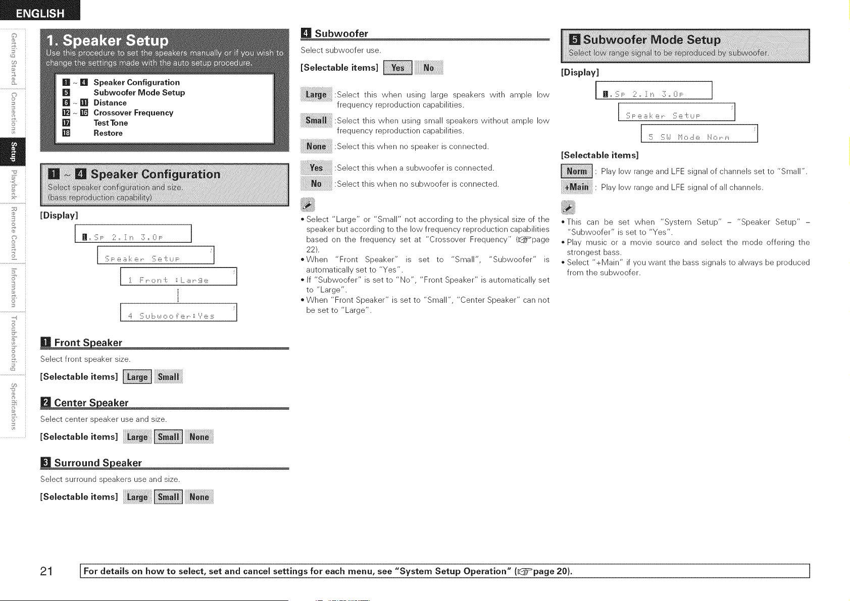
[] Subwoofer
Select subwoofer use.
[Selectable items]
_ :Select this when using large speakers with ample low
frequency reproduction capabilities.
this when using small speakers without ample low
frequency reproduction capabilities.
:Select this when is connected.
no speaker
:Select this when a subwoofer is connected.
:Select this when no subwoofer is connected.
[Display]
n,,'.iil;F 2,, :i:_._ 3,, 0_....
iiillFe .iii_i.:ie _.. iiille i; Ui.... _"
!!!!i iiilli.,.i i"iOcJe i".iO_..f"_ _"
[Selectable items]
• Play low range and LFE signal of channels set to "Small".
Play low range and LFE signal of all channels.
©
2
7
o
5'
2
©
U_
0
In ,, :ill;F 2 ,, :i:__ 3 ,, O_.... 1
iiillF e .iii_i:i e _ iiille i; U i.... _"
i i::'i 0 ii 'ill ii h...iiiii.. iii]_iii!
=::i. iiillU i:::,i.,.i0 0 i: _iii!i.. ii _._.__iii!:iii: "
[] Front S eaker
Select front speaker size.
[Se,ectab,e,tems
[] Center S eaker
Select center speaker use and size.
[Selectable items]
[] Surround S eaker
Select surround speakers use and size.
[Selectable items]
o Select "Large" or "Small" not according to the physical size of the
speaker but according to the low frequency reproduction capabilities
based on the frequency set at "Crossover Frequency" (_page
22).
oWhen "Front Speaker" is set to "Small", "Subwoofer" is
automatically set to "Yes".
If "Subwoofer" is set to "No", "Front Speaker" is automatically set
to "Large".
• When "Front Speaker" is set to "Small", "Center Speaker" can not
be set to "Large".
_This can be set when "System Setup" - "Speaker Setup" -
"Subwoofer" is set to "Yes".
o Play music or a movie source and select the mode offering the
strongest bass.
o Select "+Main" if you want the bass signals to always be produced
from the subwoofer.
21 [For details on how to select, set and cancel settings for each menu, see "System Setup Operation" (_}=page 20). ]
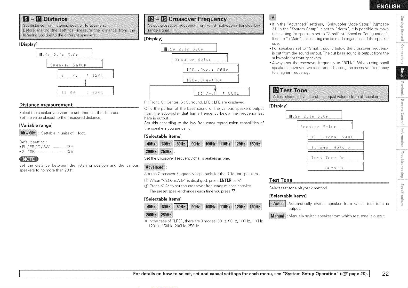
[Display]
In ,, :ill;F: 2 ,, :[ __ :]; ,, 0_.... 1
i]ii;F e a i,::e _,,,, fill;e i:: U i.... "
6 i::'i, ii i, 2 ,i:i:: /
Distance measurement
Select the speaker you want to set, then set the distance.
Set the value closest to the measured distance.
[Variable range]
Settable in units of 1 foot.
!!!!!!!!!!!!!!!!!!!!!!!!!ii
Default setting :
oFL/FR/C/SW ............. 12ft
oSL/SR ............................ 10ft
Set the distance between the listening position and the various
speakers to no more than 20 ft.
[Display]
H=:iil;F: 2= {__ 3;= 0_....
i :ill;F e a i.::e _....:ill;e i::_..._i.... J
._ ...., .... ... ........ .,.,,..:,_ _ /
._ ...., .... ... ........ .,., _,, /
i
i
F : Front, C : Center, S : Surround, LFE : LFE are displayed.
Only the portion of the bass sound of the various speakers output
from the subwoofer that has a frequency below the frequency set
here is output.
Set this according to the low frequency reproduction capabilities of
the speakers you are using.
[Selectable items]
Set the Crossover Frequency of all speakers as one.
Set the Crossover Frequency separately for the different speakers.
_} When "Cr.Over:Adv" is displayed, press ENTER or V.
Press <:1]D to set the crossover frequency of each speaker.
The preset speaker changes each time you press V.
[Selectable items]
•_ In the case of "LFE', there are 8 modes: 80Hz, 90Hz, 100Hz, 110Hz,
120Hz, 150Hz, 200Hz, 250Hz.
o If in the "Advanced" settings, "Subwoofer Mode Setup" (L_=page
21) in the "System Setup" is set to "Norm", it is possible to make
this setting for speakers set to "Small" at "Speaker Configuration".
If set to "+Main', this setting can be made regardless of the speaker
size.
o For speakers set to "Small", sound below the crossover frequency
is cut from the sound output. The cut bass sound is output from the
subwoofer or front speakers.
o Always set the crossover frequency to "80Hz". When using small
speakers, however, we recommend setting the crossover frequency
to a higher frequency.
[Display]
Jl
Jl
Jl
Jl
Test Tone
Select test tone playback method.
[Selectable items]
:Automatically switch speaker from which test tone is
output.
Manually switch speaker from which test tone is output.
@
©
,+,_,
©
S
©
©
15
+-d
S
©
©
I For details on how to select, set and cancel settings for each menu, see "System Setup Operation" (_@=°page 20). I 22
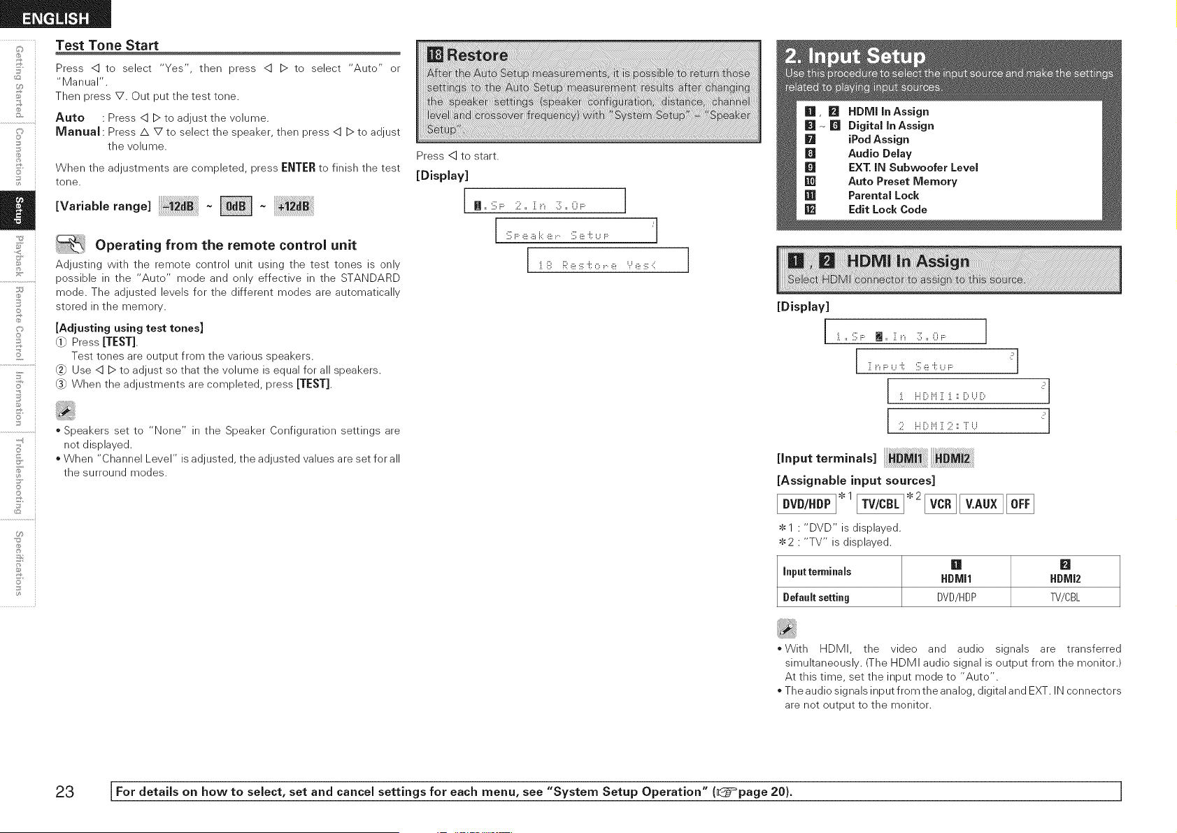
Test Tone Start
Press <] to select "Yes", then press <] D to select "Auto" or
"Manual".
Then press V. Out put the test tone.
Auto • Press <] D to adjust the volume.
Manual Press/k V to select the speaker, then press <] D to adjust
the volume.
When the adjustments are completed, press ENTER to finish the test
tone.
[Va.ab,erang< -
.,¢
O:
i
7
o
5'
]
©
U_
Operating from the remote control unit
Adjusting with the remote control unit using the test tones is only
possible in the "Auto" mode and only effective in the STANDARD
mode. The adjusted levels for the different modes are automatically
stored in the memory.
[Adjusting using test tones]
_ Press [TEST].
Test tones are output from the various speakers.
Use <] D to adjust so that the volume is equal for all speakers.
(_ When the adjustments are completed, press [TEST].
* Speakers set to "None" in the Speaker Configuration settings are
net displayed.
* When "Channel Level" is adjusted, the adjusted values are set for all
the surround modes.
Press <] to start.
[Display]
n ,, :ill;F: 2 ,, ill __ 3 ,, 0_....
j :il;F:e a i_:e _ :ill;e 'i::_...__.... i
I ii. iilil i:;il_iii!:iii:'if:o i.. _iii! Y _iii!:iii:41 l
[Display]
:i.,, '.ill;F: m ,, i[ __ 3 ,, 0_.... I
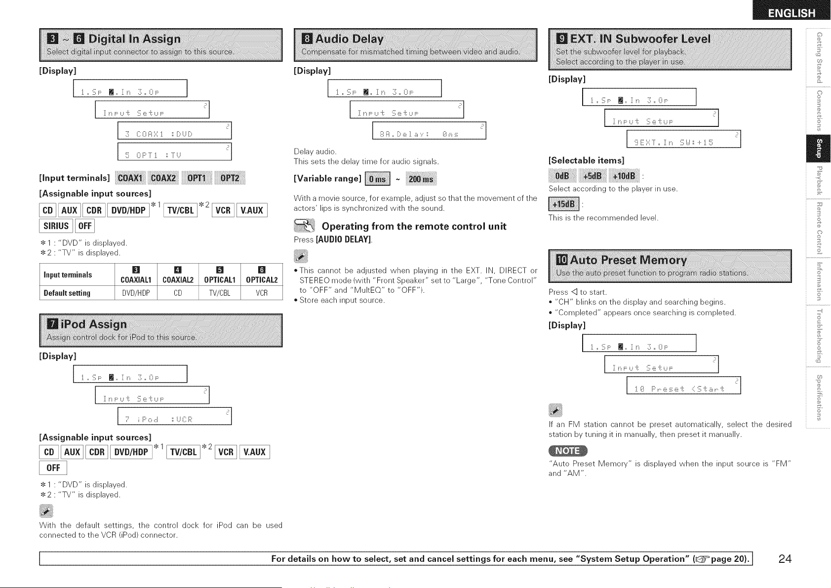
J ii. ii [)M { ii. :: [)_,.,_[) ?
?
,nputterm,n.,.
[AssignabJe input sources]
* 1 " "DVD" is displayed.
2 " "TV" is displayed.
[] B
input terminals HDMJl HDMJ2
Default setting DVD/HDP TV/CBL
=With HDMI, the video and audio signals are transferred
simultaneously. (The HDMI audio signal is output from the monitor.)
At this time, set the input mode to "Auto".
The audio signals input from the analog, digital and EXT. IN connectors
are net output to the monitor.
23 [For detaiJs on how to select, set and cancel settings for each menu, see "System Setup Operation" (_}=_page 20). ]
[Display]
I :i. ,, :ill;F: m ,, :[ i_ :]; ,, 0i .... ]
[Input terminals] _PT_ _T2
[Assignable input sources]
[] DVD/.DP1.1
$1 • "DVD" is displayed.
$ 2 • "TV" is displayed.
[] 81 [] []
Input terminals COAXIAL1 COAXIAL2 0PTICALI 0PTICAL2
Default setting DVD/HDP CD TV/CBL VCR
[Display]
I :i. ,, :ill;F: l_ ,, :[ i_ :]; ,, 0i .... ]
[Assignable input sources]
DVD/.DP1.1
$1 " "DVD" is displayed.
2 " "TV" is displayed.
[Display]
:i. ,, '.ill;F: m ,, :[ i_ :]; ,, 0i ....
[ i: i_F:U 'i:: :ill;e '(. ,...,_.... _']
Delay audio.
This sets the delay time for audio signals.
[Variablerange]
1
With a movie source, for example, adjust so that the movement of the
actors' lips is synchronized with the sound.
Operating from the remote control unit
Press [AUDIO DELAY].
oThis cannot be adjusted when playing in the EXT. IN, DIRECT or
STEREO mode (with "Front Speaker" set to "Large", "Tone Control"
to "OFF" and "MultEQ" to "OFF").
o Store each input source.
[Display]
[:i. ,, :ill;F: i_ ,, :[ i_ :]; ,, 0i .... ]
9 E ):: T ,, { __ :illi.,.i:: + :i.!!!!i
[Selectable items]
Select according to the player in use.
This is the recommended level.
Press <] to start.
* "CH" blinks on the display and searching begins.
* "Completed" appears once searching is completed.
:i. ,, S F: Iii ,, :[ i_ 3; ,, O i.... ]
i[ i_F U 'i:: :ill;,iii_'i::_..._i.... _'
:i.(i!i F::'_..6!:iii:6! '(: :{:ill;'(: ,i£_..'(: _'
If an FM station cannot be preset automatically, select the desired
station by tuning it in manually, then preset it manually.
"Auto Preset Memory" is displayed when the input source is "FM"
and "AM".
C]
©
©
S
Z
©
©
15
+-d
S
©
With the default settings, the control dock for iPed can be used
connected to the VCR (iPed) connector.
I For details on how to select, set and cancel settings for each menu, see "System Setup Operation" (l@=°page 20). [ 24
o
£
o
@
©
2
F'
©
@
U_
@} Press <::].
Using AV<]D, input the password (4 digits number) and press
ENTER.
Set the lock by pressing q _.
:J.,, :ill:F: m ,, :[ i_ 3 ,, Oi.... ]
i[i_F U 'i:: :ill;e i::_..._i.... ?
_ [ :i.:i.F::'a _....e i._i::a ]. L.o c k .::i _
@_)I Code_iX@@@@Xi ?l
(_) :ill;R @@:i. ii .:::U i._]. o ,::::k :::. ?]
:ill;R@@:i. ii .::: L.o ,::::k :::. ?
[SelectabJe items]
: Do not lock selected channel(s).
se,ectedchanne, s
•_ When a Parental Locked channel is tuned, "Code •
displayed, then input the password.
]" is
o The default password is "0000". If you wish to change this password,
set the new password with "Edit Lock Code"
o If the password is incorrectly input, "Incorrect Code" is displayed,
and proceed again from step @}.
* If the password input is 3 digits or less, "Enter 4-digit" is displayed,
and input again with a 4 digit password.
* While listening to the channel being played, you can also set parental
lock (_page 38).
"Parental Lock" is displayed when input source is "SIRIUS" , and
connected to SIRIUSTuner.
@) Press <:].
Input old password (4 digits) using AV<IB>, and press ENTER.
(_) Input new password (4 digits) using AVID, and press [:NTJ:R.
Be sure to memorize the password you have entered.
@} Input new password (4 digits) again using AVID, and press
[:N'[J:R. If the correct password is input, "Complete" is displayed,
and the new password is modified.
[DispJay]
:i.,, :ill;F: m ,, i[ i_ 3 ,, 0i....
i[ i_F U 'i:: :ill;e i::_..._i.... ?
_[ :i.2 E d ii:: L.o ,::::k C o d e .::: ?J
C u ,..,..,iii_i._i::ii iX@@@@Hi ?]
(_ Ne_.,._iliX@:J.23Xi ?
_[ FI:e _:::.e a i::_ i::@:i.2 ::!!:::i ?l
[ 1
,.... ......... ._....._ .....
L., u N i"" .L _:2 _., _:2
If the old password is incorrectly input, "Incorrect Code" is displayed,
and proceed again from step @}.
If the password input is 3 digits or less, "Enter 4-digit" is displayed,
and input again with a 4 digit password.
If the new password is not correctly input, "Disagreement" is
displayed and the password does not change.
"Edit Lock Code" is displayed when the input source is "SIRIUS".
25 [For details on how to select, set and cancel settings for each menu, see "System Setup Operation" (_}=_page 20). ]
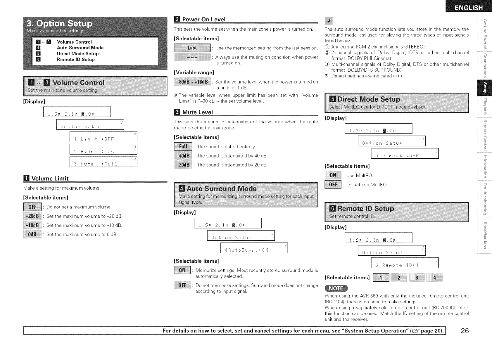
[Display]
i :i. ,, :ill;F: 2 ,, ]: __ M ,, 0_.... 1
[0F:t i,:::,__ :il;ei::U_ .... _'l
:i. L. i _"_i 'i:: :: 0 F::F _'
2 i:::',, 0 i_ :: i.....iii_:iii:'i:: _'
3 i"i u 'i::,iii_ :: F u ]. ]. _'
Volume Limit
Make a setting for maximum volume.
[Selectable items]
• Do net set a maximum volume.
Set the maximum volume to -20 dB.
Set the maximum volume to -10 dB.
Set the maximum volume to 0 dB.
Power On Level
This sets the volume set when the main zone's power is turned on.
[Selectable items]
Use the memorized setting from the last session.
Always use the muting on condition when power
is turned on.
[Variable range]
Set the volume level when the power is turned on
in units of 1 dB.
•_ The variable level when upper limit has been set with "Volume
Limit" is "-80 dB ~ the set volume level"
Mute Level
This sets the amount of attenuation of the volume when the mute
mode is set in the main zone.
[Selectable items]
: The sound is cut off entirely.
Thesound isattenuated by40dB.
Thesound isattenuated by20dB.
[Display]
]...:ill:F:.2.. Zn M..0_....
i 0 F 'i:: i ,:::,i_ :ill;,iii_'i::_..._i....
[ ,::i.i:::iu 'i::o :]i;u r. r. ,, :: 0 i".i _'l
[Selectable items]
• Memorize settings. Most recently stored surround mode is
automatically selected.
Do notmemorize settings.Surroundmode does notchange
accordingto inputsignal.
The auto surround mode function lets you store in the memory the
surround mode last used for playing the three types of input signals
listed below.
_} Analog and PCM 2-channel signals (STEREO)
2-channel signals of Delby Digital, DTS or other multi-channel
format (DOLBY PL[I Cinema)
(_ Multi-channel signals of Dolby Digital, DTS or other multichannel
format (DOLBY/DTS SURROUND)
•_ Default settings are indicated in ().
[Display]
:i.,,:iil;F:. 2,, ]:n m,,(:)_.... I
I
0 i:::'i;io i_ iil;e 'i; u i....
!5 [) i_.. ,iii_,::::'i:: :: 0 F::'F::'
[Selectable items]
i!i!i!i!i!i!i!i!i!i!i!i:_:!i_iiiililililililililili!;i:Use MuItEQ.
: De net use MultEQ.
[Display]
i :i. ,, :ill;F: 2 ,, ]: __ J ,, 0_.... I
0 F 'i::i,:::, i_ :ill;,iii_'i::_..._i.... _'
6 F;;:,iii__"_,:::,'i::,iii_ ill ill:':: :i. _'
When using the AVR-589 with only the included remote control unit
(RC-1104), there is no need to make settings.
When using a separately sold remote control unit (RC-7000CI, etc.),
this function can be used. Match the ID setting of the remote control
unit and the receiver.
©
©
©
©
©
I For details on how to select, set and cancel settings for each menu, see "System Setup Operation" (I]@=°page 20). I 26
7
©
5' i
7
©
Button located on both the main unit and the remote control
unit > BU'N'ON
Button only on the main unit :_ <Bur[0N>
<SELECT/ENTER>,<1D
[Front]
<IL>=
[Rear]
J [STD]
[D/ST]_ _[SIMU]
[PARA]
the surround mode
Select by turning <SELECT/ENTER> or pressing [STD]
[Selectable items]
Thesigna,saredecodedinDOLB PL.for
playback.
Thesigna,saredecodedinDTSN 0:6forp,ayback.
Select the mode to suit the source
Press <SURR. PARA> or [PARA] Display "Mode" and select your
desired mode using <] D.
[3 DOLBY PL][I
This mode is suited for movie sources.
This mode is suited for music sources.
This m ode is suited for games.
:This is the Pro Logic playback mode. This can be
selected when playing with a DOLBY PLH decoder.
When this mode is selected, "DOLBY PL" is
displayed.
[3 DTS NEO:6
This mode is suited for movie sources.
This mode is suited for music sources.
In the case of standard playback of multi channel sources, the AVR-
589 recognizes the format of the multi-channel audio input signal and
automatically operates the appropriate decoder for surround sound.
[Selectable items]
Any of the surround modes in the "Display" column in the following
table.
The mode changes depending upon factors such as the
* Input signal
is being used.
Dolby DOLBY DIGITAL
Digital (other than 2ch) DOLBY DIGITAL
Source
DTS DTS (5.1ch)/ DTS SURROUND
Surround
Source DTS 96/24 DTS 96/24 ( $ )
• This is displayed when the input signal is "DTS 96/24".
o For details, see page 49.
o To select these surround modes using <SELECT/ENTER> or press
[ST[}].
Select the "Cinema", "Music", "Game" and "PL" modes at "Surround
Parameter" - "Mode" (_page 30).
27
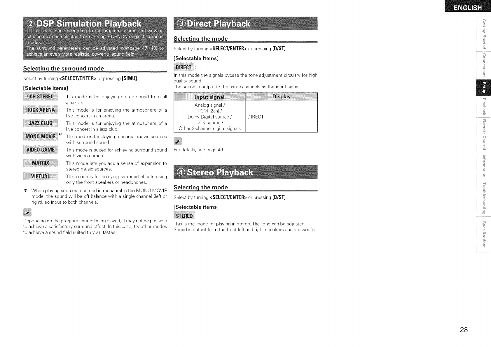
_the surround mode
Select by turning <SELECT/ENTER> or pressing [SIMU]
[Selectable items]
This mode is for enjoying stereo sound from all
; i
speakers.
_RE_ " This mode is for enjoying the atmosphere of a
i
live concert in an arena.
This mode is for enjoying the atmosphere of a
live concert in a jazz club.
: This mode is for playing monaural movie sources
with surround sound.
This mode is suited for achieving surround sound
with video games.
This mode lets you add a sense of expansion to
stereo music sources.
This mode is for enjoying surround effects using
only the front speakers or headphones.
$ : When playing sources recorded in monaural in the MeN© MOVIE
mode, the sound will be off balance with a single channel (left or
right), so input to both channels.
Depending on the program source being played, it may not be possible
to achieve a satisfactory surround effect. In this case, try other modes
to achieve a sound field suited to your tastes.
Seiectin the mode
Select by turning <SELECT/ENTER> or pressing [D/ST]
[Selectable items]
In this mode the signals bypass the tone adjustment circuitry for high
quality sound.
The sound is output to the same channels as the input signal.
Analog signal/
PCM (2ch) /
Dolby Digital source /
DTS source /
Other 2-channel digital signals
DIRECT
For details, see page 49.
Selectin the mode
Select by turning <SELECT/ENTER> or pressing [D/ST]
[Selectable items]
This is the mode for playing in stereo. The tone can be adjusted.
Sound is output from the front left and right speakers and subwoofer.
@
o
©
S
Z
©
©
S
©
28
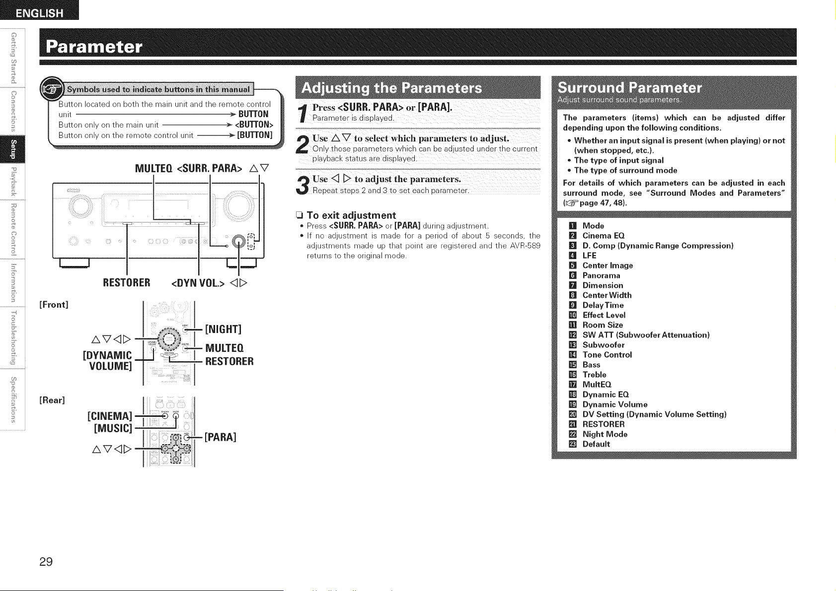
©
5'
Button located on both the main unit and the remote control
unit _ BU'_ON
Button only on the main unit >- <BUT[ON>
MULTEQ <SURR. PARA> AV
[Front]
[Rear]
RESTORER <DYN VOL.> <]D
AV<1D -
[DYNAMIC_
VOLUME]
- [NIGHT]
= MULTEQ
= RESTORER
[CINEMA] _i :
[MUSIC]
AV<1D
VPress <SURR.PARA> 0r [PARA]0
Parameter is displayed.
Use A _ tO select which Parameters to adjust,
On!Y those parameters which Can be adjusted under the current
playbaCk Status are displayed.
_3To exit adjustment
* Press <SURR. PARA> or [PARA] during adjustment.
* If no adjustment is made for a period of about 5 seconds, the
adjustments made up that point are registered and the AVR-S89
returns to the original mode.
The parameters (items) which can be adjusted differ
depending upon the foJJowing conditions.
* Whether an input signaJ is present (when pJaying) or not
(when stopped, etc.}.
* The type of input signaJ
* The type of surround mode
For detaiJs of which parameters can be adjusted in each
surround mode, see "Surround Modes and Parameters"
(L_=_page 47, 48}.
[] Mode
[] Cinema EQ
I[q D. Comp (Dynamic Range Compression)
[] LFE
[] Center image
[] Panorama
[] Dimension
_J Center Width
[] DelayTime
[] Effect LeveJ
[] Room Size
[] SW ATT (SubwooferAttenuation)
[] Subwoofer
[] Tone Control
[] Bass
[] Treble
m MuitEQ
[] Dynamic EQ
[] Dynamic VoJume
[] DV Setting (Dynamic Volume Setting)
m RESTORER
m Night Mode
_J DefauJt
29
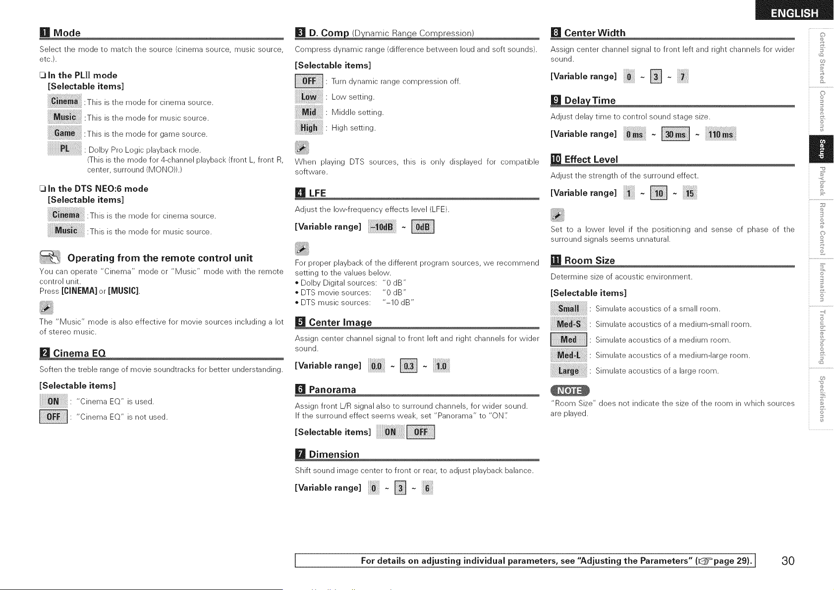
lira Mode
Select the mode to match the source (cinema source, music source,
etc.).
[3 in the PL]] mode
[SeJectabie items]
This is the mode for cinema source.
:This is the mode for music source.
This is the mode for game source.
Dolby Pro Logic playback mode.
!!!!!!!!!!!!!!!!!!!!!!! !
(This is the mode for 4-channel playback (front L, front R,
center, surround (MONO)).)
[3 in the DTS NEO:6 mode
[Selectable items]
This is the mode for cinema source.
This is the mode for music source.
| Operating from the remote control unit
You can operate "Cinema" mode or "Music" mode with the remote
control unit.
Press [CINEMA] or [MUSIC].
The "Music" mode is also effective for movie sources including a lot
of stereo music.
[] Cinema EQ
Soften the treble range of movie soundtracks for better understanding.
[SelectabJe items]
_J'_ " "CinemaEQ"isused.
• "Cinema EQ" is not used.
[] D. Corn (D namic Ran e Corn ression)
Compress dynamic range (difference between loud and soft sounds).
[SelectabJe items]
: Turn dynamic range compression off.
:Lowsetting.
: Middle setting.
: High setting.
When playing DTS sources this is only displayed for compatible
software.
[] LFE
Adjust the low-frequency effects level (LFE).
EVa.ablerang<
For proper playback of the different program sources, we recommend
setting to the values below.
o Dolby Digital sources: "0 dB"
DTS movie sources: "0 dB"
DTS music sources: "-10 dB"
[] Center Ima e
Assign center channel signal to front left and right channels for wider
sound.
Wa.ab erange - []
[] Panorama
Assign front L/R signal also to surround channels, for wider sound.
If the surround effect seems weak, set "Panorama" to "ON'.'
ESe eotab e tems
[] Dimension
Shift sound image center to front or rear, to adjust playback balance.
EVa.ablerang< N-
[] Center Width
Assign center channel signal to front left and right channels for wider
sound.
EVa.ablera°g< N-
[] Dela Time
Adjust delay time to control sound stage size.
IVa.ab erangel -
Effect Level
Adjust the strength of the surround effect.
EVa.ablera°g< []-
Set to a lower level if the positioning and sense of phase of the
surround signals seems unnatural.
Room Size
Determine size of acoustic environment.
[SeiectabJe items]
Simulate acoustics of a small room.
Simulate acoustics of a medium-small room.
• Simulate acoustics of a medium room.
Simulate acoustics of a medium-large room.
; ;
Simulate acoustics of a large room.
"Room Size" does not indicate the size of the room in which sources
are played.
C]
o
©
C)
' Z
©
©
1[?
+-d
©
©
[ For details on adjusting individual parameters, see "Adjusting the Parameters" (l@=°page 29).] 30
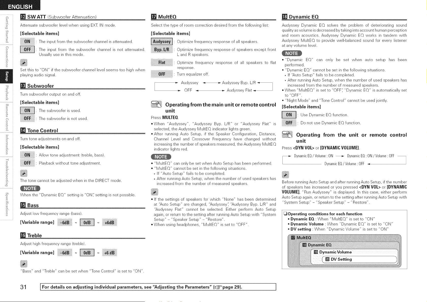
i
o i
©
2
5'
©
° i
.................................i
U_
_=J SW ATT (Subwoofer Attenuation)
Attenuate subwoofer level when using EXT IN mode.
[Seiectable items]
: The input from the subwoofer channel is attenuated.
• The input from the subwoofer channel is not attenuated.
Usually use in this mode.
Set this to "ON" if the subweefer channel level seems tee high when
playing audio signal.
Subwoofer
Turn subwoofer output on and off.
[SelectabJe items]
• The subwoofer is used.
The subwoofer is not used.
Tone Control
Turn tone adjustments on and off.
[SelectabJe items]
Allowtoneadjustment/treNe,bass/.
P,aybackwithouttoneadjustment.
The tone cannot be adjusted when in the DIRECT mode.
When the "Dynamic EQ" setting is "ON;' setting is not possible.
Bass
Adjust low frequency range (bass).
va.ab eran e -
Treble
Adjust high frequency range (treble).
Va.a Iera. e -
MultEQ
Select the type of room correction desired from the following list:
[Selectable items]
Optimize frequency response of all speakers.
Opt,m,zefrequencyresponseofspeakersexceptfront
L and R speakers.
Optimize frequency response of all speakers to flat
response.
Turnequalizeroff
=- Audyssey Audyssey Byp. L/R
]
OFF _ =- Audyssey Flat
Operating from the main unit or remote control
unit
Press MULTEQ
When "Audyssey', "Audyssey Byp. L/R" or "Audyssey Flat" is
selected, the Audyssey MultEQ indicator lights green.
*After running Auto Setup, if the Speaker Configuration, Distance,
Channel Level and Crossover Frequency have changed without
increasing the number of speakers measured, the Audyssey MultEQ
indicator lights red.
* "MultEQ" can only be set when Auto Setup has been performed.
* "MultEQ" cannot be set in the following situations.
, If "Auto Setup" fails to be completed.
, After running Auto Setup, when the number of used speakers has
increased from the number of measured speakers.
If the settings of speakers for which "None" has been determined
at "Auto Setup" are changed, "Audyssey',' "Audyssey Byp. L/R" and
"Audyssey Flat" cannot be selected. Either perform Auto Setup
again, or return to the setting after running Auto Setup with "System
Setup" - "Spea ker Setup" - "Restore".
When using headphones, "MultEQ" is set to "OFF".
_namic EQ
Audyssey Dynamic EQ solves the problem of deteriorating sound
quality as volume is decreased by taking into account human perception
and room acoustics. Audyssey Dynamic EQ works in tandem with
Audyssey MultEQ to provide well-balanced sound for every listener
at any volume level.
"Dynamic EQ" can only be set when auto setup has been
performed.
"Dynamic EQ" cannot be set in the following situations.
, If "Auto Setup" fails to be completed.
, After running Auto Setup, when the number of used speakers has
increased from the number of measured speakers.
When "MultEQ" is set to "OFF',' "Dynamic EQ" is automatically set
to "OFF".
"Night Mode" and "Tone Control" cannot be used jointly.
[SelectabJe items]
: Use Dynamic EQ function.
Do not use Dynamic EQ function.
Operating from the unit or remote control
unit
Press<DYNVOL>or[DYNAMICVOLUME].
DynamicEQ/V01ume: ON _ DynamicEQ: ON/V01ume: OFF
DynamicEQ/V01ume: OFF _
Before running Auto Setup and after running Auto Setup, if the number
of speakers has increased or you pressed <DYN VOL> or [DYNAMIC
VOLUME], "Run Audyssey" is displayed. In this case, either perform
Auto Setup again, or return to the setting after running Auto Setup with
"System Setup" - "Speaker Setup" - "Restore".
_Operating conditions for each function
Dynamic EQ : When "MultEQ" is set to "ON"
Dynamic Volume : When "Dynamic EQ" is set to "ON"
o DV setting : When "Dynamic Volume" is set to "ON"
"Bass" and "Treble" can be set when "Tone Control" is set to "ON".
31 [For details on adjusting individual parameters, see "Adjusting the Parameters" (_:5_page 29). J
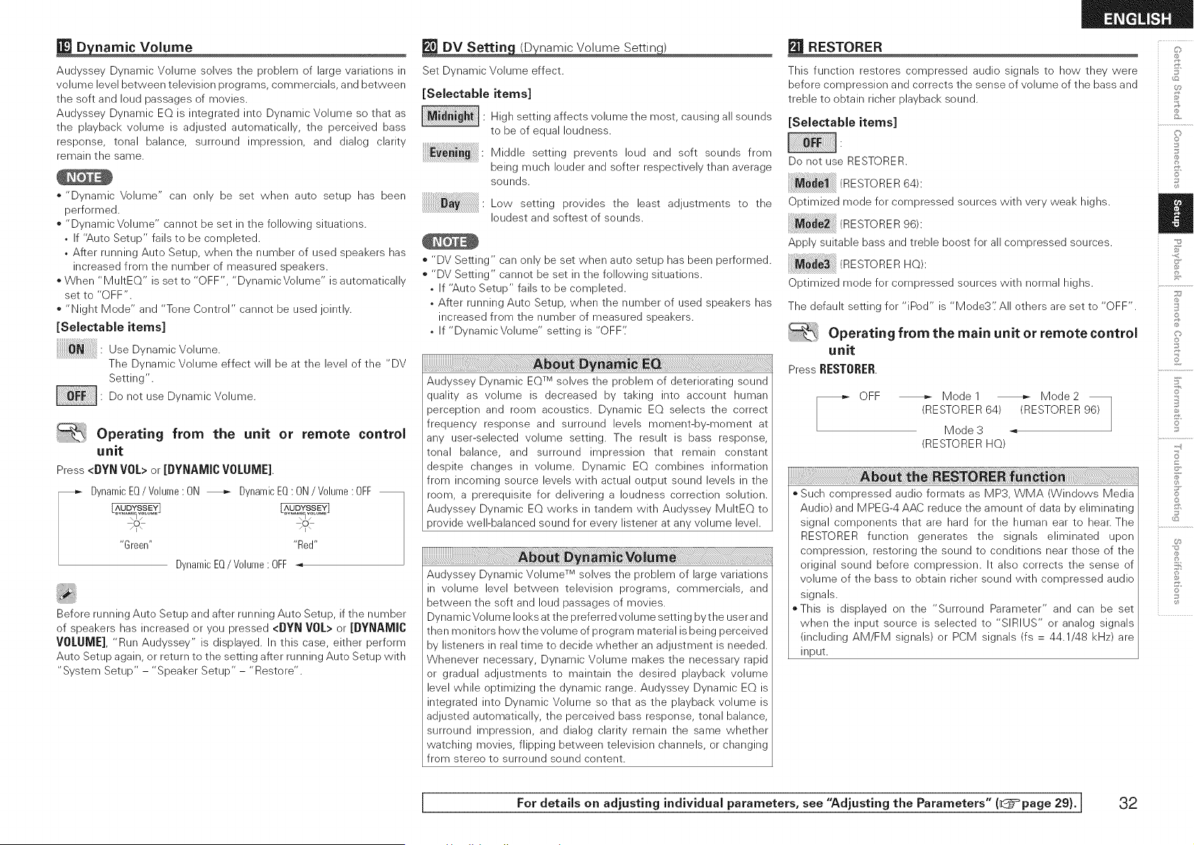
RESTORER _:':,
_namic Volume
Audyssey Dynamic Volume solves the problem of large variations in
volume level between television programs, commercials, and between
the soft and loud passages of movies.
Audyssey Dynamic EQ is integrated into Dynamic Volume so that as
the playback volume is adjusted automatically, the perceived bass
response, tonal balance, surround impression, and dialog clarity
remain the same.
o "Dynamic Volume" can only be set when auto setup has been
performed.
o "Dynamic Volume" cannot be set in the following situations.
• If "Auto Setup" fails to be completed.
• After running Auto Setup, when the number of used speakers has
increased from the number of measured speakers.
o When "MultEQ" is set to "OFF", "Dynamic Volume" is automatically
set to "OFF".
o "Night Mode" and "Tone Control" cannot be used jointly.
[Sebctable items]
Use Dyna m ic V©h m e.
The Dynamic Volume effect will be at the level of the "DV
Setting".
Do not use Dynamic Volume.
Operating from the unit or remote control
unit
Press<DYNVOL>or[DYNAMICVOLUME]
- DynamicEQ/ Volume: ON _ DynamicEQ: ON/ Volume: OFF"Green.... Red"
DynamicEQ/V0hme • OFF
Before running Auto Setup and after running Auto Setup, if the number
of speakers has increased or you pressed <DYN VOL> or [DYNAMIC
VOLUME], "Run Audyssey" is displayed. In this case, either perform
Auto Setup again, or return to the setting after running Auto Setup with
"System Setup" - "Speaker Setup" - "Restore".
Set Dynamic Volume effect.
[Selectable items]
J ia i BiI. N ghsetting affects volume the most, causing all sounds
to be of equal loudness.
Middle setting prevents loud and soft sounds from
being much louder and softer respectively than average
sounds.
Low setting provides the least adjustments to the
loudest and softest of sounds.
o "DV Setting" can only be set when auto setup has been performed.
o "DV Setting" cannot be set in the following situations.
, If "Auto Setup" fails to be completed.
, After running Auto Setup, when the number of used speakers has
increased from the number of measured speakers.
, If "DynamicVohme" setting is "OFF"
Audyssey Dynamic EQTM solves the problem of deteriorating sound
quality as volume is decreased by taking into account human
perception and room acoustics. Dynamic EQ selects the correct
frequency response and surround levels moment-by-moment at
any user-selected volume setting. The result is bass response,
tonal balance, and surround impression that remain constant
despite changes in volume. Dynamic EQ combines information
from incoming source levels with actual output sound levels in the
room, a prerequisite for delivering a loudness correction solution.
Audyssey Dynamic EQ works in tandem with Audyssey MultEQ to
provide well-balanced sound for every listener at any volume level.
Audyssey Dynamic Volume TM solves the problem of large variations
in volume level between television programs, commercials, and
between the soft and loud passages of movies.
Dynamic Volume looks at the preferred volume setting bythe user and
then monitors how the volume of program material is being perceived
by listeners in real time to decide whether an adjustment is needed.
Whenever necessary, Dynamic Volume makes the necessary rapid
or gradual adjustments to maintain the desired playback volume
level while optimizing the dynamic range. Audyssey Dynamic EQ is
integrated into Dynamic Volume so that as the playback volume is
adjusted automatically, the perceived bass response, tonal balance,
surround impression, and dialog clarity remain the same whether
watching movies, flipping between television channels, or changing
from stereo to surround sound content.
This function restores compressed audio signals to how they were
before compression and corrects the sense of volume of the bass and
treble to obtain richer playback sound.
[Selectabb items]
Do not use RESTORER.
RESTORER64 :
Optimized mode for compressed sources with very weak highs.
RESTORER96 :
Apply suitable bass and treble boost for all compressed sources.
TORERN0,:
Optimized mode for compressed sources with normal highs.
The default setting for "iPod" is "Mode3': All others are set to "OFF".
Operating from the main unit or remote control
unit
Press RESTORER.
r_ OFF _ Model _ Mode2
(RESTORER 64) (RESTORER 96)
Mode 3
(RESTORER HQ)
o Such compressed audio formats as MP3, WMA (Windows Media
Audio) and MPEG-4 AAC reduce the amount of data by eliminating
signal components that are hard for the human ear to hear. The
RESTORER function generates the signals eliminated upon
compression, restoring the sound to conditions near those of the
original sound before compression. It also corrects the sense of
volume of the bass to obtain richer sound with compressed audio
signals.
oThis is displayed on the "Surround Parameter" and can be set
when the input source is selected to "SIRIUS" or analog signals
(including AM/FM signals) or PCM signals (fs = 44.1/48 kHz) are
input.
o
©
S
Z
©
©
S
©
I For details on adjusting individual parameters, see "Adjusting the Parameters" (_=page 29). I 32
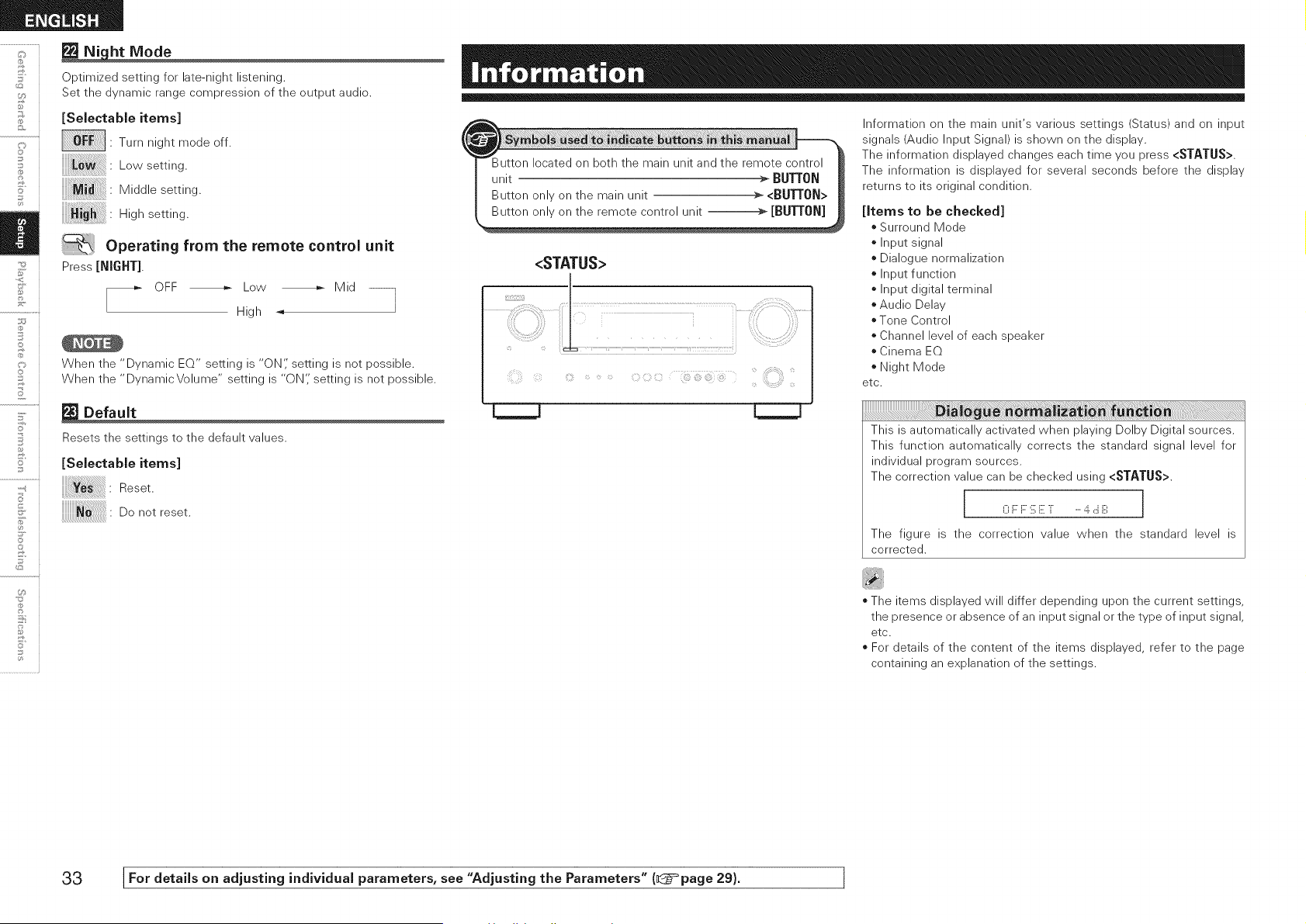
F
©
©
_ht Mode
Optimized setting for late-night listening.
Set the dynamic range compression of the output audio.
[Selectable items]
• Turn night mode off.
:Low setting.
:Middle setting.
: High setting.
Operating from the remote control unit
Press [NIGHT].
OFF _ Low _ Mid --
High -, ]
When the "Dynamic EQ" setting is "ON'; setting is not possible.
When the "Dynamic Volume" setting is "ON'; setting is not possible.
Default
Resets the settings to the default values.
[Selectable items]
Reset.
Donotreset.
<STATUS>
Information on the main unit's various settings (Status) and on input
signals (Audio Input Signal) is shown on the display.
The information displayed changes each time you press <STATUS>.
The information is displayed for several seconds before the display
returns to its original condition.
[Items to be checked]
Surround Mode
o Input signal
o Dialogue normalization
o Input function
o Input digital terminal
Audio Delay
o Tone Control
o Channel level of each speaker
o Cinema EQ
Night Mode
etc.
This is automatically activated when playing Delby Digital sources.
This function automatically corrects the standard signal level for
individual program sources.
The correction value can be checked using <STATUS>.
I 0 i:::i::::iii:E T .....4 ,:::iiiii', J
3
The figure is the correction value when the standard level is
corrected.
o The items displayed will differ depending upon the current settings,
the presence or absence of an input signal or the type of input signal,
etc.
o For details of the content of the items displayed, refer to the page
containing an explanation of the settings.
33 [For details on adjusting individual parameters, see "Adjusting the Parameters" (_page 29). I
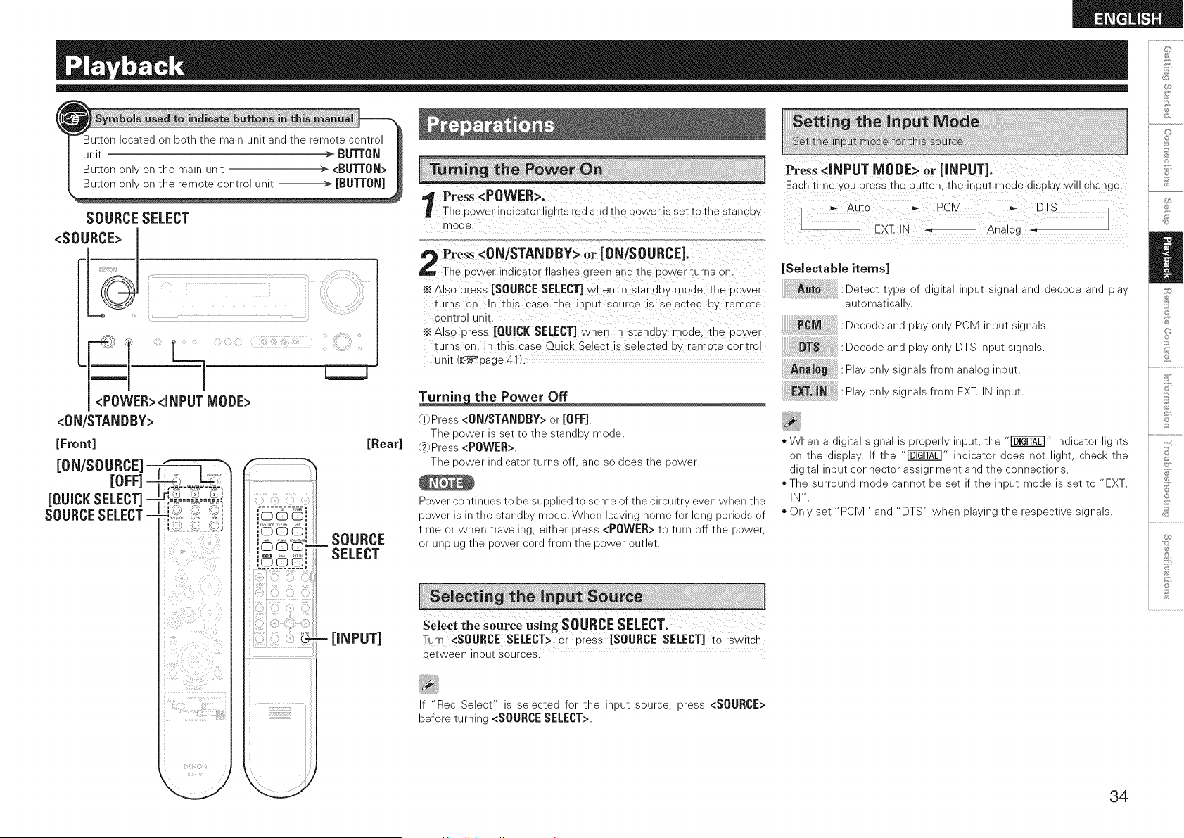
SOURCE SELECT
<SOURCE> J
_WER><iNPUT MODE>
<0N/STANDBY>
[Front]
iON/SOURCE]
[OFF] -
[QUICKSELECT]=
SOURCESELECT-
_j_ _, ,_ ,_ _
G¸. r_ _
,,_ _'_ _'_,,
?ii )iii!!i!i!!;_:'¸ ii!i_!_i_i_i
[Rear]
[iNPUT]
!i!!ii!i!ii!ii!!i!!ii!i!!!!ii
Press <POWER>.
The De Ner indicator ligms red a nd me dower is sez _o me szandw
mode
Press <ON/STANDBY> or iON/SOURCE].
The cower indicator _asnes green and me cower turns or.
•_ Also cress [SOURCE SELECT] when in stanouy mode. me cower
turns on. n this case tne nout source s selected uy remote
control unit.
•_ Also press [QUJCJ( SELECT] when ir standuv mode me cower
turns on. In this case Quick Select is selected o, "emote comro
unit (IL._ aage 41 )
the Power Off
"()Press <ON/STANDBY> or [OFF].
The 9ower is set to me stande _noae.
Press <POWER>.
The cower indicator turns _ff and _o does me cower.
Power continues to be sueened tc some _f the circuitr, even /vnen me
power s _mestande mode. When eavlngnomefor one denods of
time or wnen travenng elmer eress <POWER> to turn off the dower.
or UFOlug the cower cord from the cower OUtleT
Select the source using SOURCE SELECT.
Turn <SOURCE SELECT> or dress [SOURCE SELECT] to switch
between incur sources.
If "Rec Select" is selected for the input source, press <SOURCE>
before turning <SOURCE SELECT>.
Press <iNPUT MODE> or [iNPUT].
Each time you press me _utton the incur mode olsa aywil cnange.
Auto -- PCM DTS
EXq_IN Analog _ ]
[Seleetable items]
:Detecl tvee of _lgltal RDUI slgqa and deCOde and 918v
automatlca
PCM :Decode and elav onw PCM nput signals.
:Decode and elav onw DTS neut signals.
A_aJog :Plav only signals from analog input.
E_T, IN " : Plav only signals from :X_ N _eut.
* ?Vhena ]lglta slgna s 9roeenv nout me _" ndlcator gnts
on me _ISDlaV. _ me "_ ndlcator _oes not gnt cnec_ me
_lglta qDUI connector assignment and me _onnectlons.
* The surround mode :annot De set f the _ou_ mode s set to EXT.
N',
*Onlv set PCM" anc "DTS /vner playing me reseecwe signals.
©
©
Z
©
o
34
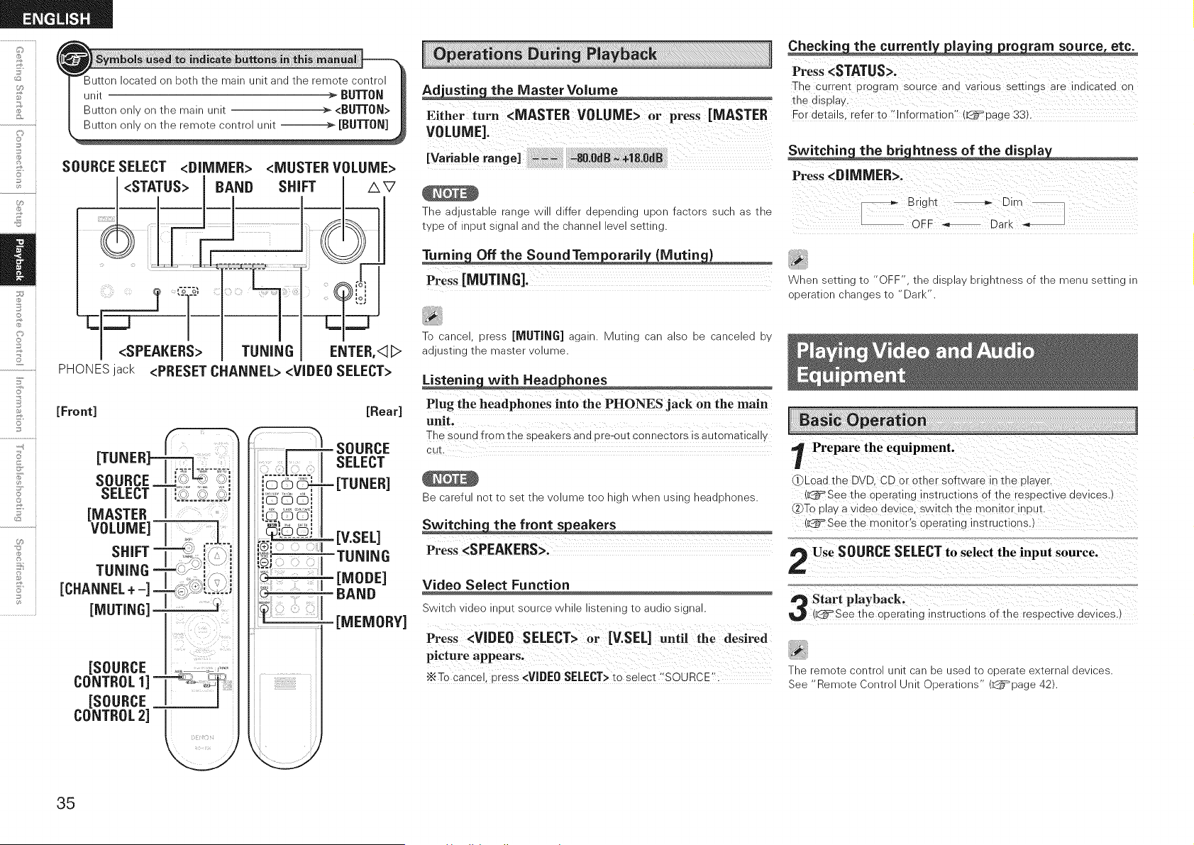
o
©
..........iilL=..i
F'
o
o
SOURCE SELECT <DIMMER> <MUSTER VOLUME>
!<STATUS> I BAND SHIFT /_V
PHONESjack <PRESET CHANNEL> <VIDEO SELECT>
[Front] [Rear]
.................r___5= soURCE
..... SELECT
_. [V EEL]
TUNING
[MODE]
BAND
[MEMORY]
Ad'ustin the MasterVoiume
Either turn <MASTER VOLUME> or press [MASTER
VOLUME].
[VariabJerange] .... _.0dB _÷18.OdB
The aaus;aDle range N differ aepenalng .9on factors sucn as;ne
;vDeof npu;slgna ana;necnanne eve se;;Ing.
Turnin Offthe SoundTem oraril {Mutin )
Press [MUTING].
To cance cress [MUTING] again. Mutino can also _e canceled _,
adJusIIng tne mas_er VOlume.
with Headphones
Plug the headphones into the PHONES jack on the main
unit.
The soun _from the soeaKers and ore-out connectors is automaticall,
cu_
Be =arefu not tc set tne olume too _ gr
Switchin_ the front _eakers
Press <SPEAKERS>.
Nnen using neaQDnones
Video Select Function
Switch video _,)u_ source wnue s_enlng [o aualo signal.
Press <VIDE0 SELECT> or [V.SEL] until the desired
picture appears.
•_To cance, cress <VIDEO SELECT> to select "SOURCE'.
Checkin the currentl la in ro ram source, etc.
Press <STATUS>.
The curren_ urograF source and varioJs se_ings are indicated on
_ne a splay.
For details refer to "information" _=page 33).
Switchin the bri htness of the dis la
Press <DIMMER>.
[_ Bright _ Dirt
OFF _, Dark _,
When setting ;o "OFF" ;ne _lS_la _ngmnessofthemenuse;;inglr
o_era;ion cnanges ;o "Dark
Prepare the equipment.
_Load the DVD. CD or other software in the _laver.
(_See the operating ns_ruc_lons of the respective devices.)
2(_Toplay a video de\ ce. switch the rr onl_or inuu_.
.k_See _he monitor's operating ns_ruc_ions.
Use SOURCESELECTto select the input source.
Start playback.
(k_See the opera_inginstructions of the resoective devices.
The _emote contrc unit can De use(] to oL)era;e external devices.
See "Remote Contro unl; Doera;ions k_=page 42)
35
1 Either_urnselectTUNER".<SOURCESELECT> or press [TUNER] to
,_ Set [SOURCE CONTROL1] to "AUDIO" and [SOURCE
CONTROL2] to "TUNER".
(_=page 42 "Remote Control Unit Ooerations")
Press BAND to select "FM" or "AM".
Tune in the desired broadcast station.
]]To tune in automatically (AutoTuning)
Press [MODE] tc gm the "AUTO" indicator or tne c _play, tnen
Jse TUNING to select tne station you want to near.
_To tune in manually (ManualTuning}
Press [MODE] to turn off the display's "AUTO" ind cator tnen use
1,r[JNING to select the station you want to sear.
* _ tne oeslreo station cannot 9e tuneo _ With auto tuning June t
manua
- When tuning n stations manua v. Dress anc hold TUNING to cnange
I:reouencles continuous
Tune in the broadcast station you want to preset.
Press [MEMORY].
Press SHIFT to select the block _A to G_ in which the
station is to be preset.
Press <PRESET CHANNEL> or [CHANNEL + -] to
select the preset number (1 to 8}.
Press [MEMORY] again to complete the setting.
* To oreset 3tner stations |eDeat steps 1 tO 5.
* Stations can De oreset automatlca at 3vstem Setup
Setuo - "Auto Preset Memor (L_=page 24).
Preset stations are eraseo _ overwriting tnem.
-9UI
Press SHIE[ to select the memory block (A to G).
t_ Press <PRESET CHANNEL> or [CHANNEL + -] to
select the desired preset channel (1 to 8_.
Q Default settings
A1 ~ A8
B1 ~ B8
C1 ~ C8
D1 ~ D8
E1 ~ E8
F1 ~ F8
G1 ~ G8
875 / 89.1 /98.1 / 1029 / 90.1 /90.1 /90.1 /
90.1 MHz
520 / 600 / 1000 / 1400 / 1500 / 1710 kHz,
90.1 / 90.1 MHz
90.1 MHz
90.1 MHz
90.1 MHz
90.1 MHz
90.1 MHz
n
©
36
o
©
F'
o
o
<SOURCE SELECT>
_ _1
_1
I
<ON/STANDBY> <STATUS> TUNING
[Front]
rnFF1
TUNING -
[ENTER]
[AV<II>] _,_:_!i .....
[SOURCE
CONTROL 1] ] _,,_.w_
[SOURCE ]
CONTROL 2] _
/',V
ENTER,<I_>
[Rear]
[SAT TU]
- [iPod]
[TUNING]
[ENTER]
[AV<II>]
[MODE]
What is SIRIUS Satellite Radio?
SimDIv The Best Radio on RadioTM with a ,our favorite emer_alnmen_
ncluung 100_ :ommercial-free music olus suDenor SDOr_Scoverage
uncensored _a _nd _'omea WOrld-ClaSS en_eRalnmem news
tqea_ner and more for /our car name or office. For _nore _formation
Sl_ sirius.cart" or Slrluscanada.ca
Sirius s available - _ne I_ for subscribers Nl_n addresses - _ne
COmlnemal ]S and s available _ Canada for subscribers wl_n a
_anadian address. Reoulred suDscr Duon DlUScomDa_lDle SIRIUS _uner
and amenna are reoulred and SOldseDara_ew. SIRIUS >rogrammlng
SUD ecT _o :nange. ViSl_ sirius.cam for _ne mos_ corrDle_e and LJO-_O-
da_e :nanne neuD and Droauc_ nformation. _IRIUS" and the SIRIUS
dog ago and rela_ed marks are _rademarKs of Sirius Satellite Radio nc.
rlgms _eserved.
1 _ther turn <SOURCE SELECT> or press [SAT TU] to
select "SIRIUS".
Set [SOURCE CONTROL1] to "AUDIO" and [SOURCE
CONTROL2] to"_TUNER".
(L__ page 42 "Remote Ca _trol U nit Oderations"
Use TUNING to search the channel.
When selecting channel, the Channe 'do. and Channe name are
a_sp_ayea.
,_The cnanne swl_cnes comlnuousl Nner" TUNING _ dressed and
neld.
- SIR US Radio s_a_lons can De Drese_ Jslng _ne same orocedure as
for FM AM s_a_lons (L_=page 36 Presetting Radio Stations >resel
Memor' and Listening to Preset Stations
•_ Yoc canno_ oerform "Auto Preset".
- The track name aRis_ name :omooser name category and receD_lOn
eve can De :necKed Dy pressing <STATUS>.
When tuning a channel to which "Parental Lock" is applied, "Code:
[ ]" is displayed, so enter the password.
1 _therturn <SOURCE SELECT> or press [SAT TU] to
select SIRIUS".
" " ' ' " dl la
Press <STATUS> unttl SIG. appears on the "sp y.
_' The display will switch as shown below, depending on the
receotion conditions.
:, ......., StatU_!,
EXCELLENT Signal strength is excellent
GOOD Signal strength is good
WEAK Signal strength is weak
NO SIGNAL No signal
Adjust the position of the antenna until "SIG.:
EXCELLENT" is shown on the d_splavo
Press <STATUS> until the station you want to check
(example: "SRO01") is d_splayed,
Press TUNING and select channel O (SR000).
Channe "lo. and SIRIUS ID are alternate snown on _ne
alS alav,
_SIRIUS ID
•_Write €our own SIRIUS ID for storage use.
SiRiUS ID :
You can :nec_ Satellite anaTerrestria an;enna slgna s;reng;n eacr
;ime _ou dress <STATUS>. On the disDla S" nqlca;es _atellite and
- sdicates Terrestrial.
37
Press [<3
i l
[ -,I I Channel category
use [<3D] to select the category,then use [AV] to
L;, select the desired station.
- JPDATING" s alselavea Nnne _ne encoralng ;ode seemg
undated.
SIRIUS UPDATING" s olselaveo wner Jpoa_lng S RIUS _uner
firmware.
Refer to "Troubleshooting" (L_=page 52) regar@ng diner messages.
r Tune to the channel you want to lock.
I"_ Press [ENTER! for at least 3 seconds.
"Code: [ ]" is dLola_ed
Enter the 4-digit lock code using [/XV<3 D].
Whe_ you enter the correct code, the corresponding cnanne is
OCKed.
Press [ENTER].
. Channels under Parental Lock cannot be tuned in by performing
Tuning Up/Down or by category search.
. Channels stored in preset memory can be tuned in by the preset
channel select operation, even if Parental Lock is applied.
When a channel to which Parental Lock is applied is being played,
Parental Lock for that channel is cancelled by performing Step 2.
. See "Edit Lock Cord" (L_page 25) for the method of changing
Parental Lock Cord.
. You can also set "Parental Lock" from the system setup (L_page
25).
M0_fo, Pod s a _raoemar_ of ADDle _C. reg sterec - _ne U.S
L@J
iPod and diner coumnes.
•_ The Pod ma onlv De used In coev or elav soniems inai are not
ccpyrlgmeo or comems for wnlcrl spying or elaveacl< s legally
3erml_eo for your 3rlvaie use _s an nolvioual. Be sure _o COrTDIV
wlIn aeellcaele :opyrlgm leg slaiion.
[ Make the necessary preparations.
_Set the iPod in t_e DENON contro dock for iPoa.
(L_=See the comrol dOCKfor iPod's operating instructions.)
@Assign the control dock for iPod's input.
The input for the comro dOCK for iPod is assigned to VCR b,
default.
I "System Setup" - "Input Setup" - Assign" t
"iPn_
f_ Either turn <SOURCE SELECT> or press [iPod] to
select the input source assigned in step 1-_ above,
-t _. 99
Set [SOURCE CONTROL1] to AUDIO and [SOURCE
_} CONTROL2] to "iPod/NETWORK'°
(_ page 42 "Remote Contro Unit Ooerations"
I Press [MODE] and hold it down for a 2 seconds or
' more to select the display mode,
Tc switch between modes, Dress and nolo down IRe DU_[OR.
When remote mode is active "Remote" is o spla_ec
[SeJectabJe model Browse mode / Remote mode]
Display location Main unit display iPod display
Playable Audio file O O
files Video file O* 1 O* 2
Active
buttons (AVR-589)
iPod x O
1 : When using an ASD-3N or ASD-3W control dock for iPod
2 : Wdeo may not be output, depen@ng on the combination of ASD-1R
and iPod.
@
£
Ii
,,'With _ne Jefault seeings the iPod ;an ee used ;onnected to theVCR
(iPod connector.
_,use _ne RESTORER mode to exoano _ne ew ann -gn freouencv
comoonems of comoressea audio files anc achieve a richer sound.
The _efault sea,Inn s Mode3" L_=page 32).
Press <0N/SI"AND_Y> or [OFF] and se_ me AVR-SS9's gower _o
_ne s_anae' "node before 31sconneciing IRe Pod. Also SWIICB [Be
neu_ source _o one _o t_nlcn Pod Assign s _o_ assgnea before
_lsconnec_lng _ne Pod.
When using an ASD-3N or ASD-3W comro dock for iPod _efer _o _ne
_esoec_lve manua _o 3eera_e.
Z
S
©
o
8
38
o
©
F'
o
<STATUS>
[Front]
El]
[_] =
[44], [_]=
[144], [_l]-
[ENTER] -
[AV<II>]=
,_=_ ....
i T
7_ii_i_iiii_i'i_!!i!!_i!!?' i_iiiiii!_i!_ii
[Rear]
<i:il)Ciiii,i<iiiD
[TUNING +-]
[iiiiiii; [ENTER]
I'::i_[MODE ]
use [&V]to select the item, then press[ENTER]o r
[_] tOSelect the music file to be played;
Press [ENTER] or [D].
PlaYback starts.
13 Stopping playback temporarily
During playback, press [ENTER] or [_].
Press again to resume playback•
1_ Fast-forwarding or fast-reversing
During playback, press and hold [_] (to fast-reverse) or [_1_] (to
fast-forward).
CI To cue to the beginning of a track
During playback, press [1_11] or [_l].
1_ To stop
During playback, either press and hold [ENTER] or press [_].
CI Playing repeatedly
Press [TUNING-]
Selectab,eite s
CI Shuffling playback
Press [TUNING +]
[se ectab e
To check the name of the title, the artist or the album when playing
in browse mode, press <STATUS>•
=The folder name and the file name can be displayed in browse
mode.Only alphanumeric characters and certain symbols can be
displayed• Any characters that cannot be displayed are replaced with
• (period)'•'
Depending on the type of iPod and the software version, some
functions may not operate•
DENON will accept no responsibility whatsoever for any loss of iPod
data.
an ASD-1R
' Press and hold [MO[}E] to set the Remote mode,
re,,[ENTER] until the !mage yo. want tO view !s
displayed,
"TV Out" at the iPod's "Slideshow Settings" or "Video Settings" must
be set to "On" in order to display the iPod's photo data or videos on
the monitor. For details, see the iPod's operating instructions•
an ASD-3N or ASD-3W
; PreSsa.d hola[MODE]tosetthe _rowsemode,
use[Av] to Select thenpress or
_ [ENTER].
............... <,<, ........
_ use [/xv] tO select the video file t0 be played;then
_ press [_] or[ENTER],
When viewing a still picture, perform the same operation as with ASD-
1R.
39
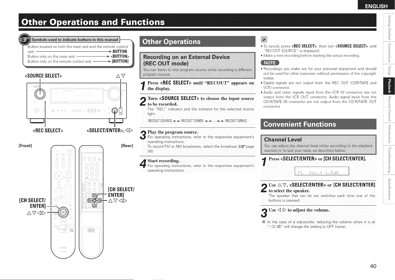
<SOURCESELECT> A V
<RECSELECT>
<SELECT/ENTER>,<1D
[Front] F % _ [Rear]
[CH SELECT/
"!i> _;i,i_!_iiiii!i_
_i(i!_;_ii!_i_iii_i?_ i_ _/_
!!"_!i_ _,_i!,_:
i_?!ill_ 7?
Cii Eiiiiii!ilZ,ii_
[CH SELECT/
ENTER]
AV<I_>
Press <REC SELECT> until "RECOUT" appears on
the display.
Turn <SOURCE SELECT> to choose the input source
to be recorded.
The "REC" indicator and tne indicator for the selected source
gnL
RECOUTSOURCE_ RECOUTTUiXER _ .... _ RECOUT SIRIUS
Play the program source.
For operating nstructions refer to the respective eduiDment's
operating hstrucdor s,
To record ZM or AM broadcasts, se ect tne broadcast (_page
3EL
Start recording.
For operating instrL.cGons, refer to the respective eduiDment's
operating hstrucdons.
C}
* To cance dress <RECSELECT>tnen [urn <SOURCESELECT>unt ,_
"RECOUT 30URCE _dlsDlaved.
* Make a test recordlne before starting tne actua recordlne. _'.
* Recordings ou maKe are for vour gersona evlo_menl and snouid
hot De used for _tner purposes wltnout permission of the copyngnt ,[!,
holder.
* DijIta slgnal_ are not OUtdUt frorr tne REC OUT (CDRq-APE and
VCR connector.
*Au@c and video sgnals nDut from tneVCR N connector are not
outDu_ from tneVCR OUT ;onnector Au@c slgna nDu_ from tne
CD-R TAPE N connector _re not oul_ut from me 3D-F TAPE OUT ;,._
connector
Press <SELECT/ENTER> or [CH SELECT/ENTER/.
[
,e_ Use AV, <SELECT/ENTER> or [CH SELECT/ENTER/ ::_
to select the speaker, i(:,
The speaKer _na_ can De set switches each time one of the o
DUtIOnS s dressed, "
Use <3 D to adjust the volume.
"_ In the case of a subwoofer, reducing tne volume when it is a_
"-12 dB" will change the settin9 to OFF (none
4O
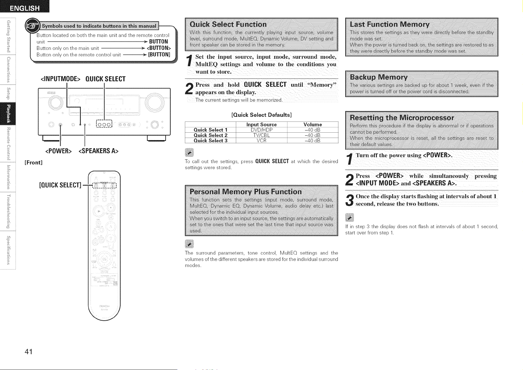
o
©
o
[Front]
<INPUTMODE> QUICK SELECT
<POWER> <SPEAKERSA>
[QUICKSELECT]-
Set the input source, inpu t mode, surround mode,
MultEQ settings and vo!urne to the conditions you
want to Store'
The current settings will be memorized.
[Quick Select Defaults]
Quick Select 1
Quick Select 2
Quick Select 3
Input Source
DVD/HDP
TV/C BL
VCR
Volume
-40 dB
-40 dB
-40 dB
To call out the settings, press QUICK SELECT at which the desired
settings were stored.
The surround parameters, tone control, MultEQ settings and the
volumes of the different speakers are stored for the individual surround
modes.
If in step 3 the display does not flash at intervals of about 1 second,
start over from step 1.
41
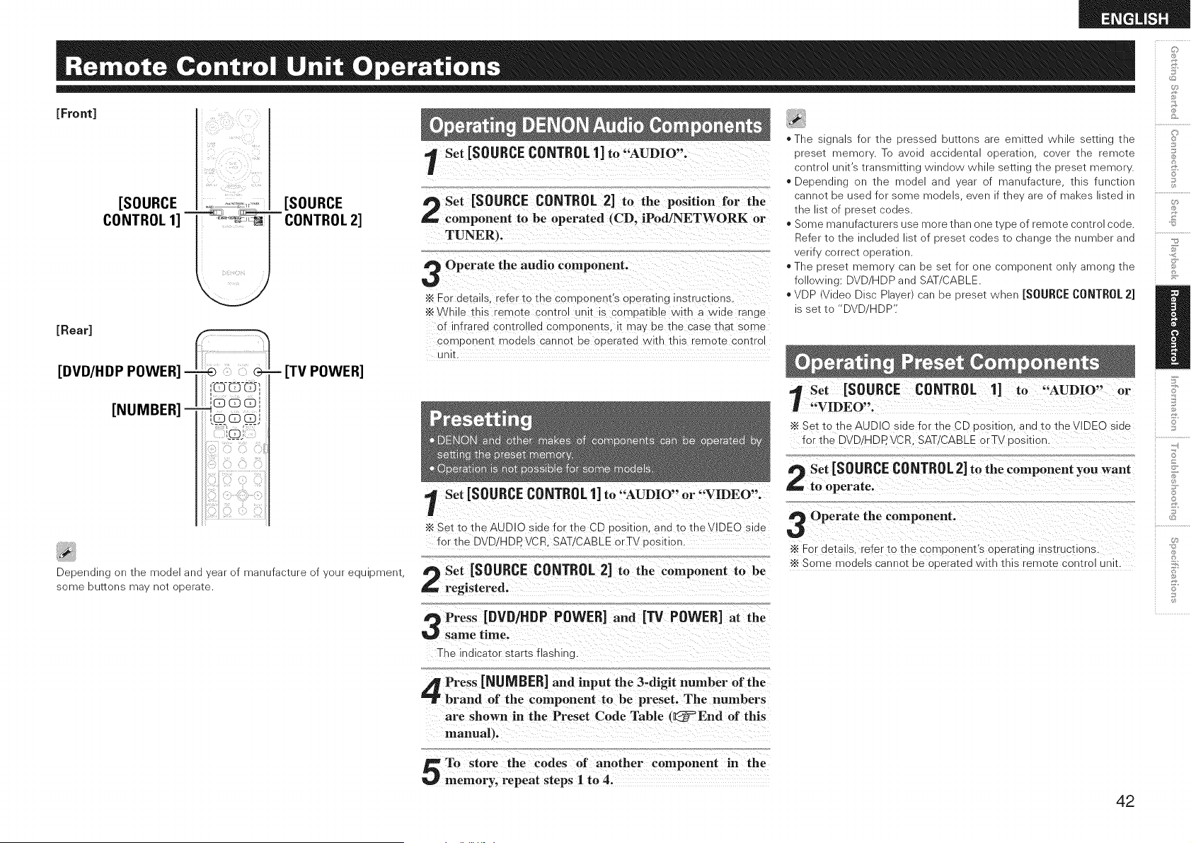
[Front]
[Rear]
i !__il _ ;_ ;_'_'_ii
[SOURCE ._,, _.._r, [SOURCE
CONTROL 1] '''=__ _ CONTROL 2]
- [TV POWER]
Depending on the model and year of manufacture of your equipment,
some buttons may net operate.
Set [SOURCE CONTROL 1] to "AUDIO".
Set [SOURCE CONTROL 2] to the position for the
component to be operated (CD, iPod/NETWORK or
TUNER},
Operate the audio component.
•_ For details. "efer to the comDonent's operating ns_ruct_ons
•_ W k; e this remote control unit is compatible with a wide range
of infrared controlled comDonems [ may De tne case tnat some
comDonem models cannot oe oueratea with this remote centre
unit.
l Set [SOURCE CONTROL1] to "AUDIO" or "VIDEO".
•_ Set to the AUDIO side for the CD position, and to tNeVIDEO side
for the DVD/HDP. VCR. SAT/CABLE orTV oosldon.
Set [SOURCE CONTROL 2] to the component to be
registered.
Press [DVD/HDP POWER] and [13/ POWER] at the
same time.
The indicator starts flashino.
* The s gnal_ for tne oressea outtons are eml_ea Wnlle setting me
oreset memor . To aVOid 9cciqenta 3Deratlon cover me _emote
centre Jnlt s transmitting WlndOV_ While setting tne oreset memor.
Depending on tne "node and ear of manufacture tnls functior
cannot De used for some models ever _tne are _f maKes listed "
tne liSt of preset codes.
Some manufacturers use more [nan one type of remote control code.
Refer to tne nClUded st of t)rese] COdeStc cnange tne number and
verif v correct operation.
* The 3reser memor can 3e set for one :omDonenr only among [ne
following: DVD.HDP and SAT CABLE.
* VDP video Disc Pl_ver/can ge greset wnen [SOURCE CONTROL 2]
3 set to "DVE HDP':
't Set [SOURCE CONTROL 1] to "AUDIO" or
"VIDEO".
"_ Set tc the AUDIO side for the CD _osmon. and to the VIDEO side
for the DVD/HDP. VCR. SAT!CABLE orTV dosidon.
Set [SOURCE CONTROL2] to the component you want
to operate.
Operate the component.
•_ For details refer to the corr oonent's operating instructions.
•_ Some models cannot be ooeratea with this "emote control unit.
©
o
S
o
Press [NUMBER] and input the 3-digit number of the
brand of the component to be preset, The numbers
are shown in the Preset Code Table t_=End of this
manual).
To store the codes of another component in the
memory, repeat steps I to 4.
42
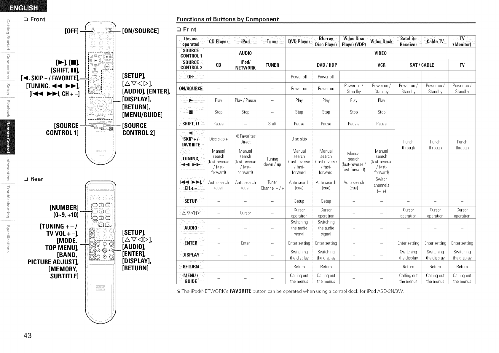
[OFF] -
&
©
+,©
S
/
5'
7
2
[==],
[SHIFT, II],
[_1, SKIP+ / FAVORITE],=
[TUNING, 44 I_1_],
[1<14 IH_I, CH+-]
[SOURCE =
CONTROL 1]
[3 Rear
@
U_
[NUMBER]
(0~9, +10)
[TUNING +-/
TV VOL + -],
[MODE,
TOP MENU],
[BAND,
PICTURE ADJUST],
[MEMORY,
SUBTITLE]
,b {i{!}!;{LY_i
.....j_-_ .....
- d
• S
I;u;
i i
ri55}t_Aid
- FeN/SOURCE]
[SETUP],
[AVqI>],
[AUDIO], [ENTER],
_ [DISPLAY],
[RETURN],
[MENU/GUIDE]
- [SOURCE
CONTROL 2]
[SETUP],
[AVq_],
[AUDIO],
[ENTER],
[DISPLAY],
[RETURN]
Functions of Buttons _onent
[3 Fr nt
Device'....., ;....,. ..... Blu,ray Video Disc Satellite i, TV
uvu r!ayer ! Disc Player Player(vBP) video Beck Receiver llvlonltor)
operated i,u r ayer re! !u.er _ . z.awe Iv .. ; ,
SOURCE
CONTROL1 AUDIO VIDEO
SOURCE iPod/
CONTROL2 CB NETWORK VCR SAT / CABLE TV
OFF .....
v,,,ouu_,Lr_";t_'Rr": - - Poweron/ Poweron/ Poweron/
Standby Standby Standby
TUNER
Shift
Poweroff
Poweron
Play
Stop
Pause
DVD / HDP
Poweroff
Poweron
Play
Stop
Pause
Poweron /
Standby
Play
Stop
Pause
Poweron/
Standby
Play
Stop
Pause
Play Play/ Pause
m Stop Stop
SHIFT,il Pause
SKIP+] Discskip+ '_ Favorites Discskip - - -
Direct
FAVORITE
Manual Manual Manual Manual Manual
TUNING search search search search Manual search
search (fast-reverse
4_ _ (fast-reverse (fast-reverse Tuning (fast-reverse (fast-reverse (fast-reverse/
/ fast- / fast- down / up / fast- / fast- / fast-
forward) forward) forward) forward) fast-forward) forward)
Punch
through
14,,_ _l,
CH÷-
Auto search
(cue)
Tuner
Channel- / +
Auto search
(cue)
Cursor
Enter
Auto search
(cue)
i Autosearch
i (cue)
Auto search
(cue)
Switch
channels
(-,4
Punch
through
Punch
through
SETUP - Setup Setup ....
Cursor Cursor Cursor Cursor Cursor
,£'741> - -
operation operation operation operation operation
Switching Switching
AUDIO - - the audio the audio .....
signal signal
ENTER - - Entersetting Entersetting - - Entersetting Entersetting Entersetting
ni¢oi,_Vu,,,.,.,.,. - _ Switching Switching _ _ Switching Switching Switching
the display the display the display the display the display
RETURN - - Return Return - - Return Return Return
MENU/ _ _ Callingout Callingout _ _ Callingout Callingout Callingout
GUIDE the menus the menus the menus the menus the menus
•_ The iPod/NETWORK's FAVORITE button can be operated when using a control dock for iPod ASD-3N/3W.
43
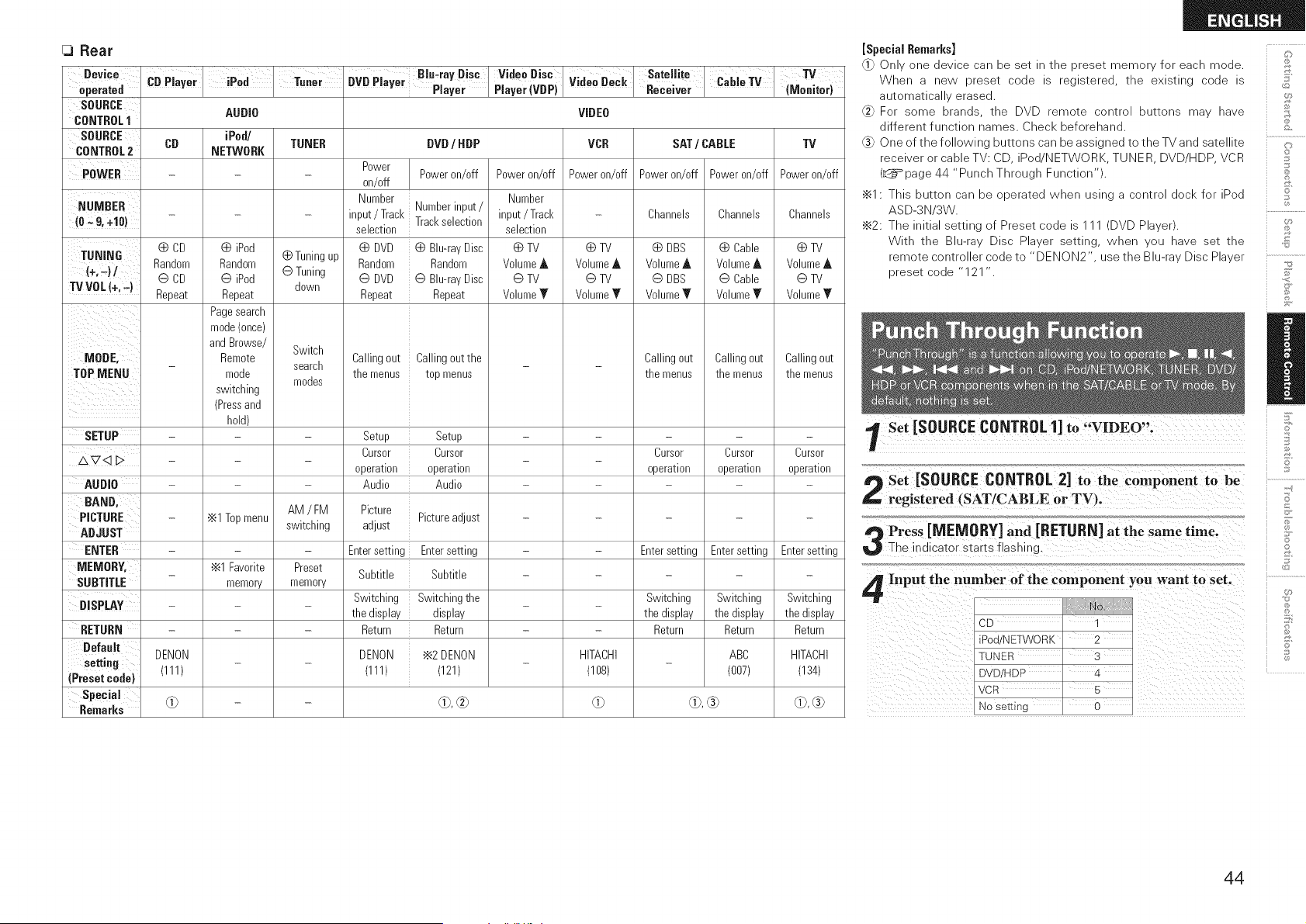
Rear
Device '^, ,; I
D".r.t.d _.,,r.yer
SDURCE
CONTROL1
SOURCE
CONTROL2 CB
POWER
iPod I Tuner
D..... Biu.ray Disc
vu rlayer Player
DVD/ HDP
Power
Poweron/off
on/off
Number
Numberinput/
input/Track Trackselection
selection
Video Disc
Player (VBP)
AUDIO
iPed/
TUNER
NETWORK
0 iPod
Random 0 Tuningup
@ iPod @ Tuning
down
Repeat
Pagesearch
mode(once)
andBrowse/ Switch
Remote
search
mode
modes
switching
(Pressand
hold)
AM / FM
•_1 Topmenu switching
•_1 Favorite Preset
memory memory
Poweron/off
VideoDeCk
VIDEO
VCR
Poweron/off
Satellite ,; _.
ReCeiver _a"e ,v
SAT/ CABLE
TV
(Meuitor)
TV
Poweron/off
Number
NUMBER _ input/Track - Channels
(O*,9, +10) selection
0 CD (_ DVD (_ Blu-rayDisc (_ TV (_ TV (_ TV
TUNING
(+,_) / Random Random Random VolumeA VolumeA Volume_
@ CD @ DVD @ Blu-rayDisc @ TV @ TV @ TV
TV VDL (+,-) Repeat Repeat Repeat Volume_r Volume_r Volume_r
Callingout Callingoutthe
the menus top menus
Poweron/off Power on/off
Channels Channels
(_ DBS (_ Cable
VolumeA VolumeA
@ DBS @ Cable
Volume_' Volume_'
Callingout Callingout
the menus the menus
Cursor Cursor
operation operation
Entersetting Entersetting
Switching Switching
the display the display
Return Return
ABC
(007)
MODE,
TOPMENU
Callingout
the menus
SETUP - Setup Setup - - -
Cursor Cursor Cursor
AV<_D - - -
operation operation operation
AUDIO - Audio Audio - - -
BAND' Picture
PICTURE - Pictureadjust - -
ADJUST adjust
ENTER - Entersetting Entersetting - - Entersetting
MEMORY. _ Subtitle Subtitle - - -
SUBTITLE
DISPLAY - Switching Switching the _ _ Switching
the display display the display
RETURN - Return Return - - Return
Default DENON DENON '_2 DENON HITACHI HITACHI
setting (111) (111) (121) - (108) (134)
(Presetcode)
Special
Remarks O) 0), _ O) 0), (_ 0), (_
[Special Remarks]
"1 Onlv )ne 3evlcecan oeset - me 9reser memor foreacn mode.
When a new oreset code s reg sterea me exlstlno _-oae s ,ii:J
automatlca erased.
".2 For some oranas me DVD remote centre Duuons ma' nave
Jifferent function qames. Checl< beforehand.
One of the following Duuons car De asslonea to me TV and satellite 4,
recelverorcableTV:CD Dec NETWORK TUNER DVD/HDP VCR !_(
(_page 44 "Punch Througr Function" !}:i
•_1- This ouuon can _e ooeratea wner Jslng _ centre ]oc_ for Pod !_
ASD-3N '3W.
u,
•_2: The nltla seulno of Preset code S (DVD Pla erh !;_
With me Blu-ra Disc Plaver setting, wnen _u nave set me _il
remote controller code to "DENON2 Jse me Blu-ra _/Disc Plaver
oreset ;oae "121
l Set [SOURCE CONTROL 1]
Set [SOURCE CONTROL 2] to the component to be
registered (SAT/CABLE or TV).
Press [NIEMORY] and [RETIJRN] at the same time.
The indicator starts flashing.
Input the number of the component you want to set.
CD 1
iPod/NETWORK 2
]UNER 3
DVD/HDP 4
VCR 5
No setting 0
©
©
44
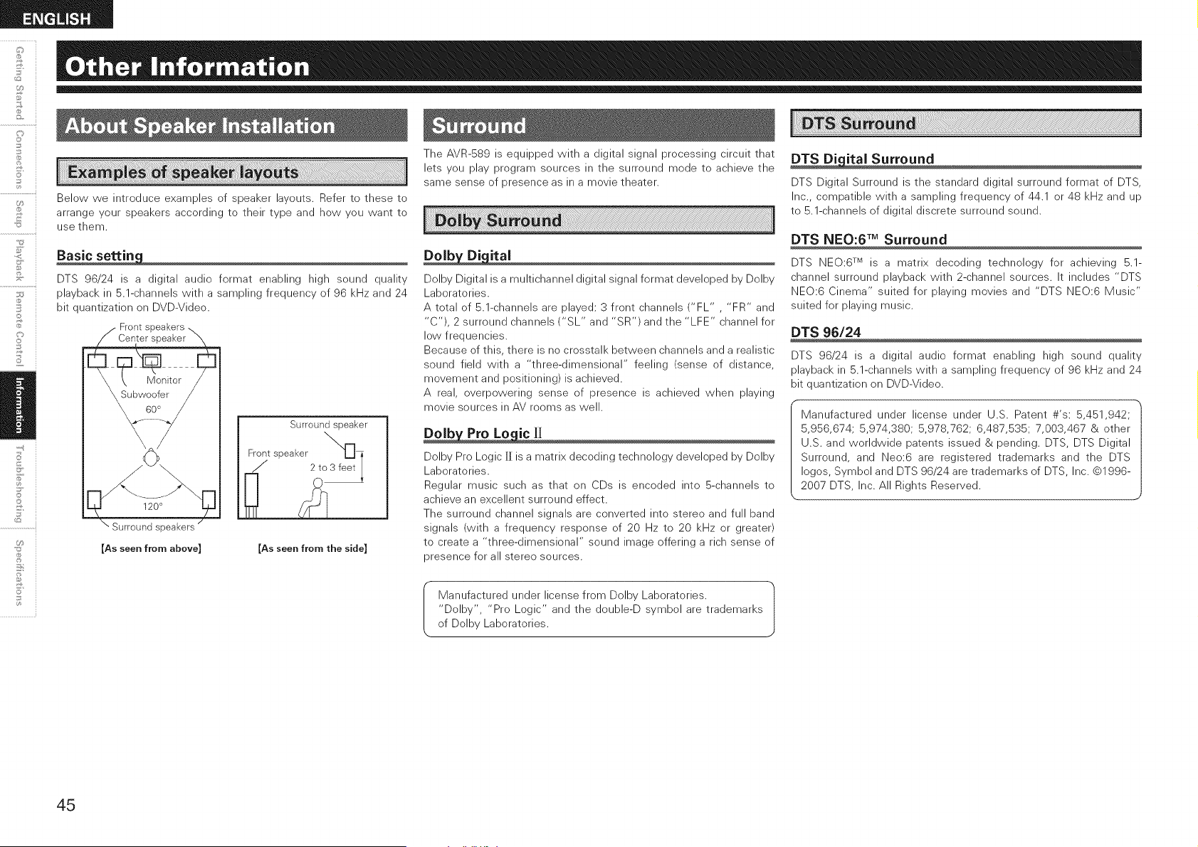
+,©
©
U_
Below we introduce examples of speaker layouts. Refer to these to
arrange your speakers according to their type and how you want to
use them.
DTS 96/24 is a digital audio format enabling high sound quality
playback in 5.1-channels with a sampling frequency of 96 kHz and 24
bit quantization on DVD-Video.
Front
120°
Surround speakers
[As seen from above]
Surround speaker
Front/speaker 2to_ i
[As seen from the side]
The AVR-589 is equipped with a digital signal processing circuit that
lets you play program sources in the surround mode to achieve the
same sense of presence as in a movie theater.
_ital
Dolby Digital is a multichannel digital signal format developed by Dolby
Laboratories.
A total of 5.1-channels are played: 3 front channels ("FL" , "FR" and
"C'), 2 surround channels ("SL" and "SR') and the "LFE" channel for
low frequencies.
Because of this, there is no crosstalk between channels and a realistic
sound field with a "three-dimensional" feeling (sense of distance,
movement and positioning) is achieved.
A real, overpowering sense of presence is achieved when playing
movie sources in AV rooms as well.
Dolb Pro Lo ic][I
Dolby Pro Logic [] is a matrix decoding technology developed by Dolby
Laboratories.
Regular music such as that on CDs is encoded into 5-channels to
achieve an excellent surround effect.
The surround channel signals are converted into stereo and full band
signals (with a frequency response of 20 Hz to 20 kHz or greater)
to create a "three-dimensional" sound image offering a rich sense of
presence for all stereo sources.
Manufactured under license from Dolby Laboratories.
"Dolby', "Pro Logic" and the double-D symbol are trademarks
of Dolby Laboratories.
DTS Di ital Surround
DTS Digital Surround is the standard digital surround format of DTS,
Inc., compatible with a sampling frequency of 44.1 or 48 kHz and up
to 5.1-channels of digital discrete surround sound.
DTS NEO:6 TM Surround
DTS NEO:6 TM is a matrix decoding technology for achieving 5.1-
channel surround playback with 2-channel sources. It includes "DTS
NEO:6 Cinema" suited for playing movies and "DTS NEO:6 Music"
suited for playing music.
DTS 96/24
DTS 96/24 is a digital audio format enabling high sound quality
playback in 5.1-channels with a sampling frequency of 96 kHz and 24
bit quantization on DVD-Video.
Manufactured under license under U.S. Patent #'s: 5,451,942;
5,956,674; 5,974,380; 5,978,762; 6,487,535; 7,003,467 & other
U.S. and worldwide patents issued & pending. DTS, DTS Digital
Surround, and Neo:6 are registered trademarks and the DTS
Iogos, Symbol and DTS 96/24 are trademarks of DTS, Inc. ©1996-
2007 DTS, Inc. All Rights Reserved.
45
IVlu JtEQ®
Audyssey MuItEQ is a room equalization solution that calibrates any
audio system so that it can achieve optimum performance for every
listener in a large listening area. Based on several room measurements,
MultEQ calculates an equalization solution that corrects for both
time and frequency response problems in the listening area and also
performs a fully automated surround system setup.
Aud sse D namic EQTM
Audyssey Dynamic EQ solves the problem of deteriorating sound
quality as volume is decreased by taking into account human perception
and room acoustics. Audyssey Dynamic EQ works in tandem with
Audyssey MultEQ to provide well-balanced sound for every listener
at any volume level.
Aud sse D namicVolume TM
Audyssey Dynamic Volume solves the problem of large variations in
volume level between television programs, commercials, and between
the soft and loud passages of movies.
Audyssey Dynamic EQ is integrated into Dynamic Volume so that as
the playback volume is adjusted automatically, the perceived bass
response, tonal balance, surround impression, and dialog clarity
remain the same.
Manufactured under license from Audyssey Laboratories. U.S.
and foreign patents pending. Audyssey MultEQ @ is a registered
trademark of Audyssey Laboratories. Audyssey Dynamic EQTM is a
trademark of Audyssey Laboratories. Audyssey DynamicVolume TM
is a trademark of Audyssey Laboratories.
HDMI is a digital interface standard for next generation TVs based
on DVI (Digital Visual Interface) standards and optimized for use in
consumer equipment.
Non-compressed digital video and multi-channel audio signals are
transmitted with a single connection.
HDMI is also compatible with HDCP (High-bandwidth Digital Contents
Protection), a technology for protecting copyrights that encrypts digital
video signals in the same was as with DVI.
Color
Eliminates on-screen color banding, for smooth tonal transitions and
subtle gradations between colors.
Enables increased contrast ratio.
Can represent many times more shades of gray between black and
white.
At 30-bit pixel depth, a four times improvement would be the minimum,
and the typical improvement would be eight times or more.
×vYCC
Next-generation "xvYCC" color space supports 1.8 times as many
colors as existing HDTV signals.
Lets HDTVs display colors more accurately.
Enables displays with natural, vivid colors.
I "HDMI'; "HDMI logo" and "High-Definition Multimedia Interface" |
h
are trademarks or registered trademarks of HDMI Licensing LLC.
J
@
@
©
3
©
S
S
Ii
S
©
46
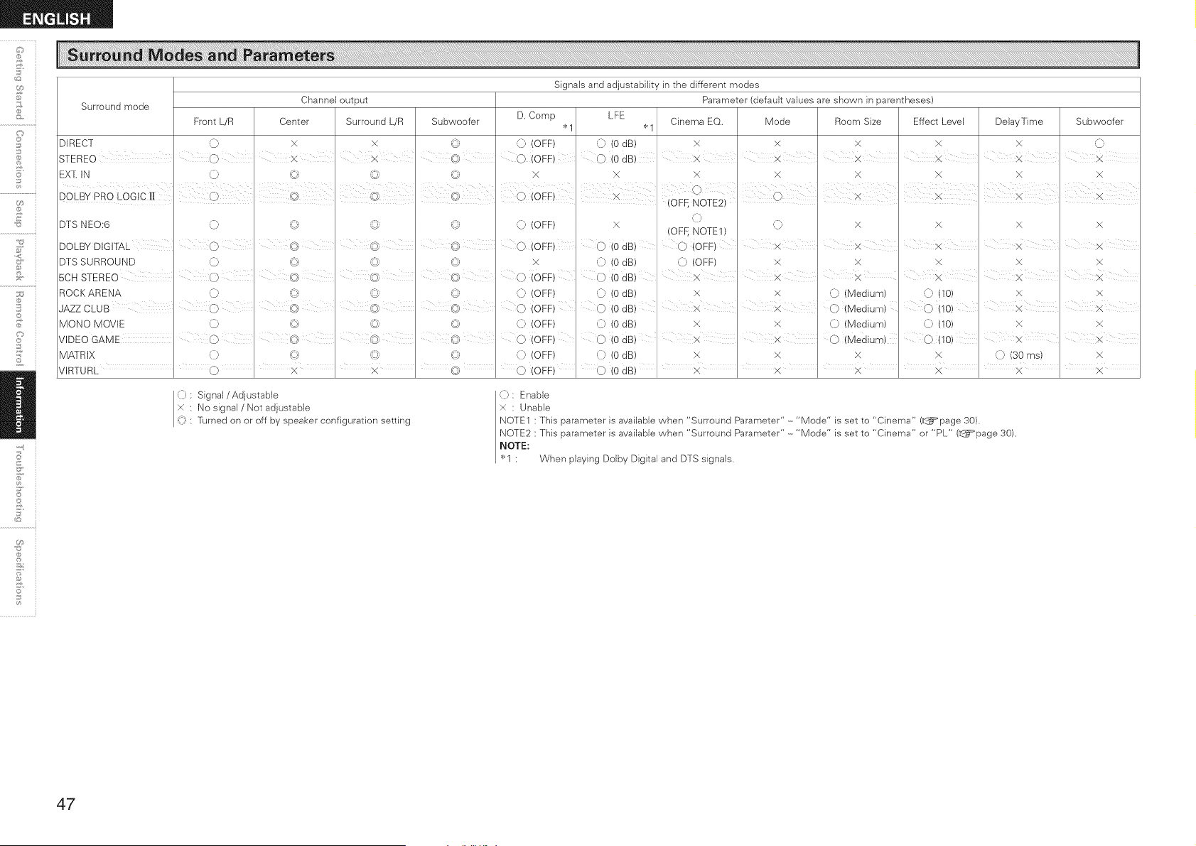
Signals and adjustability in the different modes
Surround mode Channel output Parameter (default values are shown in parentheses)
Front L/R Center Surround L/R Subwoofer D. Comp LFE
>_1 >_, Cinema EO< Mode Room Size Effect Level DelayTime Subwoofer
DIRECT '0 X x _ (i, (OFF) (i) (0 dB) >( x X X X '0
STEREO i C} x I x ' ' 0 OFF 0 (0 IdB) , X X X × I £ iX
EX[ IN (i) '{d © _ X X x: X X X x x:
DTS N E0:6 ,(]) © © {/; (:)
DOLBY DIGITAL (7 ' ©<' ' © _ @
DTS SURROUND '0 '9 ©
5CH STEREO I () (c}) ¢}) (_1) 0
R0 CK A R ENA '0 (_i '9 © (}
i <, i
JAZZ CLUB I 0 © © @ 0
MONO MOVIE '9 '(_3 '_-_; @ (}
VIDEO GAME () @ 0
M A] R IX '0 '_d '_ © '0
, , , , ,
VIRTURL 0 × ' x ' (_} 0
(OFF)
O
x 0
iOFF) 0
(OFF) (
(OFF) O
(OFF) ()
(OFF) O
(OFF) (}
(OFF) 0
x
_0
(0
_0
(0
(o
(o
(o
(o
,(])
(} x x × x
(OFf, NOTE1)
dB) C) (OFF) ' x I x ' x i × X
dB) (]) (OFF) × x x x x
i i i i
dB) X X ' X X X X
dB) x × '0 (Medium) ((10) x: x
dB) × '2 0 (Medium)0(10)x
dB) x )4 '0 (Medium) (]) (10) X x:
dB) X ' X O(Mediura) ' 0(10) X X
dB) X X X X 0 (30 ms) X
, , , , , ,
dB) x x ' × ' x ' x ' x
o
U9
11;
(]) : Signal / Adjustable
× : No signal / Not adjustable
_]) 'Pdrned on or off by speaker configuration setting
(): Enable
× : Unable
NOTE1 : This parameter is available when "Surround Parameter" -"Mode" is set to "Cinema" (L_=page 30)
NOTE2 : This parameter is available when "Surround Parameter" -"Mode" is set to "Cinema" or "PL" (L_=page 30).
NOTE:
"_<1 : When playing Dolby Digital and DTS signals.
47
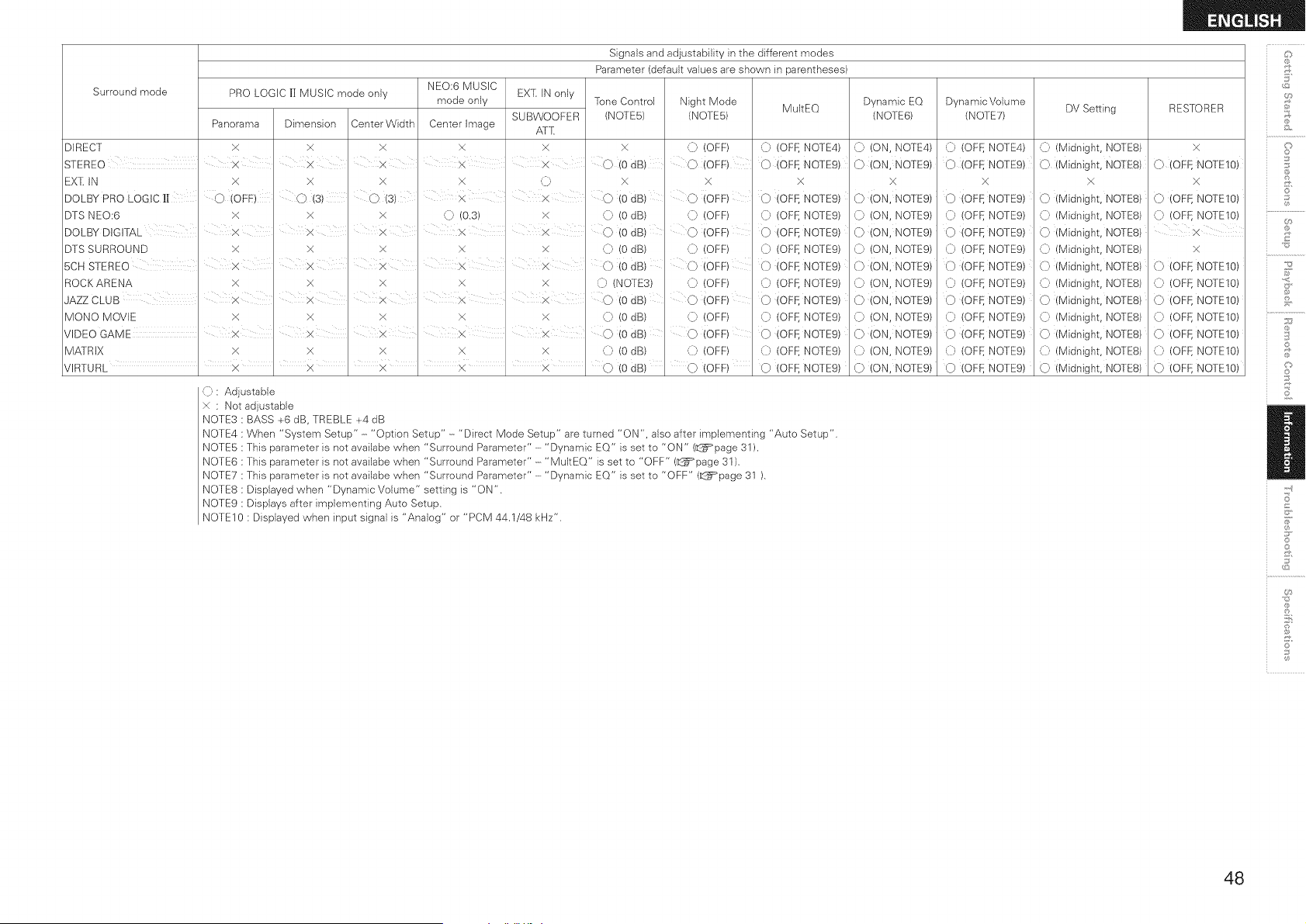
Signals and adjustability in the different modes _:?_
Parameter (default values are shown in parentheses)
Surround mode
PRO LOGIC |[ MUSIC mode only
Panorama Dimension Center Width
x >( X
NEO:6 MUSIC
mode only
Center Image
xDIRECT
I I
STEREO X X X X
EXT, IN only
SUBWOOFER
Afl[
X
X
Tone Control
(NOTES)
}<
0 (OdB)
Night Mode
MultEQ
(NOTES)
0 (OFF) {} (OFF, NOTE4)
0 (OFF)0 (OEE NOTEg)
Dynamic EQ
(NOTE@
,{} (ON, NOTE4)
0 (ON, NOTE9)
Dynamic Volume
(NOTE7)
([) (OFE NOTE4)
0 (OFF, NOTEg)
DV Setting
,{} (Midnight, NOTES)
0 (Midnight, NOTE8)
EX[: IN X × × X ,{} X
i I
DOLBY PRO LOGIC Ill 0 (OFE) 0(3) 0 (3) x x 0 (OdB)
DTS NEO:6 x x x 0 (0.3) × (_ (OdB)
I I I I I
DOLBY DIGITAL X X X X X 0 (OdB)
DTS SURROUND X X × X x
5CH STEREO X X X X ×
ROCKARENA X X X x x
I I I I
JAZZ CLUB X X X X X
MONO MOVIE X X x x X
VIDEO GAME _ X X X
MA]RIX x x x X x
(]) (OdB)
O (0 dB)
0 (NOT E3)
0 (OdB)
(]) (o dB)
(0 dB)
(} (0 dB)
:X
0 (OFF)
0 (OFF)
0 (OFF)
0 (OFF)
0 (OFF)
([) (OFF)
O (OFF)
(]) (OFF)
0 (OFF)
(D (OFF)
(OFF)
, , , , , , ,
VIRTURL X × ' X ' × ' X (J) (0 dB) (J)
>(
¢) (OFF, NOTE9)
{} (OFF, NOTE9)
(} (OFF, NOTE9)
(} (OFF, NOTE9)
0 (OFF, NOTE9)
(} (OFf:, NOTE9)
0 (OFF, NOTE9)
(} (OFF, NOTE9)
0 (OFF, NOTE9)
0 (OFI. NOTE9)
0 (OFF, NOTE9)
x
0 (ON, NOTE9)
0 (ON, NOTE9)
0 (ON, NOTE9)
0 (ON, NOTE9)
0 (ON, NOTE9)
0 (ON, NOTE9)
0 (ON, NOTE9)
0 (ON, NOTE9)
0 (ON, NOTE9)
0 (ON, NOTE9)
0 (ON, NOTE9)
x
0 (OFF, NOTE9)
0 (OFt. NOTE9)
0 (OFF, NOTE9)
(_. (OFt. NOTE9)
0 (OFF, NOTE9)
(_. (OFf_ NOTE9)
0 (OFF, NOTE9)
C (OFt. NOTE9)
O (OFF, NOTEg)
0 (OFf. NOTE9)
0 (OFF, NOTE9)
}<
0 (Midnight, NOTE8)
0 (Midnight, NOIE8)
0 (Midnight, NOTE8)
0 (Midnight, NOIE8)
0 (Midnight, NOTES)
0 (Midnight, NOqE8)
0 (Midnight, NO]ES)
0 (Midnight, NOqE8)
0 (Midnight, NOTES)
0 (Midnight, NOqE8)
0 (Midnight, NOTE8)
(): Adjustable
x : Not adjustable
NOTE3 : BASS +6 dB, TREBLE +4 dB
NOTE4 : When "System Setup" - "Option Setup" - "Direct Mode Setup" are turned "ON", also after implementing "Auto Setup".
NOTE5 : This parameter }s not ava}labe when "Surround Parameter" - "Dynamic EQ" is set to "ON" (_:@=_page31 ),
NOTE6 : This parameter is not availabe when "Surround Parameter" - "MultEQ" is set to "OFF" (_:_page 31 ).
NOTE7 : This parameter is not availabe when "Surround Parameter" - "Dynamic EQ" is set to "OFF" (_:_page 31 ).
NOTES : Displayed when "Dynamic Volume" setting is "ON".
NOTE9 : Displays after implementing Auto Setup.
NOTElO : Displayed when input signal is "Analog" or "PCM 44,1/48 kHz",
RESTORER
X
0 (QEF, NOTEIO)
X
0 (OFF, HOTELS)
([) (OFf:, NOTEIO)
x
0 (OFF, NOTEIO)
0 (OFf:, NOTEIO)
0 (OFF, NOTEIO)
0 (OFF, NOTEIO)
0 (OFF, NOTEIO)
0 (OFI. NOTEIO)
0 (OFF, NOTE1O)
@
©
3
©
S
S
Ii
S
©
48
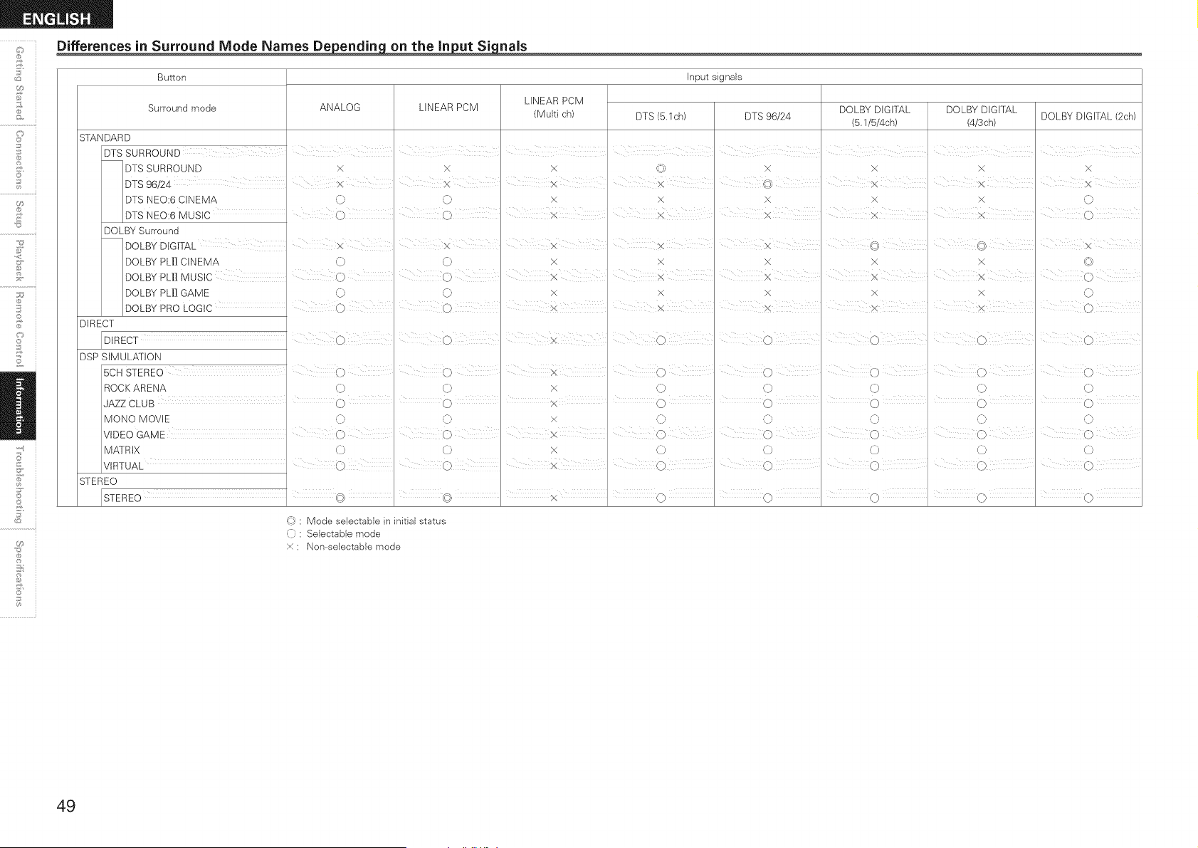
Differences in Surround Mode Names De_ on the In_nals
Button Input signals
LINEAR PCM
Surround mode ANALOG LINEAR PCM
(Multi ch) DTS (5.1ch) DTS 96/24
SIANDARD
DTS SURROUND
DTS SURROUND X X X _ x
DOLBY DIGrrAL DOLBY DIGrIAL
DOLBY DIGITAL (2ch)
(5.1/5/4ch) (4/3ch)
x x x
DTS 96/24 I x "" ' ' "" ' cb:..... _.. ,,j x x X
DTS NEO:6 CINEMA (} 0 x X X x x 0
i j
DTS NEO:6 MUSIC ..... 0 0 I X i X X X ,}
DOLBY Surround
DOLBY DIGIrAL i X x , x X _? I I X
DOLBY PL[] CINEMA 0 '0 X X X X X (<3
DOLBY PLII MUS C , O O x R × × × _ O
DOLBY PLII GAME 0 0 X x X X X 0
DOLBY PRO LOGIC 0 i 0 X X i X I X I 0
DIRECT
DIRECT I 0 I 0 I 0 I 0 I 0 I 0 I 0
DSP SIMULATION
BCH STEREO (} i i ,
R0 C K A REN A ,{}, (} X (} (} (} (} (}
JAZZ CLUB I ,O I ,O I X ,O I ,O I ,O I ,O I ,O
MO NO M OVl E '(]_ '(]_ × '(]_ '(]_ '(]_ '(]_ ']_
VIDEO GAME I 0 I 0 I X 0 I 0 I 0
M A] RiX 0 0 X 0 0 0 0 0
VIRTUAL , 0 ' 0' 0
STEREO
U9
11;
_): Mode selectabJe in initial status
(]): Selectable mode
× ; Non--selectable mode
49
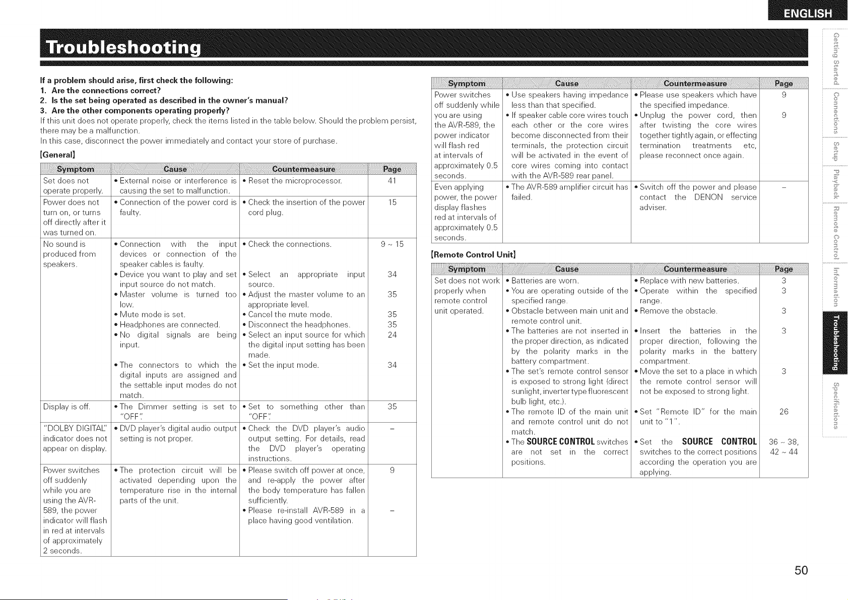
if a problem should arise, first check the following:
1. Are the connections correct?
2. is the set being operated as described in the owner's manual?
3. Are the other components operating properly?
If this unit does not operate properly, check the items listed in the table below. Should the problem persist,
there may be a malfunction.
In this case, disconnect the power immediately and contact your store of purchase.
[General]
o External noise or interference is o Reset the microprocessor. 41
causing the set to malfunction.
* Connection of the power cord is * Check the insertion of the power 15
faulty, cord plug.
* Check the connections. 9 ~ 15
Set does not
operate properly.
Power does not
turn on, or turns
off directly after it
was turned on.
No sound is
produced from
speakers.
oConnection with the input
devices or connection of the
speaker cables is faulty.
o Device you want to play and set
input source do not match.
oMaster volume is turned too
low.
o Mute mode is set.
o Headphones are connected.
o No digital signals are being
input.
oSelect an appropriate input
source.
* Adjust the master volume to an
appropriate level.
* Cancel the mute mode.
* Disconnect the headphones.
* Select an input source for which
the digital input setting has been
made.
* Set the input mode.
34
35
35
35
24
o The connectors to which the
digital inputs are assigned and
the settable input modes do not
match.
o The Dimmer setting is set to
"OFF'.'
o DVD player's digital audio output
setting is not proper.
34
Display is off. 35
"DOLBY DIGITAL'
indicator does not
appear on display.
9
o Set to something other than
"OFF"
o Check the DVD player's audio
output setting. For details, read
the DVD player's operating
instructions.
o Please switch off power at once,
and re-apply the power after
the body temperature has fallen
sufficiently.
o Please re-install AVR-589 in a
place having good ventilation.
o The protection circuit will be
activated depending upon the
temperature rise in the internal
parts of the unit.
Power switches
off suddenly
while you are
using the AVR-
589, the power
indicator will flash
in red at intervals
of approximately
2 seconds.
_J_!_!_!_!_!_!!}!!i_!i_!!_;;_!_!_!_i_!_i_!_i_!_!_!_!i!i!i!i!i!i!i!i!i!i!i!i!i!i!i_!_!_i_i_i_!:!_!_i_ii_ii_ii_ii_ii_ii_i!i!_i_i!_ii_ii_ii_i!i_i_i_i_i_i_i_i_i_i_i_i_i_i_i_iiii_i_i_i_i_!_!i!i!i!ii!ii!ii!iiiiiiiiiiiiiiiii_iiiiiiiiiiiiiiiiiiiiiiiiii_ii_iiii_i_i_i_;_i_i_!_!_!_!_!_!_!_!_!_!_!_i_i!!!!_i!_i_i_i_i_i_i_i_i_i_i_i_i_i_i_i_i_i_i_i_i_i_i_ii_ii_iiiiiiiiii!i!!_!_i!!i!!i!_i_!i_!i_!i_i_iii!_!_i_i!i_i_i_i_i_i_ii_ii_ii_ii_ii_ii_ii_ii_ii_ii_i_i_i!
Power switches
off suddenly while
you are using
the AVR-589, the
sower indicator
will flash red
at intervals of
approximately 0.5
seconds.
Even applying
power, the power
display flashes
red at intervals of
approximately 0.5
seconds.
o Use speakers having impedance
less than that specified.
o If speaker cable core wires touch
each other or the core wires
become disconnected from their
terminals, the protection circuit
will be activated in the event of
core wires coming into contact
with the AVR-589 rear panel.
The AVR-589 amplifier circuit has
failed.
Please use speakers which have 9
the specified impedance.
o Unplug the power cord, then 9
after twisting the core wires
together tightly again, or effecting
termination treatments etc,
please reconnect once again.
Switch off the power and please
contact the DENON service
adviser.
Remote Control Unit]
Set does not work
properly when
remote control
unit operated.
Batteries are worn.
You are operating outside of the
specified range.
Obstacle between main unit and
remote control unit.
The batteries are not inserted in
the proper direction, as indicated
by the polarity marks in the
battery compartment.
The set's remote control sensor
is exposed to strong light (direct
sunlight, inverter type fluorescent
bulb light, etc.).
The remote ID of the main unit
and remote control unit do not
match.
The SOURCE CONTROL switches
are not set in the correct
positions.
_!_!_i_ii_ii_ii_ii_Siiiiii_ii_ii_iii_ii_i_iiiiiiiiiiiiiiiiiiiiiiiiiiii_i_iii_i_!!!!_i_i!ii_ii_iiii!_!!_i_i_i_!_i_!_!!_i_i_i_i_i_i_i_!__!_!!i_!!_!!_!!_!!_!!_!!_!!_!!_!!_!!_!!_!!_!!_!!_!!_!!_!!_!!_!!_!!_!!_!!_!!_!_i!_!
Replace with new batteries.
Operate within the specified
range.
Remove the obstacle.
Insert the batteries in the
proper direction, following the
polarity marks in the battery
compartment.
Move the set to a place in which
the remote control sensor will
not be exposed to strong light.
=Set "Remote ID" for the main
unit to "1 ".
oSet the SOURCECONTROL
switches to the correct positions
according the operation you are
applying.
3
3
3
3
26
36 ~ 38,
42 ~ 44
©
©
£
S
©
50
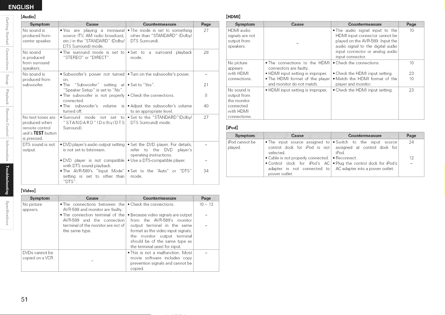
[Audio]
No sound is
produced from
center speaker.
No sound
is produced
from surround
speakers.
No sound is
produced from
subwoofer.
No test tones are
produced when
remote control
unit's TEST button
is pressed.
DTS sound is not
output.
*You are playing a monaural
source (TV, AM radio broadcast,
etc.) in the "STANDARD" (Dolby/
DTS Surround) mode.
*The surround mode is set to
"STEREO" or "DIRECT".
* Subwoofer's power not turned
on.
*The "Subwoofer" setting at
"Speaker Setup" is set to "No".
*The subwoofer is not properly
connected.
*The subwoofer's volume is
turned off.
*Surround mode not set to
"STANDARD" (Dolby/DTS
Surround).
* DVD player's audio output setting
is not set to bitstream.
* DVD player is not compatible
with DTS sound playback.
*The AVR-589's "Input Mode"
setting is set to other than
"DTS".
*The mode is set to something
other than "STANDARD" (Dolby/
DTS Surround).
*Set to a surround playback
mode.
* Turn on the subwoofer's power.
* Set to "Yes".
* Check the connections.
*Adjust the subwoofer's volume
to an appropriate level.
* Set to the "STANDARD'(Dolby/
DTS Surround) mode.
* Set the DVD player. For details,
refer to the DVD player's
operating instructions.
* Use a DTS-compatible player.
*Set to the "Auto" or "DTS"
mode.
27
28
21
9
4O
27
34
[Video]
No picture *The connections between the * Check the connections. 10~ 13
appears.
DVDs cannot be
copied on aVCR.
AVR-589 and monitor are faulty.
*The connection terminal of the
AVR-589 and the connection
terminal of the monitor are not of
the same type.
* Because video signals are output
from the AVR-589's monitor
output terminal in the same
format as the video input signals,
the monitor output terminal
should be of the same type as
the terminal used for input.
*This is not a malfunction. Most
movie software includes copy
prevention signals and cannot be
copied.
HDMI audio
signals are not
output from
speakers.
No picture
appears
with HDMI
connections.
No sound is
output from
the monitor
connected
with HDMI
connections.
*The connections to the HDMI
connectors are faulty.
* HDMI input setting is improper.
*The HDMI format of the player
and monitor do not match.
* HDMI input setting is improper.
*The audio signal input to the
HDMI input connector cannot be
played on the AVR-S89. Input the
audio signal to the digital audio
input connector or analog audio
input connector.
* Check the connections.
* Check the HDMI input setting.
* Match the HDMI format of the
player and monitor.
* Check the HDMI input setting.
10
10
23
10
23
[iPod]
iPod cannot be
played.
*The input source assigned to
control dock for iPod is not
selected.
o Cable is not properly connected.
* Control dock for iPod's AC
adapter is not connected to
power outlet.
*Switch to the input source
assigned at control dock for
iPod.
o Reconnect.
* Plug the control dock for iPod's
AC adapter into a power outlet.
24
12
51
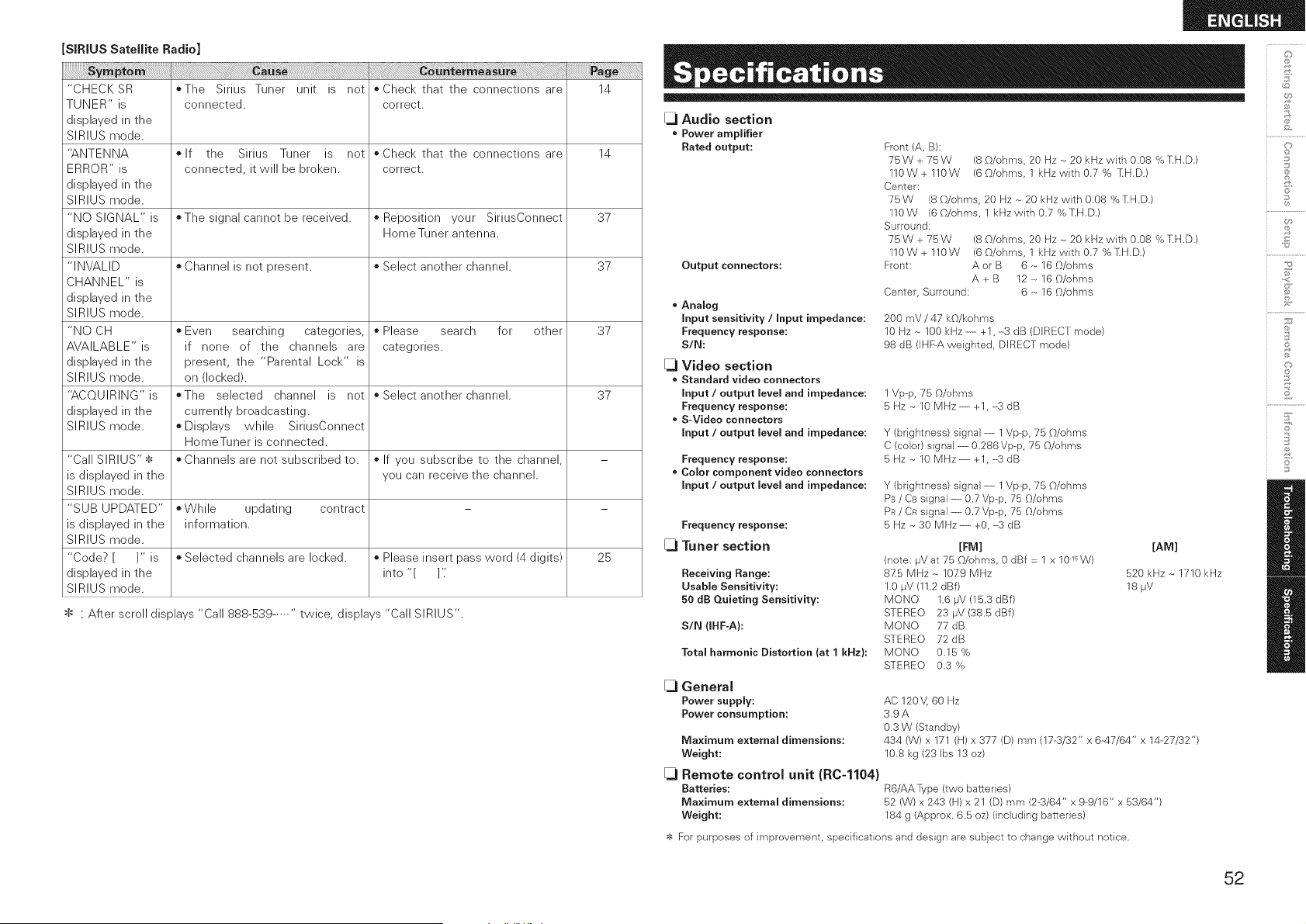
SiRiUS Satellite Radio]
"CHECKSR ©The Sirius Tuner unit is not ©Check that the connections are 14
TUNER" is connected, correct.
displayed in the
SIRIUS mode.
"ANTENNA ©If the Sirius Tuner is not ©Check that the connections are 14
ERROR" is connected, it will be broken, correct.
displayed in the
SIRIUS mode.
"NO SIGNAL" is ©The signal cannot be received, o Reposition your SiriusConnect 37
displayed in the HomeTuner antenna.
SIRIUS mode.
"INVALID o Channel is not present, o Select another channel. 37
CHANNEL" is
displayed in the
SIRIUS mode.
"NO CH o Even searching categories, o Please search for other 37
AVAILABLE" is if none of the channels are categories.
displayed in the present, the "Parental Lock" is
SIRIUS mode. on (locked).
"ACQUIRING"is ©The selected channel is not o Select another channel. 37
displayed in the currently broadcasting.
SIRIUS mode. *Displays while SiriusConnect
HomeTuner is connected.
"Call SIRIUS"$ o Channels are not subscribed to. ©If you subscribe to the channel, -
is displayed in the you can receive the channel.
SIRIUS mode.
"SUB UPDATED" *While updating contract - -
is displayed in the information.
SIRIUS mode.
"Code? [ ]" is _ Selected channels are locked, o Please insert pass word (4 digits) 25
displayed in the into "[ ]'_
SIRIUS mode.
$ : After scroll displays "Call 888-539 ..... " twice, displays "Call SIRIUS".
[_ Audio section
• Power amplifier
Rated output:
Output connectors:
• Analog
Input sensitivity / Input impedance:
Frequency response:
S/N:
[_ Video section
• Standard video connectors
Input / output level and impedance:
Frequency response:
• S-Video connectors
Input / output level and impedance:
Frequency response:
• Color component video connectors
Input / output level and impedance:
Frequency response:
[_ Tuner section
Receiving Range:
Usable Sensitivity:
50 dB Quieting Sensitivity:
SIN (IHF-A):
Total harmonic Distortion (at 1 kHz):
[_ General
Power supply:
Power consumption:
Maximum external dimensions:
Weight:
[_ Remote control unit (R0-1104}
Batteries:
Maximum external dimensions:
Weight:
Front (A, B):
75W+75W (8 O/ohms, 20 Hz ~ 20 kHz with 0.08 % ],H,D,)
110W+110W (60/ohms, 1 kHzw}thO,7% 'IIH,D.)
Center:
75W (8 _b/ohms, 20 Hz ~ 20 kHz with 0.08 % IIH.D.)
1lOW (6_b/ohms, 1 kHzw}thO.7%],H,D,)
Surround:
75W+75W (8 O/ohms, 20 Hz ~ 20 kHz with 0.08 % ],H,D,)
110W + 110W (6 O/ohms, 1 kHz w}th 0,7 % IIH.D.)
Front: A or B 6 ~ 16 O/ohms
A + B 12 ~ 16 O/ohms
Center, Surround: 6 ~ 16 O/ohms
200 mV / 47 kO/kohms
10 Hz ~ 100 kHz ---------+1, -3 dB (DIRECT mode)
98 dB (IHF-A weighted, DIRECT mode)
1 Vp-p, 75 O/ohms
5 Hz ~ 10 MHz ---------+1, -3 dB
Y (brightness) signal-- 1Vp-p, 75 _b/ohms
C (color) signal---------0,286Vp--p, 75 O/ohms
5 Hz ~ 10 MHz ---------+1, ----3dB
Y (brightness) signal---------1Vp-p, 75 {)/ohms
PB / Cs signal---------0,7 Vp@, 75 O/ohms
PR/ CR signal---------0,7 Vp--p, 75 O/ohms
5 Hz ~ 30 MHz ---------+O, -3 dB
[FM]
(note: l_V at 75 O/ohms, 0 dBf = 1 x 101_W)
8Z5 MHz ~ 10-Z9 MHz
1.0 IJV (11.2 dBf)
MONO 1.6 IJV (15,3 dBf)
STEREO 23 #V (38.5 dBf)
MONO 77 dB
STEREO 72dB
MONO 0.15 %
STEREO 0.3 %
[AM]
520 kHz ~ 1710 kHz
18 ,uV
AC 120V, 60 Hz
3.9A
0.3 W (Standby)
434 (W) x 171 (H) x 377 (D) mm (17-3/32" x 6.-47/64" x 14.27/32")
10,8 kg (23 Ibs 13 oz)
R6/AAType (two batteries)
52 (W) x 243 (H) x 21 (D) mm (2.3/64" x 9@/16" x 53/64")
184 g (Approx. 6,5 oz) (}nclud}ng batter}es)
$ For purposes of }mprovement, specifications and des}gn are subject to change without notice.
©
&
©
£
S
Z
©
©
52
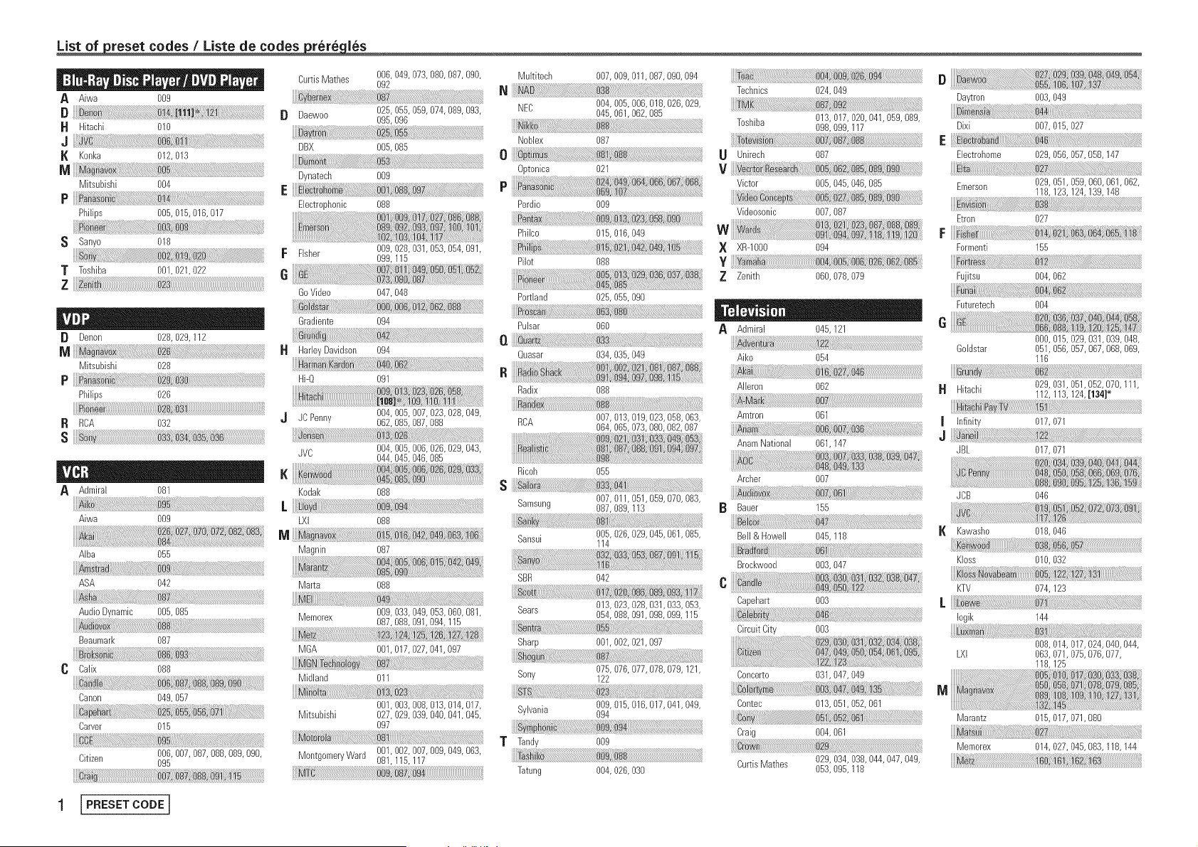
_reset codes / Liste de codes _les
A Aiwa 009
B
H Hitachi 010
J
I{ Konka 012, 013
M
Mitsubishi 004
P
Philips 005, 015,016, 017
S Sanyo 018
T Toshiba 001,021,022
z
[} Denon 028, 029, 112
M
Mitsubishi 028
P
Philips 026
R RCA 032
s
A Admiral 081
i :
Aiwa 009
AJba 055
ASA 042
Audio Dynamic 005, 085
Beaumark 087
C Calix 088
Canon 049, 057
Carver 015
Citizen 006, 007,087, 088,089, 090,
095
CurtisMathes 006, 049, 073,080, 087,090,
092
[} Daewoo 025, 055, 059,074, 089,093,
095, 096
yo :
DBX 005, 085
_.mo:::::
Dynatecb 009
E
Electrophonic 088
F Fisher 009, 028, 031,053, 054,091,
099, 115
G
GoVideo 047,048
ate:
Gradiente 094
HarleyDavidson 094
Hi-Q 091
JC Penny 004, 005, 007,023, 028,049,
062, 085,087, 088
JVC 004, 005, 006,026, 029,043,
044, 045,046, 085
K _-,enwo_ ..........................
DS_ , ......................................................
Kodak 088
LXI 088
M
Magnin 087
Marta 088
Memorex 009, 033, 049,053, 060,081,
087,088, 091,094, 115
MGA 001,017,027, 041,097
Midland 011
001,003, 008,013, 014,017,
Mitsubishi 027,029, 039,040, 041,045,
O97
MontgomeryWard 001,002, 007,009, 049,063,
081,115, 117
1 I PRESETCODE J
Multitech 007,009, 011,087,090, 094
N
NEC 004,005, 006,018, 026,029,
045,061,062, 085
Noblex 087
o
Optonica 021
Perdio 009
Philco 015,016, 049
Pilot 088
s
Portland 025,055, 090
Pulsar 060
I1
Quasar 034,035, 049
R
Radix 088
RCA 007,013, 019,023, 058,063,
064,065, 073,080,082, 087
Ricoh 055
S
Samsung 007,011,051,059, 070,083,
087,089,113
Sansui 005,026, 029,045,061,085,
114
SBR 042
ot i !
Sears 013,023, 028,031,033, 053,
054,088, 091,098,099, 115
Sharp 001,002, 021,097
...... n _ :::
Sony 075,076, 077,078, 079, 121,
122
Sybania 009,015, 016,017,041,049,
094
T Tandi 00_
Ta ......
Tatung 004,026, 03()
Technics 024,049
Toshiba 013, 017,020, 041,059, 089,
098,099, 117
Unirech 087
v _ ::_
Victor 005,045, 046,085
Videosonic 007,087
X XR-IO00 O94
Y
Z Zenith 060,078, 079
A Admiral 045, 121
dv
Aiko 054
Aileron 062
Amtron 061
AnamNational 061,147
Archer 007
Bauer 155
Bell & Howell 045,118
Brockwood 003,047
_3
C
Capehart 003
Circuit City 003
Concerto 031,047,049
Contec 013,051,052,061
Craig 004,061
CurtisMatbes 029,034,038,044,047, 049,
053,095,118
D
Daytron 003, 049
Dixi 007, 015, 027
E
Ebctrohome 029, 056,057,058, 147
i
Emerson 029, 051,059, 060,061,062,
118, 123,124, 139,148
Etron 027
F
Formenti 155
Fujitsu 004, 062
Futuretech 004
e
000, 015,029, 031,039, 048,
Goldstar 051,056, 057,067,068, 069,
116
H Hitachi 029, 031,051,052, O7O,111,
112, 113,124,[134]*
v
I Infinity 017, 071
J
JBL 017, 071
JCB 046
K Kawasho 018, 046
Kloss 010,032
KTV 074,123
Iogik 144
008,014,017,024,040,044,
LXI 063,071,075,076,077,
118,125
M
Marantz 015, 017,071,080
Memorex 014, 027,045,083, 118, 144
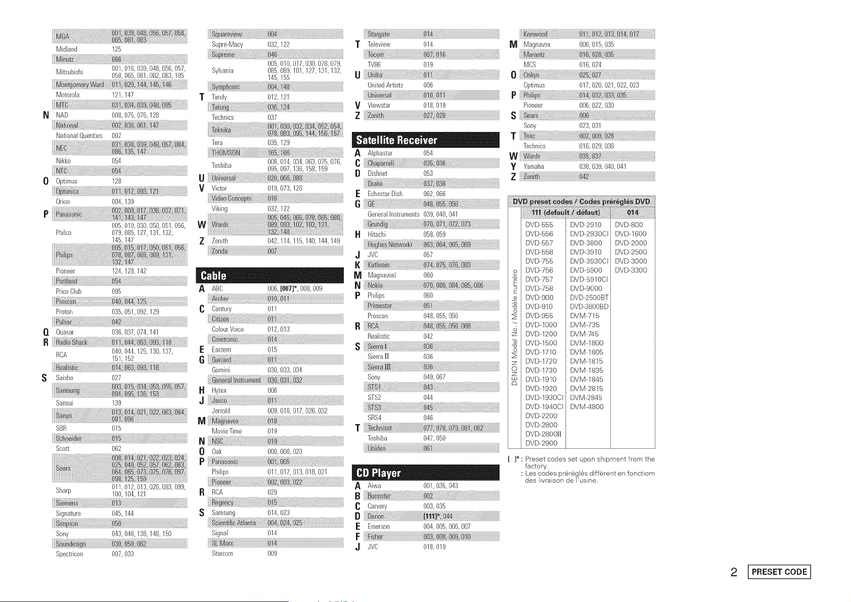
Midland 125
Mitsubishi 001,016,039,048,056,057,
058,065,081,082,083,105
Motorola 121,147
M
NAD 008, 075,076, 128
.! !
National Quenties 002
Nikko 054
0 0ptimus 128
Orion 004, 139
P
005, 010,030, 050,051,056,
Philco 079, 085, 127,131,132,
145,147
Pioneer 124,128,142
......Bi!i_i_iiiiiiiJ_!_!_i_!iii:i_i_:!_:!i_!!!!_!_!!_!_!_!!!!!_!_!_ii_i_i_i_i_i_i_@_ii_iiii_!i_ii_i__i_i_!i!i!i_i!!i!_i_!_!_i!_i!_i_i_!!_!_!!_i_i!_!!i_!i!i!i_!!_!_!!!iiiiiiiiiiiiiii_!_!_!!_i_i!i!!i_!i!i!i_!!_!_!!!iiiiiiiiiiiiiii_!_!:!!_i_i!i!!i_!i!i!i_!!_!_!!!iiiiii_ii_i_
PriceClub 095
Proton 035,051,092,129
O. Quasar 036,037,074,141
Ri
RCA 040,044,125,130,137,
151,152
S Saisho 027
Sansui 139
SBR 015
Scott 062
Sharp 011,012, 013, 028,093, 099,
100,104, 121
m:
Signature 045, 144
im
Sony 043, 046, 138,146, 150
Spectricon 007, 033
T
Supre-Macy 032, 122
005,010,017,030,078,079,
Sylvania 085, 089, 101,127, 131,132,
145,155
Tan@ 012, 121
Technics 037
Tera 035, 129
Toshiba 008, 014,034, 063,075, 076,
095, 097,136, 158, 159
U
V Victor 019,073, 126
Viking 032, 122
Z Zenith 042, 114, 115,140, 144,149
ABC 006, [007]*, 008,009
Century 011
CeiourVoice 012, 013
E Eastern 015
6
Gemini 030, 033,034
H Hytex 008
J
Jerrold 009, 016,017, 026,032
Movie Time 019
N
0 Oak 000,006,020
P
Philips 011,012, 013, 018,021
ROA O29
S Samsung 014,023
Signal 014
Starcom 0(}9
ta_ t_ :
T Teleview 014
TV86 019
UnitedArtists 006
V Viewstar 018,019
z
A Alphastar 054
[} Dishnet 053
E EcbostarDish 062,066
G
GeneralInstruments 039,040, 041
Hitachi 058,059
.J JVC 067
I{
Magnavoxl 060
p Phi@s 060
Prescan 048,055, 088
B
Realistic 042
s
Sierra|J 036
Sony 049,067
STS2 044
SRS4 046
T
Toshiba 047,050
A Aiwa 001,035, 043
Carvery 003,035
B
E Emeison 004100Sl006O07
F
,J JVC 018,019
Magnavox 006,015, 035
MCS 016,024
o
0ptimus 017,020, 021,022, 023
P
Pioneer 006,022, 030
s
Sony 023,031
T
Technics 016,029, 036
W :7
y Yamaha 038,039,040, 041
z
o
o
z
o
DVD-555
DVD-556
DVD-557
DVD-558
DVD-755
DVD-756
DVD-757
DVD-758
DVD-900
DVD-910
DVD-955
DVD-IO00
DVD-1200
DVD-1500
DVD-1710
DVD-1720
DVD-1730
DVD-1910
DVD-1920
DVD-1930CI
DVD-1940CI
DVD-2200
DVD-2800
DVD-280011
DVD-2900
i DVD--2910
i DVD--2930CI
i DVD--3800
_ DVD--3910
i DVD--3930CI
i DVD--5900
i DVD--5910CI
i DVD-9000
_ DVD-2500BT
i DVD-3800BD
i DVM--715
i DVM--735
i DVM:74 5
i DVM-1800
i DVM-1805
i DVM-1815
i DVM--1835
i DVM--1845
i DVM--2815
i DVM-2845
i DVM--4800
DVD-800
DVD-1600
DVD-2000
DVD-2500
DVD-3000
DVD-3300
[ ]* : Preset codes set upon shipment from the
factory.
: Les codes prer#;gles diff@ent en fonctiom
des livraison de Fusine.
2 [PRESETCODE]

DENON
www.denon.com
Denon Brand Company, D&M Hold}ngs inc.
Pr}nted }n Ch}na 5411 10042 O06D