CD67G0C2CJ/UKCD67G0C2CJ/UKCD67G0C2CJ/UK

EN
ENGLISH
Health and Safety guide
Installation guide
Quick guide
2
3
EN
SAFETY INSTRUCTIONS
IMPORTANT TO BE READ AND OBSERVED
CAUTION : Use of the gas cooking appliance
results in the production of heat, moisture and
products of combustion in the room in which
it is installed. Ensure that the kitchen is well
ventilated, especially when the appliance is in
use: keep natural ventilation holes open or
install a mechanical ventilation device (mechanical
extractor hood). Prolonged intensive use of the
appliance may call for additional ventilation, such
as openingawindow, or more effectiveventilation,
for example increasing the level of mechanical
ventilation (if possible).
Failure to follow the information in this manual exactly may cause a
fire or explosion, resulting in property damage or personal injury.
Before using the appliance, read these safety
instructions. Keep them nearby for future
reference.
These instructions and the appliance itself provide
important safety warnings, to be observed at all
times. The manufacturer declines any liability for
failure to observe these safety instructions, for
inappropriate use of the appliance or incorrect
setting of controls.
WARNING: The appliance and its accessible
parts become hot during use. Care should
to avoid touching heating elements. Children less
than 8 years of age must be kept away unless
continuously supervised.
WARNING : Danger of fire : Do not store items
on the cooking surfaces.
CAUTION : The cooking process has to be
supervised. A short cooking process has to be
supervised continuously.
WARNING: Leaving the hob unattended when
cooking with fat or oil can be dangerous – risk of
fire. NEVER try to extinguish a fire with water, but
switch off the appliance and then cover the flames
e.g. with a lid or a fire blanket.
Do not use the hob as a work surface or support.
Keep clothes or other flammable materials away
from the appliance, unitl all the components have
cooled down completely - risk of fire.
Very young children (0-3 years) should be kept
away from the appliance. Young children (3-8
years) should be kept away from the appliance
unless continuously supervised. Children from 8
years old and above and persons with reduced
physical, sensory or mental capabilities or lack of
experience and knowledge can use this appliance
only if they are supervised or have been given
instructions on safe use and understand the
hazards involved. Children must not play with the
appliance. Cleaning and user maintenance must
not be carried out by children without supervision.
CAUTION : In case of hotplate glass breakage:-
shut immediately off all burners and any electrical
heating element and isolate the appliance from
the power supply; - do not touch the appliance
surface; -do not use the appliance
The glass lid can break
Turn off all
Do not shut
WARNING: The appliance and its accessible
parts become hot during use. Care should be taken
to avoid touching heating elements. Children less
than 8 years of age must be kept away unless
continuously supervised.
Never leave the appliance unattended during
use.
Keep clothes or other flammable materials
away from the appliance, until all the components
have cooled down completely - risk of fire. Always
be vigilant when cooking foods rich in fat, oil or
when adding alcoholic beverages - risk of fire. Use
oven gloves to remove pans and accessories. At
the end of cooking, open the door with caution,
allowing hot air or steam to escape gradually
before accessing the cavity - risk of burns. Do not
obstruct hot air vents at the front of the oven - risk
of fire.
Exercise caution when the oven door is in the
open or down position, to avoid hitting the door.
When you place the rack inside, make sure that
the stop is directed upwards and in the back of the
cavity.
and open the compartment door and/or
wait at least 1 min before attempting a further
ignition of the burner.
PERMITTED USE
CAUTION: The appliance is not intended to
be operated by means of an external switching
device, such as a timer, or separate remote
controlled system.
This appliance is intended to be used in
household and similar applications such as: staff
kitchen areas in shops, offices and other working
environments; farm houses; by clients in hotels,
be taken
if it is heated.
burners before closing the lid.
the lid when burners are lit.
The ignition device shall not be operated for
more than 15 seconds. If after 15 seconds
the burner has not lit, stop operating the device
motels, bed & breakfast and other residential
environments.
No other use is permitted (e.g. heating rooms).
This appliance is not for professional use. Do
not use the appliance outdoors.
Do not store explosive or flammable
substances (e.g. gasoline or aerosol cans) inside or
near the appliance - risk of fire.
Use pots and pans with bottoms the same
width as that of the burners or slightly larger (see
Improper use of the grids can result in damage
to the hob: do not position the grids upside down
or slide them across the hob.
Do not let the burner flame extend beyond the
edge of the pan
Do not use : Cast iron griddles, ollar stones,
terracotta pots and pans. Heat diffusers such as
metal mesh, or any other types. Two burners
simultaneously for one receptacle (e.g. Fish
kettle).
Should particular local conditions of the delivered
gas make the ignition of burner difficult, it is
advisable to repeat the operation with the knob
turned to small flame setting.
In case of installation of a hood above the cooktop,
please refer to the hood instructions for the correct
distance.
The protective rubber feet on the grids represent
a choking hazard for young children. After
removing the grids, please ensure that all the feet
are correctly fitted.
INSTALLATION
cuts.
The electrical and gas connections must
comply with local regulation.
Installation,
electrical connections and repairs must be carried
out by a qualified technician. Do not repair or
replace any part of the appliance unless specifically
stated in the user manual. Keep children away from
the installation site. After unpacking the appliance,
make sure that it has not been damaged during
transport. In the event of problems, contact the
dealer or your nearest Aftersales Service. Once
installed, packaging waste (plastic, styrofoam
parts etc.) must be stored out of reach of
children - risk of suffocation. The appliance must
be disconnected from the power supply before
any installation operation - risk of electric shock.
During installation, make sure the appliance does
not damage the power cable - risk of fire or electric
shock. Only activate the appliance when the
installation has been completed.
This means LPG cylinders, whether partially or
completely full, must not be installed or stored
in rooms or storage areas that are below ground
level (cellars, etc.). It is advisable to keep only the
cylinder being used in the room, positioned so
that it is not subject to heat produced by external
sources (ovens, fireplaces, stoves, etc. ) which
could raise the temperature of the cylinder above
50°C.
Should you find it difficult to turn the knobs for the burner, please
contact the After-sales Service, who can replace of the burner tap if
found to be faulty.
The openings use for the ventilation and dispersion of heat must never
be covered.
4
(in certain models only)
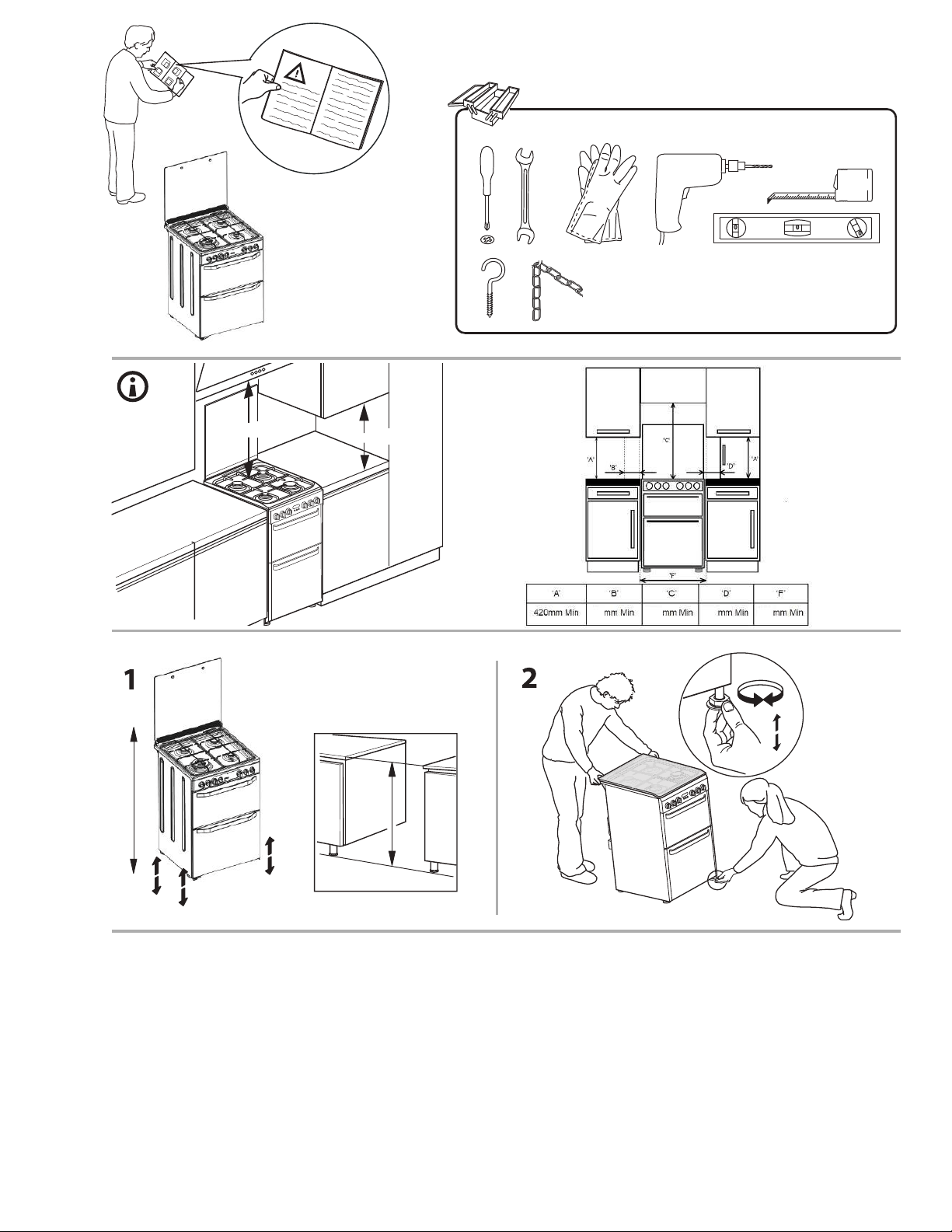
We recommend the appliance should be handled
and installed by two or more persons - risk of injury.
Use protective gloves to unpack and install - risk of
GAS CONNECTION
WARNING : Prior to installation, ensure that the
local distribution conditions (type of gas and gas
pressure) and the configuration of the appliance
are compatible.
Check that the pressure of the gas supply is
consistent with the values indicated in Table 1
(“Burner and nozzle specifications”).
WARNING : The configuration conditions of
this appliance are stated on the label (or data
plate).
WARNING : This appliance is not connected
to a combustion products evacuation device. It
must be installed and connected in accordance
with current installation regulations. Particular
attention must be paid to the relevant
requirements regarding ventilation.
If the appliance is connected to liquid gas,
the regulation screw must be
IMPORTANT : When the gas cylinder or gas
container is installed, it must be properly settled
(vertical orientation).
WARNING : This operation must be perfomed
by a qualified technician
adjusted to the
minimum setting.
The appliance shouldbe connectedtothemain
gas supply or to a gas cylinder in compliance with
the current national regulations. Before making
the connection, make sure that the appliance is
compatible with the gas supply you wish to use.
If it is not, follow the instructions indicated in the
paragraph "Adapting to different types of gas".
not protrude beyond the edge of the hob.
specific table). Make sure pots on the grates do
WARNING : Modification of the appliance and
its method of installation are essential in order to
use the appliance safely and correctly in all the
additional countries
Use pressure regulators suitable for the gas
pressure indicated in the instruction.
The room must be equipped with an air
extraction system that expels any combustion
fumes.
Liquid petroleum gas sinks to the floor as it
is heavier than air. Therefore, rooms containing
LPG cylinders must also be equipped with vents
to allow gas to escape in the event of a leak.
After connection to the gas supply, check for
leaks
minimum
position 2* to check flame stability.
Connection to the gas network or the gas
cylinder may be carryout using a flexible rubber
or steel hose, in accordance with current national
legislation.
in accordance with IGEM/UP/1B. Light up the
burners and turn the knobs from max position 1* to
5
ADAPTING TO DIFFERENT TYPES OF GAS
(This operation needs to be carried out by a
qualified technician.)
In order to adapt the appliance to a type of gas
other than the type for which it was manufactured
(indicatedontherating label), follow the dedicated
steps provided after installation drawings.
ELECTRICAL WARNINGS
IMPORTANT: Information about current and
voltage consumption is provided on the rating
plate.
The rating plate is on the front edge of the
oven (visible when the door is open).
It must be possible to disconnect the appliance
from the power supply by unplugging it if
plug is accessible, or by a multi-pole switch
installed upstream of the socket in accordance
with the wiring rules and the appliance must
be earthed in conformity with national electrical
safety standards.
The power cable must be long enough to connect the appliance,
once fitted in its housing, to the main power supply. Do not pull the
power supply cable.
Do not use extension leads, multiple sockets
or adapters. The electrical components must not
be accessible to the user after installation. Do not
use the appliance when you are wet or barefoot.
Do not operate this appliance if it has a damaged
power cable or plug, if it is not working properly,
or if it has been damaged or dropped.
If the supply cord is damaged, it must
be replaced with an identical one by the
manufacturer, its service agent or similarly
qualified persons in order to avoid a hazard -
risk of electric shock.
If the power cable needs to be replaced,
contact an authorised service centre.
CLEANING AND MAINTENANCE
WARNING: Ensure that the appliance is
switched off and disconnected from the power
supply before performing any maintenance
operation; never use steam cleaning equipment -
risk of electric shock.
Do not use harsh abrasive cleaners or metal
scrapers to clean the door glass since they can
scratch the surface, which may result in shattering
of the glass.
Do not use abrasive or corrosive products,
chlorine-based cleaners or pan scourers.
Make sure the appliance has cooled down
before cleaning or performing maintenance. - risk
of burns.
WARNING: Switch off the appliance before
replacing the lamp - risk of electric shock.
To avoid damaging the electric ignition device, do not use it when
the burners are not in their housing.
Wear protective gloves for cleaning and
maintenance.
DISPOSAL OF PACKAGING MATERIALS
The packaging material is 100% recyclable and is marked with the
recycle symbol . The various parts of the packaging must therefore
be disposed of responsibly and in full compliance with local authority
regulations governing waste disposal.
DISPOSAL OF HOUSEHOLD APPLIANCES
This appliance is manufactured with recyclable or reusable materials.
Dispose of it in accordance with local waste disposal regulations.
ENERGY SAVING TIPS
Only preheat the oven if specified in the cooking table or your recipe. Use
dark lacquered or enamelled baking trays as they absorb heat better.
Use a pressure cooker to save even more energy and time.
DECLARATION OF CONFORMITY
This appliance meets Ecodesign requirements of European Regulation
66/2014 in compliance with the European standard EN 60350-1.
This appliance meets Ecodesign requirements of European Regulation
66/2014 in compliance with the European standard EN 60350-2.
This appliance meets Ecodesign requirements of European Regulation
66/2014 in compliance with the European standard EN 30-2-1
This appliance meets Ecodesign requirements of European Regulation
65/2014 in compliance with the European standard EN 15181.
��� ������� ����������� �� ��� ���������� �������� ��� ���������
�� ��������� ���������� ����������� ������� ���� ����� ���������� ���
���������� ������� ��� ��������� ����� �� ��� ����� ����� ��� ���������
��� ���������� ���� ��������� �� ������ �� ���������� ���� ��������
��������� ����������� ����� ���������� ��� ���������� ��������� ������
�� �������� ���� ������� �� �������� �� ���������� ��� ���� ���� �������
�������� ������������ ��� ��� ����������� ��� ����� ������� ���
������
�� ��� ������� �� �� ��� ������������ �������������
��������� ���� �� ������ ��� �� ������� �� �������� ����� ��� ���� ��
����� �� �� ����������� ���������� ������ ��� ��� ��������� �� ����������
��� ���������� ����������
and with the Waste Electrical and Electronic Equipment regulations
2013 (as amended).

6
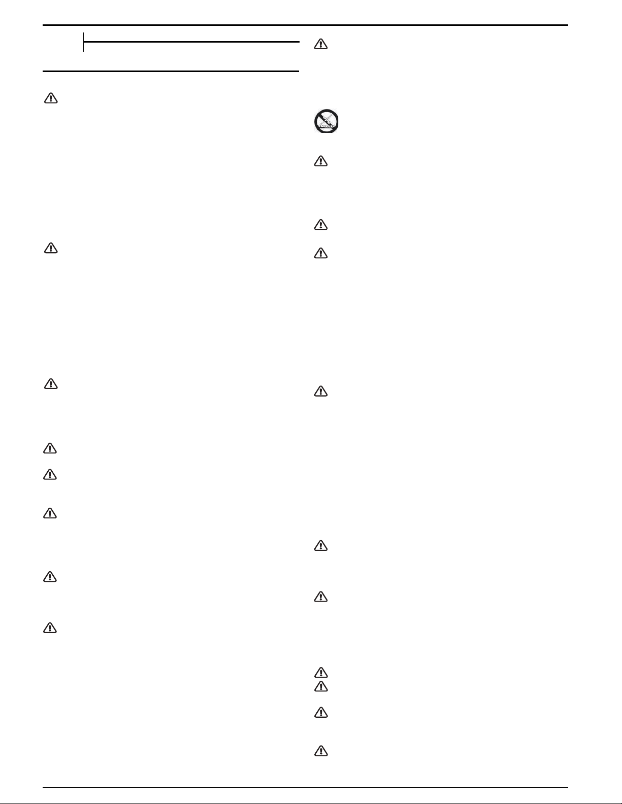
PRODUCT DESCRIPTION
7
EN
1.
Control panel
4. Runners for accessories
(the level is indicated on the wall
of the cooking compartment)
6.
Glass cover
1.
2.
2.
Main oven door
Removable Inner Door Glass
5.
5.
Gas burners
3.
3.
4.
6.
4.
Oven light
Timer
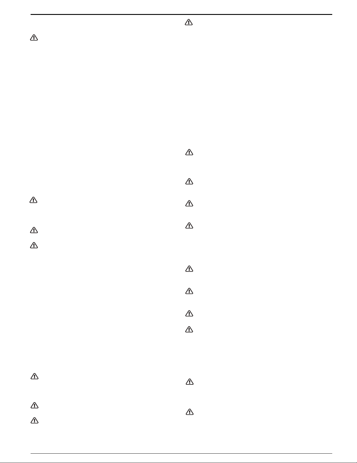
CONTROL PANEL
Left rear
hob burner
Left front
hob burner
Thermostat
Top oven
Main oven
Thermostat
Right front
hob burner
Right rear
hob burner
8
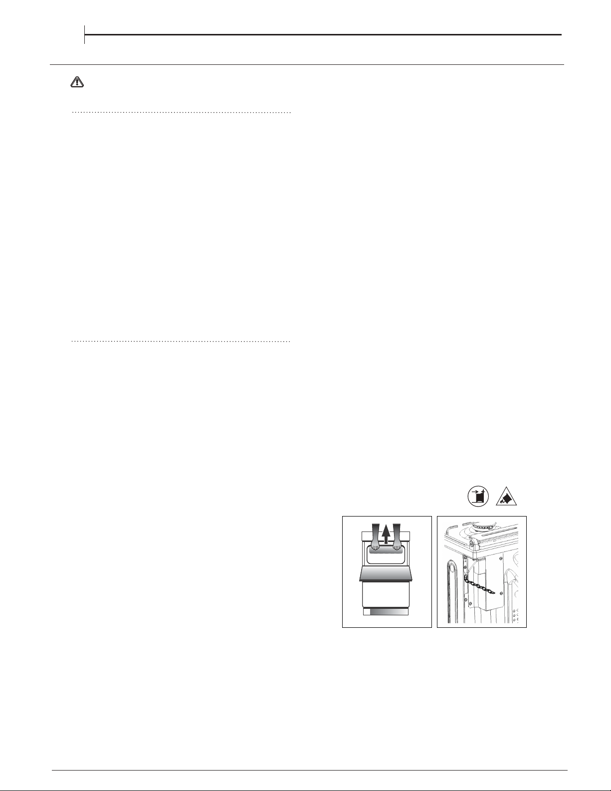
Before moving your cooker check that it is cool, and
switch off at the cooker control unit. Movement of
your cooker is most easily achieved by lifting the
front as follows:
Open the grill door sufficiently to allow a comfortable
grip on the underside front edge of the oven roof,
avoiding any grill elements. (FIG.A)
Take care in moving the cooker as it is heavy.
Take care to ensure that any floor covering is not
damaged.
Splashplate optional, apply to Parts Department
(see Back Cover for contact number.)
The following instructions should be read by a
qualified technician to ensure that the appliance is
installed, regulated and technically serviced
correctly in compliance with current regulations.
Positioning
Installation of the cooker
Moving the Cooker
Fig. A
INSTALLATION TIPS
EN
WARNING : This operation must be perfomed
by a qualified technician
This unit may be installed and used only in
permanently ventilated rooms according to the British
The following
a. The cooker should not be installed in a bed sitting
room with a volume of less than 20m
3
. If it is installed
in a room of volume less than 5m
3
an air vent of
effective area of 100cm
2
is required, if it is installed
in a room of volume between 5m
3
and 10m
3
a
supplementary airvent area of 50cm2 is required,
if the volume exceeds 10m
3
no airvent is required.
However, if the room has a door or a window which
opens directly to the outside no air vent is required
even when the volume is between 5m
3
and 10m
3
.
b. During prolonged use of the appliance you may
consider it necessary to open a window to the
outside to improve ventilation.
c. If there are other fuel burning appliances in the
same room, B.S.5440 Part 2 Current Edition, should,
be consulted to determine the requisite air vent.
The room containing the appliance must contain
an openable window or an acceptable alternative
such as an adjustable louvre or hinged panel
opening direct to outside air.
This unit may be installed and used only in
permanently ventilated rooms according to the British
Standards Codes Of Practice: BS 5440 Part 2
requirements must be observed:
a. The cooker should not be installed in a bed sitting
room with a volume of less than 20m
3
. If it is installed
in a room of volume less than 5m
3
an air vent of
effective area of 100cm
2
is required, if it is installed
in a room of volume between 5m
3
and 10m
3
a
supplementary airvent area of 50cm2 is required,
if the volume exceeds 10m
3
no airvent is required.
However, if the room has a door or a window which
opens directly to the outside no air vent is required
even when the volume is between 5m
3
and 10m
3
.
b. During prolonged use of the appliance you may
consider it necessary to open a window to the
outside to improve ventilation.
c. If there are other fuel burning appliances in the
same room, B.S.5440 Part 2 Current Edition, should,
be consulted to determine the requisite air vent.
The room containing the appliance must contain
an openable window or an acceptable alternative
such as an adjustable louvre or hinged panel
opening direct to outside air.
For a correct installation of the cooker the following
precautions must be followed:
The height of the cooker can be adjusted by means
Adjust the feet by tilting the cooker from the side.
Then install the product into position.
NOTE: This appliance must not be fitted on a
platform.
The cooker is designed to fit between kitchen
cabinets spaced 600mm apart. The space either
side need only be sufficient to allow withdrawal of
the cooker for servicing. It can be used with
cabinets one side or both as well as in a corner
setting. It can also be used free-standing.
Adjacent side walls which project above hob level,
65mm and should be protected by heat
resistant material. Any overhanging surface or
cooker hood should not be nearer than 750mm.
a )a )
a )a )
a ) The cooker may be located in a kitchen, a
kitchen/diner or bed sitting room, but not in a
bathroom or shower room.
b )b )
b )b )
b ) The hoods must be installed according to
For a correct installation of the cooker the following
precautions must be followed:
The height of the cooker can be adjusted by means
of adjustable feet in the base of the product
Adjust the feet by tilting the cooker from the side.
Then install the product into position.
NOTE: This appliance must not be fitted on a
platform.
The cooker is designed to fit between kitchen
side need only be sufficient to allow withdrawal of
the cooker for servicing. It can be used with
cabinets one side or both as well as in a corner
setting. It can also be used free-standing.
Adjacent side walls which project above hob level,
must not be nearer to the cooker than
65mm and should be protected by heat
resistant material. Any overhanging surface or
cooker hood should not be nearer than 750mm.
a )a )
a )a )
a ) The cooker may be located in a kitchen, a
kitchen/diner or bed sitting room, but not in a
bathroom or shower room.
b )b )
b )b )
b ) The hoods must be installed according to
the requirements in the hood handbook (minimum
cabinets spaced 600mm apart. The space either
must not be nearer to the cooker than
750mm)
the requirements in the hood handbook (minimum
750mm)
dd
dd
d
))
))
) The cooker should be secured to the wall
dd
dd
d
))
))
behind via a safety chain and hook. (fig.B)
) The cooker should be secured to the wall
c )c )
c )c )
c )c )
c )c )
The wall behind the cooker, 50mm below and
450mm above, and the width of the cooker, must be
a noncombustible material such as ceramic wall tiles.
The following
Standards Codes Of Practice: BS 5440 Part 2
requirements must be observed:
behind via a safety chain and hook. (fig.B)
Fig. BFig. B
(900mm - 915mm). To allow alignment with a worktop
of greater than 915mm (max 940mm), longer
adjustable feet are available as a spare part on
request.
of adjustable feet in the base of the product
(900mm - 915mm). To allow alignment with a worktop
of greater than 915mm (max 940mm), longer
adjustable feet are available as a spare part on
request.
9
The cooker should be connected to the
gas-supply by a
gas safe registered
installer.
Connection of the appliance to the gas
mains or liquid gas must be carried out according to
the prescribed regulation in force, and only after it is
ascertained that it is adaptable to the type of gas to
be used. If not, follow the instructions indicated in
the paragraph headed “Adaptation to different gas
types”. In the case of connection to liquid gas, by
tank, use pressure regulators that conform to the
regulation in force. The gas supply must be
connected to the left of the appliance. Be sure that
the hose does not pass through the rear of the
cooker touching hot parts.
Make sure the supply pressure conforms with the
values shown in the table entitled “Caracteristics of
the burners and nozzles”.
When the cooker is installed between
cabinets (recessed), the gas connection
must be effected by an approved flexible
hose with bayonet fitting
(BS 669 or EN 1480 0). The gas inlet for
the cookers is a threaded G 1/2 gas female
f i t t i n g .
Connecting the gas supply
To make the connection, a flexible hose should be
used corresponding to the current gas regulations
which are:
• the hose must never be at any point in its
lenght in contact with the “hot” parts
of the cooker;
• the hose must never be longer than 1,5 metre;
• the hose must not be subject to any tension
or torsional stress and it must not have any
excessively narrow
curves or bottlenecks;
• the hose must be easy to inspect along its
entire length to check its condition;
• the hose must always be in good condition,
never attempt to repair.
Adapting the cooker to different types of gas
In order to adapt the cooker to a different type of
gas with respect to the gas for which it was
produced
follow these steps:
a)a)
a)a)
a) replace the hose holder mounted on the
appliance with that supplied in the bag of “cooker
accessories”.
b)b)
b)b)
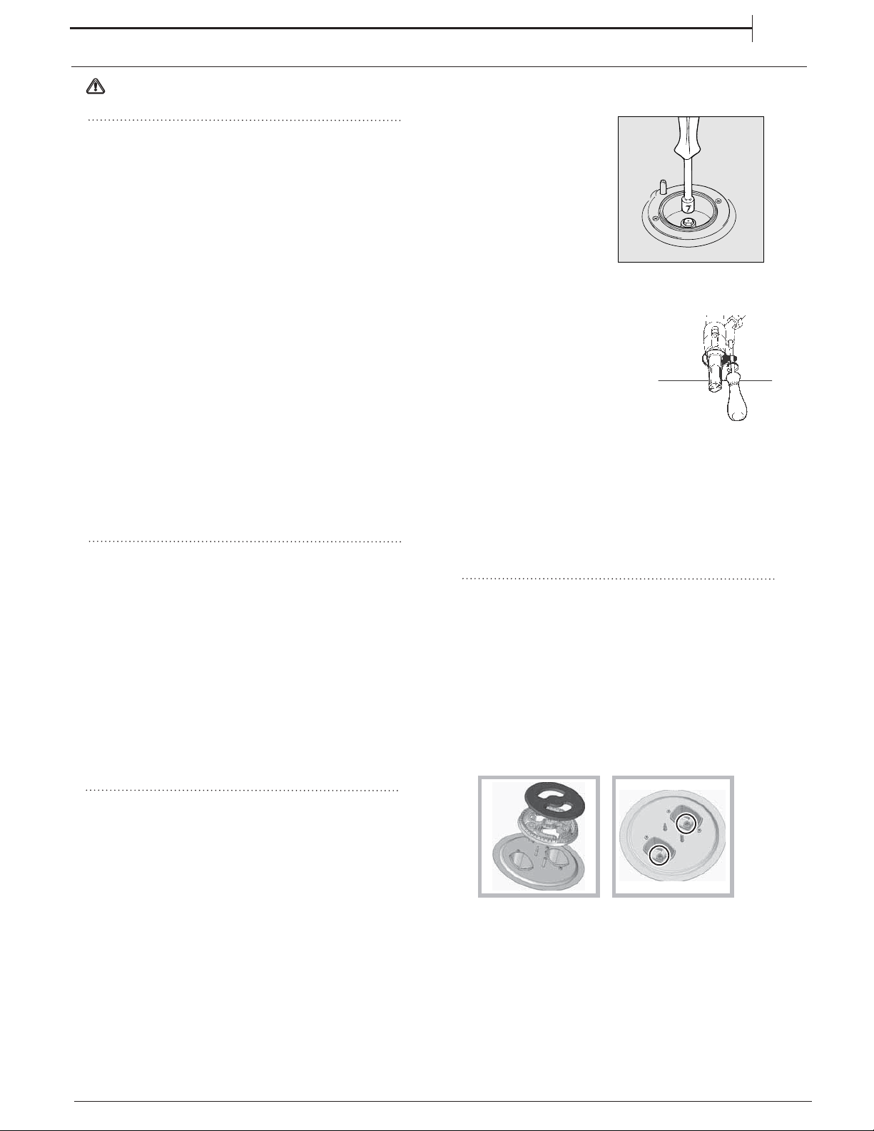
b) Replacing the burner nozzles on the hob:
•remove the grids and slide the burners from their
housings;
• unscrew the nozzles
using a 7 mm socket
spanner, and replace
them with nozzles for
the new type of gas
(see table 1 “Burner and
nozzle characteristics”).
•replace all the
components by
repeating the steps in
reverse order.
INSTALLATION TIPS
c )c )
c )c )
c ) Minimum regulation of the hob burners:
• turn the tap to minimum;
• remove the knob and adjust
the regulation screw, which is
positioned in or next to the tap
pin, until the flame is small
but steady.
In the case of liquid gas, the regulation screw
must be adjusted to the minimum setting.
• check that the flame does not turn off when
you turn the tap quickly from high to low.
d )d )
d )d )
d ) Regulating the primary air of the burners:
The primary air of the burners requires no regulation.
EN
WARNING : This operation must be perfomed
by a qualified technician
On completion of the operation, replace the old rating
sticker with one indicating the new type of gas used.
Replacing the Triple ring burner nozzles
1. Remove the pan supports and lift the burners out of
their housing. The burner consists of two separate
parts (see pictures).
2. Unscrew the nozzles using a 7 mm socket spanner.
Replace the nozzles with models that are configured
for use with the new type of gas (see Table 1). The
two nozzles have the same hole diameter.
3. Replace all the components by completing the
above operations in reverse order.
• Adjusting the burners primary air :
Does not require adjusting.
• Setting the burners to minimum:
1. Turn the tap to the low flame position.
2. Remove the knob and adjust the adjustment screw,
which is positioned in or next to the tap pin, until the
flame is small but steady.
3. Having adjusted the flame to the required low
setting, while the burner is alight, quickly change the
position of the knob from minimum to maximum and
vice versa several times, checking that the flame
does not go out.
Gas connection
V
V
Z
• Pry the fixing tab “V” and remove the oven burner
• Unscrew the oven burner nozzle using the socket
spanner for the nozzles
“Z”“Z”
“Z”“Z”
“Z”, or a 7 mm socket
spanner, and replace it with a nozzle suited to the
new type of gas (see Table 1).
Take particular care handling the spark plug
wires and the thermocouple pipes.
• Replace all the parts, following the steps
described above in the reverse order.
b )b )
b )b )
b ) Minimum regulation of the main and top gas
oven burner with thermostat:
• light the burner as described in the
paragraph the oven knob” of the
instruction booklet.
• turn the knob to
MaxMax
MaxMax
Max for about 10 minutes
and then turn the knob to the
MinMin
MinMin
Min
setting;
• remove the knob;
• regulate the screw positioned outside the
thermostat pin until the flame is
small but
steady.
! !
! !
In the case of liquid gas, the regulation screw
must be screwed in to the bottom.
• check that the burner does not turn off
whenwhen
you turn the knob from Max
to Min and and
when you open and close the oven door quickly.
Adapting the gas grill to different types of gas
Replacing the nozzle of the grill burner:
On completion of the operation, replace the old
rating sticker with one indicating the new type of gas
used. This sticker is available from our Service
Centres.
NoteNote
NoteNote
Note
Should the pressure of the gas used be different (or
vary) from the recommended pressure, it is
necessary to fit a suitable pressure regulator onto
the inlet pipe in compliance with current National
Regulations relative to “regulators for channelled
gas”.
If the appliance is connected to a liquid gas supply, the
bypass screw must be set to a minimum.
While the burner is alight, quickly change the position of the
knob from minimum to maximum and vice versa several times,
checking that the flame is not extinguished.
Upon completion of adjustment, reseal using sealing
wax or an equivalent material.
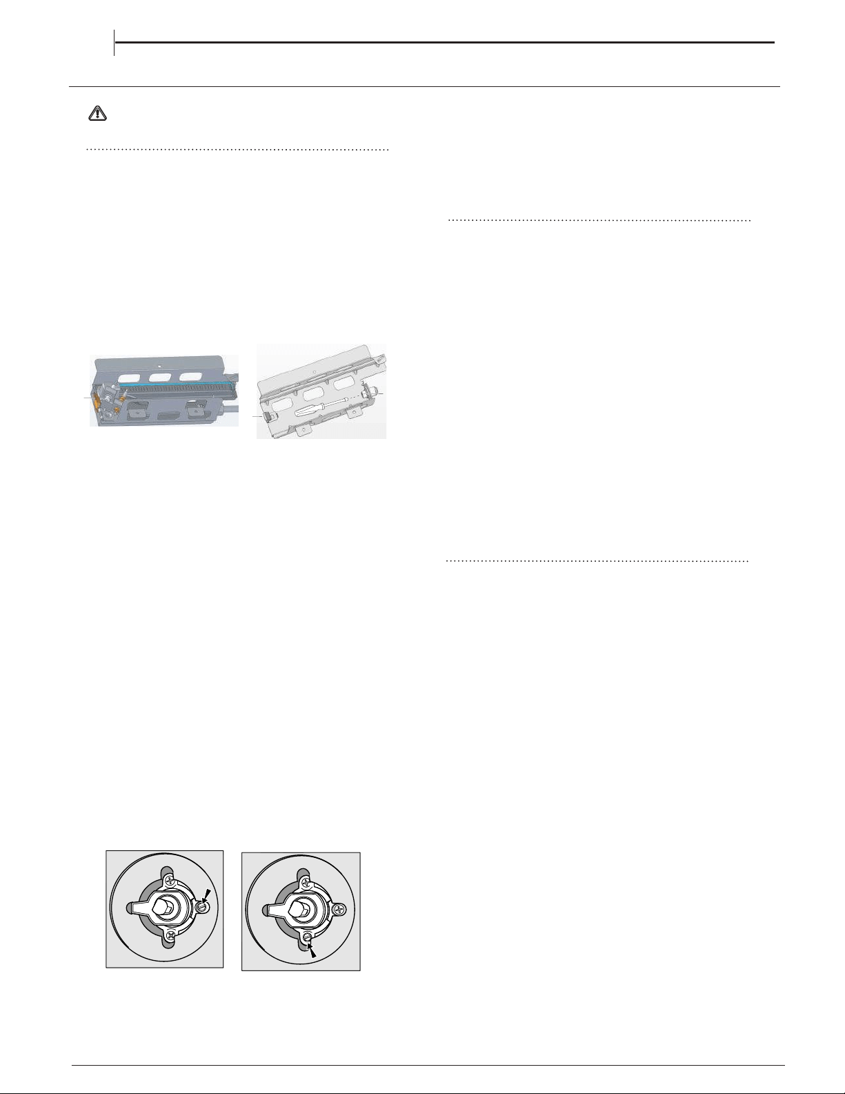
1. Remove the enamelled baffle at the front of the grill
(2 screws).
2. Remove the screw on the right hand side of the
burner and gently slide the burner off the injector.
3. Using a 7mm socket, replace the grill injector as
appropriate (see table on previous page).
4. Re-assemble the burner and baffle.
Adapting to different types of gas (main and top
oven)
In order to adapt the oven to a different type of gas
with respect to the gas for which it was
manufactured (indicated on the label), follow these
simple steps:
a)a)
a)a)
a) Replacing the oven burner nozzle
• open the oven door fully
• pull out the sliding oven bottom
unscrew the two screws and take off the shield
protecting the burner (in main oven burner only).
�
10
V
V
Z
• Pry the fixing tab “V” and remove the oven burner
• Unscrew the oven burner nozzle using the socket
spanner for the nozzles
“Z”“Z”
“Z”“Z”
“Z”, or a 7 mm socket
spanner, and replace it with a nozzle suited to the
new type of gas (see Table 1).
Take particular care handling the spark plug
wires and the thermocouple pipes.
• Replace all the parts, following the steps
described above in the reverse order.
b )b )
b )b )
b ) Minimum regulation of the main and top gas
oven burner with thermostat:
• light the burner as described in the
paragraph the oven knob” of the
instruction booklet.
• turn the knob to
MaxMax
MaxMax
Max for about 10 minutes
and then turn the knob to the
MinMin
MinMin
Min
setting;
• remove the knob;
• regulate the screw positioned outside the
thermostat pin until the flame is
small but
steady.
! !
! !
In the case of liquid gas, the regulation screw
must be screwed in to the bottom.
• check that the burner does not turn off
whenwhen
you turn the knob from Max
to Min and and
when you open and close the oven door quickly.
Adapting the gas grill to different types of gas
Replacing the nozzle of the grill burner:
On completion of the operation, replace the old
rating sticker with one indicating the new type of gas
used. This sticker is available from our Service
Centres.
NoteNote
NoteNote
Note
Should the pressure of the gas used be different (or
vary) from the recommended pressure, it is
necessary to fit a suitable pressure regulator onto
the inlet pipe in compliance with current National
Regulations relative to “regulators for channelled
gas”.
If the appliance is connected to a liquid gas supply, the
bypass screw must be set to a minimum.
While the burner is alight, quickly change the position of the
knob from minimum to maximum and vice versa several times,
checking that the flame is not extinguished.
Upon completion of adjustment, reseal using sealing
wax or an equivalent material.
1. Remove the enamelled baffle at the front of the grill
(2 screws).
2. Remove the screw on the right hand side of the
burner and gently slide the burner off the injector.
3. Using a 7mm socket, replace the grill injector as
appropriate (see table on previous page).
4. Re-assemble the burner and baffle.
Adapting to different types of gas (main and top
oven)
In order to adapt the oven to a different type of gas
with respect to the gas for which it was
manufactured (indicated on the label), follow these
simple steps:
a)a)
a)a)
a) Replacing the oven burner nozzle
• open the oven door fully
• pull out the sliding oven bottom
unscrew the two screws and take off the shield
protecting the burner (in main oven burner only).
�
INSTALLATION TIPSINSTALLATION TIPS
EN
WARNING : This operation must be perfomed
by a qualified technician
11
Power supply voltage and frequency: 230-240V a.c.
50-60 Hz.
The supply cable must be positioned so that it
never reaches at any point a temperature 50°C
higher than the room temperature. The cable must
be routed away from the rear vents. Should you
require it, you may use a longer cable, however, you
must ensure that the cable supplied with the
appliance is replaced by one of the same
specifications in accordance with current standards
and legislation.Your appliance is supplied with a 13
amp fused plug that can be plugged into a 13 amp
socket for immediate use. Before using the
appliance please read the instructions below.
Replacing the fuse:
When replacing a faulty fuse, a 13 amp ASTA
approved fuse to BS 1362 should always be used,
and the fuse cover re-fitted. If the fuse cover is lost,
the plug must not be used until a replacement is
obtained.
Replacement fuse covers:
If a replacement fuse cover is fitted, it must be of
the correct colour as indicated by the coloured
marking or the colour that is embossed in words on
the base of the plug. Replacements can be obtained
directly from your nearest Service Depot.
Removing the plug:
If your appliance has a non-rewireable moulded plug
and you should wish to remove it to add a cable
extension or to re-route the mains cable through
partitions, units etc., please ensure that either:
• the plug is replaced by a fused 13 amp re-
wireable plug bearing the BSI mark of approval.
or:
• the mains cable is wired directly into a 13 amp
cable outlet, controlled by a switch, (in
compliance with BS 5733) which is accessible
without moving the appliance.
For appliances with a rating greater than 13 amp
(eg: electric hob, double ovens and freestanding
electric cookers etc.) the mains cable must be wired
into a cooker output point with a rating of 45 amp. In
this case the cable is not supplied.
Disposing of the plug:
Ensure that before disposing of the plug itself, you
make the pins unusable so that it cannot be
accidentally inserted into a socket. Instructions for
connecting cable to an alternative plug:
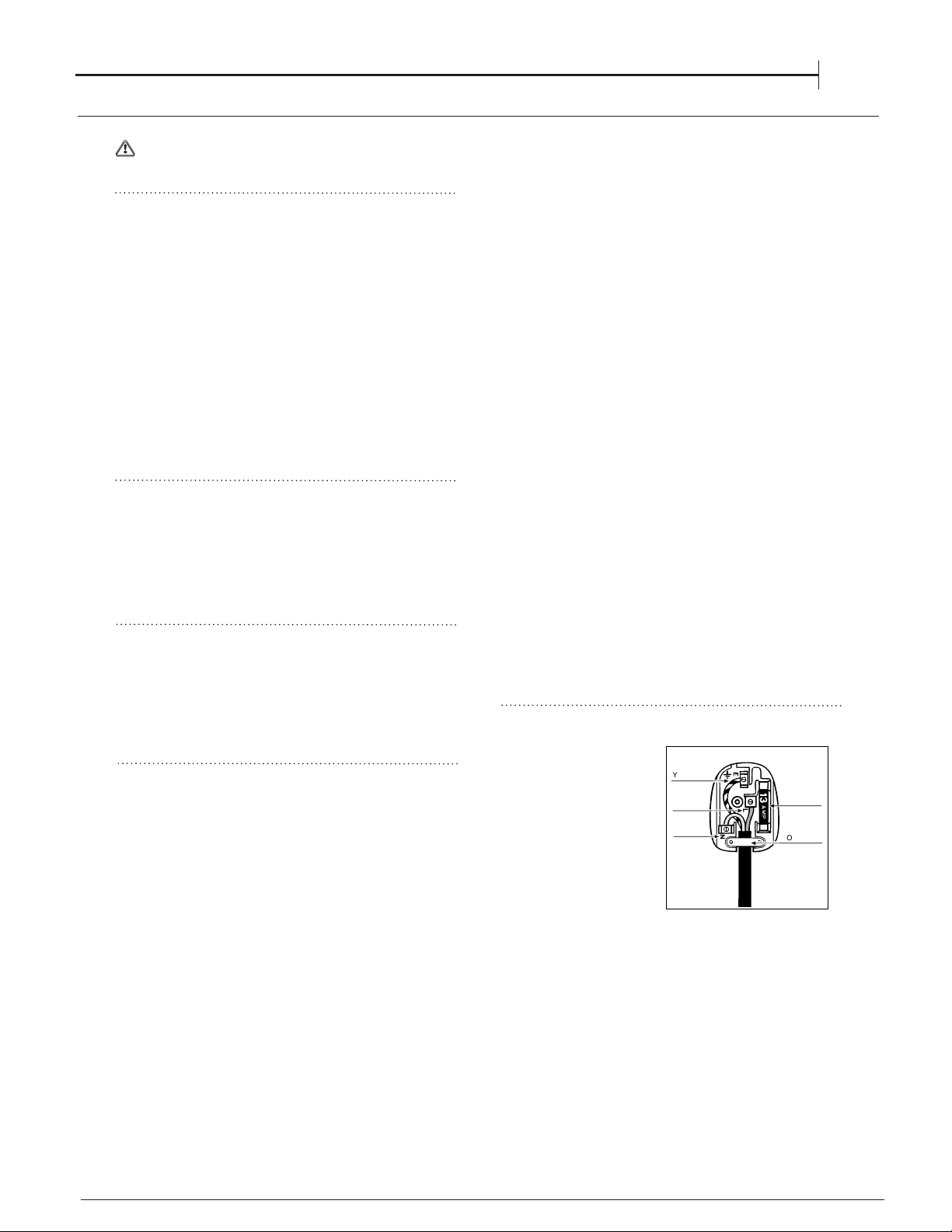
The wires in the mains lead are coloured in
accordance with the following code:
Green & Yellow - Earth
Blue - Neutral
Brown - Live
If the colours of the wires in the mains lead do not
correspond with the coloured markings identifying
the terminals in your plug, proceed as follows:
Connect Green & Yellow wire to terminal marked “
EE
EE
E”
or
66
66
6 or coloured Green or Green & Yellow.
Connect Brown wire to terminal marked “
LL
LL
L” or
coloured Red.
Connect Blue wire to terminal marked “
NN
NN
N” or
coloured Black.
If a 13 amp plug (BS 1363) is used it must be fitted
with a 13 amp fuse. A 15 amp plug must be
protected by a 15 amp fuse, either in the plug or
adaptor or at the distribution board. If you are in any
doubt about the electrical supply to your machine,
consult a qualified electrician before use.
How to connect an alternative plug:
The wires in this mains
lead are coloured in
accordance with the
following code:
BL U EBL U E
BL U EBL U E
BL U E “
NEUTRALNEUTRAL
NEUTRALNEUTRAL
NEUTRAL”
(“
NN
NN
N”)
B R O W NB R O W N
B R O W NB R O W N
B R O W N “
LIVELIVE
LIVELIVE
LIVE”
(“
LL
LL
L”)
GREEN ANDGREEN AND
GREEN ANDGREEN AND
GREEN AND
YEL L O WYEL L O W
YEL L O WYEL L O W
YEL L O W “
EARTHEARTH
EARTHEARTH
EARTH” (“
EE
EE
E”)
GREEN &
�
YELLOW
BROWN
BLUE
13 amp fuse
CROSS-BAR
�
CORD GRIP
WARNING.
If the electric supply fails to this appliance you must
not use the grill or ovens.
WARNING.
If the electric supply fails to this appliance you must
not use the grill or ovens.
ELECTRICAL CONNECTION
EN
WARNING : This operation must be perfomed
by a qualified technician
ACCESSORIES
DAILY USE
12
FIRST TIME USE
Using the hob
Lighting the burners
For each BURNER knob there is a complete ring
showing the strength of the flame for the relevant
burner.
To light one of the burners on the hob:
1. Bring a flame or gas lighter close to the burner.
2. Press the BURNER knob and turn it in an
anticlockwise direction so that it is pointing to the
maximum flame setting E.
3. Adjust the intensity of the flame to the desired
level by turning the BURNER knob in an
anticlockwise direction. This may be the minimum
setting C, the maximum setting E or any position in
between the two.
If the appliance is fitted with
an electronic lighting
device*(C) (
see figure
),
press the BURNER knob
and turn it in an
anticlockwise direction,
towards the minimum flame
setting, until the burner is lit. The burner might be
extinguished when the knob is released. If this
occurs, repeat the process, holding the knob down
for a longer period of time.
Since the hob burners are equipted with a
safety device (X), press and hold the BURNER knob
for approximately 3-7 seconds to keep the flame
alight and to activate the device.
If the flame is accidentally extinguished, switch off
the burner and wait for at least 1 minute before
attempting to relight it.
To switch the burner off, turn the knob until it
reaches the stop position •.
Advice when using burners
For the burners to work in the most efficient way
possible and to save on the amount of gas
consumed, it is recommended that only pans which
have a lid and a flat base are used. They should
also be suited to the size of the burner.
To identify the type of burner, please refer to the
diagrams contained in the paragraph “Burner and
nozzle specifications.”
For models equipped with a reducer grid, the latter
must be used only for the auxiliary burner, when
pans with a diameter of less than 12 cm are used.
Burner � Cookware Diameter (cm)
Semi Fast (S) 16 - 20
Auxiliary (A) 10 - 14
Triple Crown (TC) 24 - 26
EN
LEVEL COOKING TIPS
1 - 2 – 3
Ideal for softening butter, gently melting chocolate in
bagnemarie, thawing small portions, creaming risotto, keeping
warm small portions of just-cooked preparation
4 - 5
Ideal for slow-cook recipes (rice,sauces,roast,fish)
using liquids (water, wine, broth), and for creaming pasta,
maintainin
g
a
g
entle boilin
g
6 - 7
Ideal for sautéing, stewing vegetables, cooking for longer
p
eriod
,
p
reheat
ing
accessories
,
cook
ing
until cream
y
8 - 9
Ideal for browning, starting to cook, bringing liquids to the boil
quickly, frying deep-frozen products, grilling meat and fish,
maintainin
g
a live
ly
boil
10
Ideal for rapidly increasing the temperature of food
or for heat
ing
u
p
li
q
uids
(
water
)
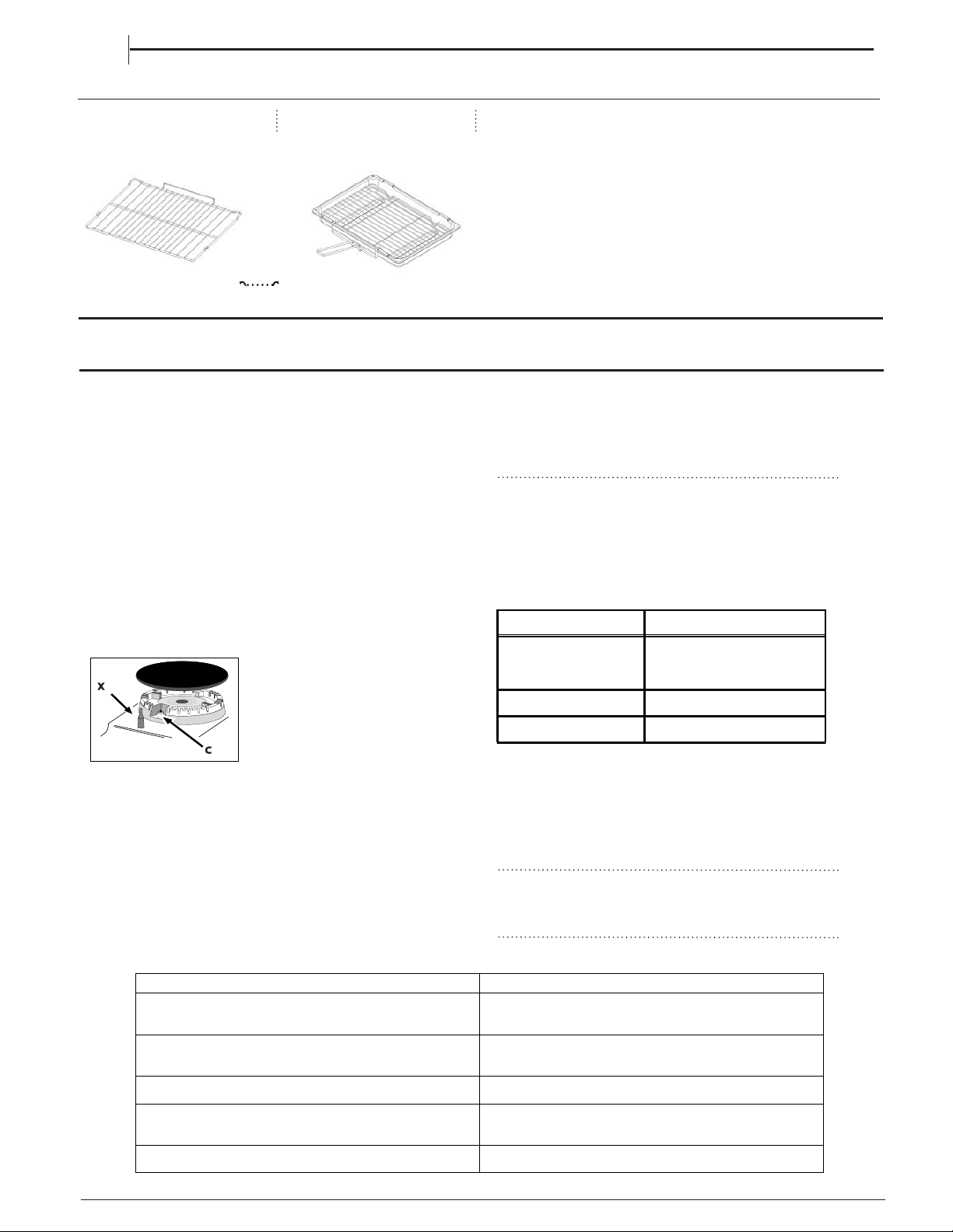
The number and type of accessories may vary depending on which model
is purchased. Other accessories that are not supplied can be purchased
separately from the After-sales Service.
GRID
KIT GRILL PAN
The burner turns on while heating and turns off when
reaching the temperature set a few times during cooking
cycles.
If for any reason the oven burner has not lit after 15
seconds, turn the control knob to the OFF position.
Leave the main oven door open and wait for at least 1
minute before attempting to light the burner again.
Never place dishes over the burner.
An odour may be noticed when first using the oven -
this should cease after a short period of use.
RELIGHTING THE BURNER
In the event of the burner flames being accidentally
extinguished, turn off the burner control and do not
attempt to re-ignite the burner for at least one minute.
COLD START COOKING
Anything requiring long slow cooking such as
casseroles and rich fruit cakes can be put into a cold
oven. Satisfactory results can also be obtained with
creamed mixture, rich pastries or yeast mixtures, but
for perfection we recommend preheating the oven
for about 15 minutes at the gas mark you require for
cooking.
TOP OVEN
The top oven can be used to cook small quantities
of food or used in conjunction with the main oven to
provide additional cooking space.
The top oven is fitted with a safety device that will
cut off the gas supply to the burner if the flame is
extinguished for any reason. Each time the top oven is
used, the safety device has to be activated by pushing
and holding in the control knob for 3 seconds after the
gas has lit.
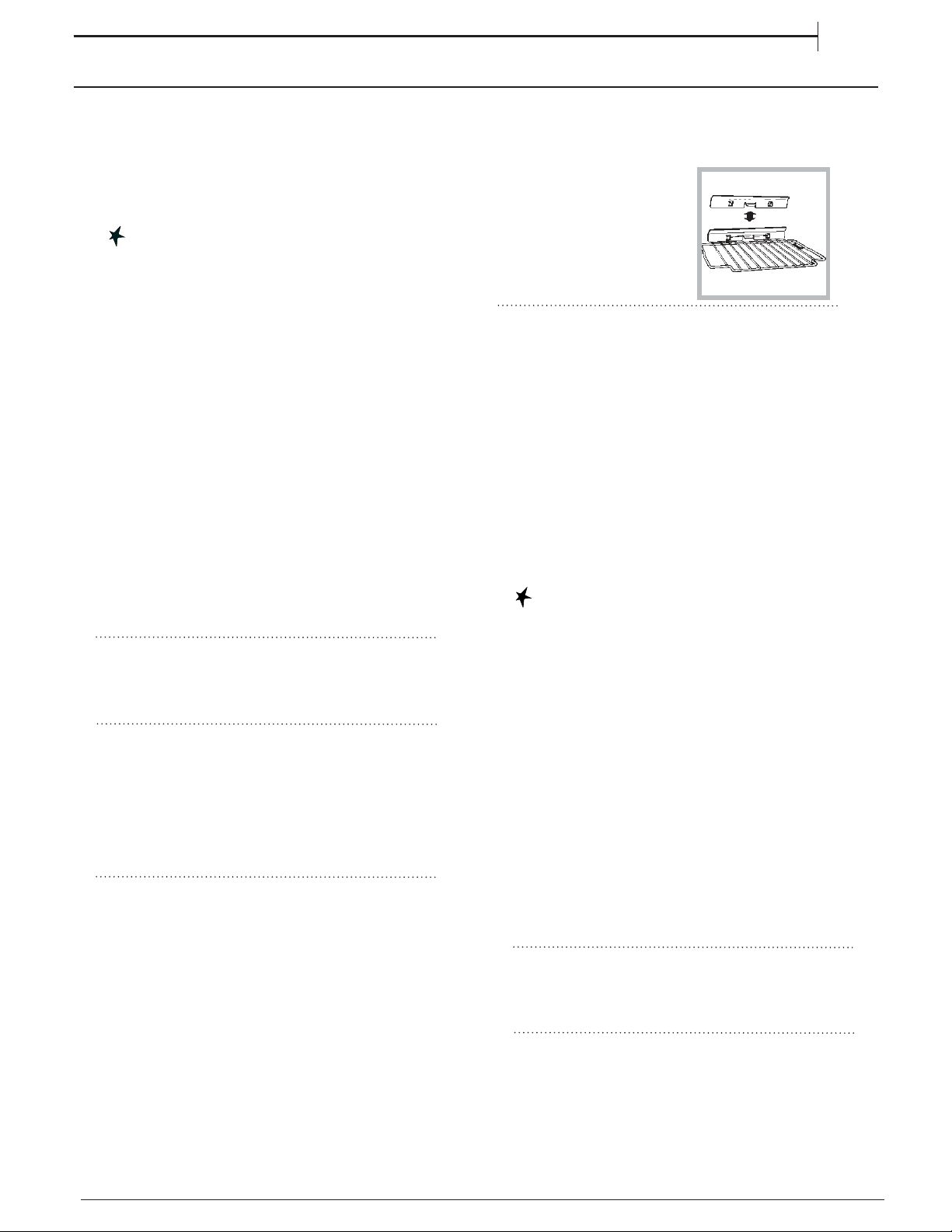
The shelf in the top oven has a heat shield fitted at
the rear. The shield can be removed for cleaning and
the stop and then lifting at the
front to withdraw.
The maximum size of baking
tray that should be used is
300mm x 350mm (12” x 14”).
TO USE THE TOP
OVEN
1. Check that the heat shield is fitted to the shelf.
2. Place the top oven shelf in the appropriate position
4. Push in and turn the control knob fully anti-
clockwise. Continue to push in the control knob
for a further 3 seconds after the gas has lit to allow
time for the safety device to operate. If the burner
extinguishes when the control knob is released,
repeat the procedure ensuring the control knob
is fully depressed and allowing more time for the
safety device to operate.
For the models with the electronic ignition button (
), press the button and then turn the knob.
5. Turn the control knob clockwise to the required
setting. (refer to cooking chart).
6. To turn off, turn the control knob clockwise to the
symbol O.
A gentle flow of air will be blown from underneath the
control panel when the grill or top oven is in use.
If the fan fails to blow air when the top oven is in use,
you must stop using and switch off the oven burner
immediately and contact our service department.
3- Ensure that the appliance is connected to the
correct electrical supply and switched on
Always push the door firmly closed to ensure that there
is no loss of heat through the door seal.
If for any reason the oven burner has not lit after 15
seconds, turn the control knob to the OFF position.
Leave the top oven door open and wait for at least 1
minute before attempting to light the burner again.
1. Best results are obtained by pre-heating the oven
for about 15 minutes.
2. Food which is higher than or will rise above 125mm
(5”) cannot be cooked in the top oven.
Never place dishes over the burner.
An odour may be noticed when first using the oven -
this should cease after a short period of use.
In the event of the burner flames being accidentally
extinguished, turn off the burner control and do not
attempt to re-ignite the burner for at least one minute.
RELIGHTING THE BURNER
13
FIRST TIME USE
DAILY USE
EN
For the models with the electronic ignition button (
), press the button and then turn the knob.
3. Turn the control knob clockwise to the required
setting.
5. To turn off, turn the control knob fully clockwise the
the symbol O .
4. Ensure that the appliance is connected to the
correct electrical supply and that the supply is
switched on.
MAIN OVEN
TO USE THE MAIN OVEN
1. Place the oven shelves in the appropriate positions
2. Turn the burner knob in an anticlockwise direction
so that it is pointing to the 9. step flame setting.
When the cooker is first used an odour may be emitted,
When first using the cooker ensure that the room is well
this will cease after a period of use.
ventilated (e.g. open a window or use an extractor fan)
and that persons who may be sensitive to the odour avoid
any fumes. It is suggested that any pets be removed from
the room until the smell has ceased. This odour is due to
temporary finish on oven liners and elements and also any
moisture absorbed by the insulation.
The control system for the main oven may be different
for best cooking results. It has a safety stop to prevent
it from being pulled out too far when attending to food.
The shelf is removed from the oven by pulling it out to
to your previous appliance. To maintain a constant
temperature, and give you the best results, the burner
switches off once the set temperature is reached and
then relights when the temperature drops. This means
you will hear the ignition sequence on a regular basis
grilling, but should be replaced when using the oven
during cooking.
haracteristics of the gas section
Model Gas section
Rated power
kW (1)
II2H3+
14,60 (G20)
(1) The values in g/h refer to the capacities with liquid gas (Butane, Propane).
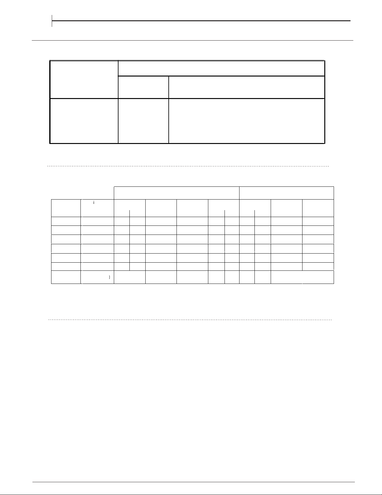
GAS NOZZLE TABLE
14
GAS NOZZLE TABLEGAS NOZZLE TABLEGAS NOZZLE TABLEGAS NOZZLE TABLE
EN
CCC
Table 1 Liquid Gas Natural Gas
Burner
D
i
ameter
(mm)
Thermal Power
kW (p.c.s.*)
Nominal Reduced
ByPass
1/100
(mm)
Nozzle
1/100
(mm)
Fl
ow
*
g/h
*** **
Thermal Power
kW (p.c.s.*)
Nominal
Reduced
N
ozz
l
e
1/100
(mm)
Fl
ow
*
l/h
Triple Crown
(TC)
130
3
.3
1
.
5
0
63 2x65
2
3
6
2
3
2
3.3 1.50
2
x
9
9
309
Semi Fast
(Medium)(S)
75
2
.
0
0
.
4
30 69
145 143
2.
0
0
.
4
104 190
Auxiliary
(Small)(A)
55
1.0 0.4
30 50
73 71
1.0 0.4
78 95
Supply
Pressures
Nominal (mbar)
Minimum (mbar
)
Maximum
(mb
ar)
28
30
37
20 25
35 45
20
17
25
Table 1 Liquid Gas Natural Gas Table 1 Liquid Gas Natural Gas
)
Main Oven
Grill
Top Oven
-
-
-
2.6 0.6
30
77
167
164
2.6
0.6
120
248
3.5
-
96
247
243
3.7
150
(X)
352
1.8
0.6
36
65
138
136
1.8
0.6
104
171
* At 15°C and 1013 mbar - dry gas
** Propane P.C.S. = 50,37 MJ/Kg
*** Butane P.C.S. = 49,47 MJ/Kg
Natural P. C.S. = 37,78 MJ/m3
Gas category
14,40 (1047 g/h-G30)
(1028 g/h-G31)
CD67G0C2CJ/UK
The front right hob burner injector should be used as the pressure test point.
The grill is fitted with a safety device that will cut off the
gas supply to the burner if the flame is extinguished
for any reason. Each time the grill is used, the safety
device has to be activated by pushing and holding in
the control knob for 3 seconds after the gas has lit.
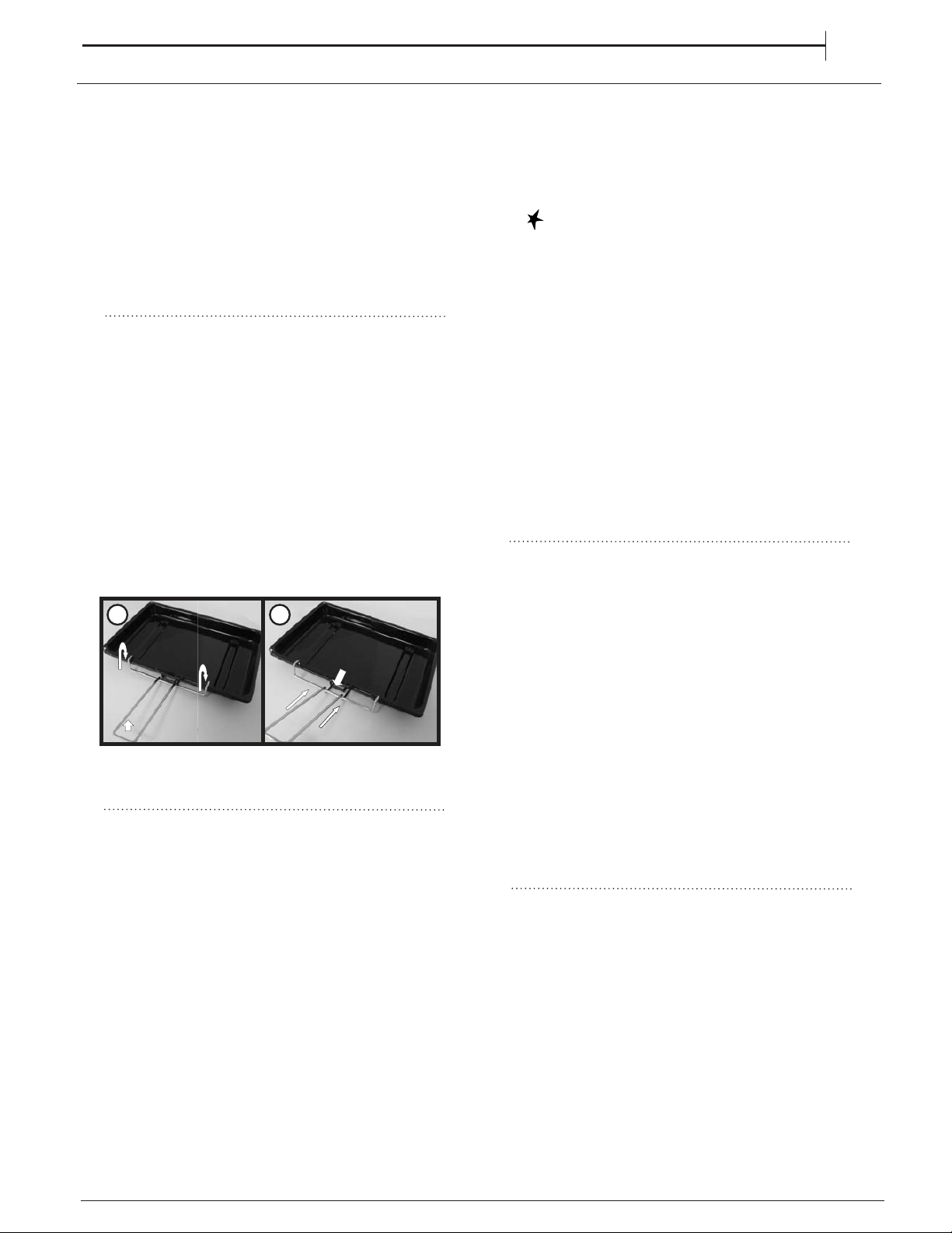
Grill Pan Handle
The grill pan handle is detachable from the pan to
facilitate cleaning and storage. Fix the pan handle
securely before use:
1. Fit the handle to the grill pan so that the external
hooks embrace the edge of the pan (fig. 1)
2. Make sure that the middle part of the handle fits
exactly the protruding support of the pan (fig .2) and
holds the pan from the bottom.
The food must be placed on the rack in the grill pan.
Position the grill pan on top of the oven rack. The best
results are achieved by placing the oven rack on the
uppermost shelves. Pouring a little water into the grill
pan will make the collection of grease particles more
efficient and prevent the formation of smoke.
The grill pan can be stored in the top compartment with
the handle attached by placing the shelf in the middle
or lower position and tilting the grill pan over the rear
edge of the shelf.
TO USE THE GRILL
1. Open the top oven/grill door and remove the grill
pan.
2. Remove the heat shield from the rear of the shelf
for maximum grilling area.
3. Place the shelf in the appropriate position.
5. Push in and turn the control knob clockwise to the
large flame symbol. Continue to push in the control
knob for a further 3 seconds after the gas has lit,
to allow time for the safety device to operate. If
the burner extinguishes when the control knob is
released, repeat the procedure ensuring the control
knob is fully depressed and allowing more time for
the safety device to operate.
For the models with the electronic ignition button (
), press the button and then turn the knob.
6. Slide the grill pan along the shelf towards the rear
of the grill compartment until it stops.
7. To turn off, turn the control knob anti-clockwise to
the symbol O.
The grill cannot be used at the same time as the top
oven. If for any reason the grill burner has not lit after
15 seconds, turn the control knob to the off position,
leave the grill door open and wait for at least one
minute before attempting to light the burner again. An
odour may be noticed when first using the grill this
should cease after a short period of use.
Do not use the grill with the door closed.
Do not cover the grill pan or grid with aluminium
foil as this can hold fat, intensify the heat
and create a fire hazard.
RELIGHTING THE BURNER
In the event of the burner flames being accidentally
extinguished, turn off the burner control and do not
attempt to re-ignite the burner for at least one minute.
Grilling can be started from cold but for best results
preheat for approximately two minutes. Most cooking
is done with the heat on full, but it may be desirable to
reduce it for thicker pieces of meat or for keeping food
warm.
For au gratin dishes eg. Macaroni Cheese and
meringue toppings eg. Baked Alaska, place the dish
on the floor of the grill compartment. The base of the
grill pan can be used for warming fruit garnishes on the
reduced setting.
Always ensure that the grill pan handle is correctly
fitted to the grill pan.
1
2
A gentle flow of air will be blown from underneath the
control panel when the grill or top oven is in use. If the
fan fails to blow air when the grill is in use, you must
stop using and switch off the grill burner immediately
and contact our service department.
4. Ensure that the appliance is connected to the
correct electrical supply and and that the supply is
switched on.
Do not use the grill without an electrical supply to the
cooker.
Remove heat shield from shelf when grilling for maximum
grilling area.
GRILL
EN
15
16
CLOCK MINUTE MINDER OPERATION
////
EN
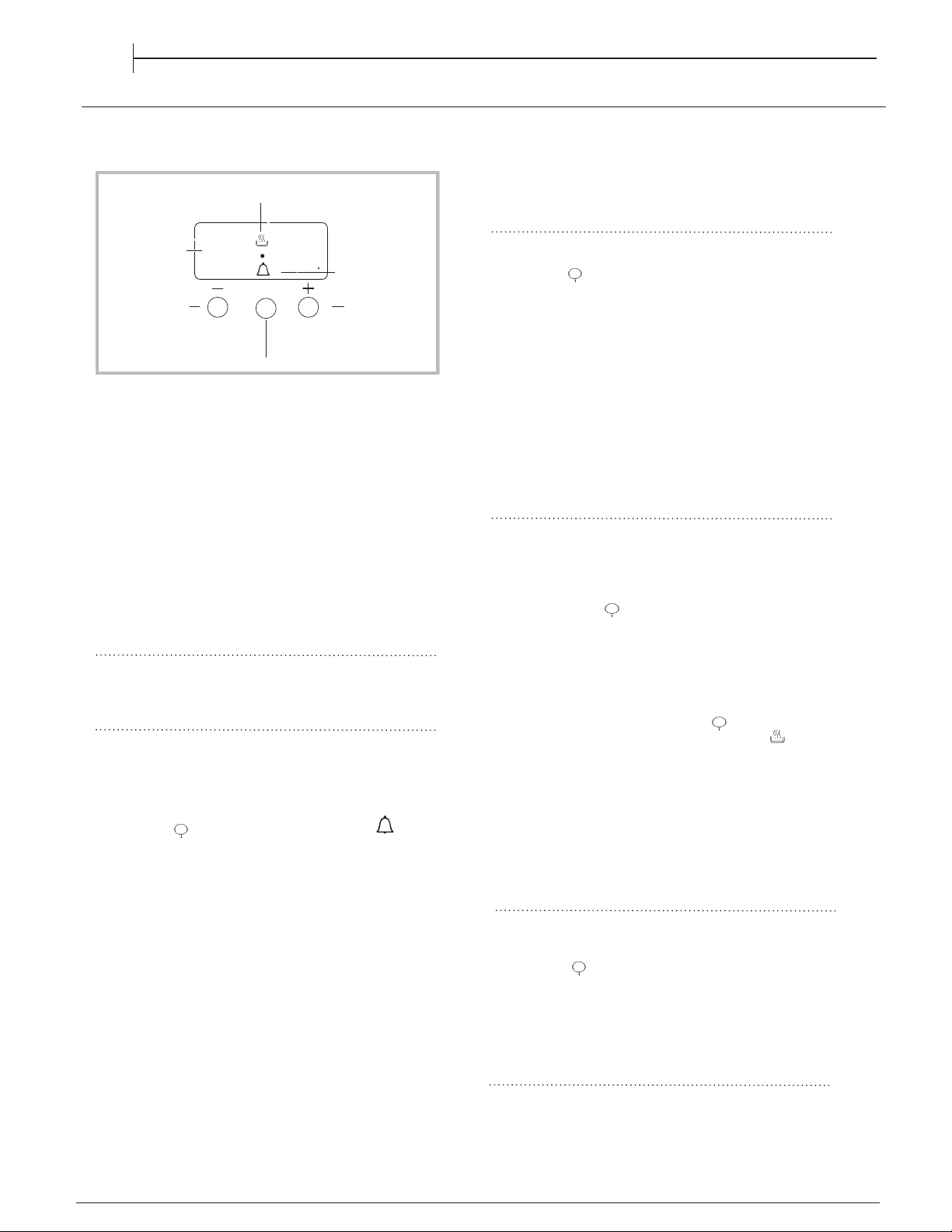
DISPLAY
MODE
button
AUTO
icon
TIMER icon
DECREASE TIME
button
INCREASE TIME
button
•• ••
Setting the clock
The clock may be set when the oven is switched off
or when it is switched on, provided that the end time of
a cooking cycle has not been programmed previously.
After the appliance has been connected to the mains,
or after a blackout, the 00:00
digits on the DISPLAY will begin to flash.
1. Press the
"+" and "-" button simultaneously
2. Use the “+” and “-” buttons to adjust the time; if you
press and hold either button, the display will scroll
through the values more quickly, making it quicker and
easier to set the desired value.
Setting the minute minder
This function does not interrupt cooking and does not
affect the oven; it is simply used to activate the buzzer
when the set amount of time has elapsed.
1. Press the button several times until the
icon
and the three digits on the display begin to flash.
2. Use the “+” and “-” buttons to set the desired time; if
you press and hold either button, the display will scroll
through the values more quickly, making it quicker and
easier to set the value.
3. Wait for 5 seconds, If you press the buttom one more time
the display will then show the time as it counts down.
When this period of time has elapsed the buzzer will be
activated.
Programming cooking
A cooking mode must be selected before
programming can take place.
Programming the cooking duration
1. Press the button several times until
icon
and the DUR digits on the DISPLAY begin to flash.
2. Use the “+” and “-” buttons to set the desired
duration; if you press and hold either button, the
display will scroll through the values more quickly,
making it quicker and easier to set the value.
3. Wait for 5 seconds, after that the icon will be visible
4. When the set time has elapsed
and the oven will stop cooking
you will hear a buzzer sounds. Press any button to stop the
buzzer.
• For example: it is 9:00 a.m. and a time of 1 hour and
15 minutes is programmed. The programme will
stop automatically at 10:15 a.m.
Setting the end time for a cooking mode
1. Follow steps 1 to 3 to set the duration as detailed
above.
2. Next, press the button until the
text END on the diplay
begin to flash.
3. use the “+” and “-” buttons to adjust the cooking end
time; if you press and hold either button, the display
will scroll through the values more quickly, making it
quicker and easier to set the desired value.
4. Wait for 5 seconds or press the button again,
5. When the set time has elapsed, the oven will stop cooking
and a buzzer sounds.
Press any button to stop it.
Programming has been set when the icon
is illuminated.
• For example: It is 9:00 a.m. and a duration of 1 hour
has been programmed. 12:30 is scheduled as the
end time. The programme will start automatically at
11:30 a.m.
Cancelling a programme
To cancel a programme:
• press the button until the icon corresponding to
the setting you wish to cancel and the digits on the
display are flashing. Press the “-” button until the
digits 00:00 appear on the display.
• Press and hold the “+” and “-” buttons; this will
cancel all the settings selected previously, including
timer settings.
P
on the display.
When the cooking process start, the symbol is visible
on the display.
A
Changing the buzzer frequency
The buzzer signal frequency can be changed by
touching the "- " repeatedly.
Than the colon between hours and minutes is flashing.
COOKING PROCESS
icon
P
A
A
A
P
P
P
P
17
EN
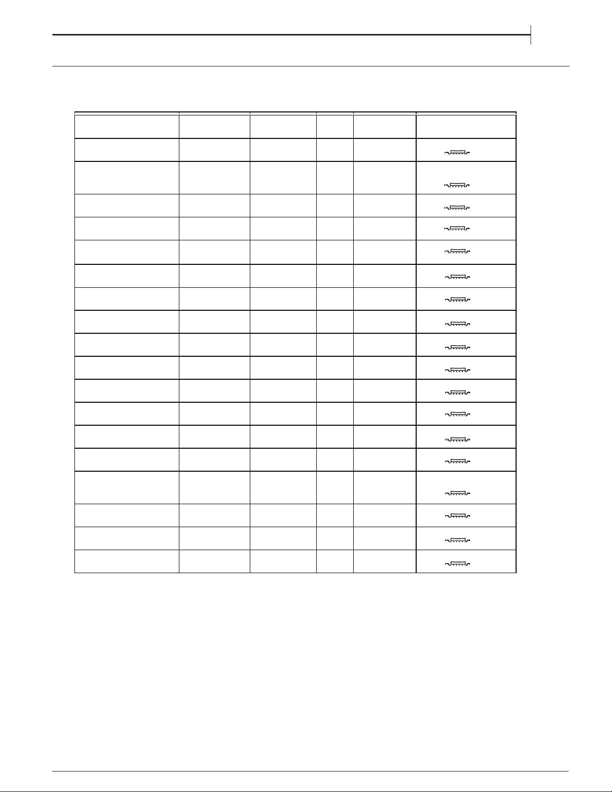
COOKING TABLE
MAIN OVENMAIN OVENMAIN OVENMAIN OVEN
RECIPE FUNCTION
PREHEAT
Time
(m
inutes
)
GAS
MARK
DURATION
(M
inutes
)
LEVEL (L-number) AND
ACCESSORIES
Leavened cakes / Sponge
cakes CONVENTIONAL 10 3 - 4 20 - 50
Filled cake
(cheese cake, strudel, fruit
pie)
CONVENTIONAL 10 3 - 4 20 - 50
Cookies / Shortbread CONVENTIONAL 5 2 - 3 50 - 70
Small cakes / Muffin CONVENTIONAL 10 3 - 4 20 - 50
Choux buns CONVENTIONAL 10 4 - 5 20 - 50
Pizza / Bread / Focaccia
Thin CONVENTIONAL 15 8 - 9 15 - 50
Pizza / Bread / Focaccia
Thick CONVENTIONAL 15 4 - 6 30 - 50
Savoury pies (vegetable
p
ie
,
q
uiche
)
CONVENTIONAL 10 4 40 - 60
Vols-au-vent / Puff pastry
crackers CONVENTIONAL 15 4 - 6 15 - 40
Lasagne / Flans / Baked
p
asta / Cannelloni CONVENTIONAL 15 4 - 6 30 - 65
Lamb / Veal / Beef / Pork
1 k
g
CONVENTIONAL 10 4 - 5 50 - 120
Chicken / Rabbit / Duck 1
kg
CONVENTIONAL 15 6 - 7 25 - 50
Turke
y
/ Goose 3 k
g
CONVENTIONAL 10 3 - 4 130 - 170
Fish fillets / Steaks CONVENTIONAL 15 4 - 6 20 - 30
Stuffed vegetables
(tomatoes, courgettes,
aube
rg
ines
)
CONVENTIONAL 15 4 - 6 40 - 80
Ve
g
etable
g
ratin CONVENTIONAL 15 4 - 6 20 - 30
Roast
p
otatoes CONVENTIONAL 15 4 - 8 40 - 80
Le
g
of lamb / Shanks CONVENTIONAL 15 6 - 8 50 - 100
3
3
3
3
3
3
3
3
3
3
2
2
2
2
2
2
1
4
18
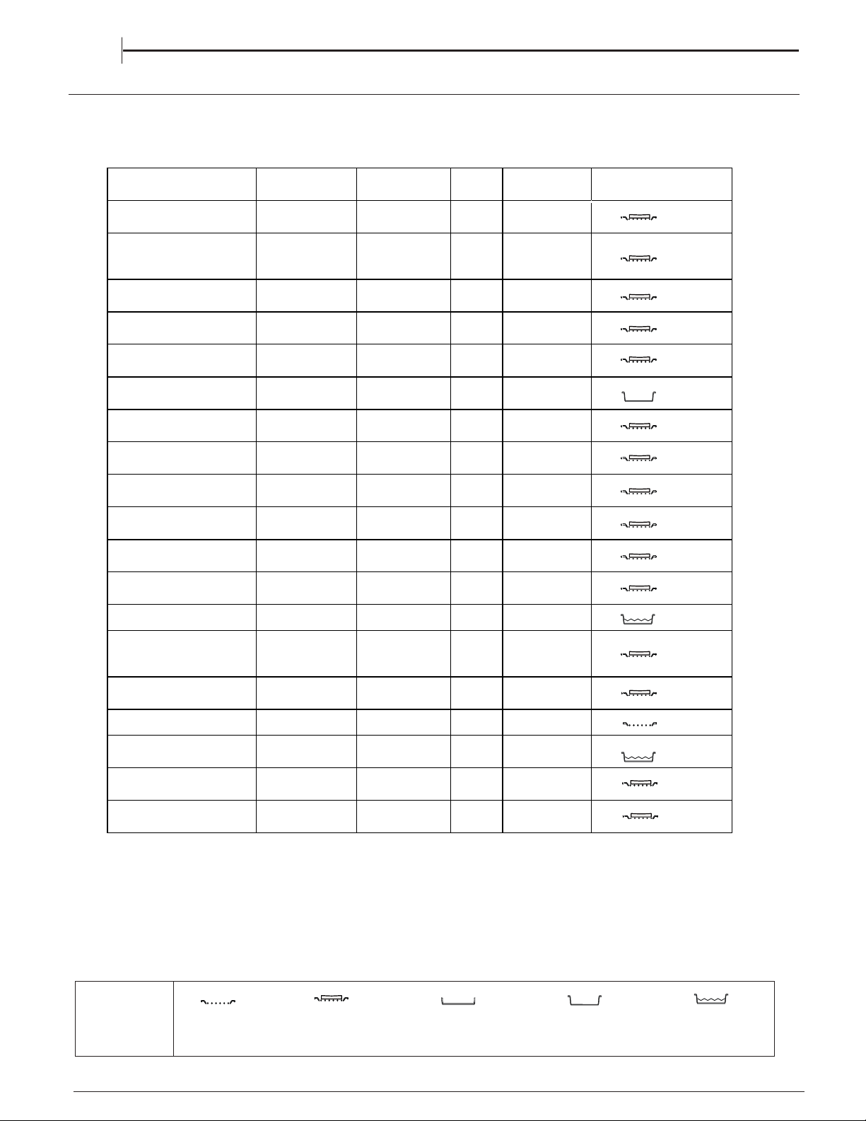
COOKING TABLE
EN
TOP OVENTOP OVENTOP OVENTOP OVENTOP OVENTOP OVEN
ACCESSORIES
Wire shelf
Baking dish or cake tin on
the wire shelf
Baking tray/Drip tray or
Baking dish on the wire
shelf
Drip tray / Baking tray
Drip tray / Baking tray with
00 ml of water
5
RECIPE FUNCTION
PREHEAT
Time
(
Minutes
)
GAS
MARK
DURATION
(M
inutes
)
LEVEL (L-number) AND
ACCESSORIES
Leavened cakes / Sponge
cakes CONVENTIONAL 10' 3 - 4 30 - 70
Filled cake
(cheese cake, strudel, fruit
pie)
CONVENTIONAL 10' 3 150 - 250
Cookies / Shortbread CONVENTIONAL 10' 2 15 - 30
Small cakes / Muffin CONVENTIONAL 10' 3 - 4 15 - 30
Choux buns CONVENTIONAL 10' 4 - 5 20 - 50
Pizza / Bread / Focaccia
Thin CONVENTIONAL 15' 7 - 8 15 - 30
Pizza / Bread / Focaccia
Thick CONVENTIONAL 15' 4 - 6 30 - 50
Savoury pies (vegetable
p
ie
,
q
uiche
)
CONVENTIONAL 10' 4 40 - 60
Vols-au-vent / Puff pastry
crackers CONVENTIONAL 15' 4 - 6 15 - 40
Lasagne / Flans / Baked
p
asta / Cannelloni CONVENTIONAL 15' 4 - 6 30 - 65
Lamb / Veal / Beef / Pork
1 k
g
CONVENTIONAL 10' 4 - 5 50 - 120
Chicken / Rabbit / Duck 1
kg
CONVENTIONAL 15' 6 - 7 25 - 50
Fish fillets / Steaks GRILL 10' MAX 15 - 35
Stuffed vegetables
(tomatoes, courgettes,
aube
rg
ines
)
GRILL 10' MAX 30 - 60
Ve
g
etable
g
ratin GRILL 10' MAX 15 - 40
Toast GRILL 10' MAX 3 - 5
Sausages / Kebabs /
Sp
are ribs / Hambu
rg
ers GRILL 10' MAX 20 - 40
Roast
p
otatoes CONVENTIONAL 15' 4 - 8 40 - 80
Le
g
of lamb / Shanks CONVENTIONAL 15' 6 - 8 50 - 100
1
1
1
1
1
2
2
2
2
2
2
2
2
2
2
1
1
2
2

CLEANING AND MAINTENANCE
19
EN
Carefully slide the first
inner glass towards you,
taking care not to allow the
glass to fall.
Now the external glass
panel can be washed.
2. 2. 2. 2. 2.
3.3.3.3.
Ensure the glass panel is not subjected toEnsure the glass panel is not subjected to
Ensure the glass panel is not subjected toEnsure the glass panel is not subjected to
Ensure the glass panel is not subjected to
any sharp mechanical blows. any sharp mechanical blows.
any sharp mechanical blows. any sharp mechanical blows.
any sharp mechanical blows. Take particular
care not to damage the inner surface which is coated
with a heat reflective layer. After cleaning, rinse and
dry with a soft cloth. For slight soiling the inner glass
panel may be cleaned, while still warm, without
removing it from the door.
glass removed.
To reassemble the oven doors proceed with inserting
the glass panels in the reverse order, pushing gently
every panel directly into the liners, so that the warning
glass removed.glass removed.glass removed.glass removed.glass removed.
Oven must not be operated with inner door
glass removed.
sign printed on the glass is correctly legible.
4.
Oven must not be operated with inner doorOven must not be operated with inner doorOven must not be operated with inner doorOven must not be operated with inner door
Removing the retaining
Removing the retaining
bar
depress carefully
both sides of the bar.
Pull the trim up gently
until the retainer is
released.
the clips on
Open the door to .
1111
.....
Cleaning the glass door with 2 panels
TOP OVEN DOORS
30
°
20
TURN OFF THE MAIN SWITCH AND ENSURE THE COOKER IS COLD BEFORE CLEANING.
BEFORE SWITCHING ON AGAIN, ENSURE THAT
ALL CONTROLS ARE IN THE OFF POSITION.
Do not use steam cleaning
equipment.
Use protective gloves during all
operations.
Carry out the required
operations when the oven is cold.
Disconnect the appliance from
the power supply.
Do not use wire wool, abrasive
scourers or abrasive/corrosive
cleaning agents, as these could
damage the surfaces of the
appliance.
CLEANING AND MAINTENANCE
Disconnect the appliance from the power supply.
CLEANING THE HOB SURFACE
warm water and neutral solution.
Stainless steel surfaces may be stained by calcareous
water or aggressive detergents if left in contact for too long.
(water, sauce, coee, etc.) should be wiped
Clean with warm water and neutral detergent, and then dry
a soft cloth or chamois. Remove baked-on dirt with specic
stainless steel surfaces.
NOTE: clean stainless steel only with soft cloth or sponge.
Do not use abrasive or corrosive products, chlorine-based
or pan scourers.
Do not use steam cleaning appliances.
Do not use ammable products.
Do not leave acid or alkaline substances, such as vinegar,
mustard, salt, sugar or lemon juice on the hob.
CLEANING THE HOB PARTS
Clean glass and enamelled parts only with soft cloth or sponge.
Grids, burner caps and burners can be removed to be cleaned.
Clean them by hand with warm water and non-abrasive
detergent removing any food residues and checking that
openings is clogged.
Rinse and dry.
Ret burners and burner caps correctly in the respective
When replacing the grids, make sure that the panstand area is
with the burner.
Models equipped with electrical ignition plugs and safety
require thorough cleaning of the plug end in order to
ensure correct operation. Check these items frequently, and if
with a damp cloth. Any baked-on food
toothpick or needle.
NOTE: to avoid damaging the electric ignition device,
do not use it when the burners are not in their housing.
EXTERIOR SURFACES
• Clean the surfaces with a damp microfibre cloth.
If they are very dirty, add a few drops of pH-neutral
detergent. Dry them with a dry cloth.
• Do not use corrosive or abrasive detergents. If any of
these products inadvertently comes into contact with
the surfaces of the appliance, clean immediately with
a damp microfibre cloth.
INTERIOR SURFACES
• After every use, leave the oven to cool and then
clean it, preferably while it is still warm, to remove any
deposits or stains caused by food residues To dry any
condensation that has formed as a result of cooking
foods with a high water content, let the oven to cool
completely and then wipe it with a cloth or sponge.
• Clean the glass in the door with a suitable liquid
detergent.
CLEANING THE OVEN SURFACE
ACCESSORIES
Soak the accessories in a washing-up liquid solution
after use, handling them with oven gloves if they
are still hot. Food residues can be removed using a
washing-up brush or a sponge.
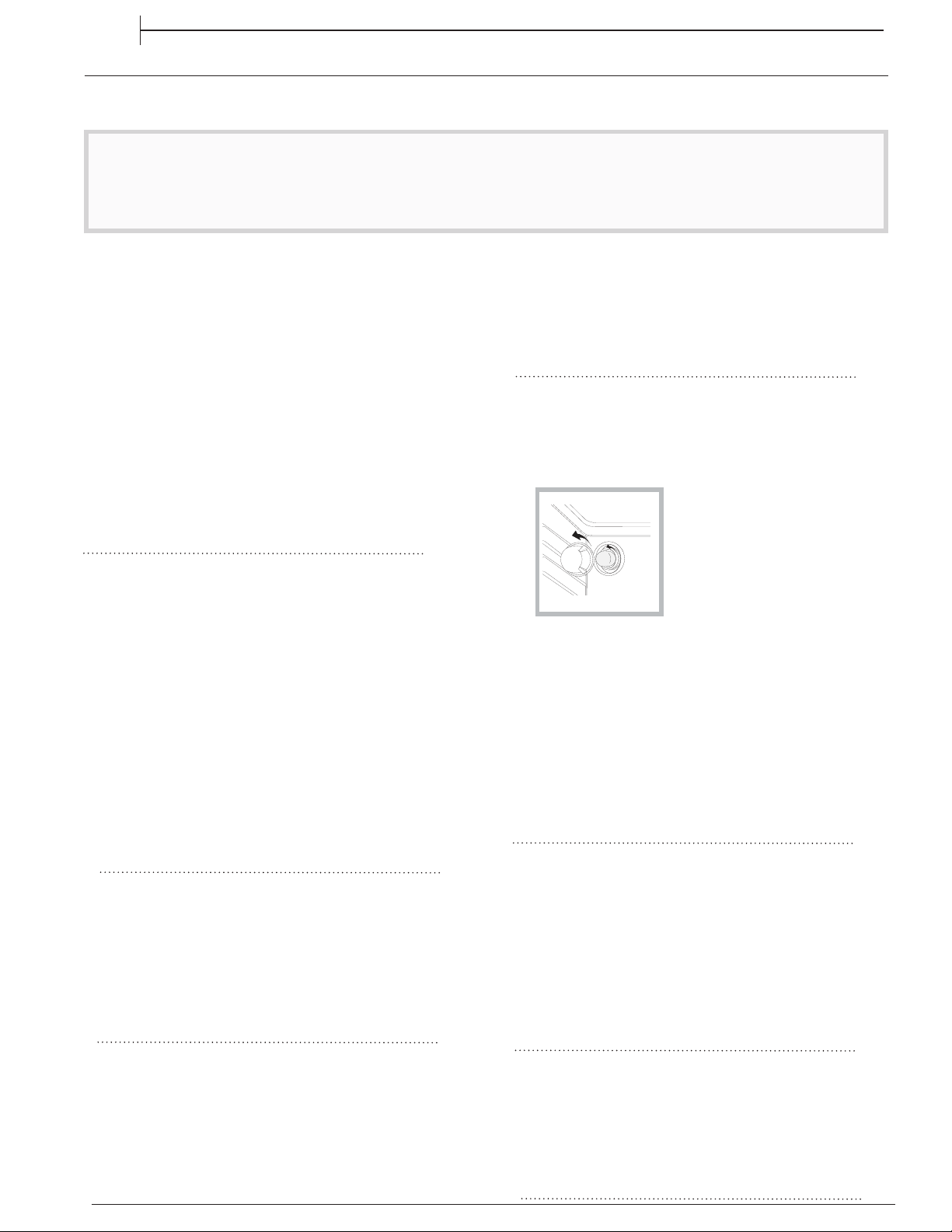
REPLACING THE LIGHT
1.
Disconnect the oven from the power supply.
2.
Unscrew the cover from the light, replace the bulb
and screw the cover back on the light.
3.
Reconnect the oven to the power supply.
Note: Use 40 W/230 V type
The bulb used in the product is specically designed for
domestic appliances and is not suitable for general room
lighting within the home (EC Regulation 244/2009).
G9
Note: Use 40 W/230 V type
Light bulbs are available from our After-sales Service.
- Do not handle bulbs with your bare hands as your
ngerprints could damage them. Do not use the oven until
the light cover has been retted.
The bulb used in the product is specically designed for The bulb used in the product is specically designed for The bulb used in the product is specically designed for
domestic appliances and is not suitable for general room
lighting within the home (EC Regulation 244/2009).
Light bulbs are available from our After-sales Service.
- Do not handle bulbs with your bare hands as your
ngerprints could damage them. Do not use the oven until
the light cover has been retted.
All the enamelled and glass parts should be cleaned with
Any od spills
away beore they dry.
for
of the burner
aligned
device
necessary, clean them
should be removed with a
fo
with
cleaners
cleaners
none
housings.
(Only in some models)
CATALYTIC CLEANING
These are panels coated with a special enamel, which
is able to absorb the fat released by food as it cooks.
This enamel is quite strong, so that the various
accessories (racks, dripping pans, etc.) can slide along
them without damaging them. White marks may appear
on the surfaces; these are not a cause for concern.
Nevertheless, the following should be avoided:
-scraping the enamel with sharp objects (a knife, for
example);
-using detergents or abrasive materials.
LOWER THE TOP HEATING ELEMENT
The top heating element of the grill can be lowered
to clean the upper panel of the oven: xtract the heating
E
element from its seating, then lower it. To return the
heating element to its position, lift it up, pull it slightly
towards you and make sure that the tab support is in its
proper seating.
(main oven)
EN
This product contains a light source of energy
efficiency class G
WWW
A complete product specification, including the energy efficiency ratings for this oven, can be read and
downloaded from our website
21
Problem Possible cause Solution
The oven or the burner will not
switch on.
Power cut.
Disconnection from the
mains electricity.
Check for the presence of mains electrical power
and whether the oven is connected to the
electricity supply.
Wait at least one minute, then try to switch the
oven on again and see if the problem persists.
Gas supply interrupted. Check that the gas tap upstream of the oven is
open or that the liquid gas cylinder (if being used)
is not empty.
Switch-on procedure carried
out incorrectly.
Wait at least one minute and then repeat the steps
described in the “Daily use” section.
In the event of problems, turn the adjustment knob back to the position and open the oven door.
TROUBLESHOOTING
HOW TO READ THE COOKING TABLE
The table indicates the best function to use with
certain types of food cooked on a single shelf.
Cooking times start from the moment food is placed
in the oven, excluding pre-heating (where required).
Cooking temperatures and times are purely for
guidance and will depend on the amount of food and
type of accessory used. Use the lowest recommended
settings to begin with and, if the food is not cooked
enough, then switch to higher settings. Use the
accessories supplied and preferably dark-coloured
metal cake tins and baking trays. You can also use
Pyrex pans and accessories or ones made from china,
but bear in mind that cooking times will be slightly
longer. For best results, follow the recommendations
in the cooking table carefully when selecting which
of the supplied accessories to place on which of the
shelves.
USEFUL TIPS
AFTER-SALES SERVICE
To receive assistance, call the number given on the
warranty leaflet enclosed with the product or follow
the instructions on our website. Be prepared to
provide:
•
a brief description of the problem;
•
the exact model type of your product;
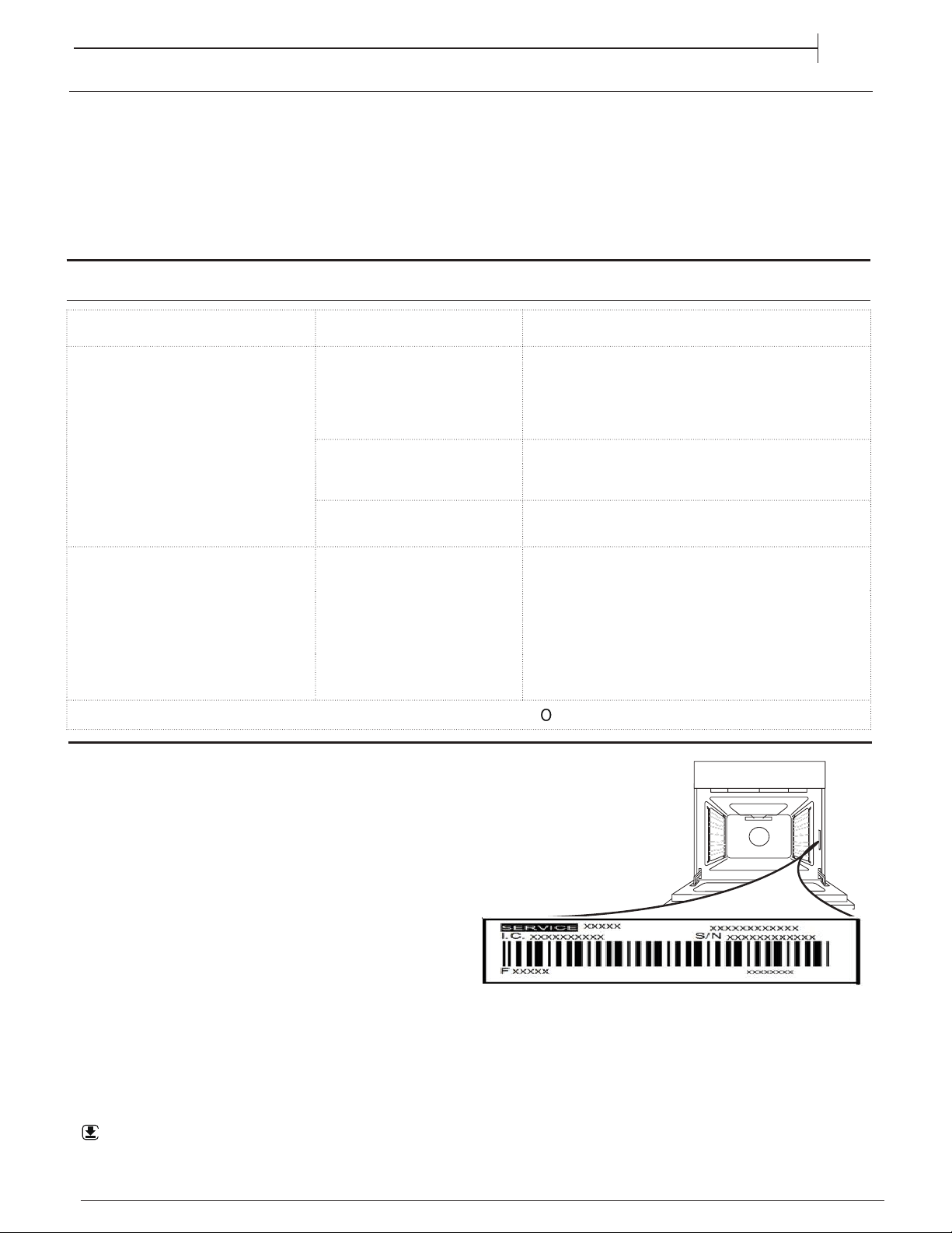
•
the assistance code (the number following the word
SERVICE on the identification plate attached to the
product, which can be seen on the inside edge when
the oven door is open);
•
your full address;
•
a contact telephone number.
Please note: If repairs are required, contact an
authorised service centre that is guaranteed to use
original spare parts and perform repairs correctly.
Please refer to the enclosed warranty leaflet for more
information on the warranty.
www.hotpoint.co.uk
EN
I can hear the ignition of the burner
regularly when using the main oven.
To maintain a constant temperature,
and give you the best results, the
burner switches off once the set
temperature is reached and then
relights when the temperature drops.
This means you will hear the ignition
sequence on a regular basis during
cooking.
No action, this is normal for perfect cooking results.
22
17mm - 0,67inch
max. 15 mm
Min. 420 mm
Min. 750 mm
65
600
750
65
23
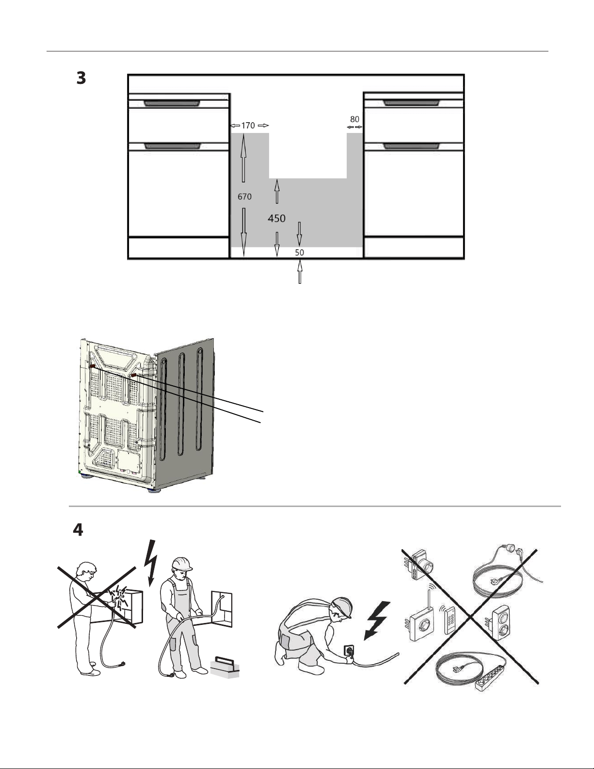
There are 2 spacers on the rear panel of the appliance (see Fig 1)
the spacers can be removed by the installer to allow the appliance
to be pushed back further in the aperture. This can only be done
if the requirements of BS 6172:2010 can still be met.
intended to prevent the appliance trapping the flexible hose.
If the flexible hose and it's rigid pipework connections are recessed,
Connecting to gas supply
Position the gas connection point such that it is located within the shaded area,
and the hose also hangs naturally within the shaded area.
Hot parts
Installation area
XEROX FABRIANO
Whirlpool EMEA S.p.A.
Via Carlo Pisacane n.1
20016 Pero (MI), Italy
VAT number: IT00693740425
24
www.hotpoint.co.uk
W11514551W11514551
12/2021 -
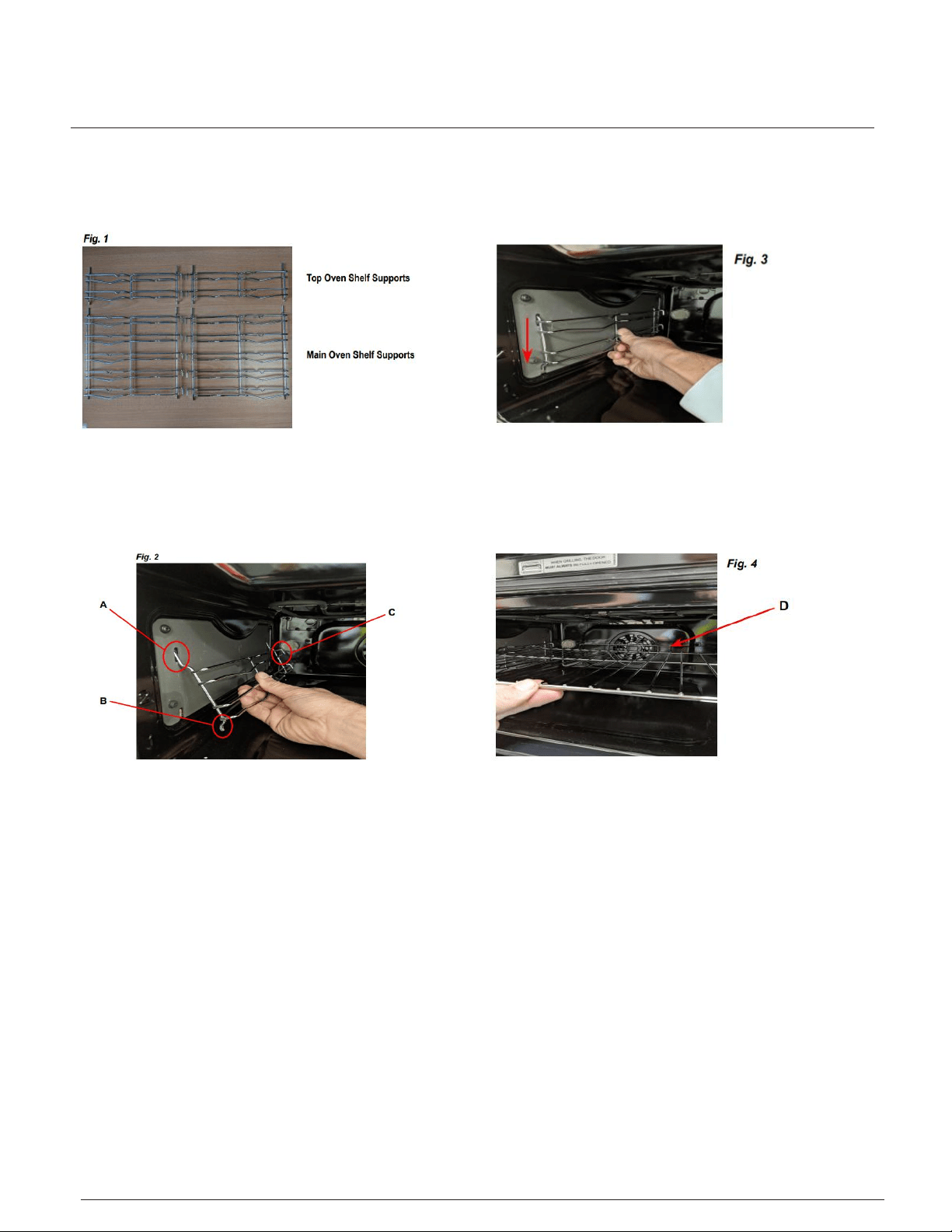
Your new cooker comes with 4 chrome shelf supports
There are 2 shelf supports for the top oven and 2
packed in the main oven along with the shelves.
for the bottom oven. See Fig. 1.
Fitting - Step 1
The top of the shelf supports engage in slots in the side
Note the rods ‘A’ are longer at the top than
‘B’ at the bottom, and the hooks ‘C’ are at the back of the
oven. It is important that the shelf supports
walls of the oven as in Fig. 2 below.
are fitted the correct way around!
Fitting - Step 2
Once engaged at the top, then push the bottom rods into
the shelf supports to lower slightly and engage. See Fig. 3.
the lower slots in the oven side walls. Now allow
This process should be repeated and all 4 shelf supports
fitted in the top and main ovens.
Fitting - Step 3
The shelves can now be fitted into the shelf supports
‘D’
that should be at the back of the oven as shown. See Fig. 4.
at the required heights. Note that there is pan guard
Your ovens are now ready to use !