Loading ...
Loading ...
ASSEMBLY
BOX CONTENTS
1257.797010WeedandGrassTrimmer
1LoosePartsKitContaining
...................2ea. 7962MachineScrews(ForTubes)
2ea.3935StopNuts
2ea.8268-tPointedScrews(ForGuards)
Iea. 6774-05FrontGuard
Iea, Q6796-15Guard&BladeAssy.
1ea.88-692-00Owner'sManual
Remove TRIMMER from carton and examine it thoroughly to
make sure it is not damaged.
Remove and discard protective plastic clips inserted in
handle tubes before assembly of trimmer.
TOOLS NEEDED FOR ASSEMBLY
• Medium Phillips screwdriver
• Adjustable wrench or pliers
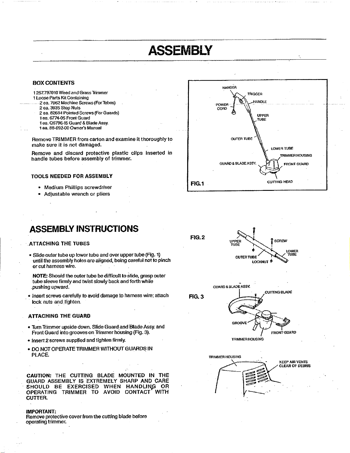
FIG,1
H/,J_G_R
" _'_ TRIGGER
UBE
OUTERTU8_
'_._ LOWER 'fUeE
. _lrRIMME_ HOUSING
GUARD & eLAOE ASSY. _ FRONT GUARD
CUTTING HEAD
ASSEMBLY INSTRUCTIONS
.ATTACHING THE TUBES
• Slide outer tube up lower tube and overupper tube (Fig, 1)
until the assembly holes are aligned, being careful not to pinch
or cut harness wire.
NOTE: Shouid the outer tube be difficult to slide, grasp outer
tube sleeve firmly end twist slowly back and forth while
.pushing upward.
•,, insert screws carefullyto avoiddamage to harness wire;attach
lock nuts and tighten.
ATTACHING THE GUARD
• Turn"l_immerupside down. Slide Guardand Blade Assy. and
Front Guard into grooves on Trimmer housing(Fig. 3).
• Insert 2 screws supp!ied and tighten firmly.
• DO NOT OPERATE TRIMMER WITHOUT GUARDS. IN
PLACE.
CAUTION-" THE CUTTING BLADE MOUNTED IN THE
GUARD ASSEMBLY IS EXTREMELY SHARP AND CARE
SHOULD BE EXERCISED WHEN HANDLIN_ OR
OPERATING TRIMMER TO AVOID CONTACT WITH
CUTTER.
IMPORTANT:
Remove protective cover from the cutting blade before
operating trimmer.
RG.2
FIG. 3
Y
UPP_ _ SCREW
TUBE "_,,_ f
OUTERTUBE "" _ "_U_
LOC_UT$
GUARD & BLADE ASSY.
CUT_NG et.A_
TRIMMERI_OL_NG
TRIMMER HOUSING
_" KE_:P AIR VENTS
Loading ...
Loading ...
Loading ...