Model#
GL1SS24TBD GL1SS30TBD
Gas Cooktop User’s Manual
Thank you for purchasing a Galanz product. Please read this manual carefully for correct usage and safety,
and keep for future reference. For service, support and warranty information, call 800-562-0738.
@2019 Galanz Americas Limited Company.

FPO
CONTENT
CONTENT
1
INSTALLATION
USE AND CARE
SAFETY NOTICE................................................................................................................ 2
RANGE HOOD OPERATIONS.............................................................................................18
TROUBLESHOOTING.........................................................................................................19
ELECTRIC SCHEMATIC.....................................................................................................21
WARRANTY
COVERAGE & EXCEPTIONS..............................................................................................24
DISCLAIMER......................................................................................................................25
CONTACT INFORMATION................................................................................................. 25
MAINTENANCE
CLEANING, REPLACING FILTER & LIGHTBULB................................................................ 22
SPECIFICATIONS....................................................................................................................... 4
PARTS SUPPLIED...................................................................................................................... 5
TOOLS REQUIRED.....................................................................................................................5
VENTING REQUIREMENTS........................................................................................................ 6
VENTING METHODS.................................................................................................................. 7
HEIGHT CLEARANCES & DUCT SIZE CALCULATOR................................................................ 8
CHARCOAL FILTER INSTALLATION & ELECTRICAL REQUIREMENTS......................................8
PREPARATION...........................................................................................................................10
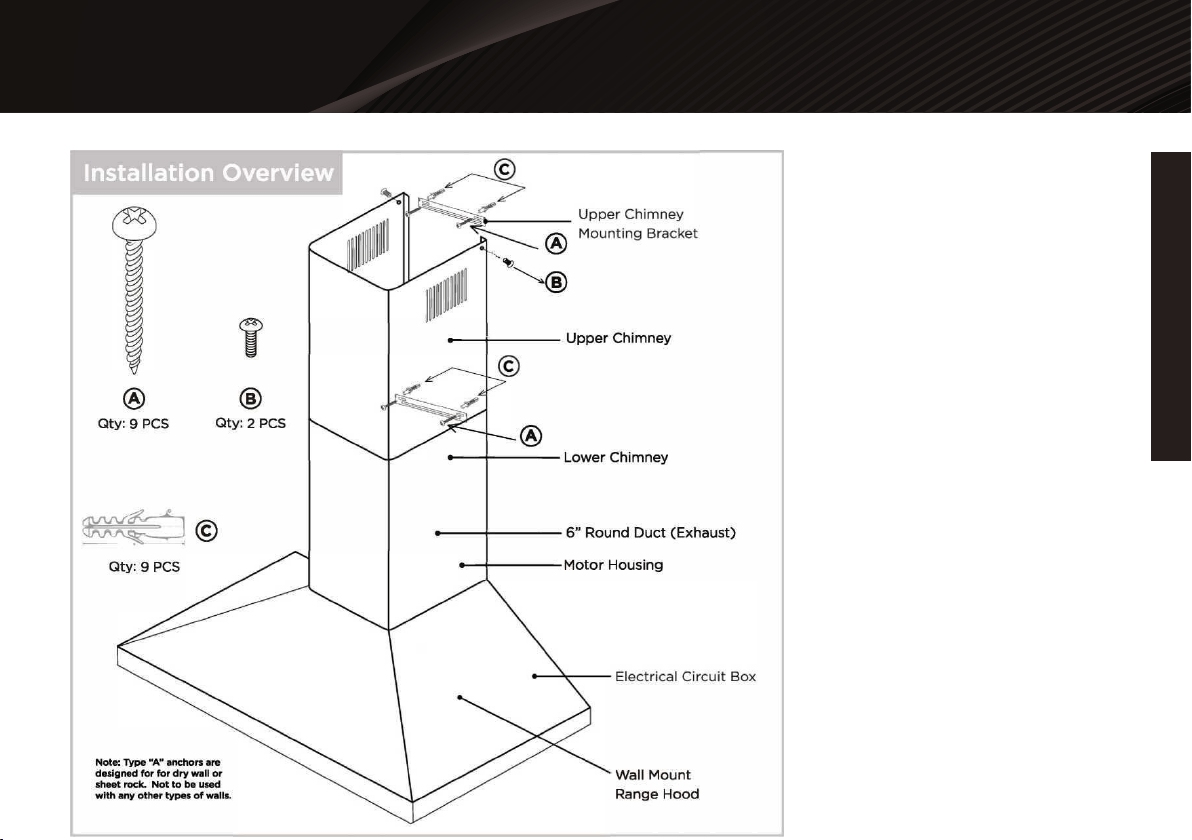
INSTALLATION OVERVIEW........................................................................................................ 12
INSTALLATION..... .....................................................................................................................13
FPO
INSTALLATION
INSTALLATION
2
READ ALL INSTRUCTIONS BEFORE INSTALLING
AND OPERATING THIS APPLIANCE
WARNING
Your safety and the safety of others is very important. We have
provided many important safety messages in this manual and on
your appliance. Always read and obey all safety messages. All safety
messages will tell you what the potential hazard is, tell you how to
reduce the chance of injury, and tell you what can happen if the
instructions are not followed.
This is the safety alert symbol. This symbol alerts you to potential
hazards that can hurt you and others. All safety messages will follow
the safety alert symbol “/tv’ and the word “WARNING”.
Excessive Weight Require three or more persons to move and install
this range hood. Spinal or other bodily injuries could occur if it is not.
WARNING
Light bulb become extremely hot when turned on. DO NOT touch
bulb until switched off and cooled. Touching hot bulbs could cause
serious burns.
WARNING
Severe Injury
Rotating fan can cause severe injury. Stay clear of fan when power is
present.
WARNING
Excessive Weight Require three or more persons to move and install
this range hood. Spinal or other bodily injuries could occur if it is not.
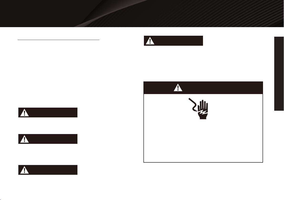
WARNING
Hazard of electrical shock!
Hazard of Burns!
Do not perform service on an electrically live system.
Disconnect the main electrical supply before servicing this
device. Touching electrical connectors or other exposed
electrical circuity inside this range hood when they energized
could result in death, serious bodily injury, or property
damage.
IMPORTANT SAFETY NOTICE

FPO
INSTALLATION
INSTALLATION
3
TO REDUCE THE RISK OF A STOVE TOP GREASE FIRE:
Ducted fans MUST always be vented to the outdoors.
DO NOT vent exhaust into spaces between walls, crawl spaces,
ceiling, attics or garages.
Any old duct work should be cleaned or replaced if necessary to
avoid the possibility of a grease fire. Check all joints on duct work
to insure proper connection and all joints should be properly
taped.
Use only metal ductwork and this unit MUST be grounded.
Before servicing or cleaning unit, switch power OFF at service
panel and lock service panel toprevent power from being
switched ON accidentally.
When cutting or drilling into wall or ceiling, be careful not to
damage electrical wiring or other hidden utilities.
All electrical wiring must be properly installed, insulated and
grounded.
Use this unit only in the manner intended by the manufacturer. If
you have questions, contact the vendor.
DO NOT touch the bottom side of the range hood directly after
usage because it may be hot. Wait until it has cooled.
Make sure to inspect shipment and it’s contents as soon
shipment is received.
Plug in and test range hood and all its functions, (refer to Range
Hood Operations, Page 15), directly after receiving shipment,
and before scheduling an installer.
Clean grease laden surfaces frequently.
Clean ventilating fan frequently.
Keep all surfaces clean from grease or oil build up.
Grease should not be allowed to accumulate on fan, baffle, spaces,
filter, grease tunnel and oil container.
Always turn range hood ON when cooking at high heat or when
cooking flaming foods. Use high settings on cooking range only
when necessary.
Never leave burners or cooktop at high settings unattended. Boil
overs cause smoking and greasy spillovers that may ignite. Heat oils
slowly on low or medium settings.
Always use appropriate cookware and utensils size.
Always use cookware appropriate for the size of the surface
element.
TO REDUCE THE RISK OF INJURY TO PERSONS IN THE EVENT
OF A STOVE TOP GREASE FIRE:
SMOTHER FLAMES with a close-fitting lid, cookie sheet, or metal
tray, then turn OFF the burner. BE CAREFUL TO PREVENT BURNS.
NEVER PICK UP A FLAMING PAN-you may be burned.
KEEP FLAMMABLE OR COMBUSTIBLE MATERIAL AWAY FROM
FLAMES. If the flames DO NOT go out immediately, EVACUATE
AND CALL THE FIRE DEPARTMENT or dial your local emergency
service immediately.
DO NOT USE WATER, including wet dishcloths or towels — a
violent steam explosion may result.
FPO
INSTALLATION
INSTALLATION
4
Use an extinguisher ONLY if:
Extinguish any open flame.
DO NOT turn on the range hood fan or any type of ventilator.
DO NOT turn on the lights or any type of appliance.
Open all doors and windows to disperse the gas. If you still smell
gas, call the gas company and fire department, or dial your local
emergency service immediately.
You know you have a Class A, B, C extinguisher, and you already
know how to operate it.
The fire is small and contained in the area where it is started.
The fire department is being called.
You can fight the fire while maintaining a safe exit path.
TO REDUCE THE RISK OF INJURY TO PERSONS IN THE EVENT
OF A GAS LEAKS:
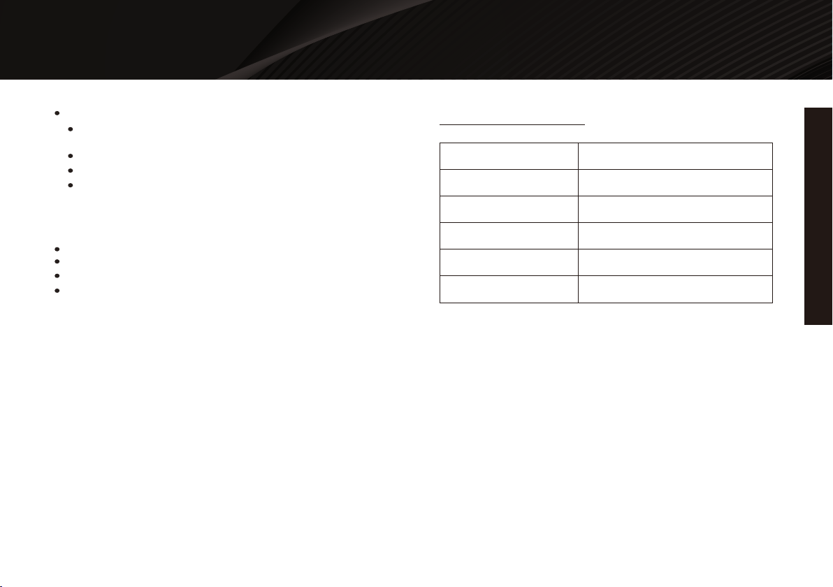
SPECIFICATIONS
Body Material
Overall Voltage
Maximum Power Usage
* Subject to change without notice, please contact your local
reseller for details.
Ducting / Venting
Protections
Filtration Type
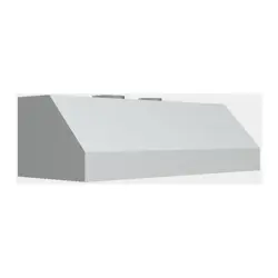
Stainless Steel, Brushed Finish
115V/60HZ
88W
6 inches, Round, Top Venting
Electrical Short Fuse
Stainless Steel Baffle Filter
INSTALLATION
FPO
INSTALLATION
5
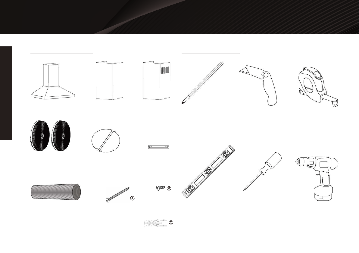
PARTS SUPPLIED TOOLS NEEDED
Range Hood Lower Chimney Upper Chimney
Marker or Pencil Utility Knife Measuring Tape
Level Flat & Phillips
Screwdrivers
Powered Drill
Charcoal Filter
(Sold Seperately)
Flexible Duct Tube
Range Hood Hook
Draft Damper Flaps Chimney
Mounting Bracket
Qty: 2 PCS
Qty: 9 PCS
Qty: 9 PCS

INSTALLATION
FPO
INSTALLATION
6
Vent system must terminate to the outside (roof orside wall).
DO NOT terminate the vent system in an attic orother enclosed
area.
DO NOT use 4”(10 cm) laundry-type wall caps.
Use metal/aluminum ducting only. Rigidmetal/aluminum ducting
is recommended.
Always keep the duct clean to ensure proper airflow.
Calculate the following figures before installation:
A distance of 26” to 30” is recommended betweenstove top and
the bottom of range hood.
26" is the lowest recommended for safe operation;30" is only
recommended for efficient operation, butcan be mounted higher.
It is recommended that the range hood be ventedvertically
through the roof through 6" (15 cm) orlarger round metal/alumi-
num vent work.
The size of the vent should be uniform.
Use no more than three 90° elbows.
For best results, attempt to make a minimum of24" (61 cm) of
straight vent between the elbows ifmore than one elbow is used.
DO NOT install two elbows together.
The length of vent system and number of elbowsshould be kept
to a minimum to provide efficientperformance.
The vent system must have a damper.If roof or wall cap already
has a damper, DO NOT use the supplied damper (if applicable).
Use duct tape or equivalent to seal all joints in thevent system.
Use caulking to seal exterior wall or roofopening around the cap.
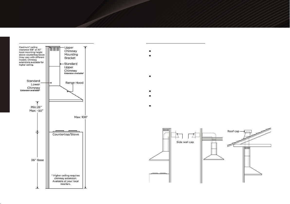
2 Due to different ceiling height configurationsf recommended
height may not be applicable.
1. Distance from the floor to the ceiling. *(less than108").
2.Distance between the floor to thecountertop/stove.
(Recommend 26ft to about30").
3.Distance between the countertop/stove to therange hood.
(Recommended26" to -30").
4.Height of range hood body and chimney coverscombined.
(Extension available1 2)
For the most efficient & quiet operation:
VENTING REQUIREMENTS
7
FPO
INSTALLATION
INSTALLATION
IMPORTANT
This range hood is factory set for venting through the roof or wall.
Vent work can terminate either through the roof or wall. To vent
through a wall, a 90° elbow is needed.
NEVER exhaust air or terminate duct work into spaces between
walls, crawl spaces, ceiling, attics orgarages. All exhaust must be
ducted to the outside.
Use metal/aluminum duct work only.
Fasten all connections with sheet metal screws and tape all joints
with certified duct tape or equivalent.
Use caulking to seal exterior wall or roof opening around the cap.
VENTING REQUIREMENTS VENTING METHODS
Horizontal Wall Venting
Option 1: Option 2:
Vertical Roof Venting
FPO
INSTALLATION
INSTALLATION
8
A minimum of 6" round (standard for this range hood) must be used
to maintain maximum airflow efficiency.
A flexible 6" round duct is provided for convenience and for use in
difficult installations, however alwaysattempt to use a smooth
metal/aluminum rigid type of ducting to maximize airflow efficiency.
ALWAYS, when possible, reduce the number or transitions and
turns. If long duct run is required, increaseduct size to 7" or 8". If a
reducer is used, install a long reducer instead of a pancake reducer.
Any reductionsof duct size will restrict and decrease airflow; to
maximize airflow flow efficiency place any reducers furthestaway
from any bends or transitions.
If turns or transitions are required, install them as evenly distanced as
possible, and as far away from therange hood as possible.
Please use the Duct Size Upgrade Calculator below to compute the
total available duct run when usingelbows, transitions and caps.
It is important to install the hood at the proper mounting height.
Hoods mounted too low is considered unsafeand could result in
heat damage and fire hazard; while hoods mounted too high are
harder to reach and willloose general effectiveness.
Minimum mount height between stove top to hood bottom should
be no less than 26''. Any less isconsidered unsafe and not recom-
mended.
Maximum mount height between stove top to hood bottom can be
higher than 30" is recommended to be thebest efficiency. (Extension
available*)
If available, also refer to stove top manufacturer's height clearance
requirements and recommended hoodmounting height above range.
Round ■ 6” minimum
Minimum duct size recommended is 6” round. Maximum duct
length recommend is 50 ft. Any duct length over 50 ft is
recommended to use a larger diameter duct size.
Survey the installation application and record the estimated
length of ducting required or used for that application. Record
the number of bends, angle of bends, and/or any transitional
pieces used. Each bend or transition will reduce air flow and
reduce the recommended duct length.
*Due to different ceiling height configurations, recommended height may
not be applicable.
Height & Clearance
minimumDuct Size Upgrade Calculator
Duct Deductions:
Each 90° bend 9 ft
Each 45° bend 5 ft
Each 6” to 3 1/4” x 10” transition 7 ft
Side wall cap with damper 1 ft
Roof Side wall cap with damper 1 ft
IMPORTANT
Minimum Duct Size:

FPO
9
INSTALLATION
INSTALLATION
To contact a qualified electrical installer.
To assure that the electrical installation is adequate and in
conformance with National Electrical Code,ANSI/NFPA 70 —
latest edition*, or CSA Standards C22.1-94, Canadian Electrical
Code, Part 1 and C22. 2No. 0-M91 - latest edition** and all local
codes and ordinances.
Provide a circuit protected power service; preferably a Ground
Fault Circuit Interrupter (f,G.F.C.I.f,): 120-volt,60 Hz, AC, with at
least 2-amps of available service.
Enlist a qualified electrician to ensure the range hood and
electrical lines are adequately grounded andproperly protected.
NEVER electrically ground to a gas pipe.
The range hood should be connected with a circuit breaker
protected power service.
Wire sizes (copper wire only) and connections must conform with the
rating of the appliance as specified on the model/serial rating label.
Wire sizes must conform to the requirements of the National Electrical
Code ANSI/NFPA 70 — latest edition*, or CSA Standards C22.1-94,
Canadian Electrical Code Part 1 and C22. 2 No. 0-M91 - latest
edition** and all local codes and ordinances. A U.L. - or C.S.A. - listed
conduit connector must beprovided at each end of the power supply
cable (at the range hood and at the junction box).
(1)90o bend, (1) 31/,x 10” transition, (2) 45° bends,(1)sidewall
cap with damper (with factory dampernot installed)
-9ft + -7ft + -5ft + -5ft + -1ft = -27ft
Deduct 27 ft from 50 ft, giving you 23 ft of available straight
ducting before it is recommended to upgrade your ducting size.
Remove grease filters from the hood.
Position the charcoal filters onto both side of the motor housing,
aligning the mounting points, turn until itlocks. Re-install baffle
filters.
Charcoal filters must be replaced after 120 hours of use (or
approximately every 2 to 3 months based on theaverage of 1 to
2 hours of daily cooking time). Available at your local resellers.
It is the customer’s responsibility:
1.
2.
3.
IMPORTANT: Observe all governing ordinances and local codes.
(Please consult with a qualified electrician for any electrical wiring)
IMPORTANT: Save this Installation Guide for future reference
and/or electrical inspector use.
Charcoal Filter Installation
Electrical Requirements
Duct Deduction Calculation Example:
NOTE:
OPTIONAL CHARCOAL FILTERS (SOLD SEPERATELY)

FPO
INSTALLATION
10
INSTALLATION
Copies of the standards listed may be obtained from:
*National Fire Protection Association
Batterymarch Park
Quincy, Massachusetts 02269
** CSA International
8501 East Pleasant Valley Road
Cleveland, Ohio 44131-5575
Familiarize yourself with the controls of the range hood by
readingthrough Range Hood Operations, Page 15.
Place the range hood on a flat, stable surface. Connect the
rangehood to a designated standard outlet (please refer the
product labelfor the suitable voltage of this unit) and turn on the
range hood.Verify all operations of the range hood by referring
to Range HoodOperations, Page 15.
Place all supplied parts and required hardware on a flat, stable
surface and verify the presence of all PartsSupplied listed on
Page 4.
Carefully remove the white plastic protective coat from the
chimney covers and range hood.
Determine whether your household ducting has a draft damper
system; only 1 draft damper system isrecommended for proper
efficiency.
Determine if you will be using the draft damper system on the
range hood. Install them onto the range hoodbefore starting the
installation. If you are using a draft damper system within the
household ducting, thedraft dampers do not need to be used
on the range hood.
Excessive Weight Require three or more persons to move and
install this range hood. Spinal or other bodily injuries could
occur if it is not followed.
1.
2.
3.
4.
5.
6.
WARNING
Preparation
Advanced Preparations:
FPO
INSTALLATION
11
INSTALLATION
Severe Injury
Rotating fan can cause severe injury. Stay clear of fan when
power is present.
WARNING
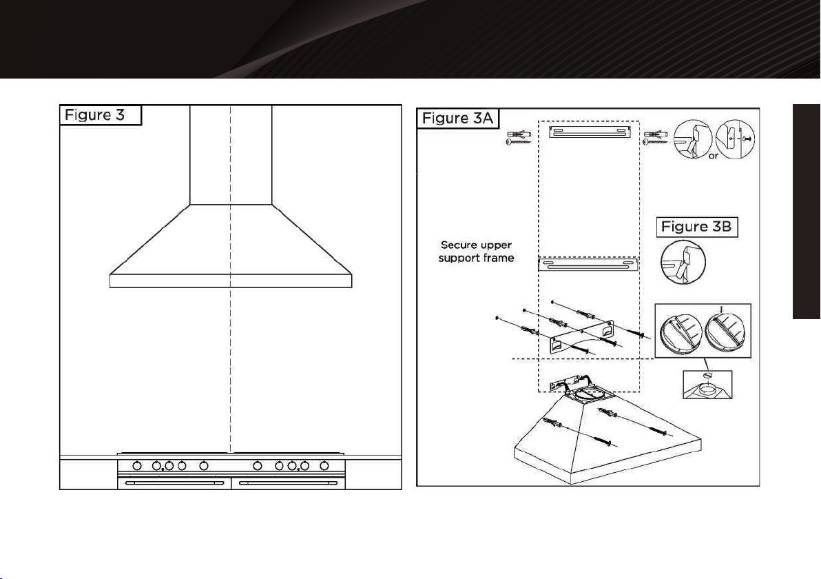
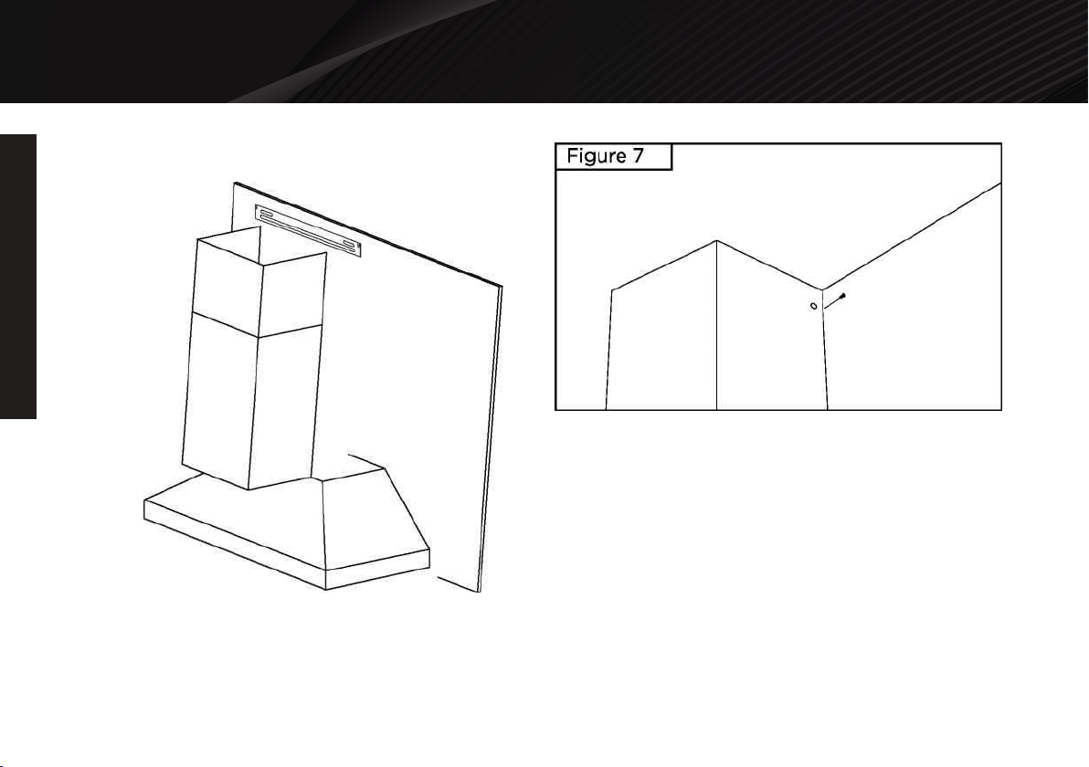
Determine and mark the center line on the wall where the range
hood will be installed. Make sure there isproper clearance within
the ceiling or wall for exhaust vent.
Due to the weight and size of this unit, please make sure that
the support system or framework being used isstable and
secure in the wall or ceiling.
Put a thick, protective covering over counter top, cook top or
range to protect from damage or dirt. Removeany hazardous
objects around the area when installing.
Mark the locations of the support mounting bracket holes,
ducting cutout (if used) and power supply cablecutout on the
wall or ceiling behind the chimney. Use drill and saber saw or
keyhole saw to cut openings forpower supply cable and ducting
(see Venting Requirements and Electrical Requirements, Pages
6 & 9 ).
If venting to the outside install vent system (see Venting
Methods, Page 7). Use caulking to seal exterior wallor roof
openings.
Disconnect main electrical supply, prepare and run electrical
wiring through ceiling or wall. Install a poweroutlet within
reaching distance of the range hood assembly. DO NOT restore
power until installation iscompleted.
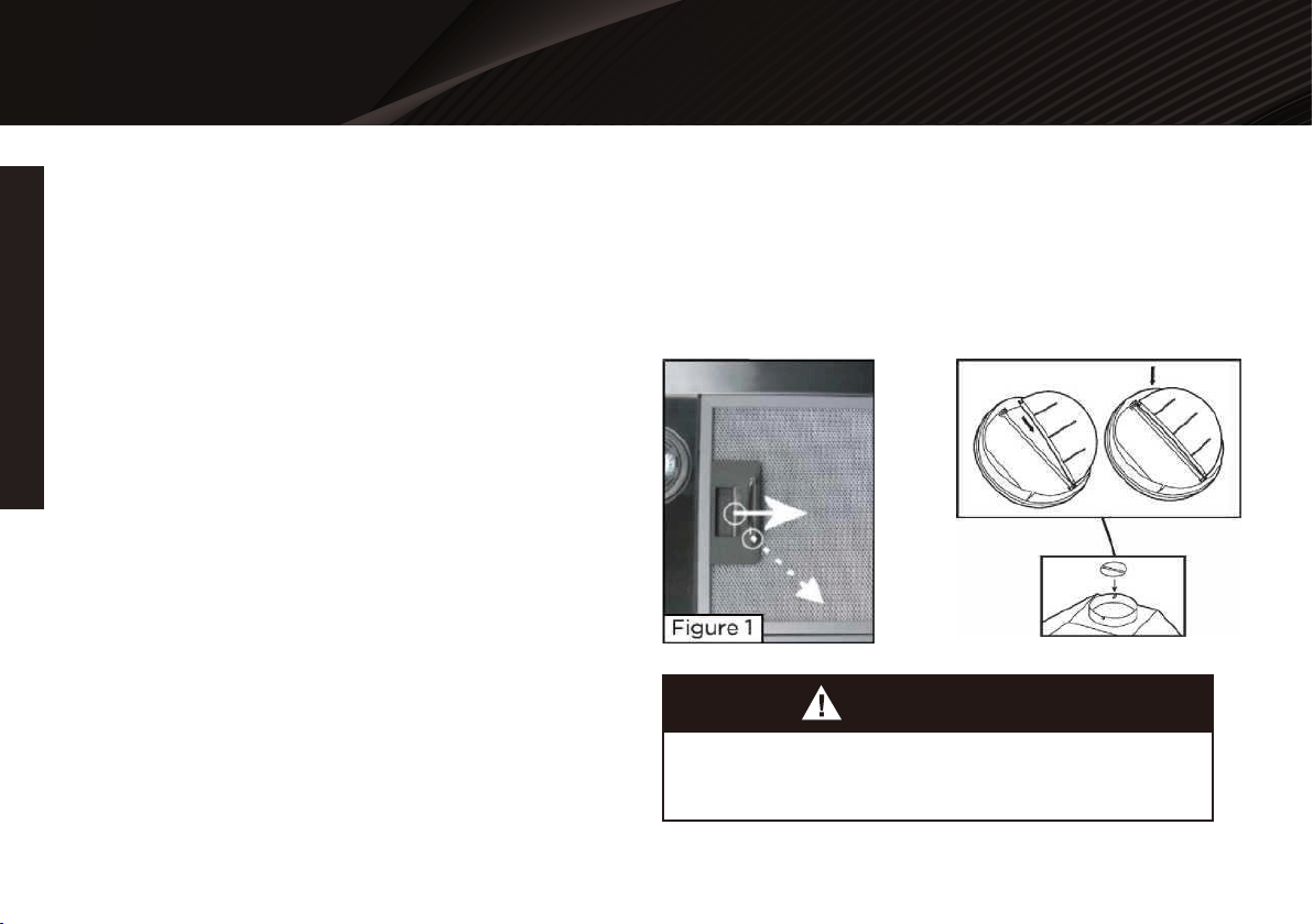
Disconnect power cord, remove the baffle filter by pressing on
the latch toward the direction of solid arrowwhile holding the
metal handle, gently pull the aluminum filter toward the direction
of dashed arrow as shownin Figure 1.
Set aside the baffle filters and grease cup until the range hood is
properly installed.
If the range hood comes with a glass canopy and has not already
been mounted to the hood, loosen the fourcanopy screws and
washers from the hood top, carefully place the canopy on the hood
top, and looselytighten the four canopy screws along with washers.
DO NOT put excessive pressure against the glass.
1.
8.
9.
2.
3.
4.
5.
5.
7.
Preparations:
NOTE: To avoid damage to your hoods prevent debris
from entering the vent opening.
FPO
INSTALLATION
INSTALLATION
12

Installation
FPO
INSTALLATION
INSTALLATION
13
Confirm your centerline and side measurements of each piece
of hardware. Use removable tape, pencil, orerasable marker to
mark your ideal installation.
Measure the distance between the stovetop and the bottom
edge of your range hood and then confirm therecommended
height of 26” to 30”*; Mark where the bottom of your range will
be installed.
*Due to different ceiling height configurations, this recommend-
ed height range may not be applicable.
1.
Confirm where you want your range hood installed
Double check your bracket is level, then mount thebracket on
the wall using the predrilled holes in theprevious step. Utilize all
provided hardware as it isdesigned as a system for a safe
installation. Ifdifferent hardware is used, ensure it meets or
exceedthe provided hardware. It is recommended to fastenas
many mounting points as possible into a wall stud,structural or
sub-frame for a secure result.
4.
Install the mounting bracket
With the help of an extra person, lift the range hoodbody and
hang it onto the mounting bracket. Themounting bracket is
designed to assist in mountingthe range hood and can only
support the range hoodtemporarily while checking for proper
alignment.After the hood is aligned and level, mark themounting
hole locations inside the cavity of the rangehood. Predrill those
marks, then mount the rangehood to the wall carefully to not
drill into any wires,cables or pipes.
5.
Position range hood body
The upper chimney is designed to be screwed ontothe chimney
mounting bracket and the lowerchimney is to be hung onto the
mounting bracket.Temporarily place the lower chimney cover
onto thehood and place the mounting bracket into place
andmark its installation holes. Remove the lower chimney
cover. The upper chimney must be flush against the wall, if
there is any crown molding or fixtures in the way, these items
must be modified. Measure the offset of the mounting bracket
screw hole locations from the top edge of the chimney cover.
Using that measurement, align the chimney bracket against the
wall and mark the screw hole locations. Ensure the chimney
and mounting brackets are level and centered.
6.
Mark chimney mounting bracket
Temporarily fit the range hood mounting bracket onto its
moutning position on the range hood assembly;note its
orientation and how it mounts on to the rangehood body.
Measure the distance from the bottomedge of the range hood
moutning bracket. Use thatmeasurement to mark the location
of the range hoodmounting bracket on your installation surface.
2.
Determine mounting bracket offset height
Using your marked location of the bottom of therange hood,
measure upward the distance of themounting bracket offset,
found in the previous step.Mark in the center of the installation
surface, this willbe your center screw location. Using the
bracketcentered on the wall with a level, mark the location
ofthe other screws. Using a powerdrill, pre-drill thescrew hole
locations ensuring you do not drill intoany power cables, wires
or pipes.
3.
Mark screw hole locations
FPO
INSTALLATION
INSTALLATION
14
FPO
INSTALLATION
INSTALLATION
15
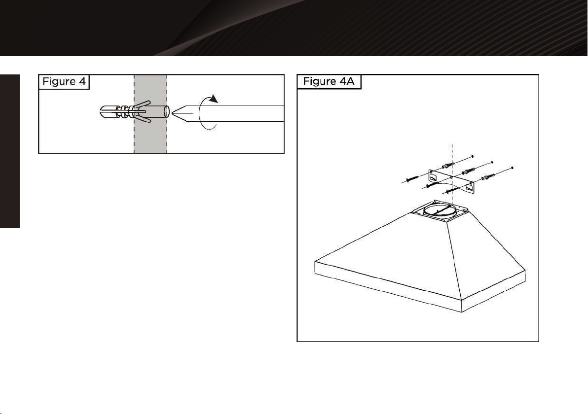
Predrill all mounting holes marked in the prior step.Install the
mounting bracket using the providedhardware. Wait to mount
the chimney and extensionuntil after step 9.
7.
Secure the mounting bracket
Install the duct tubing onto the household ducting firstand then
allow the duct to extend downward. Allowabout 6‘’ of extra
ducting past the duct mountingsurface of the range hood and
cut off any excess.Connect the flexible duct onto the ducting of
therange hood. Only use certified duct tapes, adhesives,fixtures
or hardware for all ducting installation aspermitted by local
codes. Install the power plug into acertified eletrical socket.
Ensure any excess wiring istied together or tucked away and
power is turned offwhile installing. Check that the area is free
fromdebris, then function test the range hood. It isrecommend-
ed to test the hood before and afterducting is installed. After
testing turn the power offbefore continuing.
8.
Install ducting, connect power and test
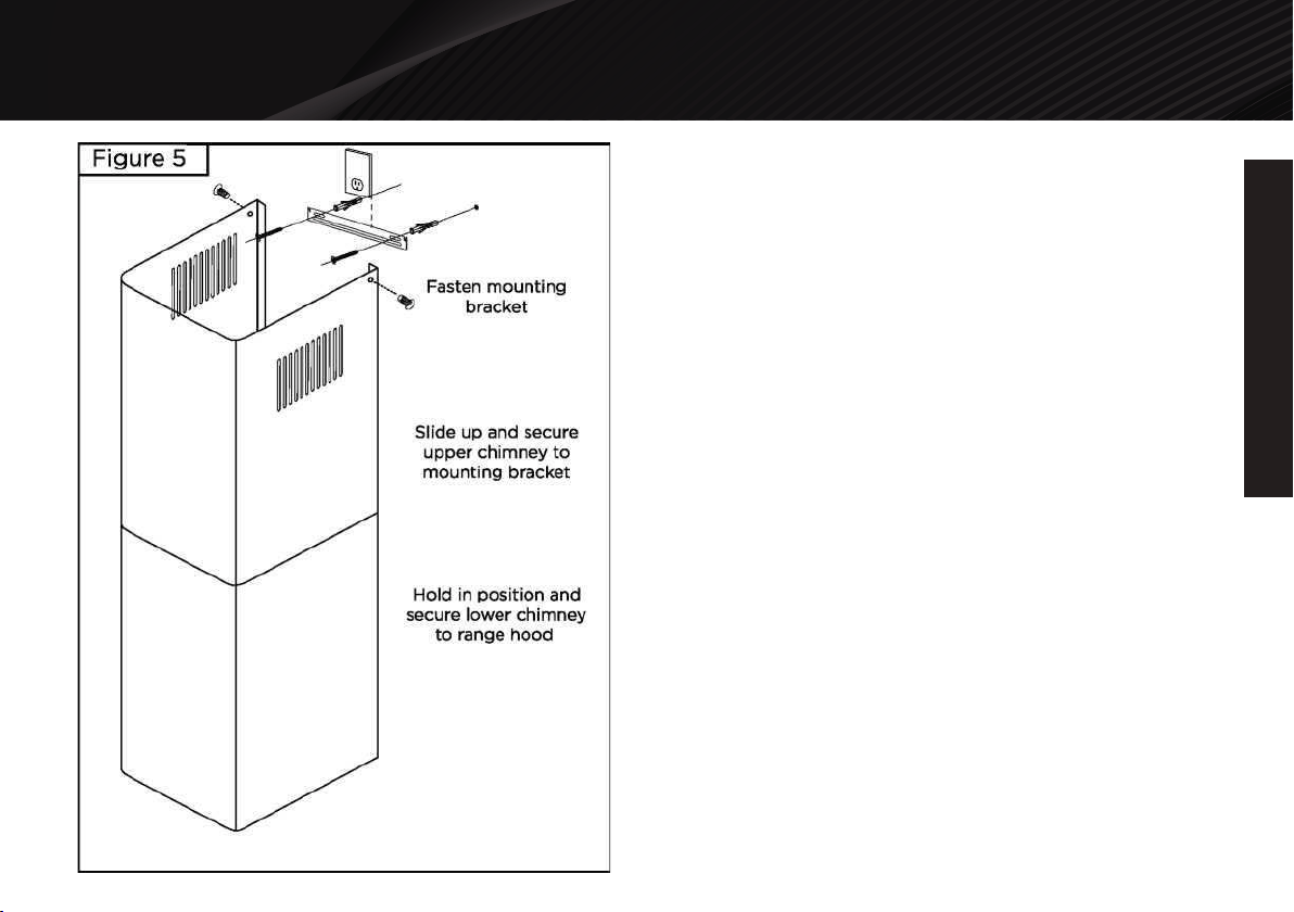
Fasten the upper chimney onto the upper chimneymounting
bracket using the supplied hardware; andthen hang the lower
chimney onto the lower chimneymounting bracket. Install the
lower chimney by flexingthe chimney apart, wrapping it over the
upperchimney, and then align the edges so that it hooksonto
the lower chimney mounting bracket.
9.
Install the chimney covers
16
OPERATION INSTRUCTIONS
WARRANTY REGISTRATION
INSTALLATION
INSTALLATION
To install the filters, postion the filters in the correct direction
with the latch facing down and angle the rear section (end
without the latch) into position, hooking the hanging tabs of the
filter into the correct spaces of the hood. Continue to push and
pivot the filter upward, while depressing the latch until it fits into
place. Release the latch again and push thelatch end of the
filter upward. Test that the filters are in place by slowly moving
your hands away, if it does not move, then the filter is installed
correctly. An additonal test to ensure the filters are properly
installed is to poke or grab at the edges of the filters and give
them a tug while keeping your hand below to catch them if they
are lose.
10.
Install the filters
After installing there will be fingerprints on your rangehood. To
remove finger prints use a soft cloth andwarm water. For
tougher spots, use warm water anda mild soap.
Lightly wipe away any left over water or moisture.ALWAYS
wipe in the direction of the grain of thebrushed stainless steel.
NEVER wipe in a circularmotion, against or across the grain of
the stainlesssteel. Use a specialized stainless steel cleaner
forthe toughest of stains or soils. Always spot test thecleaner in
a hidden spot and follow all manufacuturerinstructions on how
to use on the range hood.
11.
Cleaning the range hood
INSTALLATION
INSTALLATION
17
Figure 6
USE AND CARE
USE AND CARE
18
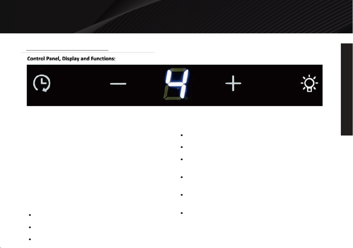
This button is used to turn ON the ventilation fan and also increase
the suction of the ventilation fan.
Increase Value Button
This button is used to turn OFF the ventilation fan and also
decrease the suction of the ventilation fan.
IDecrease Value Button
This button is used to activate the Delayed Power-Off Timer.
Delayed Power-Off Button
This button is used to activate and deactivate the Lighting System.
Light Button
Press and hold for 1-second the Increase Value Button to
activate the ventilation fan to the Low Speed.
Continue to press the Increase Button to increase the ventilation
fan speed to Medium and then High speeds.
Off, Low, Medium, High
Turning ON the ventilation fan and increasing the
suction
Press the Decrease Value Button to decrease the ventilation fan
speed.
Continue to press the Decrease Value Button to OFF to turn off
the ventilation system
High, Medium, Low, Off
Decreasing the suction and turning OFF the ventilation
fan
Press the Light Button to turn ON or OFF the lighting system
Turning ON and OFF the lighting system
From the ON position (ventilation system), press and hold for
1-second the Delayed Power-Off Button to activate theDelayed
Power-Off System
The Delayed Power-Off System is set to 5-minutes by default
Delayed Power-Off Button
Range Hood Operations
USE AND CARE
USE AND CARE
19
From the ON position (ventilation system), press and hold for
2-seconds the Delayed Power-Off Button to modify the Delayed
Power-Off System
Use the Increase Value Button and Decrease Value Button to
adjust the Delayed Power-Off System
The Delayed Power-Off System can be adjusted from 1 to 9
minutes.
Check if the range hood has been plugged in, make sure that all
power has been turned back ON, and all electrical wiring areprop-
erly connected. Swap out light bulb to working ones to determine
Whether it is caused by defective bulbs. See Replacing the light
bulbs on Page 20.
Adjusting the Delayed Power-Off System
Note: For all other inquiries, please contact us. Our
contact information can be found on the back cover
page.
Troubleshooting
If the range hood or light does not operate after
installation:
The blower might be jammed or scraping the bottom due
toshipping damage. Please contact us immediately.
The lights work but the blower isnot spinning, is stuck or
is rattling.
The range hood might not have been secured properly on to
theceiling or wall. Check with your installer.
The range hood vibrates when the suction is on:
Check that the duct sized used is at least 6".Range hood WILL
NOT function efficiently with insufficient duct size. For example: T
duct over 6" hole and loosely secured.
Check if duct is clogged or if damper unit (half-circular flapper)
isnot installed correctly or opening properly. A tight mesh on aside
wall cap unit might also cause restriction to the air flow.
The suction or fan seems weak:

20
OPERATION INSTRUCTIONS
WARRANTY REGISTRATION
USE AND CARE
USE AND CARE
Read and understand all instructions and warnings in this
manual before operating the appliance. Save these instructions
for future reference.
Always leave safety grills and filters in place. Without these
components, operating blowers could catch on to hair, fingers
and looseclothing.
NEVER dispose cigarette ashes, ignitable substances, or any
foreign objects into blowers
NEVER leave cooking unattended. When frying, oil in the pan
can easily overheat and catch fire. The risk of self combustion
ishigher when the oil has been used several times.
NEVER cook using "open” flames under the range hood.
Check deep-fryers during use: Superheated oil may be
flammable.
Operations:
* Subject to change without notice, please contact
your local reseller for details.
These slots/holes/openings are used to exhaust filtered air.
The saturation of greasy residue in the blower and filters may
cause increased inflammability. Keep unit clean and free of
greaseand residue build-up at all times to prevent possible
fires.
Filters must be cleaned periodically and free from accumulation
of cooking residue (see cleaning instructions on Page 19). Old
and worn filters must be replaced immediately.
DO NOT operate blowers when filters are removed. Never
disassemble parts to clean without proper instructions.
Disassembly is recommended to be performed by qualified
personnel only. Read and understand all instructions and
warnings in this manualbefore proceeding.
Cleaning:
Make sure the distance between the stove top and the bottomof
the hood is within 26” and 30” in distance. *Due to differentceiling
height configurations, recommended height may not be applica-
ble.
Reduce the number of elbows and length of duct work. Check if
all joints are properly connected, sealed, and taped.
Make sure the power is on high speed for heavy cooking.
Purpose of the slots/holes/openings near the top of
the upper chimney:
Note: For all other inquiries, please contact us. Our contact
information can be found on the back cover page.
The hood is not venting out properly:
USE AND CARE
USE AND CARE
21
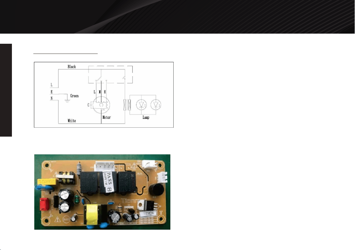
Touch Switch PCB
Electric Schematic

22
OPERATION INSTRUCTIONS
WARRANTY REGISTRATION
MAINTENANCE
MAINTENANCE
For optimal operation, clean range hood and all baffle/spacer/filter/
grease tunnel/oil container regularly. Regular care will help
preserve the appearance of the range hood.
SAFETY WARNING: Never put your hand into area
housing the fan while the fan is operating!
Clean periodically with hot soapy water and clean cotton cloth.
DO NOT use corrosive or abrasive detergent or steel
wool/scoring pads, which will scratch and damage the stainless
steel surface. For heavier soil use liquid degrease.
If the finish looks splotchy (stainless steel hood), use a stainless
steel cleaner to clean the surface of the hood. Use a dry soft
towel to dry the hood. CAUTION: Do not leave the cleaning
solution on the surface too 丨 ong as this may damage
the finish. Avoid getting cleaning solutions into or onto the
control panel, computer components, wires or wired plugs.
Always wipe/clean/polish in the same direction as the brushed
stainless steel finish. Never wipe against the grain.
After cleaning, you may use non abrasive stainless steel polish,
to polish and buff out the stainless luster and grain. Always
scrub lightly, with clean cotton cloth, and with the grain.
DO NOT allow deposits to accumulate or remain on the hood,
as they will become harder to clean, and may cause scratching
of the finish.
DO NOT use ordinary steel wool or steel brushes. Small bits of
steel may adhere to the surface and cause rusting.
Cleaning Exterior Surfaces:
The metal filters are intended to help filter grease, residue and
moisture from cooking.
They are required to be kept clean for performance and safety
concerns, and may require replacement ifneglected.
Filters should be cleaned after every 30 hours of use or sooner
depending on usage conditions.
Remove and clean by hand or dishwasher. NOTE: Some newer
dish detergents may cause marking orblackening of aluminum
metals, such as the mesh aluminum filters. Spray ''Formula
409®55 or equivalentdegreasing detergent and allow to soak if
heavily soiled. Rinse with warm water, allow the filters to dry
andthen and re-install before using hood.
IMPORTANT: Drain oil from oil containers before potential residue
overflow!
Cleaning Baffle Filter
Replacing Filters:
* Subject to change without notice, please contact your
local reseller for details.
Should filters wear out due to age and prolonged use, please
contact your local reseller for replacementfilters. Consider
preemptively purchasing an extra set of filters to store on hand,
or upgrading to stainlesssteel baffle filters.
Note: Also replace damaged filter that has punctured or broken
mesh, bent or broken frame.
DO NOT allow salt solutions, disinfectants, bleaches, or
cleaning compounds to remain in contact with stainless steel
for extended periods. Many compounds contain chemicals,
which may be damaging. Rinse with water after exposure and
wipe dry with a clean cloth.
Manintenance
MAINTENANCE
MAINTENANCE
23
Hazard of Burns!
Replacing The Light Bulb:
CAUTION: DO NOT touch the lights until switched OFF and cooled.
Note: Light settings are independent from other settings (including power-off delay) and lights has to be manually
turned on or off.
Note: The system saves user configurations, settings such as light, timer and vent (motor) speed will remain the
same the next time it is turned on.
Check the range hood tag for lamp specifications. Halogen
bulbs will not work on ’’LED” models (they willlightly pulse or
flash).
Before performing any task outside of basic operation, turn off
the power supply and/or unplug the unit.
Before attempting to handle the light bulbs, ensure the bulbs
are cool to the touch, including any adjacentworking surfaces.
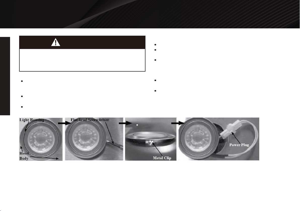
Replacing LED Light Fixture:
This range hood uses LED light fixture: 1.5W Max 12V LED
Make sure the range hood is unplugged or turn OFF breaker
and the lights are cool to touch.
Place a flat-head screwdriver between light housing and hood
body, gently pry up the light housingand search for the metal
clip. (Recorrmnended: use multiple layers of tape over the
screwdriverhead to prevent any scratching of the finish)
Apply force to the metal clip and pull out the light fixture.
Disconnect the power cable and discardthe old light fixture.
Reverse the steps to install a new halogen light fixture. Turn ON
breaker and range hood to test foroperation.
Light bulb become extremely hot when turned on. DO NOT touch
bulb until.
WARNING

24
OPERATION INSTRUCTIONS
WARRANTY REGISTRATION
WARRANTY
WARRANTY
For one year from the date of original purchase, your local reseller will
provide free of charge, non-consumable replacement parts or compo-
nents that failed due to manufacturing defects. Subject to the conditions
and limitations set forth below, your local reseller will, at its option, either
repair or replace any part of its products that prove defective by reason
of improper workmanship or materials. Repaired parts or replacement
products will be provided by your local reseller on an exchange basis,
and will be either new or refurbished to be functionally equivalent to new.
The consumer is responsible for all shipping costs. Consumable parts
not covered by this warranty include but not limited to: Light bulbs,
metal, aluminum and charcoal filters.
One Year Parts Warranty:
Consumable parts such as light bulbs, metal and charcoal filters.
The natural wear of finish, and wear due to improper mainte-
nance, use of corrosive and abrasive cleaning products, pads,
and oven cleaner products. Chips, dents or cracks due to
abuse, misuse, freight damage, or improper installation. Damage
of product caused by accident, fire, floods or act of God. The
manufacturer and/or distributor/reseller is not liable for, and does
not cover under warranty, any loss of properties or any costs
associated with removing, servicing, installing, or determining the
source of problems with this product.
This warranty is valid in the country of the original purchase at
retail. It is non-transferable and applies only to the original
purchaser and does not extend to subsequent owners of this
product. Any applicable implied warranties, including the
warranty of merchantability, are limited in duration to a period of
express warranty as provided herein beginning with the date of
original purchase at retail and, no warranties, whether express or
implied, shall apply to this product thereafter.
To obtain warranty service, you may contact your local reseller
from which you purchased this product. Please confirm the
terms of your local reseller's policies prior to contacting.
Typically, you must include product identification information,
including model number and serial number with a detailed
description of the problem you are experiencing. You must also
include proof of the date of original retail purchase as evidence
that the product is within the applicable warranty period.
What is Not Covered:
This warranty is extended to the original purchaser for products
purchased for ordinary home use.
Who is Covered:
Product damaged through negligence, improper installation, accident,
abuse, misuse, natural disaster, insufficient or excessive electrical
supply, abnormal mechanical or environmental conditions, or any
unauthorized disassembly, repair, modification, or failure to follow
installation instructions. When product is used commercially or other
than its intended purpose. Damaged because of improper connection
with equipment of other manufacturers. Repaired or modified by anyone
other than your local reseller's authorized agents. This limited warranty
also does not apply to any product on which the original identification
information has been altered, obliterated or removed, has not been
handled or packaged correctly or has been sold as second-hand.
This Warranty Will Be Voided When:
Warranty

WARRANTY
WARRANTY
25
Carefully inspect all items for damages before accepting delivery.
Note and picture any damages to the external box, contents or
item to the carrier and written on the freight bill or delivery receipt.
Request name and signature of the carrier's agent and keep copy
to support your claim. Upon acceptance of items, owner assumes
responsibility for its safe arrival. Report damages to the carrier and
file a claim immediately. Failure to do so may result in the denial of
your claim. The carrier will furnish you with necessary forms for filing
a claim.
Be sure to inspect the hood for damage and defects, and also
function test the hood before installation. Appearance flaws of the
hood found after installation and not affecting hood performance is
not covered under our warranty for returns or exchanges. Service
visits not covered under warranty.
Before Installation: Return for exchange or refund (please see
above for acceptable returns). After Installation: NO exchange or
refund.
If you need any assistance, please contact your local reseller.
Please have your order number and model of the range hood
ready. This information will help process your request or inquiry
more effectively.
If you need replacement parts, we recommend that you only use
genuine parts. Our accessories and parts are engineered and
designed specifically for this series of range hood, each is rigorous-
ly tested assuring the utmost in durability and reliability, providing a
factory match, factory-installed appearance and functionality
tailored to each individual range hood model.
The information in this document is subject to change without
notice, please contact your local reseller for updated details.
Damages caused during transit are not covered under our
warranty. Please contact us for additional help in filing your
insurance claim.
Please inspect contents of package(s) carefully upon receiving! We
must be notified of any damages and/or missing parts within five (5)
days upon your receipt of package(s). Claims will not be accepted
after five (5) days. NOTE: Items were thoroughly tested and
carefully packed in our factory before shipping.
Products must be returned in good working condition with ALL
original parts and documentation packed in ALL original cartons,
fillers and shipping cartons. A restocking fee of 15% will be charged
for all approved return(s). Exchanges or returns may not be
accepted if any packaging is missing.
The information in this document is subject to change
without notice, please contact your local reseller for
updated details.
Disclaimer
Contact
********************
Phone Number:*************


©2019 Galanz Americas Limited Company