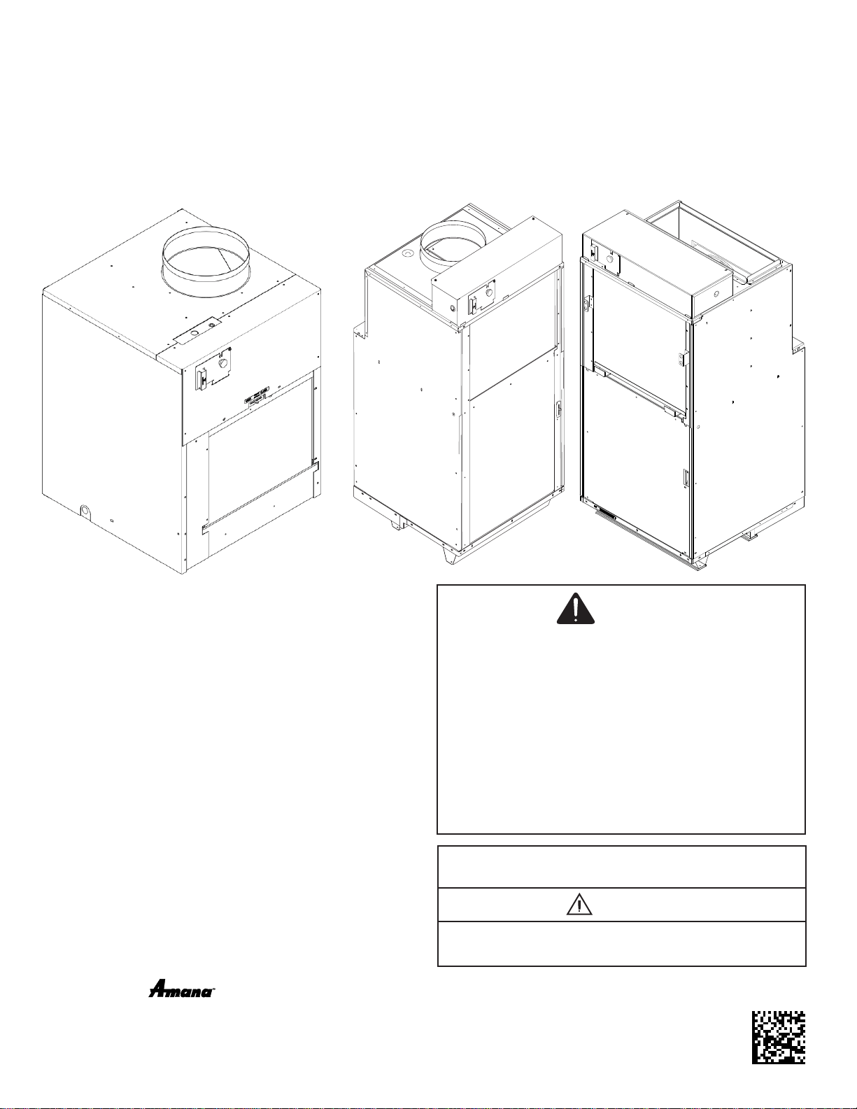
VTAC
Single Package Vertical Air Conditioning System
AVH 9,000-24,000 Btu/hr Installation Instructions
& Owner’s Manual
5151 San Felipe, Suite 500 • Houston, TX 77056 • www.amana-ptac.com
© 2014 - 2015, 2017 - 2020 Goodman Company, L.P.
is a registered trademark of Maytag Corporation or its related companies and is used under license
to Goodman Company, L.P., Houston, TX, USA. All rights reserved.
Only personnel that have been trained to install, adjust, service
or repair(hereinafter, “service”) the equipment specied in this
manual should service the equipment. The manufacturer will not
be responsible for any injury or property damage arising from
improper service or servide procedures. If you service this unit,
you assume responsibility for any injury or property damage
which may result. In addition, in jurisdictions that require one or
more licenses to service the equipment specied in this manual,
only licensed personnel should servise the equipment.
Improper installation, adjustment, servicing or repair of the
equipment specied in this manual, or attempting to install,
adjust, service or repair the equipment specied in this manual
without proper training may result in product damage, property
damage, personal injury or death.
WARNING
WARNING
PROP 65 WARNING
FOR CALIFORNIA CONSUMERS
Cancer and Reproductive Harm -
www.P65Warnings.ca.gov
0140M00513-A
ATTENTION INSTALLING PERSONNEL
As a professional installer you have an obligation to know
the product better than the customer. This includes all
safety precautions and related items.
Prior to actual installation, thoroughly familiarize yourself
with this Instruction Manual. Pay special attention to all
safety warnings.
Often during installation or repair it is possible to place
yourself in a position which is more hazardous than when
the unit is in operation.
IO-914
07/2020
1
Important Note to the Owner
This manual is to be used by qualied, professionally
trained HVAC technicians only. Goodman does not assume
any responsibility for property damage or personal injury
for improper service procedures or services performed by
an unqualied person.
IMPORTANT NOTES:
Your warranty certicate is also supplied with the unit.
Read the warranty carefully and note what is covered.
Keep the warranty certicate in a safe place, so you
can nd it, if necessary.
Before using this manual, check the serial plate for
proper model identication.
THE INSTALLATION AND SERVICING OF THIS
EQUIPMENT MUST BE PERFORMED BY
QUALIFIED, EXPERIENCED TECHNICIANS ONLY.
Due to policy of continual product improvement, the
right is reserved to change specications and design
without notice.
Remember, it is your responsibility to install the product
safely and to know it well enough to be able to instruct a
customer in its safe use.
Safety is a matter of common sense...a matter of thinking
before acting. Most dealers have a list of specic good
safety practices...follow them.
The precautions listed in this Installation Manual are
intended as supplemental to existing practices. However,
if there is a direct conict between existing practices and
the content of this manual, the precautions listed here take
precedence.
Important Note to the Servicer
Read this manual and familiarize yourself with the specic
items which must be adhered to before attempting to
service this unit. The precautions listed in this Installation
Manual are intended as supplemental to existing practices.
However, if there is a direct conict between existing
practices and the content of this manual, the precautions
listed here take precedence.
RECOGNIZE THIS SYMBOL
AS A SAFETY PRECAUTION.
WARNING
HIGH VOLTAGE
DISCONNECT ALL POWER BEFORE SERVICING
OR INSTALLING THIS UNIT. MULTIPLE POWER
SOURCES MAY BE PRESENT. FAILURE TO DO SO
MAY CAUSE PROPERTY DAMAGE, PERSONAL
INJURY OR DEATH.
Contents
Electrical Data ....................................................................2
Supply Air Flow Data...........................................................3
Control.................................................................................3
VTAC Required Minimum Clearances.................................3
Installation Overview and Dimensional Data ......................4
Closet View..........................................................................4
Exterior Wall Adapter Installation.........................................5
Louver Installation................................................................6
Final Wall Adapter and Architectural Louver Installation.....7
Primary Drain Connection and Location..............................8
Indoor Return Air Grille and Ductwork Installation.............12
Ductwork............................................................................12
Chassis Installation............................................................12
Remote Thermostat and Low Voltage Control
Connection........................................................................13
Final Installation Checklist.................................................14
Chassis Operation.............................................................14
Chassis Final Connections................................................14
Service & Warranty............................................................14
Routine Maintenance.........................................................15
Warranty............................................................................15
Electronic Control Error Code Diagnostics and
Test Mode..........................................................................15
ERROR CODES AND ALARM STATUS............................16
Obtaining Service...............................................................20
Drain Pan Installation AVH18 & AVH24...............................8
1
Electrical Data
Electrical Requirements
Wire Size Use ONLY wire size recommended for
single outlet branch circuit.
Fuse/Circuit
Breaker
Use ONLY type and size fuse or HACR
circuit breaker indicated on unit’s rating
guide. Proper over current protection
to the units is the responsibility of the
owner.
Grounding Unit MUST be grounded from branch
circuit to unit, or through separate
ground wire provided on permanently
connected units. Ensure that branch
circuit or general purpose outlet is
grounded.
Wire Sizing Use recommended wire size given in
tables and install a single branch circuit.
All wiring must comply with local and
national codes.
NOTE: Use copper conductors only.
Electrical Rating Table
NOTE: Use copper conductors ONLY. Wire sizes are per NEC.
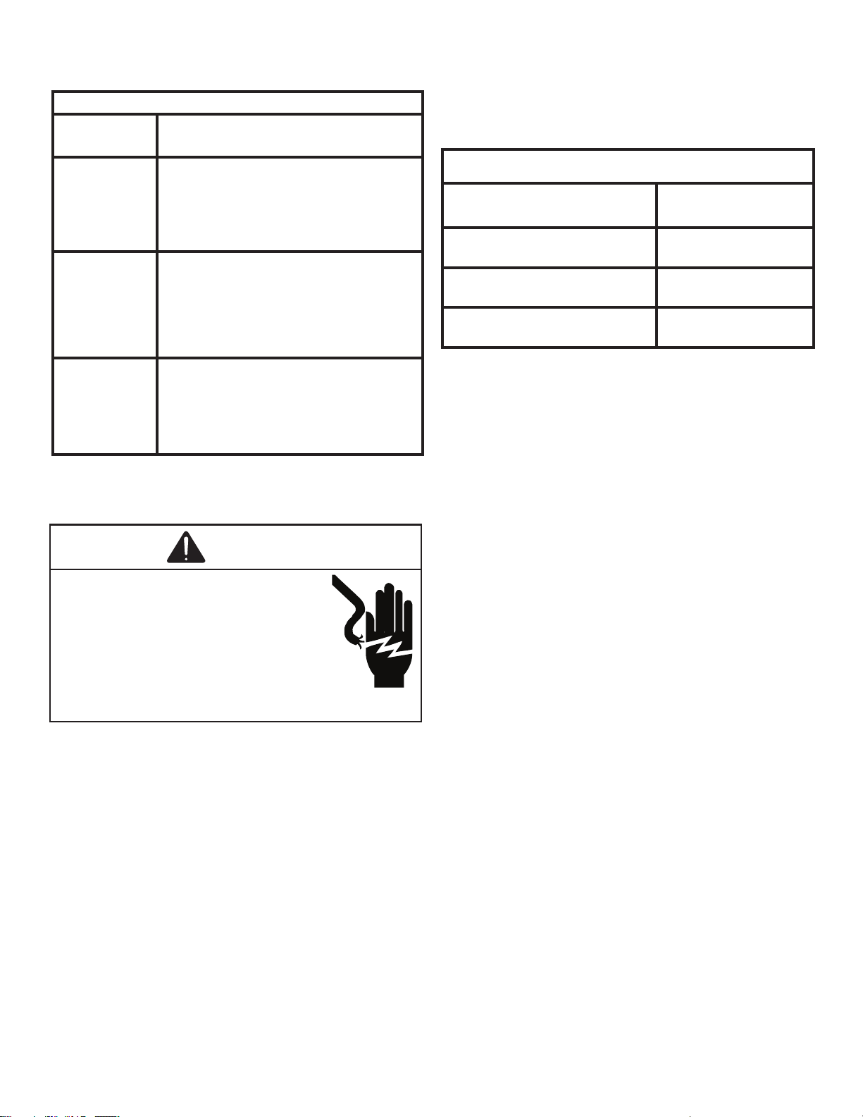
Recommended Branch Circuit Sizes*
Nameplate Maximum Circuit
Breaker Size
AWG Wiring Size**
15A 14
20A 12
30A 10
AWG - American Wire Gauge
* Single circuit from main box.
** Based on 100’ or less of copper, single insulated conductor at
60˚ C
NOTE: All 230/208 chassis must be hard wired with a properly sized breaker. See unit nameplate for specic electrical requirements.
Use HACR type breakers to avoid nuisance trips. All eld wiring must be done in accordance with NEC and local codes. It is the
installer’s responsibility to ensure that the electrical codes are met.
WARNING
HIGH VOLTAGE
DISCONNECT ALL POWER BEFORE SERVICING
OR INSTALLING THIS UNIT. MULTIPLE POWER
SOURCES MAY BE PRESENT. FAILURE TO DO SO
MAY CAUSE PROPERTY DAMAGE, PERSONAL
INJURY OR DEATH. DO NOT SERVICE THIS UNIT
WITHOUT FIRST SHUTTING OFF POWER TO THE
UNIT FROM THE CIRCUIT BREAKER AND/OR
REMOVING THE UNIT CORD SET PLUG FROM
THE WALL OUTLET.
2
Supply Air Flow Data
Indoor CFM & External Static Pressure
Indoor air ow may be determined by measuring the
external static pressure (ESP) of the duct system using an
inclined manometer or magnahelic gauge and consulting
the above chart to derive actual air ow. Under no
circumstances should the small chassis VTAC equipment
be operated at an external static pressure in excess of .3”
W.C. Operation of the VTAC under these conditions will
result in inadequate air ow, leading to poor performance
and/or premature component failure.
Control
For LOW speed only operation, connect the fan output
terminal from the thermostat to the GL terminal of the
electronic control.
For HIGH speed only operation, connect the fan output
terminal from the thermostat to the GH terminal of the
electronic control.
For thermostats with two-speed capability, connect the
LOW speed output to the GL terminal and the HIGH speed
output to the GH terminal.
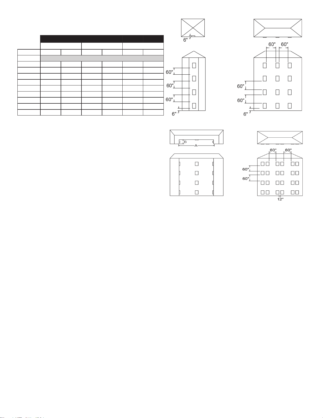
VTAC Required Minimum Clearances
Building Exterior Unit Opening Requirements
VTAC units must be installed on an outside wall. Conned
spaces and/or covered areas should be avoided. Units
must be installed no closer than 12” apart when two units
are side by side. If three or more units are to operate next
to one another, maintain a minimum of 60” between units or
pairs of units (Figure B). If more than two units are sharing
a oor with adjacent, outset units, a minimum distance of
64” must be kept between units (Figure C). Also, a vertical
clearance of 60” must be maintained (Figure A) between
units. Units installed on the bottom oor must be mounted
at least 6” off of the ground.
Figure A Figure B
Figure C Figure D
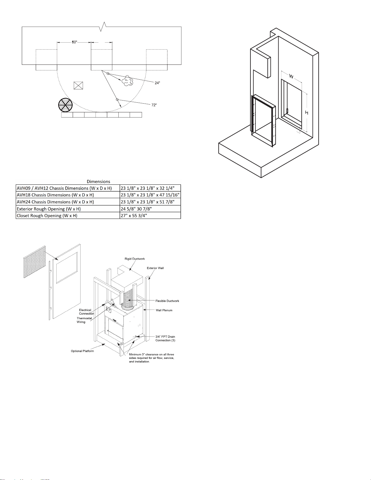
Grill Clearance Requirements
Where obstructions are present use the following
guidelines for proper spacing from the VTAC exterior
louvered grill. Amana recommends that ALL obstructions
are a minimum of 72” from the exhaust.
For minor obstruction(s) such as lamp poles or small
shrubbery, a clearance of 24” from the outdoor louver must
be maintained.
For major obstructions such as a solid fence, wall, or other
heat rejecting devices like a condensing unit, a minimum
distance of 72” must be kept.
3
Model
AVH09/AVH12 AVH18 AVH24
Fan Speed Low
High
L
ow
High
Low
High
ESP (“)
SCFM
0.0” 470
520 730 800 755 805
0.05”
460
510 670 735 700 750
0.10”
430
490 630 675 660 700
0.15”
410 470 595 640 615 665
0.20”
360 440 550 600 575 625
0.25”
310
400 505 550 525 580
0.30”
260 350 455 500 485 540
0.35”
-- -- 400 445 450 500
0.40”
-- -- 345 400 415 465
BUILDING
24"
POLE
SHRUB
FENCE
MAJOR OBSTRUCTIONS
OUTDOOR
CONDENSING
UNIT
VTAC VTAC
VTAC
NOTE: The example pictured above is for reference only
and does not represent all possilbe installations.
Installation Overview and Dimensional Data
Closet View
NOTE: It is recommened that 6” of clearance is
provided on the side where the primary condensate is
plumbed.
3/4”
Exterior Wall Adapter Cut-Out
Dimensions (W x H): 24 5/8” x 30 7/8”
NOTE: The distance between the rough opening
and the nished oor/platform must be 3/4”. If the
installation will utilize an auxiliary drain pan, it may not
exceed 3/4” in height.
4
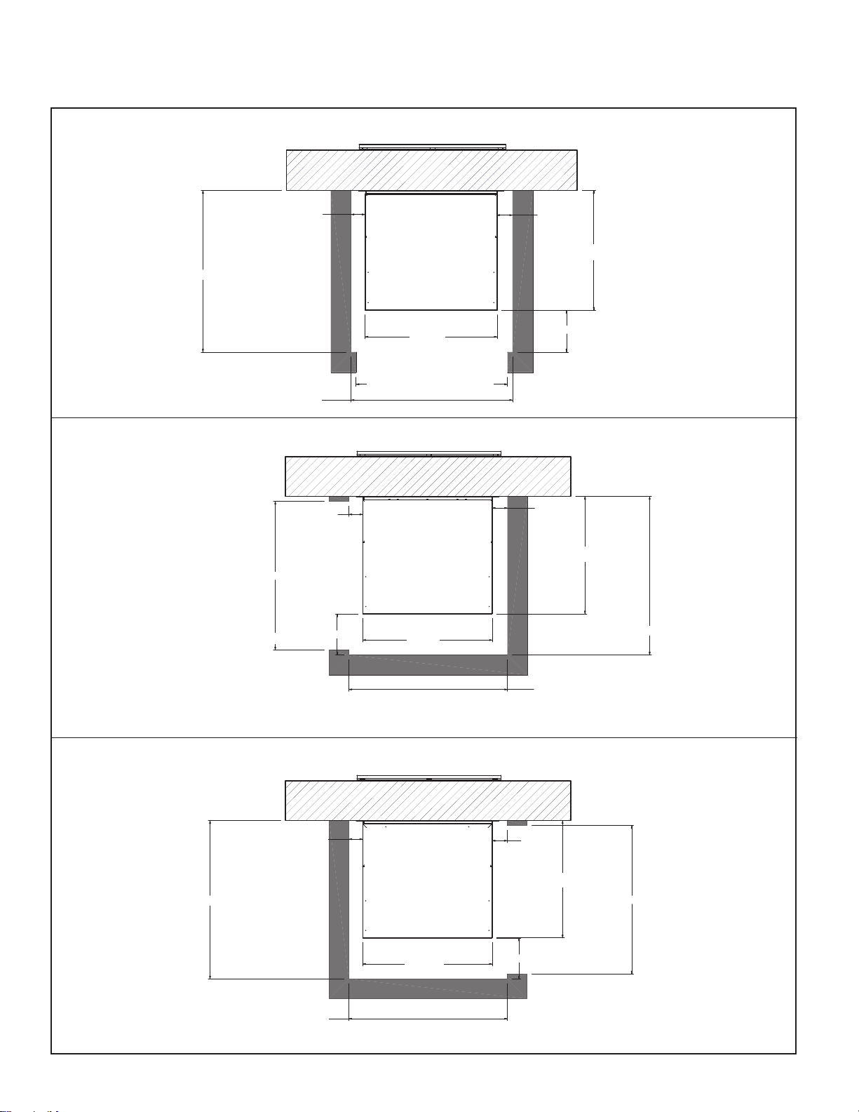
)URQW,QVWDOODWLRQ7RS9LHZ
/HIW,QVWDOODWLRQ7RS9LHZ
5LJKW,QVWDOODWLRQ7RS9LHZ
3
23 1/8"
26 1/8"
CLOSET INSTALLATIONS
5
Access Door Cutout = 27"
Min. 3" Required
23 1/8"
23 1/8"
30 5/8" ( Min. Required Inside Closet Dimension )
23 1/8"
Access Door Cutout = 27"
23 1/8"
23 1/8"
30 5/8" ( Min. Required Inside Closet Dimension )
Access Door Cutout = 27"
29 1/8" ( Min. Required Inside Closet Dimension )
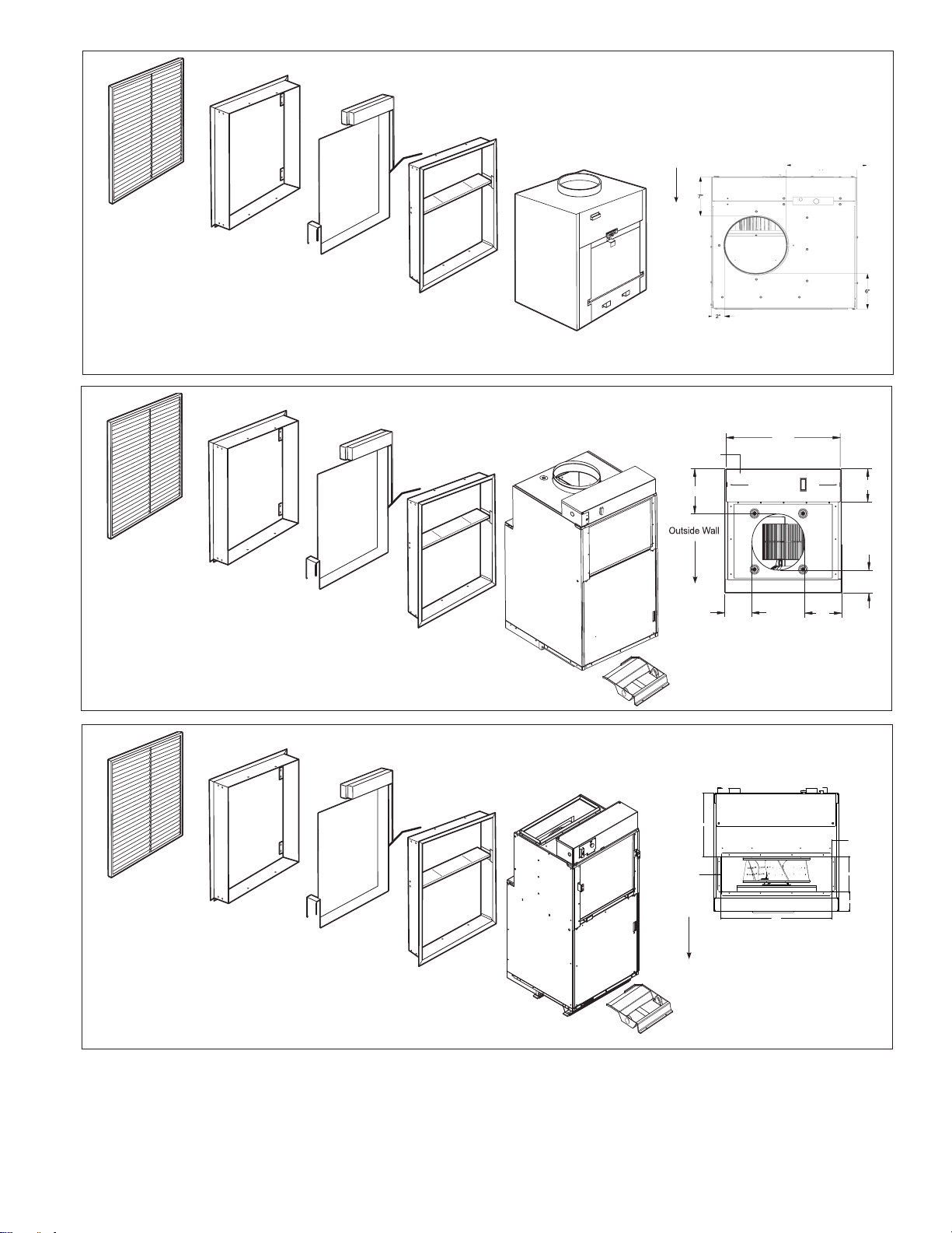
Architectural Grille
AVAGK01xx
Exterior/
Outside Wall
Part B
Inside
Wall Adapter
Unit
Part A
Outside
Wall Adapter
Applicable Models
AVH09xxxxxxxx
AVH12xxxxxxxx
AVEWA05-08A = 5 1/2" - 8" D x 24 1/8" W x 30 3/8" H
AVEWA08-14A = 8" - 14" D x 24 1/8" W x 30 3/8" H
Architectural Grille
AVAGK01xx
Exterior/
Outside Wall
Part B
Inside
Wall Adapter
Unit
Part A
Outside
Wall Adapter
Applicable Models
AVH18xxxxxxxx
AVEWA05-08A = 5 1/2" - 8" D x 24 1/8" W x 30 3/8" H
AVEWA08-14A = 8" - 14" D x 24 1/8" W x 30 3/8" H
Large Chassis Unit
(Unit height 47”)
Filter (14” x 20”)
Small Chassis Unit
(Unit height 32”)
Filter (14” x 20”)
AVDK18-2401B drain pan
required (Sold & Shipped
Separately)
Architectural Grille
AVAGK01xx
Exterior/
Outside Wall
Part B
Inside
Wall Adapter
Unit
Part A
Outside
Wall Adapter
Applicable Models
AVH24xxxxxxxx
AVEWA05-08A = 5 1/2" - 8" D x 24 1/8" W x 30 3/8" H
AVEWA08-14A = 8" - 14" D x 24 1/8" W x 30 3/8" H
24k Chassis Unit
(Unit height 52”)
Filter (18” x 20”)
AVDK18-2401B drain pan
required (Sold & Shipped
Separately)
Outside
Wall
7"
2"
6"
control box
22
5
/
16
"
8
3
/
8
"
6
3
/
16
"
4
3
/
16
"
7
3
/
16
"
5
5
/
16
"
3 55/64
"
1 1/2
"
12 19/64
"
1 1/2
"
6 55/64
"
20 5/8
"
Outside
Wall
11”
10"
10"
6
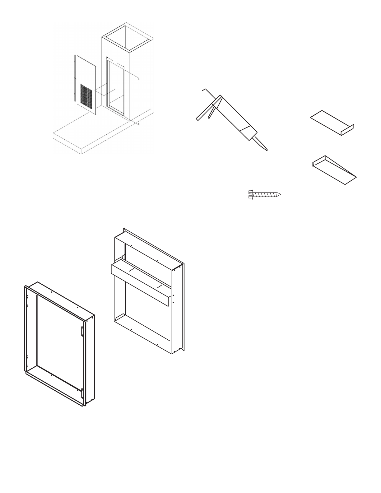
Return Air Access Door Wall Cut-Out
Dimensions (W x H): 27” x 55 3/4”
Wall Adapter Installation
Parts included in Wall Adapter Kit:
• Outside Adapter Half (Part A)
• Inside Adapter Half (Part B)
A
B
Field Supplied Parts:
Sealant, attachment screws, and ashing
are eld supplied. Silicone sealant is recommended.
AVEWA05-08A adjust for walls up to 4”- 8” thick.
AVEWA08-14A adjust for walls up to 8” - 14” thick
All installations are similar.
Step 1 - Outside Wall Adapter Half
NOTE: The Wall Adapter is not designed to carry any
structural load. A load bearing header must be built
above the rough opening.
1. Prepare the rough opening. The rough opening
should be lined with metal or wood. The Wall
Adapter will warp if sealed against concrete or
brick.
2. Dry t the outside Wall Adapter half into the rough
opening and check the t and level.
3. Remove the outside Wall Adapter half, ash the
rough opening to ensure proper t and level.
4. Pre-installing the exterior louver (AVAGK01CB) as
shown above is optional (See Page 6).
5. Apply sealant to the outside Wall Adapter half and
insert into the rough opening to ensure a water-tight
seal. Ensure that the outside Wall Adapter half is
securely attached to the framed opening.
7
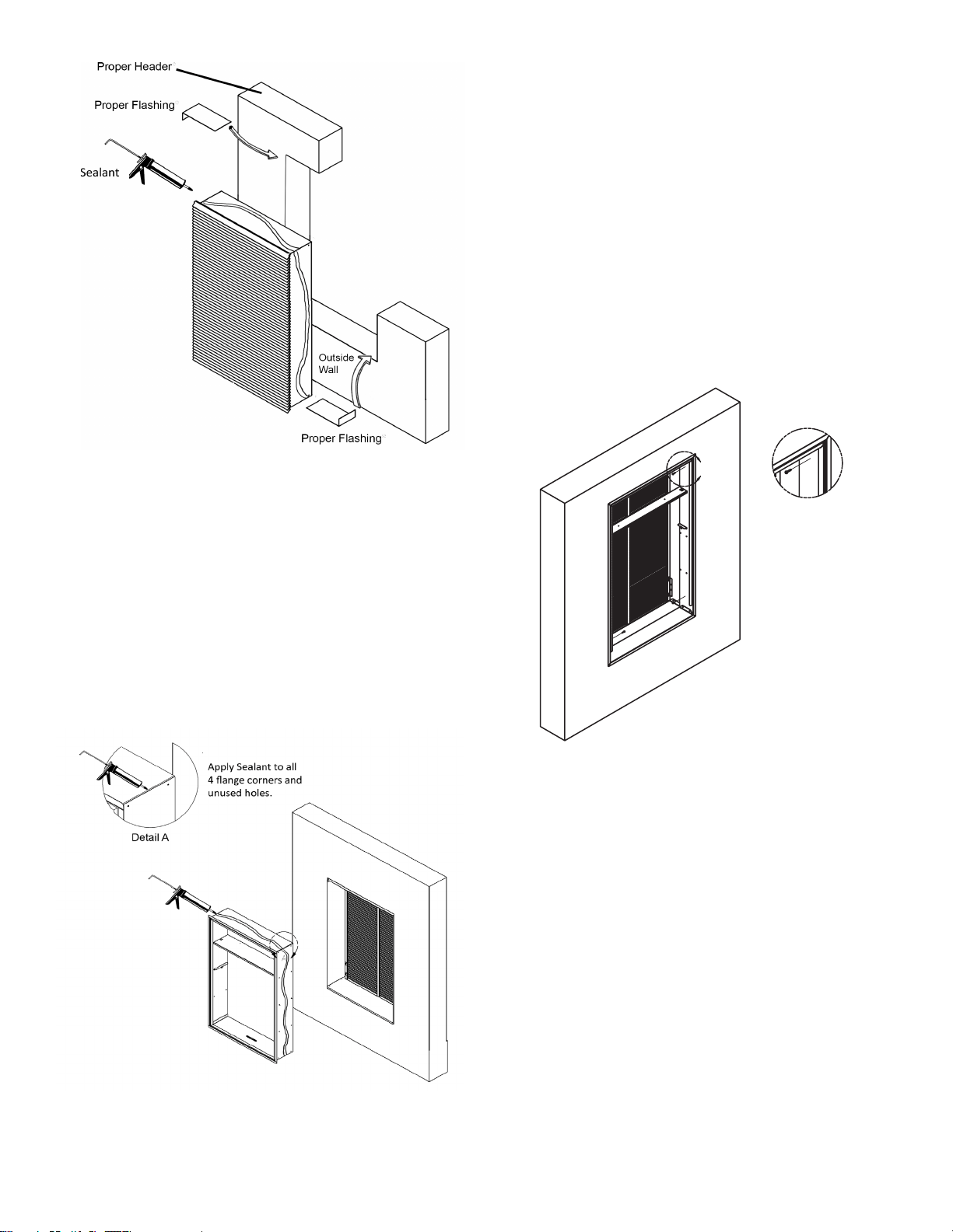
Step 2 - Inside Wall Adapter Half
1. Apply sealant to all 4 ange corners and unused
holes. See Detail A.
2. Flash the inside of the rough opening to ensure the
proper t and level.
3. Insert inside Wall Adapter half (Part B) into outside
Wall Adapter half (Part A). Ensure that Part A does
not back out of the rough opening.
4. Remove the inside Wall Adapter half.
5. Apply sealant to the outside Wall Adapter half and
insert into the rough opening to ensure a water-tight
seal.
Step 3 - Inside Wall Adapter (cont.)
NOTE: Do not place any screws, fasteners, or
penetrating holes through the top or bottom of the Wall
Adapter assembly.
1. Drill pilot holes on the interior of the inside Wall
Adapter half (Part B) as show in Detail B. Pilot holes
should be located approximately 4” from the top and
bottom of the inside Wall Adapter half, on both the
left and right sides.
2. Install fasteners through each pilot hole. Fastener
must pass through both Part A and Part B. If the
inside and outside Wall Adapter halves do not
overlap at fastening point, be certain to drill extra
holes where needed to secure both Part A and Part B
to the rough opening.
B
Detail B
Louver Installation
Installation of the louver PRIOR to Wall Adapter
installation
1. Hold the louver up to the outside Wall Adapter half
(Part A) and line up the louver top with the very top
edge of the ¾” ange.
2. Line up the Wall Adapter holes with the threaded
holes in the louver and securely tighten
fasteners.
8
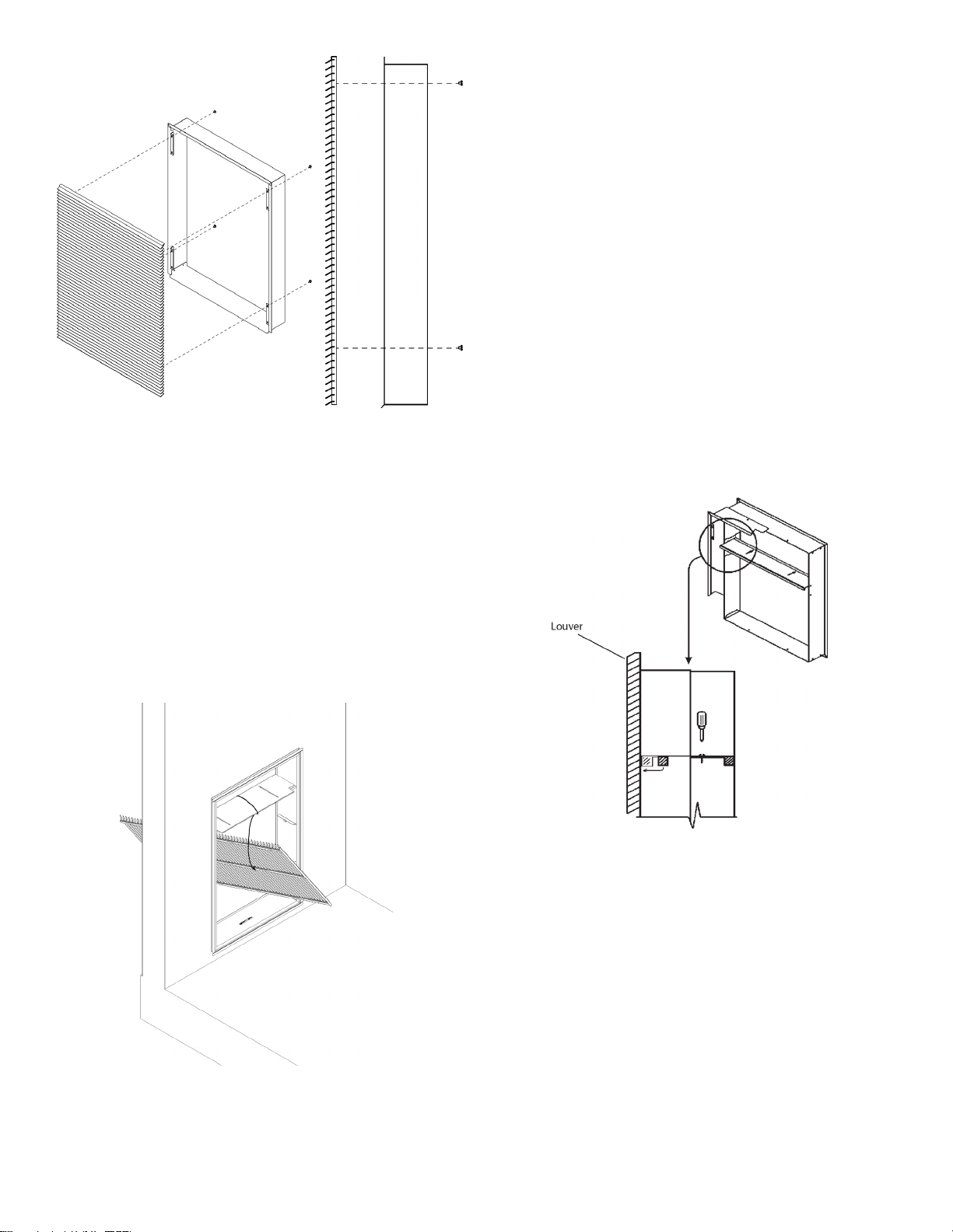
Installation of the louver AFTER the installation of
Wall Adapter on elevated oors
From the interior of the utility closet:
1. Tie a rope or tether to the architectural louver and the
divider in the Wall Adapter to prevent it from falling if
dropped.
2. Turn the louver sideways and push the louver out
below the divider in the Wall Adapter.
3. Pull the louver back against the Wall Adapter and
align the holes.
4. Insert and tighten all eight provided fasteners. When
the louver is secured, remove the safety tether.
Final Wall Adapter and Architectural Louver
Installation
NOTE: Ensure that the weather strip is undamaged and
provides a continuous seal around the inner perimeter
of the Wall Adapter.
Apply silicone grease or other non-petroleum-based
lubricants to the weather strip to enhance the sealing
capability of the weather strip and ease installation of the
air conditioner chassis.
1. Loosen the two set screws located on the top side of
the divider.
2. Slide the top part of the divider toward the outside
until the sealing strip makes contact with the exterior
louver.
3. Tighten the set screws to complete the
adjustment.
NOTE: Let all ashing cure completely before installing
the chassis.
9
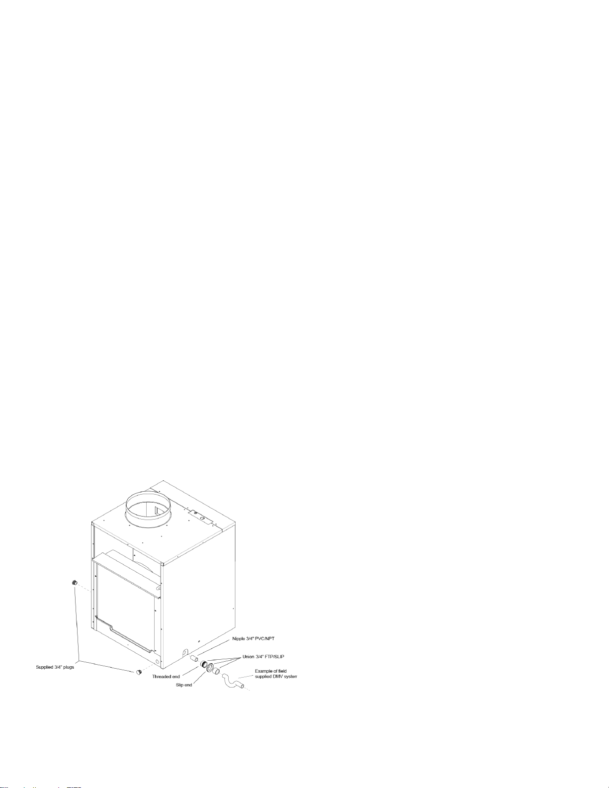
Primary Drain Connection and Location
For AVH09 & AVH12 Units only
NOTE: Failure to follow the following procedures may
result in serious property damage. A field supplied
secondary condensate pan or P-trap may be required.
Check with local codes. In case of drainage system
blockage, the unit base will allow excess water to flow
out of the unit through the wall adapter and the
architectural louver. It is critical to ensure that the
drainage path is not blocked or obstructed in any way
during the installation.
1. The supplied drain kit must be connected to one of
the three (left, right or rear) 3/4” FPT connections
on the unit base pan. Use of rear fitting without
connection to DWV system (drain, waste, vent)
may result in staining of the outside wall.
2. Insert the provided 3/4” nipple into the determined
connection using eld-supplied Teon tape or pipe
joint compound.
3. With the slip end of a 3/4” union, connect to the
nipple with Teon tape or pipe joint compound.
4. Hand-tighten all ttings to prevent damage to unit or
ttings.
5. Install a eld-supplied drain system to the slip end
of the union. A trap is recommended and drain
connections should be connected to building DWV
system. Pitch the drain line of a 1/4” downward slope
for every foot (1’) of lateral horizontal run to the
DWV.
6. Plug the two unused connection ports with the two
provided 3/4” pipe plugs with eld-supplied Teon
tape or pipe joint compound. Hand tighten to prevent
damage to the unit or ttings. Do not thread metal or
copper pipe ttings directly into unit.
7. Check the system for leaks.
10
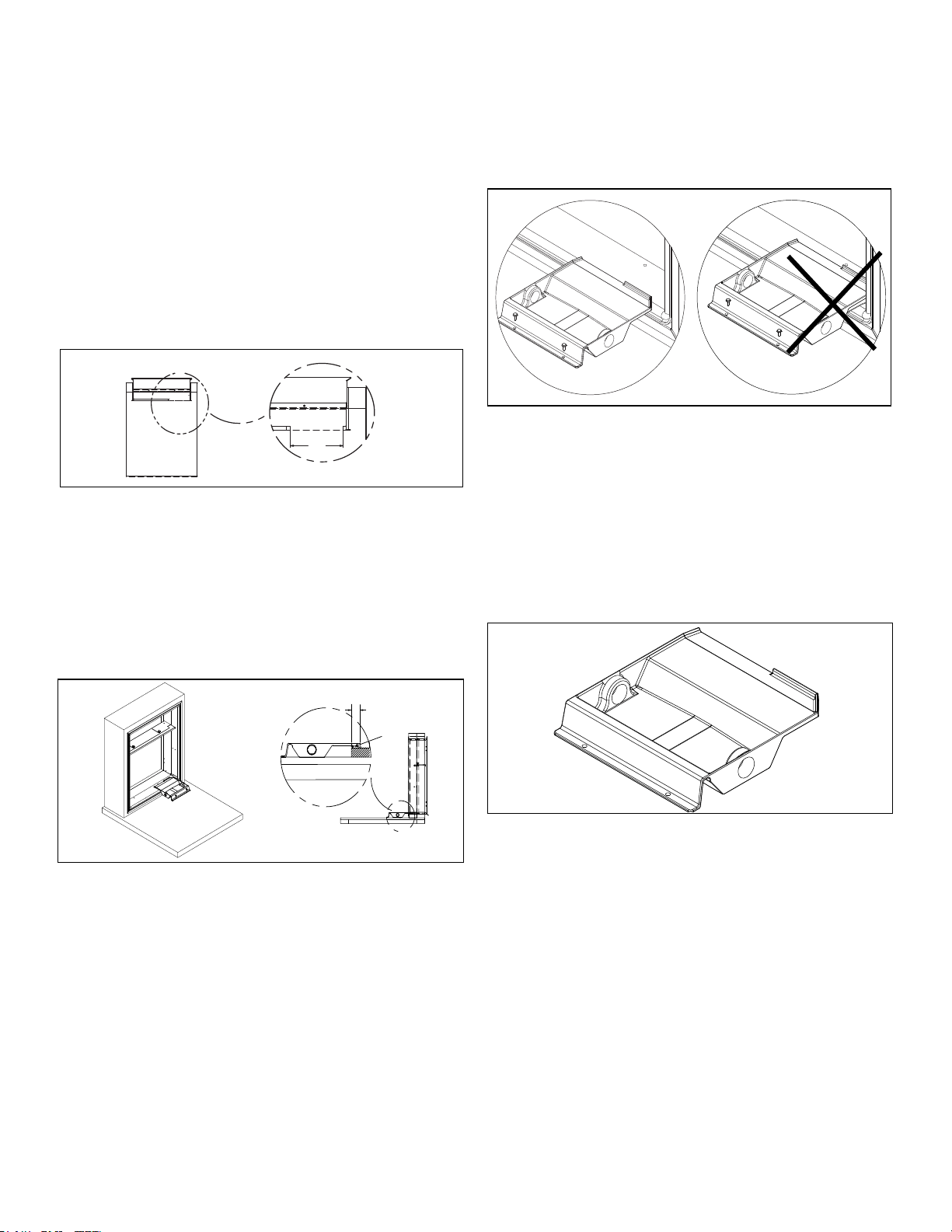
DRAIN PAN INSTALLATION
NOTE: This drain pan must be installed with all and
AVH18-AVH24 "H" series units (Produced after
September 2019).
Cut Opening in Gasket
Remove an 8 1/8” portion of the weather seal
gasket from the bottom right surface of the plenum.
• Cut the gasket in the lower right corner of the plenum.
• Make a second cut 8 1/8” from the right corner. The.
gasket should peel away from the plenum leaving a
clean mounting surface (See Figure 1).
A
DETAIL A
8.125
Figure 1
Seal and Set Pan
Prior to placing the drain pan into the opening run a 1/4”
bead of sealant the entire width of the removed gasket.
The pan should be placed against the right edge of the
plenum (See Detail A) and the secondary overflow lip
inserted into the plenum NO DEEPER THAN 1.5 INCHES
to prevent water leaks (See Detail B).
Figure 2
Install Drain Pan
Attach the drain pan to the closet oor with the appropriate
eld supplied hardware.
Important: To prevent water leaks use only the factory
supplied mounting holes. NEVER make penetrations in the
drain pan itself.
Figure 3
Install Drain Plug
The drain pan comes with both left and right-hand drain
connections locations. Determine which of the two
connections will be used to drain the condensate. Then,
with the factory supplied drain plug, plug the unused
opening.
Important: Proper sealant must be applied to the
connection to prevent leaks.
Figure 4
11
B
1.50
B
Sealant
A
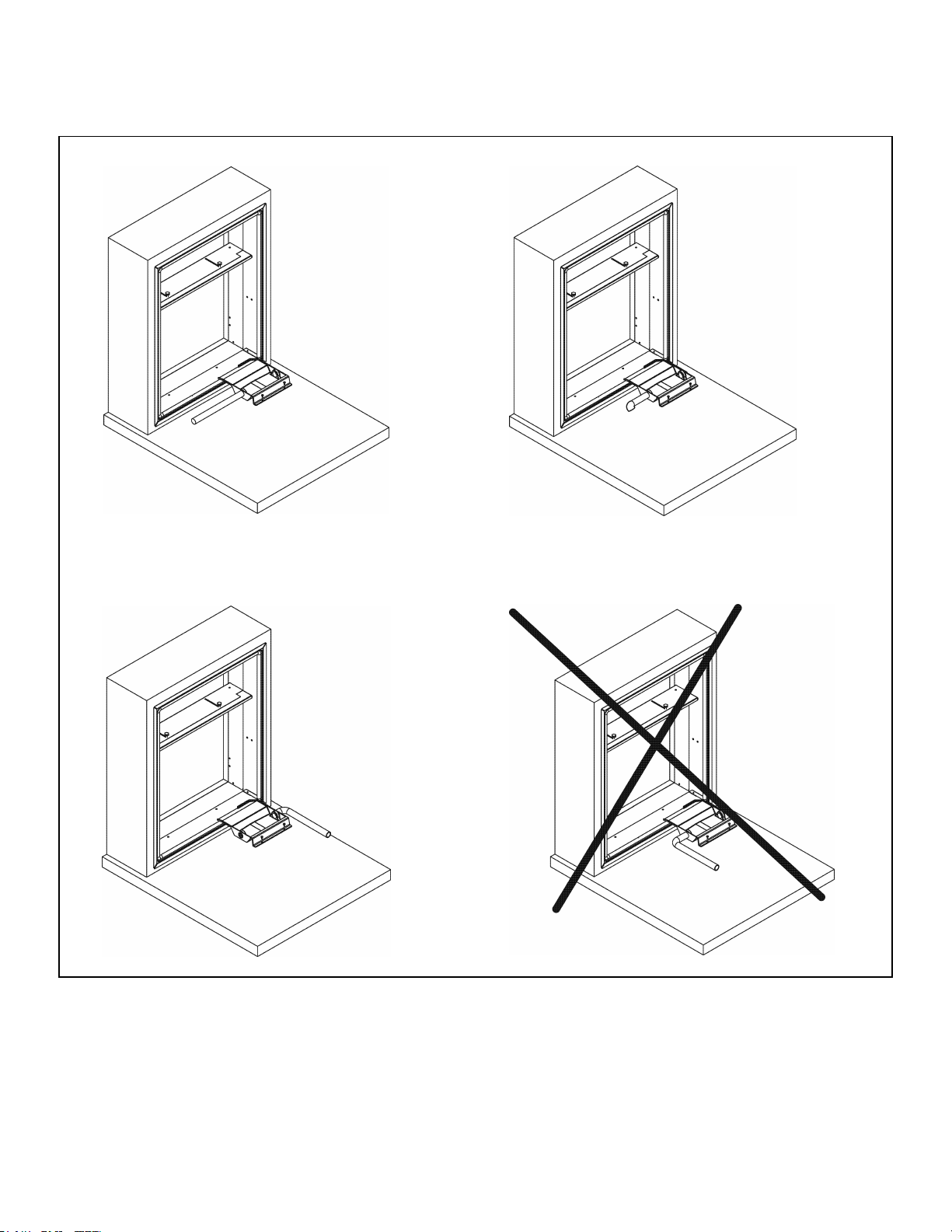
Install Drain Line
Condensate line routing options are shown below. Choose
the one that best suits your installation.
Important: Never run the condensate line as shown in
Option 4 below, as the drain line will come into contact with
the factory-installed isolators beneath the unit.
Figure 5
12
Option 1
Run condensate line
to left of unit
Option 2
Run condensate line
beneath unit platform
Option 3
Run condensate line
to right of unit
Option 4
Do not run
condensate line
back toward unit
WIRING
WARNING
HIGH VOLTAGE
DISCONNECT ALL POWER BEFORE SERVICING
OR INSTALLING THIS UNIT. MULTIPLE POWER
SOURCES MAY BE PRESENT. FAILURE TO DO SO
MAY CAUSE PROPERTY DAMAGE, PERSONAL
INJURY OR DEATH. DO NOT SERVICE THIS UNIT
WITHOUT FIRST SHUTTING OFF POWER TO THE
UNIT FROM THE CIRCUIT BREAKER AND/OR
REMOVING THE UNIT CORD SET PLUG FROM
THE WALL OUTLET.
WARNING
DO NOT ALTER POWER CORD.
DO NOT REMOVE LDCI OR AFCI CIRCUIT BOARD.
DO NOT REPLACE TERMINALS OR OTHER PARTS OF THE CORD.
DO NOT USE CORD IF DAMAGED.
CONTACT SERVICE PARTS FOR A REPLACEMENT CORD, IF
NEEDED.
WARNING
UNIT MAY ONLY BE HARD WIRED WITH A FACTORY SUPPLIED
KIT.
CAUTION
TO AVOID PROPERTY DAMAGE, PERSONAL INJURY OR DEATH
DUE TO ELECTRICAL SHOCK, DO NOT USE AN EXTENSION
CORD WITH THIS UNIT.
CAUTION
TO AVOID RISK OF PROPERTY DAMAGE, PERSONAL INJURY OR
FIRE, USE ONLY COPPER CONDUCTORS.
CAUTION
TO AVOID RISK OF PROPERTY DAMAGE, PERSONAL INJURY
OR FIRE, DO NOT INSTALL WITH POWER CORD STRETCHED OR
UNDER A STRAIN AS THIS MAY CREATE A LOOSE
PLUG/RECPTACLE CONNECTION.
CAUTION
TO AVOID THE RISK OF PERSONAL INJURY , WIRING TO THE
UNIT MUST BE PROPERLY POLARIZED AND GROUNDED.
WARNING
THIS AIR CONDITIONER IS NOT MEANT TO PROVIDE
UNATTENDED COOLING OR LIFE SUPPORT FOR PERSONS OR
ANIMALS WHO ARE UNABLE TO REACT TO THE FAILURE OF
THIS PRODUCT.
THE FAILURE OF AN UNATTENDED AIR CONDITIONER MAY
RESULT IN EXTREME HEAT IN THE CONDITIONED SPACE
CAUSING OVERHEATING OR DEATH OF PERSONS OR ANIMALS.
PRECAUTIONS MUST BE TAKEN TO WARN OFF OR GUARD
AGAINST SUCH AN OCCURRENCE.
13
Indoor Return Air Grille and Ductwork
Installation
AVLWP01A-R & AVLWP01A-L Return Air Grille with
Access Panel A field-supplied
(25” x 20”) filter can be
mounted inside the hinged access door. The door can
be installed with the grille oriented at the top of the panel
for improved sound attenuation (Recommended for
AVH09 & AVH12)
Option 1
Field Supplied Return Air Grille
A eld supplied return air grille divorced from the access
panel must have a minimum 250 square inches of free area.
Option 2
NOTE: All VTAC chassis are shipped with a filter
installed (20" x 14" for AVH09, AVH12, & AVH18. 20" x
18" for AVH24). If a different filter holder or location is
to be used, the filt
er on the chassis MUST be removed.
Ductwork
The supply duct system should be designed using a
recognized method such as the equal fraction or velocity
reduction method, using the appropriate duct calculator(s)
for the type(s) of duct being used in the system. The duct
system should be designed for a maximum friction rate
of .3” water column taking into consideration all fittings,
registers and/or diffusers.
NOTE: Do not operate the unit without a supply duct
attached. The return air to the VTAC unit MUST NOT
be ducted and all units must have a free return air
configuration to perform properly.
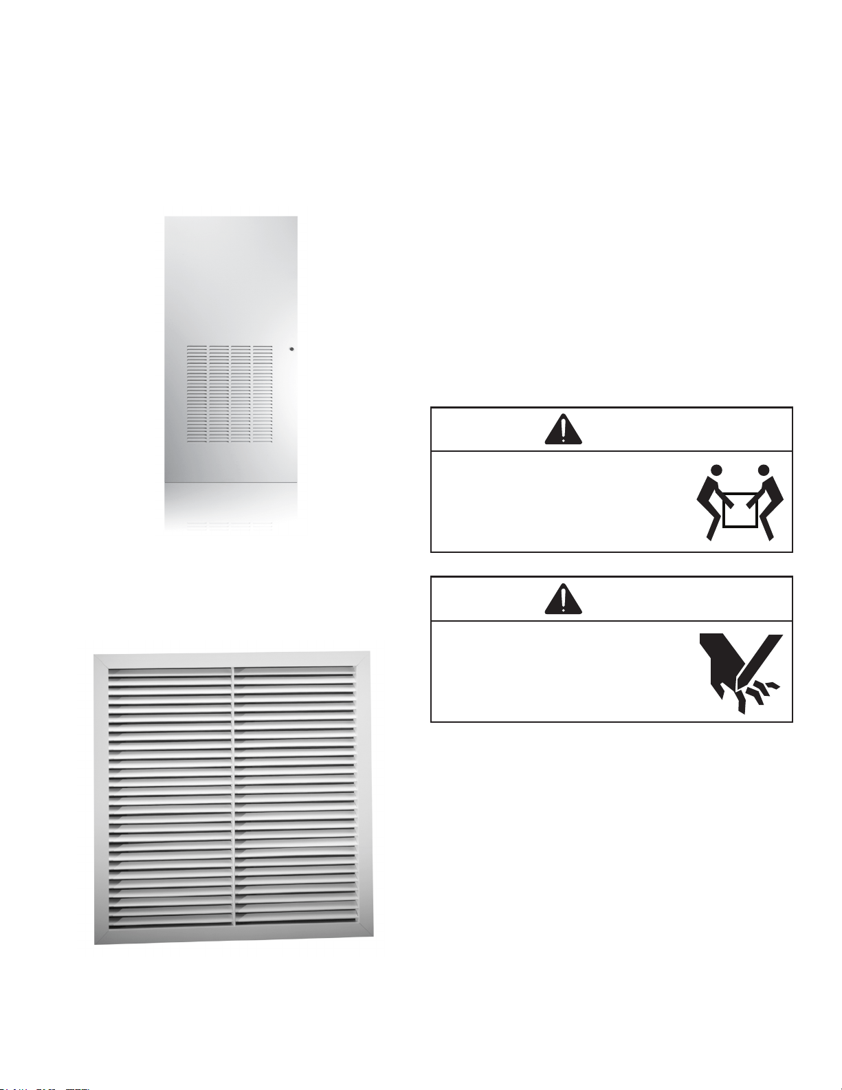
Chassis Installation
CAUTION
EXCESSIVE WEIGHT HAZARD
USE TWO OR MORE PEOPLE WHEN
INSTALLING YOUR AIR CONDITIONER.
FAILURE TO DO SO CAN RESULT IN BACK OR
OTHER INJURY.
CAUTION
CUT / SEVER HAZARD
SOME EDGES MAY BE SHARP, USE GLOVES
OR OTHER HAND PROTECTION WHEN
HANDLING UNIT.
FAILURE TO DO SO CAN RESULT IN MINOR TO
MODERATE PERSONAL INJURY.
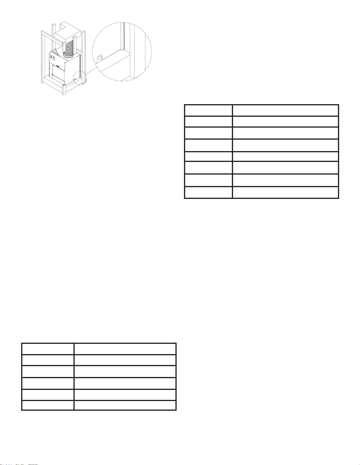
1. Ensure that the wall adapter and louver are installed
in accordance with the instructions listed on pages
5-7.
2. Place the chassis into the closet with the outdoor
side facing the wall adapter opening.
3. Slide the chassis into the wall adapter until the
adapter divider seal is established.
NOTE: The VTAC chassis must be inserted into the
wall adapter so that the adapter divider gasket makes
contact with the plastic condenser bafe on the unit.
The chassis will t approximately 2 3/8” into the wall
adapter.
14
Remote Thermostat and Low Voltage Control
Connection
Remote Thermostat
All VTAC units are factory congured to be controlled
by using a single stage heat/cool remote wall mounted
thermostat. The thermostat may be auto or manual
changeover as long as the control conguration matches
that of the VTAC unit.
To connect the wall mounted thermostat:
1. Pull the disconnect switch.
2. Unscrew and remove the control box panel.
3. Select which side to run your thermostat wire.
4. Run the wires through the side hole in the box to
reach the connection terminal wiring.
5. Make the connections, appropriately matching the
wires as shown in the wiring diagram.
6. Reattach the control box cover.
Front Desk Control Terminals
The VTAC has built-in provisions for connection to an
external switch to control power to the unit. The switch can
be a central desk control system door switch.
For desk control operation, connect on side of the switch to
the D1 terminal and the other to the D2 terminal. When the
circuit is closed, unit operation will stop.
NOTE: The desk control system and switches must be
eld supplied.
Maximum Wire Length for Desk Control Switch
AWG Wire Size Maximum Length (ft.)
24 400
22 600
20 900
18 1500
16 2000
Auxiliary Fan Control
The VTAC also has the ability to control a 24VAC relay to
activate an auxiliary or transfer fan. The outputs are F1 and
F2 on the control board.
To connect the relay, simply wire one side of the relay to F1
and the other side to F2.
NOTE: The relay and auxiliary fans must be eld
supplied. The relay must be 24VAC @ 100mA or less.
Interface Denition
Terminal Code Wire Connection Function
C Common Ground Terminal
GH Call for High Fan
GL Call for Low Fan
B Call for Heat Pump (Reversing Valve)
Y Call for Compressor
W Call for Heating (Electric)
R 24VAC to Wall Thermostat
NOTE: It is the installer’s responsibility to ensure that
all control wiring connections are made in accordance
with the installation instructions. Improper connection
of the thermostat control wiring and/or tampering
with the unit’s internal wiring can void the equipment
warranty and may result in property damage, personal
injury, or death. Questions concerning proper
connections to the unit should be directed to the
factory.
15
Final Installation Checklist
WARNING
HIGH VOLTAGE
DISCONNECT ALL POWER BEFORE SERVICING
OR INSTALLING THIS UNIT. MULTIPLE POWER
SOURCES MAY BE PRESENT. FAILURE TO DO SO
MAY CAUSE PROPERTY DAMAGE, PERSONAL
INJURY OR DEATH.
• Inspect and ensure that all components and
accessories have been installed properly and that
they have not been damaged during the installation
process.
• Ensure that all installation instructions concerning
clearances around the unit have been adhered
to.
• Check to ensure that the unit air lter, indoor coil, and
outdoor coil are free from any obstructions.
• Ensure that the circuit breaker(s) or fuse(s)
and supply circuit wire size have been sized
correctly.
• Check the condensate water drain(s) to ensure that
they are adequate for the removal of condensate
water and that they meet approval of the end
user.
• Ensure that the entire installation is in compliance
with all applicable national and local codes and
ordinances having jurisdiction.
• ENSURE THAT THE SUPPLY VOLTAGE TO THE
UNIT IS WITHIN THE OPERATING RANGE
• Secure all access panels (i.e. front cover and/
or control box), apply power to the unit. The unit
commissioning should be done at this time to ensure
unit function.
NOTE: Maintaining a log for recording the dates of
maintenance and/or service is recommended, and
should be suggested to the owner or operator of the
equipment.
• Present the owner or operator of the equipment with
the Installation & Operation Manual, all accessory
installation instructions, and the name, address and
telephone number Warranty Service Company in the
area for future reference if necessary.
NOTE: The unit is not designed to guarantee
continuous operation with outdoor ambient conditions
greater than 110°F.
Chassis Operation
Fresh Air Door
The fresh air door is an “intake” system. It is opened via
a slide mechanism on the front of the chassis located just
above the indoor coil. Move the slide left to open and right
to close the door. The system is capable of delivering up to
60 CFM of outdoor air.
Low Ambient Compressor Cut Out
Each chassis is equipped with low ambient protection
that is determined by thermistor feedback. The feedback
will prevent the compressor from operating at low suction
temperatures.
Room Freeze Protection
This feature will monitor the indoor room conditions and in
the event that the room falls below 40°F, the unit will cycle
on high fan with the electric heater. This occurs regardless
of mode.
Chassis Final Connections
With the chassis in place, you are now ready to begin
chassis connections:
A. Move the thermostat switches to “OFF” and “AUTO”.
This will keep the thermostat from cycling the chassis
until nal connections are complete.
B. Connect the duct work onto the 10” collar. Plastic
wire ties (eld supplied) are suggested to secure
the duct work in place. Use 2 wire ties, one for each
inner and outer ex duct sleeve.
C. Review the Final Installation Checklist before
replacing the power quick disconnect, reconnecting
power to the chassis, or operating the chassis.
WARNING
HIGH VOLTAGE
DISCONNECT ALL POWER BEFORE SERVICING
OR INSTALLING THIS UNIT. MULTIPLE POWER
SOURCES MAY BE PRESENT. FAILURE TO DO SO
MAY CAUSE PROPERTY DAMAGE, PERSONAL
INJURY OR DEATH.
Service & Warranty
Servicing / Chassis Quick Changeouts
The chasis is designed for quick disconnect and change
out. For minor electrical service, the control box cover
lifts straight up after the screws & disconnect head are
removed. For major electrical, refrigeration and fan service
the chassis may be removed from utility closet.
16
WARNING
HIGH VOLTAGE
DISCONNECT ALL POWER BEFORE SERVICING
OR INSTALLING THIS UNIT. MULTIPLE POWER
SOURCES MAY BE PRESENT. FAILURE TO DO SO
MAY CAUSE PROPERTY DAMAGE, PERSONAL
INJURY OR DEATH.
Routine Maintenance
Performing Routine Maintenance
With the proper maintenance and care, your system will
operate ecomomically and dependably. Maintenance
can be accomplished easily by referring to the following
directions. However, before performing any maintenance,
see above stated WARNING.
CAUTION
CUT / SEVER HAZARD
SOME EDGES MAY BE SHARP, USE GLOVES
OR OTHER HAND PROTECTION WHEN
HANDLING UNIT.
FAILURE TO DO SO CAN RESULT IN MINOR TO
MODERATE PERSONAL INJURY.
Replace Air Filter
A dirty air lter reduces the efciency of the VTAC and
allows lint and dirt to accumulate on the indoor-air coil. Lint
and dirt on the indoor-air coil can damage your unit.
The air lter should be replaced as it becomes dirty.
To replace the lter (chassis mounted return air lter):
1. Slide the lter clear of the lter rails.
2. Remove the lter.
3. Install new disposable lter.
NOTE: DO NOT OPERATE YOUR SYSTEM WITHOUT
A FILTER IN PLACE OR BLOCK THE FRONT OF THE
UNIT RETURN AIR OPENING.
To Remove the Chassis from the Closet:
A. Switch the wall thermostat off.
B. Pull the Power Disconnect located in the front of the
chassis.
C. Disconnect the power coming into the unit from
the main breaker panel or the closet mounted
disconnect.
D. Disconnect the electrical connection.
E. Disconnect the duct work.
F. Slide the chassis out of the wall adapter.
G. Lift the chassis out of the utility closet.
Inspect and Clean Indoor-air Coil
Eventually, minor amounts of lint and dirt may pass
through the lter and collect on the indoor-air. These minor
accumulations can be carefully vacuumed away with a
brush attachment on a vacuum claner. Care must be taken
to avoid bending the aluminum nns on the coil. Bent ns
should be straightened using a special n tool avalable
from most HVAC supply depots.
Inspect Outdoor-Air (OA) Intake and Exhaust
The unit’s outdoor-air intake and outdoor-air exhaust paths
must remain clear. Check the OA exhaust frequently. Keep
it free of all debris, snow, or ice. The OA intake should also
be kept free of obstructions. Blocking the OA exhaust or
OA intake opening will reduce the efciency of your unit
and could damage it.
Inspect and Clean Condensate Drain
The condensate drain must be routed to a suitable
drainage area. Check the unit condensate drain
periodically. Keep it free of anything that may block or
impede the ow of condensate water. If there is any
accumulation of foreign matter in the drain pipe, it should
be removed and cleaned. The entire drain line must be
protected from freezing.
Warranty
All warranty service work must be done by an authorized
servicer. See Product Warranty, and consult your dealer or
contractor for details.
Electronic Control Error Code Diagnostics
and Test Mode
Error Code Diagnostics
The VTAC electronic control continuously monitors the
VTAC unit operation and will store error codes if certain
conditions are witnessed. In some cases the unit may take
action an shut the unit off until conditions are corrected.
To access the error code menu press the ‘ENTER’ button.
If error codes are present they will be displayed. If multiple
codes exist you can toggle between error codes using the
‘SCROLL’ button. To clear all codes press the ‘ENTER’
and ‘SCROLL’ buttons for three seconds while in the error
code mode. To exit without losing codes press the “LOW
FAN” button.
17
ERROR CODES AND ALARM STATUS
Unit Control Panel
The display shown below has four (4) digits. The left two digits indicate the error code (1 to 24), The On/Off icons above
these two digits indicate the currents state of the error code. The right two digits show the history count (up to 99) of the
associated error code. The display contains a maintenance icon (wrench) that will illuminate to indicate when the unit
needs maintenance.
Error
Code
Problem Action
1
Front Panel Button Stuck For More Than 20 Seconds Continue to Monitor for “OPEN” (Unstuck) switch. Do not process switch input.
2
Input Voltage Out of Specication (103-127/187-253) Unit stops, open all relays until voltage is back within specs then resume
operation.
3
Indoor Temperature Sensor is Open or Shorted Unit defaults to 75°F in COOLING or 68°F in HEATING and will continue to
operate.
4
Indoor Coil Temperature Sensor is Open or Shorted The unit’s control board defaults 40°F. It will override the sensor and the unit will
continue to operate.
5
Outdoor Coil Temperature Sensor is Open or Shorted The unit defualts to 20°F, overriding the sensor. The unit will continue to operate.
Using Elec Heat if available for HEATING. If not available, it will use HEAT PUMP
if the outdoor temperature allows.
6
Outdoor Coil > (greater than) 175°F The unit will shut down for 5 minutes. Resume operation for 3 minutes. If test fails
3 times, the severity is increased and the unit operation is locked out.
7
Indoor Coil < (less than) 30°F for 2 consecutive
minutes
The compressor will turn off and the High Fan speed will run. When coil temp
reaches 45°F the unit will resume operation after lockout time.
8
Unit Cycles > (greater than) 9 Times per hour The unit will continue to operate and be monitored.
9
Unit Cycles < (less than) 3 Times per Hour The unit will continue to operate and be monitored.
10
Room Freeze Protection Only use if Electric Heat is available. Run High Speed and Electric Heat until room
temp reaches 46°F. The unit will display “FRZ” during operation. Logged Only.
11
WallStat Problem or Connection Issue The unit will not operate.
12
Not Applicable Not Applicable
13
High Pressure LImit Switch is Open If unit is cooling or heat pump is on, shut down compressor. Run high fan until
switch closes, then resume operation. The third occurance in 1 hour locks unit out.
Applicable to 24K unit only.
14
Not Applicable Not Applicable
15
Heat Pump Error If indoor coil temperature is less than ambient temperature for 3 minutes the unit
will use electric heat to satisfy the heating demand.
16
Temperature Beyond Operating Limits Occurs if the ambient temperature range falls below 0°F or greater than 130°F.
The error code will remain on until the temperature reaches the operating range
and then the unit will return to normal operation.
17
Equipment Doesn’t Meet Minimum Conguration The compressor must be enabled and have at least 2 fan speeds
18
Not Applicable Not Applicable
19
Not Applicable Not Applicable
20
Not Applicable Not Applicable
21
Not Applicable Not Applicable
22
Outdoor Coil Temperature < 30°F for 2 consecutive
Minutes
Unit will use electric heat to satisfy heating demands until the tempearture equals
or exceeds 45°F. Applicable for Heat Pump models only.
23
Frost Protection Unit will run active defrost for a minimum of 6 minutes when Heat Pump run time is
greater than 60 minutes and outdoor coil temperature is 26°F or less.
24
Not Applicable Not Applicable
18
Obtaining Service
In the event this unit requires repair or servicing beyond what is covered in this manual, contact an authorized service
organization.
To obtain an authorized servicer, contact your sales representative.
5151 San Felipe, Suite 500 • Houston, TX 77056 • www.amana-ptac.com
© 2014 - 2015, 2017 - 2020 Goodman Company, L.P.
is a registered trademark of Maytag Corporation or its related companies and is used under license
to Goodman Company, L.P., Houston, TX, USA. All rights reserved.
CUSTOMER FEEDBACK
Daikin is very interested in all product comments.
Please ll out the feedback form on the following link:
https://daikincomfort.com/contact-us
You can also scan the QR code on the right to be directed to the feedback page.
19