Marvel and
Marvel Professional
Under Counter Product
Service Manual
Beverage Centers - Wine Cellars - All Refrigerators -
Refrigerated Drawers - Refrigerator Freezers - Beer
Dispensers - Outdoor Models - Clear Ice Machines
Second Edition
41013818-Rev B; August 2015


i
Section 1: Introduction
1.1 Unit Specifications
1.2 Serial Nameplate
1.2.1 Serial Description
1.3 Servicing
1.4 Basic Refrigeration Tools
1.5 Basic Installation
1.6 Electrical Requirements
Section 2: Sealed System
2.1 Introduction
2.2 Low Side Leaks
2.3 High Side Leaks
2.4 Restricted Capillary Tube
2.5 Access Valves
2.6 Evaporator Frost Pattern
2.7 Measuring Evaporator Temperatures
2.8 Re-charging
2.9 Pressure and Temperature Chart
Section 3: Sealed System Components
3.1 Toe Grille Removal
3.2 Warning and Cautions
3.3 Accessing the Machine Compartment
3.4 Compressor
3.4.1 Check Compressor Winding Resistance
3.4.2 Compressor Removal
3.4.3 Compressor Installation
3.5 Condenser
3.5.1 Condenser Removal
3.5.2 Condenser Installation
3.6 Evaporator
3.6.1 Evaporator Removal
3.6.2 Evaporator Installation
Section 4: Electrical Component Access
4.1 Condenser Fan
4.1.1 Fan Assembly Removal
4.1.2 Fan Assembly Replacement
4.1.3 Fan Motor Installation
4.1.4 Condenser Fan Blade Spacing
4.2 Evaporator Fan Access
4.3 Thermistor Locations
Section 5: User Interface Display
5.1 Model Variations
5.2 User Interface Navigation: Beverage Center
5.3 User Interface Navigation: Wine Coolers
5.4 User Interface Navigation: Refrigerated Drawers
5.5 User Interface Navigation: Beer Dispensers
Section 6: Control System
6.1 User Interface Assembly
6.1.1 Removing the User Interface
6.1.2 Installing a Replacement Interface
6.2 Main Control Board Assembly
6.2.1 Main Control Replacement
6.2.2 Removing the Programming Data Cable
6.2.3 Replacing the Programming Data Cable
6.2.4 Main Control Board Installation
6.3 Cabinet and Defrost Thermistors
6.3.1 Thermistor (Sensor)
6.3.2 Check the Thermistor
6.3.3 Removing the Cabinet Thermistor
6.3.4 Installing the Cabinet Thermistor
6.3.5 Removing the Defrost Thermistor
6.3.6 Installing the Defrost Thermistor
6.3.7 Thermistor Harness Identification
6.4 Temperature Resistance Chart
6.5 Door Sensor
6.5.1 Door Sensor Removal
6.5.2 Door Sensor Replacement
6.6 Defrost Modes
6.6.1 Defrost Characteristics
6.6.2 Auto Defrost
6.6.3 Manual Defrost
6.7 Error Codes
Section 7: Lights, Doors, Drawer, & Hinges
7.1 LED Lights
7.1.1 LED Light Replacement
7.2 Cabinet Door
7.2.1 Door Removal
7.2.1.1 Marvel & non Overlay Models (standard
hinge)
7.2.1.2 Marvel Pro and Overlay Models (articulating
hinge)
7.2.2 Bottom Door Closer
7.3 Refrigerated Drawers
7.3.1 Drawer Removal
7.4 Door and Drawer Handle Adjust
7.5 Door Alignment and Adjust
7.6 Door and Drawer Gasket Adjust and Replace
7.7 Articulating Hinges
Section 8: Evaporator Compartment Access
8.1 Beverage Centers
8.2 Wine Coolers
8.3 Refrigerated Drawers
8.4 Evaporator Cover Drip Edge

ii
Section 9: Wiring Diagrams
9.1 Block Diagram
9.2 Wiring Schematics - All
9.3 Main Power Board Identification
9.3.1 Single Zone
9.3.2 Dual Zone
Section 10: Power on Reset Mode
10.1 Auto Self-Test
10.2 Manual Auto Test
10.3 Control Types
10.3.1 Single Zone
10.3.2 Dual Zone
Section 11: Quick Reference Troubleshooting
Section 12: Diagnostic Flow Charts
12.1 Does Not Run
12.2 Too Cold
12.3 Not Cooling
12.4 Runs Continuously
12.5 Excessive Noise
12.6 LED Lighting
Section 13: Gathering Service Data
13.1 Program Port
13.1.1 Service Data Retrieval
13.1.2 Service Data Port Location
13.1.3 Onboard Diagnostics
Section 14: Beer Dispenser
14.1 Internal / External Components
14.2 Main Control Board Access
14.3 Machine Compartment
14.3.1 Refrigeration and Mechanical
14.4 Excerpts from Owners Maintenance Guide
Section 15: Dual Zones
15.1 User Interface Control
15.2 Operation
15.3 Characteristics
15.4 Compartment Air Flow
15.5 Damper Removal
15.6 Damper Operation
15.7 Compartment Fan Operation
15.8 Heater Operation
15.9 Thermistors
15.10 Evaporator Access
15.11 Interior LEDs
15.12 Defrost – Drip Time
15.12.1 Defrost Sequence
15.13 Refrigeration & Mechanical
Section 16: Refrigerator Freezers
16.1 User Interface Control
16.2 Operation
16.3 Characteristics
16.4 Damper Operation
16.4.1 Damper Access
16.5 Fan Operation
16.5.1 Refrigerator Supply Air
16.5.2 Freezer Supply Air
16.6 Thermistors
16.6.1 Thermistor Type
16.6.2 Thermistor Location
16.7 Refrigeration and Mechanical
16.8 Evaporator
16.8.1 Evaporator Type
16.8.2 Evaporator Location
16.9 Defrost
16.9.1 Defrost Function
16.9.2 Defrost Heater
16.9.3 Defrost Thermistor
16.9.4 Defrost Termination Thermostat
16.9.5 Defrost Drip Time
16.10 Access to Defrost Components
16.10.1 Defrost Heater
16.10.2 Defrost Termination Thermostat
16.10.3 Defrost Thermistor
16.11 RFI (Refrigerator Freezer with Ice Maker)
16.11.1 Ice Maker
16.11.1.1 Ice Maker Specs
16.11.1.2 Ice Maker Test Cycling
16.11.1.3 Water Flow Volume
16.11.2 Ice Maker Removal
16.11.3 Ice Maker Kit
16.11.3.1 Ice Maker Kit Installation Instructions
16.11.3.2 Installation Schematic
Section 17: Outdoor Models
17.1 Operation
17.2 Characteristics
17.3 Fan Operation
17.4 Thermistors
17.5 Control Type
17.6 Control Features
17.7 Control Locations by Model
17.7.1 Beverage Centers and Dispensers: 6 cu. ft.
17.7.2 Beverage Center: 3 cu. ft.
17.7.3 Refrigerated Drawers
17.8 Machine Compartment
17.9 Main Power Board Access
17.10 Display Access and Replacement
17.10.1 Beverage Center: 3 cu. ft.
17.10.2 Beverage Centers and Dispensers: 6 cu. ft.

iii
17.10.3 Refrigerated Drawers: 6 cu. ft.
17.11 Thermistor Resistance Chart
17.12 Wiring Diagram
17.13 Generic Troubleshooting Table
17.13.1 Refrigerated Drawers
17.13.2 Beverage Centers and Dispensers
17.14 Refrigeration and Mechanical
Section 18: Prime Control
18.1 Control Type
18.2 Control Functions
18.3 Fan Operation
18.4 Thermistors
18.5 Machine Compartment
18.6 Thermistor Resistance
18.7 Wiring Diagram
18.8 Generic Troubleshooting Table
18.9 Refrigeration and Mechanical
Section 19: Clear Ice Machines
19.1 Control Operations
19.2 Control System
19.3 Interior Features
19.4 Machine Compartment
19.5 Diagnostic Test Mode
19.6 Diagnostic Charts
19.7 Troubleshooting
19.8 VAC Wiring Diagram
19.9 Specifications
19.10 Ice Production & Harvest Guidelines
Section 20: Service Kits/Bulletins
20.1 Refrigerated Drawer – Mullion Heater Kit
20.2 Evaporator Replacement Kit (also refer to
section 3.6)
20.3 Door Sensor and Spacer Installation
20.4. Slotted Condenser Shroud
20.5 Showroom Mode Alarm
20.6 Evaporator and Heat Exchanger Replacement
(RF and RFI Models Only)
20.7 Shelf Shim Kit (Non-Professional Models)
20.8 Miscellaneous Control Communication Errors
20.9 Door Skin Replacement on MP Models
Section 21: Customer Service Contact Information
Section 22: Notes
Blank Pages Added
At the time of the release of this manual; all information, parts, and procedures were current.
AGA Marvel reserves the right to make continual changes with the product to strive for
continuous improvement.
For product updates, revised literature, or related service bulletins please visit our customer
service website
www.marvelservice.com
A username and password will be needed to access this website, if you currently do not have
access, please contact 1-800-223-3900.
If you would like to speak with a Customer Service representative for technical or part order
assistance, call 1-800-223-3900. Please follow the phone queue to the correct department to
avoid unnecessary delays.
1
Section 1: Introduction
1.1 Unit Specifications:
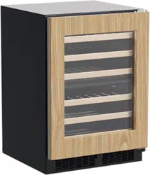
(Single Zone) WINE COOLERS, BEVERAGE CENTERS, ALL REFRIGERATORS
Performance Data: No Load & No Door Openings @ Control Setting of Mid
Type A with Run Capacitor
65°F (18°C) Ambient
90°F (32°C) Ambient
Operating Time
8 - 15% (wine cooler)
15 - 35% (beverage center / refrigerator)
20 - 40% (wine cooler)
35 - 55% (beverage center/refrigerator)
Wine Cooler Temperature
40°F - 65°F
40°F - 65°F
Beverage Center / All Refrigerator Temperature
34°F - 42°F
34°F - 42°F
Low Side Pressure (cut in)
25 - 50 psig (172 - 345 kPa)
25 - 50 psig (172 - 345 kPa)
Low Side Pressure (cut out)
0 - 10 psig (0 - 69 kPa)
0 - 10 psig (0 - 69 kPa)
HIgh Side Pressure (last 1/3 of cycle)
95 - 125 psig (655 - 862 kPa)
130 - 175 psig (896 - 1207 kPa)
Wattage (last 1/3 of cycle)
55 - 80
55 - 80
Amps (running)
.45 - .85
.45 - .85
Base Voltage
115 VAC (127 VAC max)
115 VAC (127 VAC max)
R-134A Charge in Ounces: 3.0
Compressor
120 volt/60 hertz
BTU/HR: 200
LRA: 5.22
Condenser Fan Motor
Watts
RPM
Amps
4.1
1280
0.06
Evaporator Fan Motor
Watts
RPM
Amps
1.08
2550
0.09
REFRIGERATED DRAWERS
Performance Data: No Load & No Door Openings @ Control Setting of Mid
Type A with Run Capacitor
65°F (18°C) Ambient
90°F (32°C) Ambient
Operating Time
8 - 15%
20 - 40%
Temperature
34°F - 42°F
34°F - 42°F
Low Side Pressure (cut in)
25 - 50 psig (172 - 345 kPa)
25 - 50 psig (172 - 345 kPa)
Low Side Pressure (cut out)
0 - 10 psig (0 - 69 kPa)
0 - 10 psig (0 - 69 kPa)
HIgh Side Pressure (last 1/3 of cycle)
95 - 125 psig (655 - 862 kPa)
130 - 175 psig (896 - 1207 kPa)
Wattage (last 1/3 of cycle)
55 - 80
55 - 80
Amps (running)
.45 - .85
.45 - .85
Base Voltage
115 VAC (127 VAC max)
115 VAC (127 VAC max)
R-134A Charge in Ounces: 3.0
Compressor
120 volt/60 hertz
BTU/HR: 200
LRA: 5.22
Condenser Fan Motor
Watts
RPM
Amps
4.1
1280
0.06
Evaporator Fan Motor
Watts
RPM
Amps
1.08
2550
0.09
2
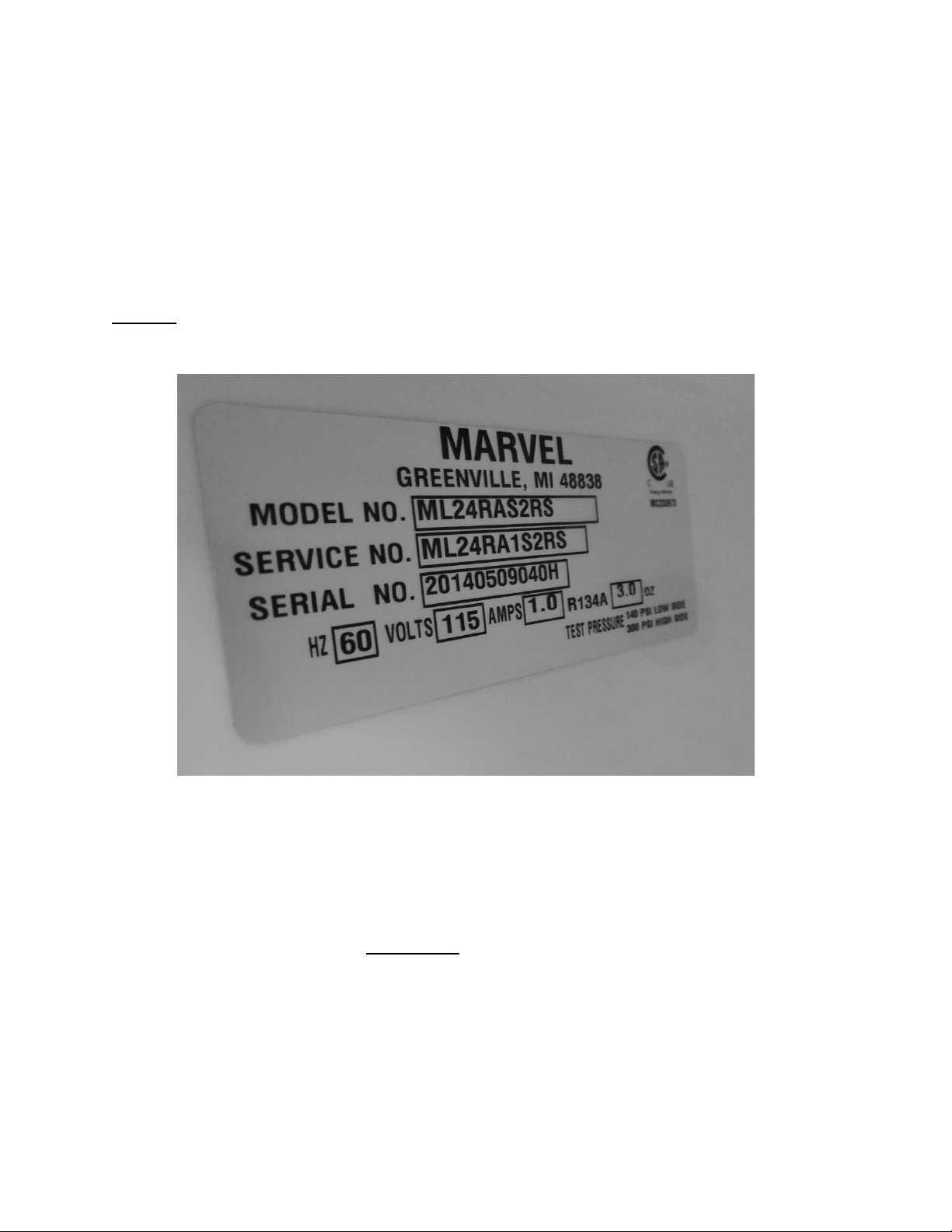
1.2 Serial Nameplate:
The serial plate location is model dependent on the beverage centers, wine coolers and
refrigerated drawer models. The serial plate is located on the inside of the cabinet affixed to
the left hand side (top or bottom) of the plastic liner.
Beverage centers and wine coolers: Upper front corner on left hand side of liner.
Refrigerated drawers: Left hand liner bottom, front side beneath the bottom drawer.
NOTE: The model, service, and serial number will need to be given when
inquiring about the unit or ordering parts.
1.2.1 Serial Number Description:
EXAMPLE: 20140509040H
Breakdown of the 12 Digit Serial Number:
Read the number sequence from left to right:
Digit number 1 thru 4 (2014) Year of manufacture (2014)
Digit number 5 and 6 (05) Month of manufacture (May)
Digit number 7 and 8 (09) Day of manufacture (09; 9)
Digit number 9 thru 11 (040) Sequence of manufacture
Digit number 12 (H) Manufacturing facility (Greenville)

3
1.3 Servicing
• Always disconnect power to any appliance before attempting to service it. Always verify
that the power has been disconnected.
• If the unit has been running, use caution around the compressor, condenser and copper
tubing. These areas may be very hot.
• Use caution around the condenser wires and metal edges. These areas could be sharp.
• Refrigerant is under high pressure. Always evacuate any system before attempting to
open it.
• Reasonable care and safe work methods should be practiced when working on any
appliance.
• Never work with energized electrical equipment in wet or damp areas.
• Use an appropriate work area and location when performing repairs. Under counter
appliances are much easier to repair if they are set on a raised platform or workbench.
• Protective safety glasses are recommended.
• Any refrigerant, whether CFC, HCFC, or HFC (R-12, R-22, or R-134a), must be recovered.
Federal regulations prohibit the intentional venting or release of refrigerants during the
service repair or disposal of an appliance.
1.4 Basic Refrigeration Tools
The following list contains some of the tools required for basic refrigeration repairs:
1. Hoses with R-134a couplers (must meet standards for handling R-134a refrigerant)
2. Approved and certified recovery system for R-134a
3. Manifold gauge set or a short length of charging hose for R-134a
4. 25 pound charging cylinder with R-134a
5. Electronic refrigerant scale
6. Access valves or process kit
7. Pinch off tool
8. Small, fine grade, 3-corner file or appropriate cap tube cutting tool
9. Small and large tubing cutter
10. Oxy-Acetylene or Map-Pro torch
11. Swaging tools
12. Digital multi meter
13. Leak detection equipment
14. Standard hand tools (assorted Phillips and standard screwdrivers, sockets, Allen
wrenches, combination wrenches / adjustable wrenches, needle nose / slip joint pliers
etc.)
15. Rivet gun and assorted rivets
16. Drill motor with assorted drill bits and hex head sockets
17. Wire strippers and crimpers

4
1.5 Basic Installation
Units can be installed freestanding* or built-in. The front of the unit must be
unobstructed for proper air circulation and operation at all times.
NOTE: * Professional and overlay door models cannot be installed free standing. Units
with the “Articulating Hinge” must be installed as built-in due to safety restraints.
Area should be ventilated and without exposure to extreme temperatures.
Unit must be installed indoors and away from the elements of nature. These units do
not have certification from any agency for outdoor installation.
Any exceptions, alterations, or modifications to the appliance as manufactured will void
the warranty.
These units must be installed on a flat, level surface capable of supporting the loaded
weight of the appliance.
WARNING HAZARD OF ELECTRICAL SHOCK
Failure to disconnect the supply voltage to the appliance prior to servicing
could result in an electrical shock or possible death.
1.6 Electrical Requirements
115 / 120 VAC, 60 hertz, single phase power is required.
Use an outlet with a 15 amp delayed action fuse or circuit breaker.
DO NOT PUT A FUSE
ON THE NEUTRAL OR GROUND SIDE OF THE CIRCUIT
.
A properly grounded outlet is required for this appliance.
It is recommended that a single circuit receptacle be used for this appliance. Multiple
appliances on the same electrical circuit are not recommended.
DO NOT use an extension cord or multi-purpose surge protector device.

5
Section 2: Sealed System
2.1 Introduction
The following should always be practiced with any sealed system that has been opened. Only
open the sealed system after proper diagnosis has verified a system issue. Eliminate any
possible non system related problems such as wiring, control system, airflow, etc. before
attempting a sealed system repair. Many times these possibilities can resemble sealed system
problems. Checking the evaporator frost pattern is a great way to determine if a possible
charge related problem is evident.
1. Use a leak detection system that will detect R-134a refrigerant. Check both the high and
low sides slowly for minuscule leaks.
2. The drier must be replaced anytime the sealed system is opened. Always use an
unopened and approved drier. Failure to do so may cause repeated system failure in the
future.
3. Limit time the system is opened. DO NOT EXPOSE THE OPEN SYSTEM FOR MORE THAN
15 MINUTES. This could result in a sealed system failure. Leave replacement parts
sealed and unexposed to the surrounding atmosphere until they are ready to install.
4. Replacing the compressor for a low side leak is not always mandatory. If the system has
not been purged dry of refrigerant and oil as a result of a low side leak, the sealed
system should not be compromised. However, if the system has been purged
completely of refrigerant, a compressor replacement should be completed. Moisture
has been drawn into the system if the unit has been running dry for an extended period
of time. Be sure to flush the system with dry nitrogen gas and evacuate to 50 microns
before re-charging.
5. A new evaporator assembly must be ordered if the capillary tube is found to be plugged
or severely restricted. Restrictions cannot be flushed out.
6. Be sure to purge the system after final brazing. This will flush out any air or moisture
that may have entered the system before being absorbed into the ester oil.
7. A sealed system that has been contaminated by moisture is a very costly repair for the
customer. If the appliance is still under warranty, it would be best to contact the
manufacture for recommendations for either a sealed system replacement or appliance
replacement.
2.2 Low Side Leaks
Low side leaks consist of a break in the system at the evaporator, suction line, or compressor. If
a leak is found in any of these areas, there is a possibility that moisture has been introduced
into the sealed system. The compressor and drier will have to be replaced and the system will
need to be flushed thoroughly with nitrogen gas and evacuated to 50 microns before re-
charging.

6
2.3 High Side Leaks
High side leaks consist of a break in the system at the compressor, condenser, discharge tubing,
drier, or capillary tube. If a leak is found at any of these areas, replace or repair the leak. Flush
the system with nitrogen gas, evacuated to 50 microns, and recharged.
2.4 Restricted Capillary Tube
Moisture or other contaminants that enter the system can cause non condensable deposits in
the system. These deposits will usually collect in the capillary tube and form a restriction that
cannot be removed by flushing. If moisture is found in the system, the entire system has been
compromised due to the unstable relationship between ester oil and moisture.
For non-moisture related restrictions: If the capillary tube is restricted, typically the restriction
is at the inlet end, inserted into the drier. This can be repaired by cutting off approximately 1”
of capillary tube, inserting the cut end into a new drier, and re-soldering the joint. If the leak is
elsewhere in the capillary tube, it would be best to replace the evaporator / heat exchanger
assembly, pull a satisfactory vacuum and recharge.
2.5 Access/Process Valves
A temporary access valve can be used to service or evaluate the system. From these temporary
access valves, you can recover, evacuate, and re-charge the system. The access valve will be
installed on the compressor’s process tube (low pressure side). Be sure to cap off the access
valve if you have not completed servicing. This will prevent contamination of the system and
temporarily prevent refrigerant from leaking. After servicing is complete, the temporary valve
must be removed from the sealed system. A pinch-off tool can be used to close off the process
tube downstream from the valve piercing. Once this is done, the temporary valve can be
removed and the pierced section of the process tube cut off. The open end of the process tube
can now be soldered/brazed shut to seal the system. Be sure to leak check after brazing.
If a permanent soldered/brazed Schrader valve is used, the cap must be snugged firmly after
service is completed.
2.6 Evaporator Frost Pattern
In the past Marvel has always recommended not using a gauge set to determine system
capacity and pressures. The amount of refrigerant in these systems is so minute, that any
amount of charge lost during gauge installation or removal can be detrimental to the
refrigeration system.
It was determined that checking the frost pattern on the evaporator was always a good
indicator for reference.
The following procedure was recommended to check a typical cold plate evaporator:
7
With the design of the new enhanced cabinet and low side design, checking the evaporator
plate in the above description has become somewhat complicated.
As an alternative to the above method, we offer two varying methods.
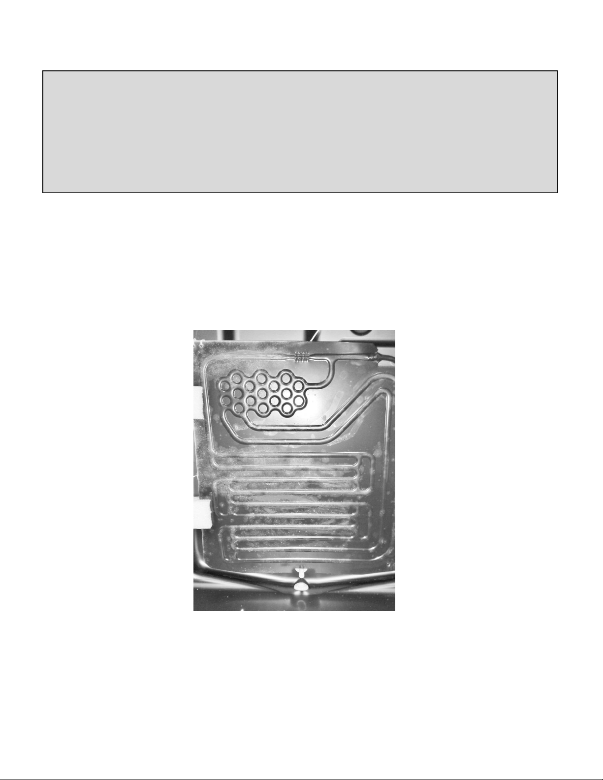
1) The first method is similar to the above. However, with the compressor running, the
interior evaporator cover must be removed, the evaporator fan disconnected, and
the door left open for observation for 10 minutes. The evaporator plate should show
a slight full frost pattern similar to the photo below with a typical factory refrigerant
charge as stamped on the manufacturer’s serial plate.
2) The second method which is somewhat unproven at this time is to measure the
temperature of the filter drier. A rule of thumb is that the drier temperature should
be approximately 90° F at a 70° F ambient temperature.
AGA Marvel does not recommend taking system pressures and does not have a
reference table to use for diagnosing or charging.
“Checking the evaporator frost pattern is a good way to quickly diagnose simple sealed system
problems. This can be done by allowing the unit to run (at least 10 minutes) with the door open for at
least 5 minutes. This will help speed up the normal frosting of the evaporator plate. By visually
inspecting the evaporator and feeling it with your hands, you will see and feel as the frost pattern builds
across the plate. The frost pattern should cover a majority of the evaporator plate. This will ensure the
system has been charged correctly and does not have a leak, partial restriction, or is undercharged. A
partial frost pattern may lead to excessive run times, reduced performance and efficiency.”
8
2.7 Measuring Evaporator Temperature
There are a couple of ways to measure temperature of the evaporator plate:
1. Use a thermocouple to measure the temperature of the evaporator plate. The
thermocouple must be secured to the evaporator when taking the measurement.
2. If it has been determined that there is proper contact between the sensor and
evaporator plate, the sensor resistance value can be interpolated to be the approximate
evaporator temperature.
2.8 Re-charging
CAUTION
Re-charging of the unit should be done only after diagnosing and repairing the system. Be sure
to flush the system with dry nitrogen gas and evacuate to 50 microns before re-charging.
Vacuum Chart
Vacuum: Inches Hg.
Microns
28.94
25000
29.53
10000
29.832
4600
29.882
1000
29.901
500
29.915
150
29.917
100
29.919
50
THIS IS A CRITICALLY CHARGED APPLIANCE
Charging by a weight system is recommended.

9
Charge the unit to the specified amount (See unit specifications or serial plate
for charge specifications per model).
---------------------------------------------------------------------------------------------------------------------------
Listed below are two variations to correctly charge the sealed system
Method 1- DIAL-A-CHARGE
Method 2- Weigh in Liquid on High Side
DIAL-A-CHARGE Method
Using a length of manifold hose, connect one end to the manifold, the other end to the
weighted charging cylinder.
Adjust cylinder to weigh in the correct amount of refrigerant into system based on nameplate
charge.
It is best to use low loss fittings on hoses to avoid loss of charge when removing hoses.
Purge air from cylinder hose to manifold by loosening cylinder hose at manifold and bleeding
liquid through hose to manifold.
Open manifold and charge unit.
Run unit for at least 10 minutes to confirm that the unit has a full frost pattern on the
evaporator and that the unit is not overcharged and there is no liquid returning back to the
compressor.
It is normal to have some condensation or slight frost on the suction line. Typically this will
occur towards the end of a run cycle. If the frost continues down the suction line to the
compressor, the system is overcharged.
Once the system is charged, clamp off the process tube downstream from the access valve.
Remove the valve, cut off the extra process tube with the piercing, fill the open end of the
process tube with solder. Remove the clamp from the process tube and leak check.
Vacuum Pump Tips:
1) Remember to change vacuum pump oil after evacuating a
contaminated system.
2) Frequent oil changes will increase the pumps potential to
achieve the best vacuum possible.
3) Use recommended oil per recommendation of vacuum pump
manufacturer.

10
Weigh in Liquid on High Side Method
NOTE: When using this method an access valve should have been attached to the compressor
process tube (low side) and the high side process tube on the drier.
Using a length of manifold hose, connect one end to the manifold, the other end to the
refrigerant cylinder.
It is best to use low loss fittings on hoses to avoid loss of charge when removing hoses.
Purge air from cylinder hose to manifold by loosening cylinder hose at manifold and bleeding
liquid through hose to manifold.
Set refrigerant cylinder on scale and turn scale on allowing it to stabilize and then zero scale.
Open manifold high side port and carefully charge unit to nameplate weight of charge by
watching scale.
Once the appropriate charge is weighed in, allow pressures to equalize.
Run unit for at least 10 minutes to confirm that the unit has a full frost pattern on the
evaporator and that the unit is not overcharged and there is no liquid returning back to the
compressor.
It is normal to have some condensation or slight frost on the suction line. Typically this will
occur towards the end of a run cycle. If the frost continues down the suction line to the
compressor, the system is overcharged.
Once the system is charged, clamp off the process tube downstream from the access valve.
Remove the valve, cut off the extra process tube with the piercing, fill the open end of the
process tube with solder. Remove the clamp from the process tube and leak check.
If you are using a soldered access fitting be sure to remove high side hose after the system
has equalized and before starting unit to check frost pattern.
Cap access fittings tightly and leak check system with unit off so that pressures are equalized
throughout the system.
11
2.9 Temperature / Pressure Chart
F°
R-134A (PSIG)
F°
R-134A (PSIG)
F°
R-134A (PSIG)
F°
R-134A (PSIG)
-30.6
10
31.1
27
61.23
59
121.5
175
-27.02
8
32.27
28
62
60
123.3
180
-23.7
6
33.43
29
62.75
61
125.2
185
-20.59
4
34.56
30
62.5
62
126.9
190
-17.67
2
35.68
31
64.24
63
128.7
195
-14.92
0
36.77
32
64.98
64
130.4
200
-12.31
1
37.85
33
65.71
65
132.1
205
-9.84
2
38.91
34
66.43
66
133.8
210
-7.47
3
39.96
35
67.14
67
135.5
215
-5.21
4
40.99
36
67.85
68
137.1
220
-3.04
5
42
37
68.55
69
138.7
225
-0.95
6
43
38
69.24
70
140.2
230
1.05
7
43.98
39
72.62
75
141.8
235
2.99
8
44.95
40
75.86
80
143.3
240
4.86
9
45.91
41
78.98
85
144.8
245
6.67
10
46.85
42
81.97
90
146.3
250
8.42
11
47.78
43
84.87
95
147.7
255
10.12
12
48.7
44
86.66
100
149.2
260
11.77
13
49.61
45
90.37
105
150.6
265
13.38
14
50.51
46
92.99
110
152
270
14.94
15
51.39
47
95.53
115
153.4
275
16.46
16
52.26
48
98
120
154.7
280
17.95
17
53.13
49
100.4
125
156.1
285
19.4
18
53.98
50
102.7
130
157.4
290
20.81
19
54.82
51
105
135
158.7
295
22.19
20
55.65
52
107.2
140
160
300
23.55
21
56.48
53
109.4
145
161.3
305
24.87
22
57.29
54
111.5
150
162.5
310
26.16
23
58.1
55
113.6
155
163.8
315
27.43
24
58.89
56
115.6
160
165
320
28.68
25
59.68
57
117.6
165
166.2
325
29.9
26
60.46
58
119.6
170
167.4
330
12
Section 3: Sealed System Components
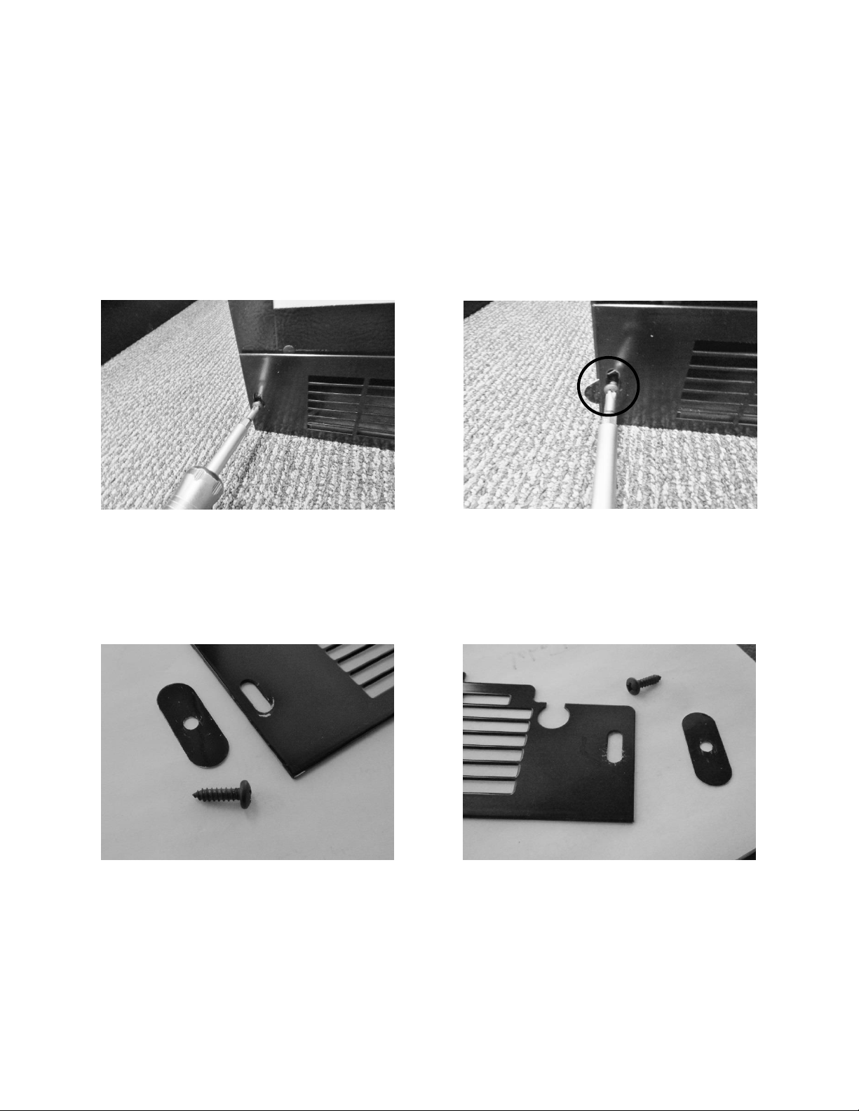
3.1. Toe Grill Removal
1. Remove both Phillips screws on each end of the toe grill.
2. There is an oval spacer held in place by each screw, located behind the toe grill. This is
to help give an aesthetic appearance once the grill is adjusted and tightened.
Remove each Phillip screws on both ends of
the toe grill.
The oval toe grill spacer is visible in the above
picture.
Right and left hand views of the toe grill, screen and spacer.
13
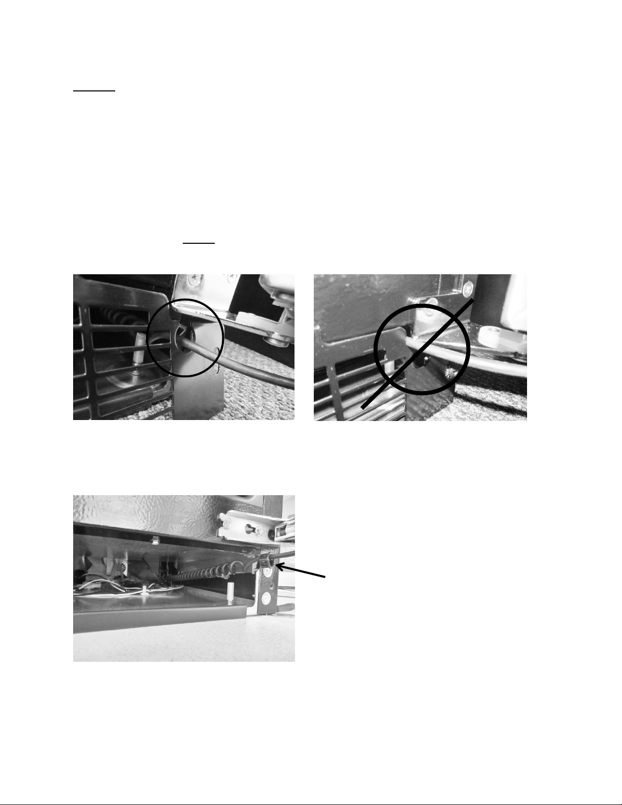
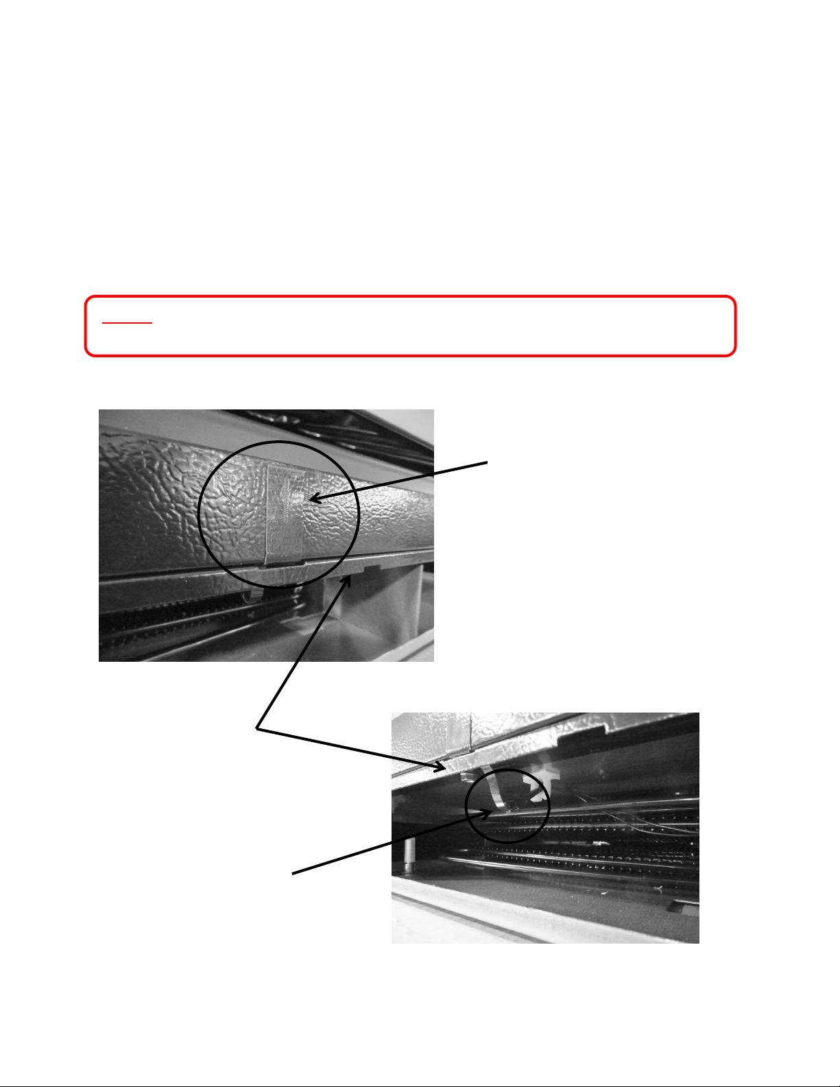
NOTE: When reinstalling the toe grill care must be taken to be sure that the
communication cable is routed through the correct area in the toe grill.
The below left hand photo shows the correct routing of the communication
cable, it must pass freely with clearance on all sides.
The below right hand photo shows the incorrect routing of the communication
cable. It is very easy for the cable to end up in this position if care is not taken
when reinstalling the toe grill. This is a critical pinch spot and will create a service
call in the future with either a frayed or cut cable.
NOTE: Always ensure that the plastic cable grommet is installed
correctly.
CORRECT wire position- Inside grommet.
INCORRECT WIRE POSITION.
Grommet after toe grill
is removed.
14
3.2: Warnings and Cautions
WARNING
Prior to removing the access cover to the machine compartment, disconnect the
supply voltage to the appliance; failure to do this could result in an electrical
shock or possible death.
CAUTION
All electrical parts and wiring must be shielded from torch flame. DO NOT allow
torch to touch insulation; the insulation will char at 200°F and flash ignite (burn)
at 500°F. Excessive heat will distort the plastic liner.
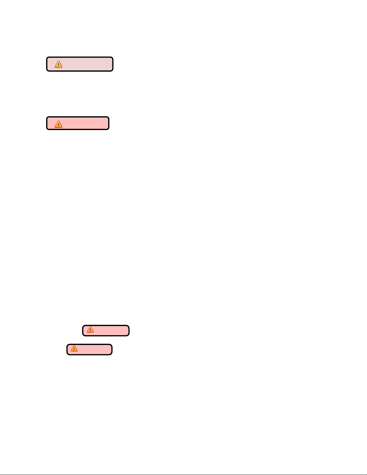
3.3 Accessing the Mechanical Compartment
Access to the mechanical compartment is located at the rear of the unit. Most mechanical and
electrical components on the unit mount directly to the slide out base.
To gain access to the mechanical section proceed as follows, be sure to reference the photos as
called out.
1. For access to the machine compartment remove the screws securing the
compartment panel at the rear of the cabinet.
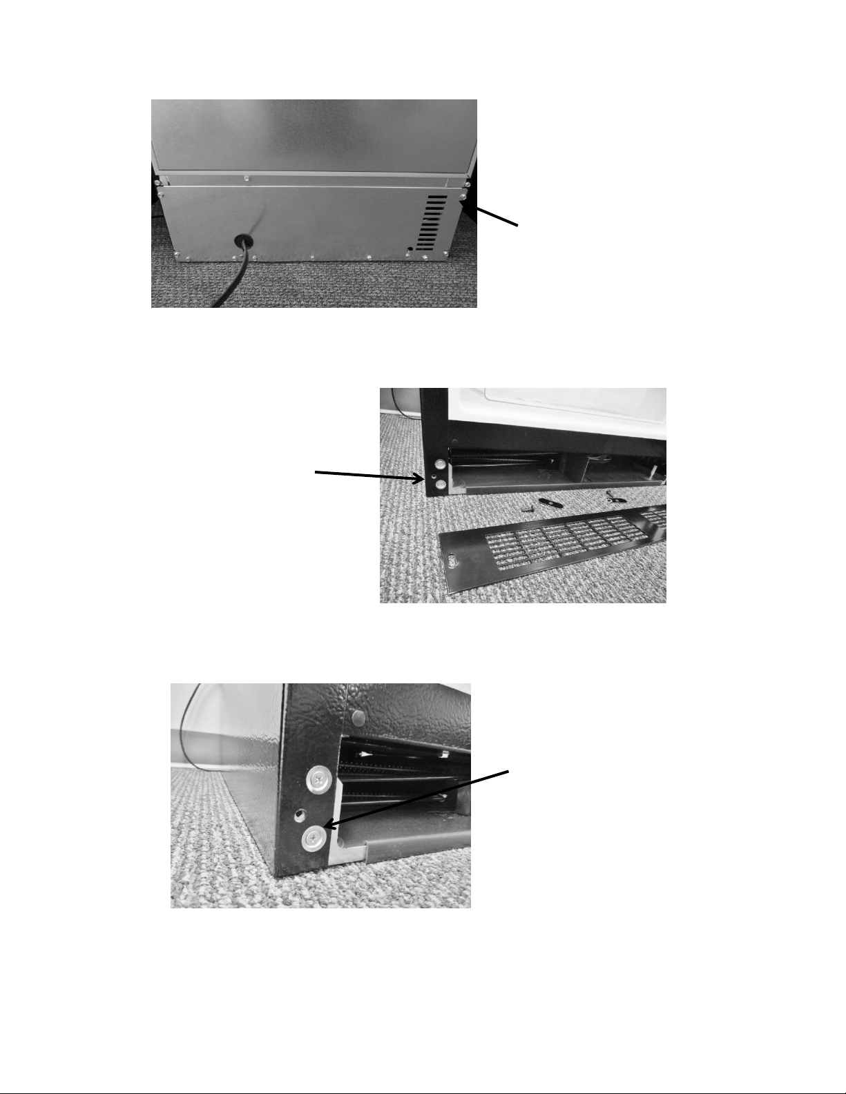
2. For additional service needs it may be necessary to slide the machine compartment
assembly out. Proceed with the following steps.
3. Back out the two Phillips screws (1 on each side) on the toe grill.
4. Once the toe grill is removed, it will be necessary to remove all four screws (two on
each side) to loosen the mechanical assembly from the front.
5. At the rear bottom corner of the unit two (1 on each side) 5/16” hex head screws can
be removed.
6. The mechanical section can now be slid out no more than 2 - 4” maximum until the
suction line has been unsoldered from the compressor*.
WARNING: The refrigeration system must be evacuated prior to unsoldering
the compressor or any other system related component.
7. CAUTION: To avoid kinking the suction line assembly - do not slide the mechanical
base outward past the 4” maximum recommended above.
15
Remove both top
and bottom screws
on each side.
Remove all perimeter 5/16”screws
that secure the back panel – DO
NOT remove the 5/16” hex screws
in the bottom left and right hand
side corners, or the Philips head
ground screws.
Remove both Phillips
screws and grill.
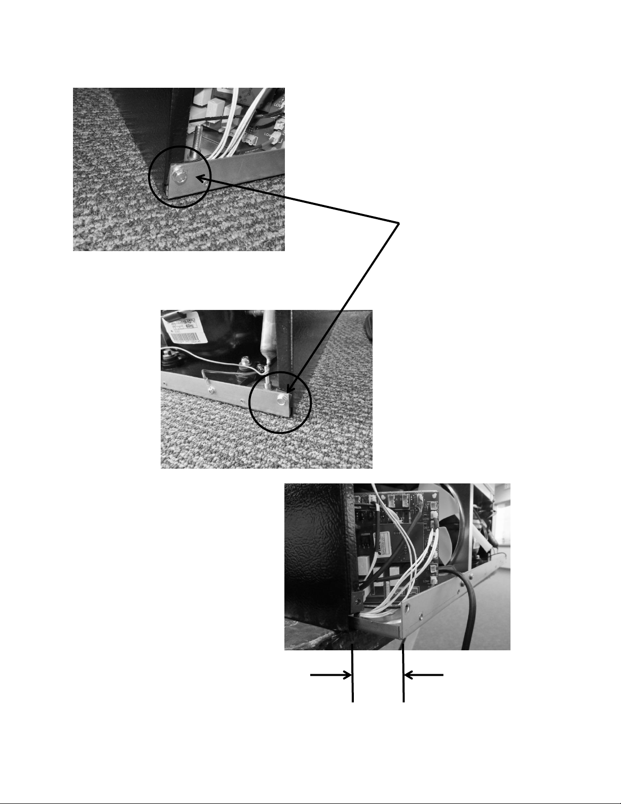
16
Remove both screws.
Maximum distance to
remove bottom of
machine
compartment: 2 - 4”
2 - 4”
17
3.4: Compressor
The following tests should be conducted before concluding the compressor is faulty.
1. Low and high side pressure, temperature of compressor, discharge and suction lines,
temperature of air leaving the evaporator compartment, temperature of condenser
coil, condenser fan operation, and amp draw at compressor.
2. Use a compressor start cord to isolate and test the compressor.
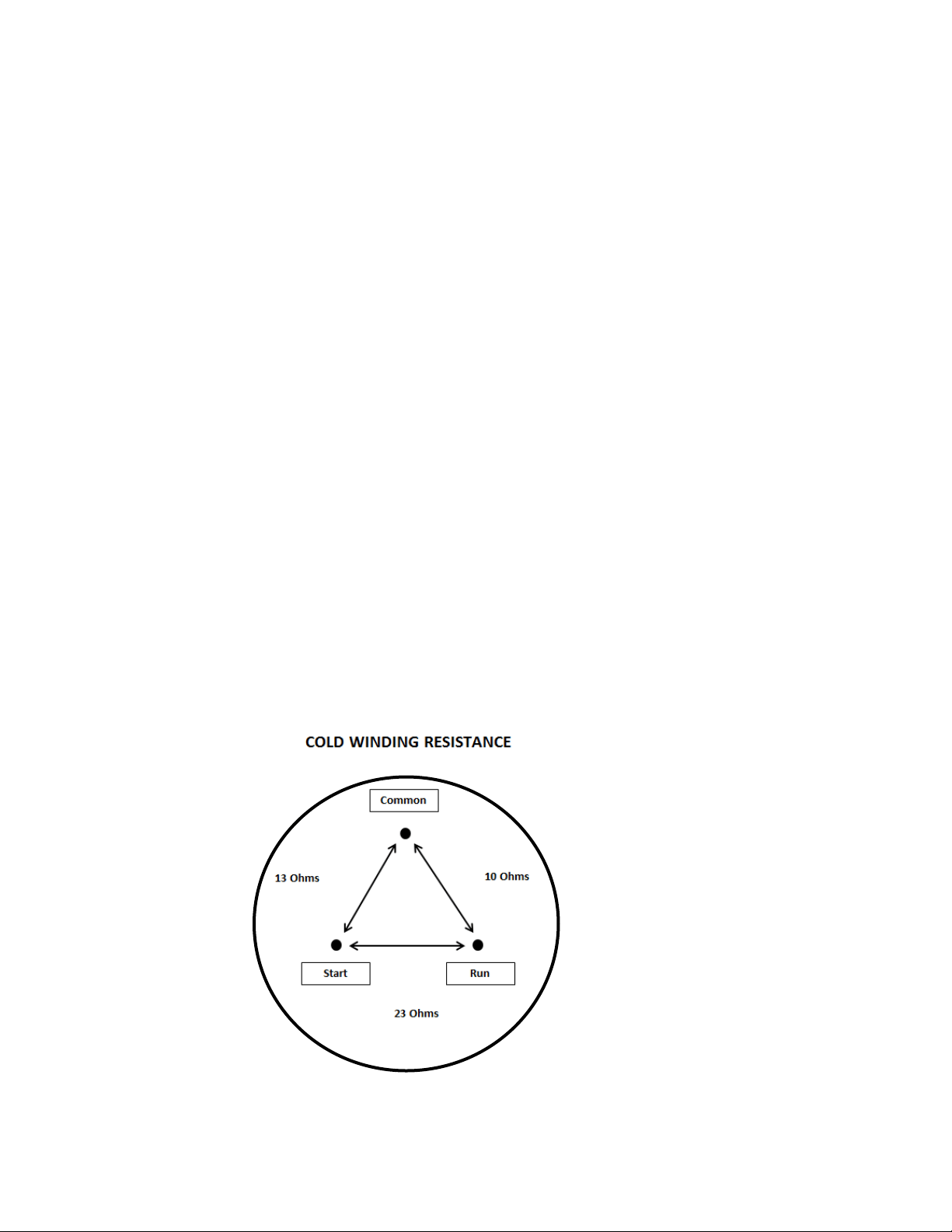
3. Use an ohmmeter to measure resistance / continuity at the compressor to check for
shorted or grounded windings.
a. Resistance between the “Common” and “Run” terminals: this will be the lowest
ohm reading obtained.
b. Resistance between the “Common” and the “Start” terminals: this will be the
mid-range ohm reading obtained.
c. Resistance between the “Start” and “Run” terminals: this will be the highest ohm
reading obtained (This should equal the combined total of the previous two
readings).
d. No resistance between any two terminals signifies an open winding.
e. Check continuity between compressor terminals and the compressor itself
(Scrape off a little paint on compressor to make sure that resistance can be
measured). If continuity is obtained, the compressor is grounded and needs to
be replaced.
3.4.1: Check Compressor Winding Resistance:

18
3.4.2: Remove the Compressor
1. Disconnect power to the unit.
2. Follow the exact steps outlined in “Sealed System Components” to access the
compressor.
3. Using the process tubes, install sealed system access valves and recover refrigerant.
4. Remove the TSD2 starter package from the compressor terminals.
5. Unsolder and remove the discharge and suction lines from the compressor.
6. Unsolder and remove the filter / drier.
7. Cap all refrigeration lines: It is advisable that all exposed refrigeration lines be capped
if the system will be exposed to the atmosphere for any length of time.
8. Remove the three 7/16” nuts, washers and grounding screw from compressor
mounting bolts. There is no nut and washer at the back, left hand mounting position.
9. Lift the compressor off the mounting bolts.
3.4.3: Install a New Compressor
1. Do not remove the rubber plugs from the compressor tubes at this time.
2. Install the four (4) rubber grommets onto the compressor base.
3. Install the three sleeves where the carriage bolts are located.
4. Mount the compressor into position on the mechanical base.
5. Install the three washers and lock nuts and tighten snuggly into place. Do not over
tighten.
6. Install and solder a new filter drier in the system.
7. Remove rubber plugs from compressor tubes.
8. Solder a new process tube to compressor.
9. Solder the discharge and suction lines back into compressor.
10. Re-install TSD2 starter package to compressor terminals.
11. Connect service ports to both the high and low sides of system.
12. Evacuate, charge to serial plate recommendation, and leak check the sealed system.
13. Push the mechanical base assembly back into place.
14. Secure base assembly to cabinet at rear and front locations.
15. Replace the front grill and back panel.
3.5: Condenser
The condenser is of tube and wire construction. It is draw through; forced air technology used
for heat transfer. The front grill facilitates both intake and exhaust air. A fiber board air baffle is
located between the front grill and the rear machine compartment access panel. This baffle
separates the air intake (left hand side) and exhaust (right hand side) across the condenser.
19
A common problem with this system is restricted air flow caused by lint, dust, dirt, and pet hair.
These particles become built up on the condenser and results in overheating due to the lack of
sub-cooling across the coil.
NOTE: Another important factor is that the free air space on the toe grill
cannot be altered to meet a certain design criteria. Any modifications could
jeopardize the integrity of the appliance performance.
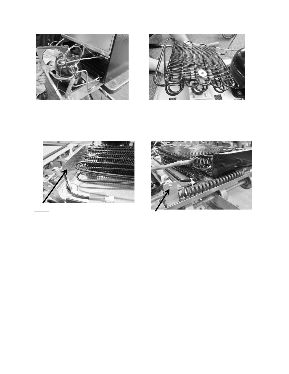
3.5.1: Remove the Condenser
1. Disconnect power to the unit.
2. Follow the exact steps outlined in “Sealed System Components”.
3. Install sealed system access valves and recover refrigerant.
4. Except for the “Data” and the “Communication” cable, all small connections must be
disconnected from the main power board. These two cables will stay with the
mechanical base and removed from the cabinet assembly. In addition the two larger
connectors DO NOT have to be disconnected from the board.
5. Unsolder and remove the filter / drier.
6. Unsolder and remove the discharge and liquid lines from the condenser.
7. Using a 3/8” nut driver or socket, remove (1) 3/8” nut securing each condenser
mounting bracket to the mechanical base.
8. The condenser assembly can now be removed from the base assembly.
9. Use a Phillips screwdriver to remove the condenser brackets from each side of the
condenser. The brackets will slide out once the screws are removed.
10. It is advisable that the un-soldered copper tubes be capped if the system will be
exposed to the atmosphere for any length of time.
Disconnect recommended
connectors.
20
3.5.2: Install a New Condenser
1. If necessary, reattach the mounting brackets to each side of the condenser with the
Phillips screws and washers previously removed.
2. Ensure that the carriage bolts for mounting the condenser brackets are in place on
the bottom of the machine compartment.
3. Install the new condenser with brackets over the mounting studs and secure with the
nuts previously removed.
4. Install and solder the discharge and liquid lines to condenser.
5. Install and solder a new filter drier in the system.
6. Evacuate, charge to serial plate recommendation, and leak check the sealed system.
Slide out the bottom of the machine
compartment far enough to unsolder
condenser lines.
Condenser can be lifted away from bottom
assembly after following step 7 above.
NOTE: On machine compartments with LEFT
HAND SWING doors, a shield is added to
prevent the communication cable from being
drawn into the condenser coil. It is anchored
using the same nut which secures the condenser
mounting bracket.
The above bracket is used on LEFT HAND
SWING doors to anchor the back end of the
communication cable.
21
7. Carefully reconnect all electrical terminals back on the terminal board.
8. Carefully push slide-in mechanical base plate assembly back under cabinet.
9. Secure base assembly to cabinet at rear and front locations.
10. Secure base assembly and toe grill.
3.6: Evaporator
The evaporator removes heat from the inside of the unit ultimately making the interior of the
appliance cold. The evaporator plate is flat in appearance (cold plate) and is installed behind
the coil cover.
It is normal for the evaporator to frost up during its run cycle. This frost will dissipate once the
unit reaches its “cut out” temperature and the compressor and fan stop. This condensate water
will drop off the evaporator plate and down into the tapered sump area formed in the cabinet.
The condensate will then drain down into the compressor condensate pan where it will
evaporate. It is very important that the evaporator frosts in a uniform pattern across the plate.
A partial frost pattern can lead to excessive run times and cooling issues.
Supply air is drawn across the evaporator plate from the evaporator fan and into the cabinet
interior through the supply louvers located at the bottom of the coil cover.
NOTE: Refer to Section 19 for a Service Bulletin regarding the removal of the
Evaporator / Heat Exchanger Assembly.
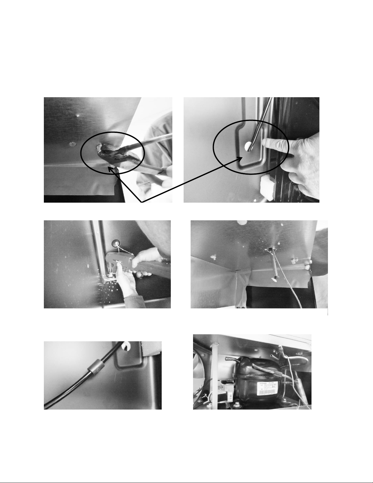
3.6.1: Remove the Evaporator
CAUTION Sharp burrs can result in cuts.
1. Disconnect power to the unit.
2. Use steps in Section 8 for access to evaporator compartment.
3. Follow the exact steps outlined in “Sealed System Components”.
4. Install sealed system access valves and recover refrigerant.
NOTE: The evaporator heat exchanger is foamed in place in the back
cabinet wall.
If an evaporator replacement is necessary, the heat exchanger will have to be cut at
the point it enters the foamed cabinet (behind evaporator plate). The suction line
will also have to be cut at the point where it enters the foamed cabinet from the
machine compartment.
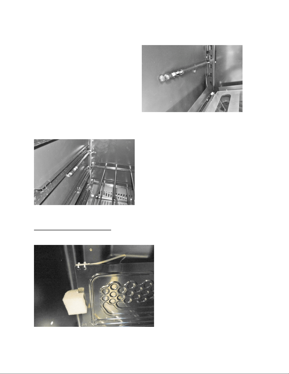
5. Remove the white foam evaporator spacers. Save as they will be used for the new
evaporator assembly.
6. Remove the evaporator and discard, caution of sharp edges from the cut tubing.
7. Unsolder suction line from compressor and discard, again use caution of sharp edges
surrounding cut heat exchanger.
22
8. Remove liquid and capillary lines from filter drier.
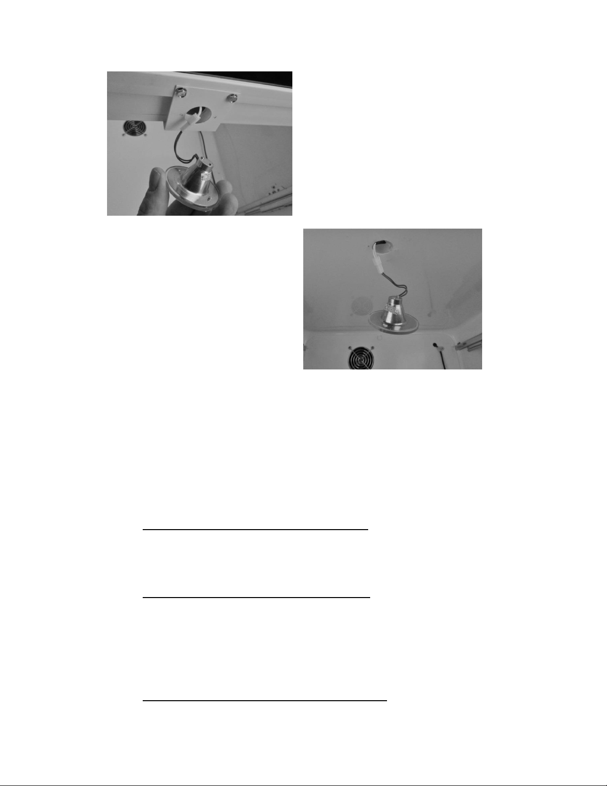
9. Drill a ½” hole in the left hand corner of the drain sump as close to the side wall as
possible. The hole must extend into the machine compartment.
10. Remove any sharp burrs on the roof of the machine compartment created by the
drill bit.
Cut away suction line at the above locations.
Drill a ½” hole downward into machine
compartment. See recommendations in step 9
above.
Extend new assembly through the hole. Make
sure ends are capped.
Install vibration isolator on heat exchanger
assembly behind evaporator.
Cut the suction tube extension to connect the
compressor to the suction line.

23
3.6.2: Install a New Evaporator
NOTE: A replacement evaporator assembly (42249079) will include the
following components:
(1) Evaporator heat exchanger assembly
(1) Filter drier
(1) Pre bent suction tube extension
(1) Vibration Isolator
(2) Nylon zip tie fasteners
(2) Pieces of permagum
1. Take the replacement evaporator and unroll the capillary tube on the heat exchanger.
2. Absolutely make sure that the ends of the capillary tube and suction line are well
capped. Wrap both ends with tape to insure that no foam enter the tubing when
passing it through the ½” drilled hole. Any foam that is allowed in the tubing will
compromise the sealed system.
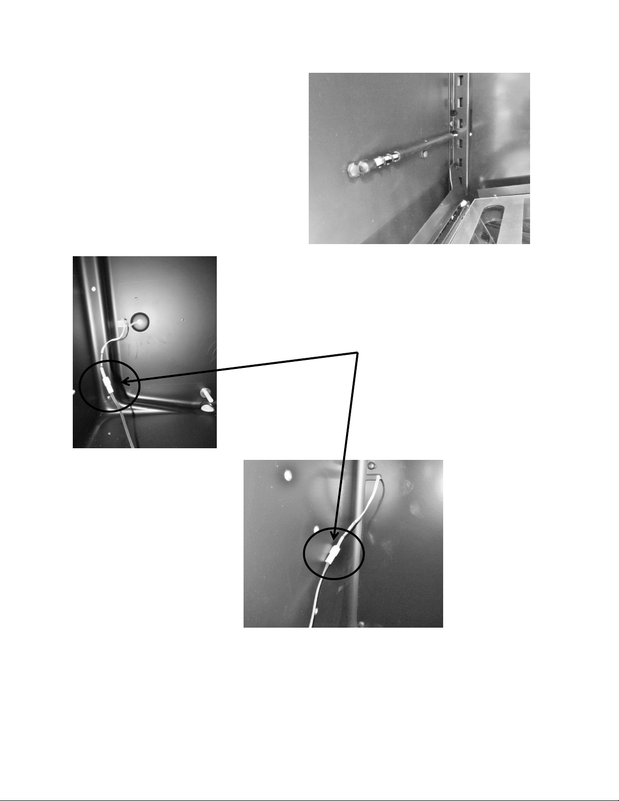
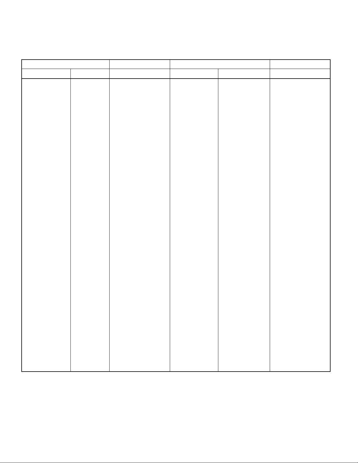
3. Once the new evaporator is in place, the extended suction line into the machine
compartment will have to be bent (thumbs and forefingers) at an angle towards the
compressor.
4. Carefully recoil the capillary tube.
5. Install a new filter drier and solder the capillary and liquid line in place.
6. The kit will include a section of pre-bent suction line. The bent side will be soldered into
the compressor.
7. Use a 3/8”swedging tool to expand the opposite end of the suction extension to fit over
the new suction line extending into the machine compartment. This connection can now
be soldered.
8. Evacuate, charge to serial plate recommendation, and leak check the sealed system.
9. The kit also includes a rubber vibration isolator, place this onto the heat exchanger
behind the evaporator to protect against tube rattles between the evaporator and
cabinet liner.
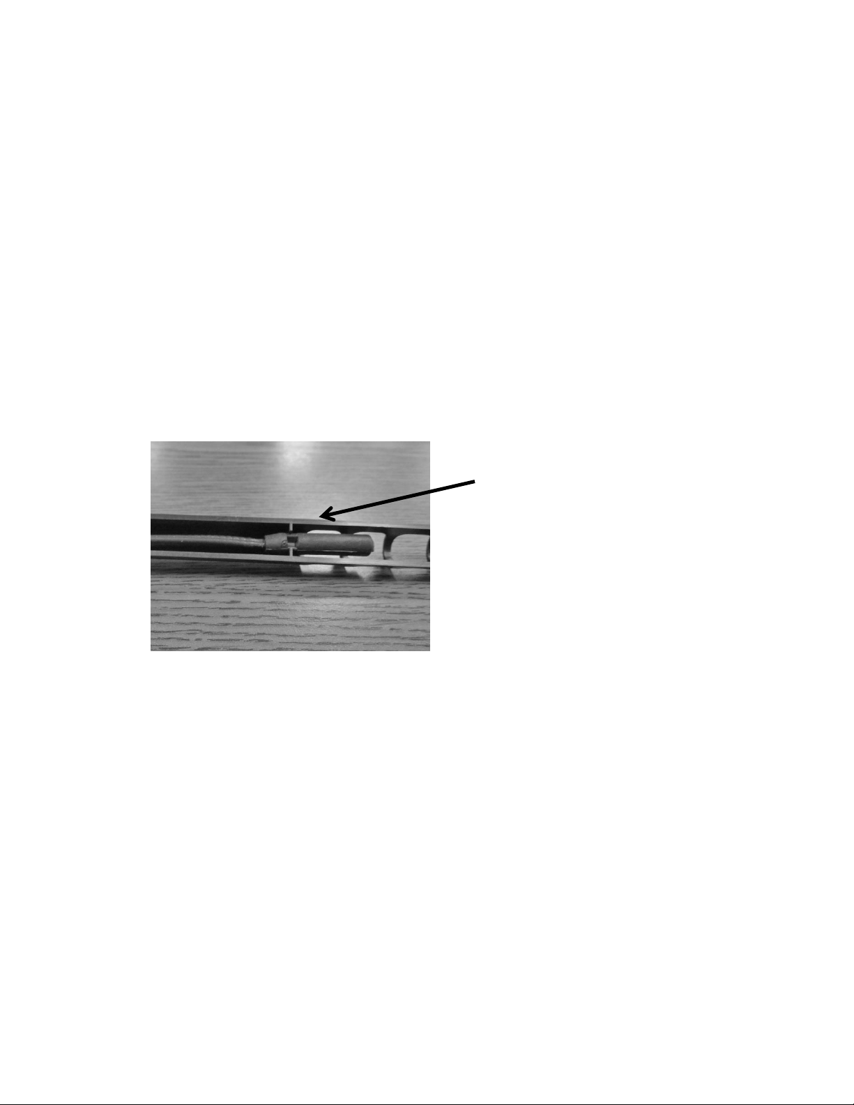
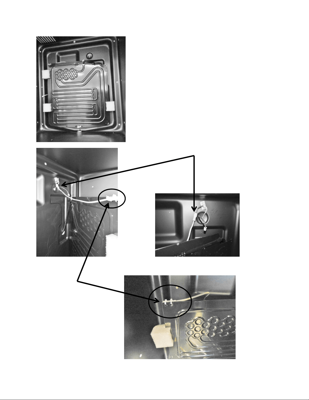
10. Replace the defrost thermistor and attach with the two zip lock fasteners in the kit.
11. Place one piece of permagum around the new evaporator opening in the interior of the
cabinet. Make sure that it is worked into and around the hole to seal off any moisture or
heat.
12. Use the second piece of permagum and also work that into and around the hole in the
machine compartment where the new heat exchanger exits the liner.
13. Re-install the white foam spacers. The spacers have an off center cut on one side, place
the fat side of the spacer (the thickest foam slot) towards the back wall of the liner.
14. Reassemble the coil cover and interior components in reverse order as removed.
15. Reinstall the machine compartment back in place and secure in place at the front and
rear of the cabinet.
24
Section 4: Electrical Component Access
4.1: Condenser Fan
The condenser fan is used to force air over the condenser coil. The condenser fan cycles on and
off simultaneously along with the compressor.
1. Make sure that the motor shaft turns freely. The blade can be turned in either direction
to verify that the shaft is not ceased or the blade binding. Watch the blade and listen for
any noise that might indicate a problem.
2. Check resistance between the terminals of the motors power cord. Replace the motor if
the windings are shorted (open).
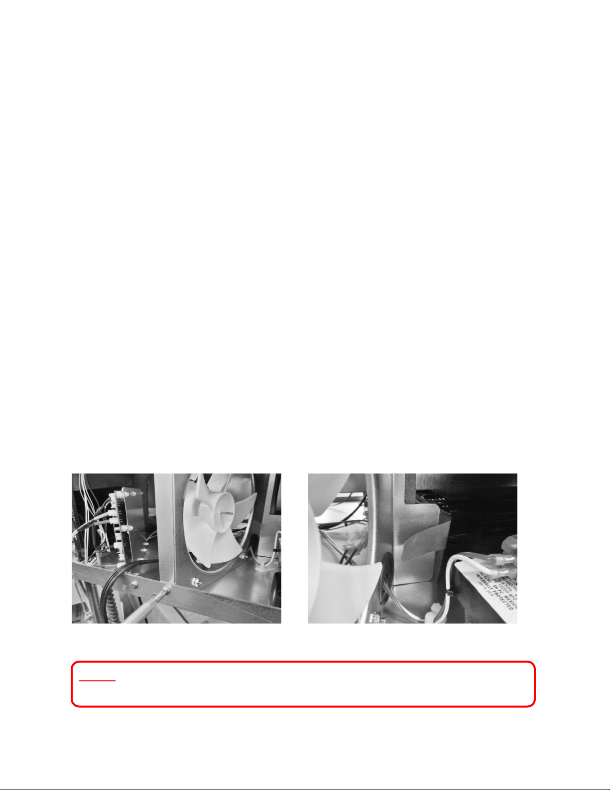
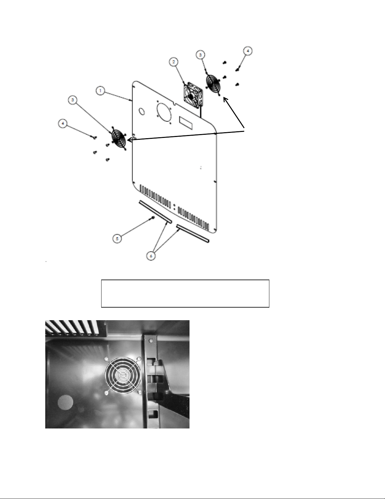
4.1.1: Fan Assembly Removal
1. Remove Phillips head screw securing the condenser fan shroud.
2. Loosen the tape that holds the fiber board divider to the rear of the fan shroud.
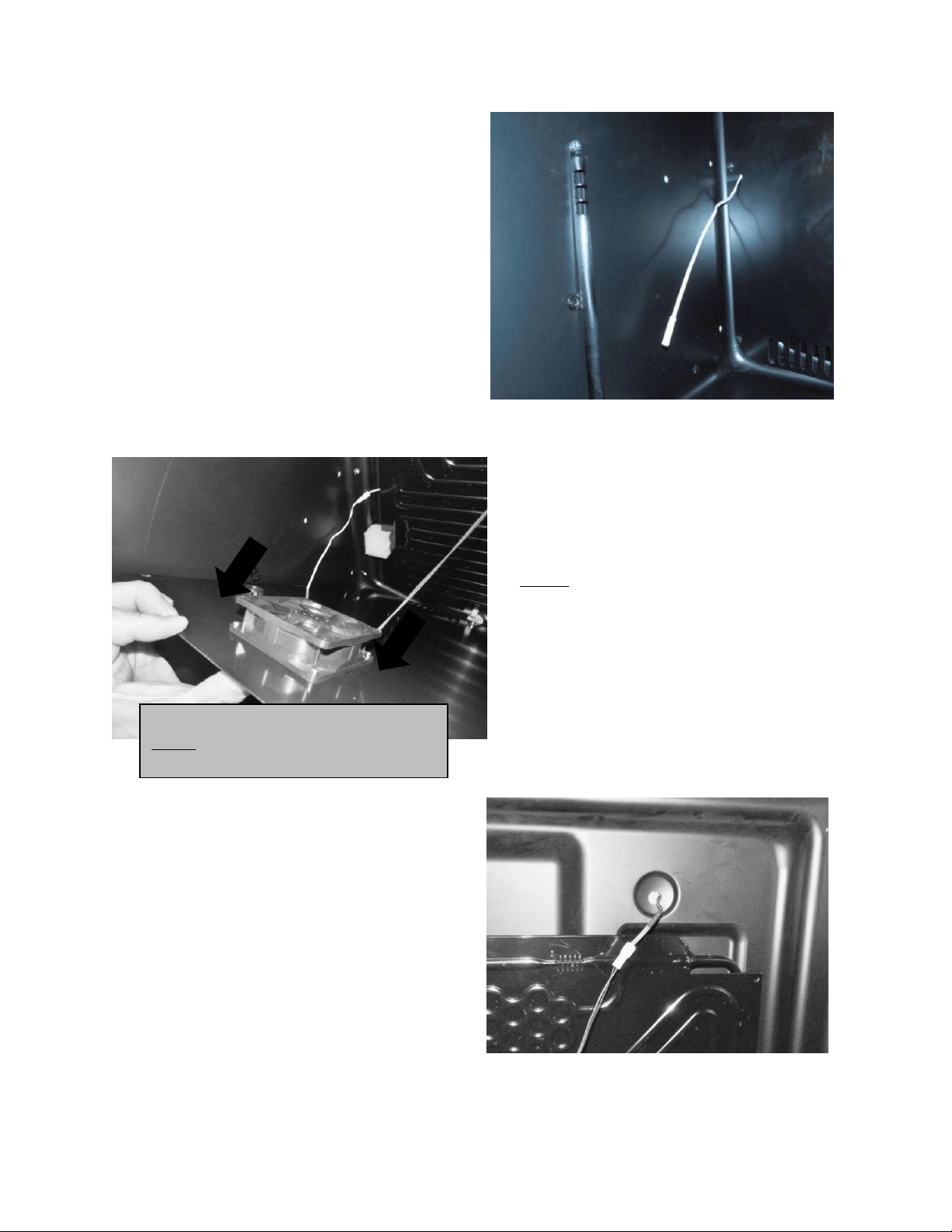
3. Remove the white and red wires attached to the compressor electrical package.
4. Push both the white and red wires all the way though the black perforated plug.
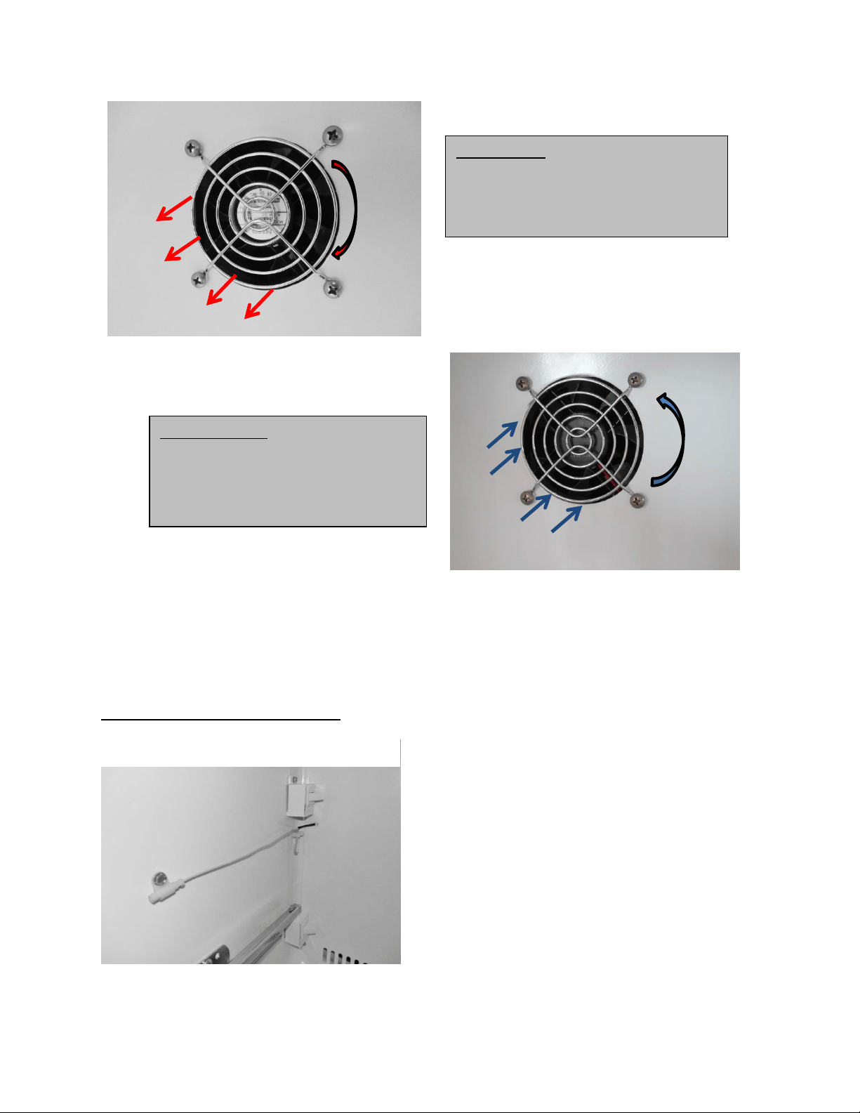
5. Turn the rear of the fan shroud assembly towards your right (clockwise) as far as
possible.
6. Tip the fan assembly forward until it clears the top of the machine compartment.
7. The fan assembly can now clear the mechanical compartment.
8. Disconnect the fan assembly at the connector harness.
Remove bolt and nut.
Loosen tape.
NOTE: Refer to Section 19 for a Service Bulletin regarding the removal of the
Condenser Fan Assembly.
25
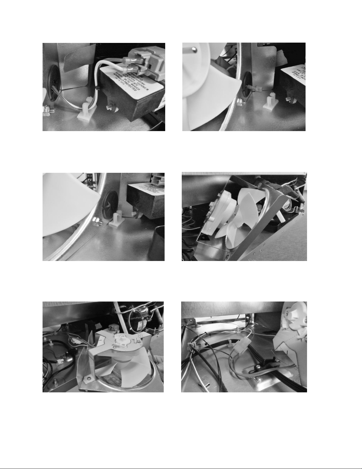
Disconnect red and white wires.
Pull wire through grommet.
Rotate shroud to right.
Tip shroud forward.
Lay shroud flat.
Disconnect connector.
26
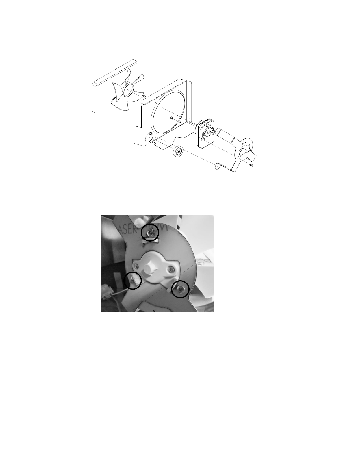
Exploded View of Condenser Fan assembly
4.1.2: Condenser Fan Replacement
1. Remove the three Phillips screws on the rear of the motor bracket to replace fan motor.
4.1.3: Fan Assembly Installation
1. Prior to reassembling the condenser fan assembly locate the slotted tab on the bottom
of the machine compartment.
2. Next locate the notched recess on the bottom of the shroud assembly.
3. Upon assembly, the notched slot on the shroud assembly needs to slide in the slotted
tab on the compartment bottom.
27
4. Once secure, the condenser wire harness along with the white and red compressor
wires can be reconnected and the tape from the fiber board can be reattached to the
fan shroud.
5. Reattach the assembly to the rear using the screw previously removed.
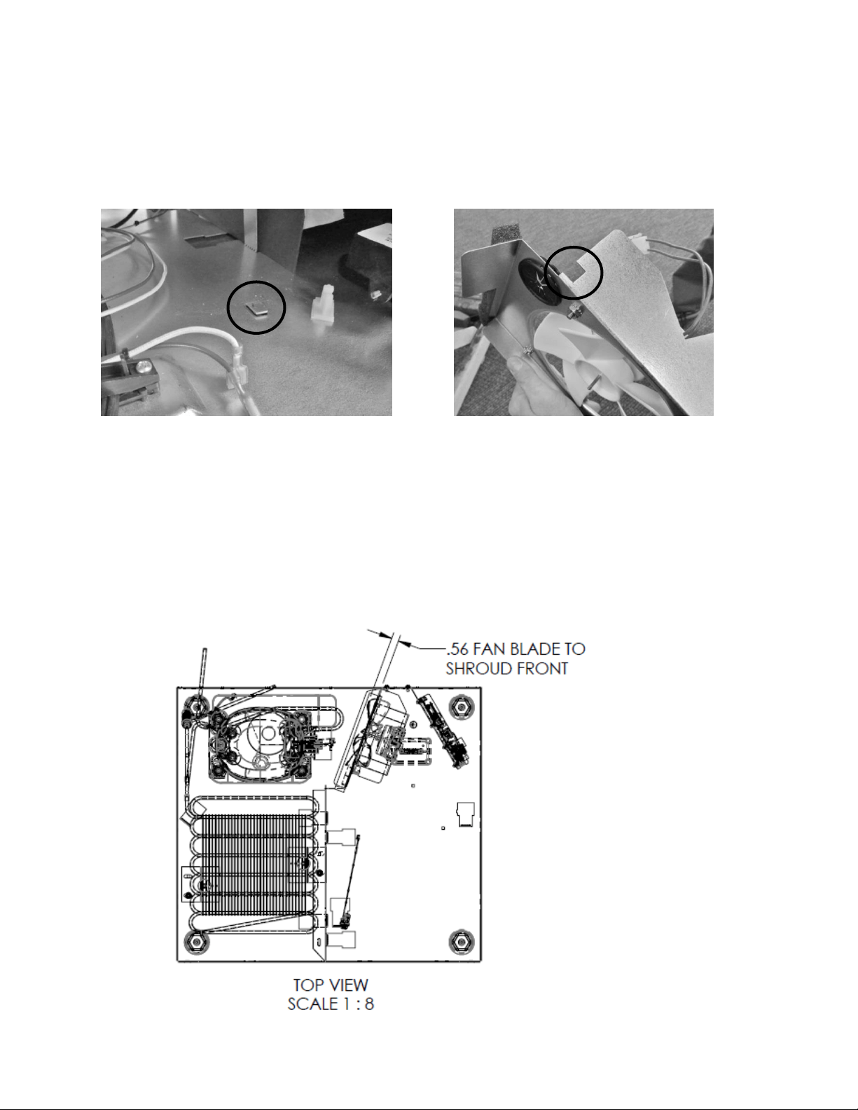
4.1.4: Condenser Fan Blade Spacing
If the condenser fan blade has been removed from the motor shaft the fan blade must be
properly re-spaced to achieve the optimal performance from the condenser.
The correct distance from the tip of the fan blade to the front of the shroud is 9/16” (.56”)
Bracket mounting tab.
Bracket mounting slot.

28
4.2: Evaporator Fan Access
For all models, with the exception of the beer dispenser, the evaporator fan draws air from the
refrigerated space through the bottom supply air louvers, across the evaporator plate, and then
re-distributes it back into the cabinet through the fan itself.
The beer dispenser fan has reversed air flow. The evaporator fan is installed with the writing on
the motor hub facing the rear of the cabinet; this creates a draw through application, pushing
the air downward across the evaporator plate and out the bottom louvers on the evaporator
cover.
To access the evaporator fan, follow the steps below:
1. Remove all shelving.
2. Remove decorative plastic screw caps.
3. Remove screws around the perimeter of the back panel.
4. If the appliance has cantilever shelving, the rails will have to be removed to expose the
screw caps and screws securing the back panel.
5. Additionally with cantilever shelving the rear screw on thermistor shield will need to be
removed as the thermistor is fed through the cantilever bracket.
6. The back panel is slotted mid-way up on the left hand side. This is to accommodate the
thermistor.
7. The rear panel can now be removed.
8. The disconnect plug for the evaporator fan motor is located in the upper right hand
corner.
9. See note on page 28 regarding air flow direction.
NOTE: As of mid-August 2015, a rear fan guard was added to the fan assemblies on the
beverage center models. The fan guard is to eliminate the possibility of wires getting
caught in the fan blade from behind the coil cover.
The approximate serial number range is 20150824xxxH. This is an approximate date and
some variation may be seen in the field.
An exploded view on the following page shows the assembly drawing of the coil cover
components along with both the front and rear fan guards.
29
Fan location – do not attempt to
remove from this view. Remove
coil cover first.
Disconnect all shelving and associated mounting
brackets first – see above instructions
This exploded view drawing shows
the front and rear fan guard. As
mentioned on the previous page, the
additional rear fan guard was added
to outdoor beverage centers and
beverage dispensers to prevent wire
interference.
30
Remove thermistor from
the shield.
Fan assembly attached to rear of coil cover.
Disconnect fan at harness
connection.
Supply Air Flow: Blow through fan type.
NOTE: Beer dispensers have reversed air
flow (draw through).
NOTE: Newer beverage center models made
after 20150824xxxH also have a rear fan
guard.
31
4.3: Thermistor Locations
The following shows typical thermistor locations
Cabinet Thermistor Locations
Refrigerated Drawers
Location: Midpoint on
left hand side wall.
Remove the four screws from the front of
the coil cover to remove either fan.
Most Models: Evaporator Air Flow: Fan is
a blow through type.
Specification label facing forward, the
blade rotates clockwise as you face the
hub.
Beer Dispensers: Evaporator fan (draw
through).
Specification label facing towards rear,
the blade rotates counter-clockwise as
you face the hub.
32
Defrost Thermistor Location
Wine Coolers
Beverage Centers
All Models
Location: Midpoint on
left hand side wall.
Location: Midpoint on
left hand side wall.
Location: Top left hand
corner of evaporator.
.plate
33
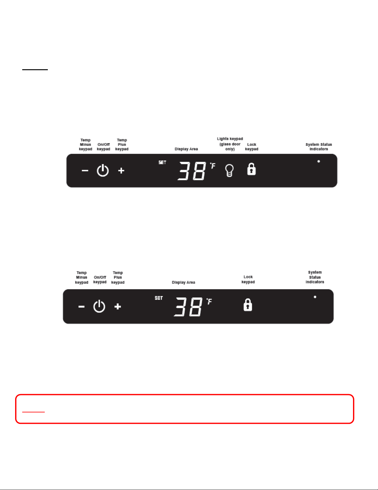
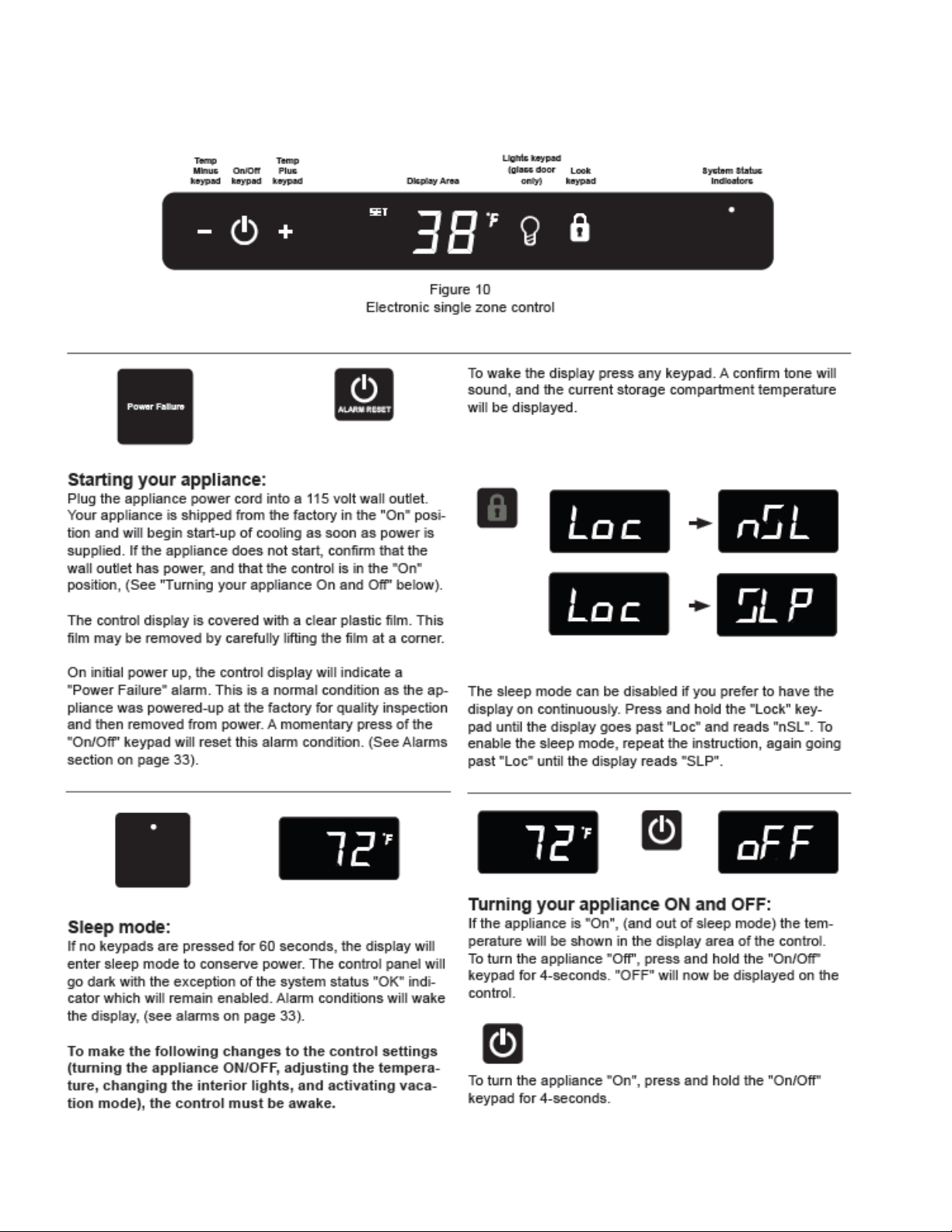
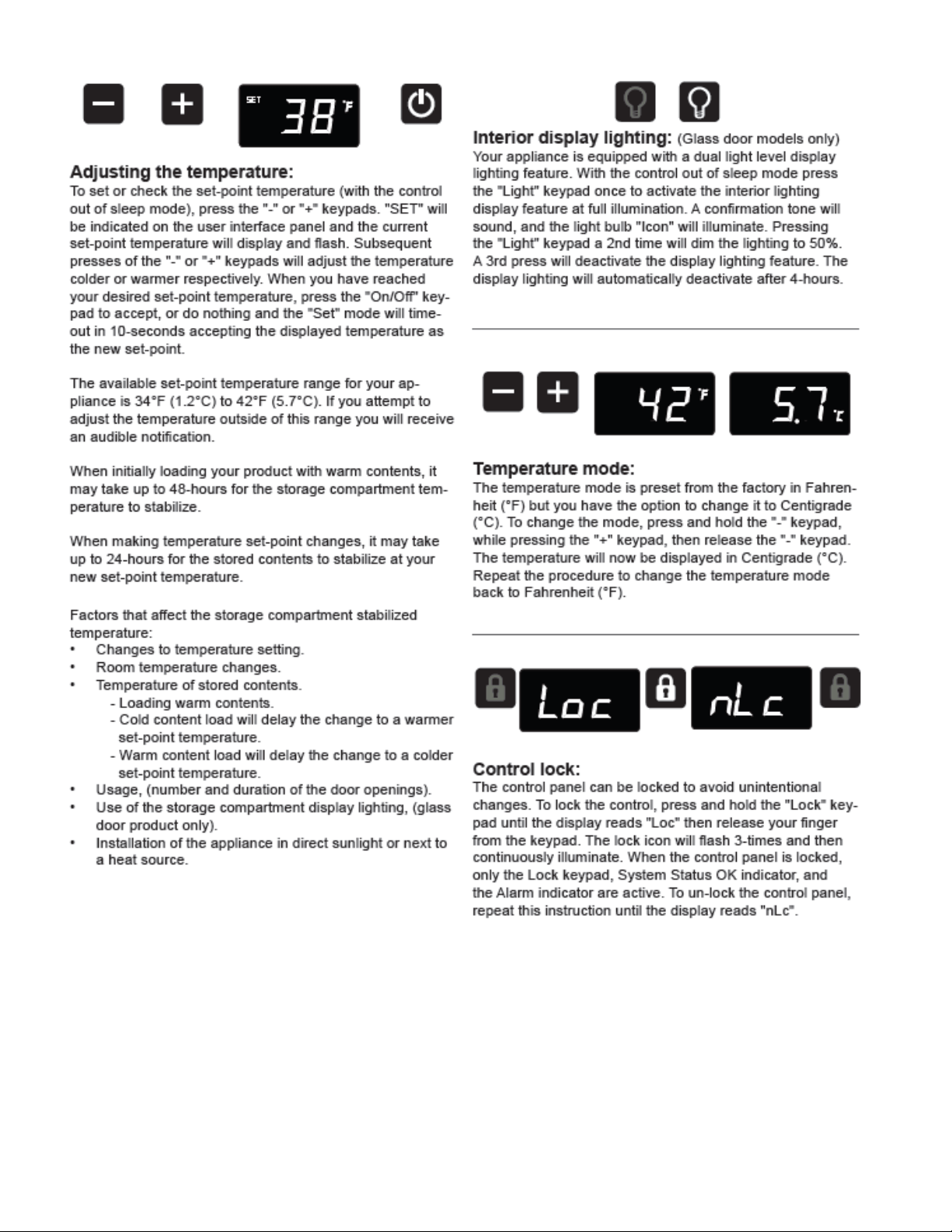
Section 5: User Interface Display
5.1 Model Variations
NOTE: The User Interface Display appearance between the Glass Door and Solid
Door / Drawer models. The Light key is missing on Solid Door and Drawer
Displays.
Glass Door Models:
Solid Door and Drawer Models:
NOTE: Refer to Section 19 for a Service Bulletin regarding an alarm in the Showroom Mode.
34
5.3 User Interface Navigation – Beverage Centers
35
36
37
38
5.4 User Interface Navigation – Wine Coolers
39
40
41
42
5.5 User Interface Navigation – Refrigerated Drawers
43
44
45
5.5 User Interface Navigation – Beer Dispenser
46
47
48
SECTION 6: Control System
6.1 User Interface Display
The user interface display is mounted to the door top and connected to the main power board
by means of a communication cable. The cable extends through the door and exits at the
bottom hinge location.
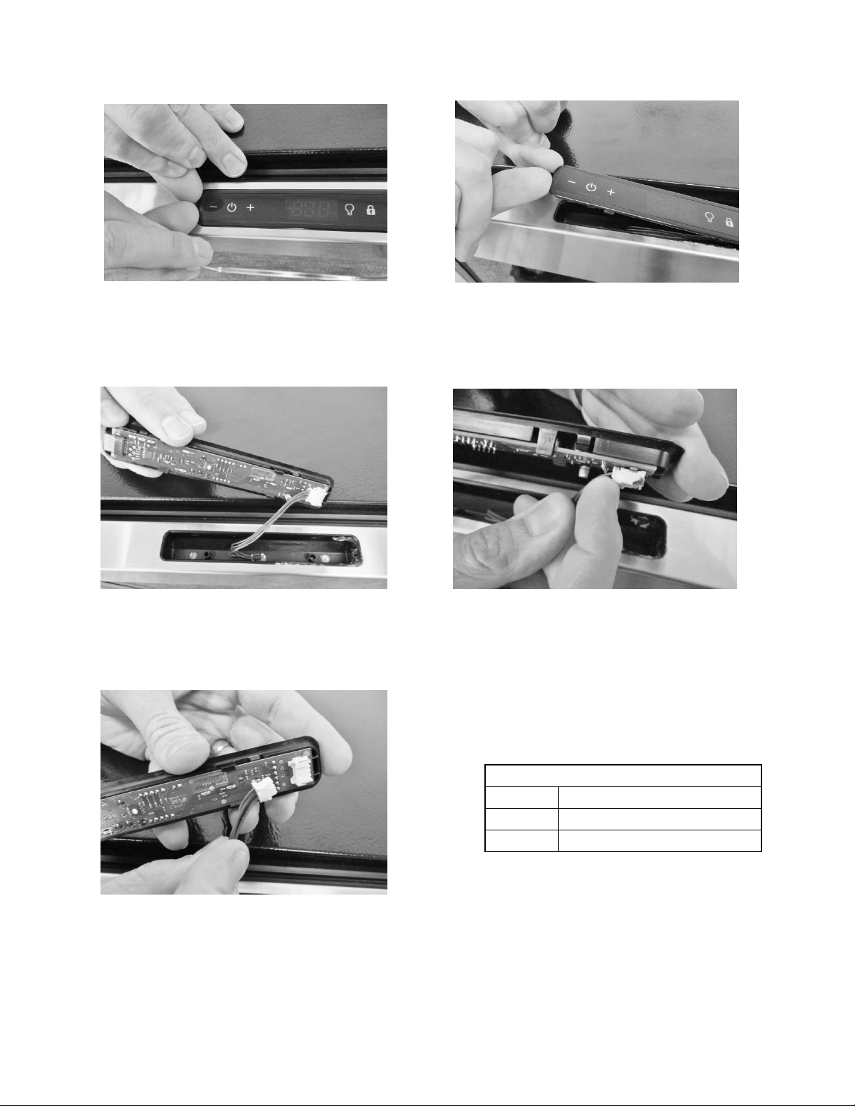
6.1.1 Removing the User Interface Display
CAUTION
It is recommended that a grounding strap be used when working with any
solid state control board application.
CAUTION
Care must be taken as a damaged wire or connector downstream from the
display disconnect connector cannot be repaired or replaced. The Display
receiver and wiring harness are foamed in place. Any damage will result in a
door replacement.
1. Use the bottom edge of both thumb nails to gently pry up on the left hand side
of the display. (DO NOT use a sharp object such as a jack knife, putty knife, or
screwdriver. Objects like these can destroy the appearance of the display or
scratch the door).
2. Once the display is unseated, turn over and locate the display connector.
3. Using your thumb or fore finger to unsnap the lock.
4. Separate the connector and set the display aside.
49
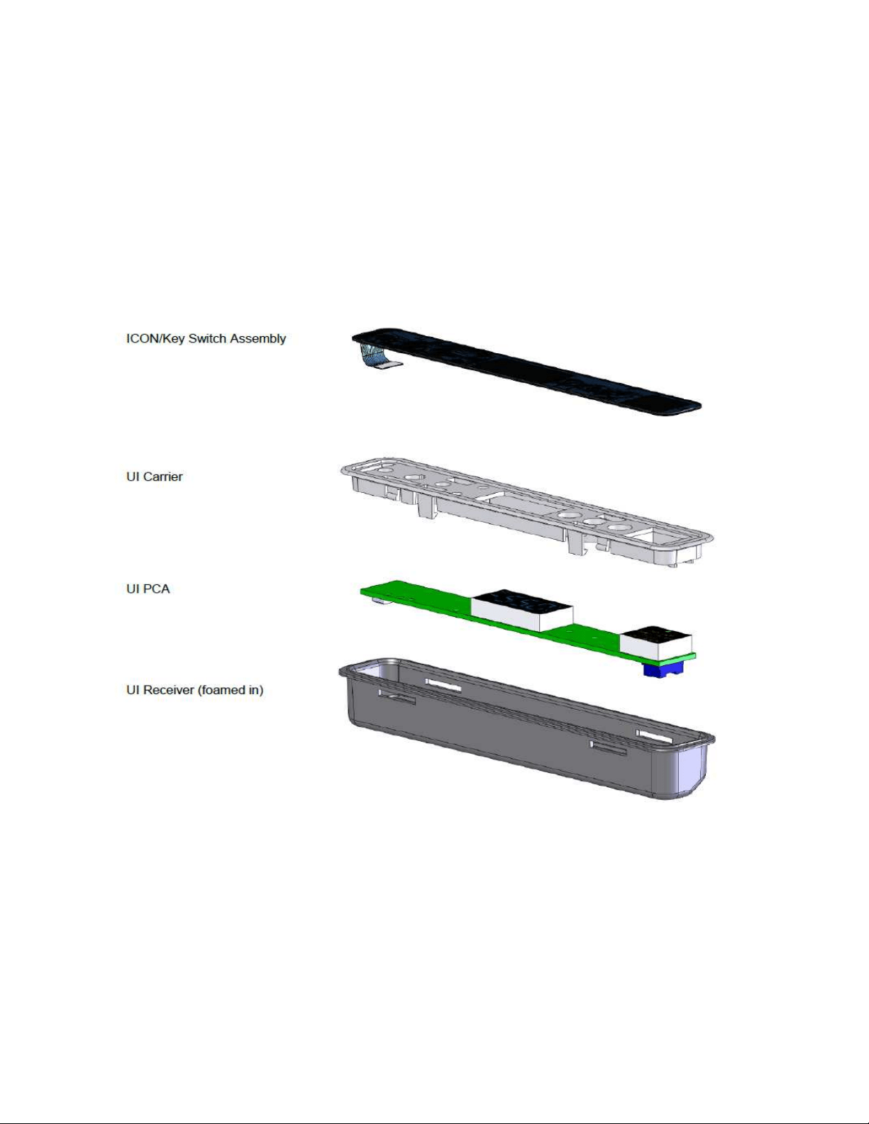
User Interface PCA
Terminal
Description
J1
Com Cable to Main Board
J2
ICON / Key Switch
Lift user interface away from door receiver.
Release locking tab on display connector.
The user interface can now be removed.
Place finger nails under left hand lip of
user interface display.
Lift upwards.
50
6.1.2 Installing a new User Interface Display
1. Reverse the process used to remove the display board.
2. Carefully place the display back into the door receiver.
Apply a light downward pressure to the edge of the display to snap into place
EXPLODED VIEW of User Interface Assembly
51
6.2: Main Control Board
WARNING
Prior to removing the access cover to the machine compartment, disconnect the
supply voltage to the appliance; failure to do this could result in an electrical
shock or possible death.
CAUTION
It is recommended that a grounding strap be used when working with any solid
state control board application.
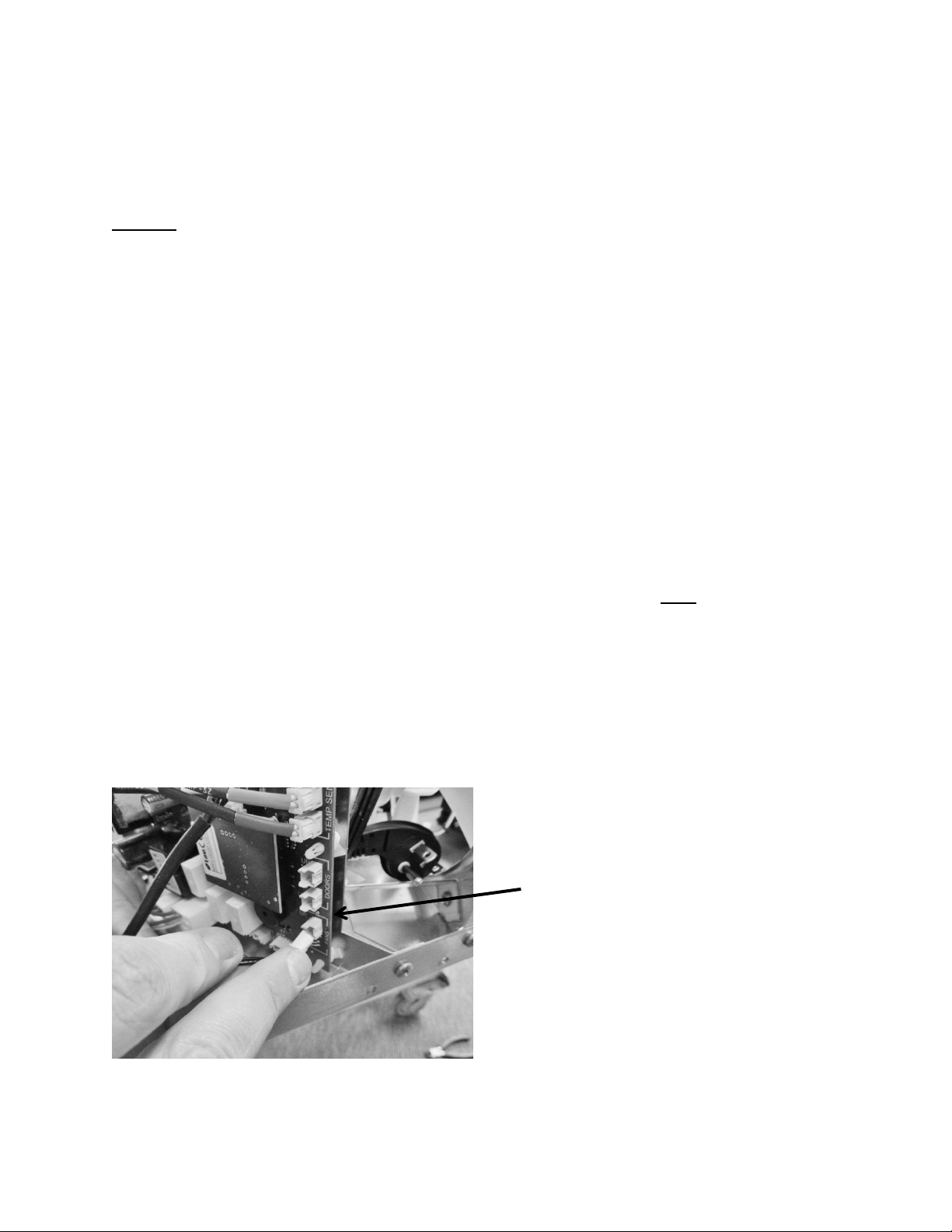
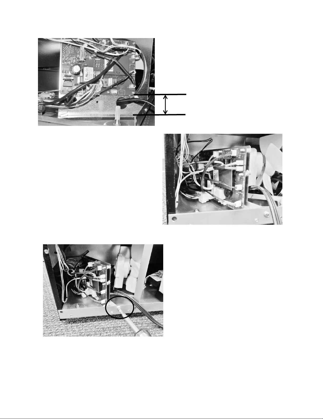
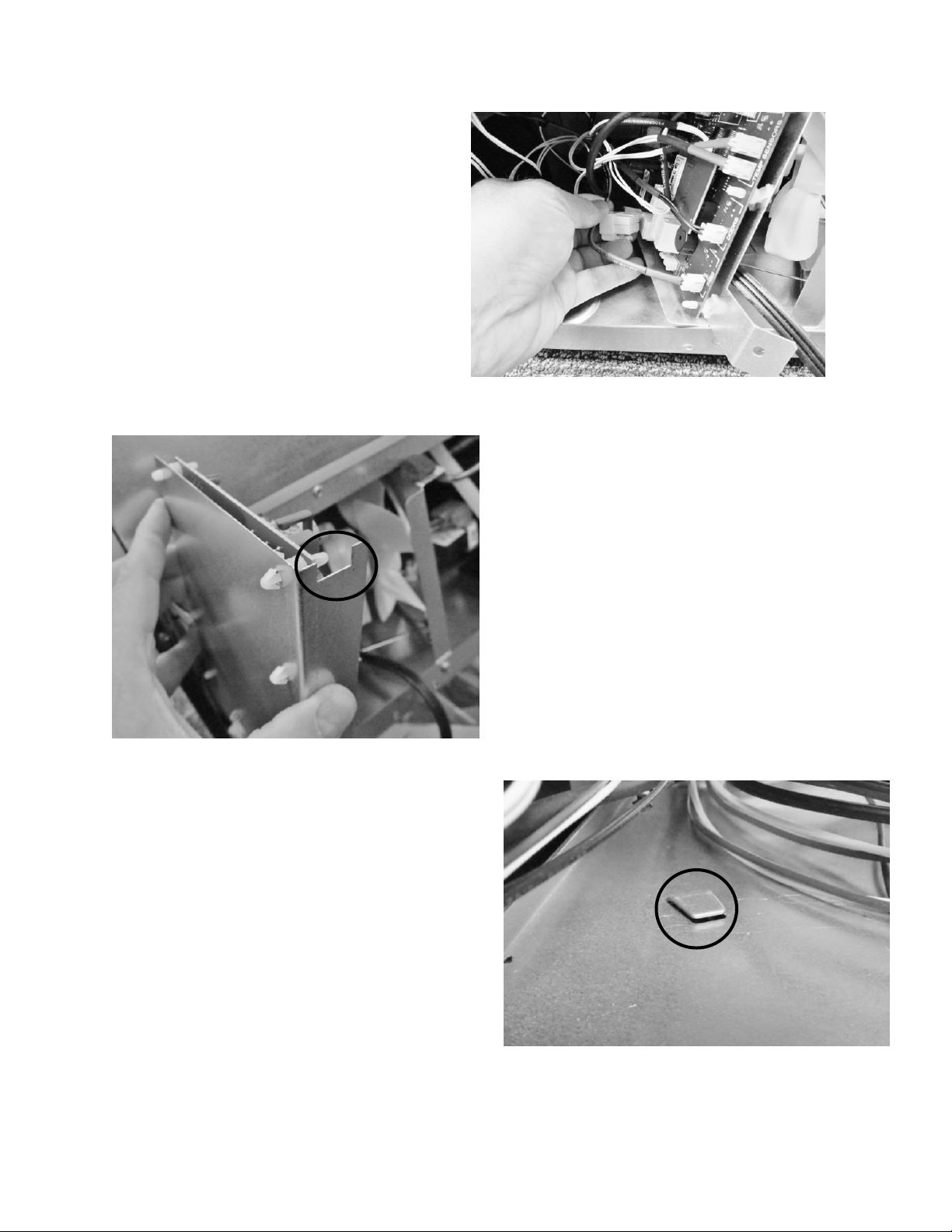
6.2.1: Control Board Replacement
1. The main power board is located at the bottom rear, left hand corner of the machine
compartment.
2. To replace the board, remove the Phillips head screw securing the mounting bracket to
the machine compartment.
3. For ease of access, lower the leveling leg so that the threaded section is lower than its
threaded bushing.
4. Remove both large connectors on the bottom left hand side of the control board. Press
the release and pull each connector off its terminal.
5. The board can now be lifted out of the machine compartment.
6. The main board mounting bracket and the machine compartment bottom are
manufactured for a positive fit upon installation.
a. The control bracket has a notched recess on the bottom rear of the bracket.
b. The machine compartment bottom has a slotted tab to facilitate the recess of
the control mounting bracket when installed.
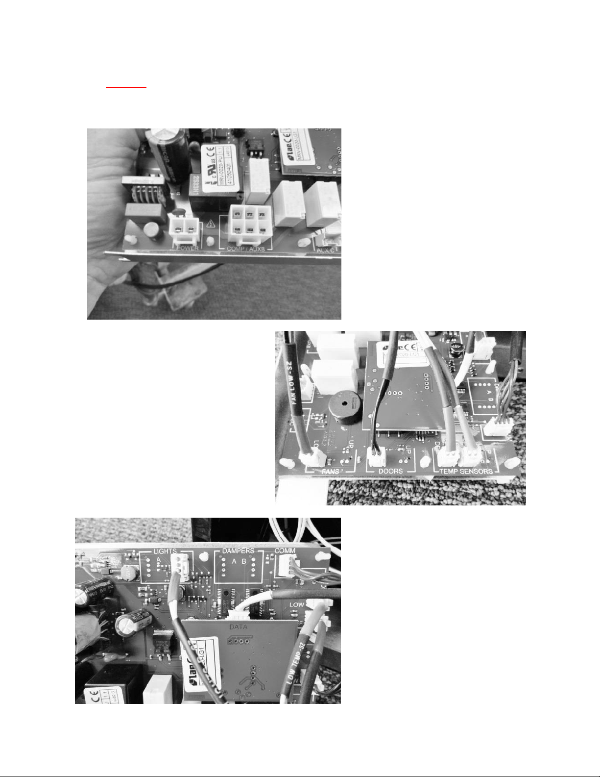
7. Each wiring harness at the board is labeled as to its corresponding location on the
board. Prior to removing any harness, double check to insure that the identification on
each harness is legible for correct placement when repair in completed.
8. The control board terminals are also marked as to the correct harness locations.
52
Remove screw holding
the control board
bracket in place.
Location of the main
power board.
The photo to the left shows the
new modified board bracket to
extend the mounting height farther
away from the cabinet base
.
53
Disconnecting the two
large connectors.
Recess on the bottom of
the mounting bracket.
Slotted tab on the bottom of
the machine compartment.
54
NOTE: For wiring diagrams please refer to: Section 9, Wiring Diagrams.
The following pictures represent terminal identification on a single zone main power board.
Connectors J5 & J15b: See
Wiring, Section 9.1
Connectors J4 – J14: See
Wiring, Section 9.1
Connectors J1 – J9: See Wiring,
Section 9.1
55
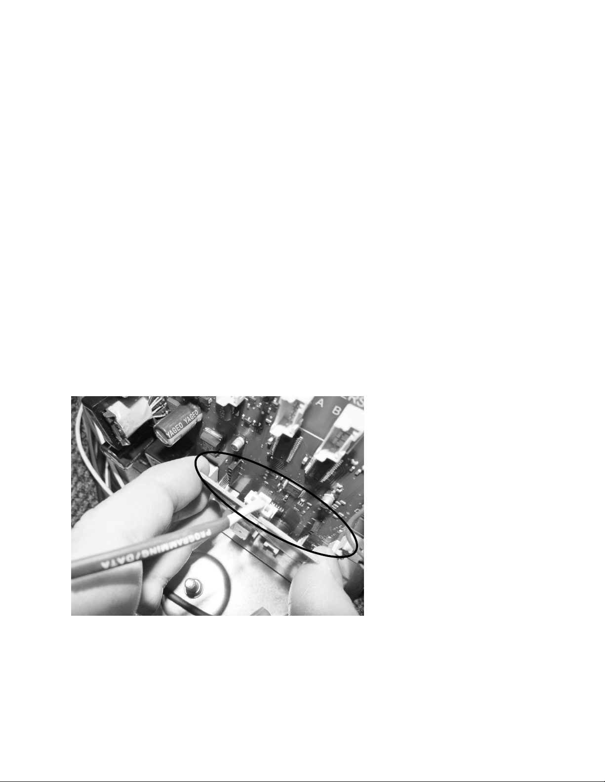
6.2.2: Removing the Programming / Data cable
Care must be taken when removing this cable. The cable is located between the main board
and the small 2” x 2” programming board. It is not recommended to use a metal tool to unsnap
the cable connector. Use of a metal tool could result in a static discharge or accidental damage
to the board.
1. The program board is connected to the main board by a row of pins on each side of the
board.
2. Grasp the program board on each side with your thumb and forefinger. Carefully pull
the program board out and away from the main board.
3. The data / programming cable can now be unsnapped and disconnected.
6.2.3: Re-Installing the Programming / Data cable
1. Carefully replace the data / programming cable back into the connection on the
program board.
2. Once again with care, align the pins on each side of the program board to re-adjoin with
the connections on the main power board.
Connector J16: See
Wiring, Section 9.1
56
6.2.4: Control Board Installation
1. Replace the two connectors, previously removed, to the correct location on the main
board.
2. Prior to reinstalling the power board locate the slotted tab on the bottom of the
machine compartment.
3. Next locate the notched recess on the bottom of the control bracket.
4. Upon assembly, the notched recess on the control bottom needs to slide into the
slotted tab on the machine compartment.
5. Reattach the assembly to the rear machine compartment flange with the screw
previously removed.
Return the leveling leg to its correct position.
6.3: Cabinet and Defrost Thermistors
WARNING
Prior to removing the access cover to the machine compartment, disconnect the
supply voltage to the appliance; failure to do this could result in an electrical
shock or possible death.
6.3.1 Thermistor (Sensor)
The control thermistor senses the interior temperature allowing the control to adjust and
properly display the interior temperature. The thermistor is located at the mid, left hand wall.
The thermistor is covered with a plastic shield to prevent accidental damage.
The thermistor can be checked by use of a multi-meter with the ability to read resistance. Refer
to the resistance chart.
6.3.2: Check the Thermistor:
The main cabinet and defrost thermistor harnesses from the control board are foamed in place.
The recommended method to ohm the thermistor is to remove the thermistor connector at the
control board and take the reading.
For thermistor replacement; the cabinet thermistor connector is located in front of the
evaporator cover, the defrost thermistor connector is located behind the cover.
57
6.3.3: Removing the Cabinet Thermistor
1. Remove interior shelving for ease of access.
2. Remove the decorative caps and screws from the thermistor shield.
3. Remove cantilever shelving brackets if applicable.
4. Disconnect the bad thermistor at the connector plug and remove.
5. For refrigerated drawers:
Remove both top and bottom drawers. See “section 7.4.1” regarding drawer
removal.
6.3.4: Installing the Cabinet Thermistor
1. Snap the new thermistor into the other half of the connector.
2. Place the new thermistor into its protective shield. The underneath side of the shield is
fitted to accommodate the grooves on the thermistor bulb.
3. Replace all components in the reverse order they were removed.
6.3.5: Removing the Defrost Thermistor
1. Remove all interior shelving.
2. Remove cantilever shelving brackets if applicable.
3. Remove decorative screw caps and screws from evaporator coil cover.
4. Disconnect fan.
5. Remove evaporator coil cover.
6. Cut the two nylon zip ties holding the thermistor to the evaporator plate.
7. Disconnect the bad thermistor at the connector plug and remove.
6.3.6: Installing the Defrost Thermistor
1. Snap the new thermistor into the other half of the connector.
2. Secure the thermistor on the evaporator plate using the two nylon zip ties included in
the kit. Insure that the thermistor is mounted with the bulb facing the left hand side
of the liner; pull the zip ties firmly for proper plate sense.
3. Replace all components in the reverse order they were removed.
Cabinet Thermistor: Note the locator
slot inside the thermistor shield. The
grooved thermistor bulb fits firmly in
the seat created inside the shield.
58
Defrost Sensor
Location.
Basic Evaporator
Configuration: All Models:
Evaporator cover removed.
Defrost Sensor Disconnect.
59
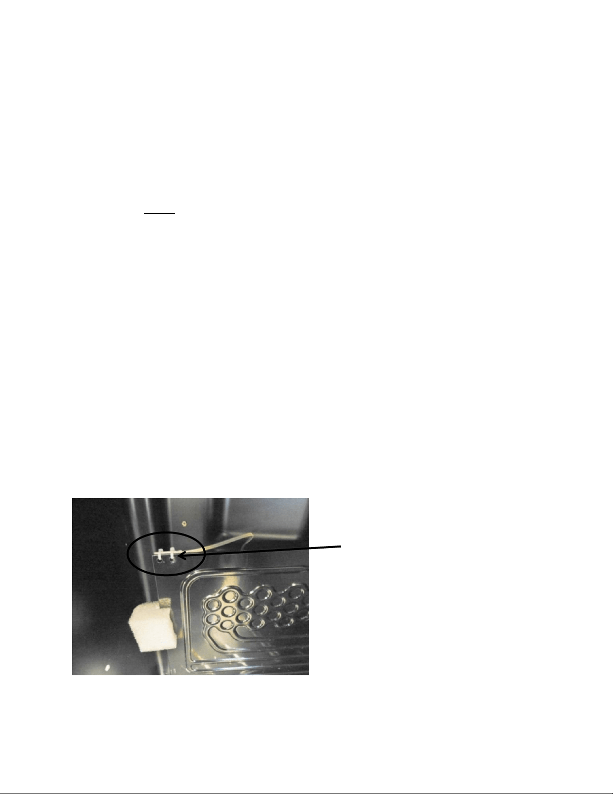
6.3.7: Thermistor Harness Identification:
1. Cabinet sensor, (orange) labeled: “Low Temp”.
2. Defrost sensor, (red) labeled: “Defrost Evap”.
Cabinet sensor connector.
Cabinet Sensor Location:
Typical on all models.
60
6.4: Temperature Resistance Chart
TEMPERATURE
RESISTANCE
TEMPERATURE
RESISTANCE
C°
F°
k ohm
C°
F°
k ohm
-18
0
61.941
15
59
14.675
-17
1
59.032
18
64
13.05
-16
3
56.277
19
66
12.555
-15
5
53.667
20
68
12.081
-14
7
51.194
21
70
11.628
-13
9
48.85
22
72
11.195
-12
10
46.627
23
73
10.78
-11
12
44.519
24
75
10.382
-10
14
42.518
25
77
10
-9
16
40.611
26
79
9.634
-8
18
38.801
27
81
9.283
-7
19
37.082
28
82
8.947
-6
21
35.451
29
84
8.624
-5
23
33.9
30
86
8.314
-4
25
32.427
31
88
8.018
-3
27
31.027
32
90
7.733
-2
28
29.695
33
91
7.46
-1
30
28.429
34
93
71.99
0
32
27.224
35
95
6.947
1
34
26.081
36
97
6.706
2
36
24.992
37
99
6.475
3
37
23.955
38
100
6.252
4
39
22.967
39
102
6.038
5
41
22.025
40
104
5.833
6
43
21.126
41
106
5.635
7
45
20.269
42
108
5.445
8
46
19.452
43
109
5.262
9
48
18.672
44
111
5.086
10
50
17.928
45
113
4.916
11
52
17.216
46
115
4.753
12
54
16.536
47
117
4.596
13
55
15.887
48
118
4.445
14
57
15.267
49
120
4.3
61
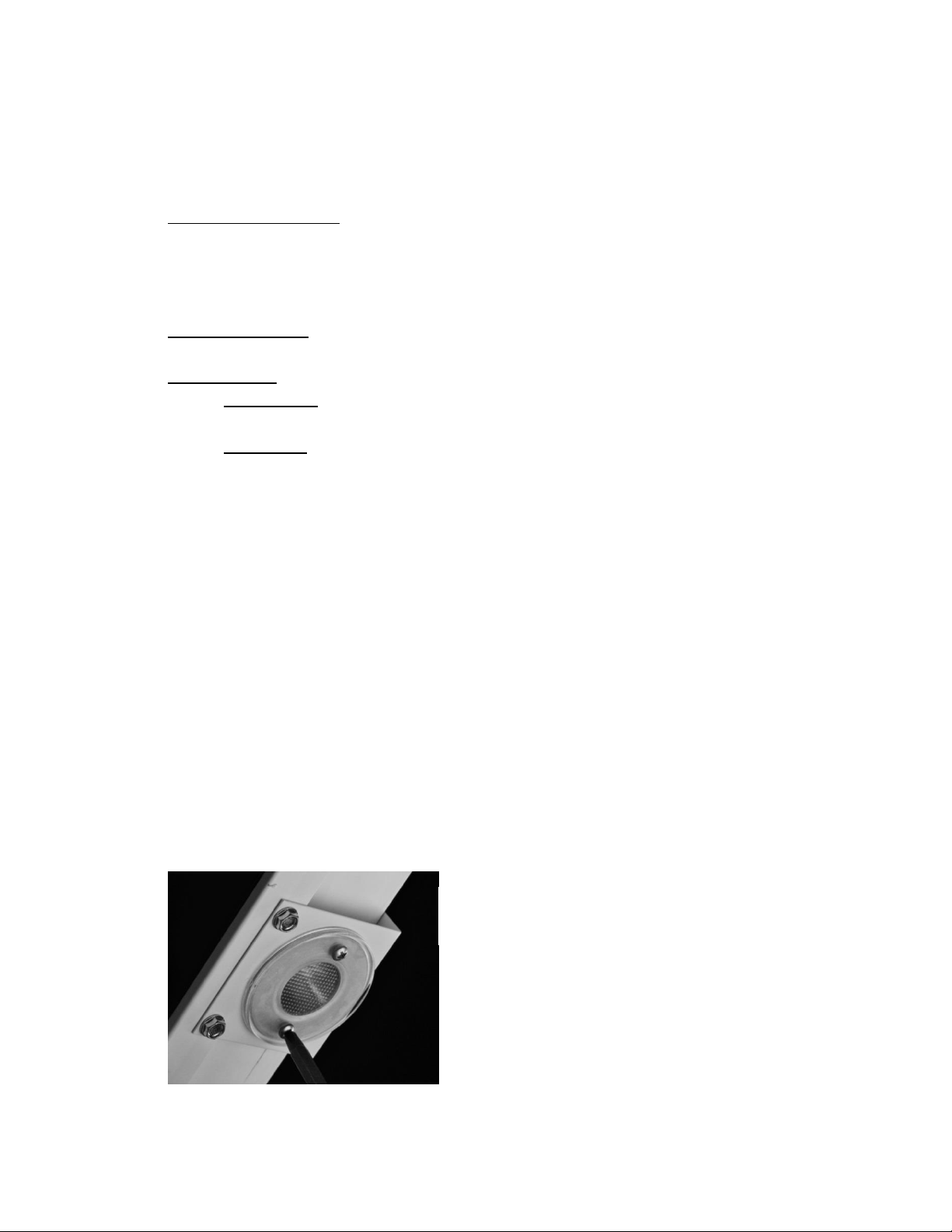
6.5: Door Sensor
On beverage center and wine cooler models, the door sensor is located on the bottom cabinet
flange; approximately one third of the distance away from the handle side of the cabinet. The
refrigerated drawers do not use this technology, dual rocker switches are used for drawer
models.
The door sensor is resistance activated by the pressure of the door gasket. Light functionality
and the door alarm are directly related to this switch.
NOTE: Refer to Section 19 for a Service Bulletin regarding a door sensor “DO”
alarm.
Door sensor location.
Sensor disconnect
terminal .
Cabinet trim piece.

62
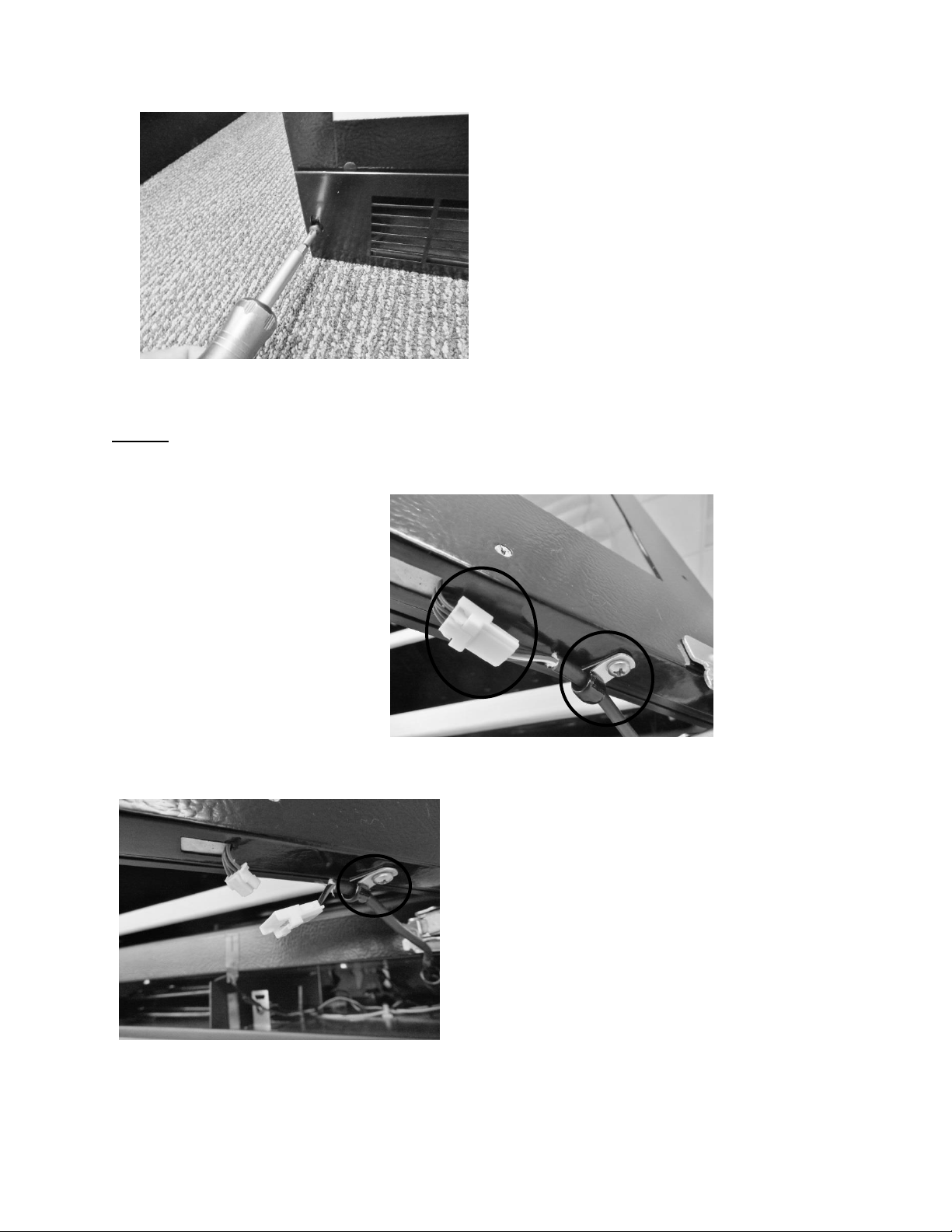
6.5.1: Door Sensor Removal
1. Remove the toe grill.
2. Disconnect the door sensor at the harness terminal behind the trim piece. See photo.
3. Remove the door sensor from the cabinet by starting in one of the upper corners and
peeling in a downward motion.
4. Once the sensor has been removed from the flange area:
a. Grasp the sensor with the right hand using the thumb and forefinger.
b. Grasp the electrical strip portion of the sensor between the thumb and
forefinger on the right hand.
5. Slowly work the sensor through the gap on the lower trim section to remove. The
upper portion of the electrical strip has some adhesive backing so care is advised.
Peel away from cabinet flange.
Sensor removed.
SERVICE BULLETIN 41013995:
Addresses issues with poor door to
switch contact. Available service kits
are: S41050470-BLK, S41050470-
WHT, and S41050470-SS.
Refer to “Service Bulletin Section” in
this manual.
63
6.5.2: Door Sensor Replacement
1. Do not remove the adhesive backing from sensor until it is in place.
2. Slide the new sensor into the gap between the bottom flange and trim piece.
3. Once the sensor is in place:
a. Remove the adhesive backer from sensor.
b. Ensure the sensor is in position and carefully adhere to the cabinet. Apply
carefully using thumb pressure to the outer perimeter of the door sensor.
c. NOTE: Care should be taken not to apply unnecessary pressure directly on the
raised vertical center of the sensor face. The switch is pressure sensitive; any
undue pressure could damage the sensor.
6.6: Defrost Modes
6.6.1: Defrost Characteristics
1. Defrost is achieved as the result of compressor off time. No electrical or mechanical
alternatives are used.
2. Time defrost: Is initiated every 6 hours of compressor run time.
3. The evaporator fan is on for the entire defrost period.
4. Defrost is active for either a period up to 40 minutes of compressor off time or until
the defrost thermistor senses 40°F at its evaporator location.
5. Drip time: The compressor will have an additional 2 minute lag time (30 minutes for
a dual zone) prior to restarting after the conclusion of the defrost cycle. This allows
remaining moisture to drip off the evaporator plate.
6. A manual defrost can be initiated with a two key operation explained in Section
6.6.3
Location of the defrost
thermistor: Top left hand corner
of evaporator plate.
64
6.6.2 Auto Defrost
Drip Time Reference: Dual Zone has been extended to 30 minutes.
Defrost is achieved as the result of
compressor off time. NO electrical or
mechanical alternatives are used.
Timed Defrost: is initiated every 6
hours of compressor run time.
The evaporator fan is on for the entire
defrost cycle.
Defrost is active for a period up to 40
minutes of compressor off time.
The defrost thermistor will terminate
defrost @ 40°F at its evaporator
location.
Drip Time: The compressor will have an
additional 2 minutes (30 for a dual zone)
of lag time prior to restarting after the
conclusion of the defrost cycle. This
allows the moisture to drip off the
evaporator plate.
The defrost will
terminate when
either condition
is achieved prior
to the other
Defrost Time Out
periods edited on
page 64

65
Defrost Time Out (DTO) is the total time of compressor off time; including both defrost and
drip time cycles.
AS OF 8/1/15 THE FOLLOWING CHANGES WERE MADE TO THE DEFROST TIME OUT (DTO) ON
THE FOLLOWING MODELS:
On all models except for the RF, RI, DZ and ML24WS; the DTO was expanded from 60
to 75 minutes.
Model ML24WS was expanded from 40 to 75 minutes.
RF, RI, and DZ models remain the same.
6.6.3 Manual Defrost
A manual defrost can be activated by using the following sequence:
Press the LOCK and MINUS key simultaneously and hold for 3 seconds.
The display will flash dEF (defrost mode) three times before entering the
defrost mode.
dEF will be displayed for the duration of the defrost cycle.
The defrost cycles will terminate when either of the following conditions are
achieved first:
o the defrost has been active for 40 minutes
o the defrost thermistor reaches 40°F
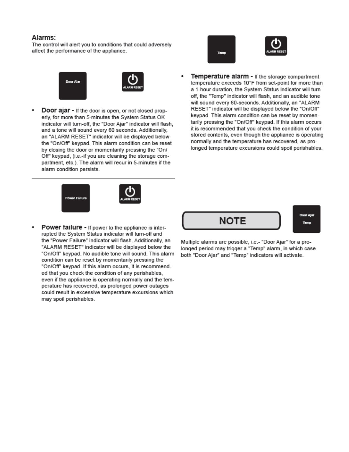
6.7 Error Codes
With the Aurora control there are four error codes that could appear on the user interface
display. They are as follows:
EL : Compartment thermistor open or out of range
Ed : Defrost thermistor open or out of range
EL / Ed : Multiple thermistor errors, open or out of range
CE : Communication cable error, broken connector pin or wire
66
Section 7: Lights, Doors, Drawers, and Hinges
7.1 LED Lighting
1. Refrigerated Drawers: are equipped with two LED lights. The upper LED is located on
the ceiling of the cabinet, while the lower LED is located on the underside of the mullion
assembly. These lights are controlled by the opening and closing of the associated
drawer. Each light is controlled by an independent rocker switch, which is located
behind each drawer on the back wall of the cabinet.
2. Beverage Centers: Have two LED lights and are located on the right hand and left hand
front of the cabinet ceiling.
3. Wine Coolers:
Single Zone: Have two LED lights which are located on the right hand and left
hand front of the cabinet ceiling.
Dual Zone: Same as the single zone with two additional LED lights on the center
divider in like positions as the cabinet ceiling.
The LED lighting for beverage centers and wine coolers is controlled both by the light switch on
the user interface display and also by the read switch mounted on the bottom flange of the
cabinet. Pressure from the door gasket makes and breaks the read switch circuitry to control
light function with door openings and closings.
Additional lighting features can be reviewed in the controls operation section in this manual.
7.1.1: Replacing the LED Light
1. Remove both Phillips screws in lens cover, the LED assembly can now be removed. (A
refrigerated drawer mullion is used for reference in below photo).
2. Disconnect the connector plug to replace LED.
3. Reverse process to install.
Refrigerated drawer mullion
shown in photo.
67
7.2: Cabinet Door
7.2.1 Door Removal
Remove both Phillips screws holding the toe grill in place; one on each end of the grill.
Locate and disconnect the communication cable connector on the bottom of the door
(hinge side).
Remove the P-clamp securing the communication cable to the door bottom.
7.2.1.1 Marvel Models and non-Overlay door Models (Standard Hinge and Pin
Assembly)
Remove the upper door pin with a 1/8” Allen wrench.
Lift the door off the bottom hinge pin.
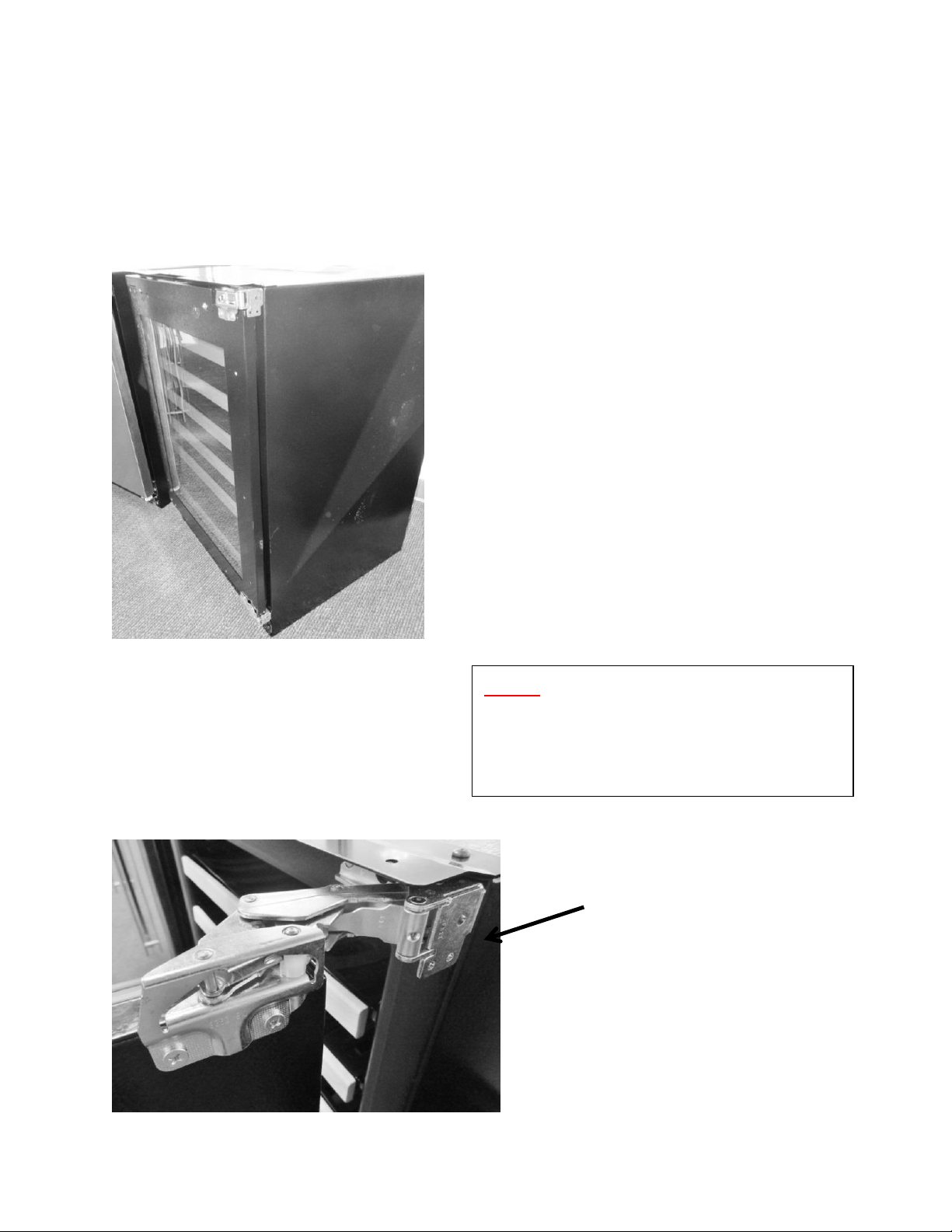
7.2.1.2 Marvel Professional and Overlay Door Models (Articulating Hinge Assembly)
Open the door and locate the 4 mounting screws holding the hinge to the
cabinet flange face.
Loosen both screws in the keyhole and slotted screw holes on the top and
bottom hinges.
Slide the door off the top and bottom hinges.
SEE SECTION 7.7 FOR ADDITIONAL INFORMATION
Cabinet ceiling LED – all
models.
Refrigerated Drawer
Mullion.
68
NOTE: The communication cable is secured to the bottom of the door by the
use of a p-clamp. It relieves in stress applied to the electrical disconnect.
Remove the toe grill.
Communication cable disconnect on
the bottom of door. The p-clamp is
mounted on a post to accommodate
hinge clearance.
Disconnect communication connector
and remove P-clamp and post.
69
7.2.2 Bottom Door Closer
The bottom door closer can be replaced by loosening the screws on both the lower cabinet
flange and the underside of the door.
Remove upper door pin.
Remove screws to replace the door
closer assembly.
70
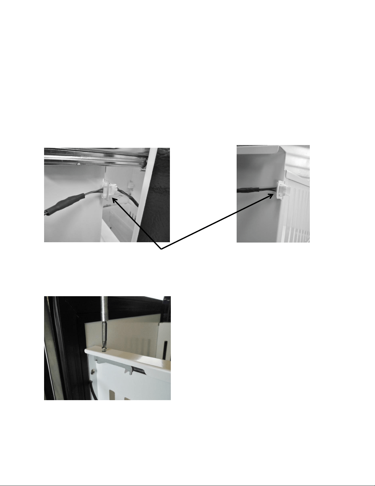
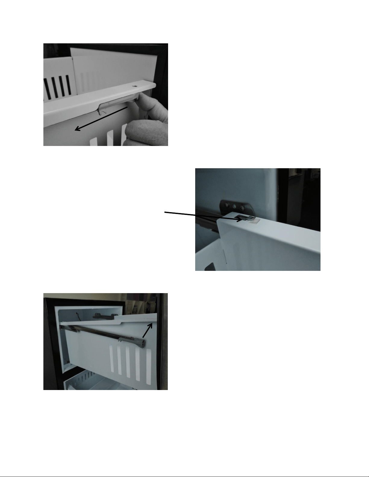
7.3: Refrigerated Drawers
7.3.1: Drawer Removal
1. Disconnect user interface connection located at the top rear on the right hand side of
the upper drawer. (No connections for bottom drawer).
2. Remove the screw on each on top front of each shelf rail (2 total).
3. Push the release rod forward; this will disengage the locking tab on the rear of each
drawer rail.
4. The drawer can now be lifted and removed from the slide rails.
Disconnect communication cable at
right rear of upper drawer.
Remove screw on each side of
shelf rail.
71
Push the gray drawer release, on each
side, forward to unlock drawer tab.
Locking tab shown in secure
position.
Drawer can now be lifted
and removed.
72
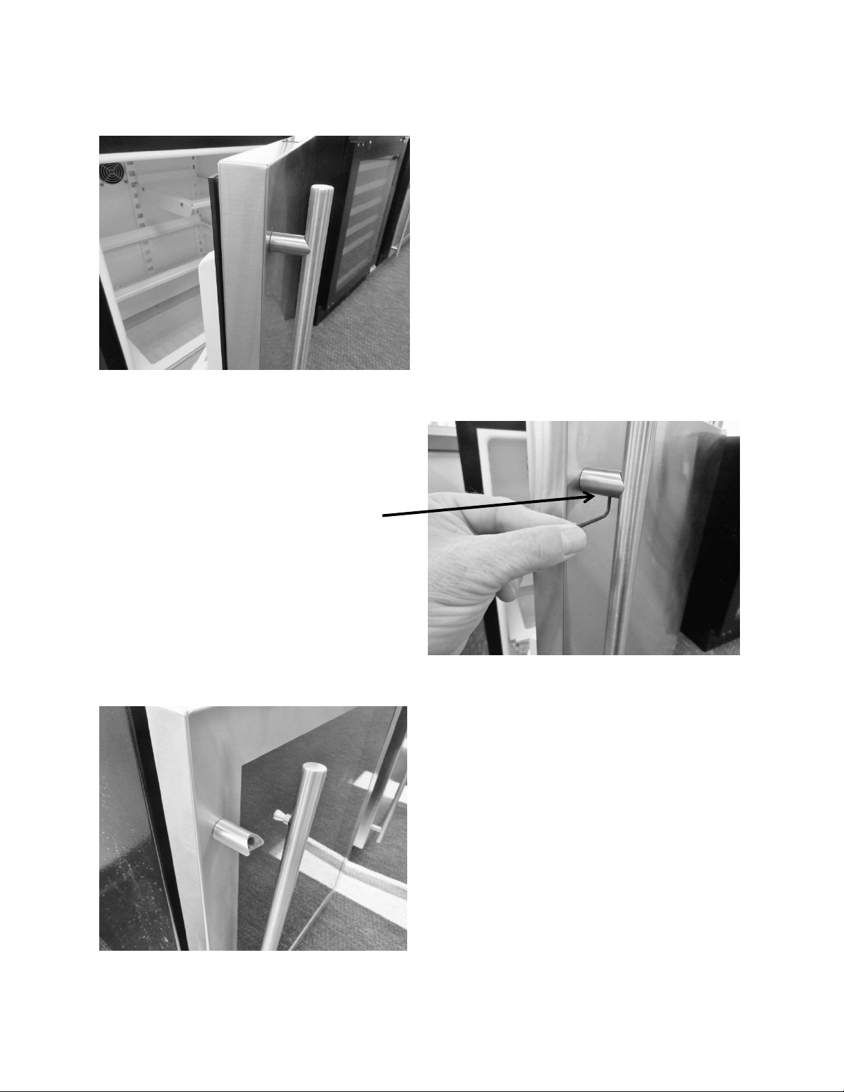
7.4: Doors / Drawers Handle Adjustment
3/32” hex head. Snug or
loosen the set screw firm. Do
not over tighten.
Both the door and drawer
handles are secured with a
3/32” hex set screw, on the
underside of each standoff.
Once loosened, the handle can
be pulled out of the standoff.
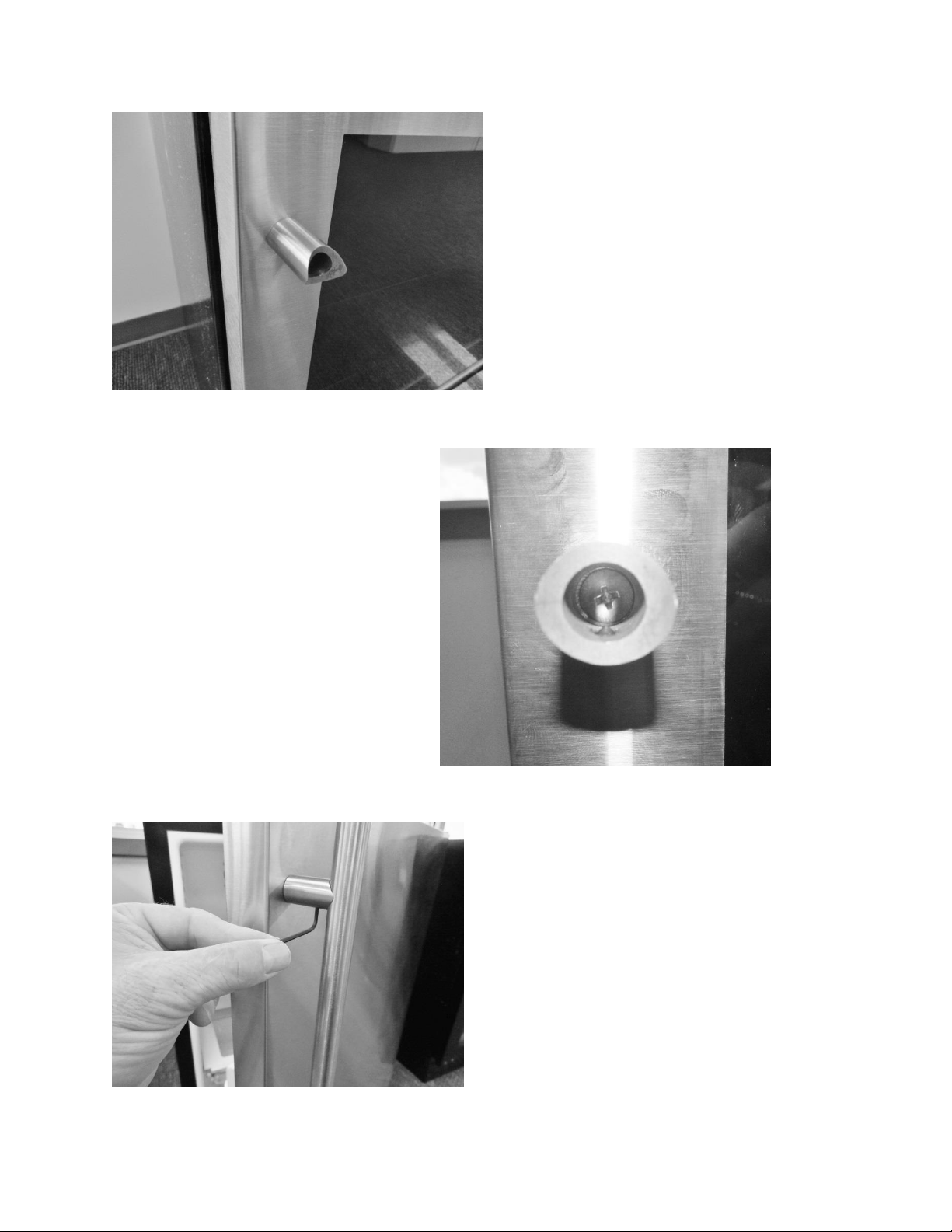
73
If the standoff is loose it can be
tightened with a Phillips screwdriver.
The head of the Phillips screw
inside the standoff. Turn the
screw clockwise to tighten.
Replace handle stud into the standoff,
turn clockwise with the Allen wrench,
and snug hex screw finger tight.
74
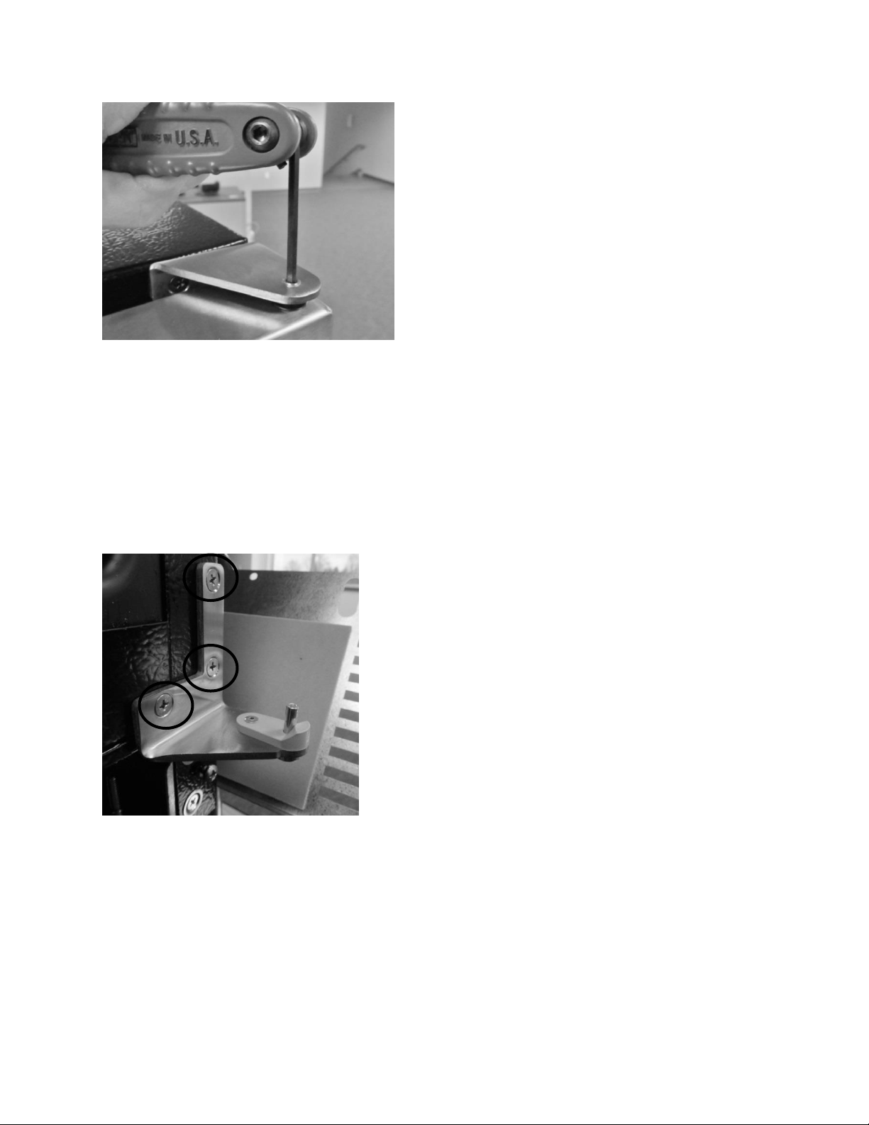
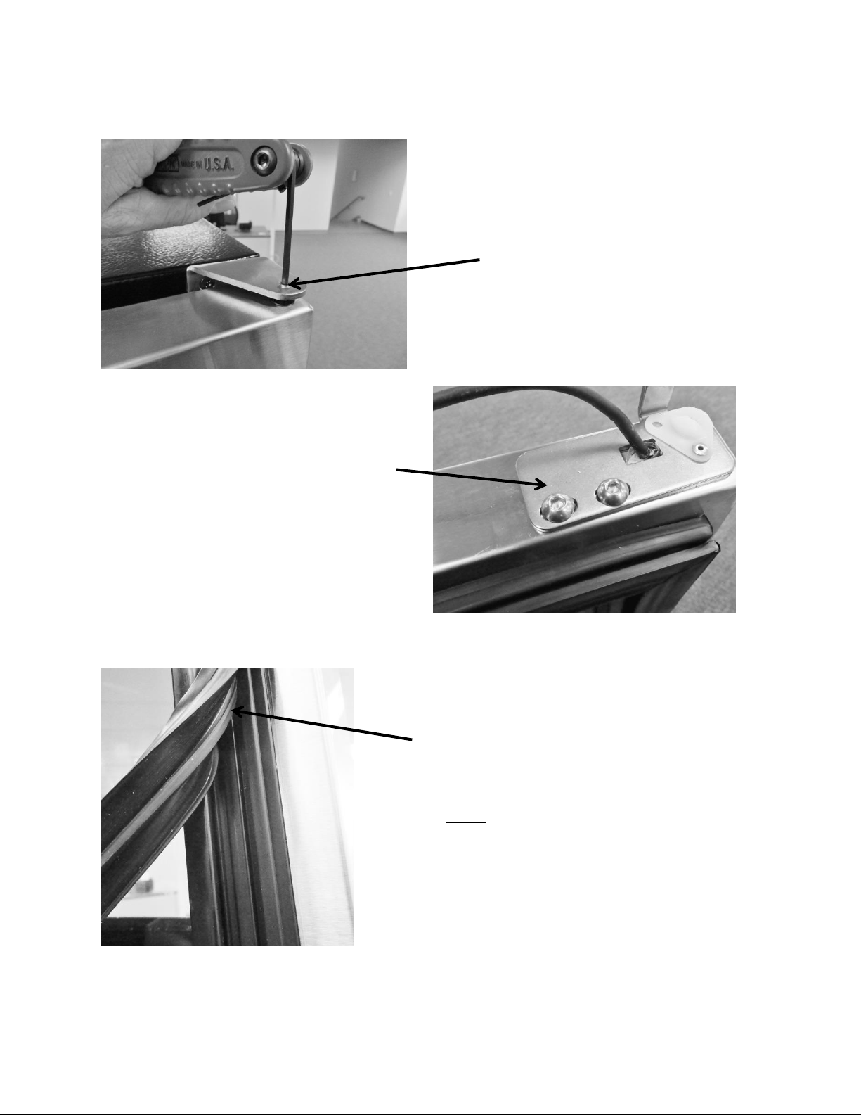
7.5: Door Alignment /Adjustment:
7.6: Gasket Adjust / Replace:
1/8” hex head. Turn the screw
counterclockwise to remove.
5/32” hex head. To adjust, loosen
both screws (counterclockwise) on
the bottom of the door. Slide the
bracket right, left or diagonally to
some degree to adjust door
alignment.
Press the gasket foot into the door channel to
reseal. Use your thumb to work the gasket in
place around the perimeter of the door.
NOTE: If adjustment, binding, rolling, or
pinching occurs, use a hair dryer to restore the
memory of the gasket to the cabinet flange.
75
7.7 Articulating Hinges:
Articulating hinges are standard on Marvel Professional and panel ready doors.
Professional and overlay door models cannot be installed free standing. Units with the
Articulating Hinge must be installed as built-in due to safety constraints.
Panel ready door shown
with articulating hinges.
Open Top Hinge:
Outside View.
NOTE: The top hinge is spring loaded
and has the capability to suddenly
close and severely pinching an
appendage.
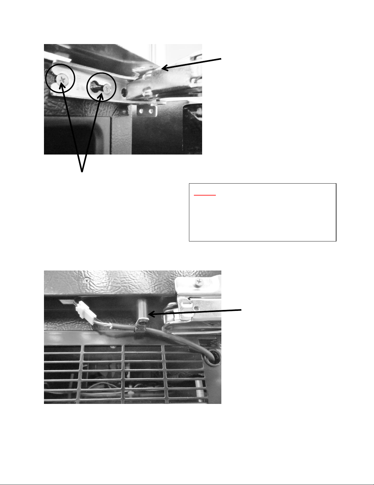
76
Open Top Hinge:
Inside View.
Loosen both screws, on top and
bottom hinges to remove door.
NOTE: Use caution with both the top
and bottom hinges as they have the
capability of severely pinching an
appendage.
The cable post is used only on
articulating hinge doors. Its purpose
is to keep the communication cable
from being pinched by the hinge. The
p-clamp, post and harness connector
must be detached from the door to
accommodate door removal.
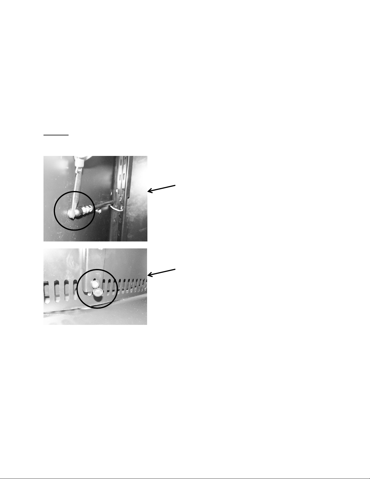
77
Section 8: Evaporator Compartment Access
To gain access to the evaporator compartment of the beverage center, wine cooler or
refrigerated drawers are very similar but slightly unique.
After drawers or shelving have been removed, the decorative plastic snap caps will have to be
removed to access screw removal for both the cantilever brackets, coil cover, and thermistor
shield.
NOTE: Refrigerated Drawers: See Section 7.3.1: Drawer Removal for additional
information.
8.1: Beverage Centers:
1. Remove all shelving
2. Remove both corner brackets and the center mounted bracket.
3. Remove decorative plastic snap caps.
4. The plastic cap located at the bottom of the center cantilever mounting rail is hinged on
one side; it is slightly larger than the remaining plastic decorative snap caps. Remove
screws around the perimeter of the coil cover.
5. Carefully remove the coil cover and disconnect the evaporator fan and thermistor wires
as needed.
Hinged screw cover. Location varies
on Beverage Center and Wine Cooler.
A knife or small putty knife is used to
pop each snap cap off the screw heads.
Place the blade on the rear base of the
cap and lightly pry upwards.
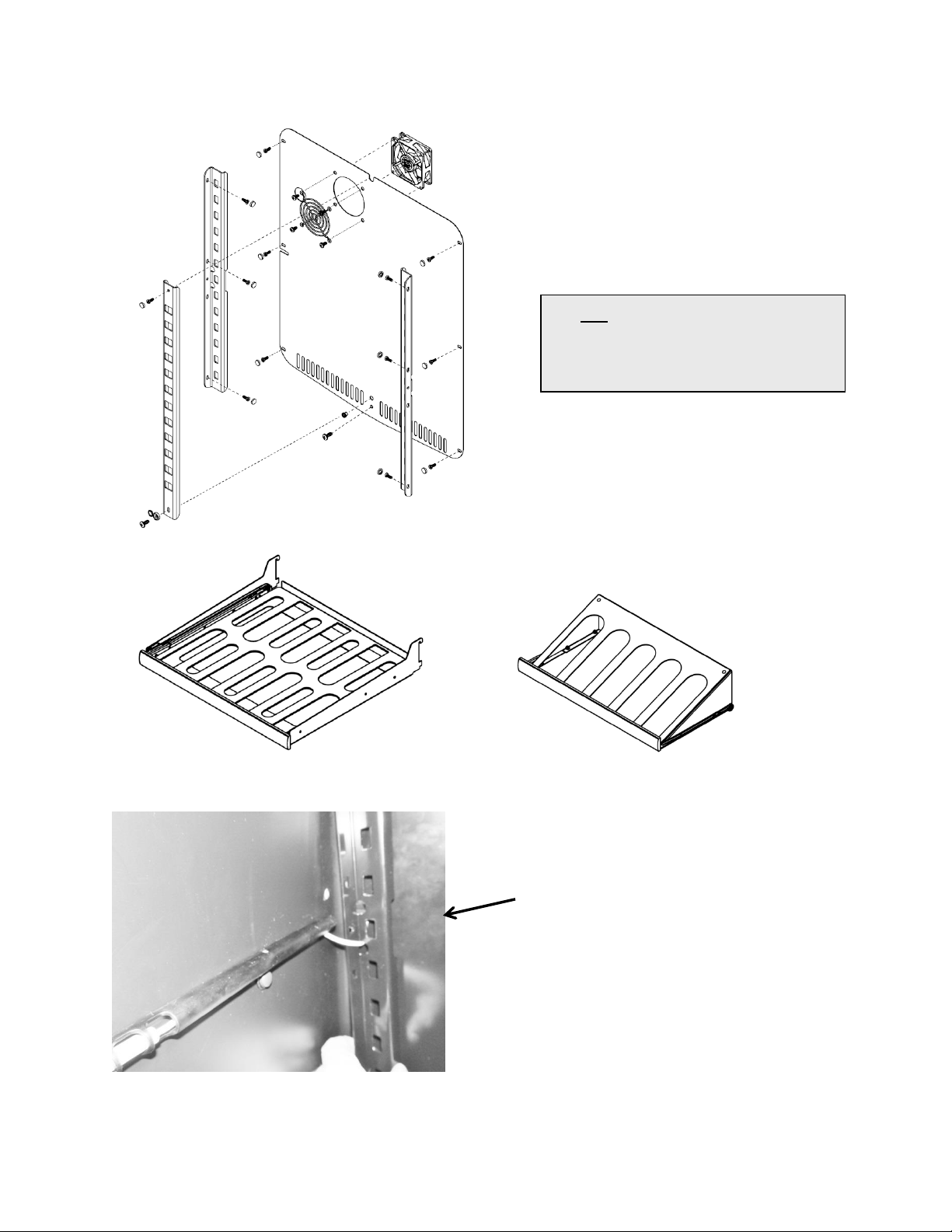
78
Beverage center only: The cabinet
thermistor will have to be removed from its
shield to allow it to pass through the
removed cantilever bracket.
Beverage Center: Exploded view of
interior and shelving
SEE Section 8.4 regarding the
evaporator cover drip edge
pertaining to all models
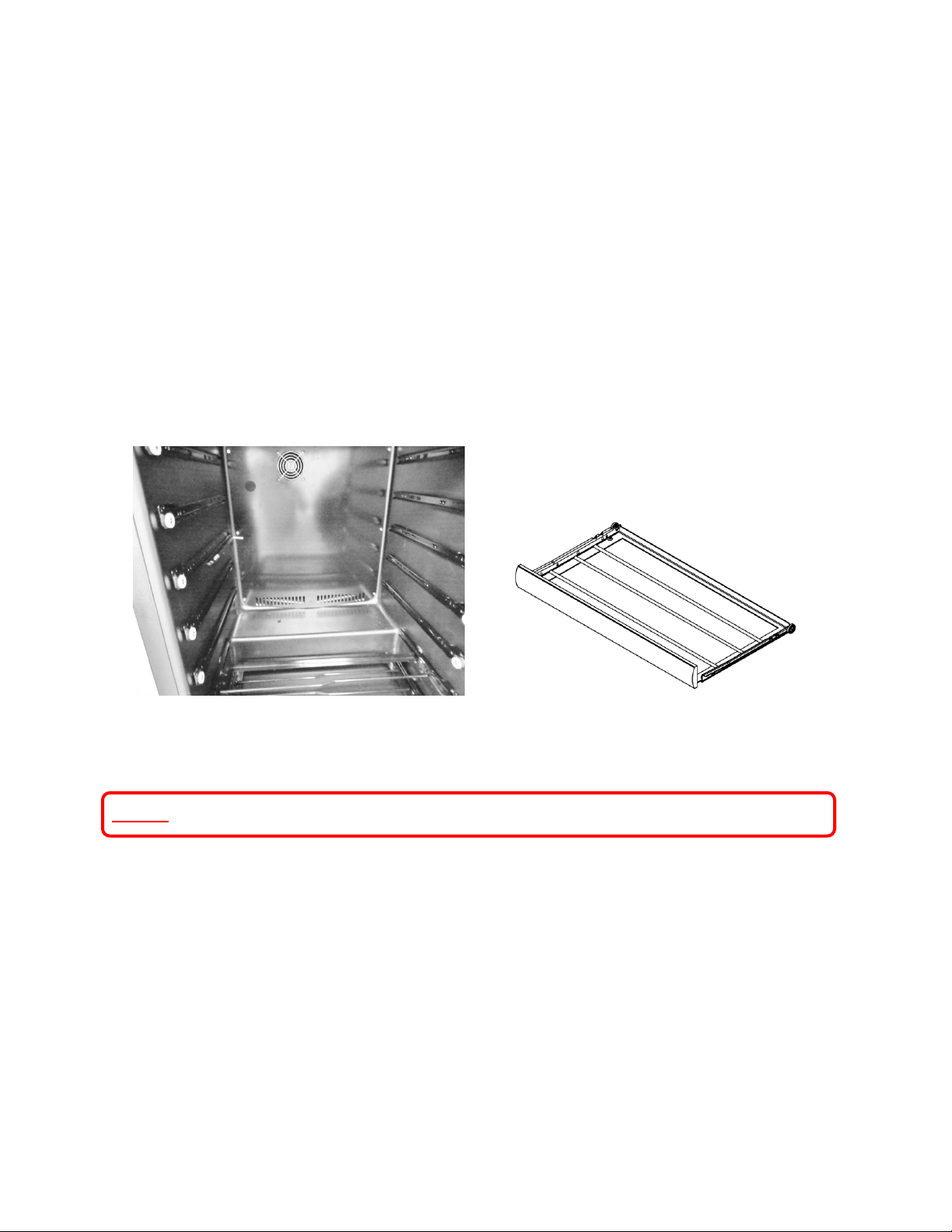
79
8.2: Wine Coolers:
Wine coolers have slide rail shelving with 7 pairs of slide rails on each side of the interior
cabinet.
1. Remove all shelving.
2. Remove decorative plastic snap caps.
a. The plastic cap located at the top center of the coil cover is hinged on one side; it
is slightly larger than the remaining plastic decorative snap caps.
3. Remove screws around the perimeter of the coil cover.
4. Carefully remove the coil cover and disconnect the evaporator fan and thermistor wires
as needed.
8.3: Refrigerated Drawers
NOTE: Refer to Section 19 for a Service Bulletin regarding a mullion heater kit.
To gain access of the evaporator and associated components located behind the coil cover.
1. Remove both top and bottom drawer (see section 7.4.1: Drawer Removal).
2. Disconnect the communication cable at the rear of the top drawer.
3. Remove the mullion bracket screws. (see section 15: SERVICE KITS for additional
information).
a. Remove the two top sheet metal screws securing the right hand mullion bracket
to the cabinet. Loosen the rear screw. The mullion bracket will stay with the
mullion when it is removed.
b. Remove the sheet metal screws on the top and bottom of the left hand mullion
bracket. The mullion bracket will stay attached to the cabinet.
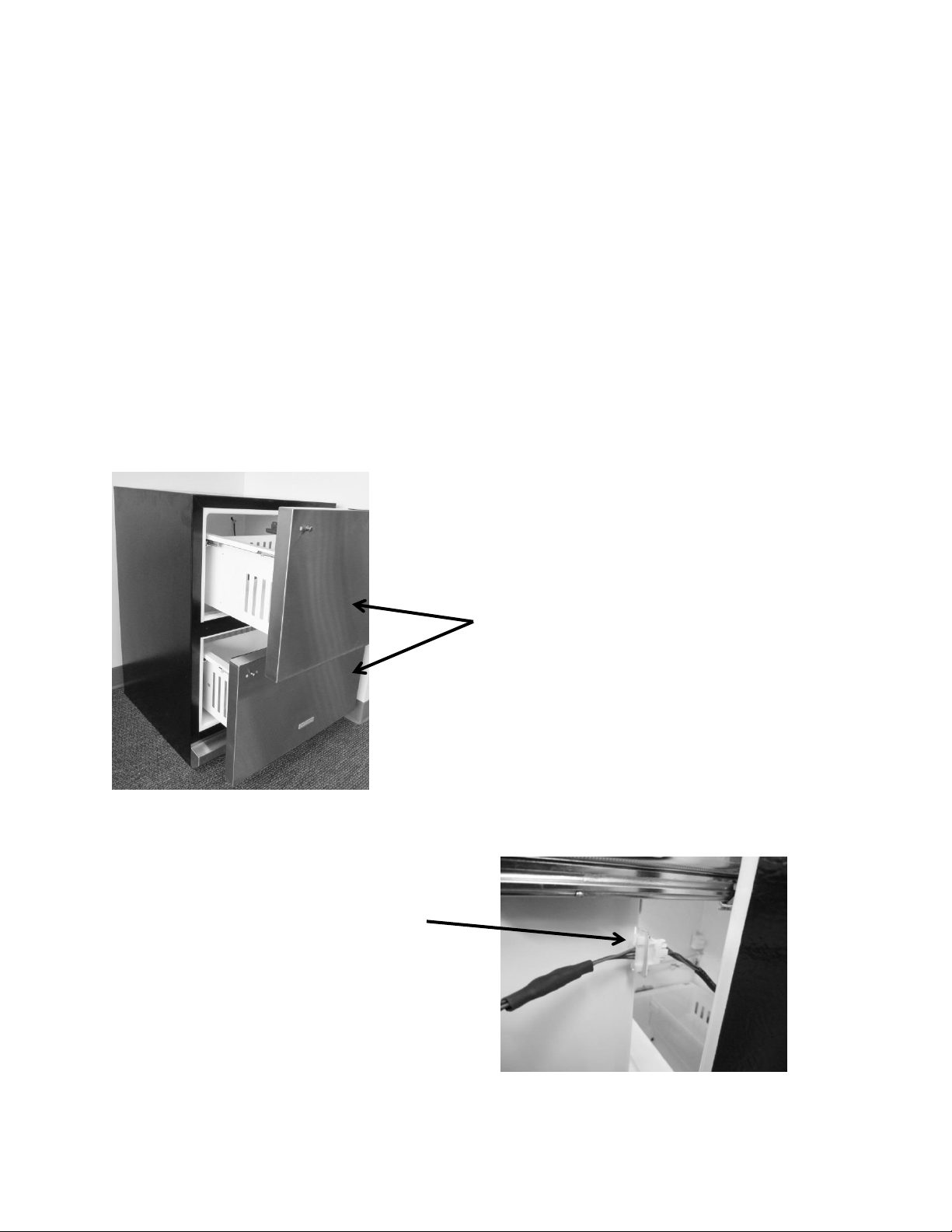
80
4. The mullion trim strip has a small lip that rests under the cabinet flange. The fascia
screw on each end of the mullion does not need to be removed.
5. To remove mullion:
a. Grasp the mullion with each hand.
b. Push mullion to the right to clear lip of flange on the left.
c. Rotate mullion forward to clear the mullion from brackets and liner.
d. Lift outward to remove.
6. Disconnect the LED harness on the right hand side of the mullion assembly.
7. Remove the decorative screw caps and screws that secure the coil cover.
8. Remove the P-clamp to the communication cable on the top right hand side of the coil
cover. This will allow enough slack to pull the coil cover outward.
9. Remove the coil cover by pulling outward on the right hand side to clear the rocker
switches on the left hand side of the cabinet.
10. Disconnect the fan harness; defrost thermistor, and cabinet thermistor as needed.
Disconnect the
communication before
drawers are removed.
Remove top and bottom
drawers.
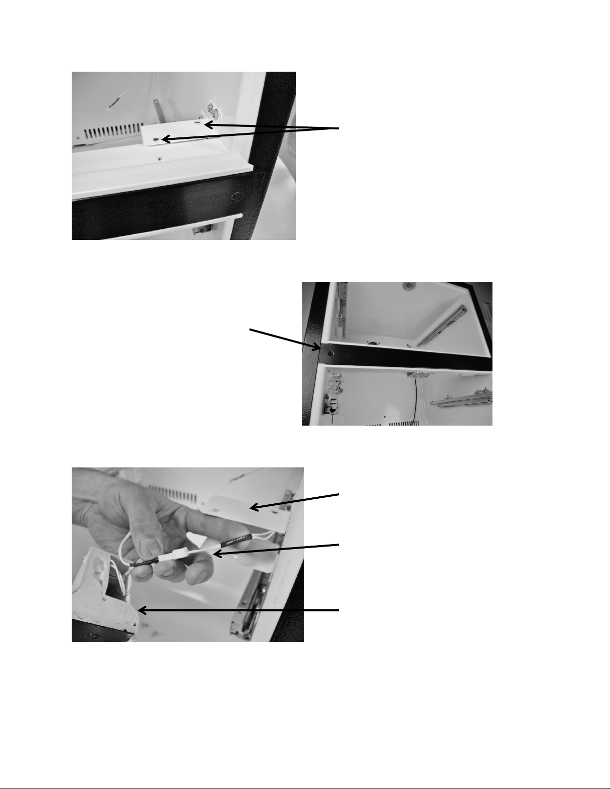
81
Remove two screws on the
top of the mullion bracket,
and one on the bottom.
Wiring harness for the mullion
LED. NOTE Disconnect.
Bottom mullion bracket.
Mullion fascia trim
does not have to be
removed.
Side View of Mullion Assembly.
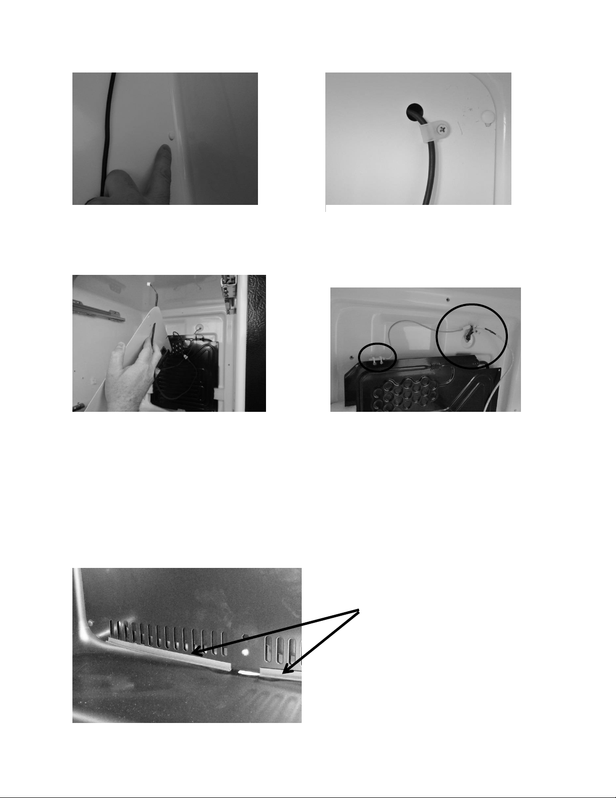
82
8.4: Evaporator Cover Drip Edge
The bottom of the evaporator cover has two plastic drip edges to deflect water/condensation
into the drain sump. These pieces need to remain on the cover for proper drainage.
Remove the decorative screw caps and
screws.
The coil cover can now be removed.
Remove P-clamp
The defrost thermistor is shown in photo (left-red).
Also shown are disconnects for the following: (1) fan
cable (2) communication cable and (3) defrost
thermistor.
1
2
3
Drip edge on bottom
of evaporator cover.
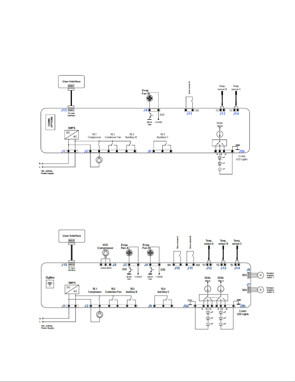
83
Section 9: Wiring Diagram
9.1 Block Diagram of Main Power Board
9.1.1 Single Zone
9.1.2 Dual Zone
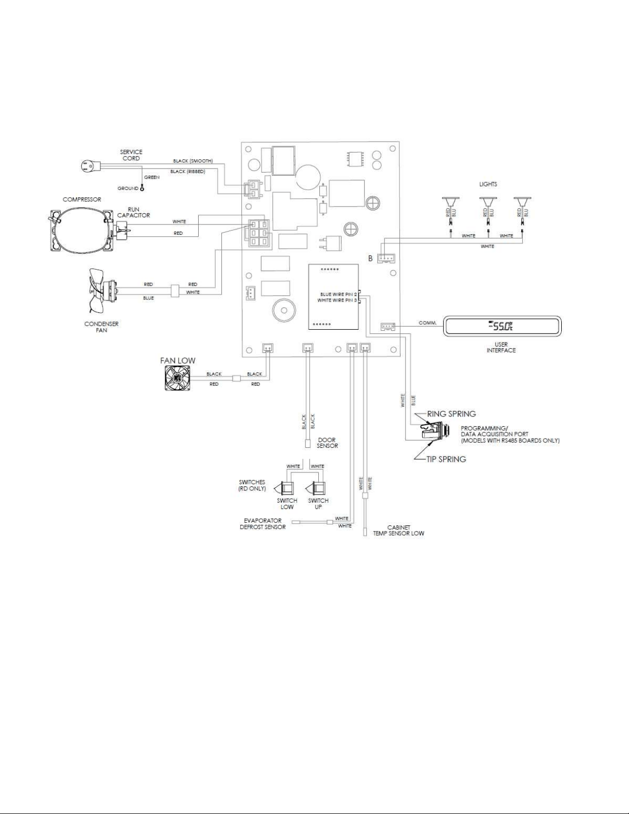
84
9.2 Schematic Diagram
9.2.1 Single Zone
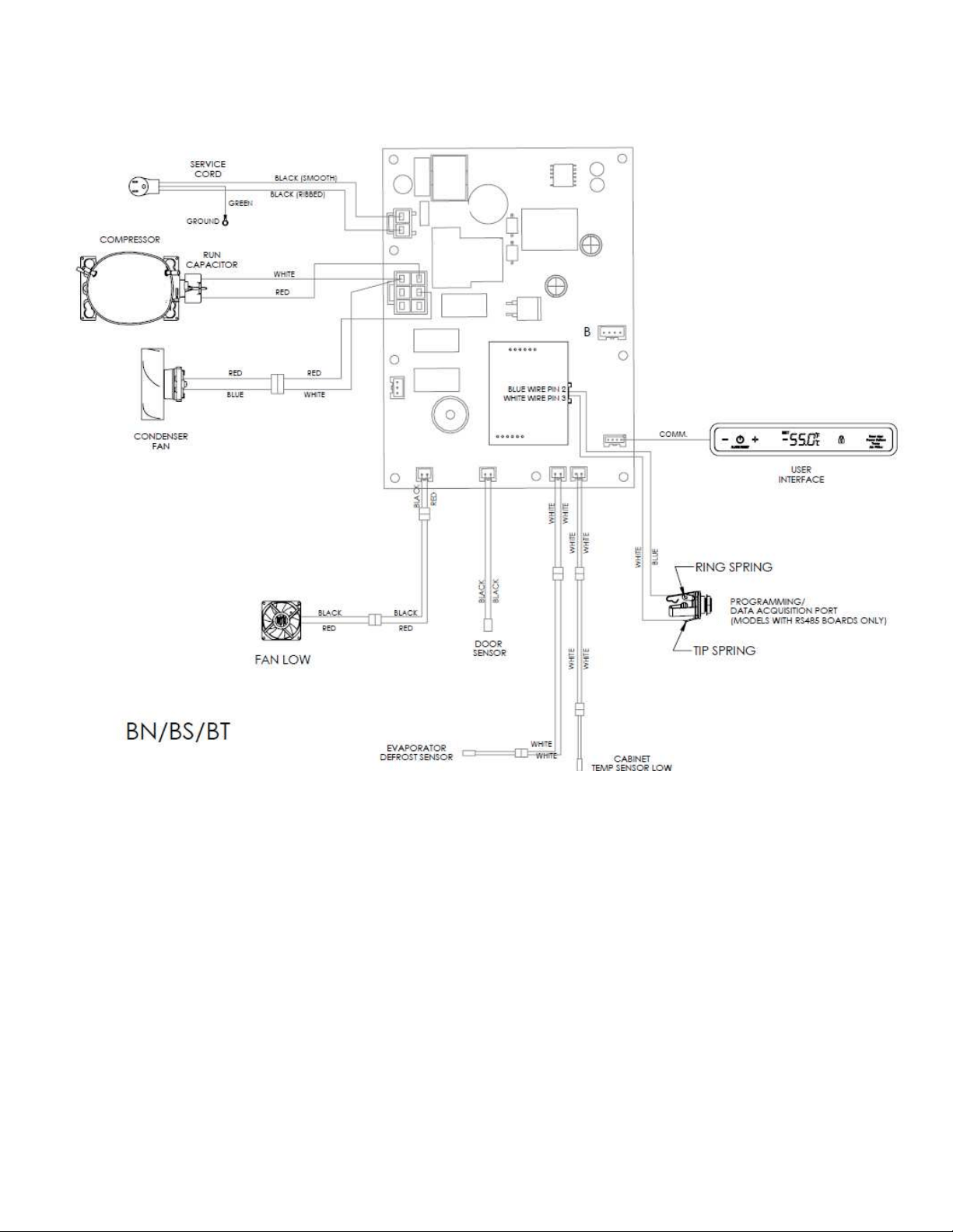
85
9.2.2 Single Zone – Beer Dispenser
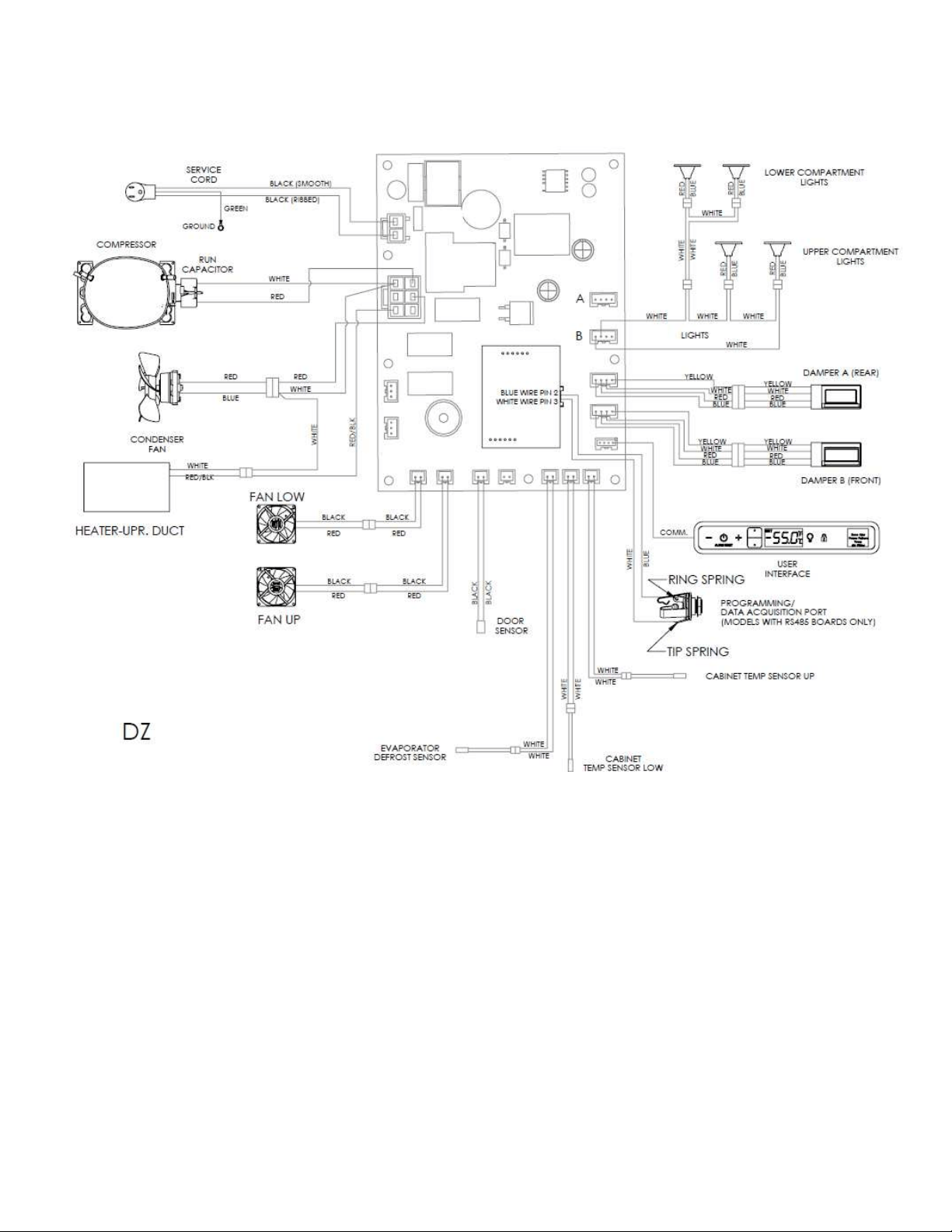
86
9.2.3 Dual Zone
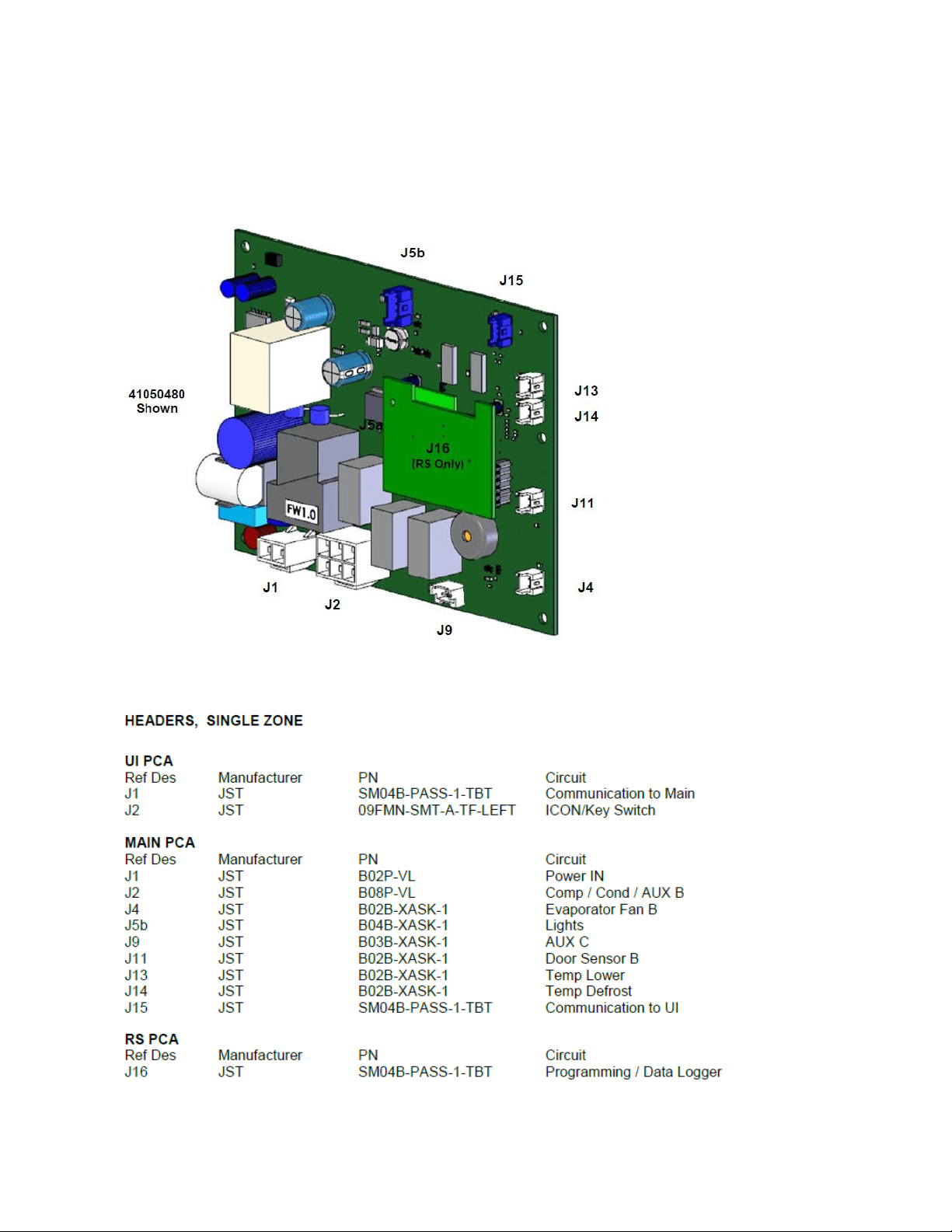
87
9.3 Main Power Board Identification
9.3.1 Single Zone
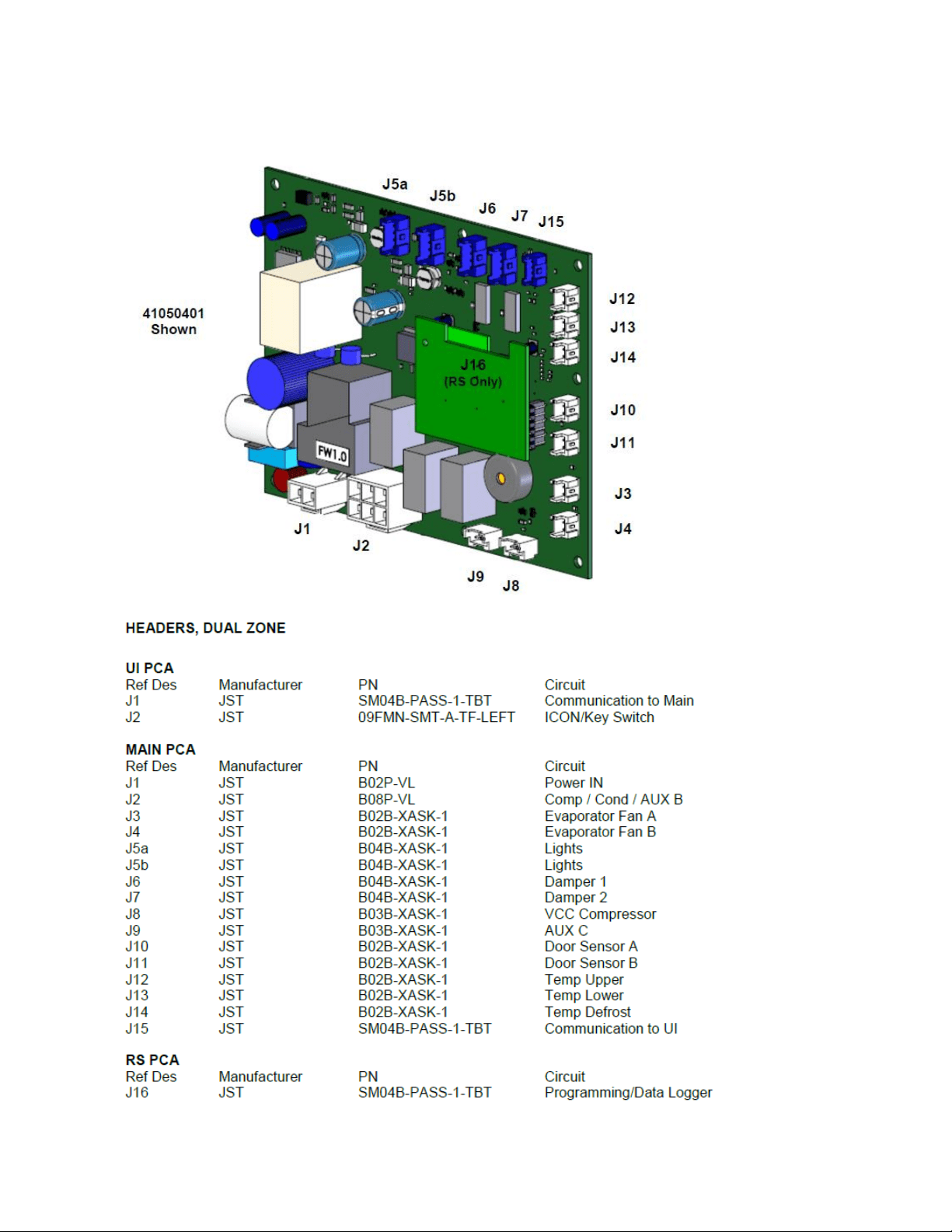
88
9.3.2 Dual Zone

89
SECTION 10: Power on Reset Mode
10.1: Auto Self-Test
Every “power on reset” (POR) will initiate an “auto self-test”. After each loss of power the
control will do a self-check once power is restored. This sequence will not be noticeable to the
owner.
During the auto self-test mode, the following conditions are evident:
Current temperature is displayed.
Lights work normally.
User can adjust the temperature set-points.
Lock function works normally.
ON/OFF key works normally.
o NOTE: If the unit is turned “OFF” during the auto-self test, the unit will not be
disabled until the conclusion of the test.
Green LED status indicator works normally.
In addition, during the auto self-test mode, the software version can be displayed by pressing
and holding the ON/OFF key while simultaneously pressing the LOCK key. During the auto self-
test the loads are sequentially enabled and then disabled.
10.2: Manual Auto Test Mode
An “auto test” can automatically be activated by the following key dance: Press and hold the
LOCK and + (plus) keys simultaneously. During the manual test mode, the software version is
automatically displayed until the test in complete.
Example: Display while in manual test mode: 4 (shows software version)
NOTE: The auto test sequence is identical in both POR and manual modes.
10.3: Control Types
Single zone
Dual zone
90
10.3.1 SINGLE ZONE:
AUTO TEST MODE
LOAD
ENABLED
Condenser (AUX A)
On for 15 seconds then OFF. Pause 2 seconds
Evaporator
On for 15 seconds then OFF. Pause 2 seconds
AUX C
On for 15 seconds then OFF. Pause 2 seconds
Comp & Cond Fan ONLY
On for 5 minutes then exit AUTO-TEST and RETURN to
NORMAL OPERATION.
NOTE: If there is a "Call for Cooling", upon return to
normal operation, the compressor and condenser fan
will remain enabled.
10.3.2 DUAL ZONE:
AUTO TEST MODE
LOAD
ENABLED
Condenser (AUX A)
On for 15 seconds then OFF. Pause 2 seconds
Evaporator Fan A
On for 15 seconds then OFF. Pause 2 seconds
Evaporator Fan B
On for 15 seconds then OFF. Pause 2 seconds
Damper A
Completes one CLOSE/OPEN/CLOSE cycle then OFF. Pause 2 seconds
Damper B
Completes one CLOSE/OPEN/CLOSE cycle then OFF. Pause 2 seconds
AUX B
On for 15 seconds then OFF. Pause 2 seconds
AUX C
On for 15 seconds then OFF. Pause 2 seconds
Comp & Cond Fan ONLY
On for 5 minutes then exit AUTO-TEST and RETURN to NORMAL OPERATION.
NOTE: If there is a "Call for Cooling", upon return to normal operation, the
compressor and condenser fan will remain enabled.
NOTE
No two loads can be on at the same time. The previous load must be
completely “Off” before the next load is enabled.
91
SECTION 11: Quick Reference Troubleshooting Guide
COMPLAINT
CONDITION
CAUSE
ERROR CODES
EL
Compartment Thermistor: Open or
shorted (no audible tone).
Broken / Worn / Shorted thermistor: Check
resistance (Ohm) and replace.
Ed
Defrost Thermistor: Open or shorted
(no audible tone).
Broken / Worn / Shorted thermistor: Check
resistance (Ohm) and replace.
EL / Ed
Multiple Thermistor Failures: Open or
shorted (no audible tone).
Broken / Worn / Shorted thermistor: Check
resistance (Ohm) and replace.
ALARMS
Door Ajar
“Door Ajar” will flash on Display (with
audible tone.)
Appliance door has been open or ajar for a
period of 5 + minutes. Close door or press
ON/OFF key to reset.
Power Failure
“Power Failure” will flash on Display (no
audible tone).
Internal / External related supply power
disturbance. Press ON/OFF key to reset.
Temperature
Compartment is 10 + degrees higher /
lower than Set Point for longer than 1
hour.
Electrical / Mechanical / Installation related.
Alarm will sound every 60 seconds>Press
ON/OFF key to reset. Alarm will continue
until cause is corrected.
MISC
Unit does not operate.
Lack of power to the unit or display.
Check power to the appliance and power at
the main power board.
Display Blank
Lack of power/ Display off/ Faulty
display.
Attempt to turn on display/ Check for
incoming power to appliance and display.
Compartment temperature to
cold.
Faulty thermistor/ Compartment Fan
Failure / System failure.
Check resistance (Ohm) and replace
compartment thermistor.
Compartment temperature to
warm.
Product not Stabilized/ Faulty
Thermistor/ Electrical or Mechanical
failure.
Stabilize 24 hours/ Check resistance (Ohm)
and replace thermistor/ Check fan / Look for
leak or restriction.
Compressor does not run.
No Power to compressor/ Faulty
compressor or overload -relay/ Faulty
main power board.
Bad main power board/Check compressor
windings/Check overload and relay.
Compressor runs but doesn't
cool.
Mechanical failure
System Leak
Compressor hot/ tripping.
Faulty compressor windings, overload,
relay.
Shorted or grounded compressor windings,
overload, and relay.
Excessive frost/ice build- up on
evaporator.
Excessive door/drawer openings or
Mechanical failure.
Customer education/ Restriction/
Overcharge.
Uneven frost pattern on
evaporator.
Mechanical failure
System leak/ Restriction
Condensate on face of
gaskets/mullion/doors.
High Humidity
Check repair / replace gaskets, Adjust
doors/drawers.
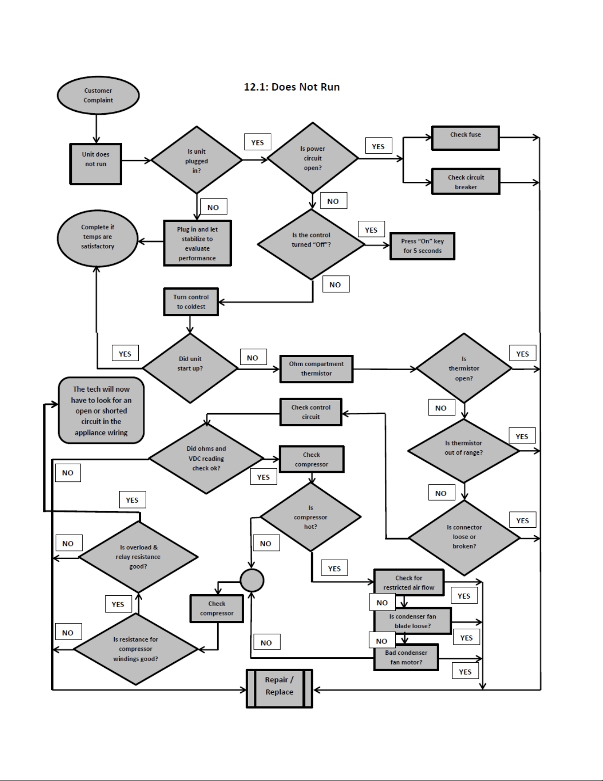
92
Section 12: Flow Chart Diagnostics
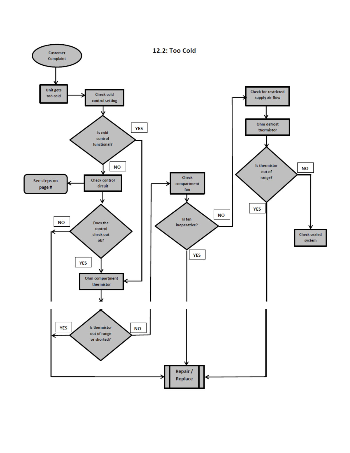
93
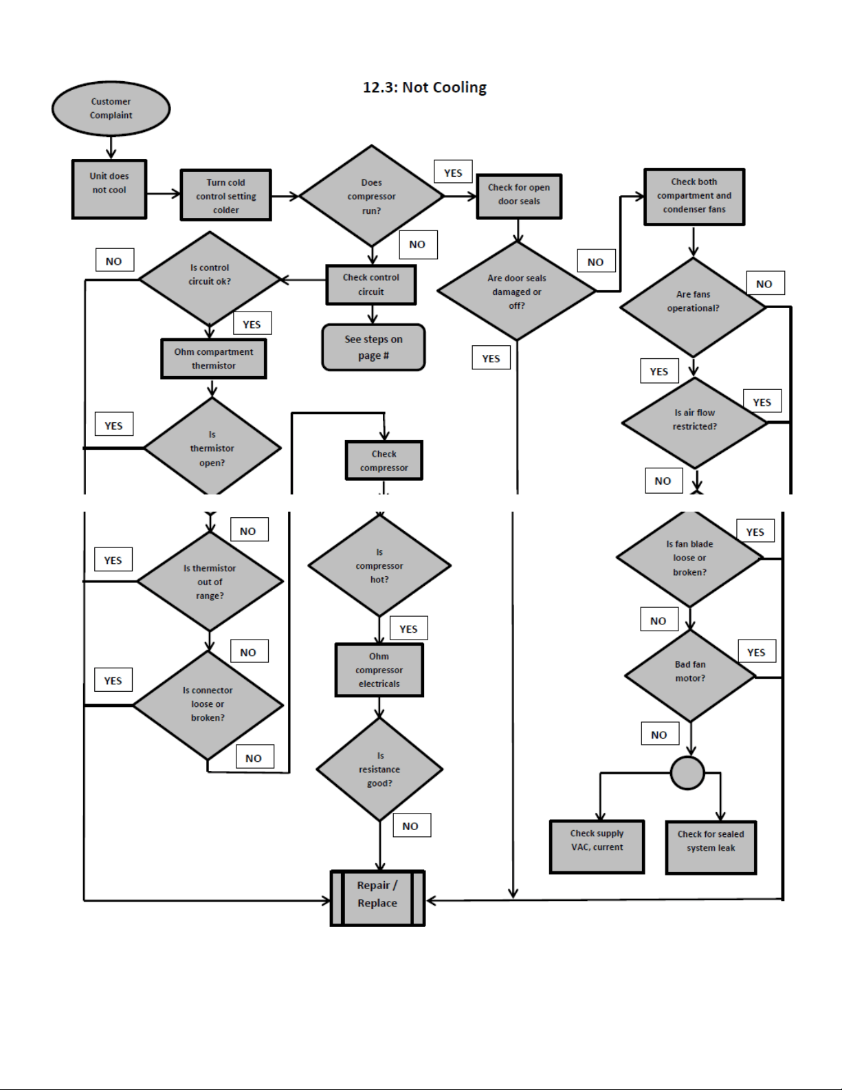
94
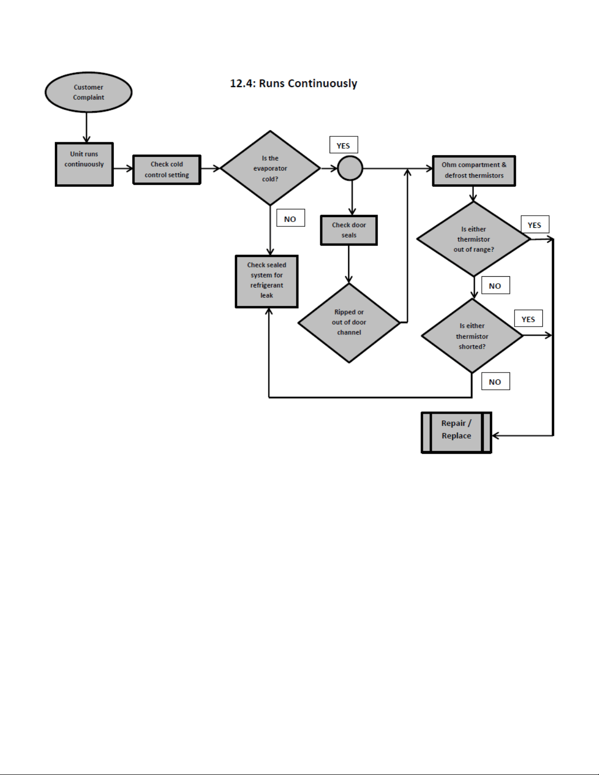
95
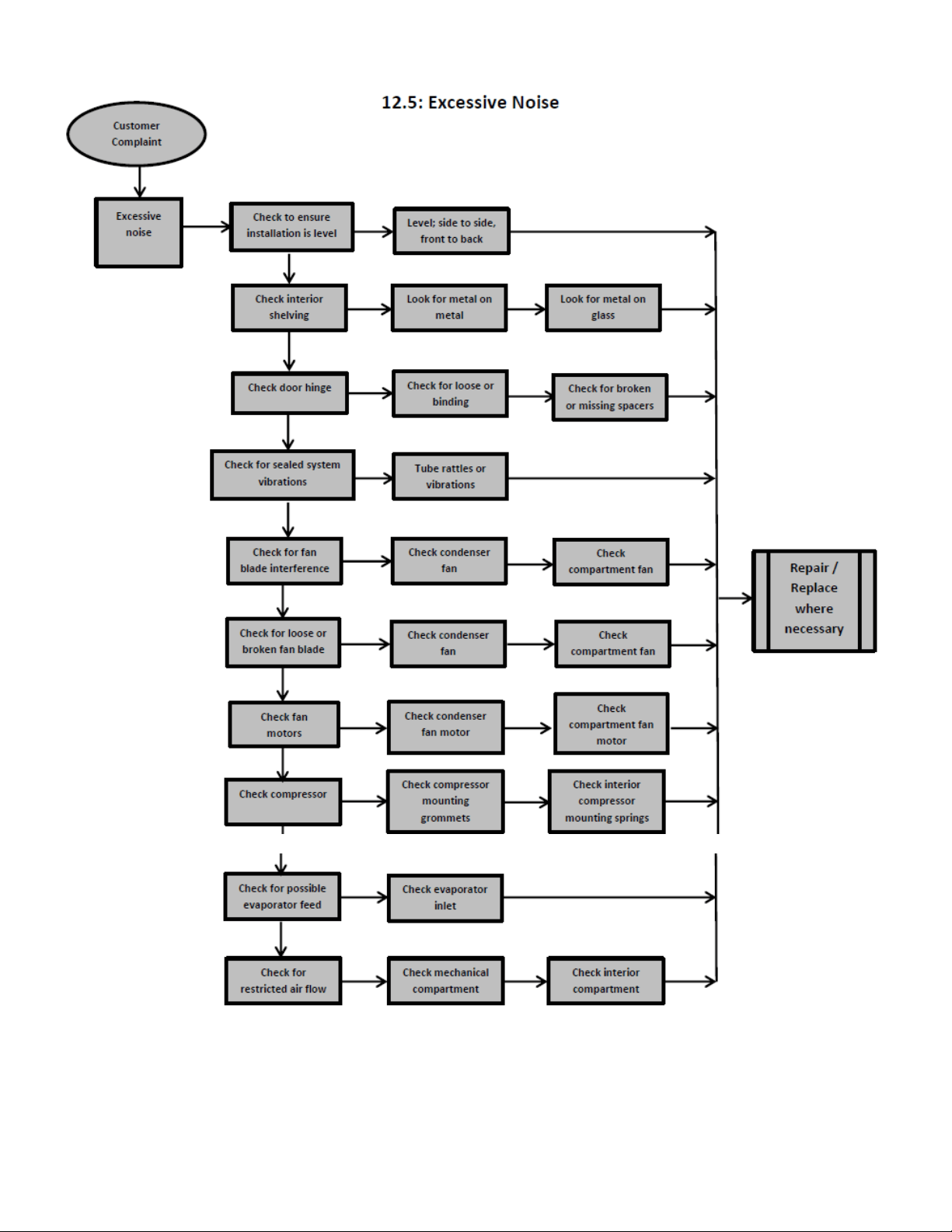
96
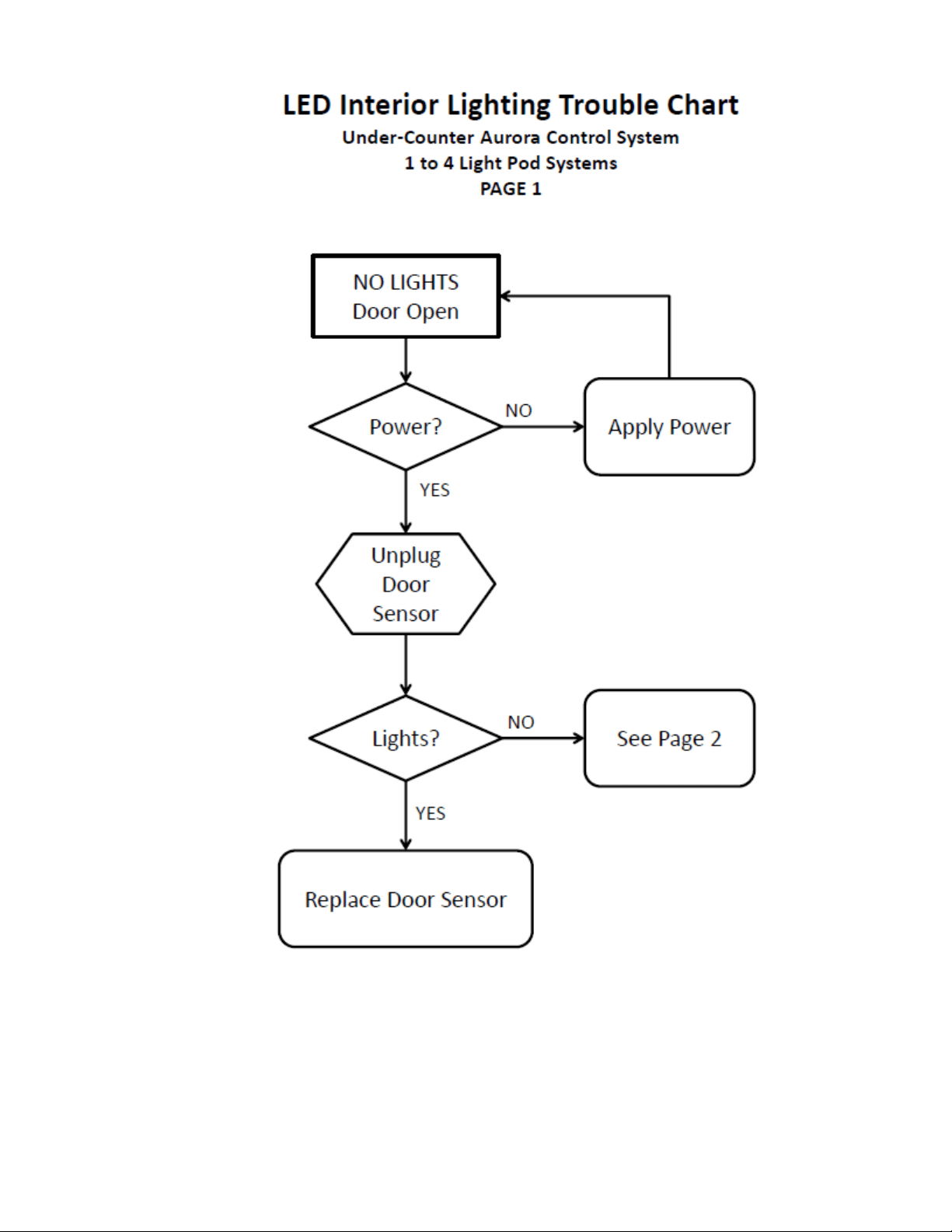
97
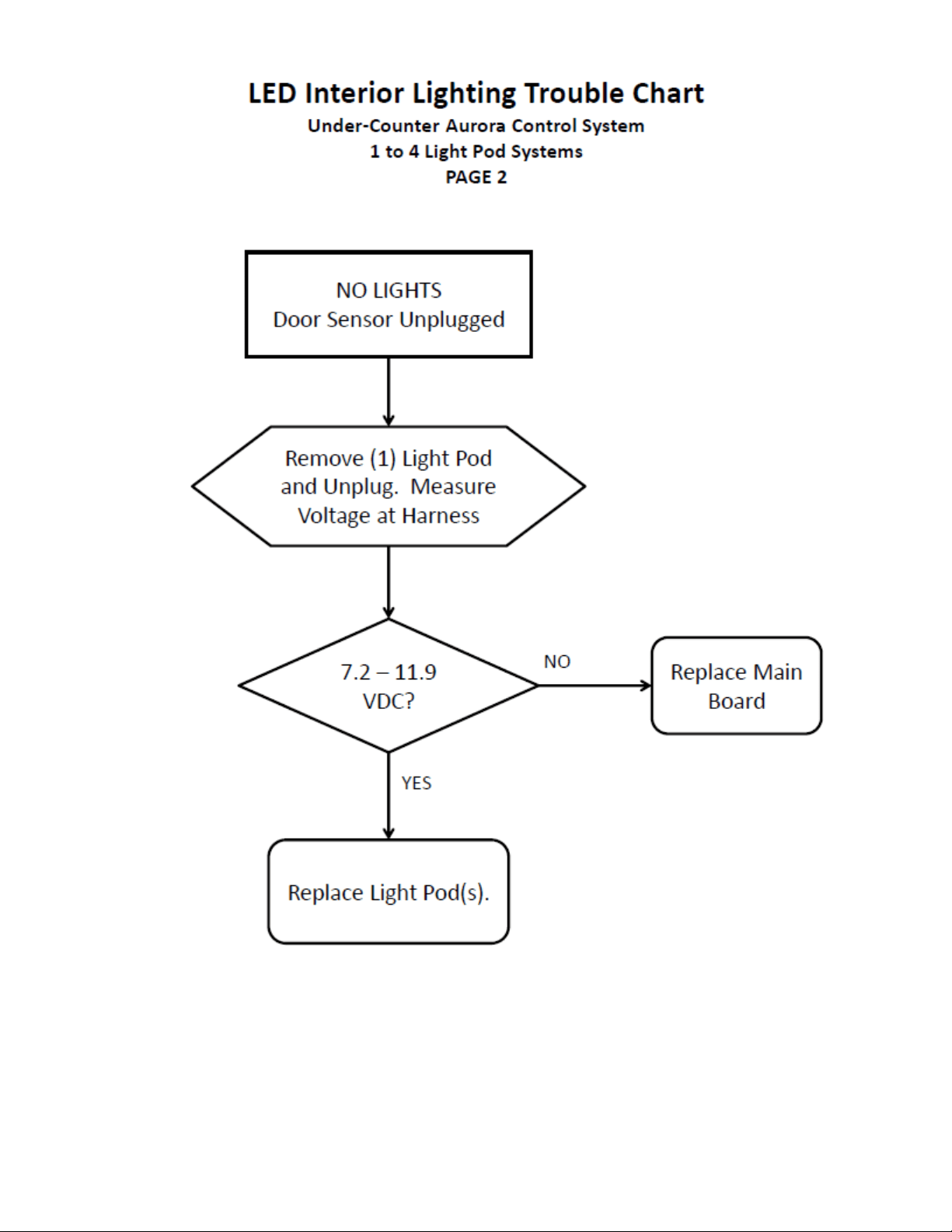
98
99
Section 13: Service Data
13.1: PROGRAM PORT
Programming or re-programming is accomplished through a port located behind the toe grill.
Model specific, factory default settings cannot be modified or adjusted in the field. However, if
a new software or firmware version becomes available it is possible to upload the latest version
through this program port.
13.1.1: SERVICE DATA RETRIEVAL
Historical data can be downloaded in a file format compatible with Microsoft® Excel through a
PC USB port. Historical data will record a running report of the past 72 hours.
The service data report will be formatted in a time sequence as follows:
EXAMPLE:
0 = Current Time
-1 = 1 Hour Ago
-2 = 2 Hours Ago
-3 = 3 Hours Ago
-72 = 72 Hours Ago
Data available per report is
Cabinet temperature set point
Temperature sensor A (average)
Temperature sensor B (average)
Temperature sensor C (average)
Number of door A Detections
Number of door B Detections
Number of compressor “ON” Cycles
Number of defrosts
Number of alarms
The data cable and application will be available upon request from AGA Marvel customer
service (1-800-223-3900).
The retrieved data format will apply to a standard excel spreadsheet.
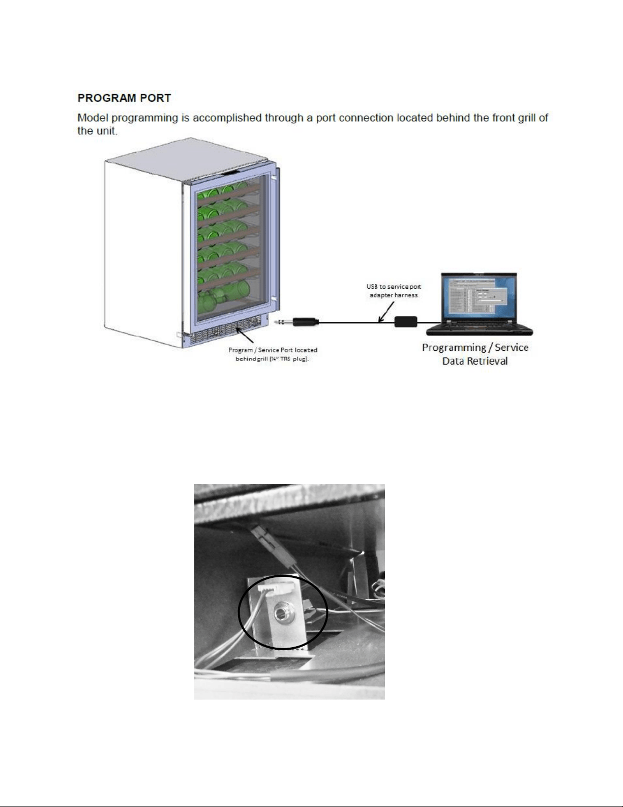
100
13.1.2: Service Data Port Location
The service data cord will connect to the technician’s computer with a USB connection on one
end and then into the appliance data port by means of a jack plug.
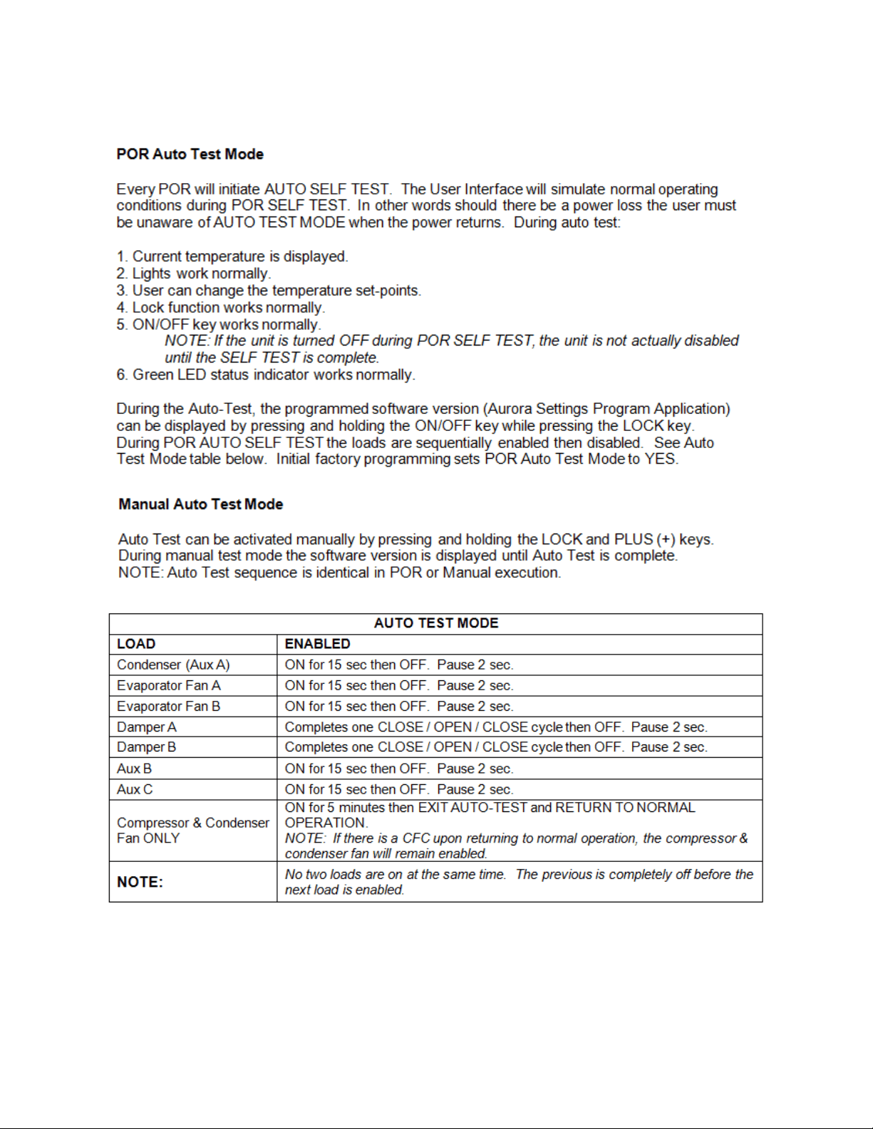
101
13.1.3: Onboard Diagnostics
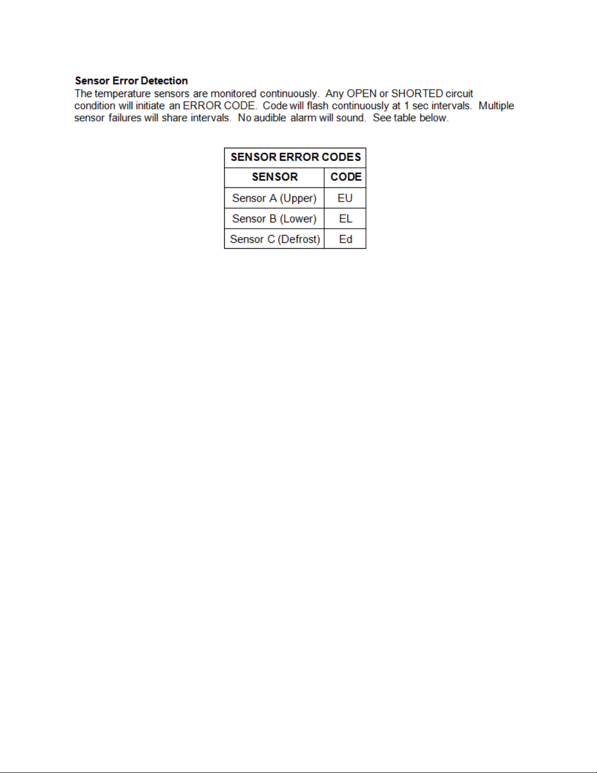
102
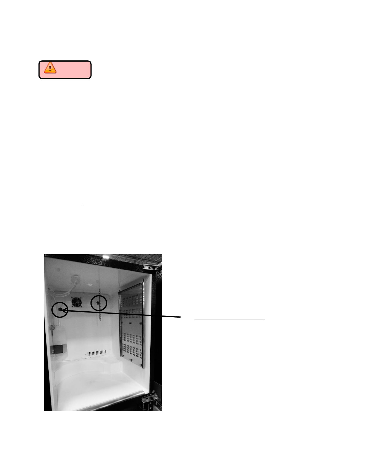
103
Section 14: Beer Dispenser
Caution Prior to preceding with any of the following steps the main
power to the appliance and/or the power cord should be disconnected from the
power supply. Failure to do so could result in severe shock.
14.1: Interior mechanical / electrical components
The components are accessible as described in previous sections.
Remove all interior beer dispenser accessories: keg, co2 tank, regulators, and lines.
Remove shelving in lieu of keg equipment (depending on customers’ installation).
Remove plastic screw caps from freezer cover.
Remove Phillips screws.
Pull freezer cover away from back wall enough to disconnect the evaporator fan
harness.
The interior fan, both thermistors, and the evaporator plate is now exposed.
NOTE: The evaporator fan for the beer dispenser has reversed air flow compared to the
other Marvel models. The fan application is draw through. Interior cabinet air is pulled
through the fan orifice, across the evaporator plate, and outwards from the louvers on
the evaporator cover.
Note the two hole locations on the
photo to the left.
The hole on the left hand side is used
for factory test purposes only; this is
sealed with a white plastic cover.
The hole on the right hand side is
used as a port to accommodate an
optional field install kit for an
externally mounted CO2 tank. This
will also be sealed with a white plastic
cover.
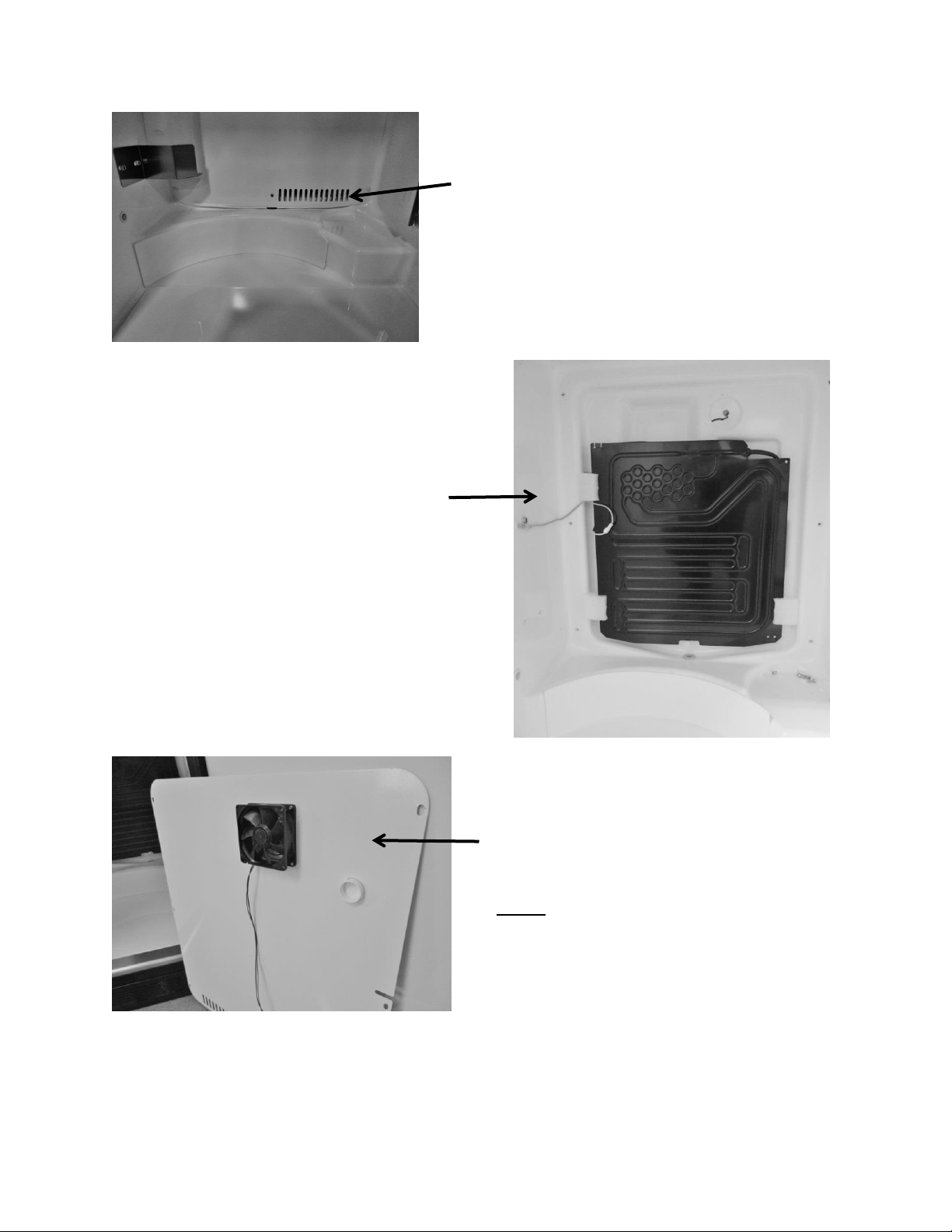
104
Evaporator and thermistor
location behind evaporator cover.
Evaporator fan is secured to the
rear of the evaporator cover.
Supply air louvers on the
evaporator cover.
NOTE: Newer models made after
20150824xxxH also have a rear fan guard.
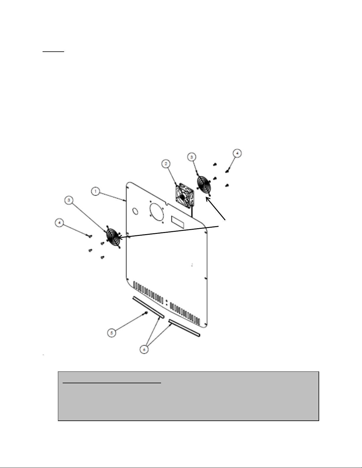
105
NOTE: As of mid-August 2015, a rear fan guard was added to the fan assemblies on beverage
dispenser models. The fan guard is to eliminate the possibility of wires getting caught in the fan
blade from behind the coil cover.
The approximate serial number range is 20150824xxxH. This is an approximate date and some
variation may be seen in the field.
The following exploded view shows the assembly drawing of the coil cover components along
with both the front and rear fan guards.
Air Flow on Beer Dispensers: The evaporator fan is a draw through design.
Specification label will face towards the evaporator when installed
correctly. The fan blades will rotate in a counter-clockwise direction as you
face the hub.
This exploded view drawing shows
the front and rear fan guard. As
mentioned on the previous page, the
additional rear fan guard was added
to beverage dispensers to prevent
wire interference.
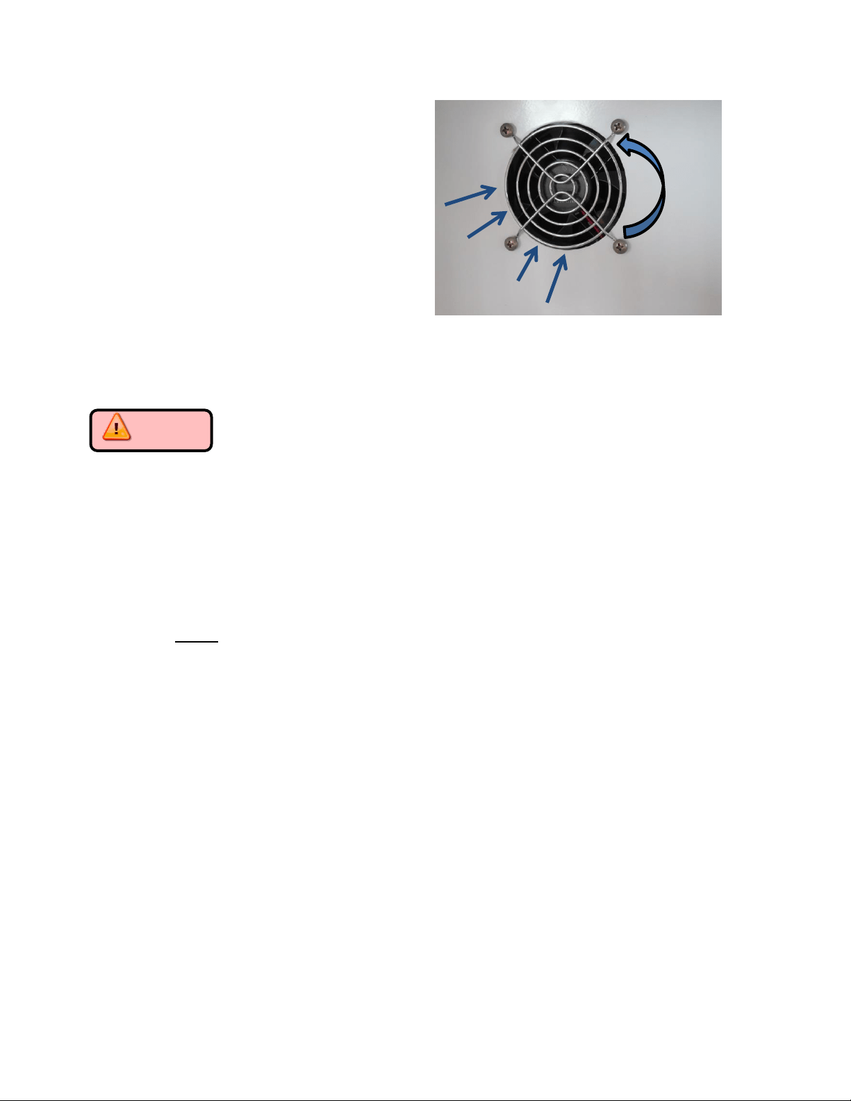
106
14.2: Main Control Board Access
Caution Disconnect the main power supply to the appliance. Failure to do
so could result in severe shock.
1. The main power board can be accessed as follows:
Remove the front toe grill.
Locate the control housing assembly. See below.
Use a Phillips screwdriver and remove the two screws securing the control housing
assembly to the machine compartment base.
The control housing can now be slid outward away from the machine compartment.
NOTE: the rear of the control housing assembly is slotted to lock into a mounting
tab on the cabinet base. When re-installing; care must be taken to ensure that the
board is locked into place without pinching any wire harness.
Secure the control housing using the Phillips screws previously removed.
Replace the toe grill and secure.
2. The user interface functions the same as the other Aurora control systems.
See Sections 6 and 9 for reference.
3. Operating functions and navigation for the user interface can be reviewed in section 5.
Remove the four screws from the front of
the coil cover to remove either fan.
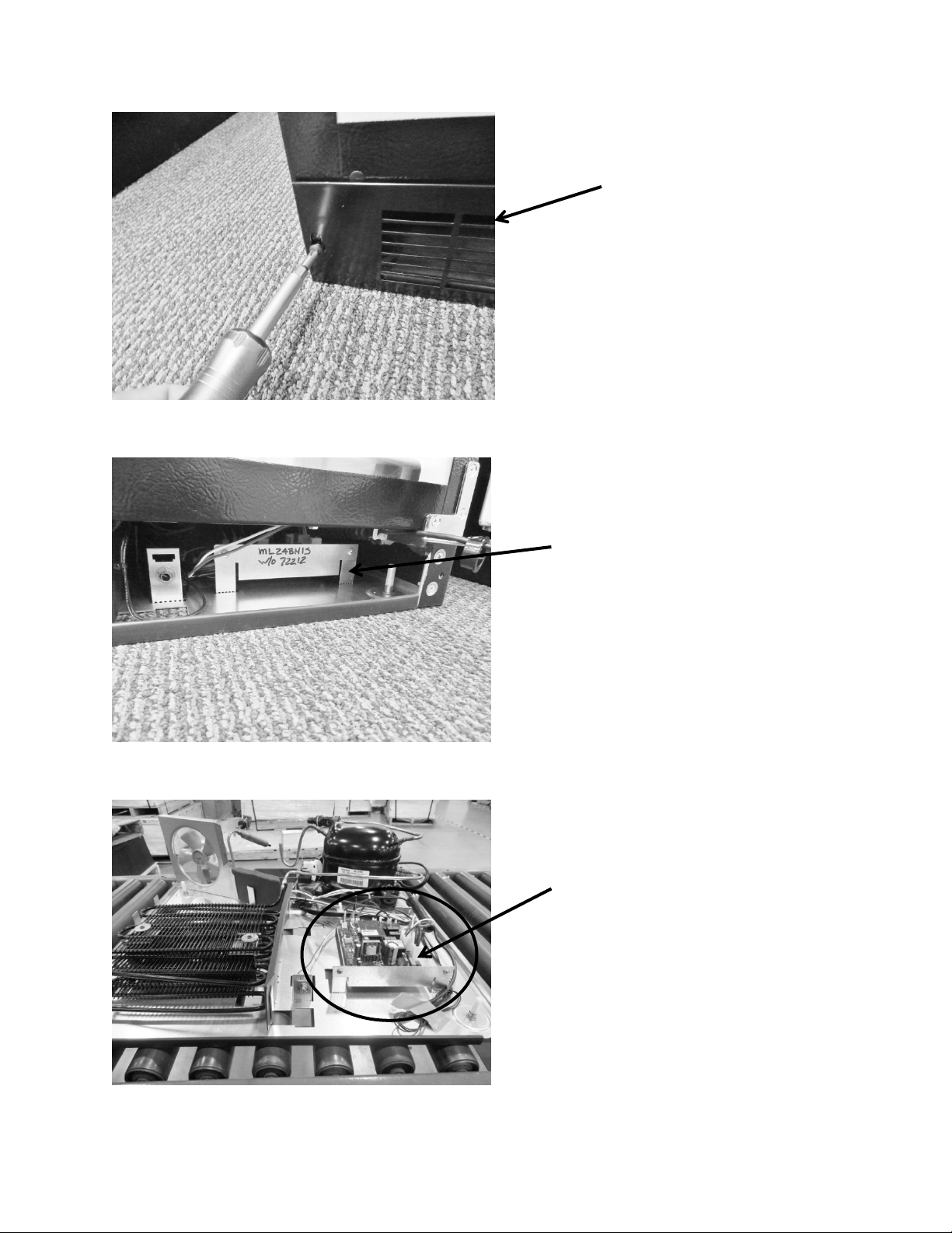
107
To access the main
power board; remove
the toe grill.
FOR REFERENCE: The bottom base assembly is
shown to help identify component locations.
The control housing assembly is circled in red.
Control housing assembly: The main power
board is located in the front, right hand
side, behind grill (beer dispensers only).
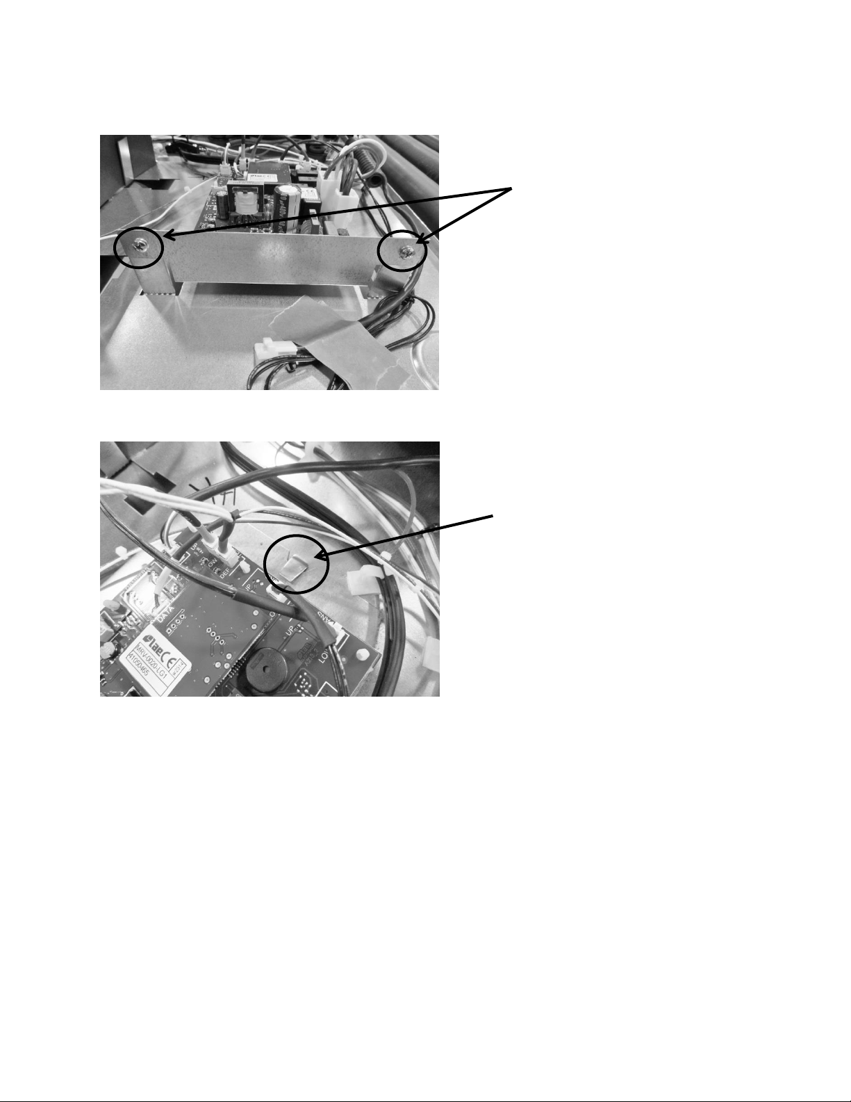
108
14.3: Machine Compartment
Access to the machine compartment is standard on all Marvel models.
The layout of the mechanical compartment is reconfigured due to the space constraints
of maintaining the volume of the refrigerated space.
See the Note below regarding the condenser fan.
14.3.1 Refrigeration and Mechanical
The basic refrigeration and mechanical operation and assembly are not unlike that
discussed earlier in this manual. This information can be reviewed in chapters 3 and 4.
Note the two Phillips screws
securing the front of control
housing assembly.
Note the slot and tab positioning.
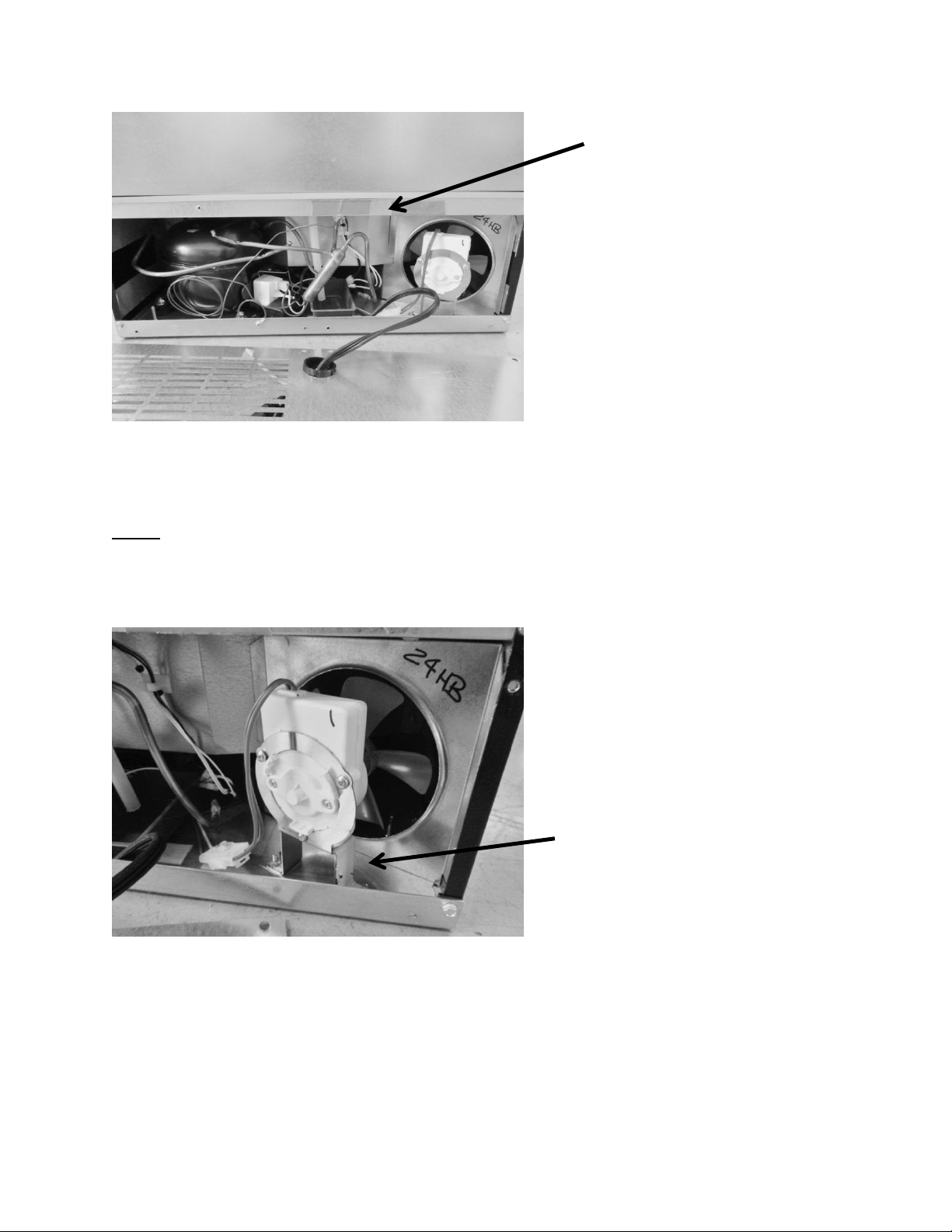
109
NOTE: The condenser fan blade used for the beer dispenser is 3/4” smaller in diameter then
the blade used on the remaining Aurora control models.
The condenser motor can be replaced by
releasing the disconnect plug and
removing the nuts holding the mounting
bracket to the base assembly.
View of the machine compartment
components with back panel removed.
NOTE the location of the compressor,
drain, condenser fan, and filter drier.
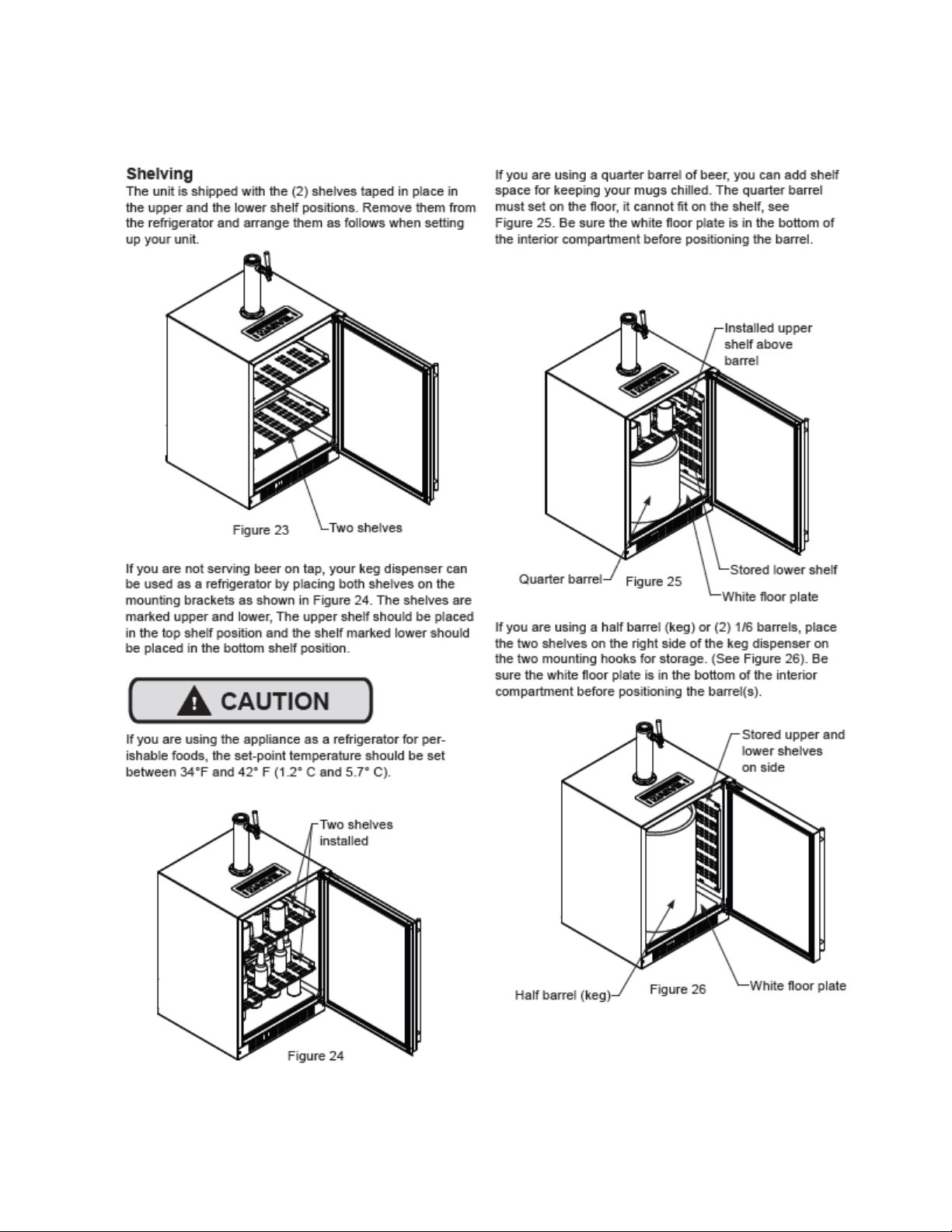
110
14.4: Excerpt from Owners / Maintenance Instruction Guide 41013400-Rev D
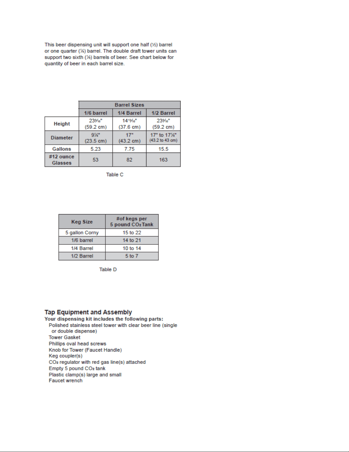
111
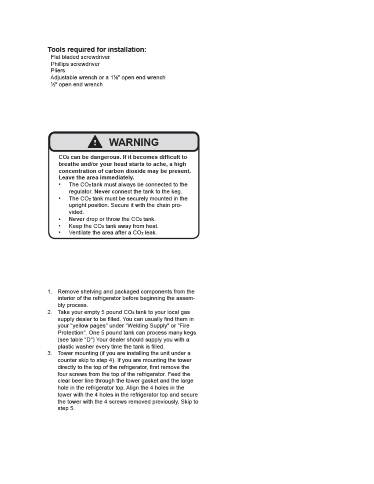
112
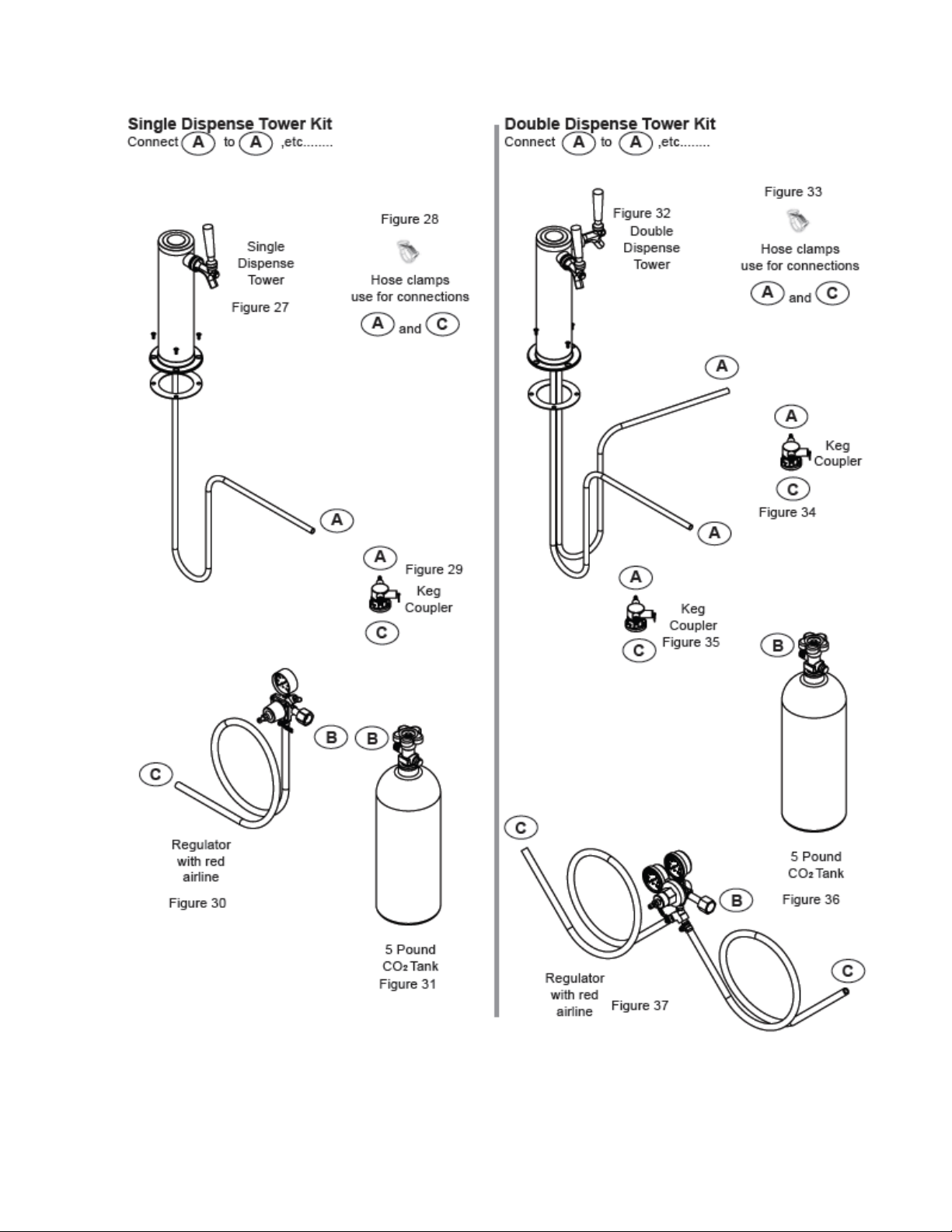
113
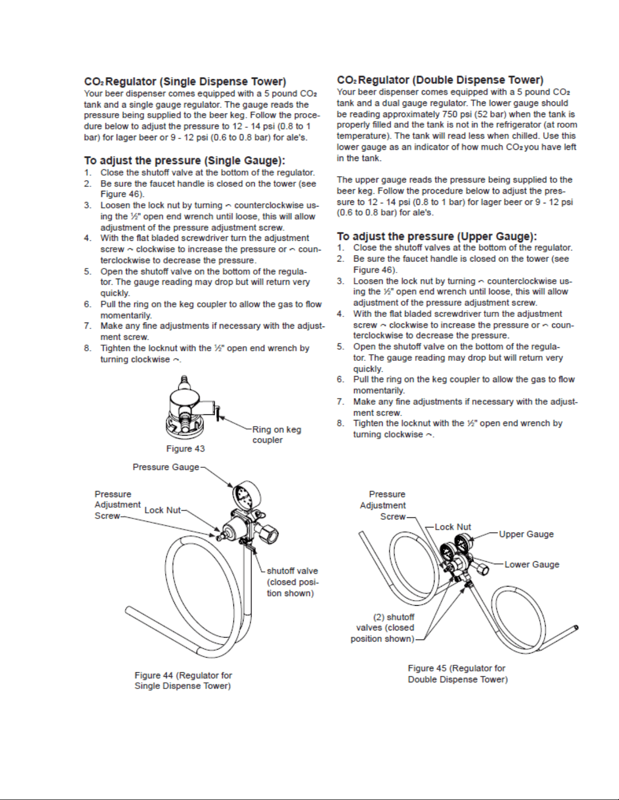
114
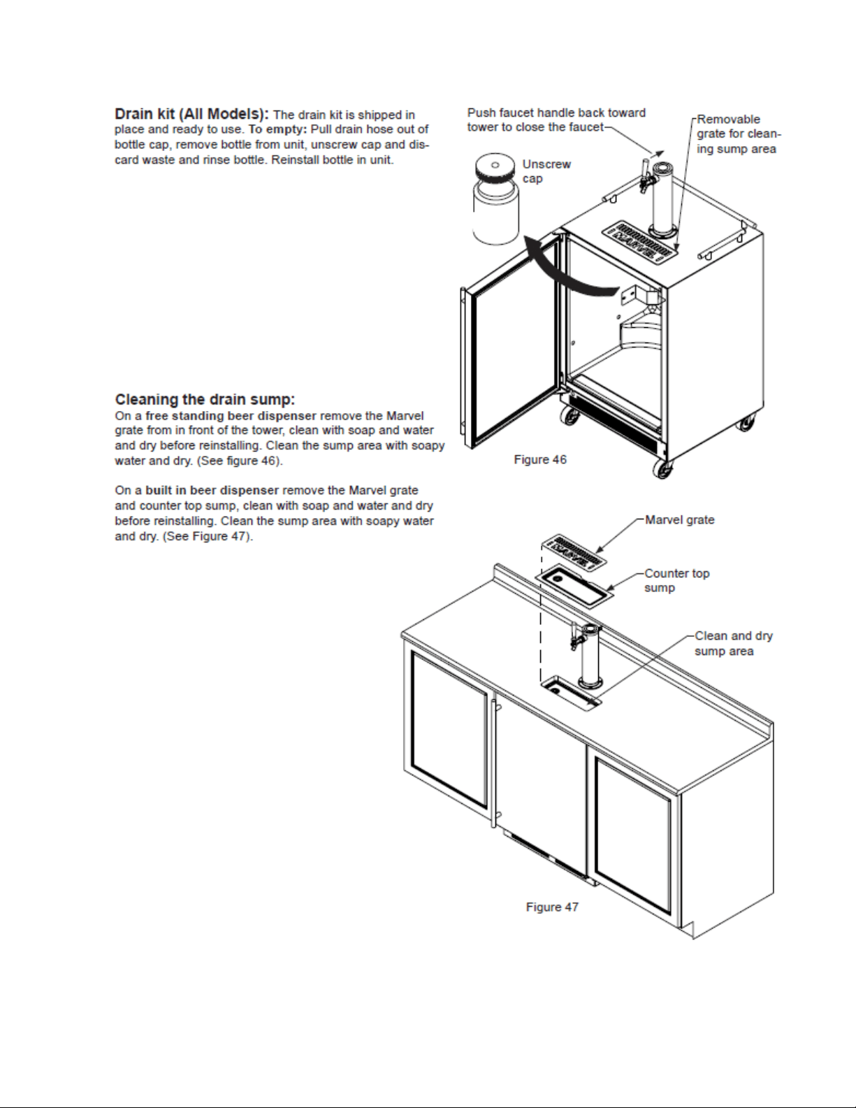
115
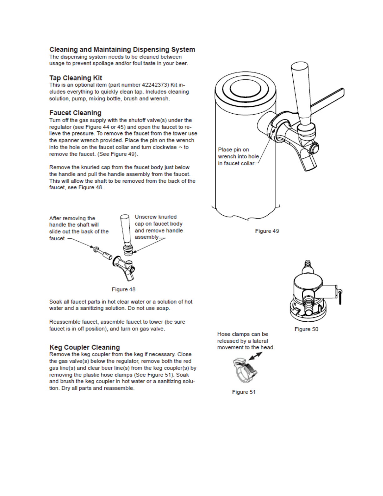
116
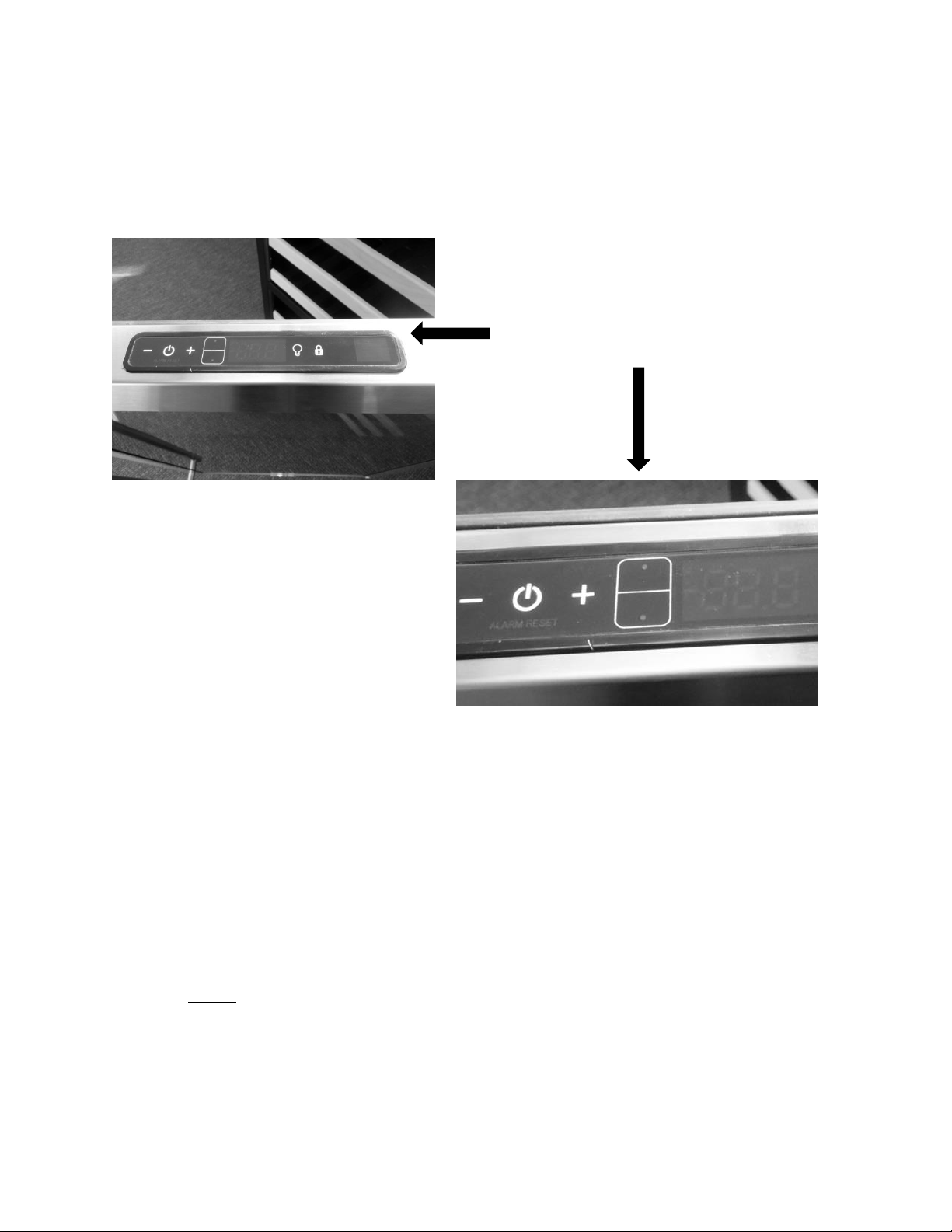
117
Section 15: Dual Zone
15.1: User Interface Control
Refer to Section 5.4 of this manual for more specific control reference
15.2: Operation
TEMPERATURE CONTROL OF THE DUAL ZONE COMPARTMENTS
Colder temperature is maintained per the SETPOINT for the lower compartment. Temperature
is achieved and maintained by cycling the compressor on and off to reach the desired
SETPOINT temperature.
Warmer (upper zone) temperature is maintained per the SETPOINT by opening and closing
both damper doors along with the heat generated by the 20 watt AC heater located behind
the upper compartment access cover.
A call for cooling will open up both compartment dampers for tempered cold air throughout
the unit. NOTE: When the upper damper is open for cooling, the small air louvers in the upper
compartment will be closed, as evidence of the grey foam tape sealing against the rear of the
louver openings. The tempered air will be expelled through the circulation fan.
A call for heating in the upper compartment will close the upper damper into the lower
compartment. NOTE: When the upper damper is closed for heat, the small air louvers in the
upper compartment will open, as evidence of the grey foam tape opening away from the rear
User Interface Display: Features dual
compartment temperature set point
option on display.
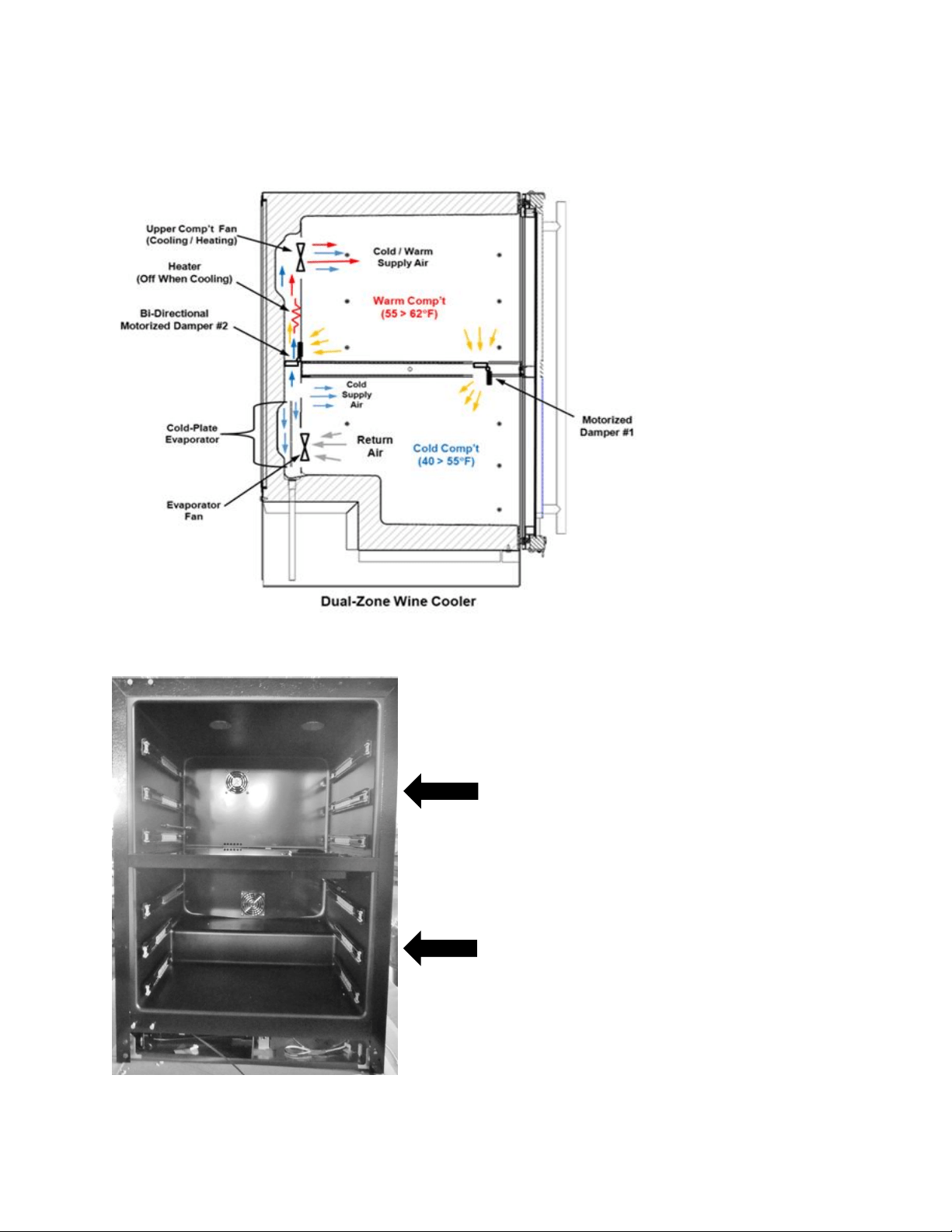
118
louver openings. The warm air will be circulated throughout the upper cabinet through the
upper circulation fan and return through the louvered opening at the bottom of the rear back
panel.
15.3: Characteristics
Upper Compartment:
Temperature range is 55° to 62° F.
Lower Compartment:
Temperature range is 45° to 55° F.
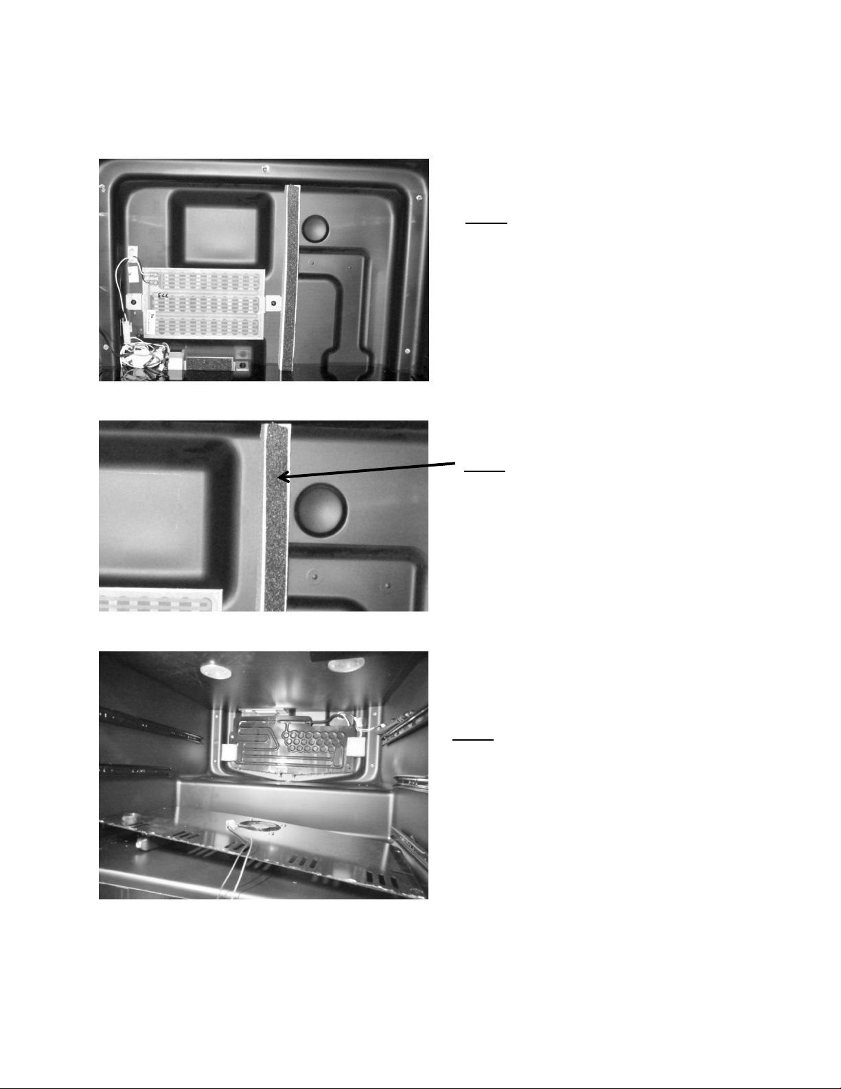
119
15.4: Dual Zone Compartment Air Flow
VIEW: Upper compartment with rear panel
removed. Center divider is in place.
VIEW: Lower compartment with rear panel
removed. Center divider is in place.
VIEW: Styrofoam air channel insert.
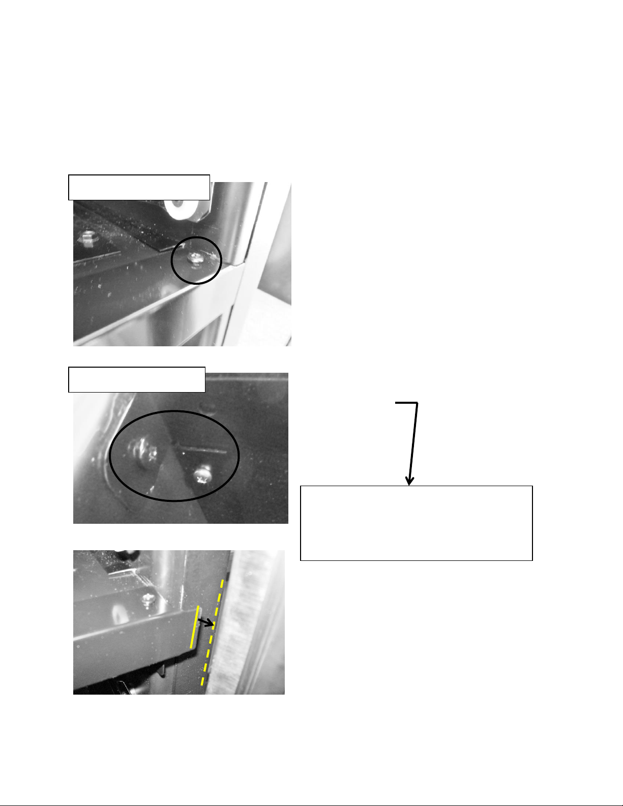
120
15.5: Divider Removal
This procedure would be required for an evaporator replacement.
Prior to removing the center divider the back cover to the upper compartment must be
removed, and the wire harnesses disconnected.
Mullion: Upper View
Mullion Bottom View
Remove both bottom and top screws
on each side of mullion.
The top screw must be removed so
that the mullion face can be
removed from the divider to obtain
door clearance.
Once the mullion face is removed, the divider
can be slid forward and out of the cabinet.
The dotted lines in the bottom photo show
the point where the mullion edge and
door will interfere if the divider is removed
prior to mullion face removal.
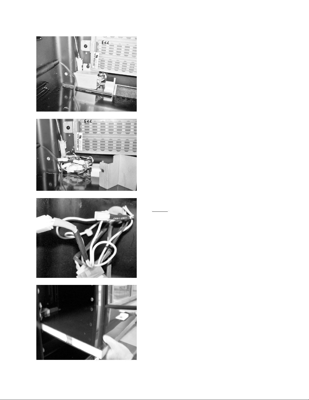
121
Remove the cover which isolates
the electrical connectors.
Disconnect wire
connectors.
Slide divider outward from cabinet.
NOTE: Each wire with a connector is
labeled with a piece of shrink wrap tubing
in regards to its termination point.
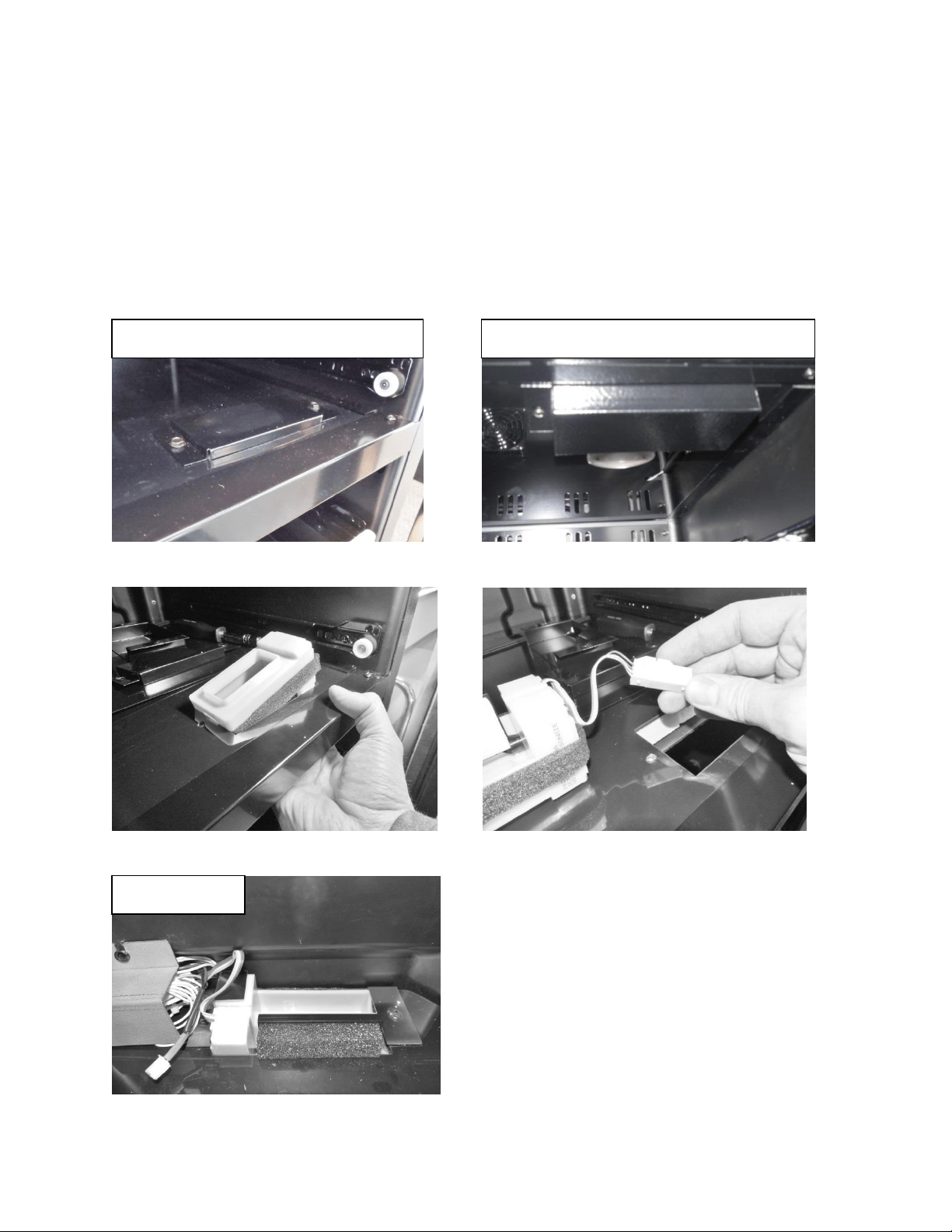
122
15.6: Damper Operation
The front damper is located in the font right hand side of the divider.
The rear damper is located in the rear of the divider behind the back cover.
Both damper positions are regulated by the need to cool or add heat into the
upper (warmer) compartment.
Front Damper – Upper View
Rear Damper
It is recommended to remove the
divider to access the rear damper.
Front Damper – Bottom View
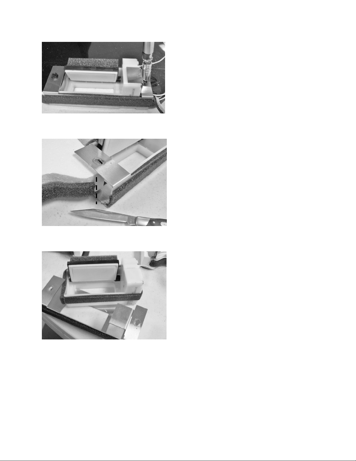
123
Remove damper from bracket.
Cut the foam insulation on each
side of damper bracket.
Remove screw on each side of
damper bracket.
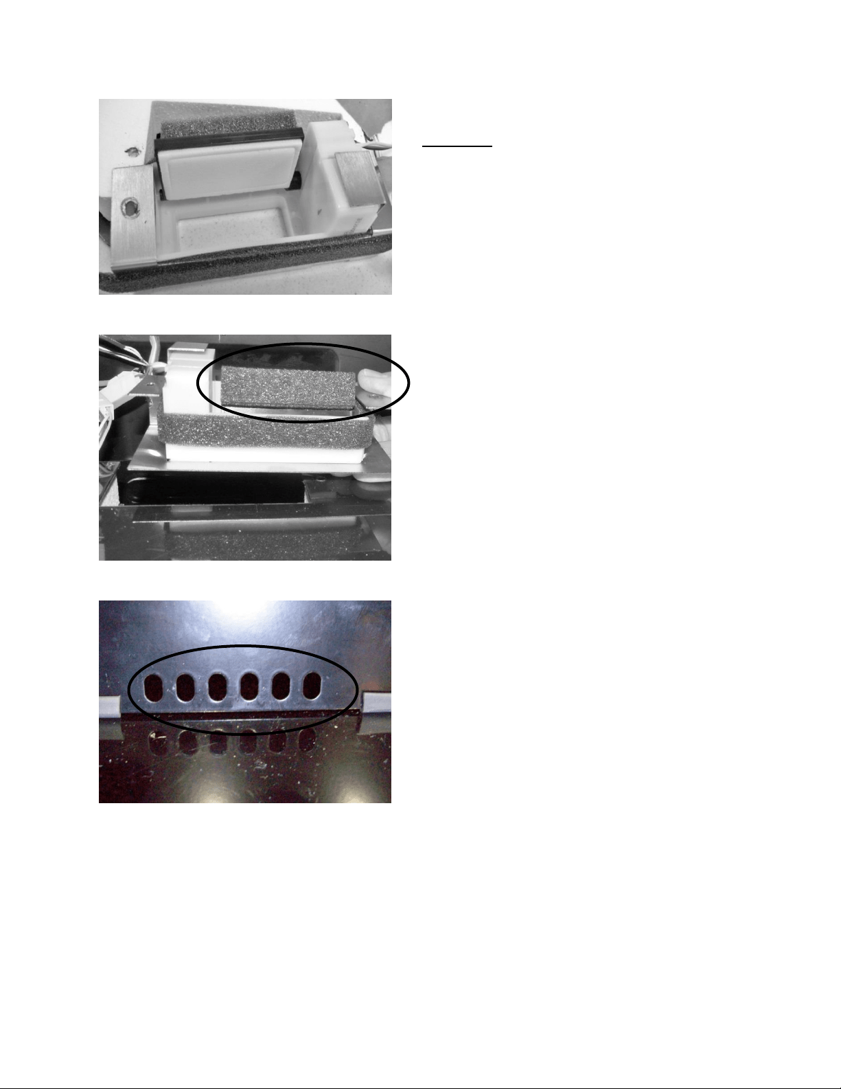
124
Rear View: Rear damper in the open
position.
Front View: Rear damper in the open
position: NOTE the insulation on the
back of the damper door.
View from the Upper Compartment: The
louvers on the back cover will be shut
when the rear damper is in the open
position. The insulation on the back of
the damper door will close air from
passing through.
The photo shows the upper damper
closed to the lower zone. This is the
orientation of the damper for the upper
zone once it reaches its set point.
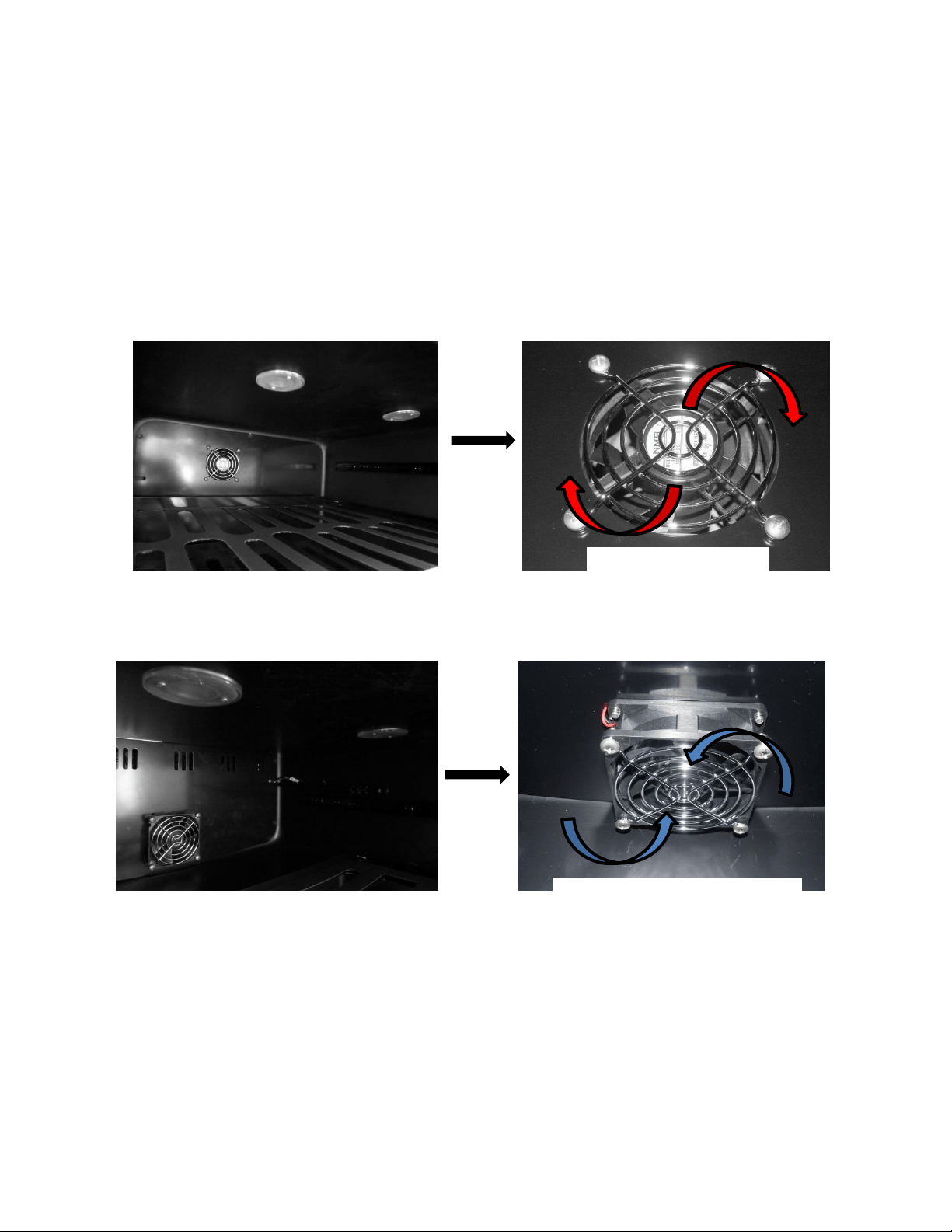
125
15.7: Compartment Fan Operation
Upper compartment; blows air out into the compartment, circulates supply air into the
compartment. The blade rotates in a clockwise rotation as you face the hub.
Lower compartment; draws air out of the compartment, return air is brought back into
the evaporator compartment to be reconditioned. The blade rotates in a counter-
clockwise rotation as you face the hub.
Top Compartment
Bottom Compartment
Clockwise Rotation
Counter-Clockwise Rotation
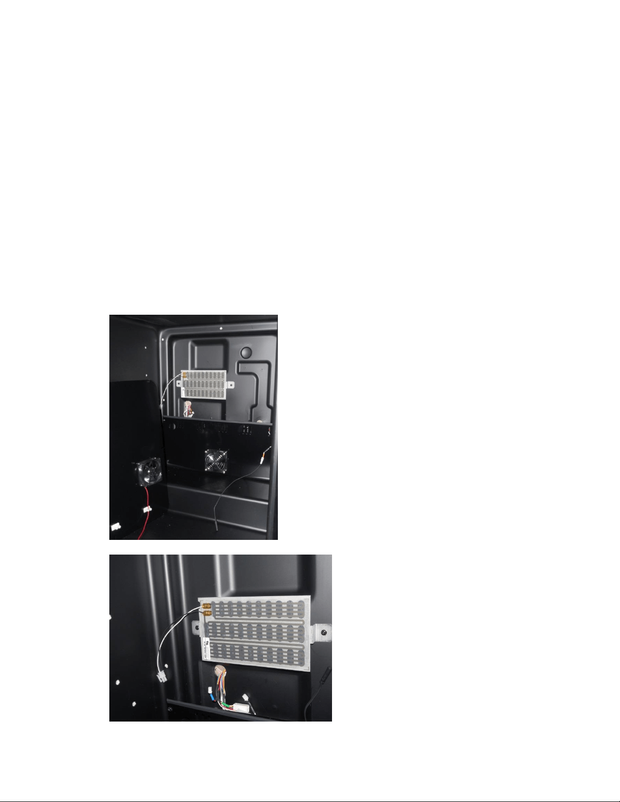
126
15.8: Heater Operation
The heater controls return air to circulate into the upper compartment to
maintain desired set point temperature.
A call for cooling in the upper (warmer) compartment opens both damper doors
and disables the heater.
A call for heat in the upper (warmer) compartment closes both damper doors
and enables the heater.
The heater is disabled when the ambient thermistor senses a temperature
excessive to 85°F.
o This prevents excessive compartment temperatures.
To access the heater (upper compartment) remove the 5 screws securing the rear panel cover.
Once this is done, remove the metal wire cover to access the fan connector. Once disconnected
the rear panel can now be removed from the compartment.
Upper Compartment Heater: Used to control and
maintain the temperature of the upper zone.
A replacement heater will appear as
seen to the left. The heater will come
attached to a replacement bracket.
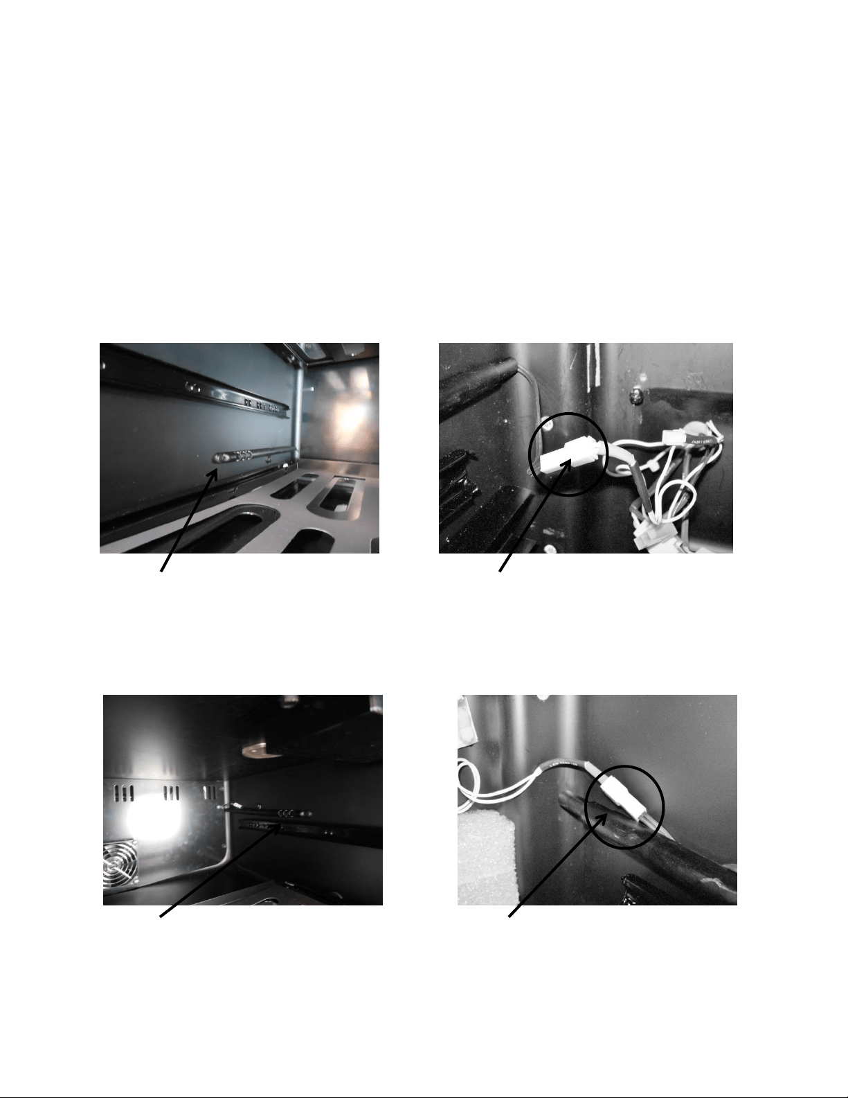
127
15.9: Thermistors
All temperatures are monitored individually by 10K @ 25°C NTC sensors (thermistor).
The dual zone has three thermistors, one for each compartment and a third mounted outside
the unit to sense ambient temperatures.
The ambient thermistor is located behind the toe grill and secured to the top of the machine
compartment. It is centrally located in the condenser intake air. If the ambient thermistor
senses a temperature above 85°F, the heater located in the upper compartment will be
disabled.
Upper View – thermistor is located on left hand side.
Bottom View – thermistor is located on right hand side.
Lower Thermistor Disconnect
Lower Thermistor Location
Upper Thermistor Location
Upper Thermistor Disconnect
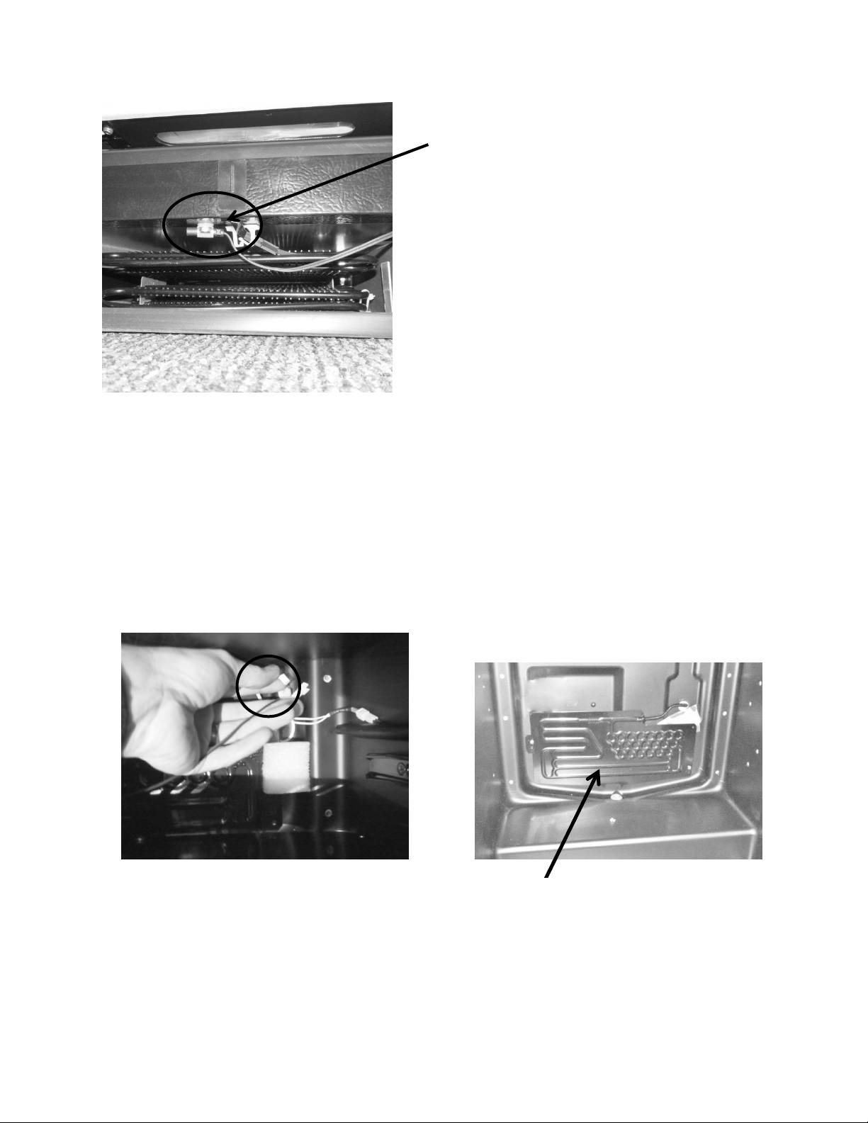
128
15.10: Evaporator Access
To access the evaporator (lower compartment) remove the 4 screws securing the
evaporator cover. Once the cover is removed the top of the cover can be lowered. At
this time, reach behind the cover and disconnect the evaporator fan. The cover can now
be removed from the compartment.
Location of ambient thermistor is
located behind the toe grill and
secured to the top of the machine
compartment, centrally located in
the condenser intake air.
The evaporator is located
behind the bottom back panel.
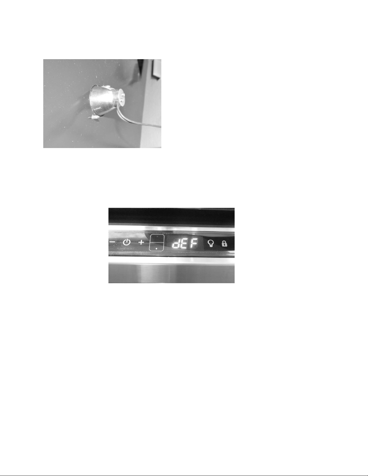
129
15.11: Interior LED’s
15.12: Defrost / Drip Time
When defrosting (dEF), the user interface display will appear as seen below:
Defrost can be achieved either automatically or manually. A manual defrost can be activated by
holding the minus and lock keys simultaneously for a period of three seconds. Once defrost is
activated the Use Interface will flash “dEF” three times before showing an uninterrupted “dEF”.
More information is available in Section 5.
The Dual Zone does not have a true defrost time. Defrost is achieved by an extended
compressor “Off” time. This compressor “Off” time is called “drip time”.
The dual zone does not have a termination thermistor attached to the evaporator plate to
terminate defrost. The defrost time is programmed into the control board for a period of 30
minutes; this is called “drip time”.
Another difference between the dual zone and other Marvel under counter appliances is the
length of “DRIP TIME” allowed. The drip time is associated with defrost “Off” time in that it
allows the moisture to clear from the evaporator plate to eliminate refreezing once the
compressor restarts.
This is a photo of the bottom compartment LED. It was
taken after the divider was disassembled. It references
the need to carefully finger tighten the bulb when
replacing. No clips or backers are used for assembly.
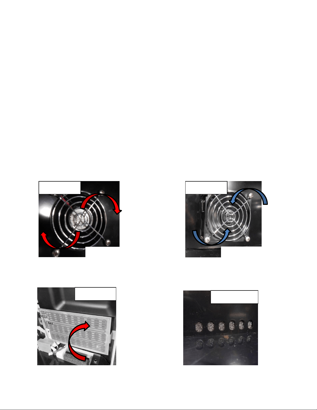
130
The defrost cycle is pre-programed into the main power board and is not adjustable. The
factory default is 6 hours of accumulated run time and begins at the conclusion of the
compressor on cycle. The beginning of the next defrost cycle starts after time expires from the
previous defrost event.
15.12.1: Defrost Component Sequence
1. The heater cycles between on and off depending on the call for cooling load (unless
ambient temperature exceeds 85°F).
a. A call for cooling in the upper (warmer) compartment opens both damper doors
and disables the heater.
b. A call for heat in the upper (warmer) compartment closes both damper doors
and enables the heater.
2. The compressor shuts off at the initiation of the defrost cycle.
3. Both upper (Photo A) and lower (Photo B) compartment fans will be operative.
4. The rear damper is open from the heater section to the evaporator section (Photo C);
but closed to the top compartment to the heater (Photo D).
Upper
Lower
Damper Open
Damper Closed
Clockwise Rotation
Counter-Clockwise Rotation
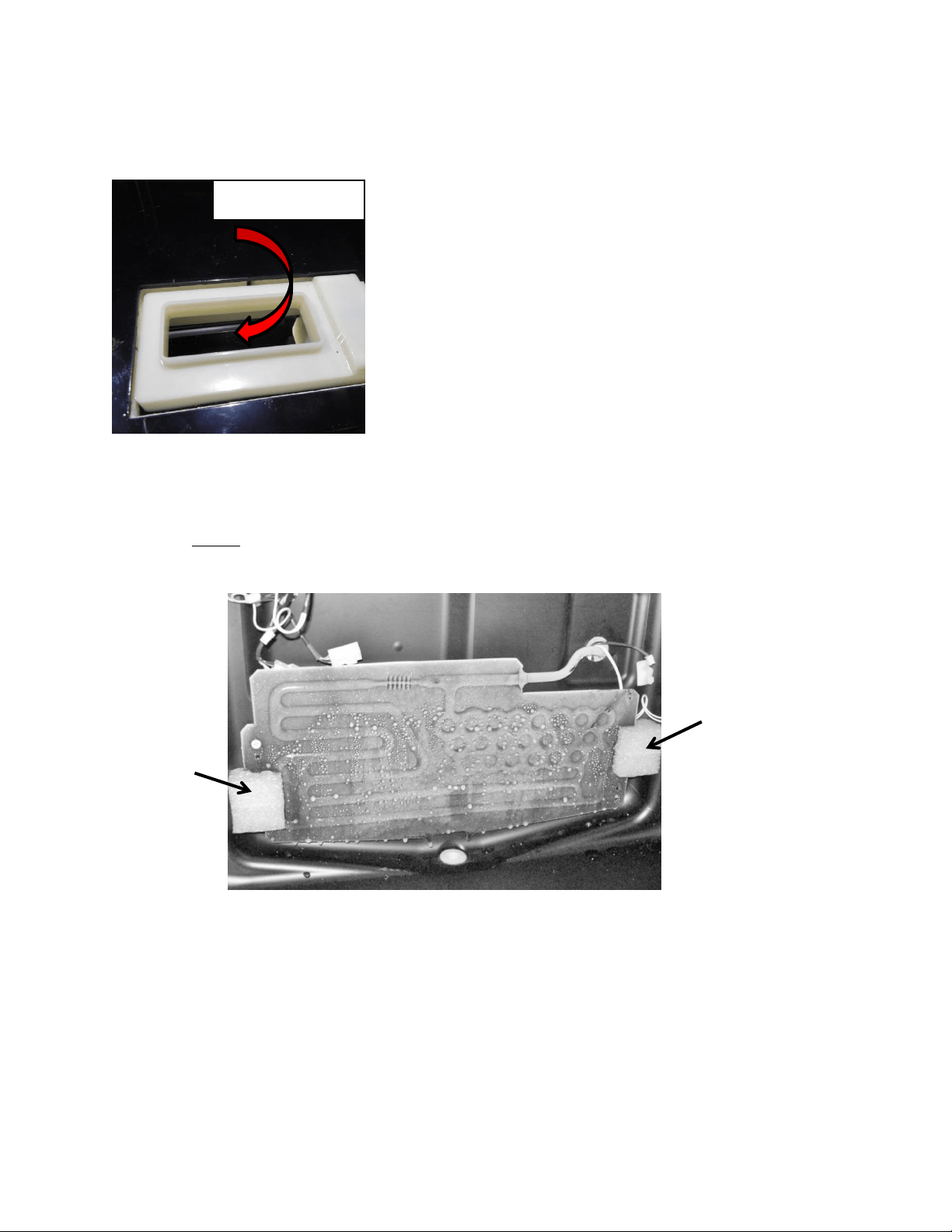
131
5. The front damper remains open, to circulate air from the lower compartment to the
upper compartment (Photo E).
The photo below shows water droplets starting to build up on the evaporator plate.
NOTE: This photo does not represent a failure condition as it appears.
15.13: Refrigeration and Mechanical
The basic refrigeration and mechanical operation and assembly are not unlike that
discussed earlier in this manual. This information can be reviewed in chapters 3 and 4.
Foam
Spacer
Foam
Spacer
Damper Open
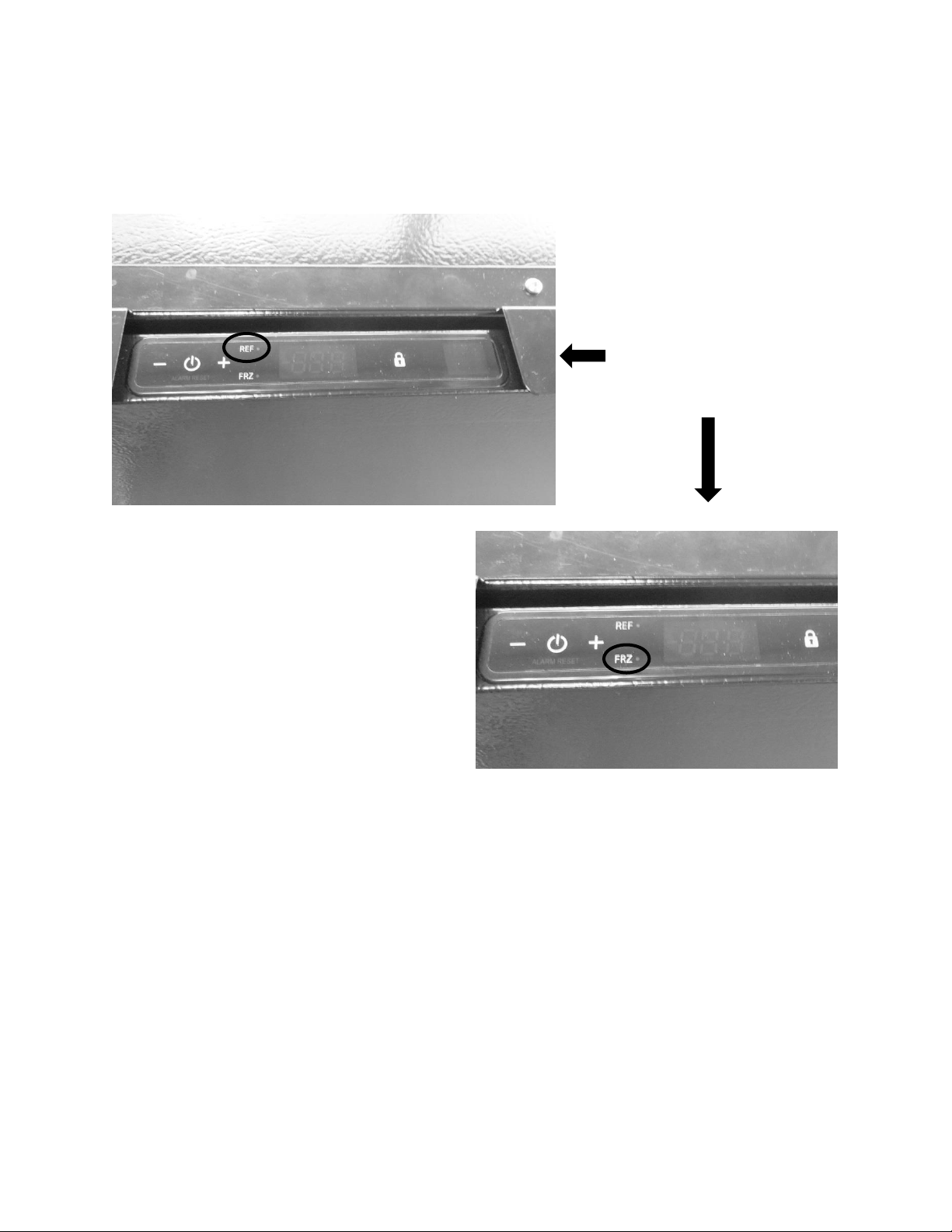
132
Section 16: Refrigerator Freezers
16.1: User Interface Control
16.2: Operation
TEMPERATURE CONTROL OF THE REFRIGERATOR AND FREEZER COMPARTMENTS
The Aurora Intuit control regulates the refrigerator and freezer compartment temperatures
separately.
Freezer temperatures are monitored by a thermistor located on the upper left hand side of the
tempered compartment. The compressor will run until the thermistor senses the desired
“Freezer Set Point” on the user interface, then shuts off.
The refrigerator temperature is also thermistor monitored; the thermistor is located mid-wall
on the right hand side of the compartment. The thermistor works in conjunction with a
User Interface Display: Features
dual compartment (refrigerator
and freezer) temperature set
point option on the display.

133
motorized damper; this damper is located on the bottom rear wall separating the freezer and
refrigerator compartments. When the refrigerator compartment thermistor senses
temperatures above the “Refrigerator Set Point” on the user interface, the damper will open.
The open damper allows for cold air to be circulated from the evaporator, through the freezer
door, into the refrigerator, and back through the damper to satisfy the need for cooling. Once
the refrigerator thermistor is satisfied, the damper will close.
The top of the freezer compartment door has a narrow slot that is used to supply tempered air
from the freezer compartment into the refrigerator compartment. The air is then circulated
through the refrigerator compartment and returned through the open damper into the
evaporator compartment to be recirculated after it passes through the evaporator.
Both the refrigerator and freezer fans run simultaneously when the compressor is running, both
are inoperative during the compressor off cycles and also when the cabinet door is opened.
When running, the freezer fan pressurizes the freezer compartment and forces air into the
refrigerator compartment through the slot located in the top of the freezer door. Then the fan
is inoperative, very little air migrates from the freezer to the refrigerator compartment.
The refrigerator fan is located in the rear left hand corner, directly underneath the freezer
compartment. Its purpose is to circulate air from underneath the freezer section, upwards and
around the shelving and back through the return air damper.
16.3: Characteristics
All control functions are identical to those incorporating the Aurora Intuit Control. Reference to
section 5.4 of this manual will familiarize control navigation.
Colder compartment temperature is maintained by cycling the compressor on and off.
Internal cold compartment temperature is monitored by the compartment thermistor.
Warmer compartment temperature is maintained by opening and closing a damper
door. A 300 watt heater is used for auxiliary heat.
WARNING: Prior to any electrical repair the appliance must first be disconnected
from its power source.
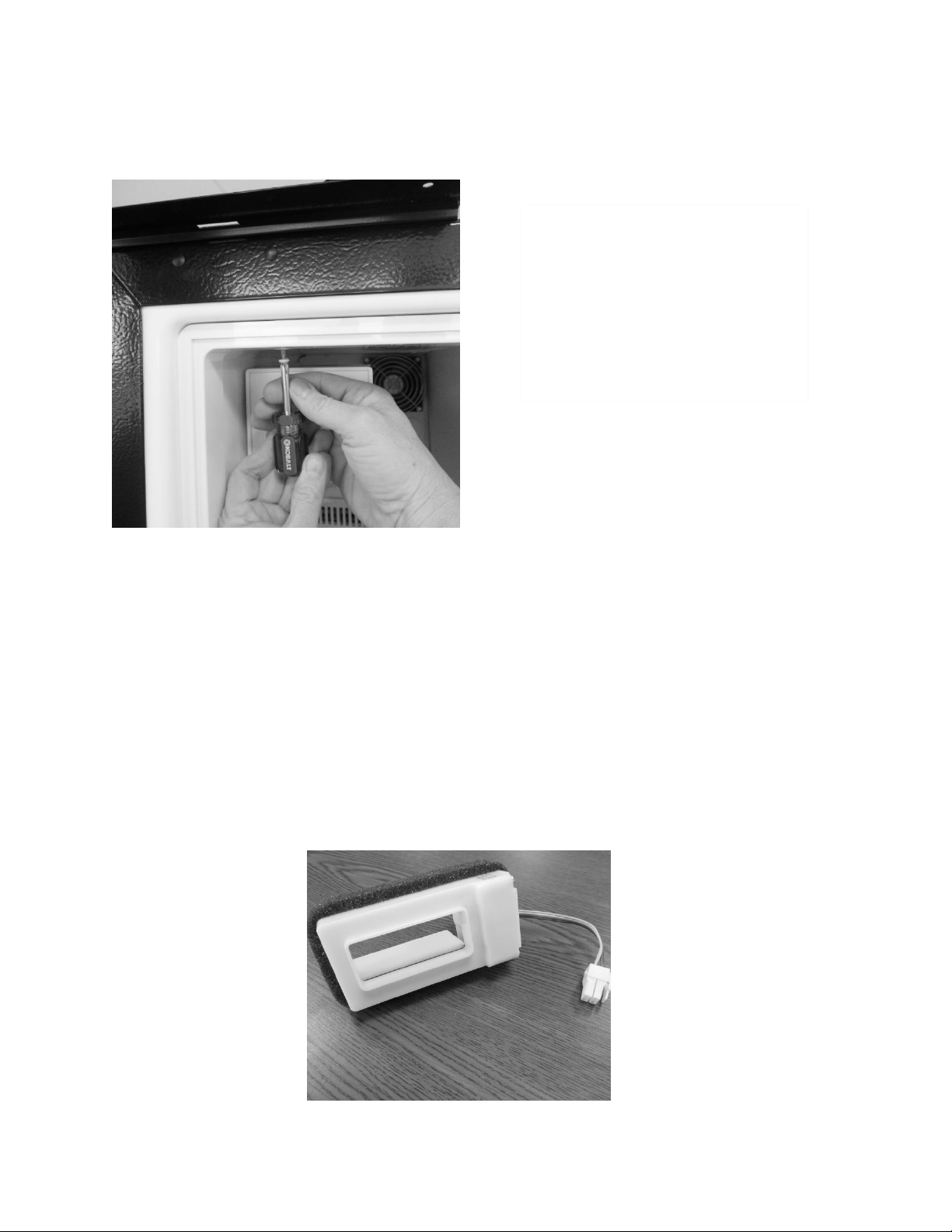
134
ACCESSING THE EVAPORTOR COMPARTMENT
16.4: Damper Operation
12VDC / bi-polar stepper motor
16.4.1: Damper Access
Warmer compartment temperature is maintained by opening and closing the
damper in conjunction of the 300 watt heater.
Colder compartment temperature is maintained by cycling the compressor on and
off.
The damper to the fresh food compartment will close during defrosts. This serves as
a dual purpose; it will concentrate more heat for clearing the evaporator while also
eliminating any residual heat transferring back to the fresh food compartment.
To access to the freezer / evaporator
compartment, first remove the
freezer door and frame assembly.
This will total 6 screws, 5 on the
inside perimeter of the door frame,
another on the inside upper left hand
corner.
Damper shown in
the open position.
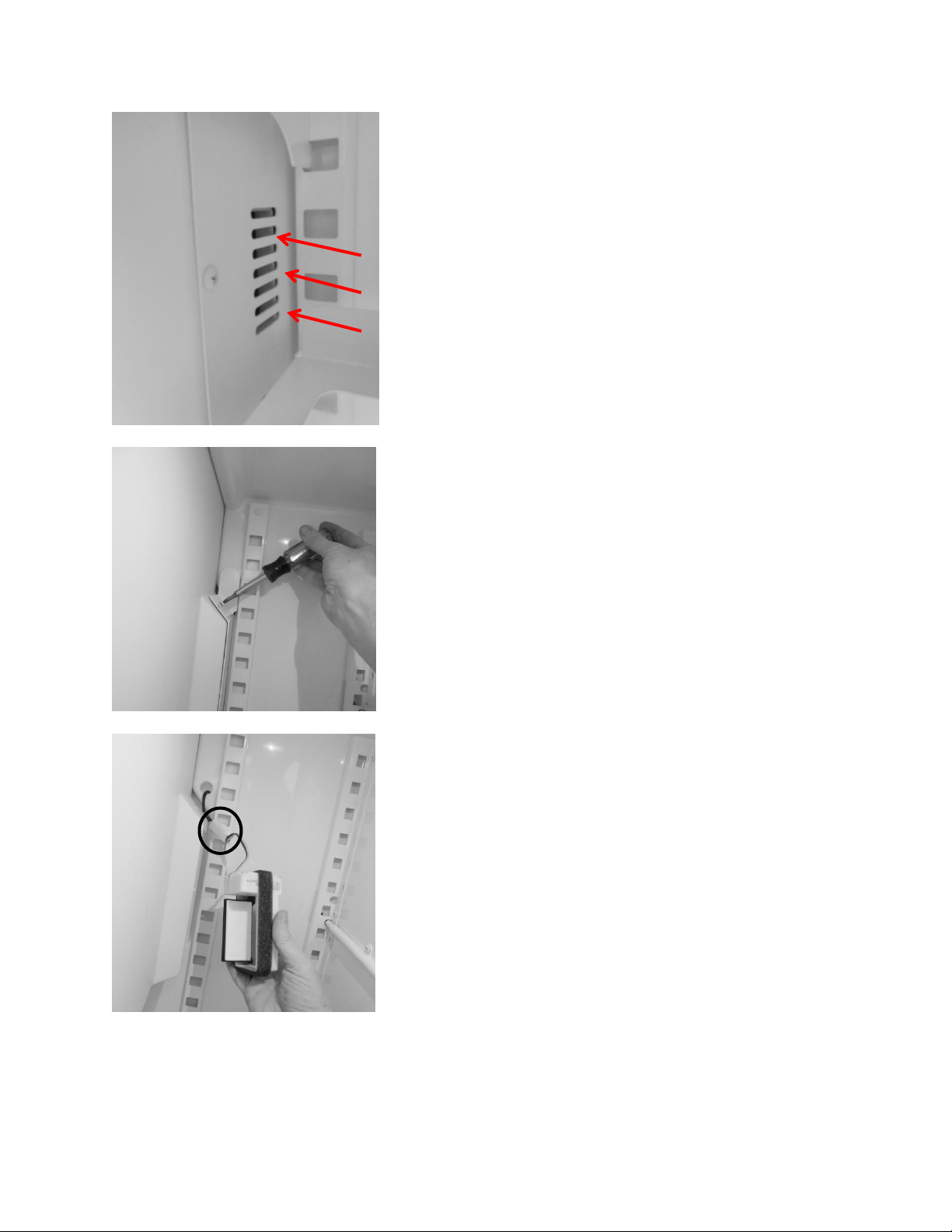
135
AIR FLOW
Air transfer damper is located
behind this louver cover.
To access the damper, remove all
three screws from the cover face.
The damper can be grasped and
pulled out of the opening.
Disconnect the wire connector to
replace.
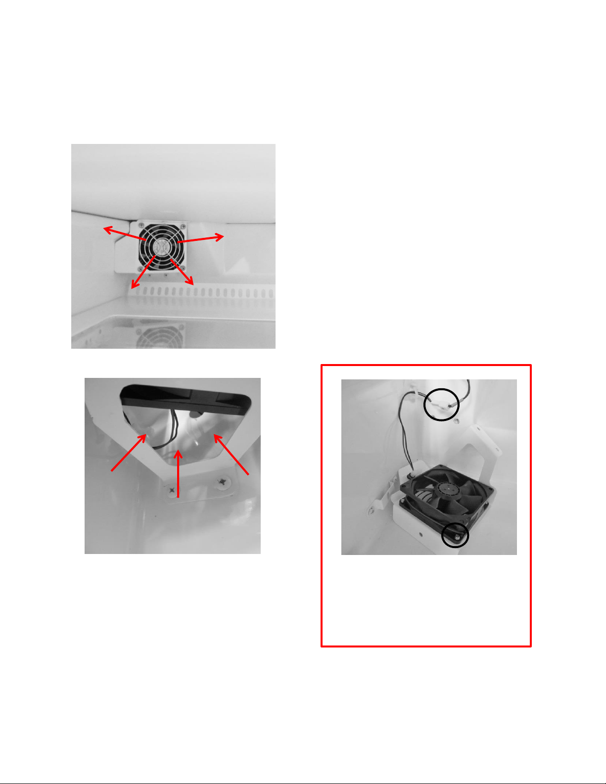
136
16.5: Fan Operation
16.5.1: Refrigerator Supply Fan
6-13.8 VDC
AIR FLOW
AIR FLOW
The bottom of the fan assembly is open to
recirculated air from the compartment. The
air is then pushed out into the compartment
through the fan blade.
To replace the fan motor; the fan assembly
must be removed and disassembled. Two
screws are seen in the photo and one is in the
upper flange (not shown).
The refrigerator fan is located
underneath the freezer
compartment in the left rear corner.
To replace the fan, drop the fan shroud,
disconnect the wire connector (1) and
remove all four screws (2) where the fan
grill, shroud and fan are assembled.
1
2
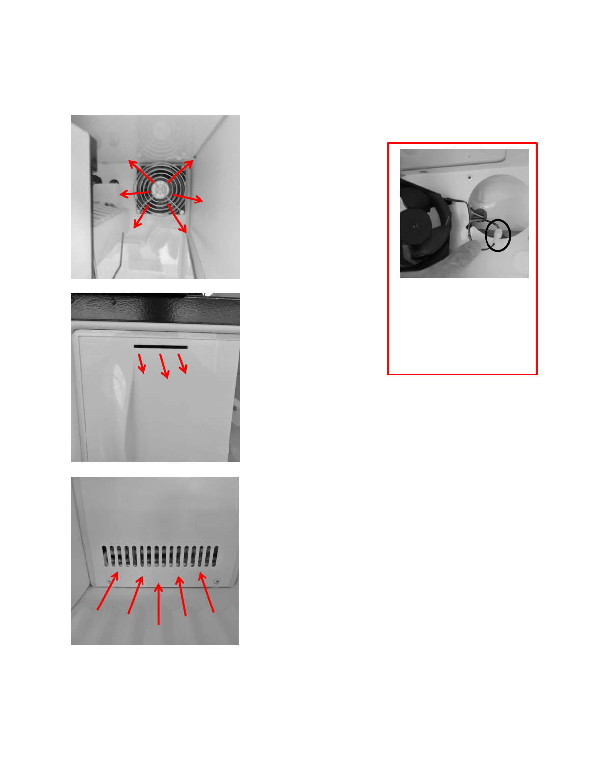
137
16.5.2: Freezer Supply Fan
6-13.8 VDC
Supply Air Fan:
Circulates tempered
air into the freezer
compartment.
Louvers in the bottom of
the evaporator cover
accommodate return air
back to the evaporator
compartment.
Supply air is
transferred from the
freezer into the
refrigerator section
through the slot in
the freezer door.
AIR FLOW
AIR FLOW
AIR FLOW
To replace this fan motor,
remove all four screws holding
the grill and the motor to the
evaporator cover. Pull fan out
and disconnect the wire
connector.
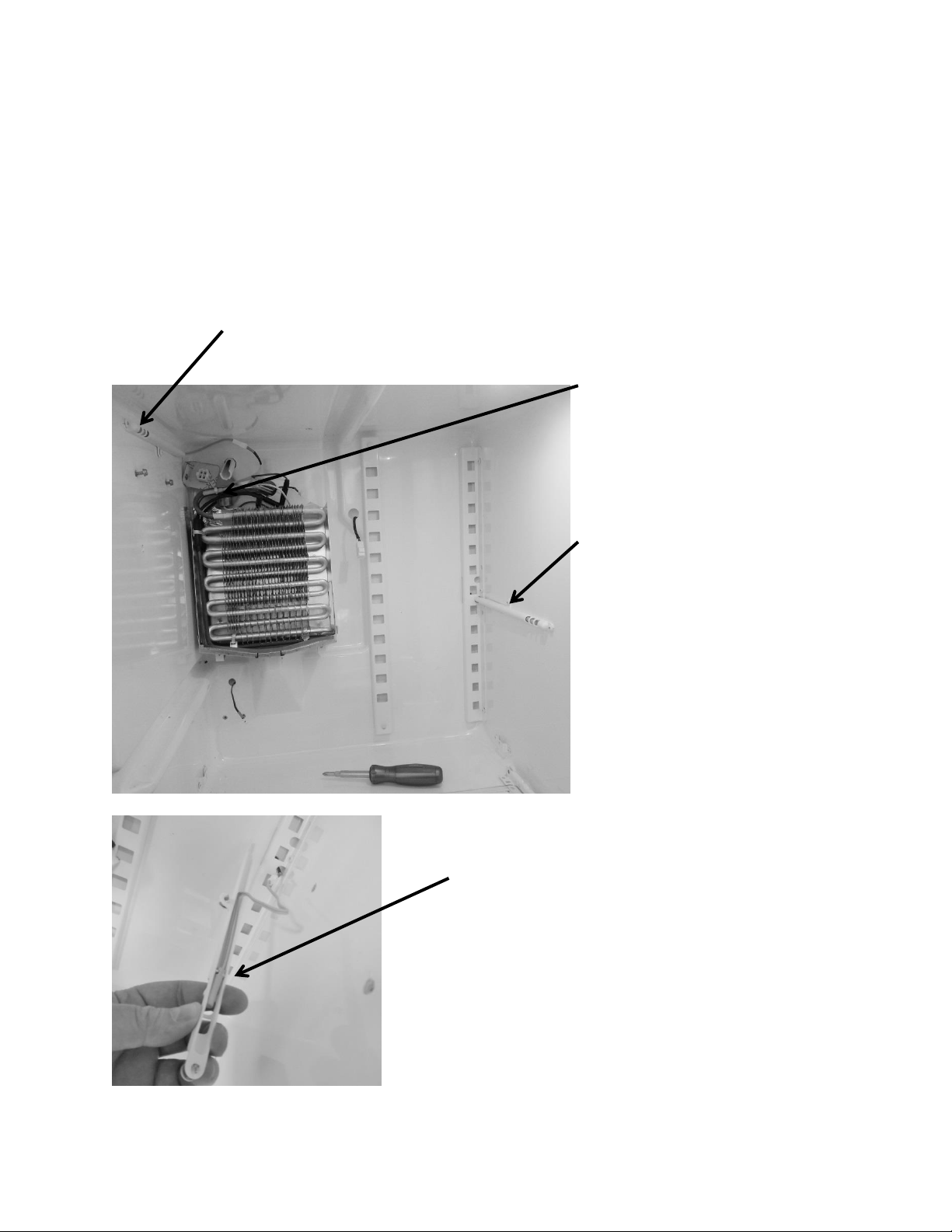
138
16.6: Thermistors
16.6.1: Type
NTC, 10K @ 25°C, same as discussed in Section 6 of this manual; Use the same
resistance charts located in Section 6.4.
16.6.2: Location
The freezer compartment thermistor is mounted on
the upper left hand wall of the freezer side wall.
The refrigerator compartment
thermistor is mounted on the mid wall
on the right hand side of the
refrigeration section.
The defrost thermistor is mounted on
the evaporator outlet. The evaporator
is located behind the freezer
compartment.
The thermistor bulb is located with the notch on
the lower bulb which will nest inside the locating
clip on the inside of the thermistor shield.
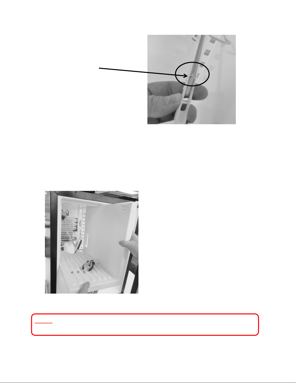
139
16.7: Refrigeration and Mechanical
The basic refrigeration and mechanical operation and assembly are not unlike that
discussed earlier in this manual. This information can be reviewed in Chapters 3 and 4.
NOTE: Refer to Section 19 for a Service Bulletin regarding replacement of the
Evaporator / Heat Exchanger.
The freezer partition can easily be
removed for access to the evaporator
section. Remove the three screws
from the taps (2 on the top vertical
and 1 on the left horizontal corner)
where they are screwed into the
cabinet.
This view shows the thermistor bulb nested
inside the shield.
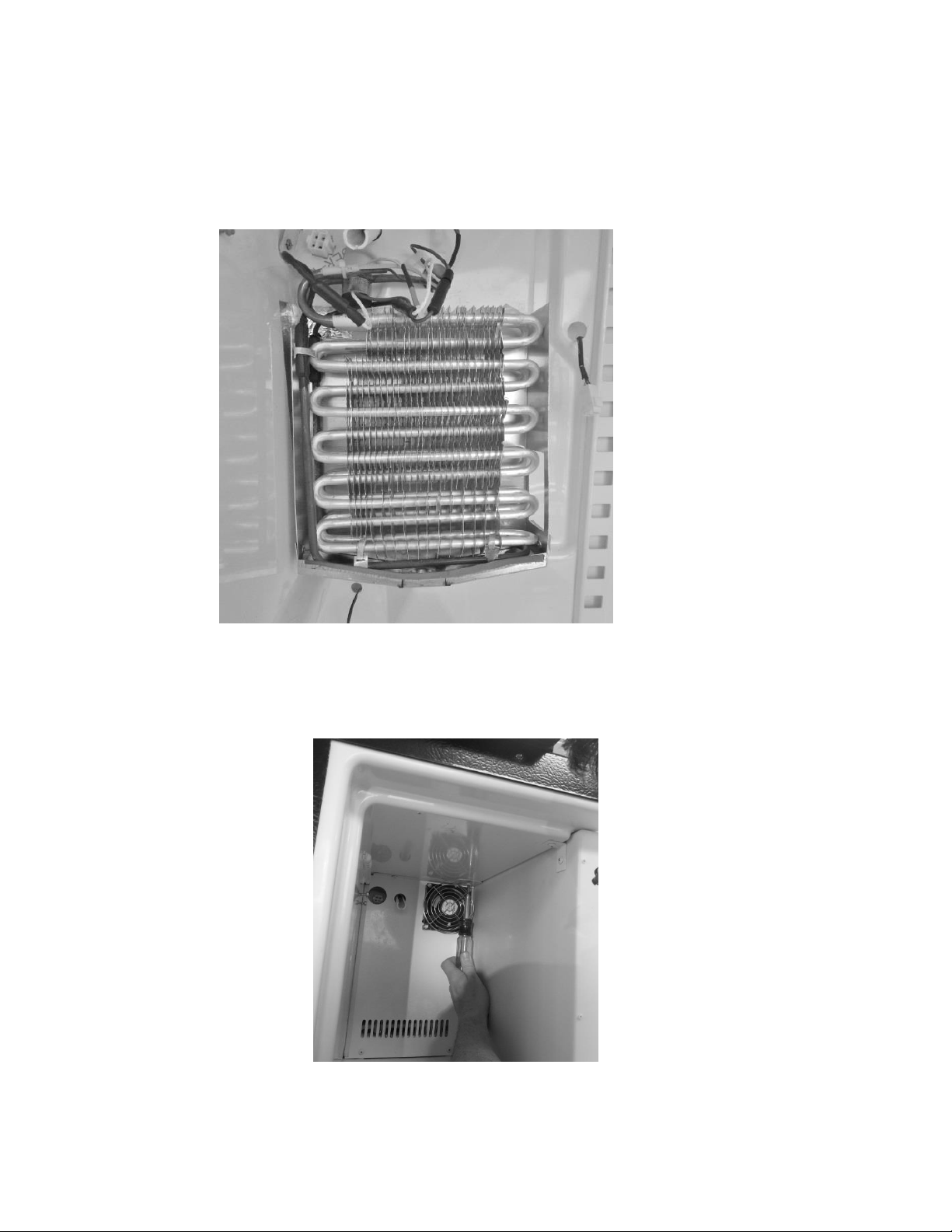
140
16.8: Evaporator
16.8.1: Type
Fin and Tube.
16.8.2: Location
Located behind the freezer compartment.
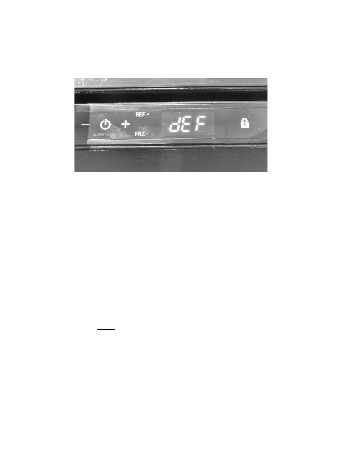
141
16.9: Defrost
When defrosting (dEF), the user interface display will appear as seen below:
Defrost can be achieved either automatically or manually. A manual defrost can be activated by
holding the minus and lock keys simultaneously for a period of three seconds. Once defrost is
activated the Use Interface will flash “dEF” three times before showing an uninterrupted “dEF”.
More information is available in Section 5.
Defrosting of the refrigerator freezer is unique from any of the Marvel and Marvel
Under counter products. The components are very similar to those in a domestic
full size refrigerator. The system includes a defrost heater, defrost thermistor, and a
defrost termination thermostat.
The damper to the fresh food compartment will close during defrosts. This serves as
a dual purpose; it will concentrate more heat for clearing the evaporator while also
eliminating any residual heat transferring back to the fresh food compartment.
The timer function is programed into the main control board.
o The defrost cycle is programmed to activate after 8 hours of compressor run
time.
o NOTE: In a 90°F ambient, a typical defrost time will average approximately
17 minutes from compressor off, to compressor on time.
16.9.1: Defrost Function
The defrost cycle is activated by a timed event from the main control board. The
programmed event will last for a 25 minute maximum defrost duration.
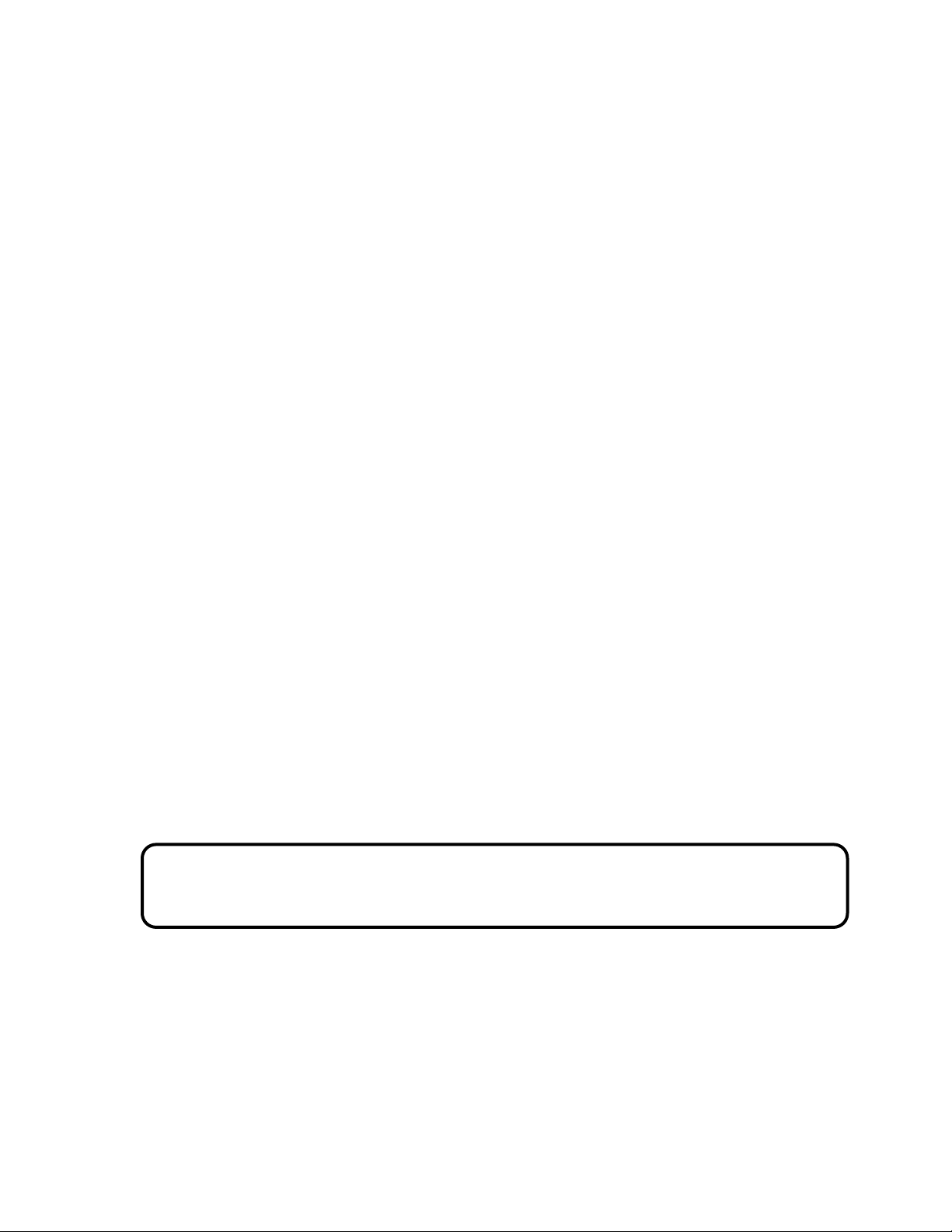
142
16.9.2: Defrost Heater
The defrost heater has a 300 watt rating.
The heater extends down the side and bottom of the fin and tube evaporator.
The primary heater will cut out at 45°F.
16.9.3: Defrost Thermistor
A defrost cut off thermistor acts as the primary method to terminate the defrost
event.
It is attached to the copper inlet tube of the evaporator.
The thermistor will terminate defrost at 45°F.
16.9.4: Defrost Termination Thermostat
The defrost termination thermostat acts as a secondary (safety) cut off for the
termination of the heater at the conclusion of the defrost event.
It is located at the copper outlet tube of the evaporator.
The safety cut out of this termination thermostat is set at 47°F.
16.9.5: Defrost Drip Time
Drip time is extended to the end of the defrost cycle to ensure that all water
droplets are drained off the evaporator coil to prevent refreezing.
The length of drip time is programmed at 10 minutes after the termination of the
defrost thermistor.
16.10: ACCESS TO THE DEFROST COMPONENTS
WARNING: Prior to any electrical repair the appliance must first be disconnected
from its power source.
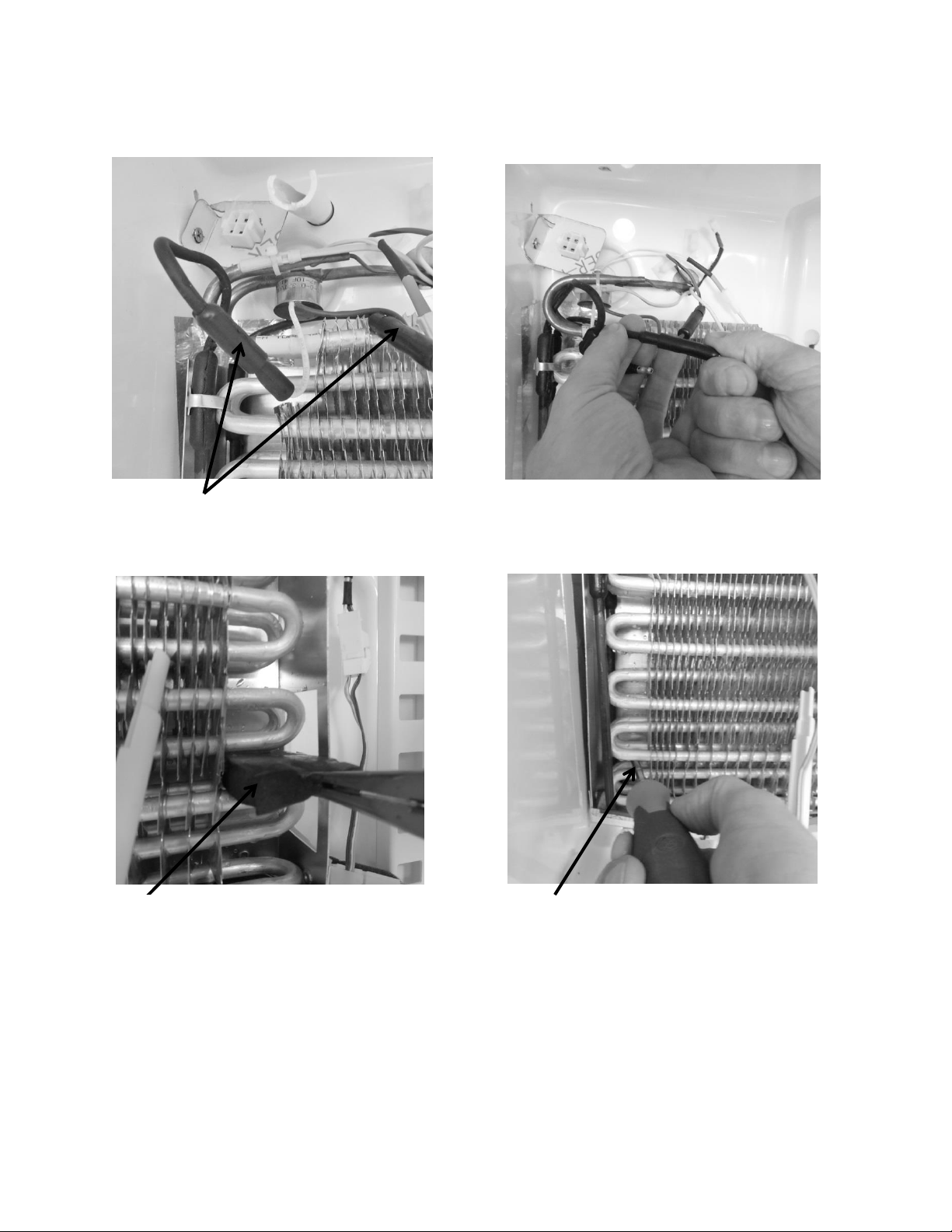
143
16.10.1: Defrost Heater
Locate defrost heater connections.
To replace defrost heater, unplug
the connections.
Remove the mastic evaporator
spacers.
Remove the four screws that secure
the drip pan to the liner wall
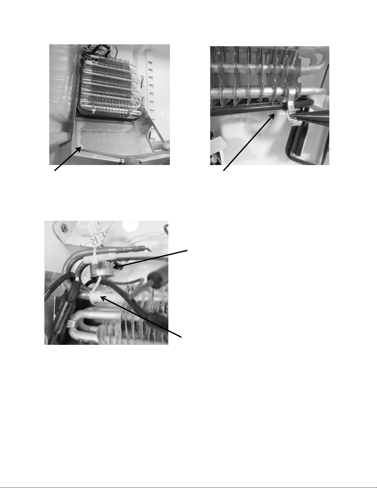
144
16.10.2: Defrost Termination Thermostat
16.10.3: Defrost Thermistor
Also seen in the above picture; the thermistor is attached to the evaporator inlet and secured
with a nylon zip tie.
To replace the defrost thermistor; disconnect the thermistor connector inside the evaporator
compartment and replace.
Remove the tin tie wraps that secure
the heater next to the evaporator.
Slide the drip pan down away from
the evaporator.
The Termination thermostat is
located on the evaporator outlet.
The Defrost Thermistor is located on
the evaporator inlet.
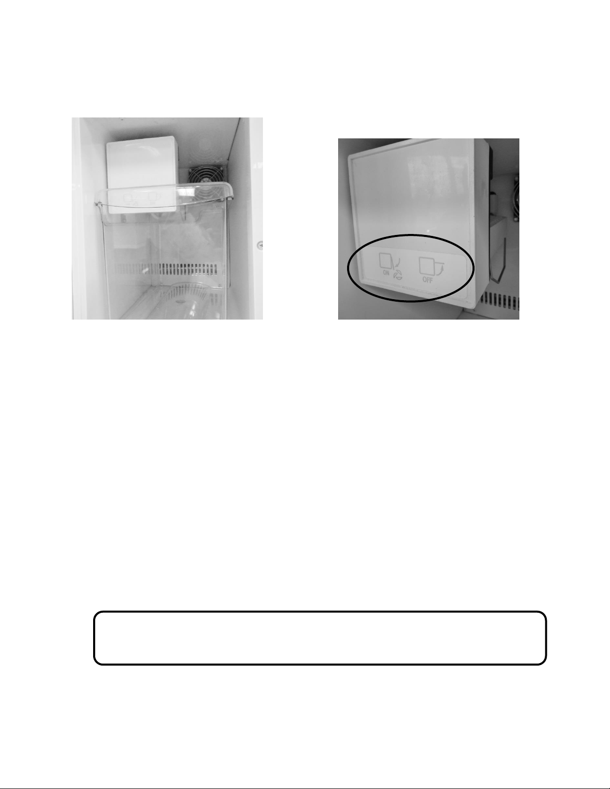
145
16.11: RFI (Refrigerator Freezer- Ice Maker)
16.11.1: Ice Maker
To remove the ice maker cover; insert a screwdriver into the bottom notch and lightly pry open.
16.11.1.1: Specs:
115 Volt/60 hertz
Heater: 165 Watts / 80 Ohms
Thermostat: Open @ 48°F (8.9°C) / Close @ 15°F (-9.4°C)
Flow Rate: .34 GPM
WARNING: Prior to any electrical repair the appliance must first be disconnected
from its power source.
Freezer compartment: Includes an ice
bucket and an ice maker with a fan in
the upper rear corner.
This diagram represents the position
of the ice machine level to turn the ice
maker ON or OFF.
Lever Up: Ice Maker “OFF”
Lever Down: Ice Maker “ON”
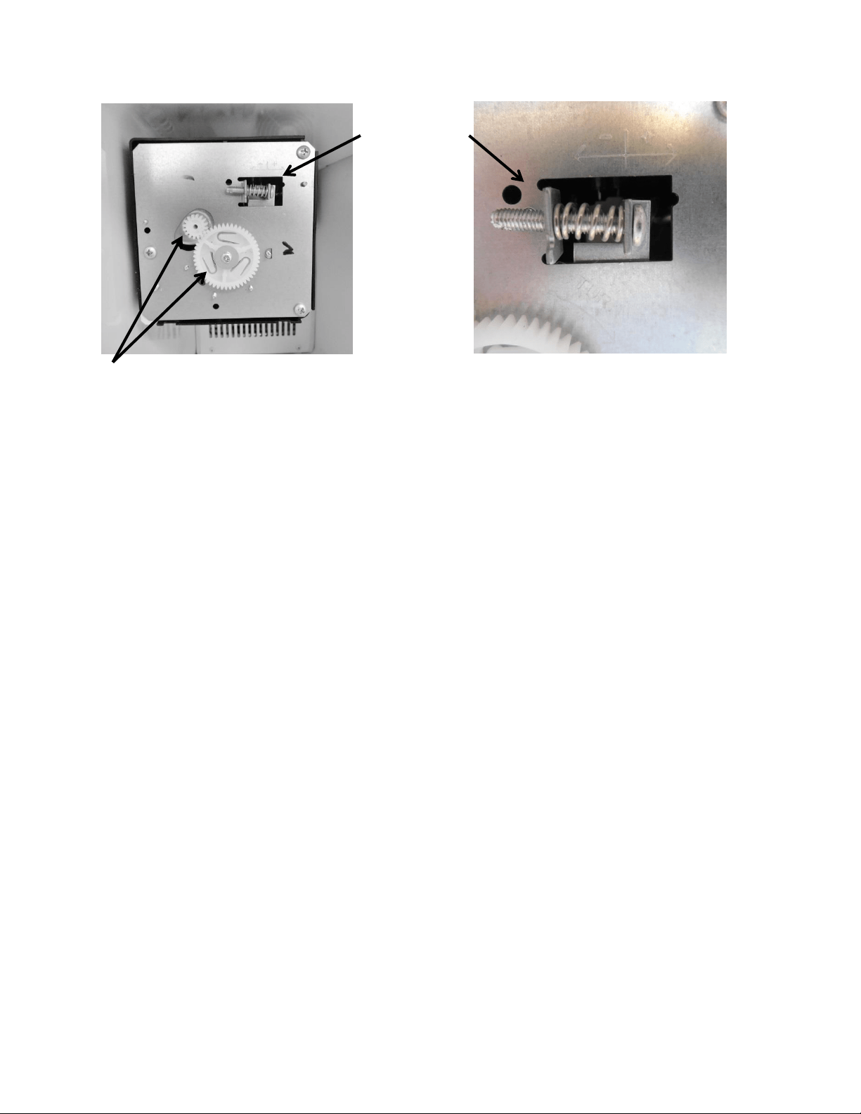
146
16.11.1.2: Ice Maker Test Cycling
Test cycling of the ice maker can be achieved by turning the motor gear counter-clockwise until
the holding switch circuit is complete. All components of the ice maker should function to
complete the cycle.
The timing gear should not be turned as this will damage the ice maker.
16.11.1.3: Water Flow Volume
The water fill adjustment screw will change the fill volume by changing the fill time. One full
turn is equal to 20cc (.68 oz.). The correct fill is between 90 and 120 cc (3.0 – 4.0 oz.).
When replacing a water valve, the fill volume must be checked.
These ice makers are factory preset for a flow rate of .34 gpm (gallons per minute).
PLEASE REFER TO THE SERVICE DATA SHEET INSIDE THE ICE MAKER COVER FOR
ADDITIONAL INFORMATION.
Adjusting the water fill can be
accomplished by turning the adjustment
screw clockwise (+) to increase or counter
clockwise (-) to decrease.
Fill Adjustment
Ice maker with the cover removed.
The motor gear is the small gear on the top left.
The timing gear is the largest gear in the center.
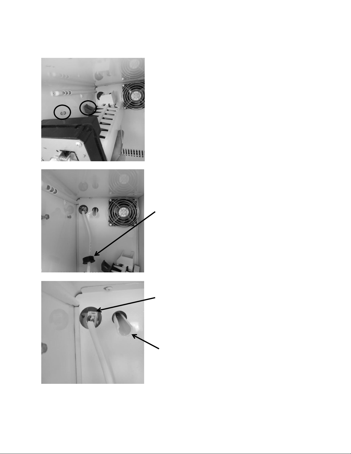
147
16.11.2: Ice Maker Removal
To remove the crescent ice maker, the
screws located inside the two upper
mounting brackets need to be loosened.
There is no need to remove these screws.
A third screw on the bottom font of the
ice maker body needs to be completely
removed.
Lift the ice maker from the bottom and set
the ice maker aside. This will expose the
wire harness and water fill tube.
Remove the black wire grommet on the
rear of the freezer cover. This will expose
the connector for the ice maker harness.
Grasp and squeeze the connector by the
release until it disengages. Pull to disconnect.
The ice maker is now disconnected and can
be removed.
Water fill tube.
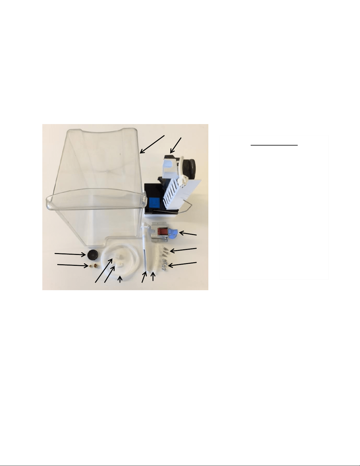
148
16.11.3: Ice Maker Kit
Model RF (without icemaker) can have an AGA Marvel factory authorized Icemaker kit installed.
The part number for the AGA Marvel ice maker kit is S42418151-CLR.
This kit can be obtained through the AGA Marvel order desk. Call 1-800-223-3900 and follow
the phone queue to the order department.
For installation the following tools will be required:
5/16” Nut Driver
¼” Nut Driver
½” Open End Wrench
5/8” Open End Wrench
Flat Blade Screwdriver
1
4
3
2
6
7
5
11
10
12
9
8
Kit Components
1) Ice Bucket
2) Ice Maker
3) Fill Valve
4) #8 x 5/8” HD SS Hex Screw
5) #10 x ½ AB Hex HD Screw
6) Tube Wrap
7) Fill Tube
8) ¼” Plastic Water Line
9) P-Clamp
10) Fill Tube Nut
11) Nut and Ferrule
12) Plug Bushing
13) Installation Instructions
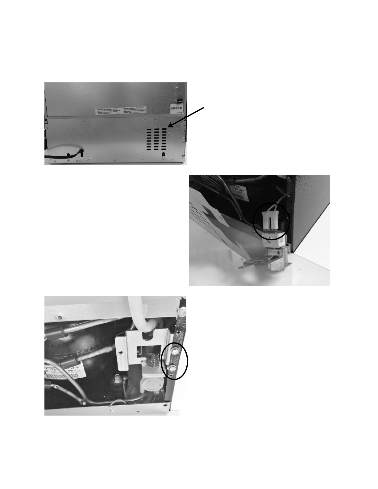
149
16.11.3.1: Ice Maker Kit Installation Instructions:
Follow specific instructions included in kit.
Remove rear panel to machine
compartment.
Connect wire harness inside of
machine compartment to water
valve.
Attach water valve to rear cabinet
flange. Replace cover to machine
compartment.

150
Remove access cover in top rear,
right hand corner. Remove insulation
under cover and keep for use later.
Insert fill tube; connect water line
and compression nut. Secure fill tube
with screws.
Water (fill) tube
Water line with compression fitting
Compression nut
P clamp
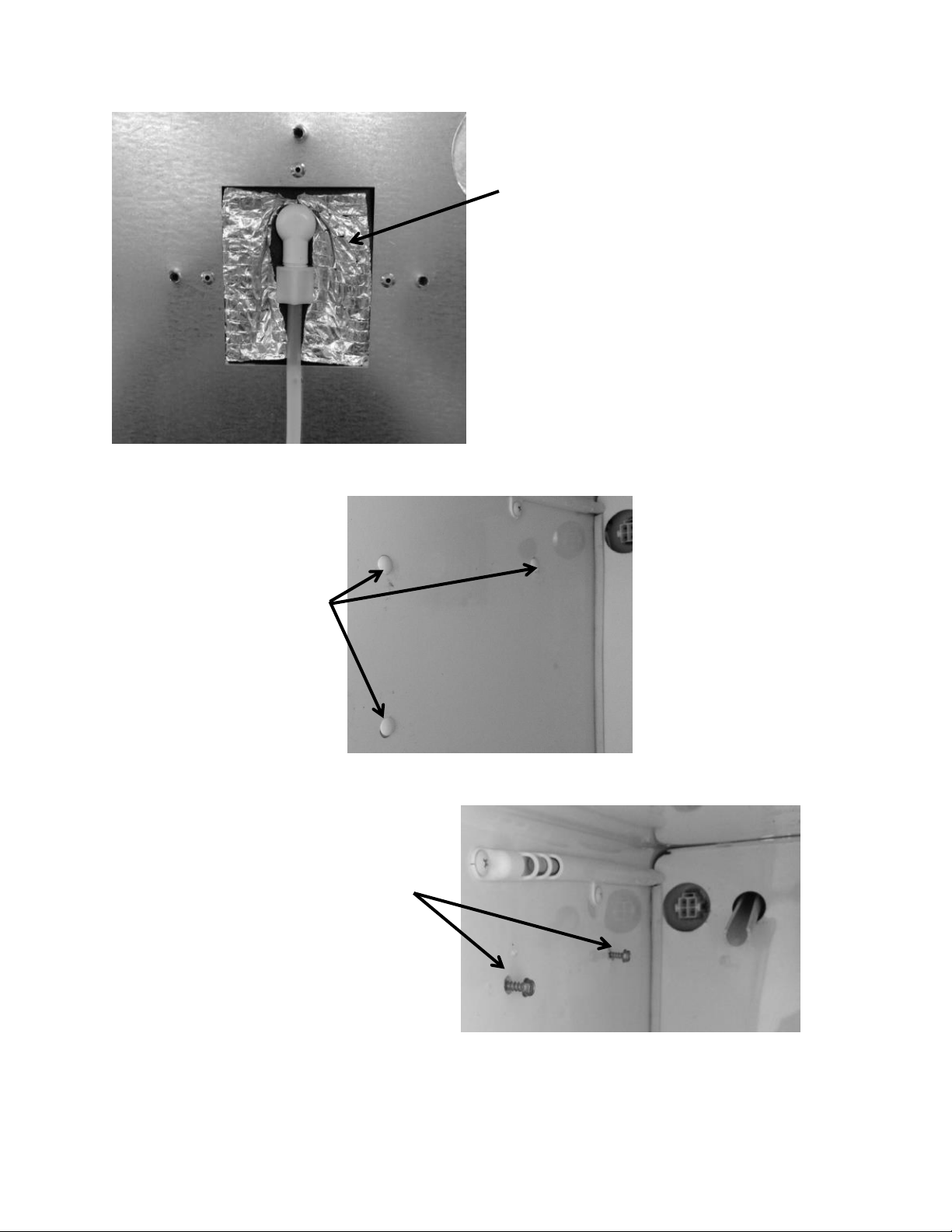
151
Replace insulation and access cover.
Remove three plastic screw
plugs on left hand side wall
in freezer compartment.
Install screws into the top two holes;
leave room to set the ice maker into
place on top of screws.
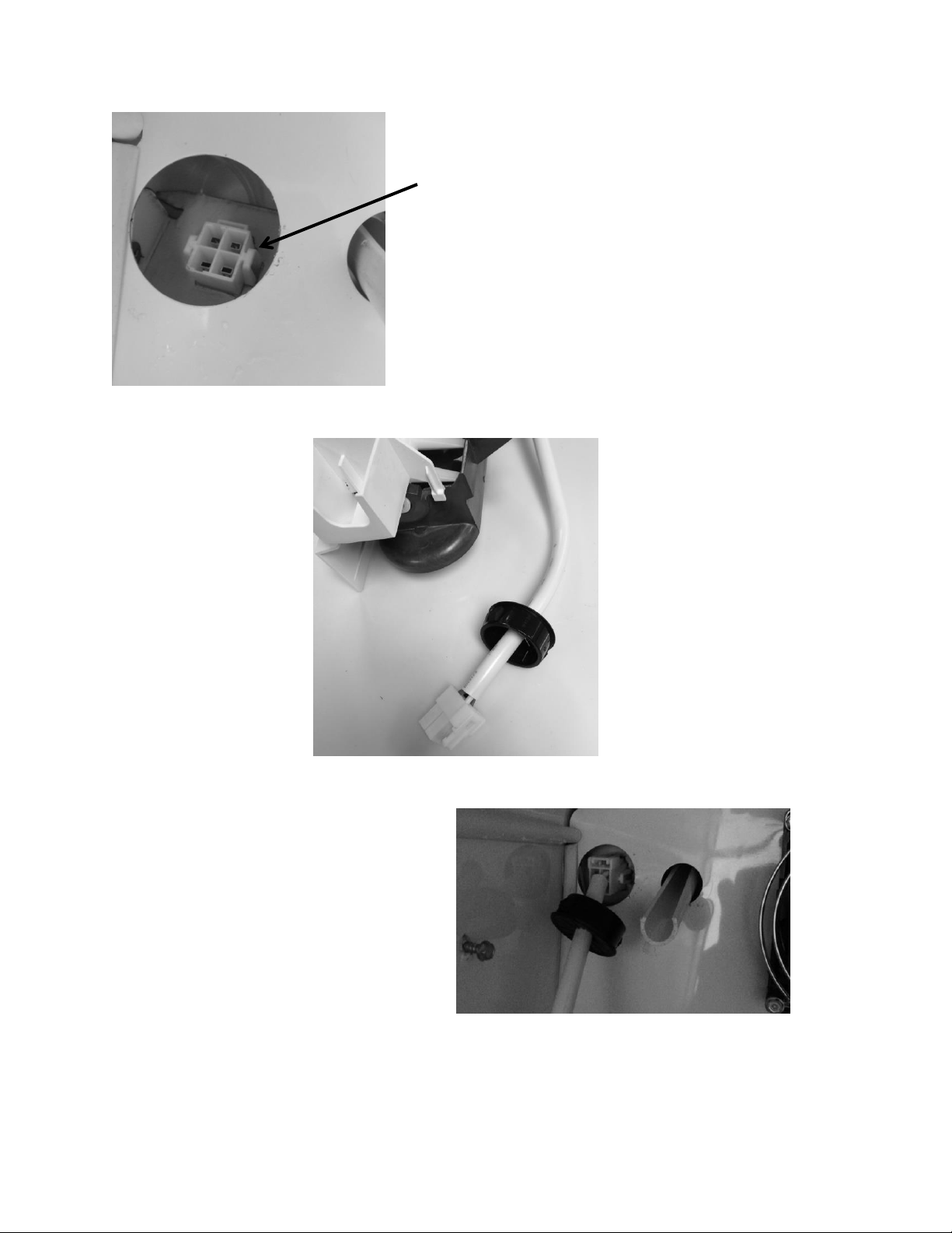
152
Place the plug bushing
over the ice maker wire
harness; smooth surface
facing outward.
Push and snap the wire connector
into place. Push the plug bushing
into the rear cover panel.
This photo shows the ice maker connection
located in the evaporator compartment.
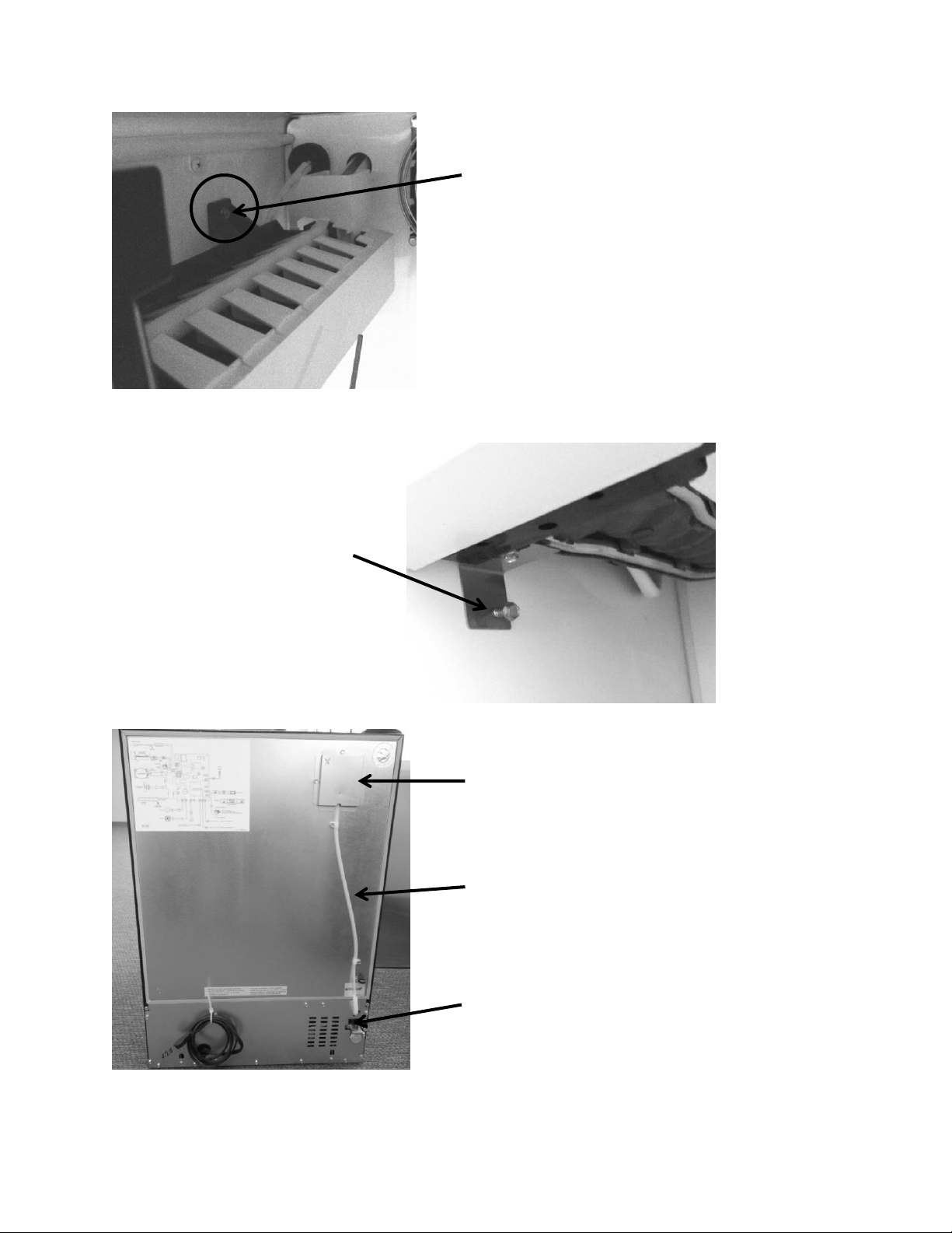
153
Set the Ice maker on top of
each of the (two) top
screws and tighten.
Install the bottom screw
into the bottom ice maker
bracket and tighten.
Access cover hiding the water fill tube
¼” nylon water line with P-clamps
Water valve
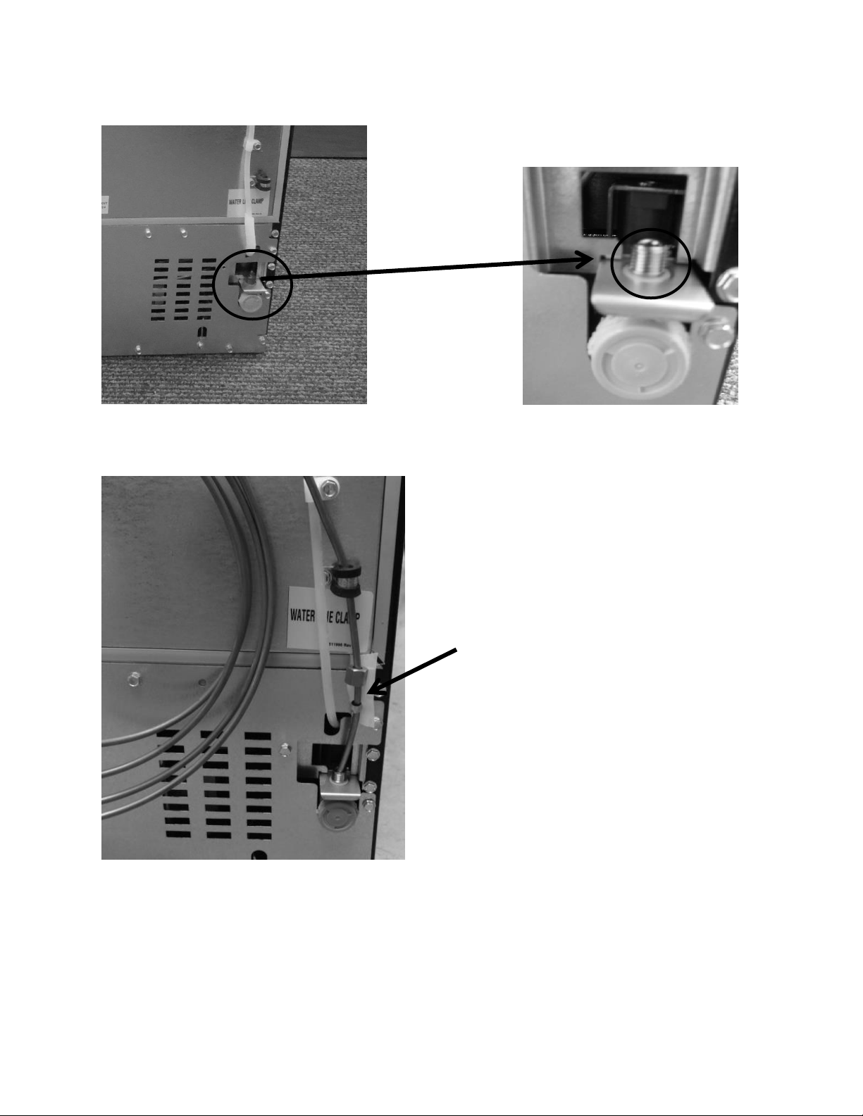
154
Install water supply line to the water
valve, seat coupling and tighten the
compression nut to the water valve.
Check for water leaks once supply water
is reconnected.
Supply water inlet: ¼” compression nut with coupling.
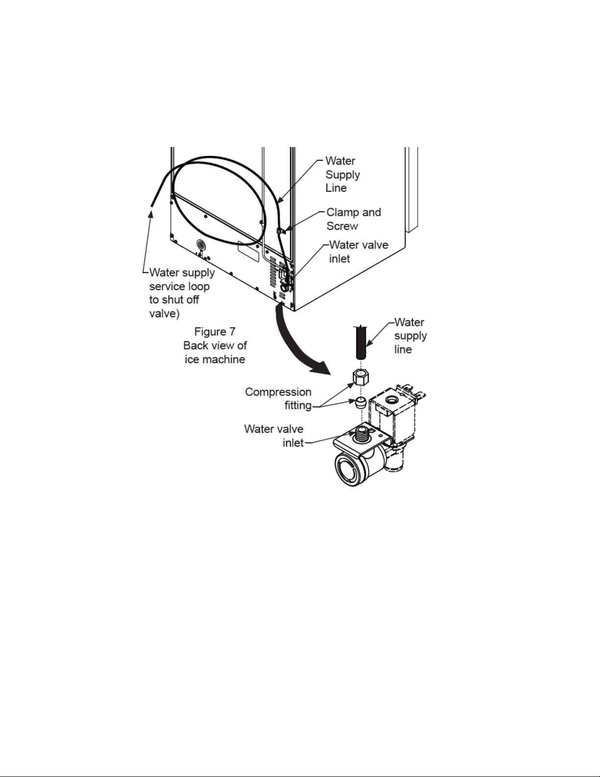
155
16.11.3.2: Installation Schematic
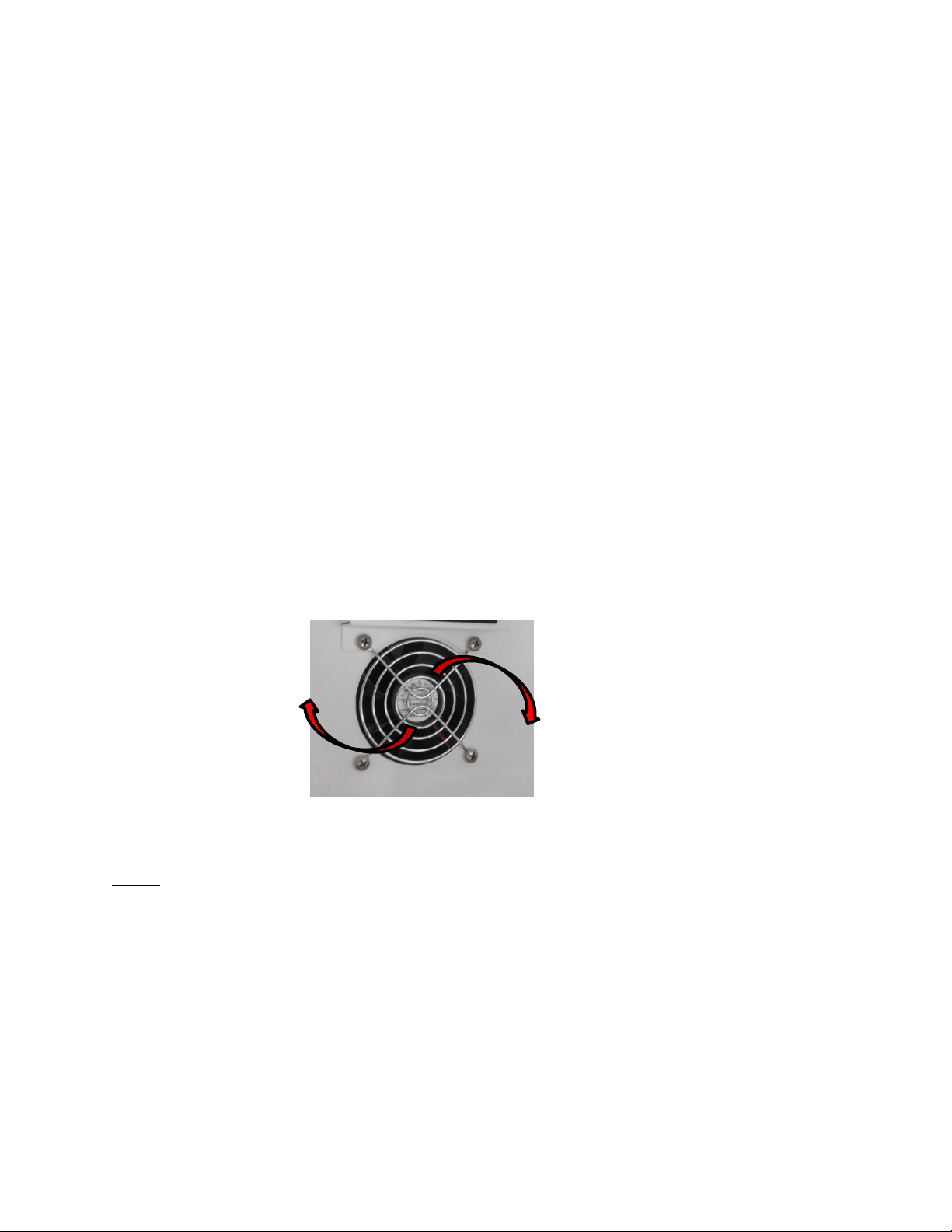
156
Section 17: Outdoor Models
17.1: Operation
Dynamic cooling utilizing a forced air condenser and interior circulation fans moves air
effectively and efficiently. The Prime control system brings the control interface display
inboard where it will not be affected by the elements of the outdoors. The main control
board is located in the machine compartment. It is shielded by a mylar curtain behind
the compartment access cover, this also protects from the elements of the outdoors.
The entire cabinet and door are wrapped with a stainless finish.
17.2: Characteristics / Differences
Outdoor appliances are typically identified by the stainless steel wrapped cabinet and
matching stainless door. The control is located in the interior of the appliance.
In addition, the rear access panel in the machine compartment has a mylar curtain
installed along the top edge to prevent water or moisture from entering.
17.3: Fans
Fan function and location is not unlike the indoor Marvel and Marvel Pro models. Air is
drawn across the evaporator plate from the supply louvers and outward into the interior
cabinet through the circulation fan. The blades rotate in a clockwise direction as you
face the hub.
NOTE: As of mid-August 2015, a rear fan guard was added to the fan assemblies on the
outdoor beverage center and beverage dispenser models. The fan guard is to eliminate the
possibility of wires getting caught in the fan blade from behind the coil cover.
The approximate serial number range is 20150824xxxH. This is an approximate date and some
variation may be seen in the field.
An exploded view on the following page shows the assembly drawing of the coil cover
components along with both the front and rear fan guards.
Evaporator Fan
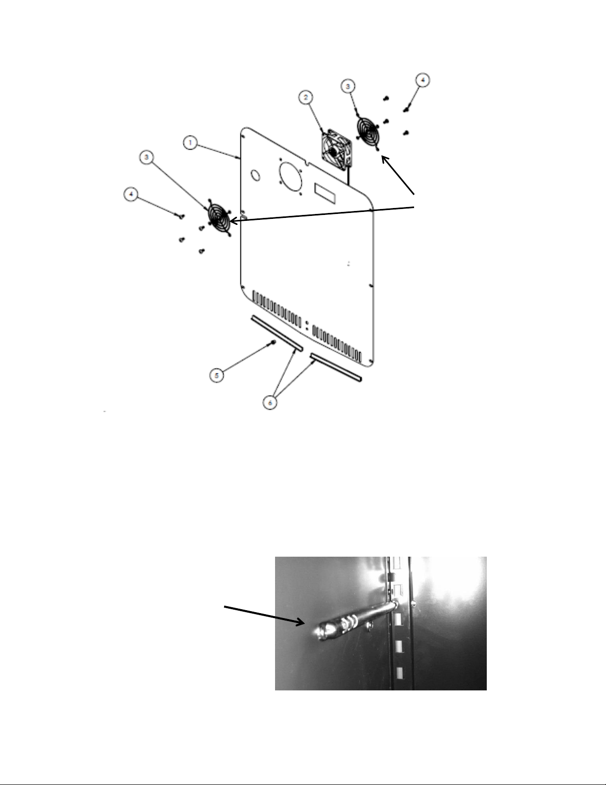
157
17.4: Thermistors
Thermistors are still NTC and located on the midway point of either the left or right
hand side of the cabinet liner. A defrost thermistor is also attached to the upper left
hand evaporator plate (Refer to Section 6).
Shielded Cabinet Air Thermistor
This exploded view drawing shows
the front and rear fan guard. As
mentioned on the previous page, the
additional rear fan guard was added
to outdoor beverage centers and
beverage dispensers to prevent wire
interference.
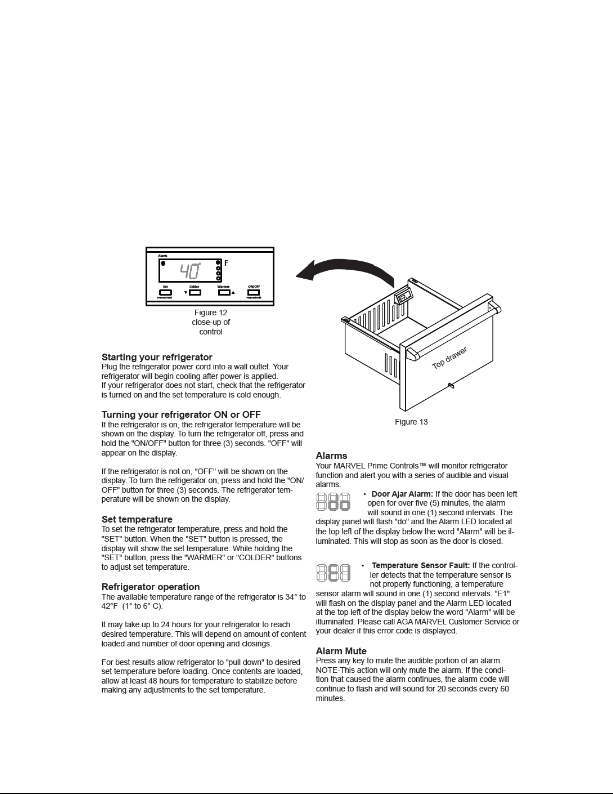
158
17.5: Control Type
The Prime control is used in all outdoor applications. It is the same basic control as the
previously used Micro Sentry controls; however the control is reduced considerably in
depth and appears identical to the control used in the previous door mounted versions
in the Marvel Scientific models.
17.6 : Control Functions
The following is an excerpt from the customer Owners Guide regarding
general control usage.
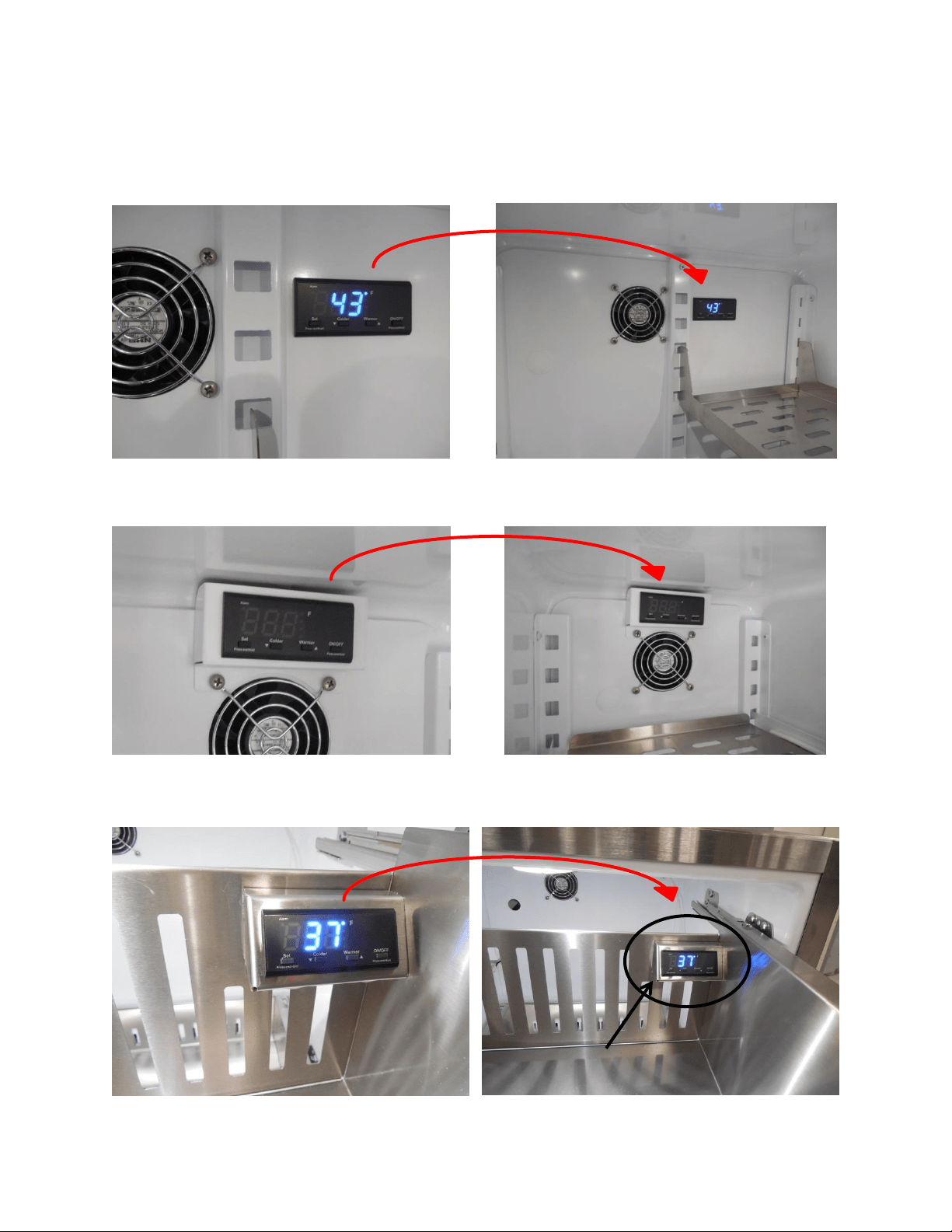
159
17.7: Control Locations per Model
17.7.1: Beverage Centers and Beverage Dispensers (6 cu. ft.)
17.7.2: Beverage Center (3 cu. ft.)
17.7.3: Refrigerator Drawer
Location: Upper Right Hand
corner of the top drawer.
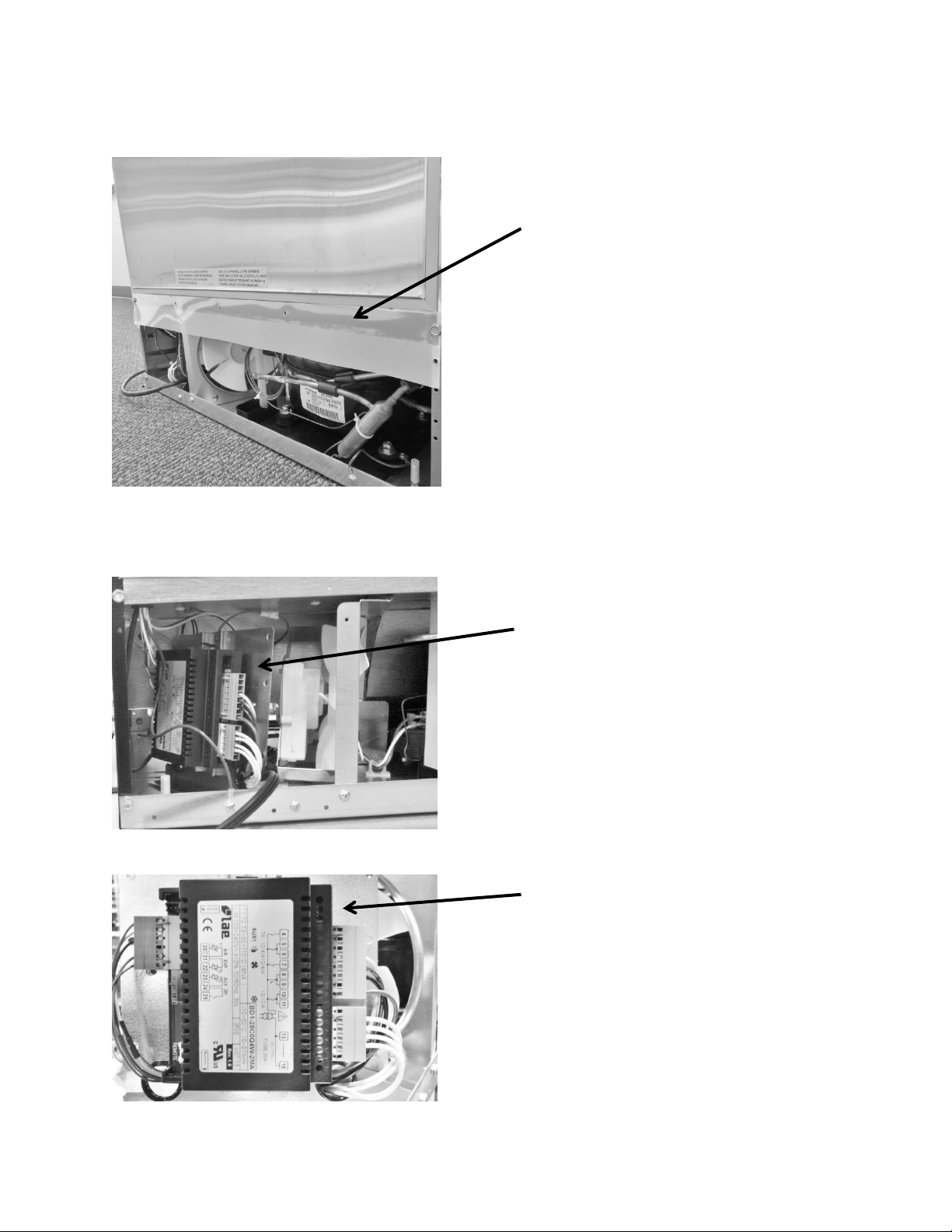
160
17.8: Machine Compartment
17.9: Main Power Board Access
Mylar rain curtain on all outdoor
under counter products.
The main power board location is
on the left hand side of the
machine compartment.
Visual of the main control board
attached to its mounting bracket
with all wire harnesses connected.
The basic machine compartment
and mechanical assembly is nearly
identical as discussed in Section 3,
seen earlier in this manual.
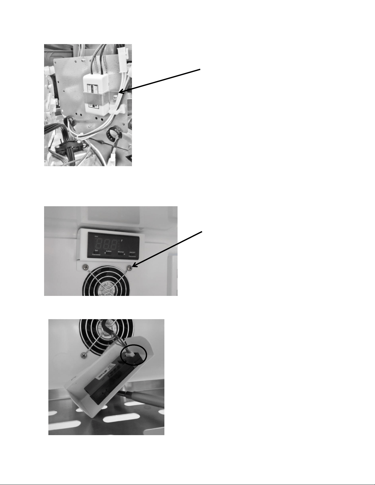
161
17.10: Display Access and Replacement
17.10.1: 3 Cubic Beverage Centers
12 VDC Power Supply – Serves the
evaporator fan. Located on rear side of
the main power board bracket.
To access the control, remove the
two screws on the bottom housing
flange. These screws also secure the
fan grill and motor to the evaporator
cover.
After removing the screws, grasp the control
and pull away from the evaporator cover.
To disconnect, press the release tab on the
side of the wire connector and remove the
communication cable.
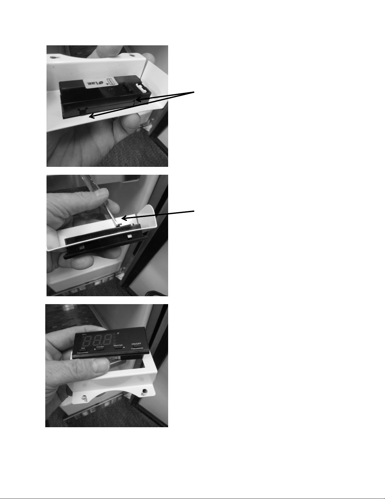
162
The control can be removed by depressing
the four locking tabs (2 on each side) on
the control body, with the end of a small
screw driver.
A small screw driver is used to release the
locking tabs on the control from the control
housing.
The control can now be removed through
the front of the housing.
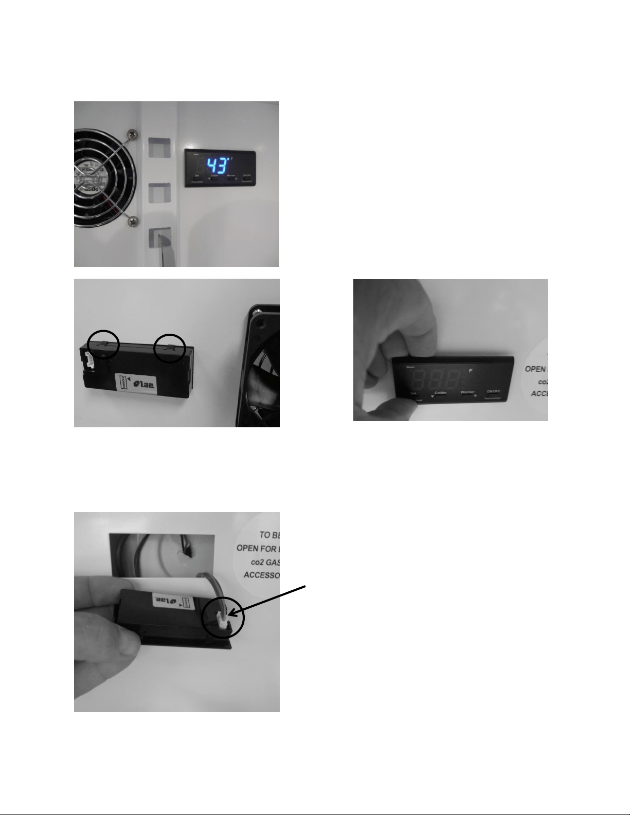
163
17.10.2: 6 Cubic Foot (Beverage Centers and Dispensers)
Rear view
Front view
To remove the control: Insert your fingers on the
top of the control and press downward. This will
release the two bottom tabs. Pull the top of the
control outward from the evaporator cover.
Tab release: Two tabs are located on the top
and two on the bottom on the control.
Disconnect the wire harness from the control
by pressing the release tab on the outside of
the connector.
Reverse the process above to re-install the control.
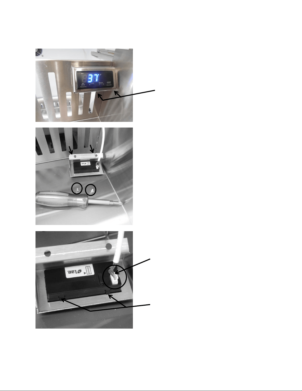
164
17.10.3: 6 Cubic Foot (Refrigerated Drawers)
On Refrigerated Drawers: Follow the
steps below. Two mounting screws
are located on the bottom flange of
the control housing.
To access the control, remove the two
screws on the bottom housing flange. Grasp
the control and pull away from the drawer.
To disconnect, press the release tab on the side
of the wire connector and remove the
communication cable.
Locking tabs, push to release.
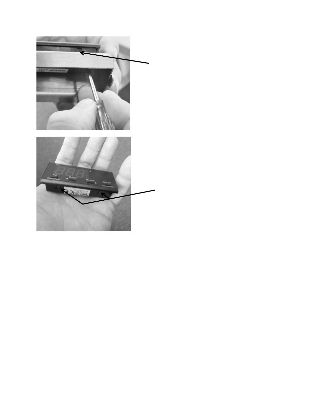
165
The control can be removed by depressing the
four locking tabs (2 on each side) of the control
body, with the end of a small screw driver. This
will allow the control to be removed from the
front of the housing.
Locking tabs, push to release.
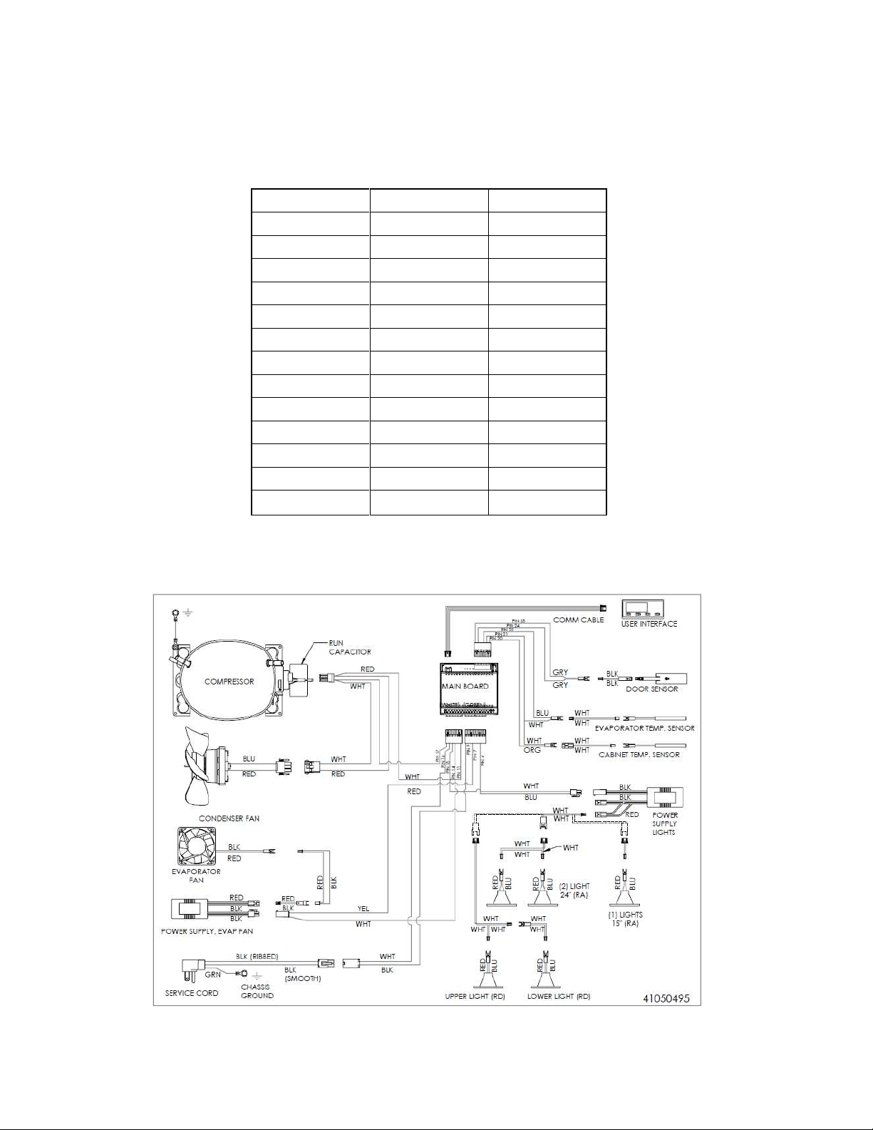
166
17.11: Thermistor Resistance
Temperatures are monitored individually by 10K @ 25°C NTC sensors.
This is a reduced version of the resistance chart seen in Section 6.4
°C
°F
K- Ohms
-15
5
5.365
-10
14
4.251
-5
23
3.389
0
32
2.722
5
41
2.202
10
50
1.793
15
59
1.467
20
68
1.208
25
77
1
30
86
0.8315
35
95
0.6948
40
104
0.5834
45
113
0.4917
17.12: Wiring Diagram
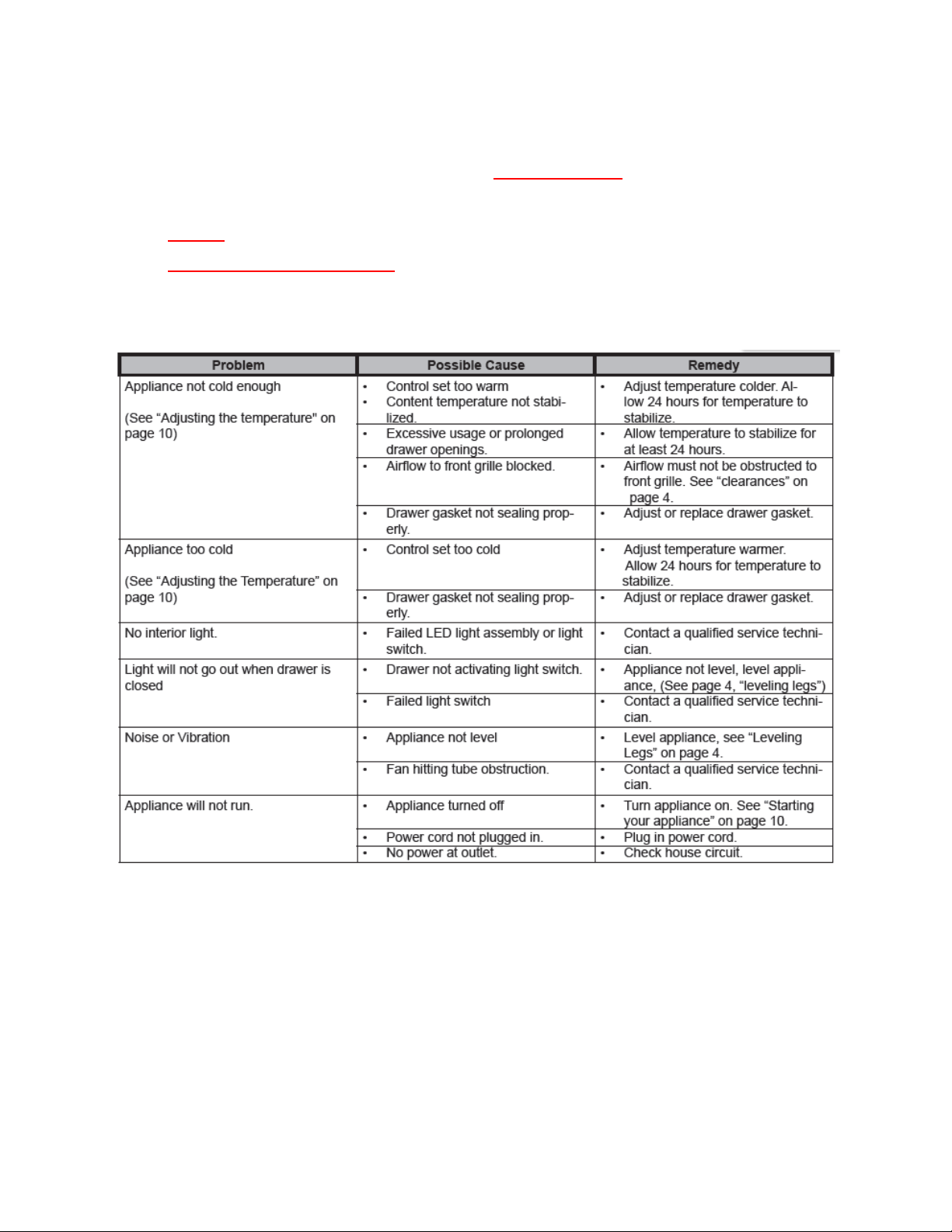
167
17.13: Generic Trouble shooting Charts
The following charts are offered for reference only and are not
comprehensive diagnostic charts.
NOTE: Any page numbers referenced on these charts are referring to the
Customers Owners Guide NOT this Service Manual.
17.13.1: Refrigerated Drawers
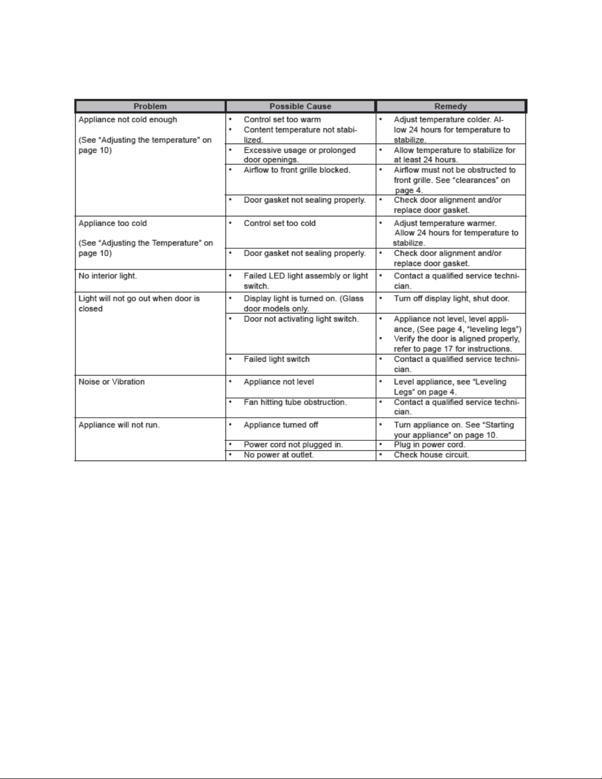
168
17.13.2: Beverage Centers
17.14: Refrigeration and Mechanical
The basic refrigeration and mechanical operation and assembly are not unlike that
discussed earlier in this manual. This information can be reviewed in Chapters 3 and 4.
The basic machine compartment and mechanical layout is nearly identical as
discussed in Section 3 seen earlier in this manual.
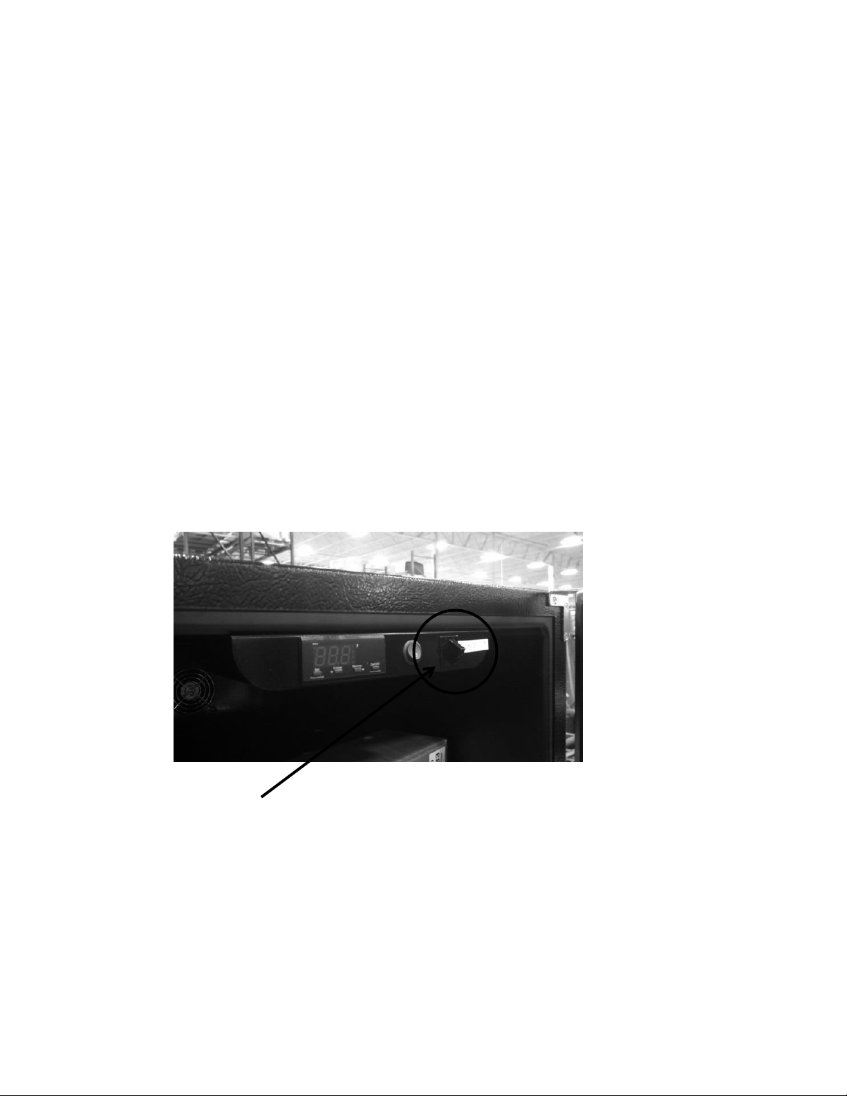
169
Section 18: Prime Control
18.1: Control Type
The prime control still utilizes the top mounted control housing as seen in the picture below.
It is the same basic control as the previously used Micro Sentry controls; however the control is
reduced considerably in depth and appears identical to the control used in the previous door
mounted versions in the Marvel Scientific models and the current Outdoor Models.
The control system is driven by a NTC thermistor, located on the mid cabinet sidewall and
defrosted by a similar thermistor attached to the upper left hand evaporator plate (Refer to
section 6).
The control housing assembly consists of the control, display light button, and the door
activated light rocker switch.
Excluding model options, the cabinet design, mechanical operation, and air flow are identical to
that mentioned in section 3 of this manual. The main difference seen between the Prime and
Aurora control systems is that of the control system itself. There is no variation cabinet and
defrost thermistor function between the two control model types.
Light Rocker Switch – Door activated
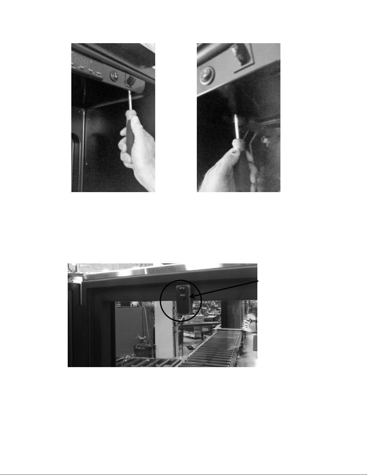
170
Rocker Switch Closer
Access the control housing by loosening the two recessed
screws in the front edge of the housing and one screw in
the rear flange of the housing. Slide the housing forward
and let it carefully drop away.
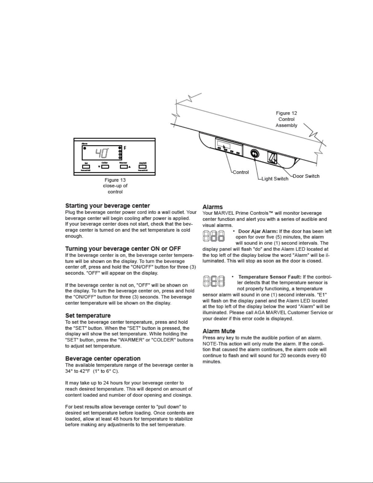
171
18.2: Control Functions
The following is an excerpt from the customer Owners Guide regarding general
control usage.
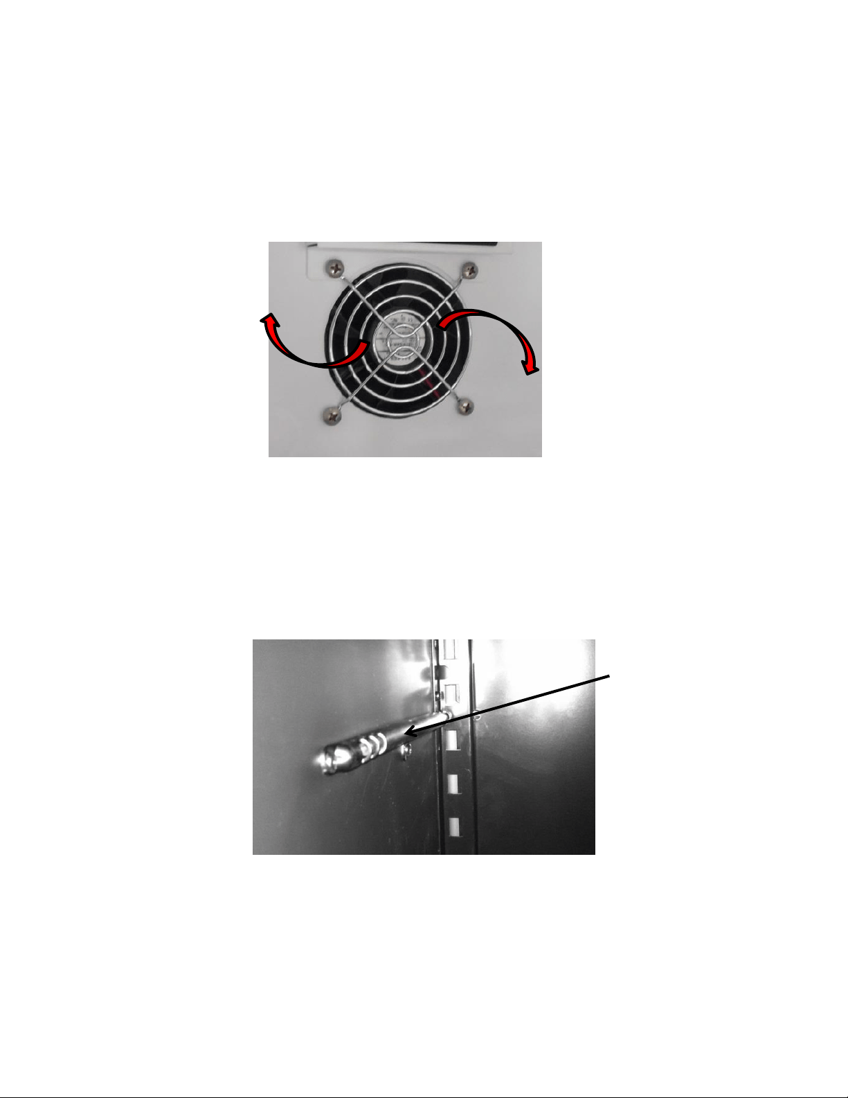
172
18.3: Fans
Fan function and location is not unlike the indoor Marvel and Marvel Pro models. Air is
drawn across the evaporator plate from the supply louvers and outward into the interior
cabinet through the circulation fan. The blades rotate in a clockwise direction as you
face the hub.
18.4: Thermistors
Thermistors are still NTC and located on the midway point of either the left or right
hand side of the cabinet liner. A defrost thermistor is also attached to the upper left
hand evaporator plate (Refer to section 6).
Shielded Cabinet
Air Thermistor
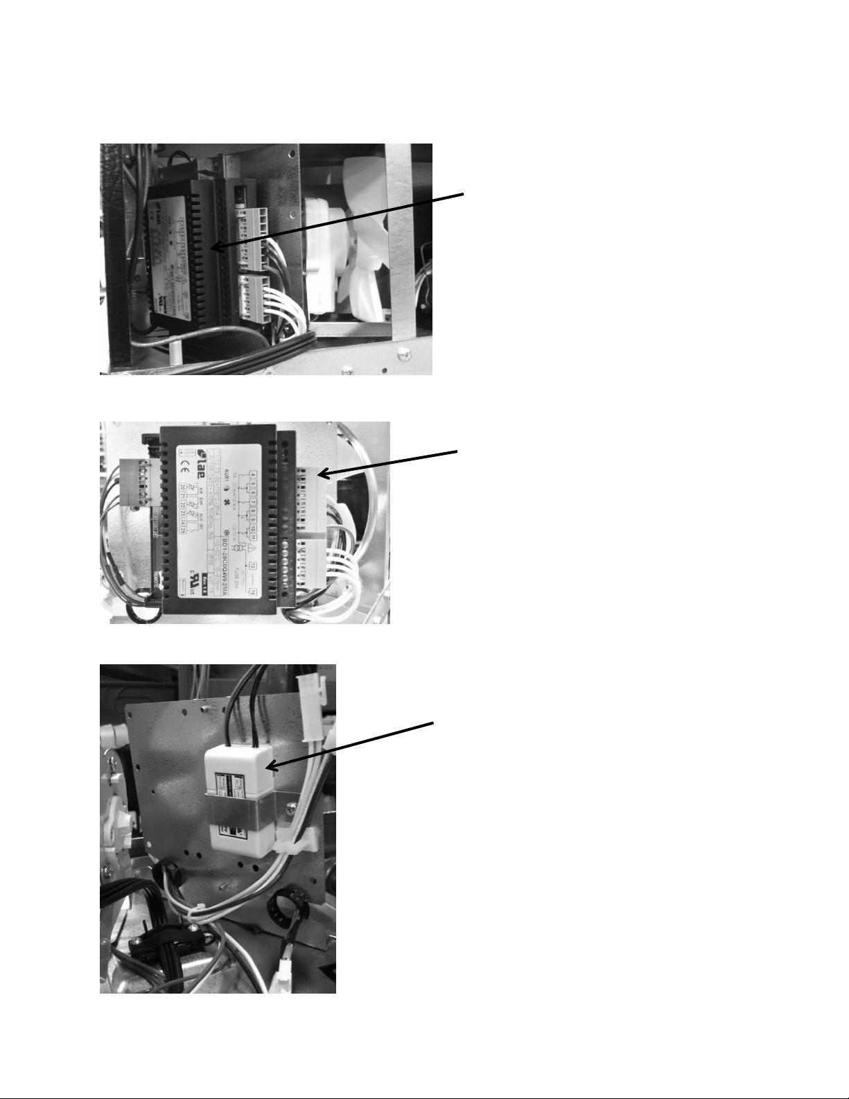
173
18.5: Machine Compartment
Main Power Board – Located
in the left hand side of
machine compartment.
12 VDC Power Supply – Serves the
evaporator fan. The power supply is
located on the rear side of the main
power board bracket.
Visual of the main control board
attached to its mounting bracket
with all wire harnesses connected.
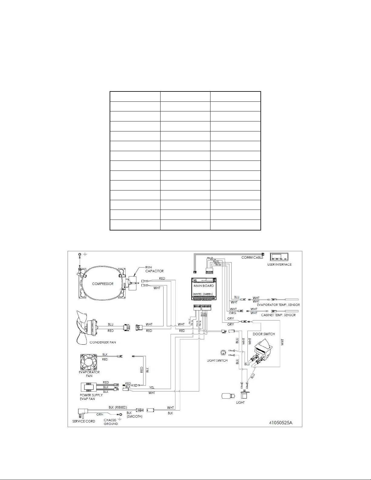
174
18.6: Thermistor Resistance
Temperatures are monitored individually by 10K @ 25°C NTC sensors.
This is a reduced version of the resistance chart seen in Section 6.4.
18.7: Wiring Diagram
°C
°F
K- Ohms
-15
5
5.365
-10
14
4.251
-5
23
3.389
0
32
2.722
5
41
2.202
10
50
1.793
15
59
1.467
20
68
1.208
25
77
1
30
86
0.8315
35
95
0.6948
40
104
0.5834
45
113
0.4917
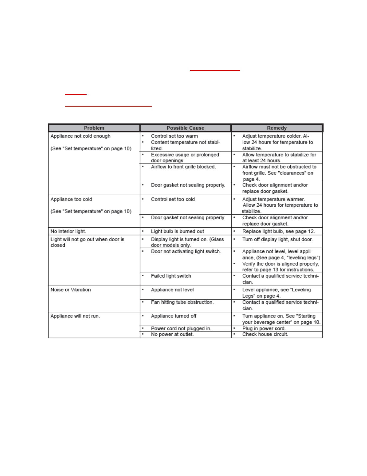
175
18.8: Generic Trouble shooting Chart
The following charts are offered for reference only and are not
comprehensive diagnostic charts.
NOTE: Any page numbers referenced on these charts are referring to the
Customers Owners Guide NOT this Service Manual.
18.9: Refrigeration and Mechanical
The basic refrigeration and mechanical operation and assembly are not unlike that
discussed earlier in this manual. This information can be reviewed in Chapters 3 and 4.
The basic machine compartment and mechanical assembly is nearly identical
as discussed in Section 3, seen earlier in this manual.
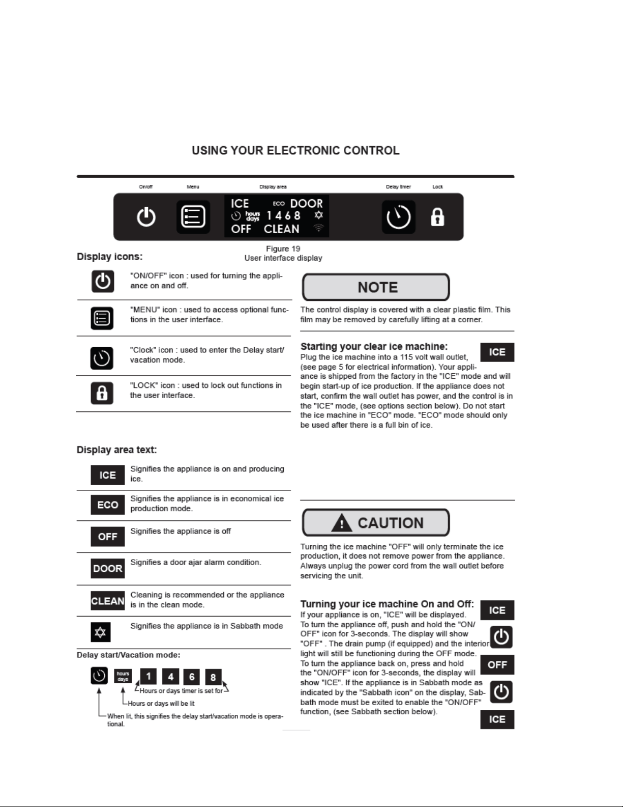
176
Section 19: Clear Ice Machines
19.1 Control Operation:
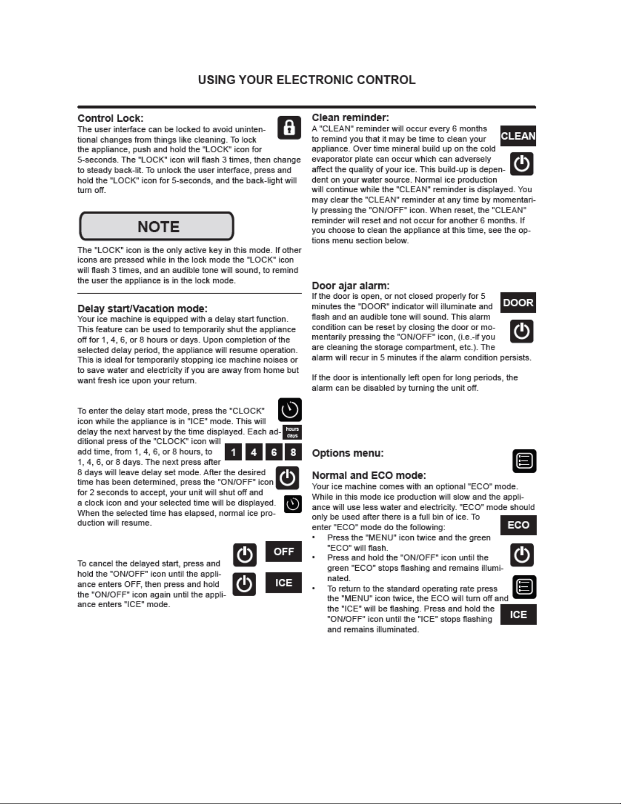
177
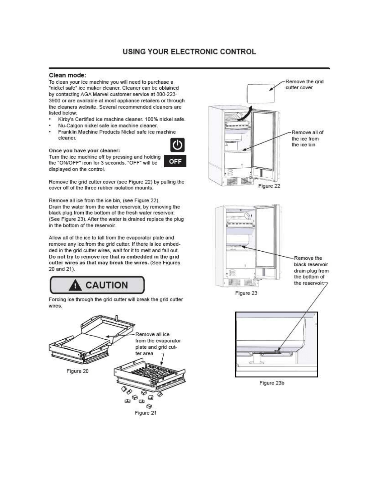
178
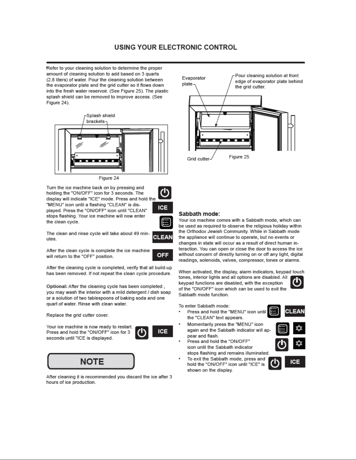
179
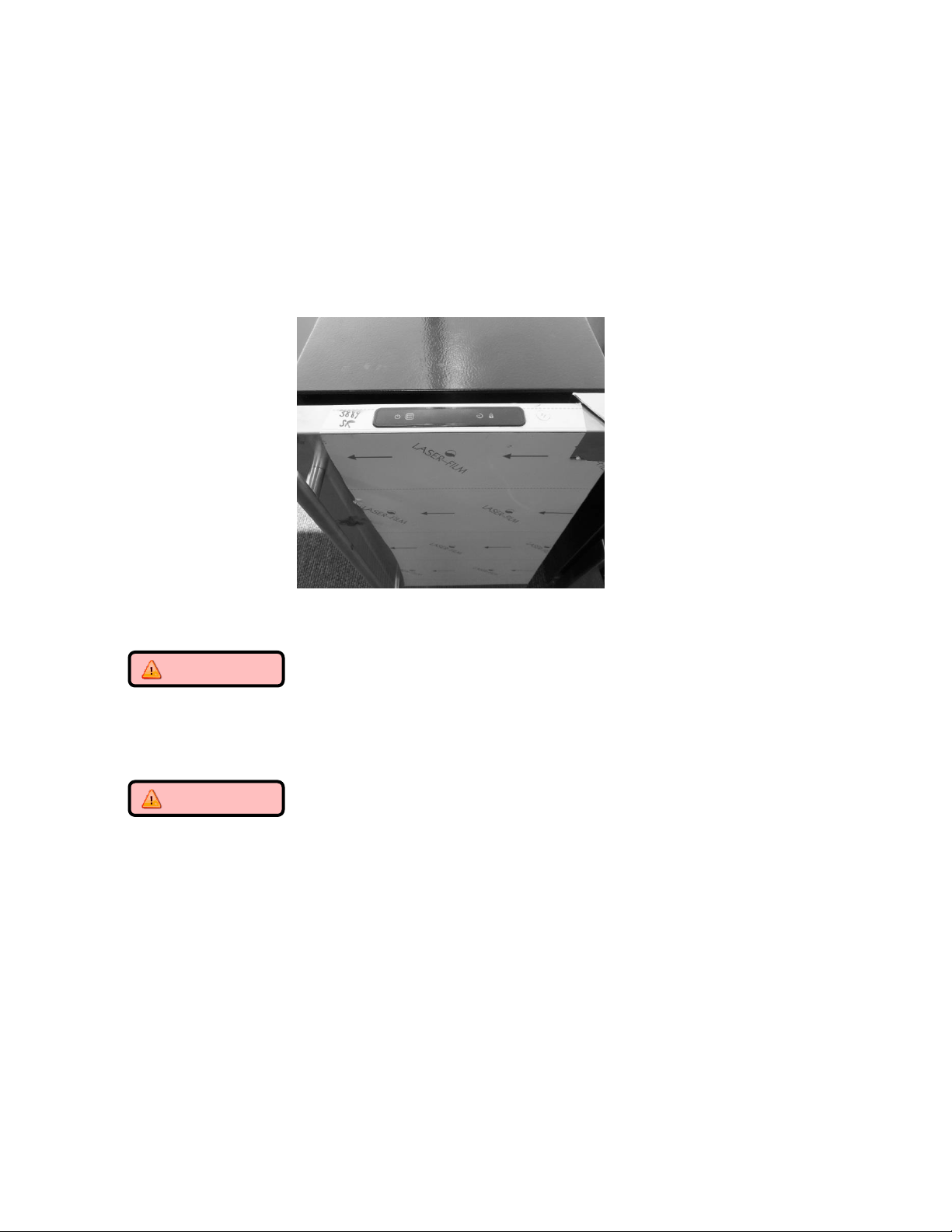
180
19.2: Control System
19.2.1 The User Interface:
The User Interface display is mounted to the door top and connected to the main power board
by means of a communication cable. The cable extends through the door and exits at the
bottom hinge location.
19.2.1.1 Removing the User Interface Display
CAUTION
It is recommended that a grounding strap be used when working with any
solid state control board application.
CAUTION
Care must be taken as a damaged wire or connector downstream from the
display disconnect connector cannot be repaired or replaced. The display
receiver and wiring harness are foamed in place. Any damage will result in a
door replacement.
1. Use the bottom edge of both thumb nails to gently pry up on the left hand side
of the display. (DO NOT use a sharp object such as a jack knife, putty knife, or
screwdriver. Objects like these can destroy the appearance of the display or
scratch the door).
2. Once the display is unseated, turn over and locate the display connector.
3. Using your thumb or forefinger to unsnap the lock.
4. Separate the connector and set the display aside.

181
User Interface PCA
Terminal
Description
J1
Com Cable to Main Board
J2
ICON / Key Switch
Lift user interface away from door receiver.
Release locking tab on display connector.
The user interface can now be removed.
Place finger nails under left hand lip of
user interface display.
Lift upwards.

182
19.2.1.2 Installing a new User Interface Display
1. Reverse the process used to remove the display board.
2. Carefully place the display back into the door receiver.
Apply a light downward pressure to the edge of the display to snap into place.
EXPLODED VIEW of User Interface Assembly
183
19.2.2 Main Control Board:
WARNING
Prior to removing the access cover to the machine compartment, disconnect the
supply voltage to the appliance. Failure to do this could result in an electrical
shock or possible death.
CAUTION
It is recommended that a grounding strap be used when working with any solid
state control board application.
19.2.2.1 Control Board Replacement
1. The main power board is located at the bottom, right hand, front corner of the machine
compartment.
2. To access the board, remove both the toe grill and access panel on the front of the
machine. To remove the access panel, the door should also be removed for
convenience.
3. The mullion bar separating the toe grill and the access panel should also be removed for
convenience.
4. Remove the 5/16” sheet metal screw that secures the control board in place.
5. Remove both large connectors on the bottom left hand side of the control board. Press
the release and pull each connector off its terminal.
6. The board can now be rotated into positon to disconnect the remaining electrical
connectors from the power board.
7. Once all wires are disconnected the board can then be maneuvered out of the
appliance.
8. The main board mounting bracket and the control housing are manufactured for a
positive fit upon installation.
a. The rear of the control bracket has two tabs to ensure a positive mounting
position.
b. The rear of the control housing has two accommodating slots to accept the
mounting tabs on the control board bracket.
c. Once the board is in position, it can be secured using the 5/16” sheet metal
screw.
9. Each wiring harness at the board is labeled as to its corresponding location on the
board. Prior to removing any harness, double check to insure that the identification on
each harness is legible for correct placement when repair in completed.
10. The control board terminals are also marked as to the correct harness locations.
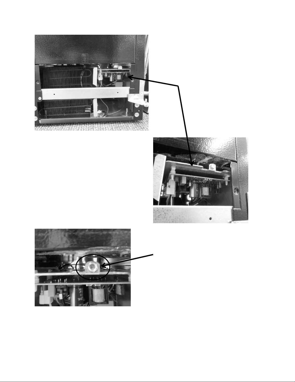
184
Remove screw holding
the control board
bracket in place.
Location of the main
power board.
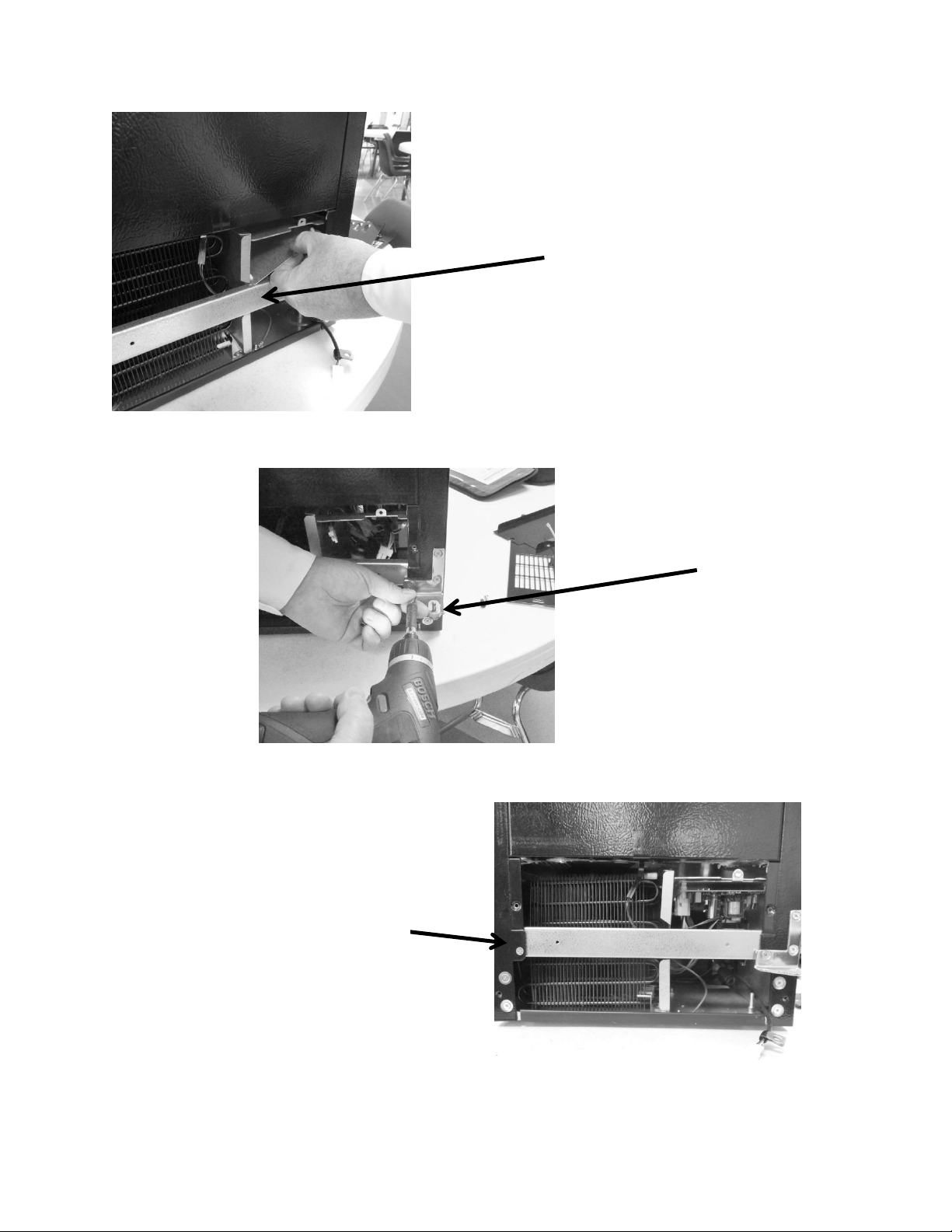
185
Center mullion
restricts ease of main
power board access.
Remove bottom left
hand screw from
lower hinge.
Remove single screw on
opposite end of mullion.
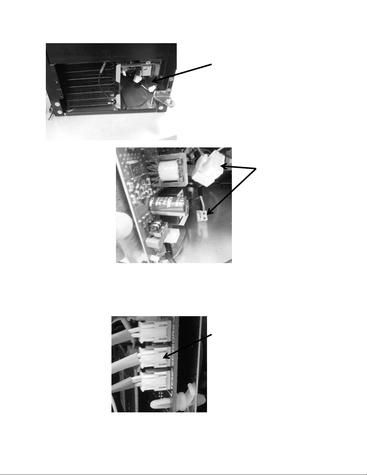
186
Tip board at a 90° angle and
disconnect the two large
white connectors from the
power board.
Mullion bar removed from
the cabinet.
Rotate the board as needed to disconnect the remaining cables from the
control board. All disconnects have a quick release tab on the connector.
Example: Clip release on side of
terminal disconnects. Press to
release. A click will be heard
when disengaged from control
board.
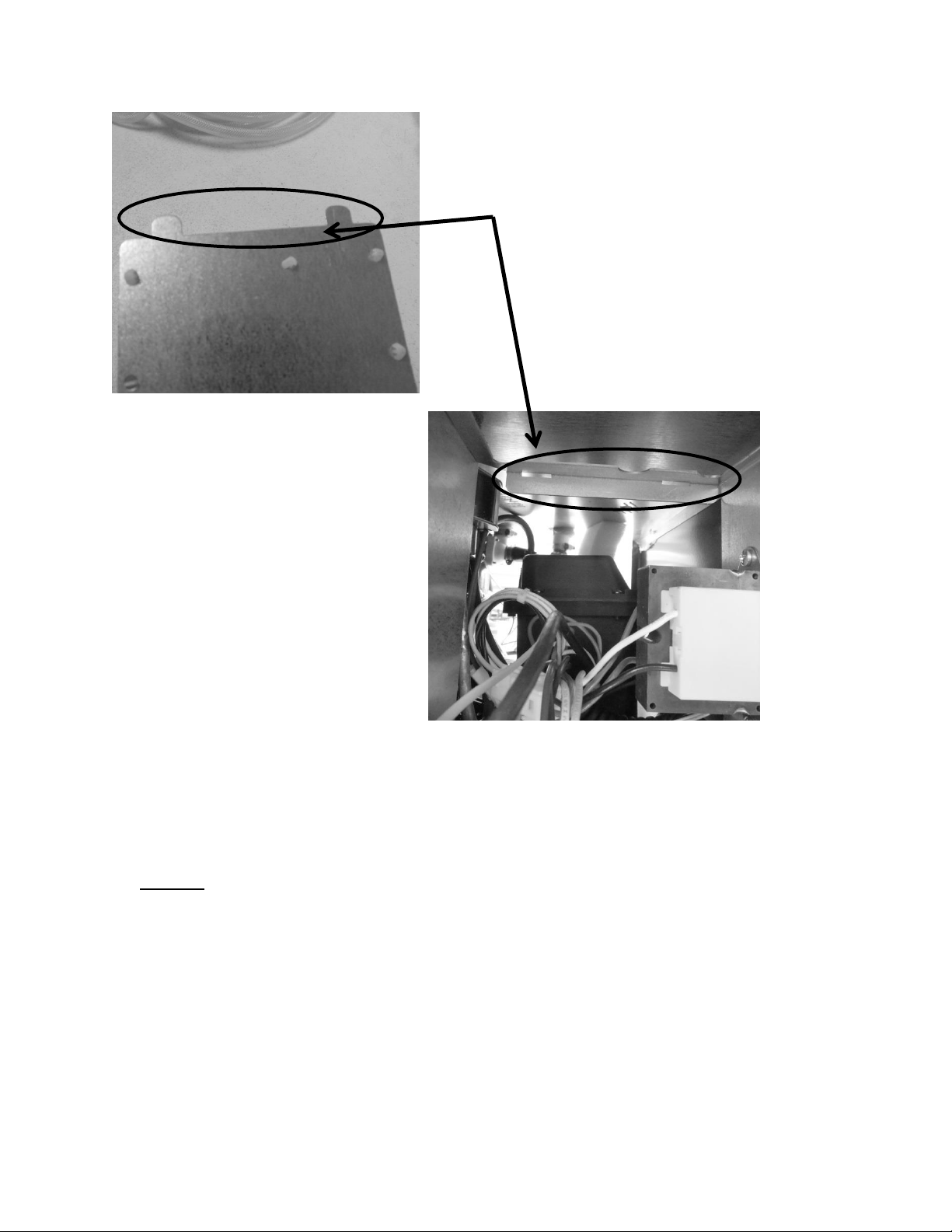
187
19.2.2.3 Control Board Terminal Identification
NOTE:
For wiring diagram and schematic, please refer to section 19.8.
The following pictures represent terminal identification on a single zone main power board.
These two photos show both the
mounting tabs on the bottom of the
main control board bracket and the
positioning slots on the adjoining
mounting bracket inside the machine
compartment.
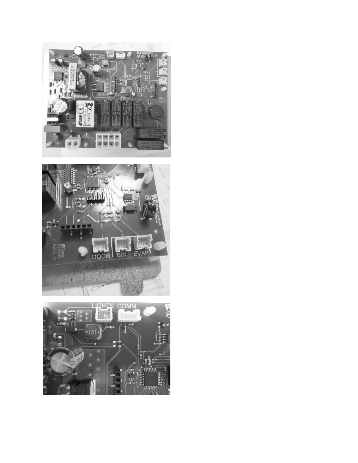
188
Connectors J6 & J7: (left to right): See wiring
diagram and schematic included in this section.
Connectors J3 – J5 (right to left): See wiring
diagram and schematic included in this section.
View of main power board. See wiring diagram
and schematic included in this section.
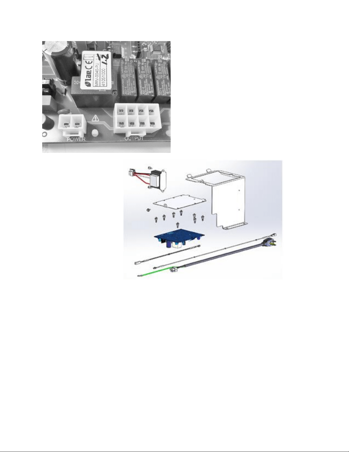
189
19.2.2.4 Control Board Installation
1. The main board mounting bracket and the control housing are manufactured for a
positive fit upon installation.
a. The rear of the control bracket has two tabs to ensure a positive mounting
position.
b. The rear of the control housing has two accommodating slots to accept the
mounting tabs on the control board bracket.
c. Once the board is in position, it can be secured using the 5/16” sheet metal
screw.
Connectors J1 and J7: See wiring diagram
and schematic included in section 19.8.
EXPLODED VIEW: Of
the control housing
assembly.
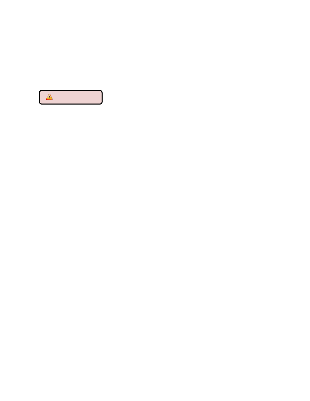
190
2. Replace all previously removed wiring connectors to the correct location on the main
board.
3. Prior to reinstalling the control board, verify that the slotted tabs on the rear of the
control mounting board glide into their adjoining locator slots on the control housing.
4. Slide the assembly into position and secure with the 5/16” sheet metal screw.
5. Replace the center mullion, lower access panel, toe grill, and door.
WARNING
Prior to removing the access cover to the machine compartment, disconnect the
supply voltage to the appliance. Failure to do this could result in an electrical
shock or possible death.
19.2.3 Thermistor (Sensor):
Thermistors can be checked by use of a multi-meter with the ability to read resistance. Refer to
the resistance chart on page 191.
19.2.3.1 Bin Thermistor
The bin thermistor senses the interior temperature allowing the control to adjust and properly
display the interior temperature. The thermistor is located at the mid, left hand wall. The
thermistor is covered with a plastic shield to prevent accidental damage.
The bin thermistor looks to “Start” a production mode at 43°F and to “Stop” ice production at
37°F.
19.2.3.2 System Thermistor
The high side (System) thermistor senses the system temperature at the filter drier inlet (liquid
line). Higher temperature variations will have a negative effect on ice production. Possible
effects could be caused by a higher ambient temperature or possibly a condenser air
restriction.
To account for these changes, the main control board is programmed to compensate by either
adding or subtracting a factor to the compressor “On Time” for every 1°F change the system
thermistor senses in temperature change. This adjustment will ensure that the ice maker
continues to produce a suitable amount of ice.
19.2.3.3 Checking Thermistors
The bin and high side thermistor harnesses from the control board are foamed in place. The
recommended method to ohm the thermistor is to remove the thermistor connector at the
control board and take the reading.
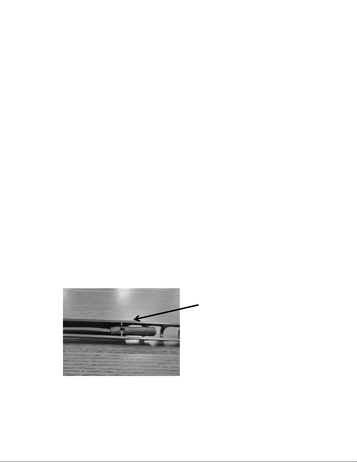
191
19.2.3.4 Removing the Bin Thermistor
1. Remove both the upper and lower access covers on the rear of the ice machine.
2. The base assembly can be slid out 8-10” to help this conversion. (See Section 5 for
guidance).
3. Remove the permagum and foam insulation out of the rear bun hole where the
thermistor is routed inside to out.
4. Disconnect the bad thermistor at the main power board connector plug.
5. Remove the two screws holding the bin thermistor shield.
6. Remove the thermistor bulb from the shield.
7. Remove the following components:
Escutcheon cover
Ice deflector
Grid cutter
And if necessary, the water reservoir
8. Remove the old thermistor cable.
19.2.3.5 Installing the Bin Thermistor
1. Carefully route the new thermistor cable and ensure that there is enough length to
connect thermistor at termination points on each end.
2. Repack the bun hole with the insulation products removed previously.
3. Carefully install all components removed in step 7 above.
4. Place the new thermistor into its protective shield. The underneath side of the shield is
fitted to accommodate the grooves on the thermistor bulb. Reattach to the bin sidewall.
5. Connect the thermistor to the appropriate spot on the main power board.
6. Reassemble the remaining mechanical section to the main cabinet and secure rear
access covers.
Bin Thermistor: NOTE the locator slot
inside the thermistor shield. The
grooved thermistor bulb fits firmly in
place inside the shield.
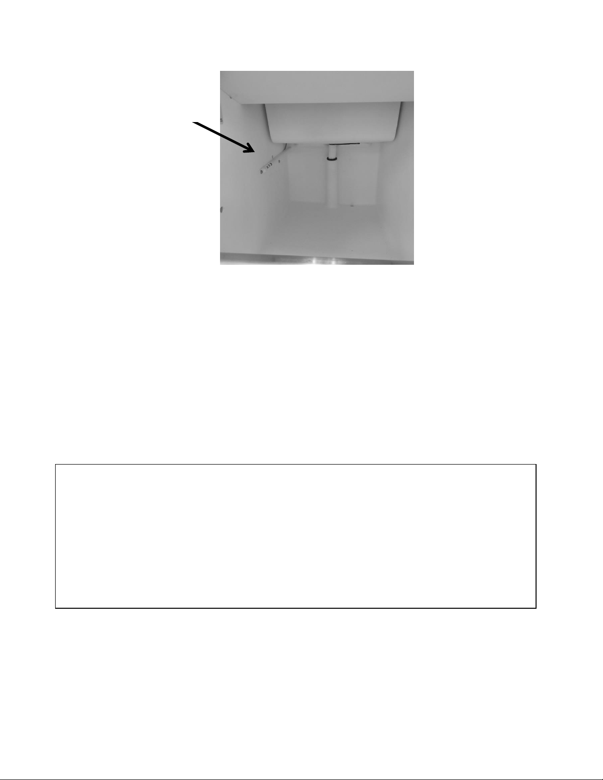
192
19.2.3.6 Removing the High Side Thermistor
1. The base assembly can be slid out 8-10” to help this conversion. (see section 5 for
guidance). Remove both the upper and lower access covers on the rear of the ice
machine to gain access.
2. Locate the thermistor connected to the liquid line at the filter drier inlet.
3. Cut the nylon zip tie holding the thermistor to the evaporator plate.
4. Disconnect the bad thermistor at the main power board connector plug and remove.
19.2.3.7 Installing the High Side Thermistor
1. Attach the new thermistor onto the same liquid line position (filter/drier) and firmly
secure with the zip tie.
At the time of this publication, the bin thermistor is a one piece assembly. Replacing the
thermistor will require removing the upper and lower rear panels, the interior escutcheon
panel, deflector panel, grid cutter, and the water reservoir.
Care in routing the thermistor wire is a concern to ensure that proper wire length is needed to
make the connection on the main power board.
DO NOT pull on the thermistor wire, this could cause damage to the replacement thermistor.
Bin sensor
location.
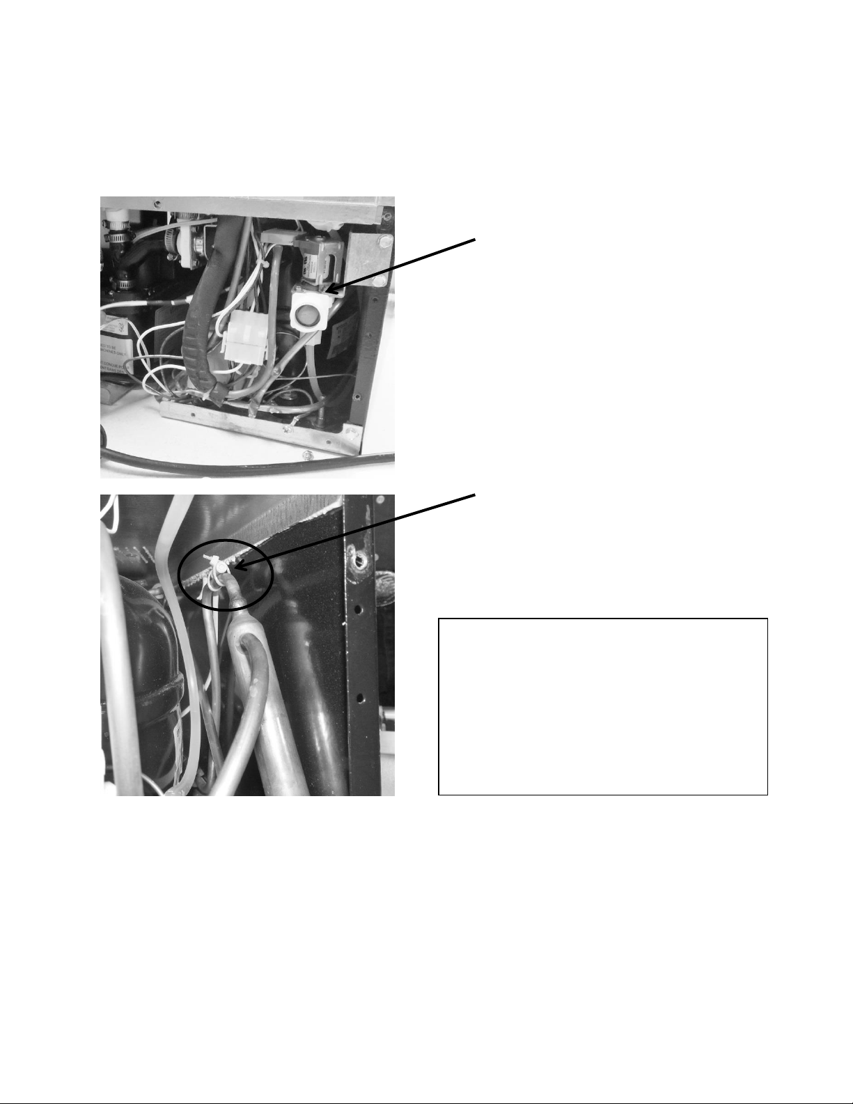
193
2. Feed the thermistor through the machine compartment and attach the connector to
the corresponding terminal on the main power board.
3. Reassemble the base and access covers in reverse order as they were removed.
19.2.3.8 Thermistor Harness Identification
1. Bin sensor, (orange) labeled: “Low Temp”
2. High side sensor, (red) labeled: “Defrost Evap.”
High side thermistor location: The
thermistor is fastened to the liquid
line at the filter drier with a nylon
wire tie.
High side thermistor location: The thermistor
is located on top of the filter drier inlet
(located behind the fill valve). The water valve
will have to be removed for access.
At the time of this publication; the
thermistor is a one piece assembly.
Replacing the thermistor will require
rerouting the thermistor wire to the
main control board in the machine
compartment.
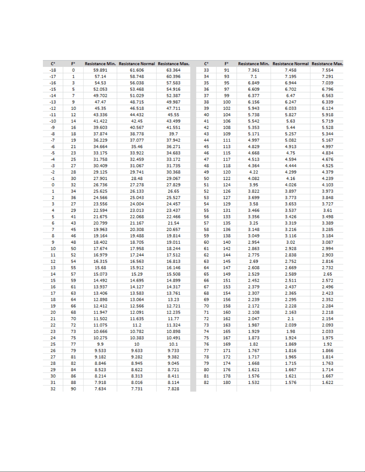
194
19.2.4 Temperature Resistance Chart:
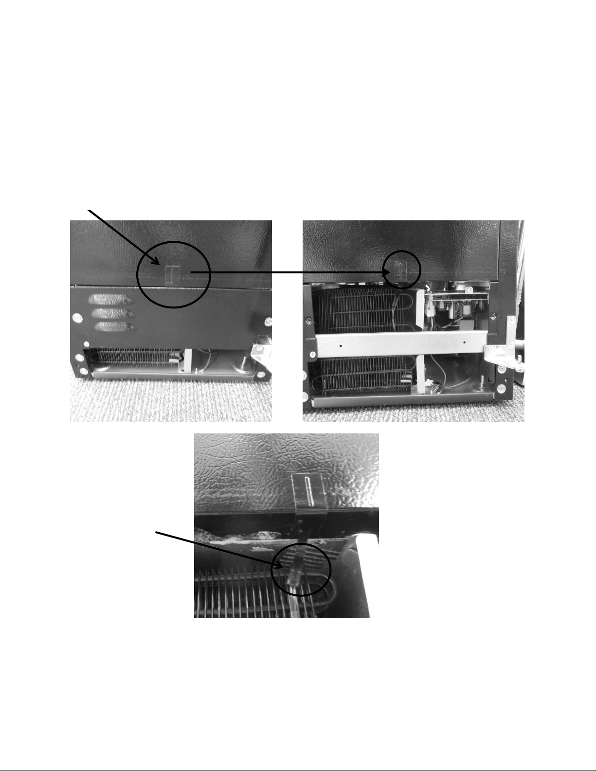
195
19.2.5 Door Sensor:
The door sensor is located on the bottom cabinet flange; approximately one third of the
distance away from the handle side of the cabinet.
The door sensor is resistance activated by the pressure of the door gasket. Light functionality
and the door alarm are directly related to this switch.
Door sensor location.
Sensor disconnect
terminal.
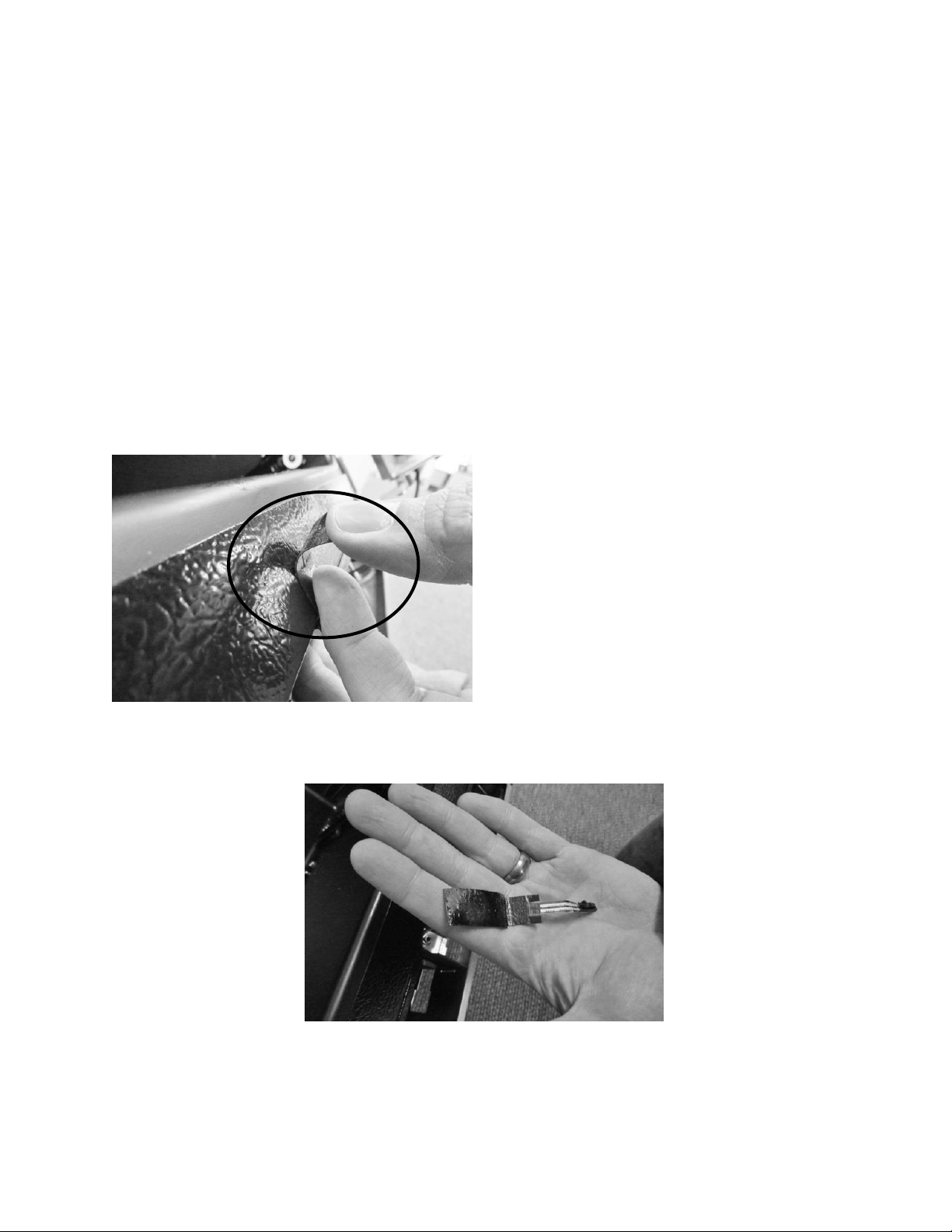
196
19.2.5.1 Door Sensor Removal
1. Remove the toe grill.
2. Disconnect the door sensor at the harness terminal behind the trim piece. See photo.
3. Remove the door sensor from the cabinet by starting in one of the upper corners and
peeling in a downward motion.
4. Once the sensor has been removed from the flange area:
a. Grasp the sensor with the right hand using the thumb and forefinger.
b. Grasp the electrical strip portion of the sensor between the thumb and
forefinger on the right hand.
5. Slowly work the sensor through the gap on the lower trim section to remove. The
upper portion of the electrical strip has some adhesive backing so care is advised.
Peel away from cabinet flange.
Sensor removed.

197
19.2.5.2 Door Sensor Replacement
1. Do not remove the adhesive backing from sensor until it is in place.
2. Slide the new sensor into the gap between the bottom flange and trim piece.
3. Once the sensor is in place:
a. Remove the adhesive backer from sensor.
b. Ensure the sensor is in position and carefully adhere to the cabinet. Apply
carefully using thumb pressure to the outer perimeter of the door sensor.
c. NOTE: Care should be taken not to apply unnecessary pressure directly on the
raised vertical center of the sensor face. The switch is pressure sensitive; any
undue pressure could damage the sensor.
19.2.6 Error Codes:
Thermistor (Sensor) Error Detection
Temperature thermistors are monitored continuously by the main power board. Any “OPEN,
SHORTED, or OUT of RANGE” thermistor circuit will initiate an alarm.
If an error is detected, the ice machine will immediately shut down and the display interface
will flash the corresponding fault code continuously. No audible alarm will sound.
Communication Error
Loss of communication between the main power board and the user interface will result in
either a continually flashing “ON” or “OFF” on the display.
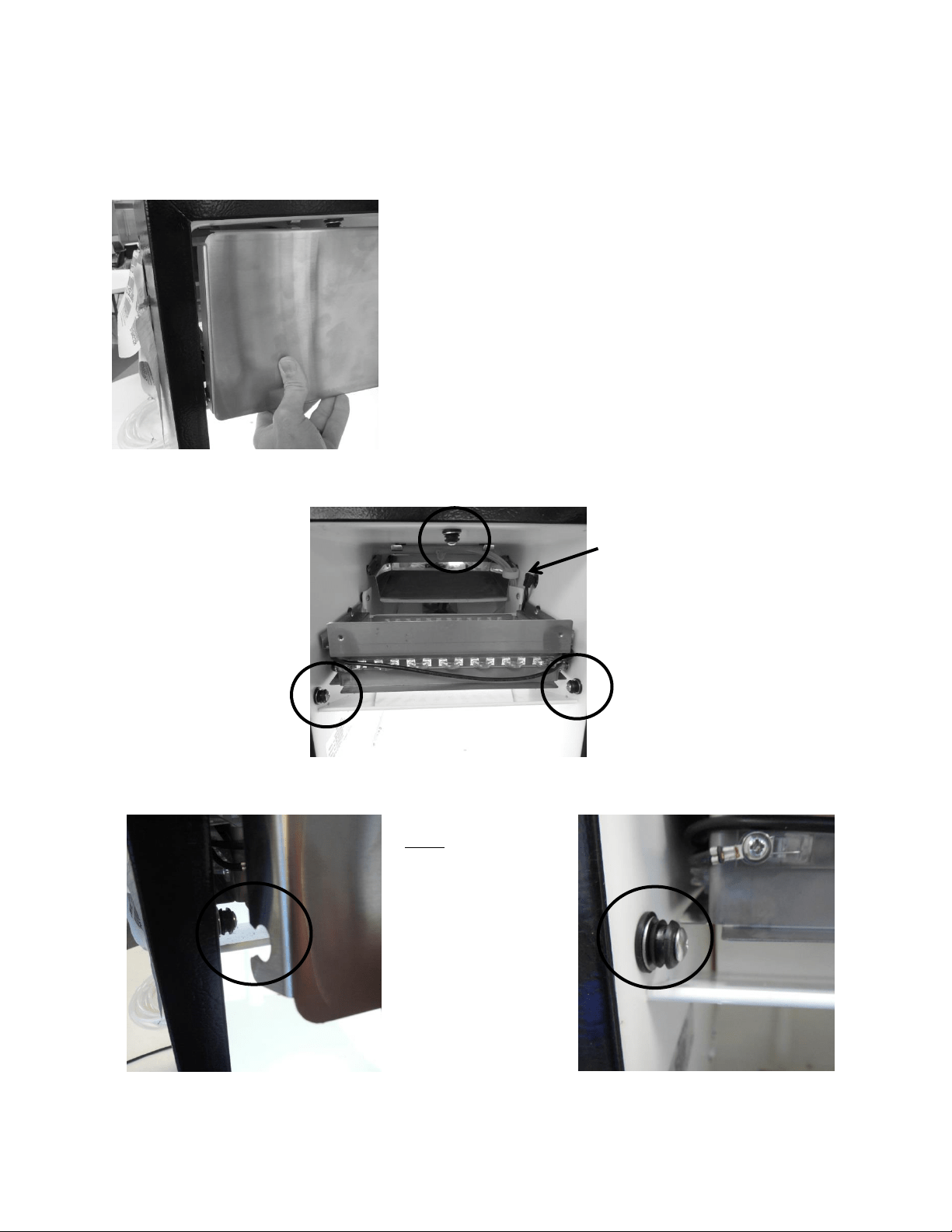
198
19.3: Interior Features
19.3.1 Escutcheon Cover:
Escutcheon mounting pegs (3)
To Remove the Cover: Grasp the bottom of
the cover with both hands and pull outward.
To Replace the Cover: Align the top of the cover to the
top center mounting peg. Lightly tap with the side of
your fist, or push firmly into place. The sides of the
cover can now be pushed into place.
Note: The notched
escutcheon cover and
rubber mounting
pegs.
The cover will be
secured, once placed
and pushed over the
rubber mounting
pegs.
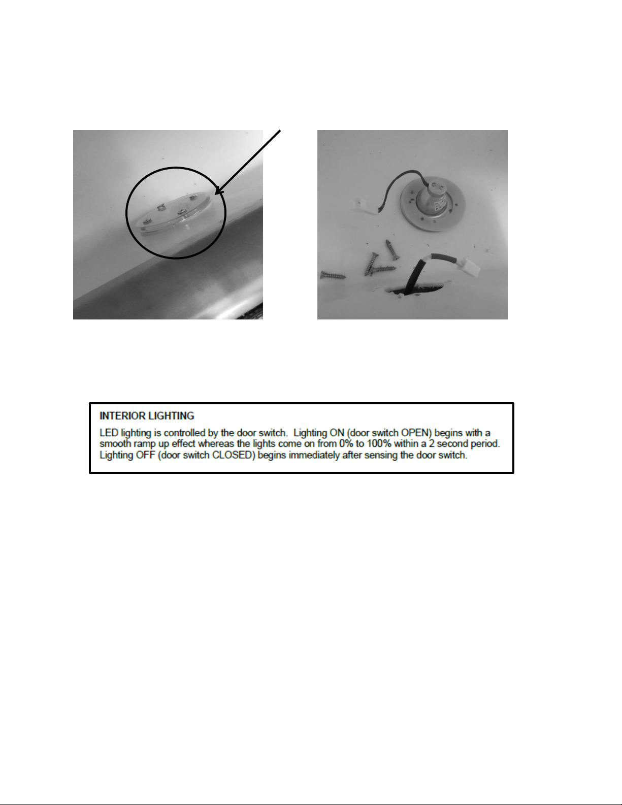
199
19.3.2 LED Lighting:
One LED light is located on the front side of the lower bin.
The LED lighting is controlled by the door switch mounted on the bottom flange of the cabinet.
Pressure from the door gasket makes and breaks the door switch circuitry to control light
function with door openings and closings.
Additional lighting features can be reviewed in the controls operation section in this manual.
19.3.2.1 Replacing the LED Light
1. Remove both Phillips screws in lens cover; the LED assembly can now be removed.
2. Disconnect the connector plug to replace LED.
3. Reverse process to install.
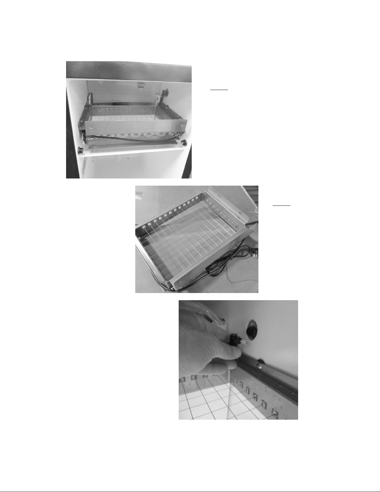
200
19.3.3 Grid Cutter:
The grid cutter installed.
NOTE: the water deflection
shield over the rear and the ice
deflector installed below the
grid cutter.
The grid cutter removed:
NOTE: Care must be taken
when handling the grid
cutter. One broken wire
will disable the entire grid.
To enable the grid cutter the
grounded power plug needs
to be connected at the
receptacle located on the mid
side wall of the machine
above the grid.
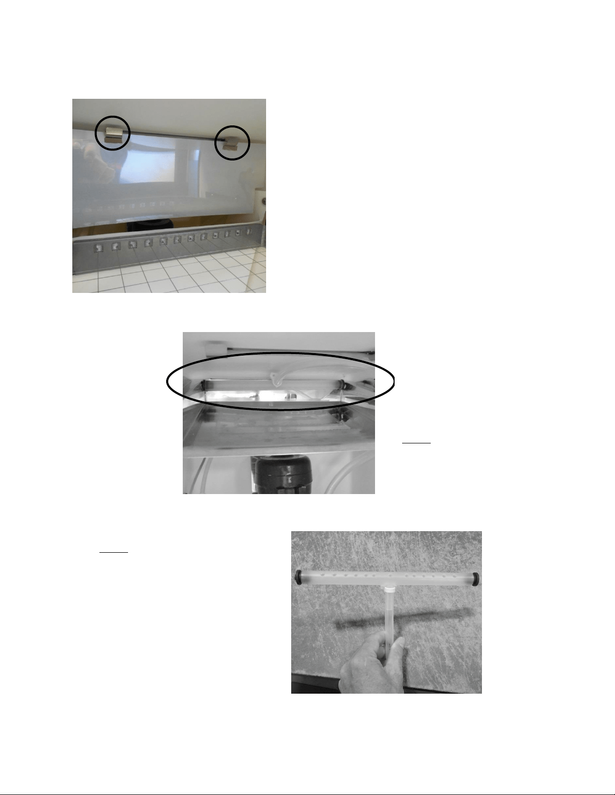
201
19.3.4 Water Deflection Shield:
19.3.5 Water Distributor Tube:
The water shield is slotted and
suspended by the two hooks
mounted at the rear top of the ice
machine.
The shield helps prevent spray from
the distributor tube from extending
outward.
The distribution tube is located above
the evaporator plate and is held in
place with the two black rubber plugs
that are inserted into each end and
placed into the holes on each end of
the evaporator plate.
NOTE: the proper installation of the
distributor tube. The supply line is
mounted towards the top of the
cabinet and secured in place.
NOTE: The holes in the distributor
tube need to be facing the evaporator
plate to ensure proper water flow
over the plate.
If the holes in the distributor tube are
facing upward, the tube needs to be
repositioned or the ice machine will
not work properly.
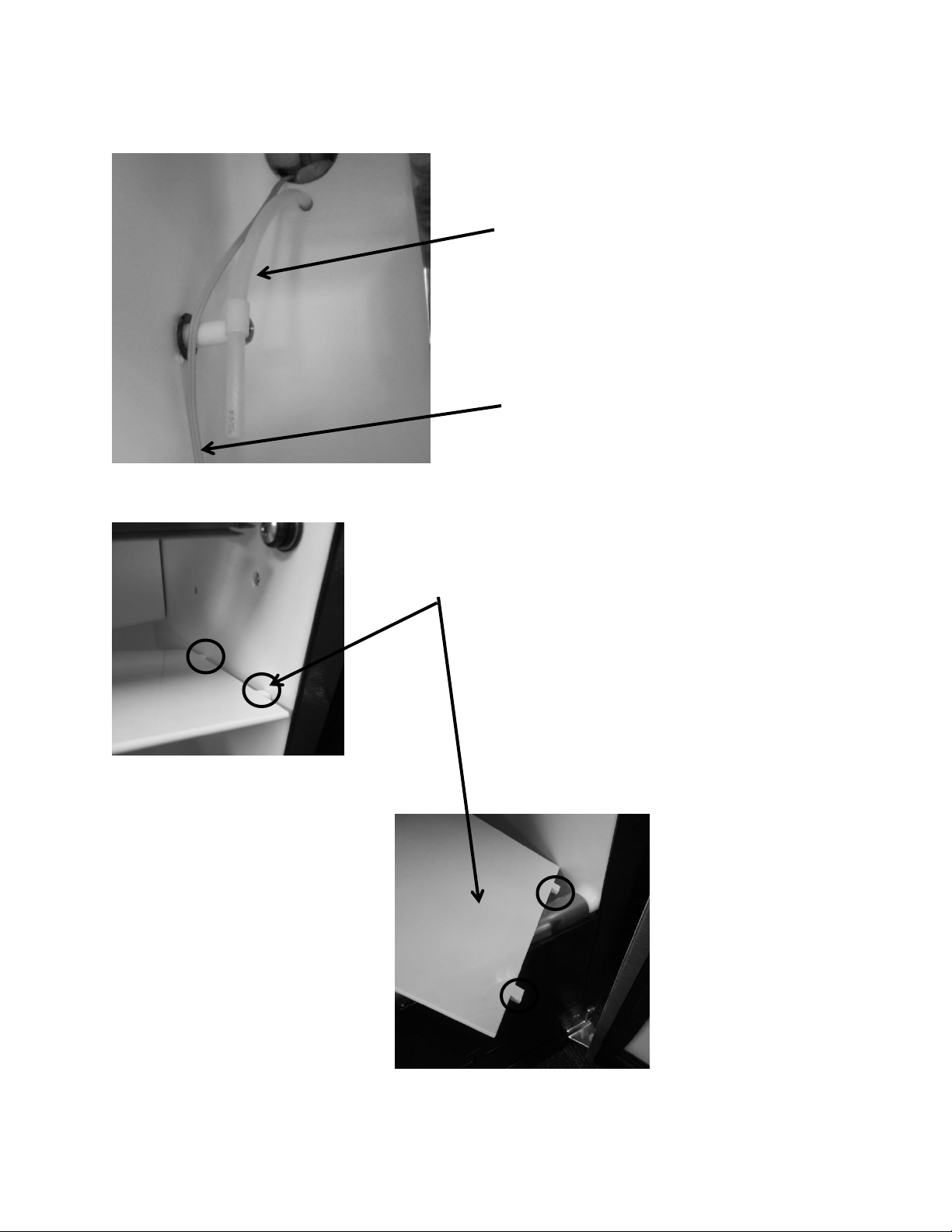
202
19.3.6 Water Fill Tube:
19.3.7 Ice Deflector:
¼” nylon fill tube, from
water valve
Plastic deflector plate; has two tabs (see below) located on the
front and rear of each end to secure into side walls of cabinet.
To remove the plate; press down on the center of the plate to
disengage from the locator holes.
To reattach, insert the tabs in the holes on one side of the
liner, lift the other end of the deflector until it locates itself
into the like holes on the opposite side of the liner wall.
Bin thermistor cable
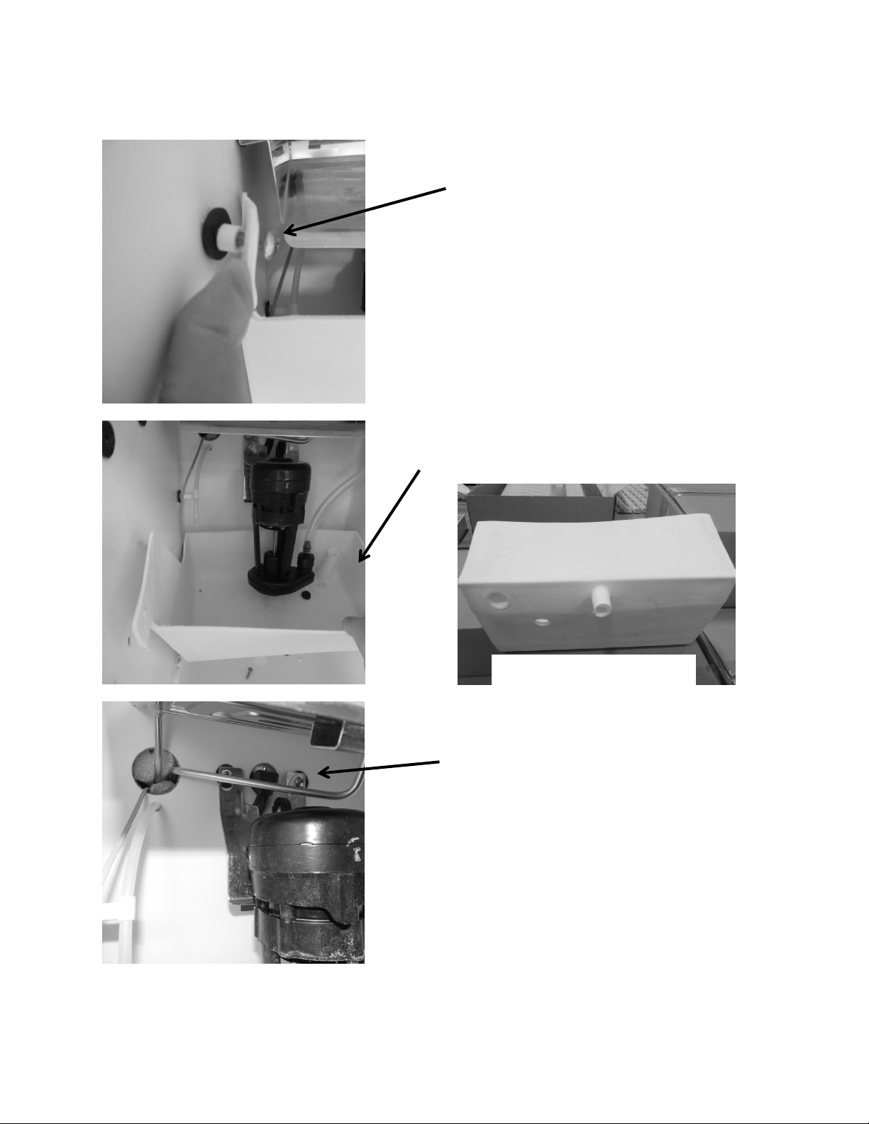
203
19.3.8 Circulation Pump and Water Reservoir:
To replace the circulation pump:
Unplug the pump from the
back wall.
Remove the two Philips
screws securing the bracket
to the back wall.
To access the circulation pump, fill
tube, water line, water reservoir, or
thermistor:
Remove the two Philips
screws securing the water
reservoir to the side walls.
The reservoir can now be removed by
lifting off the bottom drain extension.
Bottom View of Reservoir
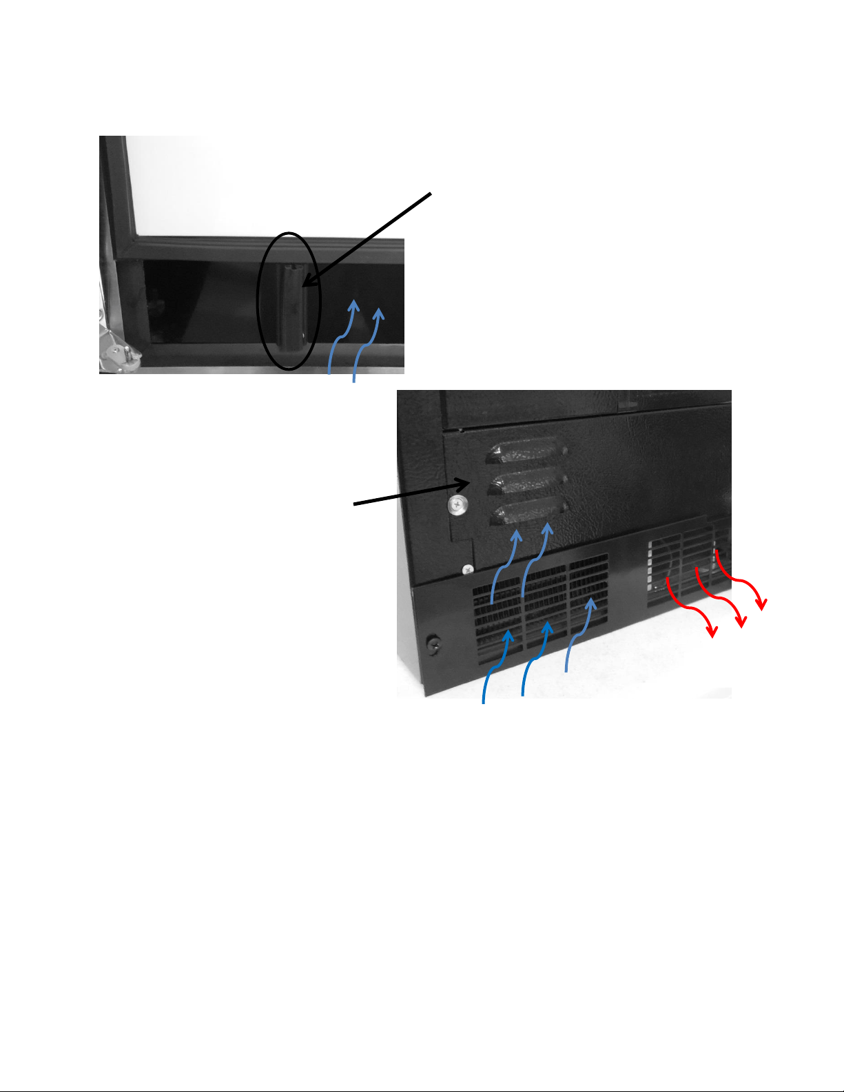
204
19.3.9 Recirculation Barrier:
Air louvers to supply additional
intake air to the condenser.
Air recirculation barrier
mounted vertically on the
bottom of the inside door
panel. This allows additional
intake air flow into the
condenser.
Intake Air
Exhaust Air
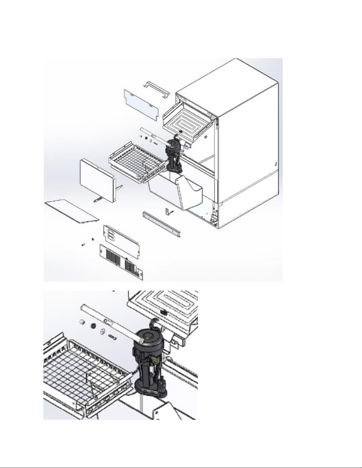
205
19.3.10 Interior Exploded View:

206
19.4: Machine Compartment Components
19.4.1 Toe Grill Removal:
1. Remove both Phillips screws on each end of the toe grill.
2. There is an oval spacer held in place by each screw, located behind the toe grill. This is
to improve the aesthetic appearance once the grill is adjusted and tightened.
Remove each Phillip screw on
both ends of the toe grill.
Right and left hand views of the
toe grill, screw and spacer.
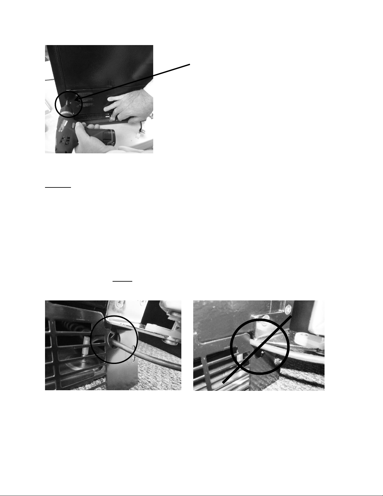
207
NOTE: When reinstalling the toe grill care must be taken to be sure that the
communication cable is routed through the correct area in the toe grill.
The below left hand photo shows the correct routing of the communication
cable, it must pass freely with clearance on all sides.
The below right hand photo shows the incorrect routing of the communication
cable. It is very easy for the cable to end up in this position if care is not taken
when reinstalling the toe grill. This is a critical pinch spot and will create a service
call in the future with either a frayed or cut cable.
NOTE: Always ensure that the plastic cable grommet is installed
correctly.
CORRECT Wire Position- Inside Grommet.
INCORRECT WIRE POSITION.
Remove each Phillip screw on each side of the
louvered access panel to gain additional access.
208
19.4.2 Warnings and Cautions:
WARNING
Prior to removing the access cover to the machine compartment, disconnect the
supply voltage to the appliance. Failure to do this could result in an electrical
shock or possible death.
CAUTION
All electrical parts and wiring must be shielded from torch flame. DO NOT allow
torch to touch insulation; the insulation will char at 200°F and flash ignite (burn)
at 500°F. Excessive heat will distort the plastic liner.
19.4.3 Mechanical Compartment:
WARNING: The refrigeration system must be evacuated prior to unsoldering the
compressor or any other system related component.
Access to the mechanical compartment is located at the rear of the unit. Most mechanical and
electrical components on the unit mount directly to the slide out base.
To gain access to the mechanical section proceed as follows; be sure to reference the photos as
called out.
1. For access to the machine compartment remove the screws securing the bottom
compartment panel at the rear of the cabinet.
2. For additional service needs, it may be necessary to slide the machine compartment
assembly out. Proceed with the following steps.
Remove the rear, upper access panel.
Back out the two Phillips screws (1 on each side) on the toe grill.
Once the toe grill is removed, it will be necessary to remove all four screws
(two on each side) to loosen the mechanical assembly from the front.
At the rear bottom corner of the unit two (1 on each side) 5/16” hex head
screws can be removed.
3. The mechanical section can now be slid out no more than 8 - 10” maximum until the
suction line has been unsoldered from the compressor.
CAUTION: To avoid kinking the suction line assembly - do not slide the
mechanical base outward past the 8-10” maximum recommended above.
4. To change the HGV or condenser it is necessary to evacuate and reclaim the
refrigerant from the system prior to this step.
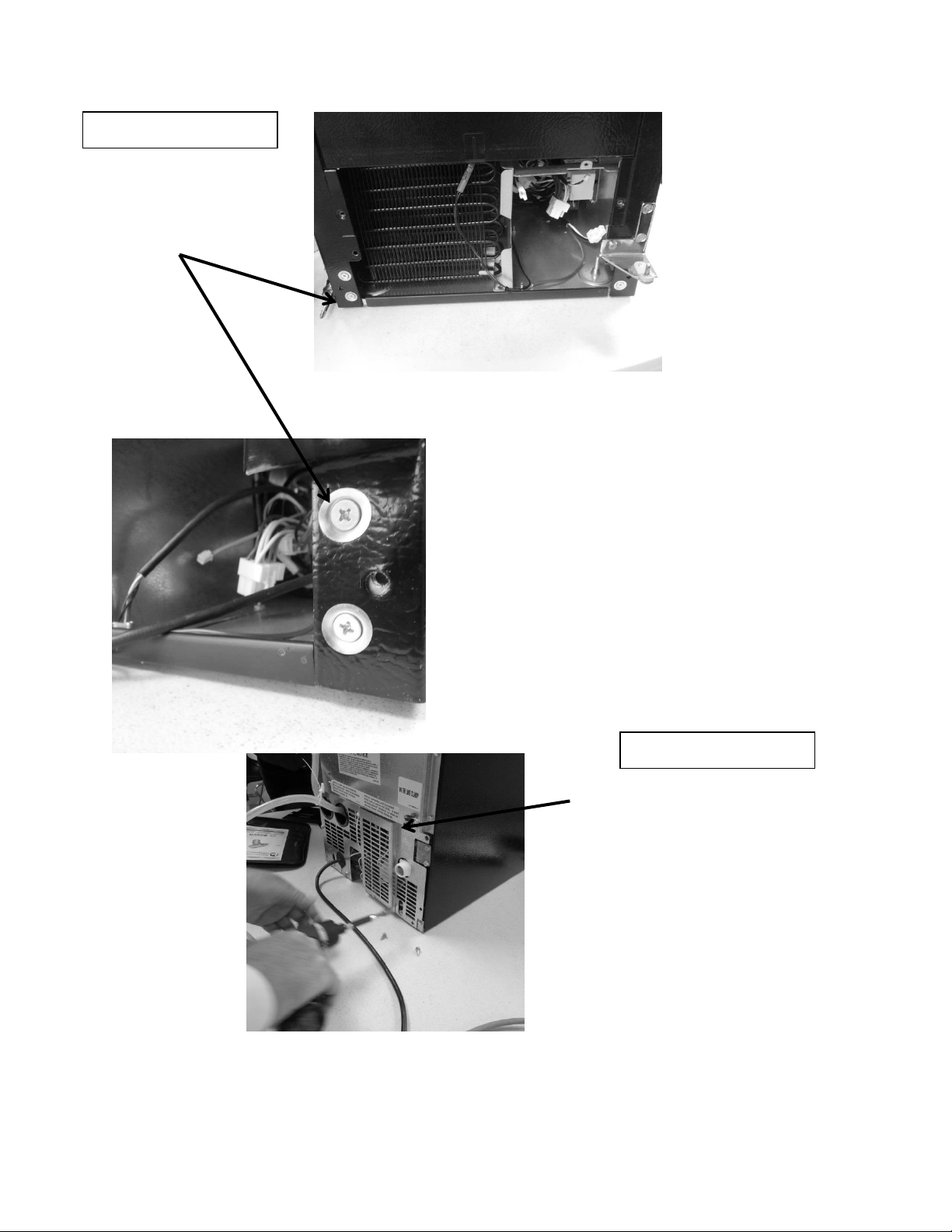
209
Remove both top
and bottom screws
on each side.
Remove all perimeter 5/16”screws
from the access panel of the lower
machine compartment.– DO NOT
remove the 5/16” screws in the
bottom left and right hand side
corners, or the Philips head ground
screws.
FRONT OF ICE MACHINE
REAR OF ICE MACHINE
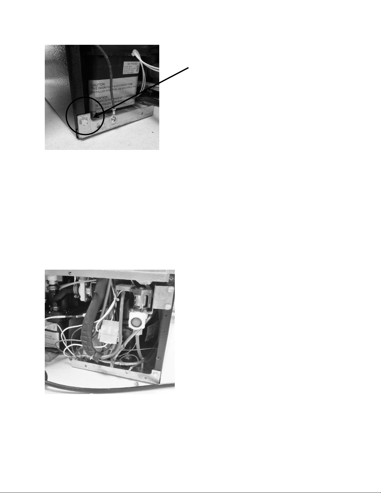
210
Before the mechanical assembly can be slid outward the following components must be
disconnected and removed.
Water fill valve
Drain valve
Drain “Y” connector
Drain pump
19.4.4 Water Fill Valve:
Remove corner screw on
each side of rear cabinet.
To remove the water valve, disconnect:
Wiring harness on solenoid.
Water connection on bottom of
valve.
Remove both 5/16” sheet metal
screws securing the valve
bracket to the side flange of the
machine compartment.
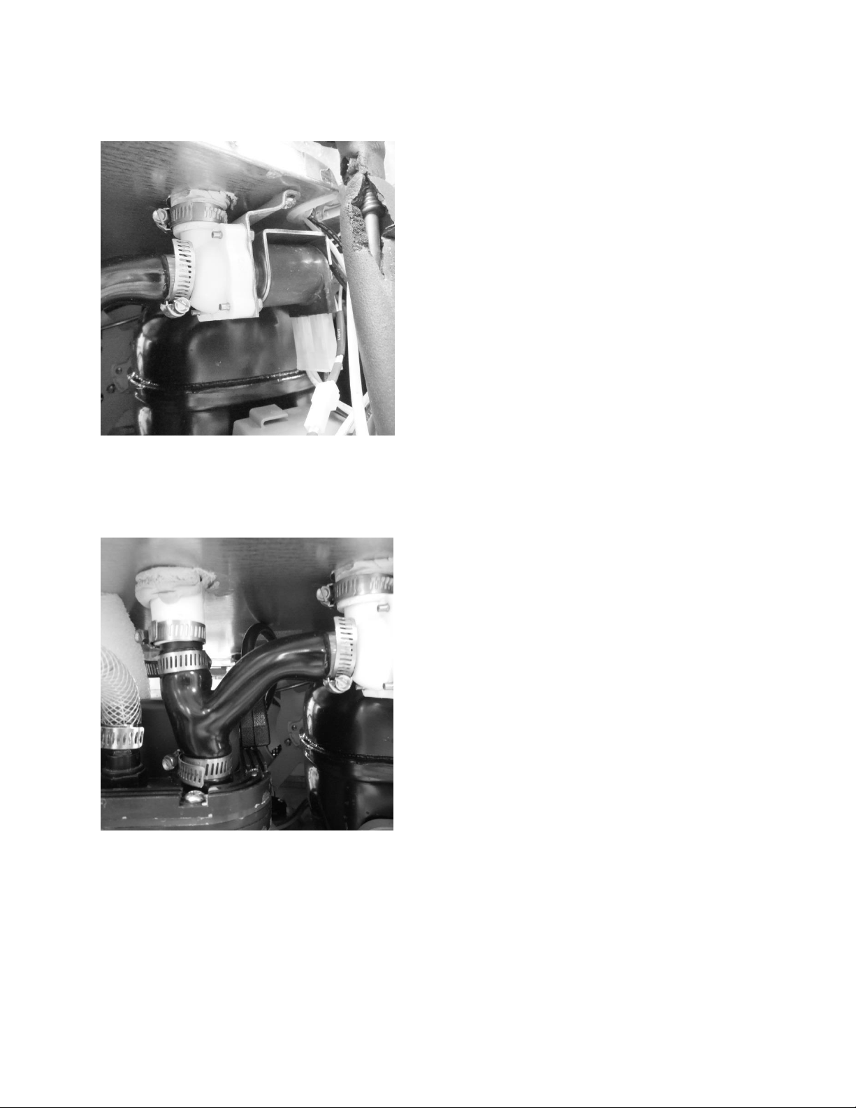
211
19.4.5 Drain Valve:
19.4.6 Drain “Y” Connector:
To remove the drain valve, disconnect:
Wiring harness on the solenoid.
The two hose clamps. One on the
top of the valve body and the
second on the side of the valve
body where it connects to the “Y”
connector.
Remove both Philips sheet metal
screws securing the valve bracket to
the top of the machine
compartment.
Remove the valve body from the
two drain hose connections.
To remove the “Y” connector, disconnect:
Loosen the two remaining hose
clamps on the top and bottom of
the “Y”.
The “Y” is flexible so it will ease in
the removal.
Remove the “Y” from the upper
nylon union and the connection at
the drain pump.
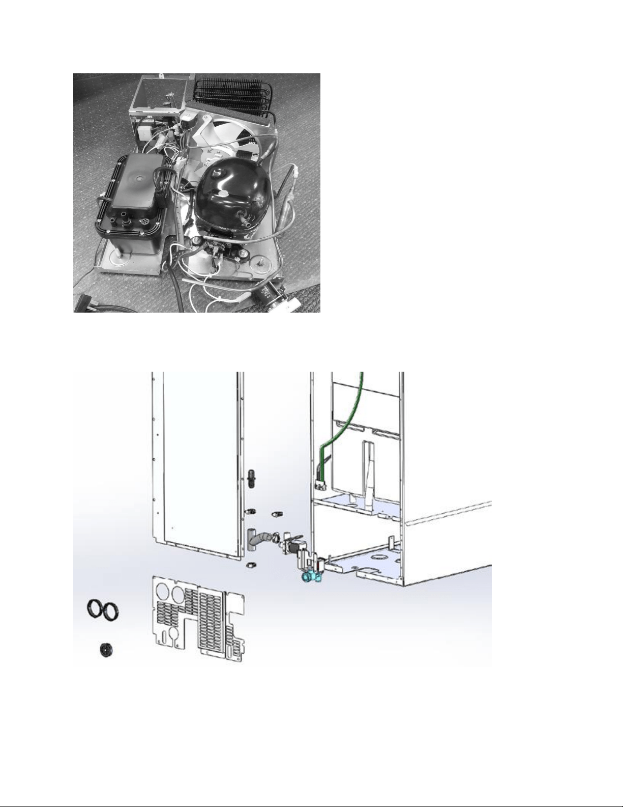
212
19.4.7 Rear View – Exploded Parts:
Mechanical assembly completely
unsoldered and removed from under
the cabinet.
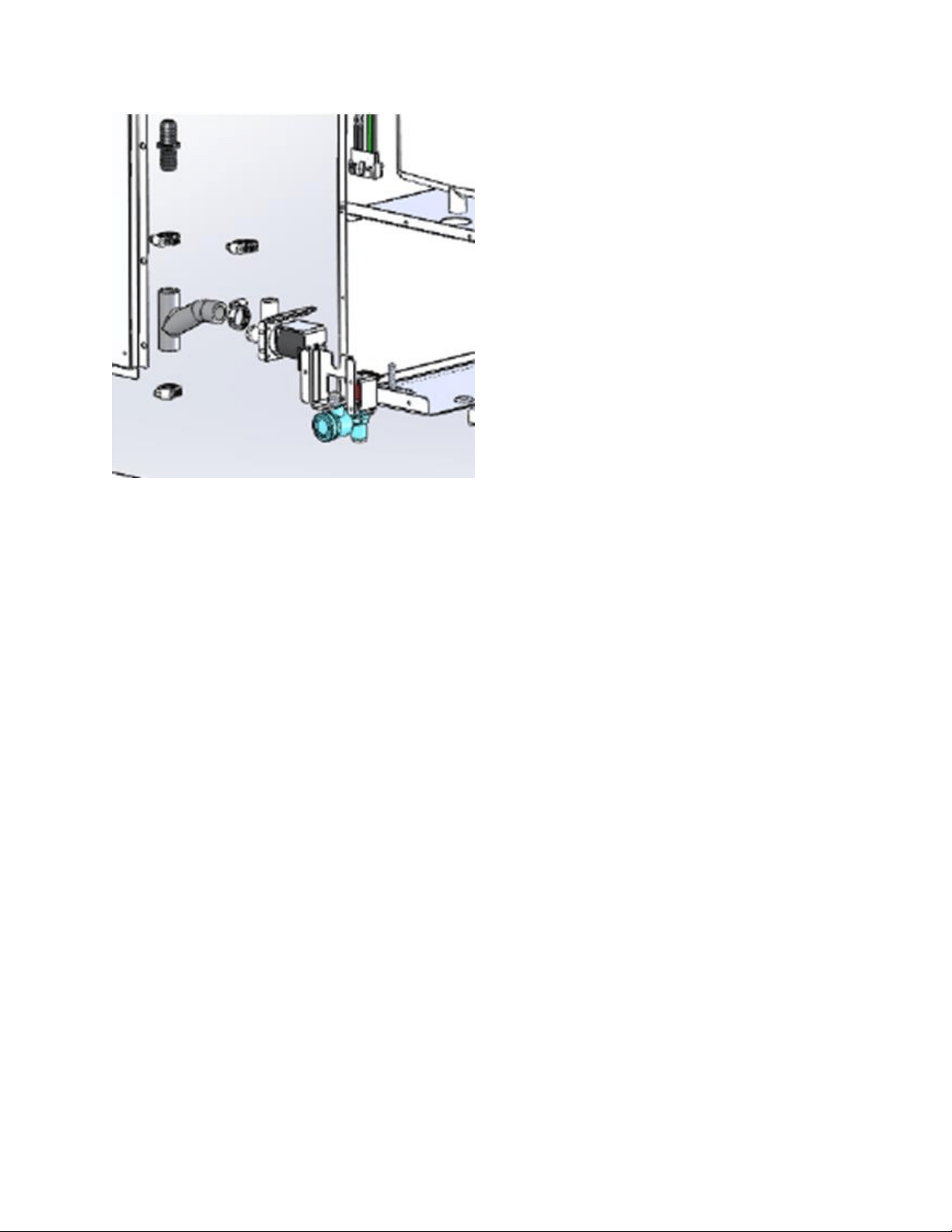
213
19.4.8 Compressor:
The following tests should be conducted before concluding the compressor is faulty.
1. Low and high side pressure, temperature of compressor, discharge and suction lines,
temperature of air leaving the evaporator compartment, temperature of condenser
coil, condenser fan operation, and amp draw at compressor.
2. Use a compressor start cord to isolate and test the compressor.
3. Use an ohmmeter to measure resistance / continuity at the compressor to check for
shorted or grounded windings.
a. Resistance between the “Common” and “Run” terminals: this will be the lowest
ohm reading obtained.
b. Resistance between the “Common” and the “Start” terminals: this will be the
mid-range ohm reading obtained.
c. Resistance between the “Start” and “Run” terminals: this will be the highest ohm
reading obtained (This should equal the combined total of the previous two
readings).
d. No resistance between any two terminals signifies an open winding.
e. Check continuity between compressor terminals and the compressor itself
(Scrape off a little paint on compressor to make sure that resistance can be
measured). If continuity is obtained, the compressor is grounded and needs to
be replaced.
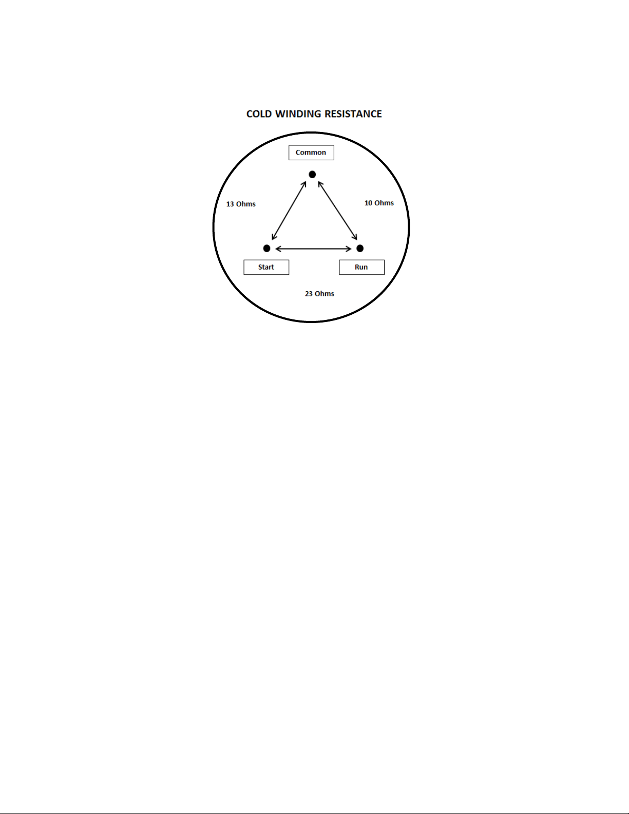
214
19.4.8.1 Check Compressor Winding Resistance:
19.4.8.2 Compressor Removal
1. Disconnect power to the unit.
2. Follow the exact steps outlined in “Sealed System Components” to access the
compressor.
3. Using the process tubes, install sealed system access valves and recover refrigerant.
4. Remove the TSD2 starter package from the compressor terminals.
5. Unsolder and remove the discharge and suction lines from the compressor.
6. Unsolder and remove the filter / drier.
7. Cap all refrigeration lines: It is advisable that all exposed refrigeration lines be capped
if the system will be exposed to the atmosphere for any length of time.
8. Remove the three 7/16” nuts, washers and grounding screw(s) from compressor
mounting bolts. There is no nut and washer at the back, left hand mounting position.
9. Lift the compressor off the mounting bolts.
19.4.8.3 Compressor Installation
1. Do not remove the rubber plugs from the compressor tubes at this time.
2. Install the four (4) rubber grommets onto the compressor base.
3. Install the three (3) sleeves where the carriage bolts are located.
4. Mount the compressor into position on the mechanical base.
5. Install the three (3) washers and lock nuts and tighten snuggly into place. Do not over
tighten.
6. Install and solder a new filter drier in the system.
7. Remove rubber plugs from compressor tubes.
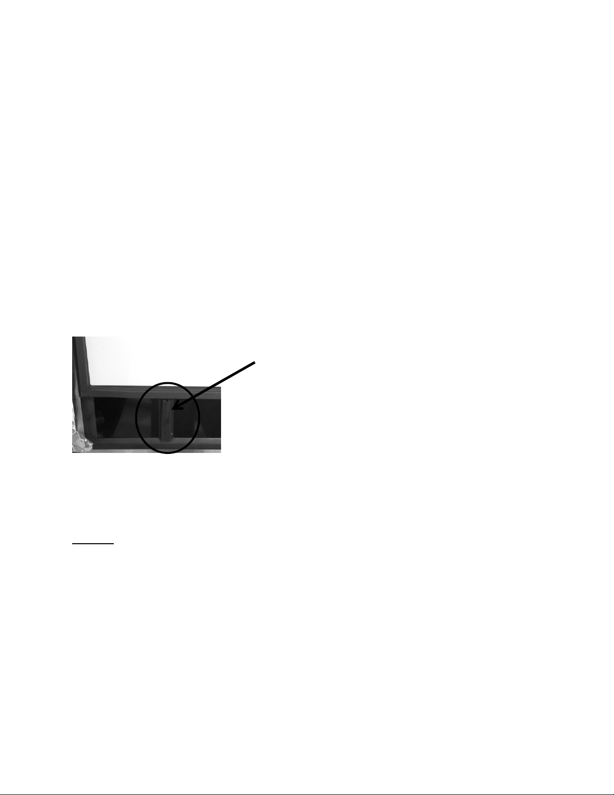
215
8. Solder a new process tube to compressor.
9. Solder the discharge and suction lines back into compressor.
10. Re-install TSD2 starter package to compressor terminals.
11. Connect service ports to both the high and low sides of system.
12. Evacuate, charge to serial plate recommendation, and leak check the sealed system.
13. Push the mechanical base assembly back into place.
14. Secure base assembly to cabinet at rear and front locations.
15. Replace the front grill and back panel.
19.4.9 Condenser:
The condenser is of tube and wire construction. It is draw through; forced air technology used
for heat transfer. The front grill facilitates both intake and exhaust air. Inlet air passes both
through the toe grill and above the louvered section on the front access panel. The condenser
sets in an enclosure that prevents air recirculation. Exhaust air passes over the main control
board and out through the toe grill. A baffle on the appliance door also aids in preventing any
air recirculation.
A common problem with this system is restricted air flow caused by lint, dust, dirt, and pet hair.
These particles become built up on the condenser and results in overheating due to the lack of
sub-cooling across the coil.
NOTE: Another important factor is that the free air space on the toe grill
cannot be altered to meet a certain design criteria. Any modifications could
jeopardize the integrity of the appliance performance.
19.4.9.1 Condenser Removal
1. Disconnect power to the unit.
2. Shut off the supply water.
3. Disconnect the drain line and drain any remaining water from the line.
4. Follow these steps to ease in the removal of the base assembly from the machine
compartment.
Baffle on the inside, lower door of the
appliance helps prevent possible air
recirculation.
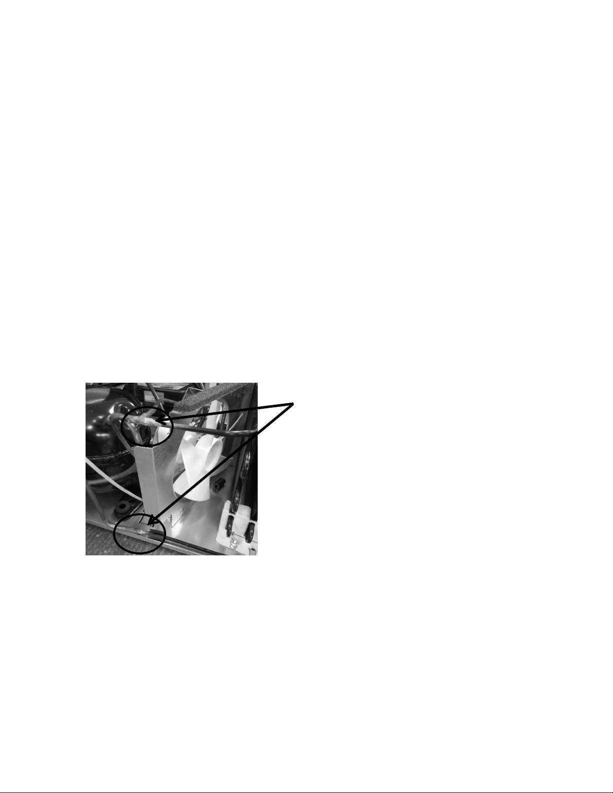
216
Remove both upper and lower, rear access panels.
Disconnect the door sensor switch.
Remove the toe grill and access panel from the front of the machine.
Remove screws from all four corners that secure the cabinet assembly to the
base assembly.
Remove these following components:
i. Fill valve, drain valve, “Y” drain connection, and door sensor switch.
5. Install sealed system access valves and recover refrigerant.
6. Disconnect and cap the suction line from the compressor and the capillary tube from
the drier.
7. Slowly slide mechanical base assembly out from the rear of the appliance.
8. Disconnect any electrical harness that restricts your progress.
9. Unsolder and remove the discharge and liquid lines from the condenser.
10. Using a 3/8” nut driver or socket, remove (1) 3/8” nut securing the outside condenser
mounting bracket to the mechanical base. The inner mounting bracket can remain, as
the condenser should slide in and out with the bracket remaining in its current
position.
11. The condenser assembly can now be removed from the base assembly.
12. It is advisable that the un-soldered copper tubes be capped if the system will be
exposed to the atmosphere for any length of time.
Unsolder the condenser at these two
points.
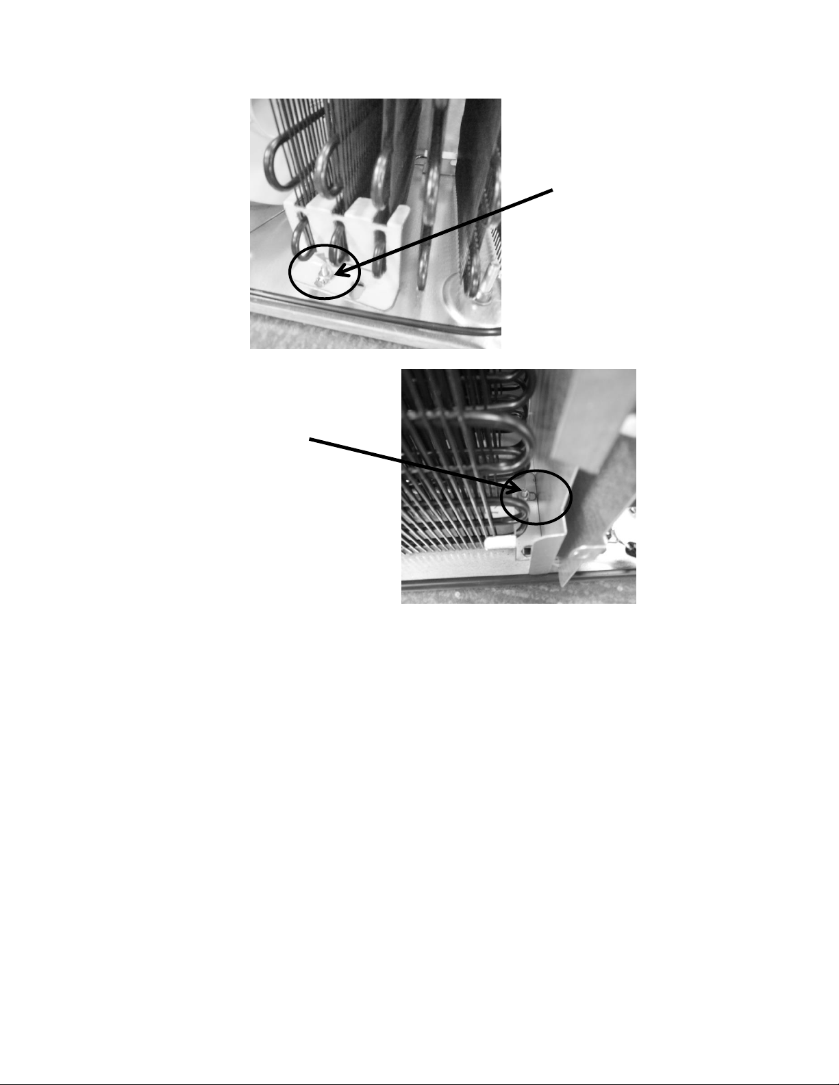
217
19.4.9.2 Condenser Installation
1. Reattach the condenser to the two mounting brackets.
2. Ensure that the carriage bolts for mounting the condenser brackets are in place on
the bottom of the machine compartment.
3. Install and solder the discharge and liquid lines to condenser.
4. Carefully slide the base assembly back in place.
5. Reconnect any electrical harnesses disconnected previously.
6. Install and solder a new filter drier in the system.
7. Evacuate, charge to serial plate recommendation, and leak check the sealed system.
8. Carefully reconnect all electrical terminals back on the terminal board.
9. Secure base assembly to cabinet at rear and front locations.
10. Reconnect the components that were disconnected earlier.
a. “Y” connector – secures and tightens all hose clamps.
b. Drain valve – secure and tighten all hose clamps.
c. Fill valve.
d. Door sensor switch and any other harnesses disconnected.
This 3/8”nut and star washer
should not have to be
removed. The condenser will
slide in and out of this
bracket.
Remove the 3/8” nut and star
washer.
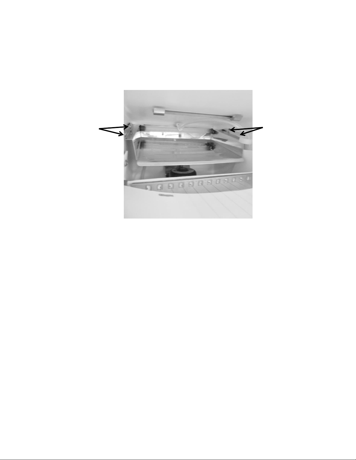
218
19.4.10 Evaporator:
The evaporator removes heat from water cascading over the plate, ultimately making a full bin
of ice within 24 hours (undisturbed cycle). The evaporator plate is “U” shaped in appearance
and is installed in the top section of the ice machine behind the escutcheon cover.
19.4.10.1 Evaporator Removal
1. Disconnect power to the unit.
2. Remove both rear top and bottom access panels.
3. Install sealed system access valves and evacuate and recover refrigerant.
4. Unsolder the suction line, hot gas line, and capillary tube from the filter drier.
5. Remove the appliance door to ease the removal process.
6. Remove the following components from inside the ice machine;
Escutcheon cover
Ice deflector
Water deflector
Grid cutter
Water distribution tube
7. Remove the four Philips pan head screws (See photo above).
8. Remove all the insulation from the bun hole.
9. Straighten out the disconnected tubing and pull the evaporator and tubing out from
the inside and discard assembly.
(4) Philips pan head
screws, 2 on each side,
front and rear of the
evaporator flange.
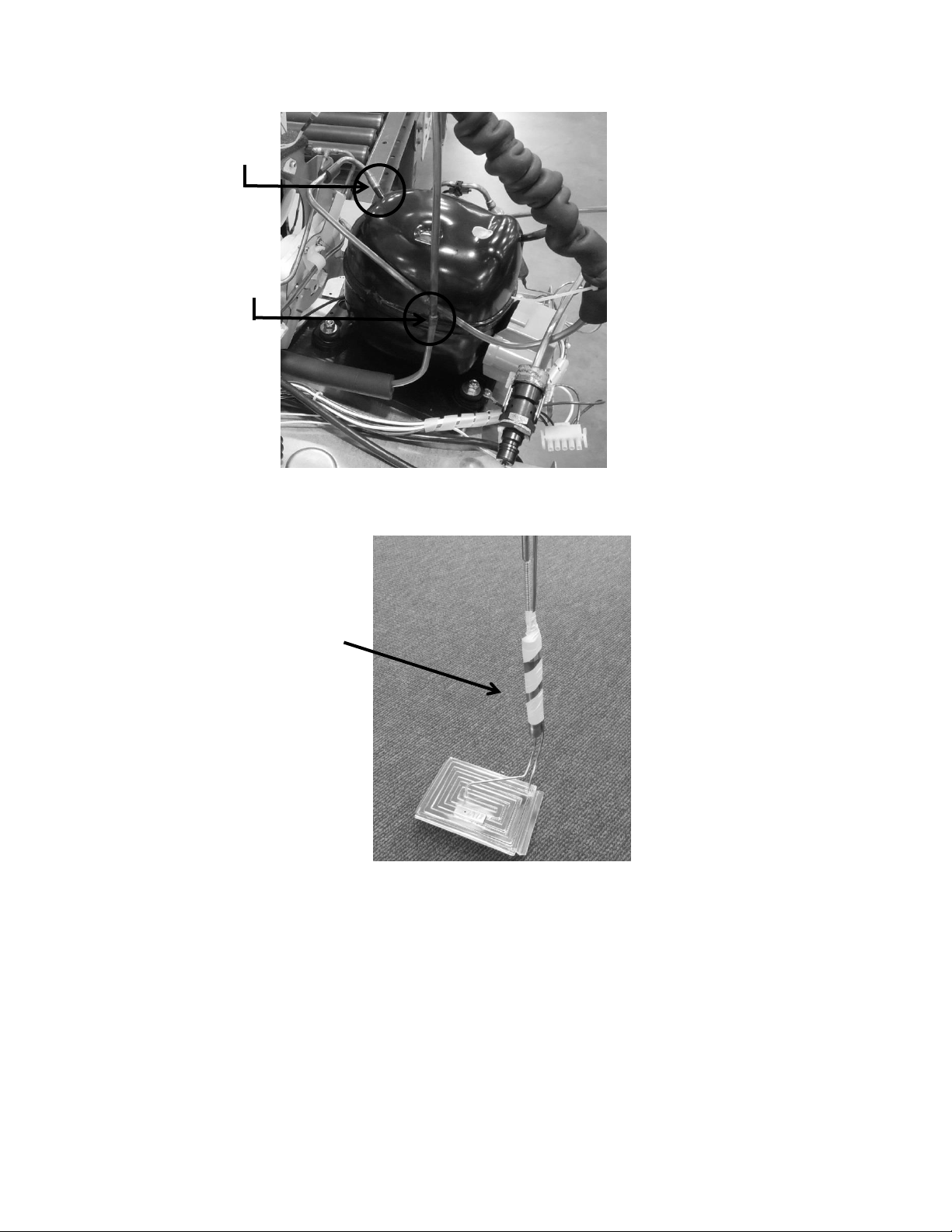
219
19.4.10.2 Evaporator Installation
1. Straighten out the tubing on the new assembly so that it can be installed.
2. Slide the tubing inside the ice machine and outward through the bun hole.
3. Bend the suction tubing outside the machine by thumb, taking care not to kink the
lines.
4. Carefully extend the tubing down the back of the machine and route tubing as was
the previous assembly.
5. Install a new filter drier.
6. Remove caps from tubing and solder lines into place.
7. Place insulation back into bun holes.
8. Screw evaporator back into place using the 4 pan head screws.
Hot gas line disconnect
Suction line disconnect
Evaporator heat
exchanger assembly
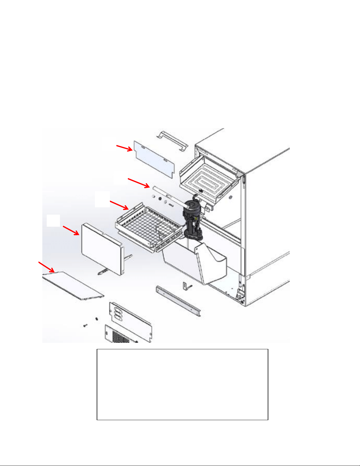
220
9. Leak check, pull a satisfactory vacuum, and recharge with R134A according to the
data on the serial plate.
10. Carefully slide the machine back into place and reconnect all components removed
from the outside of the machine.
11. Carefully reassemble the interior components removed.
12. Check drain to ensure it is not compromised.
13. Turn on the water supply to make ice.
19.4.11 Interior Components - Exploded View:
To access the evaporator plate, first remove the following:
1. Escutcheon cover
2. Ice deflector
3. Grid cutter
4. Water deflector
5. Distribution tube assembly
1
2
3
4
5
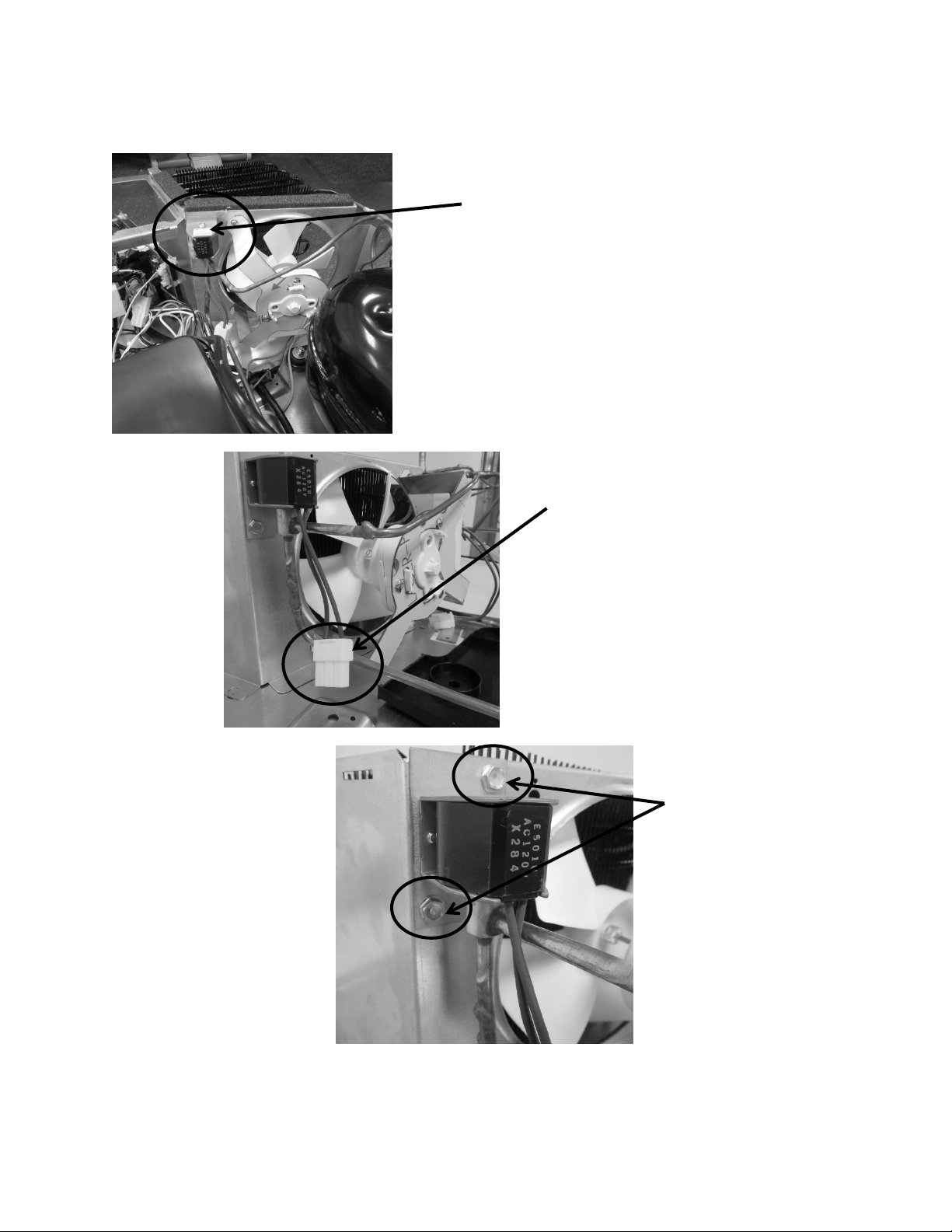
221
19.4.12 Hot Gas Valve (HGV):
Hot gas valve is located on the rear
of the condenser shroud.
Hot gas valve disconnect is shown in
photo.
The hot gas valve is secured with
two 5/16” sheet metal screws.
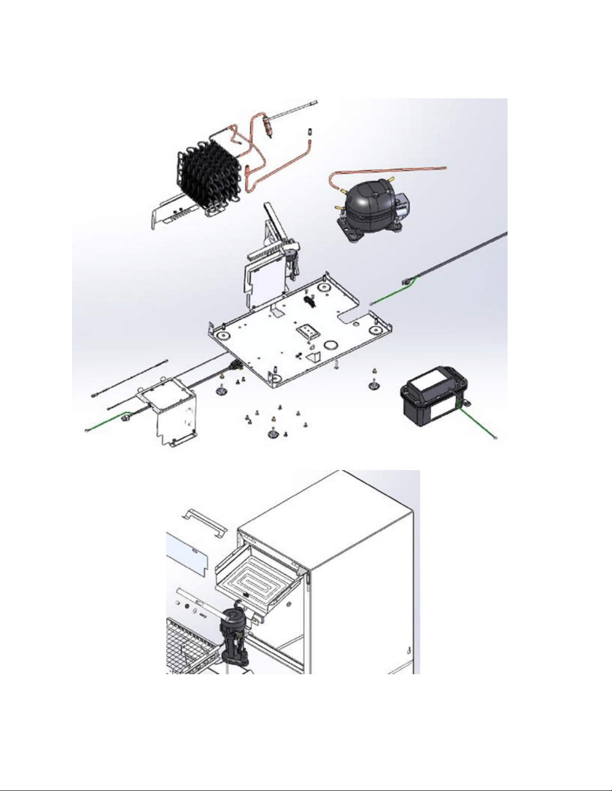
222
19.4.13 Mechanical View – Exploded:
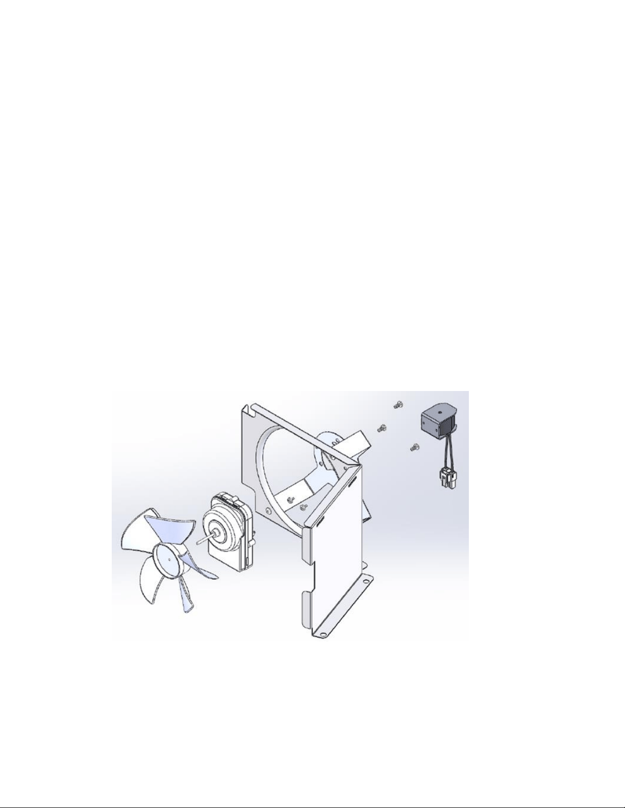
223
19.4.14 Condenser Fan:
The condenser fan is used to force air over the condenser coil. The condenser fan cycles on and
off simultaneously at intervals during the production and harvest cycles.
1. Make sure that the motor shaft turns freely. The blade can be turned in either direction
to verify that the shaft is not ceased or the blade binding. Watch the blade and listen for
any noise that might indicate a problem.
2. Check resistance between the terminals of the motor’s power cord. Replace the motor if
the windings are shorted (open).
19.4.14.1 Fan Assembly Removal
1. First, remove the fan blade from the motor shaft.
2. Remove the two Phillips screws securing the fan motor to the mounting bracket.
3. The fan assembly can now be lifted clear from the fan bracket and shroud.
4. Disconnect the fan assembly at the connector harness.
19.4.14.2 Exploded View of Condenser Fan assembly
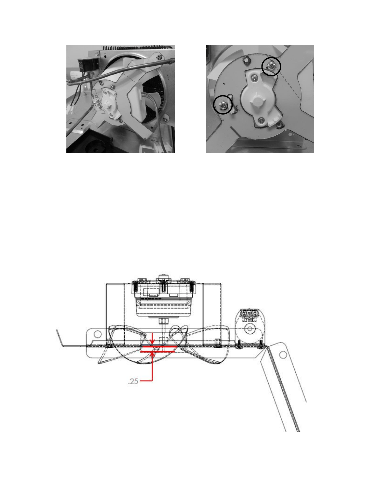
224
19.4.14.3 Fan Assembly Installation
1. Re-install the fan motor in reverse order that it was removed.
19.4.14.4 Condenser Fan Blade Spacing
If the condenser fan blade has been removed from the motor shaft the fan blade must be
properly re-spaced to achieve the optimal performance from the condenser.
The correct distance from the tip of the fan shaft to the top surface of the fan blade hub is
1/4” (.25”)
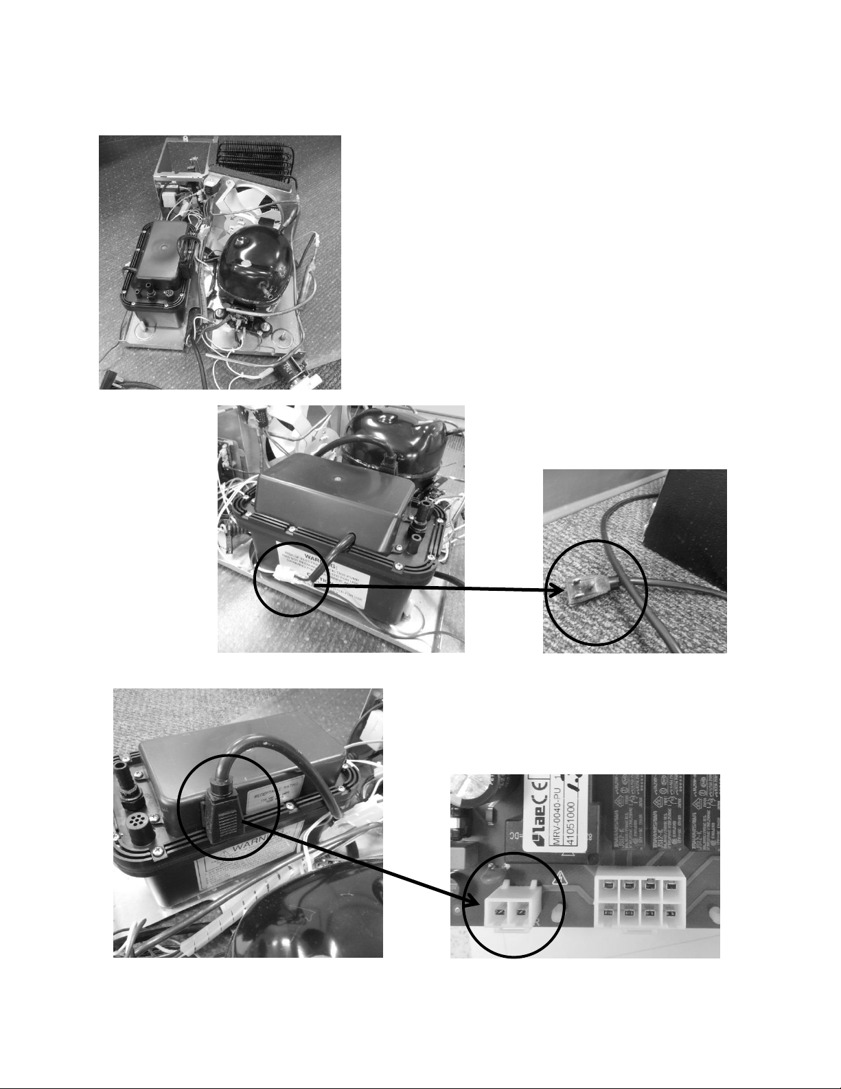
225
19.4.15 Drain Pump:
The drain pump sits at the rear, left hand side of the
machine compartment base assembly.
Pumping capacity is rated at a maximum of: an 8’
vertical lift and a 20’ horizontal run.
Any use of a non-manufactures approved drain pump
will void the consumer’s warranty.
The white connector at the drain pump
connects the appliance to the supply
voltage receptacle.
The black power plug on the pump
connects to the main power board.
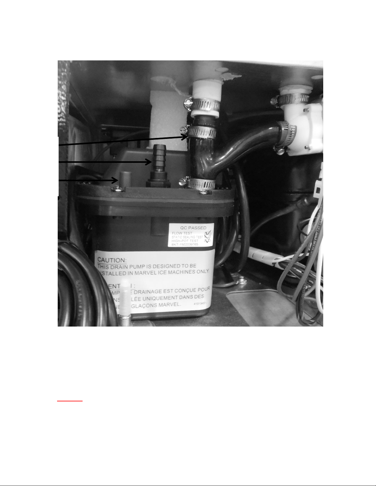
226
19.4.15.1 Drain Pump Tube Routing
1) Pump Inlet, from bin/reservoir.
2) Pump outlet, has a maximum limit of 8’ vertical lift and 20’ horizontal run.
3) Pump vent, must be attached vertically to the rear of the cabinet.
NOTE: The ice machine and drain pump need to be winterized once
temperatures drop below 40°F to avoid damage caused by water
freezing in the water system. Water needs to be drained and lines need
to be blown out to preserve the appliance through the cold months.
1-
2-
3-
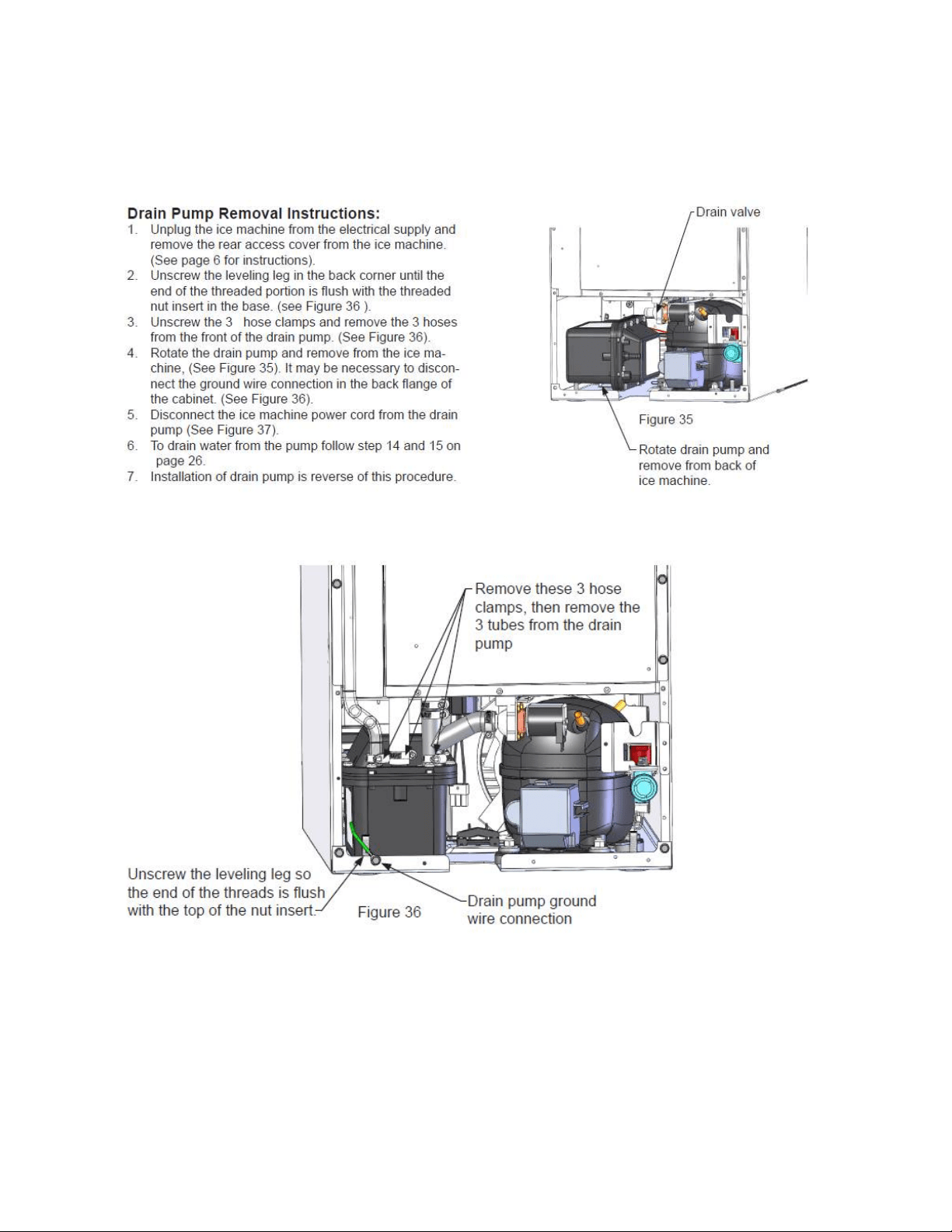
227
19.4.15.2 Drain Pump Removal Instructions
The following instructions were taken from the Customers Owners Guide

228
19.4.15.3 Additional Inspection Issues upon Replacement:
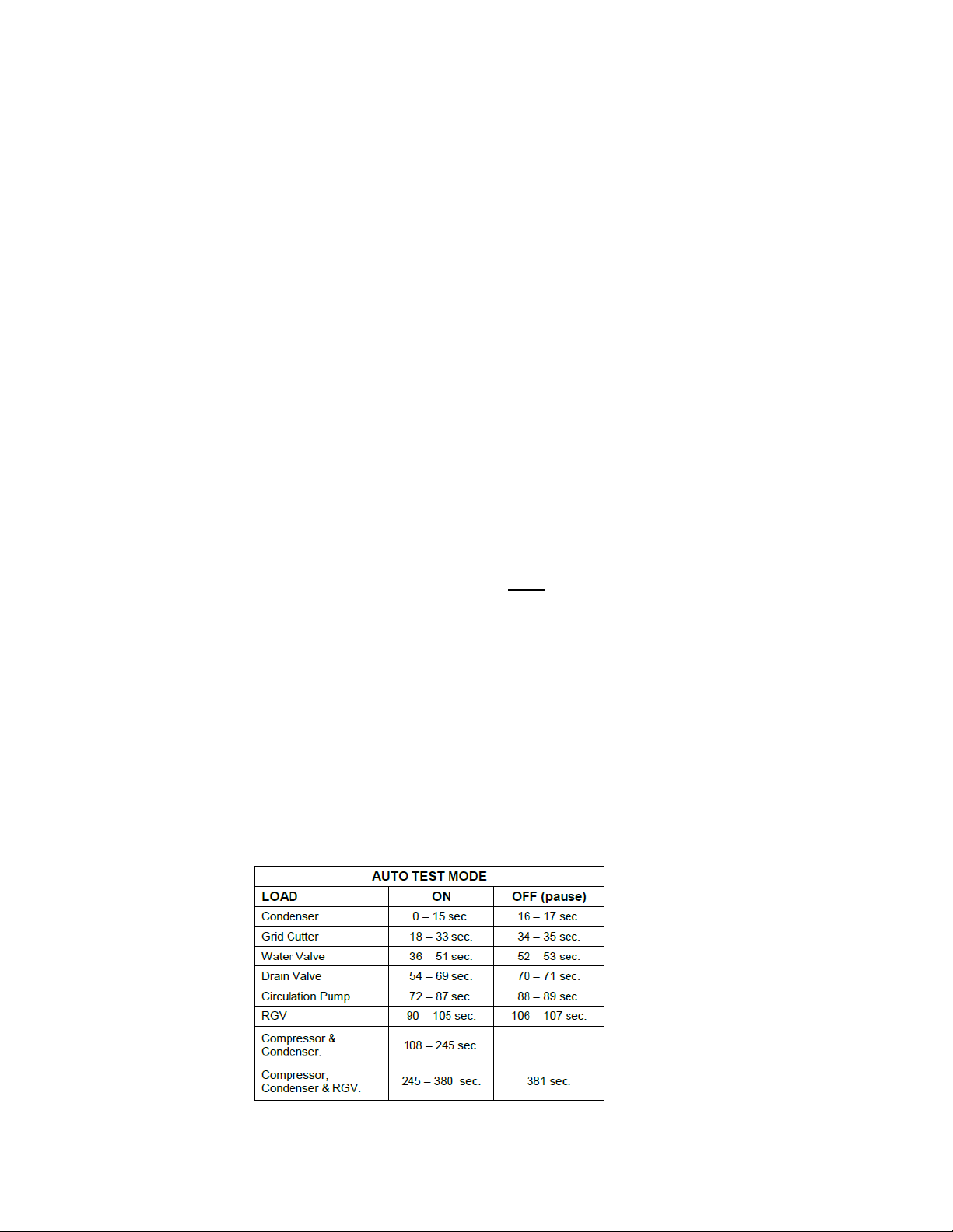
229
19.5: Diagnostic Test Modes
19.5.1 Power on Reset (POR) Auto Test Mode:
Every “power on reset” (POR) will initiate with an “auto self-test”. The user interface display will
simulate normal operating conditions during the auto self-test.
This auto self-test mode will initiate at the beginning of the initial appliance start-up and after
power is restored after every loss of power that might occur due to customer or supply voltage
reasons. This function could result in a service call, so it’s possible that customer education
could be applied.
During the POR auto self-test mode, the appliance will operate as follows:
The display will show the last machine state.
The interior lights will function normally.
The “Lock” feature will function normally.
The “ON/OFF” key works normally.
o NOTE: if the appliance is turned “Off” during the POR self-test, the appliance will
be disabled immediately.
The “Delay Start” feature works normally.
o NOTE: if “Delay Start” is selected during the POR self-test, the appliance will
enter the selected delay start setting after the completion of the POR self-test.
19.5.2 Manual Auto Test Mode:
The manual auto test mode is activated manually by pressing and holding the “LOCK” key then
pressing the “Delay Start” key (again still while manually pressing and holding the “Lock” key).
The display will flash 5 times to indicate that the manual auto test mode has been enabled.
NOTE: The execution of the auto test sequence is identical in either the POR auto test or
manual test mode.
19.5.3 Appliance Component Test Sequence while in Auto Test:

230
This control operates on a timed cycle event. The control performs a “Power on Reset” test
at the beginning of each power up event (initial startup, after loss of power, etc.). Each
individual component is tested prior to the harvest cycle. The harvest cycle current timing is 5
minutes; production cycle is 45 minutes at a 55°F ambient. An additional 45 seconds are
added for each degree the condenser outlet temperature rises over 55°F.
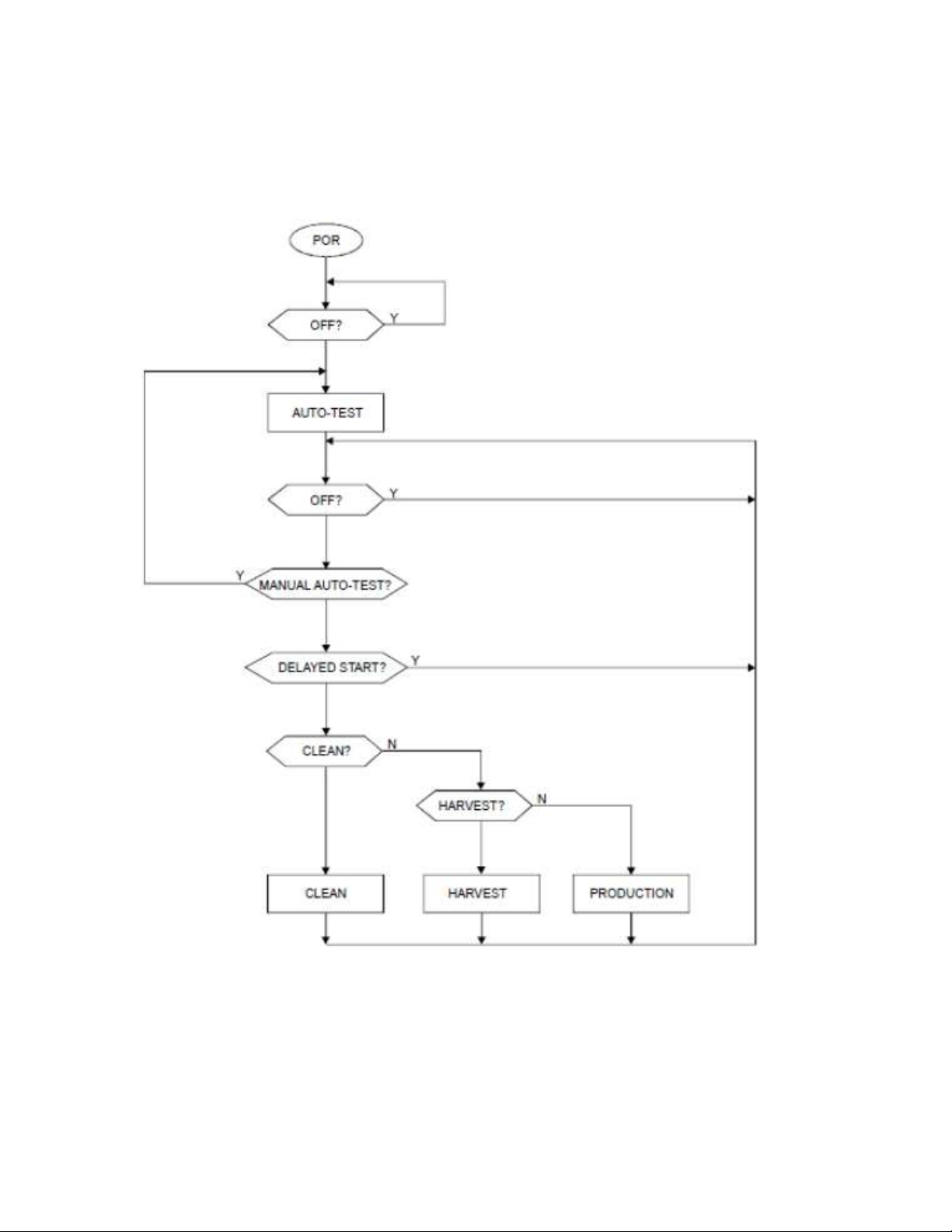
231
19.6: Diagnostic Charts
19.6.1 Operation Mode:
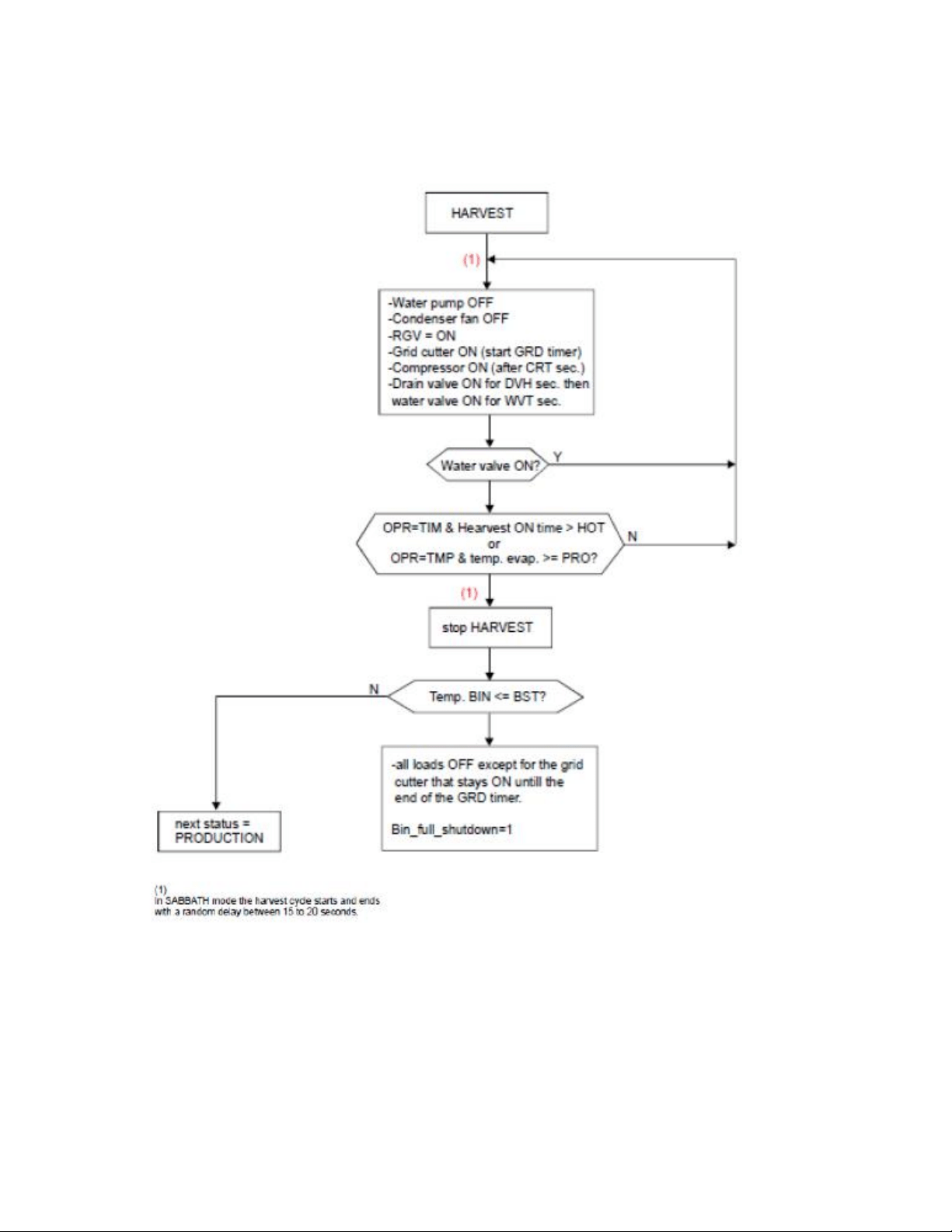
232
19.6.2 Harvest Mode:
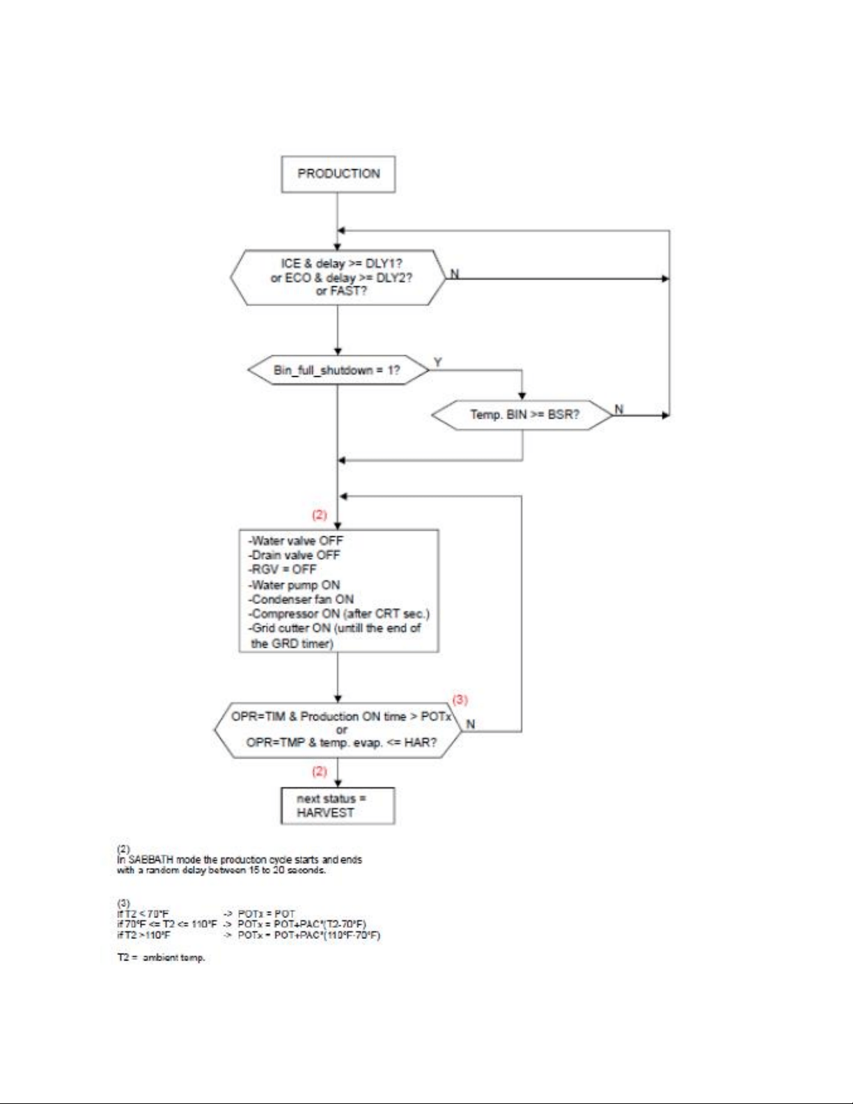
233
19.6.3 Production Mode:
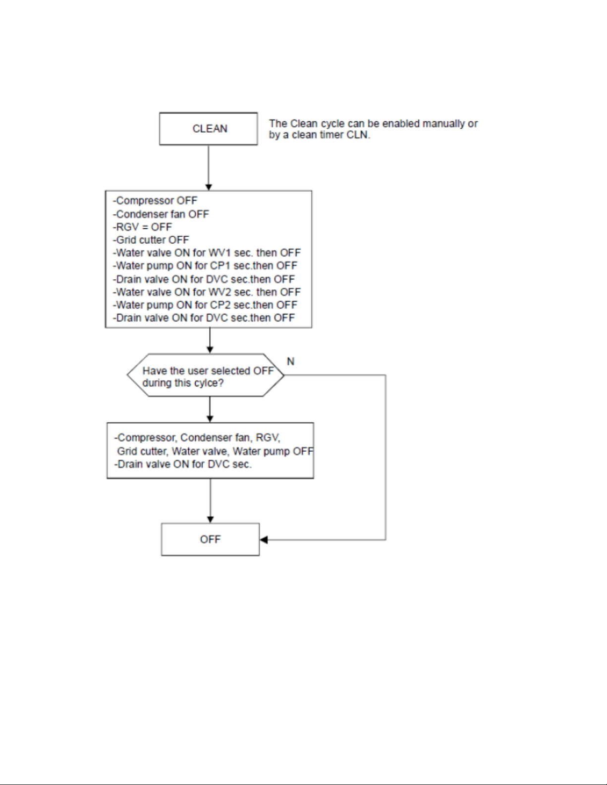
234
19.6.4 Clean Mode:
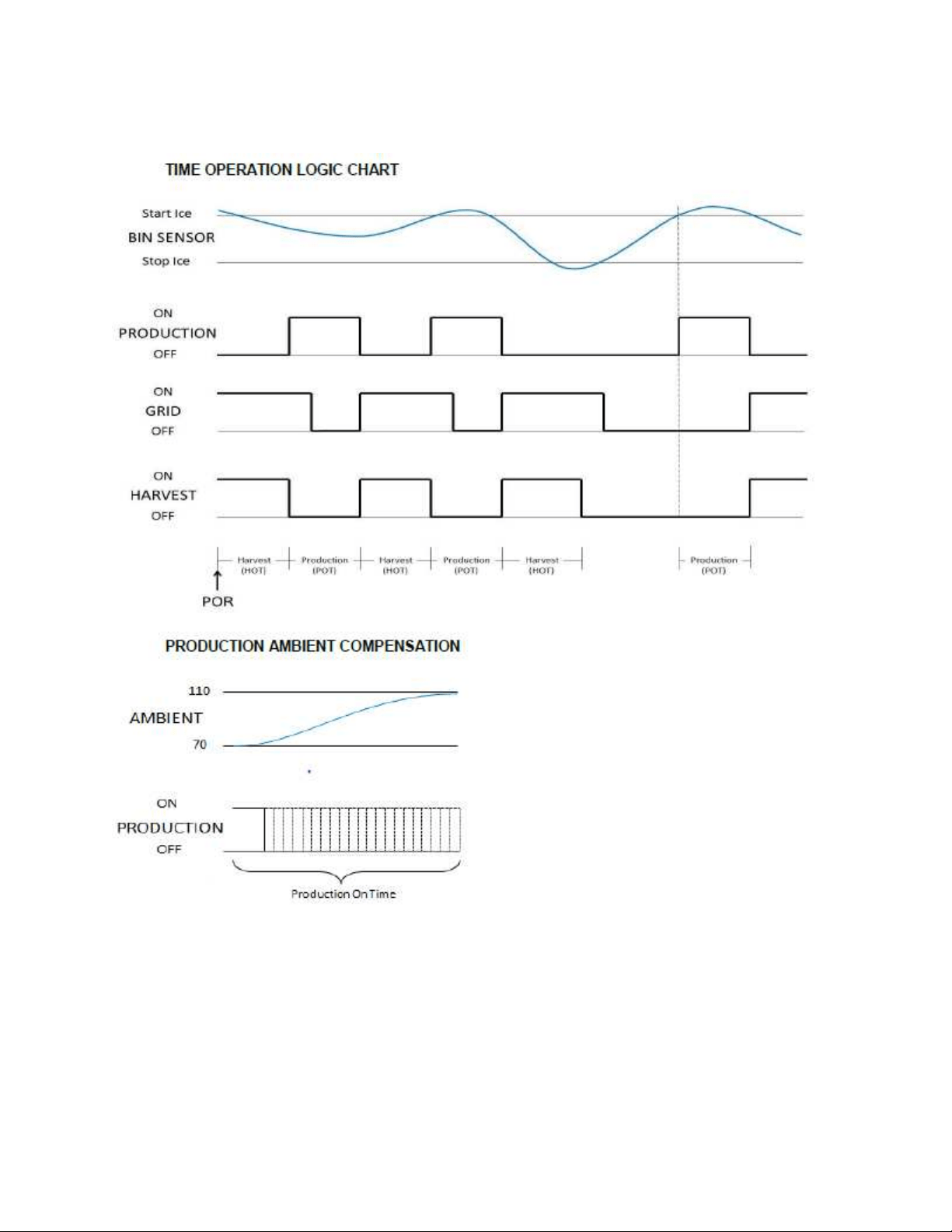
235
19.6.5 Production and Harvest Cycle Characteristics:
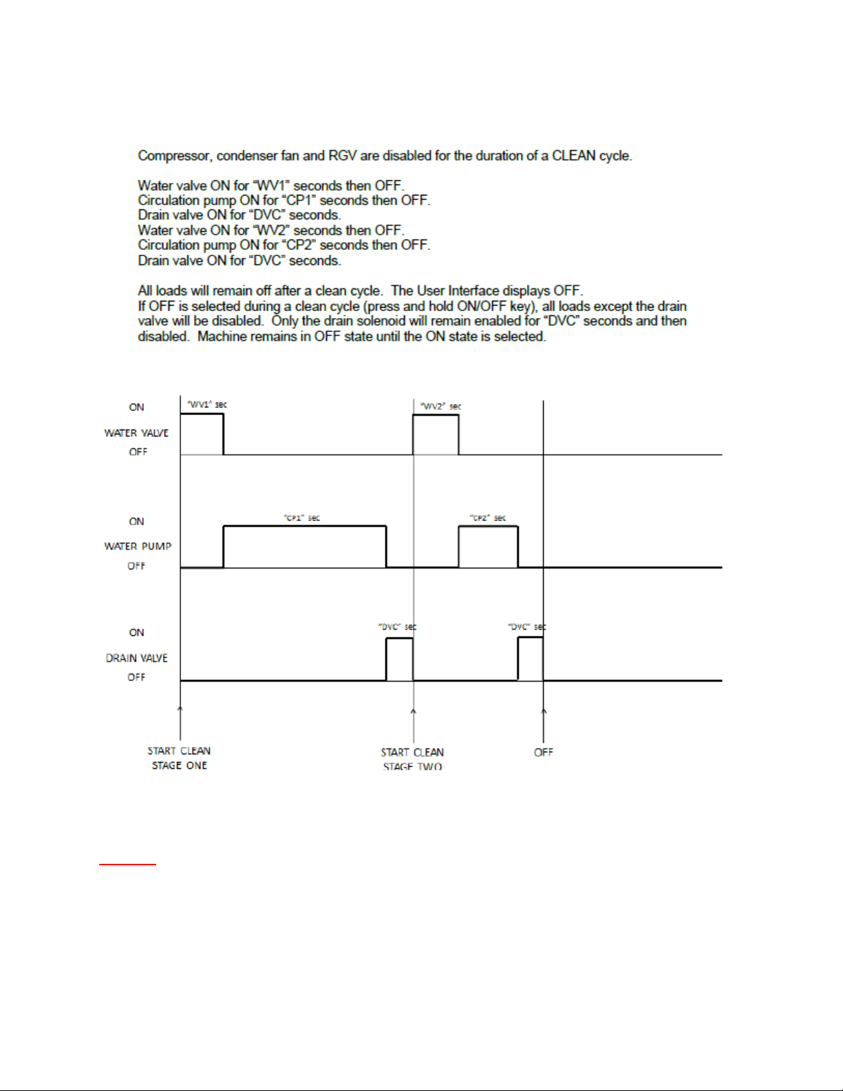
236
19.6.6 Clean Cycle:
NOTE: It takes 26 weeks of total accumulated compressor run time to
activate the next defrost period.

237
19.7: Trouble Shooting
19.7.1 Ice Machine Operation:
19.7.1.1 Ice Machine does not operate:
1. Is the machine power cord plugged in?
2. Is the electronic control showing the “ICE” position?
3. Is a fuse blown or breaker tripped?
4. Is the room temperature cooler than normal?
a. Minimum room temperature for an ice machine to operate efficiently is
55°F (13°C). The bin sensor may sense a full bin condition and prevent the
ice machine from going into a production mode.
5. Does the appliance have a drain pump?
a. The drain pump may be removing water from the system.
19.7.1.2 Ice Machine is noisy:
1. Can water be heard circulating in the ice machine?
2. Customer education is a possibility: The process of making ice involves a
refrigeration cycle, water circulation and a combination of solenoids, valves, and
motors. It is not a quiet procedure.
19.7.2 Ice Production:
19.7.2.1 Little or no ice:
1. Is the control set to the “Ice” position?
2. Is the supply water present at the fill valve?
3. How long has the ice machine been running?
a. A typical production cycle can take up to 1 ½ hours. Start time is typically
longer at the initial start-up. After 24 hours, the bin should be near
capacity without any consumption.
4. Is the water reservoir drain plug in place?
5. Is water flowing out of the water distribution tube?
6. Is the condenser fan operating without restrictions in the air flow?
7. Is the room or water temperature too warm?
a. Maximum ice capacity is achieved in an ambient less than 90°F (32°C). It
is also recommended that the ice machine not be placed in direct
sunlight, next to a stove, range, space heater, hot air registers, hot water
radiators, or any other type of direct heating source. Excessive heat will
deter ice production and storage.
b. It is important to realize that the ice bin is not a refrigerated
compartment. Cooling for ice storage is essentially created by the ice
itself.
8. Is there scale built up in the ice machine?
a. Initiate a clean cycle with a recommended nickel-free cleaner.

238
19.7.3 Ice Quality:
19.7.3.1 Odor, greyish color, or off- tasting
1. Check for mineral scale build up on the evaporator plate.
a. Initiate a clean cycle with a recommended nickel-free cleaner.
2. Does the supply water have a high mineral content?
a. Installation of a water filter in the supply line is recommended.
3. Are any food types (or items) stored in the ice bin?
a. If so remove them.
19.7.3.2 Ice Clumps
1. Look for clumps of ice in the bin.
a. Ice machines with low consumption rates tend to have “fused” or
clumped ice. This is caused by water refreezing and fusing cubes
together.
b. In severe cases, the ice will become stale and frosty in appearance.
19.7.3.3 Small Cubes
1. How often is ice being consumed?
a. As mentioned above, low consumption rates affect ice quality. Unused
ice will melt while inside the storage bin. This is often more noticeable
when the bin is less than ¼ capacity.
2. Is the water supply adequate? Look for a restricted supply filter.
3. Look for loss of water in the reservoir. Is the drain or drain valve seeping?
4. Is the water distribution tube restricted?
a. Initiate a clean cycle with a recommended nickel-free cleaner.
19.7.4 Plumbing Issues:
1. Is the drain hose aligned properly with the drain?
2. Is the ice machine draining properly?
a. Avoid kinks and restrictions in the drain line.
b. Check for foreign objects blocking the inside of the drain system
(inside and outside the machine).
c. Ensure that the drain pump is installed level.
d. NOTE: It is recommended that external plumbing issues should be
address by a licensed plumber.
19.7.5 Drain Pump Troubleshooting:
19.7.5.1 Check the following if the ice machine isn’t working
Make sure there is voltage at the receptacle.
Make sure the ice machine is turned “On”.
Make sure the ice bin is not full.
Confirm the operating status of the drain pump.

239
Supply voltage to the ice machine will be interrupted if the drain pump
becomes full.
19.7.6 The Drain Pump is Inoperative:
1. Verify that the power cord is connected at the pump (2 locations) and the
main power board.
2. Look for possible restrictions in drain lines.
3. Ensure that the vent line is clear and able to breathe.
4. Not enough water to turn pump on.
a. At least 1 quart (.95 liters) of water is needed to activate the
pump.
19.7.7 The Drain Pump runs but not pumping:
1. Look for possible restrictions in drain lines.
2. Ensure that the vent line is clear and able to breathe.
3. Check to see if the drain line is to specifications.
a. Maximum lift is 8 feet (2.44 meters).
b. Maximum run is not greater than 20 feet (6.1 meters).
19.7.8 The Drain Pump runs momentarily and shuts off:
1. Ensure that the drain and vent lines are free and unrestricted.
2. Verify that the drain pump is level.
3. Look for loose voltage connections; inspect the power cord where it is
connected at the pump (2 locations) and the main power board.
19.7.9 Thermistor (Sensor) Error Detection:
Temperature thermistors are monitored continuously by the main power board. Any “OPEN,
SHORTED, or OUT of RANGE” thermistor circuit will initiate an alarm.
If an error is detected, the ice machine will immediately shut down and the display interface
will flash the corresponding fault code continuously. No audible alarm will sound.
19.7.10 Communication Error:
Loss of communication between the main power board and the user interface will result in
either a continually flashing “ON” or “OFF” on the display.
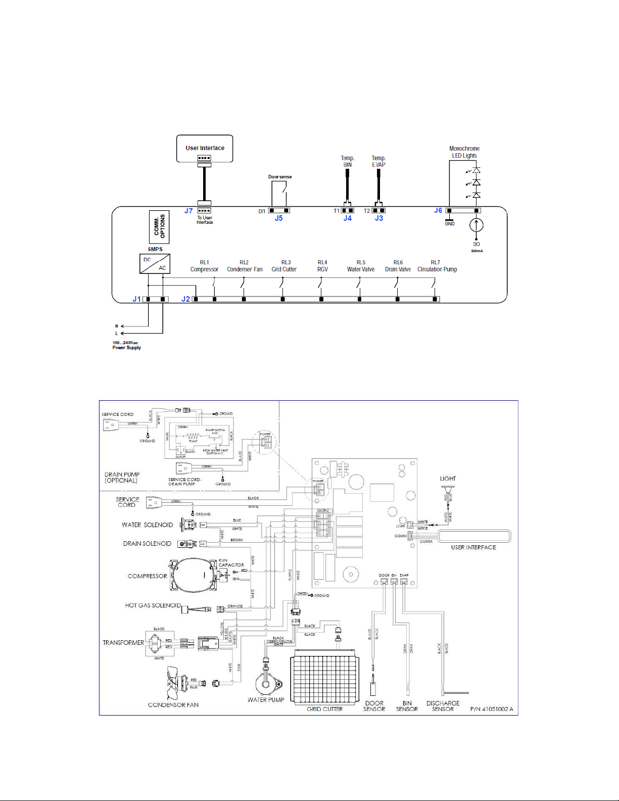
240
19.8: VAC Wiring Diagram and Schematics
19.8.1 Block Diagram of Main Power Board:
19.8.2 Wiring Diagram:
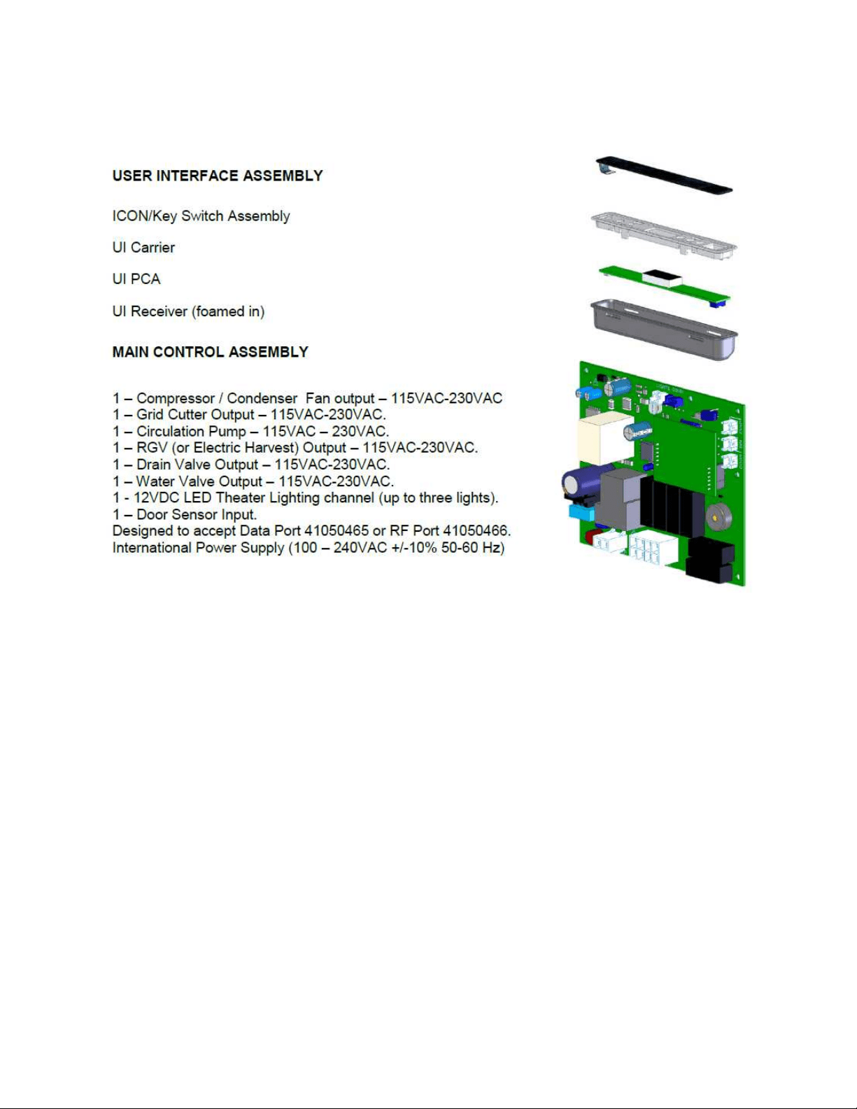
241
19.8.3 Main Power Board Identification:

242
19.9: Specifications:
19.9.1 Ice Machine Components:
19.9.1.1 Output Loads (120V/60Hz)
Compressor: Embraco EMY70
Condenser: Panasonic FDQR107S2LNM
Transformer: Basler 120V, 0.24A / 12V, 25VA
Water Valve: Horton S30 120V, 12W
Drain Valve: Horton S90 120V
Circulation Pump: Beckett 120V, 220mA
LED Lights: 12VDC, 350mA, constant current LED driver
19.9.1.2 Input Loads
Bin Temperature Sensor (thermistor): NTC/ 10K@25C
High Side Temperature Sensor (thermistor): NTC/10K@25C
19.9.2 Ice Machine Specifications:
Voltage: 120 VDC
Frequency: 60 Hertz
Amperage: 3.0 Amps Start
1.73 Amps Running
Wattage: 121 Watts
Compressor: 450 BTU’s
Condenser Fan Motor: 4.1 Watts
0.7 Amps
Refrigerant Charge: 5.0 oz.
System Pressures (Stabilized): 178 PSI High Side
25 PSI Low Side
Cabinet Dimensions Width: 14.88”
Height: 33.75-34.75”
Depth: 23.62”

243
19.10: Production and Harvest Guidelines
19.10.1 Harvest Cycle:
1. During “Harvest” time; the circulation pump and condenser fan outputs are disabled.
2. The compressor, hot gas, and drain valves are enabled.
3. The drain valve will remain enabled for 60 seconds before becoming disabled.
4. The fill valve will be enabled for 150 seconds before becoming disabled.
5. The compressor remains enabled.
6. All loads will remain in this state until the end of the harvest time (beginning of next
production time).
7. All harvest events will enable the grid cutter.
19.10.2 Production Cycle:
1. During the “Production” time; the circulation pump, condenser fan, and compressor are
enabled.
2. The fill valve and the drain valves are disabled.
19.10.3 Timed Operation for Harvest and Production:
1. The high side thermistor senses the temperature of the liquid line at the filter drier inlet.
2. If the bin thermistor senses a temperature at or below the “Stop Ice” set point, any
occurring production or harvest cycle will continue until the conclusion of the current
harvest (if already in harvest) or the following harvest (if currently in production). Once
either condition is met, the machine will go into the “Stop Ice” mode. Once this occurs
all loads will be disabled except for the grid cutter (35 minutes only). All loads will
remain disabled until the call for the next “Start Ice” set point is reached.
3. During a harvest event, a production event cannot start until the fill valve solenoid
(while in the harvest mode) completes its fill cycle.
4. The grid gutter enables at the beginning of a harvest event.
5. If “Clean” is selected on the user interface display, any production or harvest event will
immediately terminate and the clean event will begin.
6. If “Off” is selected on the user interface display, the event in progress will be stopped
and all loads disabled.
7. A “Power on Reset (POR)” will initiate a compressor reset time (compressor
inoperative).

244
19.10.4 Ambient Temperature Compensation:
A high ambient temperature or restricted condenser air flow will have a negative effect on ice
production. The high side thermistor placed on the liquid line directly reacts to changes in
system temperatures due to changing ambient conditions. To compensate, the main power
board is programmed to add or subtract to the production time for every 1°F ambient
temperature change sensed at the condenser location.
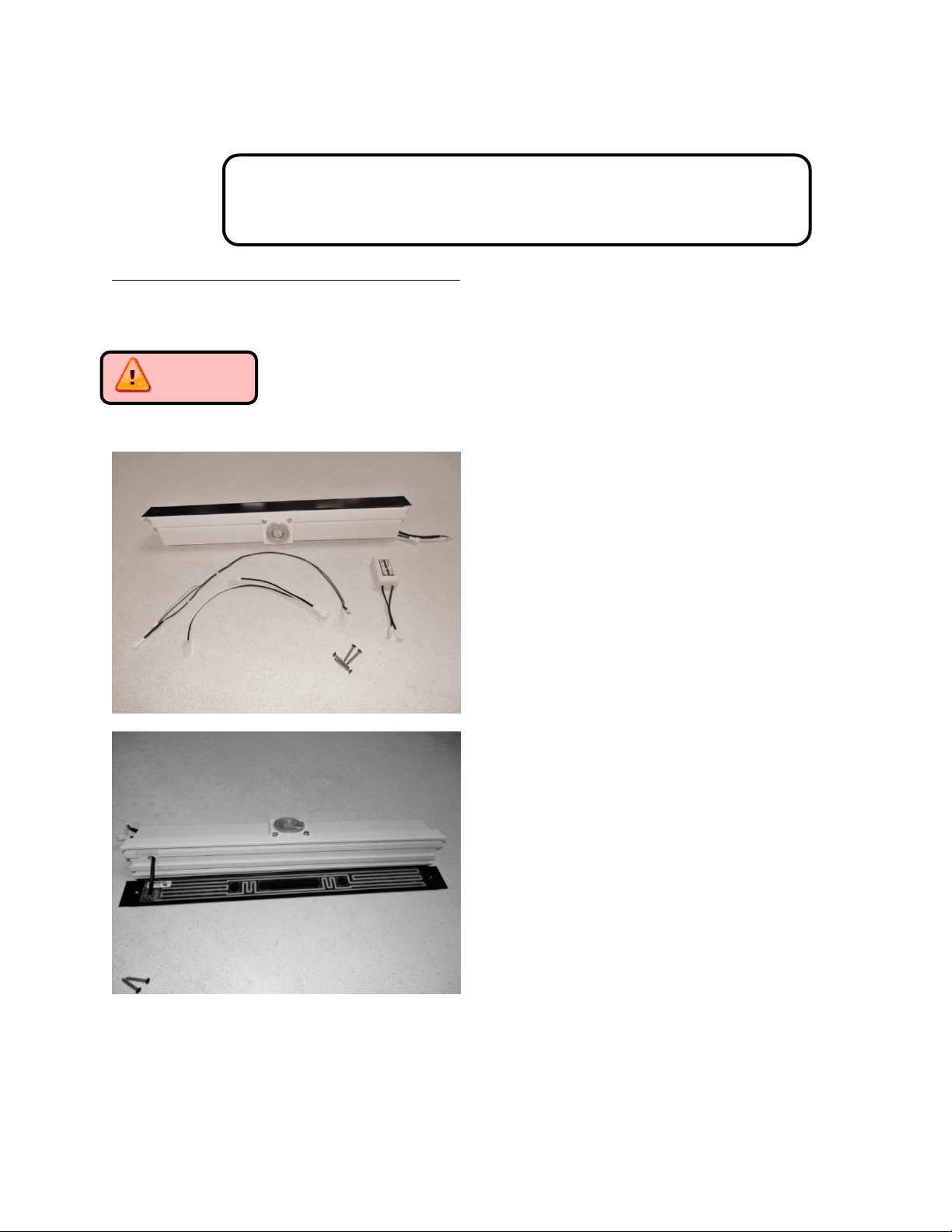
245
Section 20: Service Kits/Bulletins
20.1: Service Bulletin # 41013862
Mullion Condensation on Refrigerated Drawers
Mullion Heater Kits - Installation Instructions:
Part numbers: S42413105-BLK for Marvel models and S42418081-BLK for Marvel Professional
models (with lock).
CAUTION: The appliance must be disconnected from its power source prior to
preforming this repair.
Mullion Heater Kit components:
See page 107 for component
details.
Note the adhesive heater on rear
of painted mullion panel.
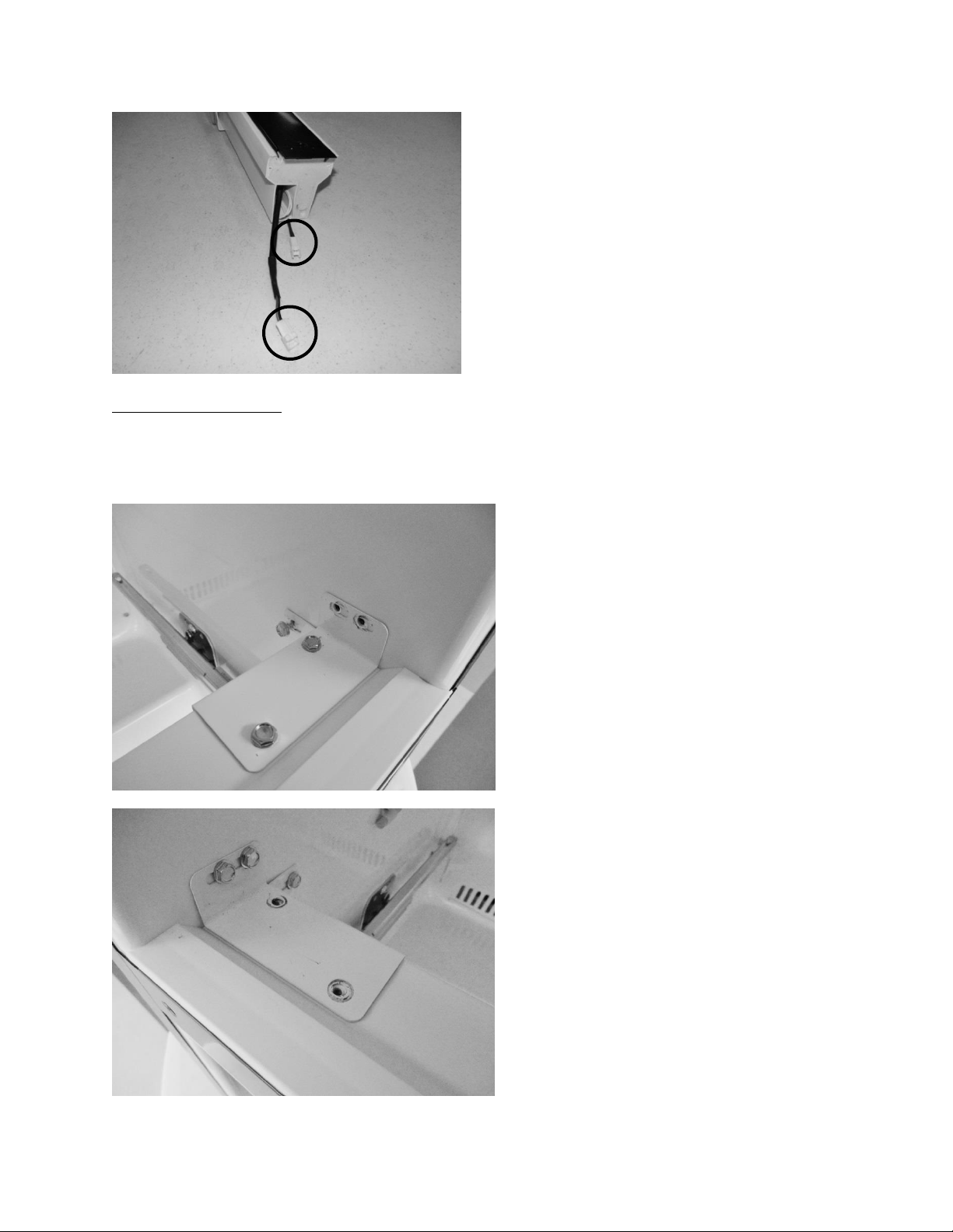
246
Accessing the Mullion
Remove the Drawers (See Section 7.3)
Remove the Mullion as follows:
Remove the two top sheet metal
screws securing the right hand
mullion bracket to the cabinet.
Loosen the rear screw. The mullion
bracket will stay with the mullion
when it is removed.
Remove the sheet metal screws
on the top and bottom of the
left hand mullion bracket. The
mullion bracket will stay
attached to the cabinet.
LED light and mullion heater
harness connections.
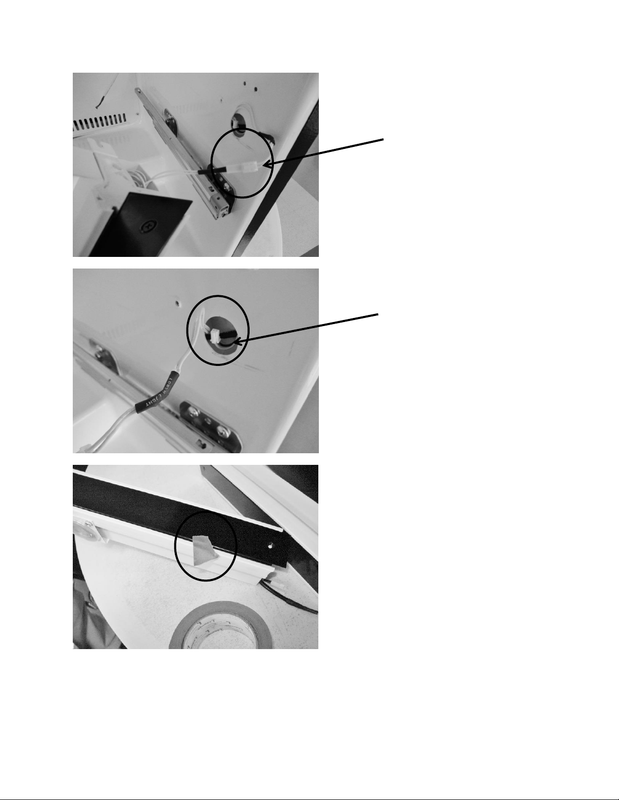
247
Pull mullion carefully away
from cabinet. Disconnect the
LED light connecter (white
wires extended from mullion to
the cabinet liner).
Pull the yellow and black
mullion heater wire out from
inside the cabinet liner.
Prior to installing the new mullion
assembly, center the black painted
strip over the plastic mullion. Use
a piece of tape on each end to
temporarily hold the assembly
together.
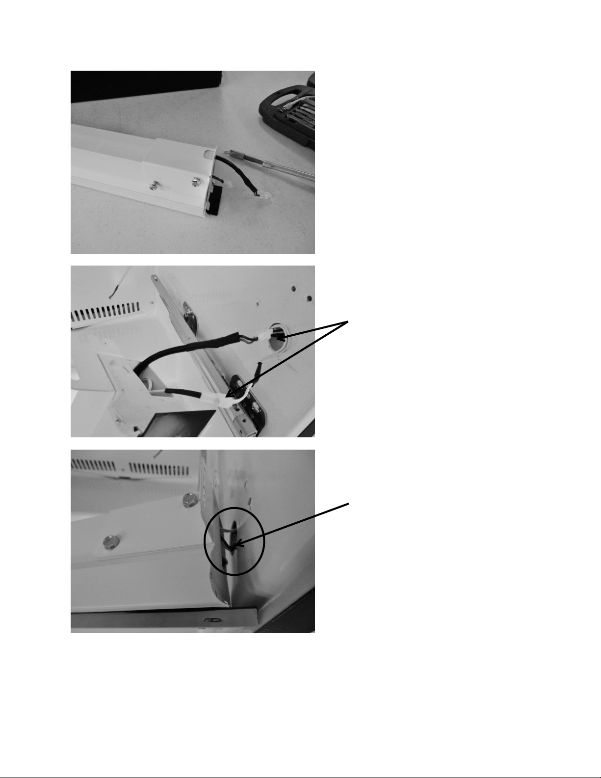
248
Attach the right hand mounting
bracket to the new mullion
assembly.
Connect both the light and heater
wires from the mullion assembly
to the wires leading from the
cabinet.
Feed the remaining light and
heater harnesses into the mullion
assembly.
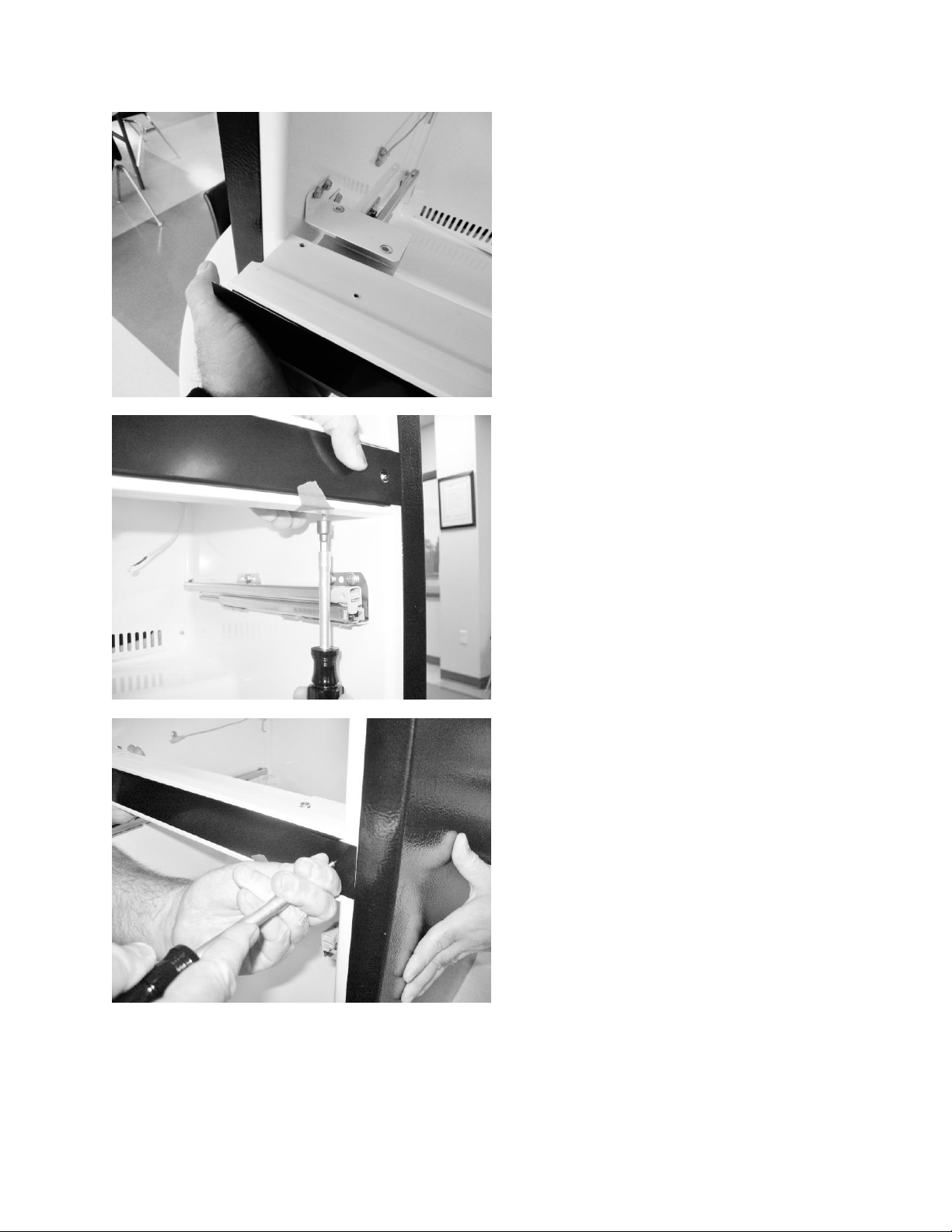
249
Carefully align both ends of the
assembly with the cabinet bracket
locations. This will fit firm. Take
care not to pinch the LED and
heater wire harness, press both
ends of the assembly into place.
Secure the mullion assembly using
the black head screws. Use one
screw on each end of mullion, the
screw will self-tap into the
assembly.
Replace all screws on each end of
the bracket and cabinet.
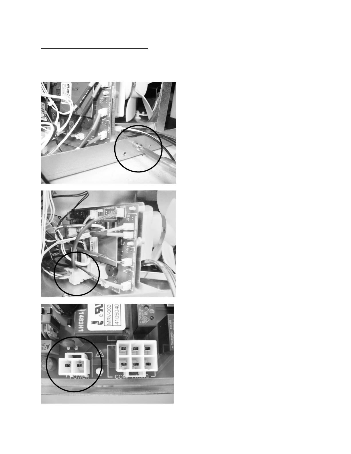
250
Accessing the Machine Compartment
Remove the lower back access panel (See Section 3.3)
Disassemble the following components as noted.
Locate and remove the Phillip’s
head screw which secures the
control board bracket to the
cabinet frame.
Disconnect the power connector
at the bottom, left rear of the
control board. See below photo
for reference.
FOR REFERENCE: Top View of
power connector on main
board.
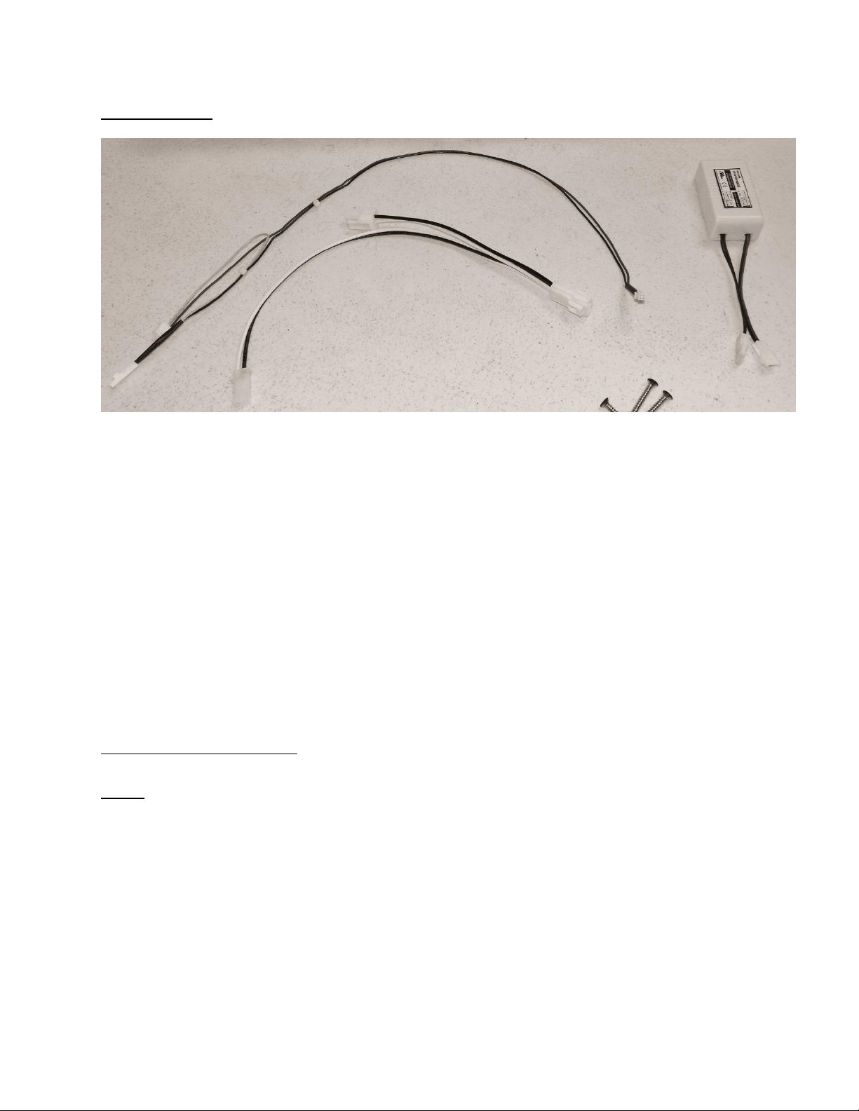
251
Kit Components
Harness A
Connector 1 (Black and White Wires)
Connector 2 (Black and White Wires)
Connector 3 (Black and White Wires)
Harness B
Connector 4 (Red and Black) power supply
Connector 5 (Yellow and Red)
Connector 6 (Black and Yellow) mullion heater
Installing the wiring harness
NOTE: Use the photo on page 8 to reference wire harness and connectors below.
1
6
5
4
3
2
Harness A
Harness B

252
NOTE: See the following photos for reference.
Wiring Harness A
1. Locate and remove the Phillip’s head screw which secures the main power board
mounting bracket to the cabinet frame.
2. Remove the power connector at the bottom, left rear of the main power board (see
above photo).
3. Plug connector “1” on harness A into the POWER terminal on the main power board.
4. Attach the original connector previously removed from the POWER terminal to
connector “2” on harness A.
5. Plug the remaining connector “3” into the adjoining terminal on the power supply
from the kit.
Wiring Harness B
1. Locate connector “4” on harness B. The wire will be identified as “Power Supply”.
Plug this connector into the remaining terminal on the power supply from the kit.
2. Locate the yellow and black harness extending through the upper, left hand corner
of the machine compartment. The connector will be marked as “Mullion Heater”.
The wire will be coiled and unplugged as seen in picture above.
3. Plug the coiled connector (step 2) into the matching yellow and black wire on
harness B, connector “6”. It is also marked as “Mullion Heater”.
4. The remaining connector “5” will be plugged into the “Aux C” terminal on the main
power board.
5. At this time, the paper can be peeled off the adhesive tape on the bottom of the
power supply. With the power supply in one hand, reach between the main power
board and the condenser fan and place the power supply in a position where it will
be out of the way. Press down on the power supply to adhere into place. The wires
can be routed over the top of the main power board.
6. Place the main power board mounting bracket back into position. Confirm that the
rear slot on the mounting bracket is secured by the positioning tab on the bottom of
the machine compartment. Take care not to pinch any wires during this step.
7. The main power board mounting bracket can now be re-secured to the cabinet
frame using the Phillip’s screw.
8. If necessary the wires can be secured together with a nylon wire tie.
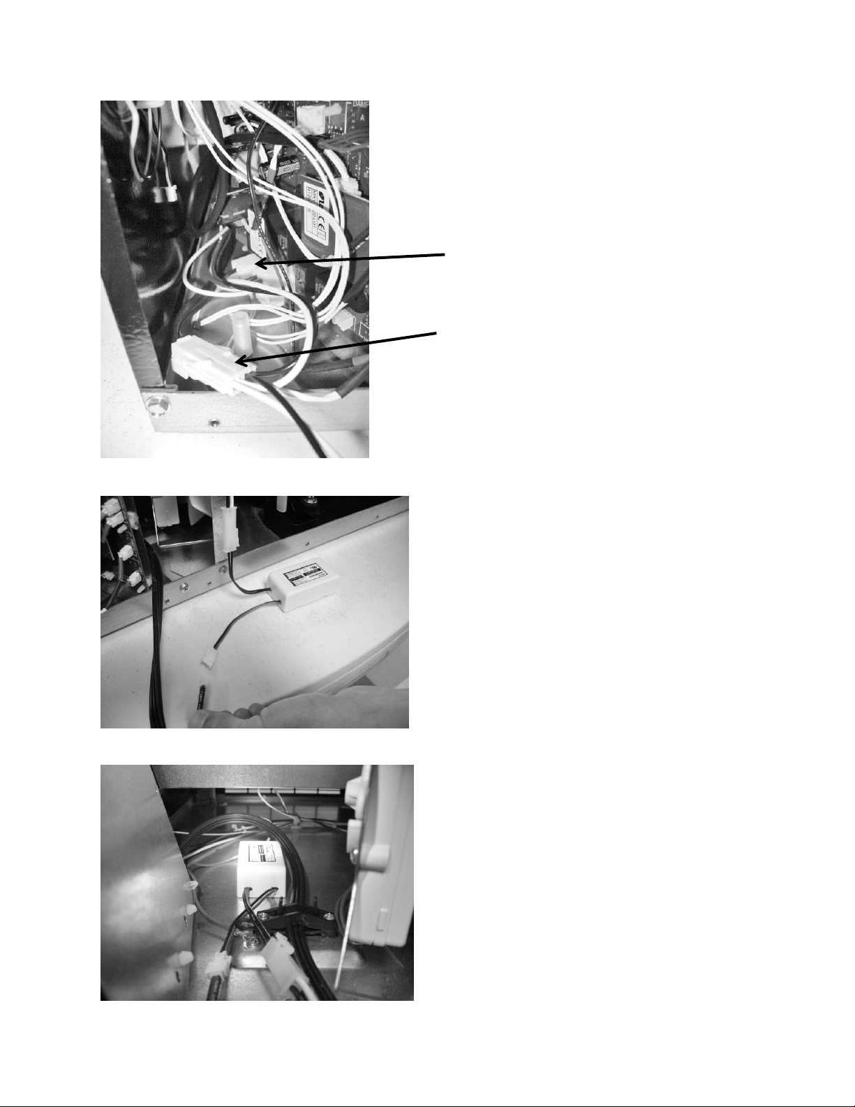
253
Connect the black and white wires
from connector 3 (harness A) and
the black and red wires from
connector 4 (harness B) to the
appropriate terminals on the
power supply.
Place the power supply between
the main power board and
condenser fan as far forward as
possible.
View of wiring harness A with
connectors “1” and “2”
Connector “1”
Connector “2”
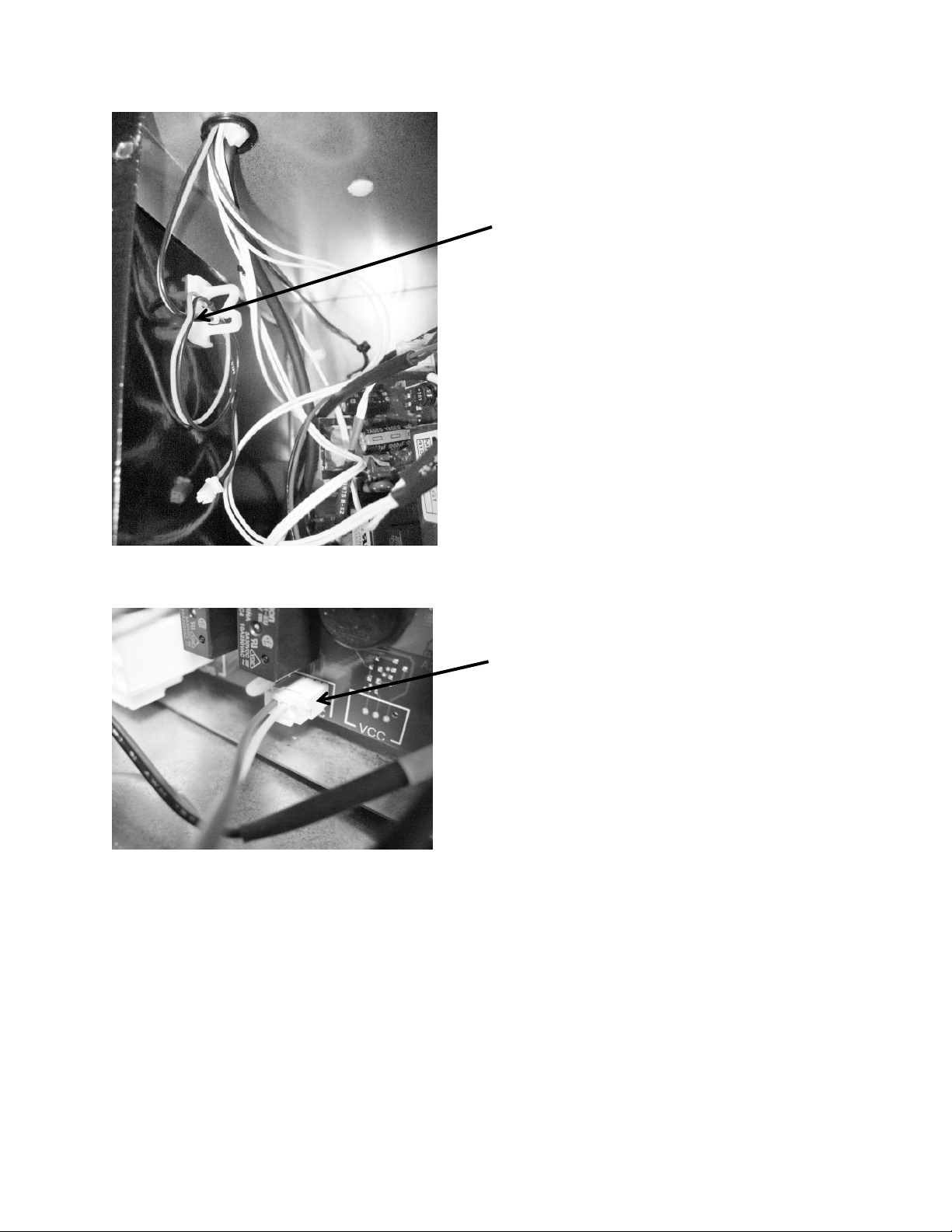
254
The rear panel and drawers can now be replaced. The unit can now be reinstalled back into
position and voltage reconnected to the unit. The mullion heater is active 100% of the time.
Note the location of the black and
yellow mullion heater harness in
the machine compartment.
The red and yellow wires at
connector 5 (harness B) will plug
into the “Aux C” terminal on the
main power board.

255
20.2: SERVICE BULLETIN # 41013861
EVAPORATOR REPLACEMENT KIT*
*THIS KIT DOES NOT FIT THE RF / RFI MODELS, SEE THAT BULLETIN LATER
IN THIS SECTION
Part number: 42249115, Evaporator Kit with Installation Instructions
REFER TO SECTION 3.6 FOR ADDITIONAL DISASSEMBLY INFORMATION
Reclaim Refrigerant from Sealed System
Reclaim the refrigerant in the sealed system per EPA regulations
Evaporator Removal
The evaporator heat exchanger is foamed in place in the back cabinet wall.
1. Cut the heat exchanger at the point it enters the foamed cabinet (behind
evaporator plate).
2. The suction line will also have to be cut at the point where it enters the foamed
cabinet from the machine compartment.
3. Remove the white foam evaporator spacers. Save as they will be used for the new
evaporator assembly.
4. Remove the evaporator and discard, caution of sharp edges from the cut tubing.
5. Unsolder suction line from compressor and discard, again use caution of sharp
edges surrounding cut heat exchanger.
6. Unsolder the liquid and capillary lines from the filter drier.
7. Drill a ½” hole in the left hand corner of the drain sump as close to the side wall as
possible. The hole must extend into the machine compartment.
8. Remove any sharp burrs on the top of the machine compartment created by the
drill bit.
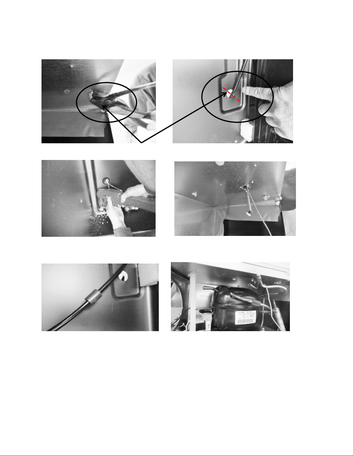
256
Cut away suction line at the above locations.
Drill a ½” hole downward into machine
compartment.
Extend new assembly through the hole.
Make sure ends are capped.
Install vibration isolator on heat exchanger
assembly behind evaporator.
Size and cut the suction tube extension to
connect the compressor to the suction line.
Top of machine compartment
Interior back wall

257
Evaporator Installation
A replacement evaporator assembly (42249115) will include the following
components:
(1) Evaporator heat exchanger assembly
(1) Filter drier
(1) Pre bent suction tube extension
(1) Vibration isolator
(2) Nylon zip tie fasteners
(2) Pieces of permagum
1. Take the replacement evaporator and unroll the capillary tube on the heat exchanger.
2. Absolutely make sure that the ends of the capillary tube and suction line are well
capped. Wrap both ends with tape to insure that no foam enters the tubing when
passing through the ½” drilled hole. Any foam that is allowed in the tubing will
compromise the sealed system.
3. Once the new evaporator is in place, the suction line in the machine compartment will
have to be bent (thumbs and forefingers) at an angle towards the compressor.
4. Carefully recoil the capillary tube.
5. Install a new filter drier and solder the capillary and liquid line in place.
6. The kit will include a section of pre-bent suction line. The bent end will be soldered into
the compressor.
7. Use a 3/8”swedging tool to expand the opposite end of the suction extension. This will
fit over the new suction line extending into the machine compartment. This connection
can now be soldered.
8. The kit also includes a rubber vibration isolator, place this onto the heat exchanger
behind the evaporator to protect against tube rattles between the evaporator and
cabinet liner.
9. Replace the defrost thermistor and attach with the two zip lock fasteners in the kit.
10. Place one piece of permagum around the newly drilled hole for the suction line
assembly inside the interior of the cabinet. Make sure that it is worked into and around
the hole to seal off any moisture or heat.
11. Use the second piece of permagum and also work that into and around the hole in the
machine compartment where the new suction line assembly exits the liner.
12. Re-install the white foam spacers. The spacers have an off center cut on one side, place
the fat side of the spacer (with the thickest foam) towards the back wall of the liner.
13. Reassemble the coil cover and interior components in reverse order as removed.
14. Prior to reassembling the machine compartment, a thorough leak check should be
performed to verify that all joints have been soldered or brazed correctly.
15. Proceed to pull a minimum 50 Micro vacuum.
16. Recharge system with weighted charge per specification on serial plate.
17. Leak check.
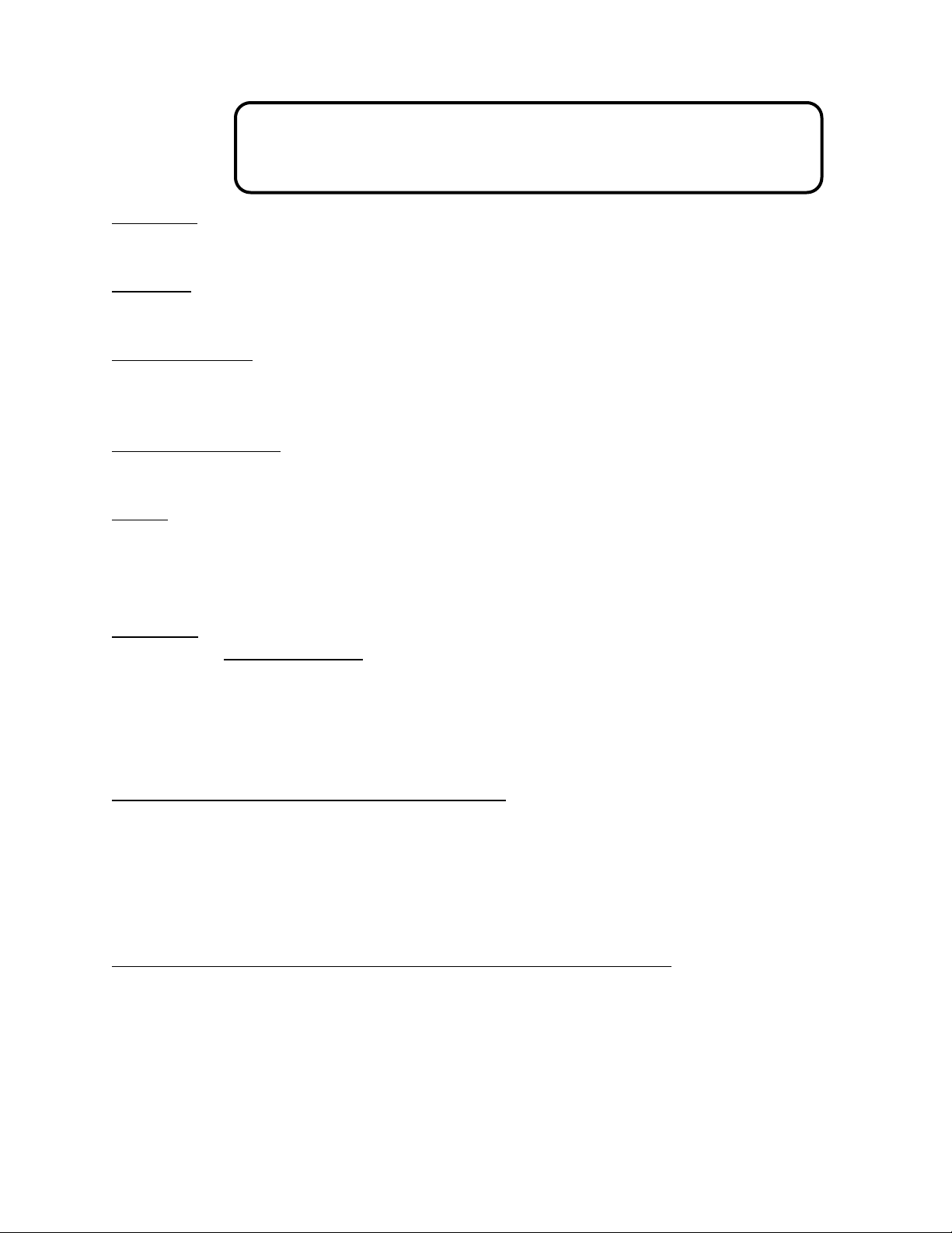
258
20.3: SERVICE BULLETIN # 41013995 Rev C
Contact between the Door and Door Sensor
Complaint: An audible door alarm sounds every 60 seconds and “Door Ajar” will continually
flash on the User Interface display pad.
Diagnosis: The door sensor and / or spacer are not closing the alarm circuit. Both components
should be replaced.
Models Impacted: Most ML and MP models built within the serial number range listed below.
Ice Machines (no door sensor) and Refrigerated Drawers are exempt. Drawer models use a
rocker style door switch.
Serial Number Range: ML and MP (Ice machines and Drawer Models not included) models built
prior to 20150109008H.
Repair: Service Kits:
S41050470-ss (stainless)
S41050470-wht (white)
S41050470-blk (black)
Service Kit:
PARTS INCLUDED:
Door sensor
Door spacer
Alcohol wipes (2)
Installation Instructions
This service kit includes the following components:
Door sensor
Door sensor spacer
Alcohol wipes (2)
Assembly Instructions 41013996-ins
These instructions consist of 5 steps. Please follow all steps in sequence.
Door sensor removal
Door sensor location
Door sensor replacement
Door spacer location
Door spacer replacement
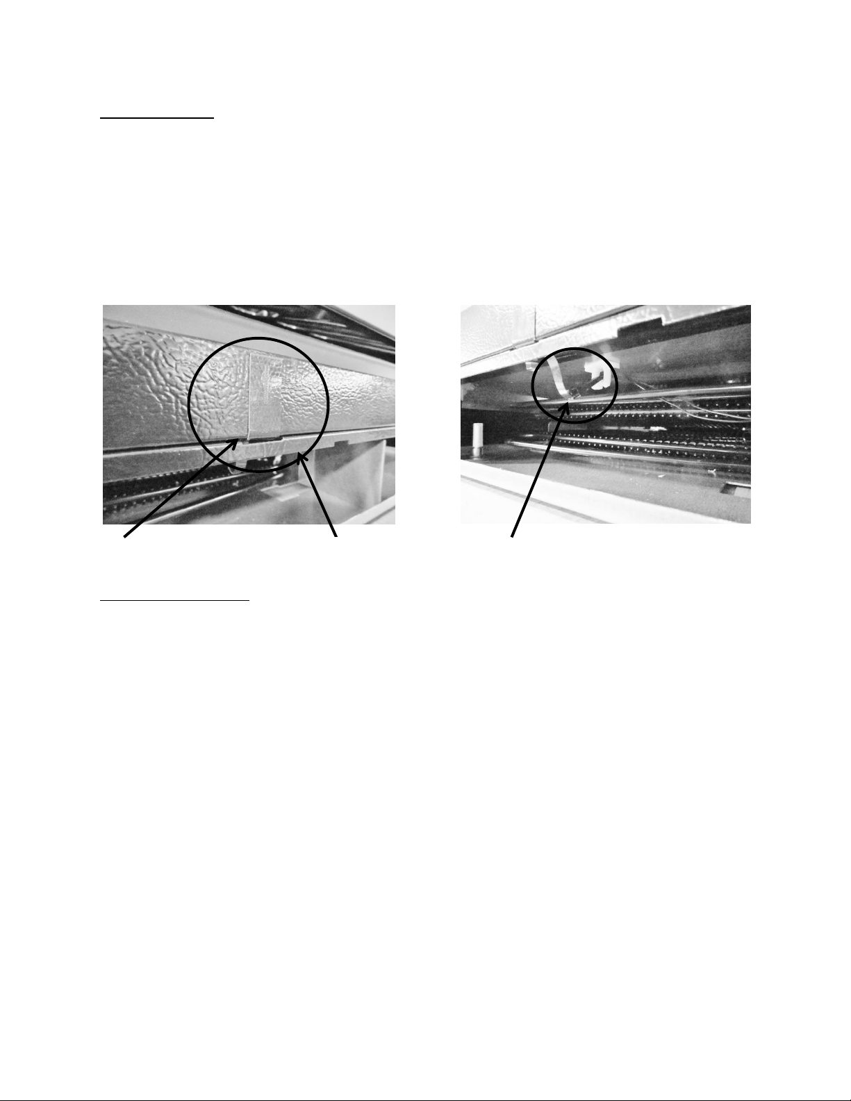
259
The Door Sensor
The door sensor is located on the bottom cabinet flange; approximately 5 ¼” away from the
inside flange of the cabinet; on the handle side of the cabinet (Exact measurement location
attached). The Refrigerated Drawers do not use this technology, dual rocker switches are used
for drawer models.
The door sensor is resistance activated by the pressure from the door gasket. Light
functionality and the door alarm are directly related to this switch.
Door Sensor Removal
1. Remove the toe grill.
2. Disconnect the door sensor at the harness terminal behind the trim piece. See photo
on page 1.
3. Remove the door sensor from the cabinet by starting in one of the upper corners and
peeling in a downward motion.
4. Once the sensor has been removed from the flange area:
a. Grasp the sensor with the right hand using the thumb and forefinger.
b. Grasp the electrical strip portion of the sensor between the thumb and
forefinger on the right hand.
5. Slowly work the sensor through the gap on the lower trim section to remove. The
upper portion of the electrical strip has some adhesive backing so care is advised.
Door Sensor location
Sensor disconnect terminal
Cabinet trim
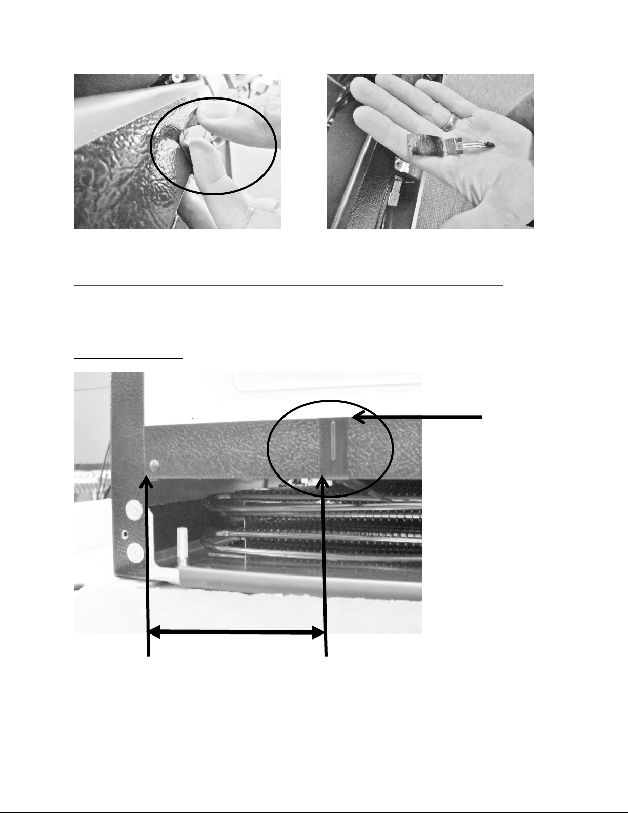
260
Prior to proceeding with the next step, please refer to the following pages on proper
placement for both the door sensor and the door spacer.
Door Sensor Location
Peel away from cabinet flange
Sensor removed
A
B
5 ¼”
C
261
Door Sensor Replacement
1. Prepare the metal surface of the cabinet flange, use the first alcohol cloth to remove any
dirt or residue from the previous sensor.
2. Do not remove the adhesive backing from sensor until it is in place.
3. Slide the new sensor into the gap between the bottom flange and trim piece.
4. Once the sensor is in place:
a. Remove the adhesive backer from sensor.
b. Ensure the sensor is in position and carefully adhere to the cabinet. Apply
carefully using thumb pressure to the outer perimeter of the door sensor.
c. NOTE: Care should be taken not to apply unnecessary pressure directly on the
raised vertical center of the sensor face. The switch is pressure sensitive; any
undue pressure could damage the sensor.
5. Replace the toe grill.
NOTE: A new door gasket with a stronger magnet was introduced into production at the end
of April 2015.
The starting Serial Number for this change was 20150421xxxH. All units produced after this
date will incorporate the new door gasket.
Anytime the above service kits (S41050470-varient) are ordered for a serial number built
prior to 20150421xxxH, a new door gasket, with stronger magnet should also be ordered.
ALWAYS LOCATE AND POSITION THE SENSOR FROM THE HANDLE SIDE OF THE
CABINET.
NOTE: Prior to removing the backing from the sensor, the surface of the cabinet
flange needs to be prepared using an alcohol wipe to remove any dirt or residue.
1) The front vertical edge of the sensor (B) is located 5 ¼” (5.25”) from the
inside of the cabinet flange (A).
2) Locate the top of the sensor along the top edge of the bottom cabinet
flange (C).
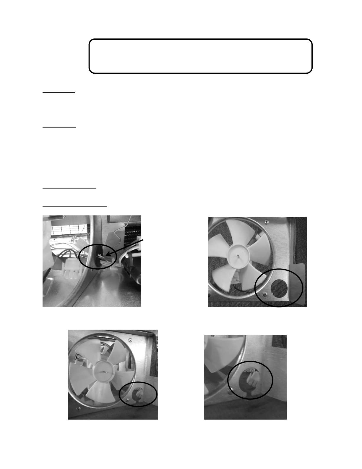
262
20.4: SERVICE BULLETIN # 41014167
Slotted Condenser Shroud
Complaint:
The condenser fan motor cannot be replaced without disconnecting all the existing
wiring passing through the hole in the fan shroud.
Correction:
The new fan shroud is slotted from the bottom of the hole in the fan shroud to the
bottom edge of the shroud surface.
To replace the fan motor, simply remove the fan shroud assembly as mentioned in
Section 4, remove the protective plastic grommet inside the diameter of the hole, tip
the shroud assembly and remove the wires from the slot.
Models Impacted: Most ML and MP models (excludes ice machines).
Serial Number Range: Production prior to 20150505033H
Wire bundle
passing through the
plastic grommet
inserted into the
condenser shroud.
Original Fan Shroud
Revised
Fan
Shroud

263
20.5: SERVICE BULLETIN # 41014168
Showroom Mode Alarm
Complaint:
Appliance sounds an audible alarm when in the showroom mode.
Diagnosis:
An audible alarm sounds every 45 seconds after an “undetermined” amount of time
once the appliance is placed in the showroom mode.
No error code will be displayed on the user interface display.
The firmware installed on the main power board has an alarm feature installed that
sounds once the appliance is placed in the showroom mode.
The firmware is not detrimental to the operation or performance of the appliance. This
alarm will not activate unless left in the showroom mode. During normal usage, the
alarm will not sound.
The error is not the fault of the user interface display. The main power board located in
the machine compartment must be replaced.
The main power board is not adjustable or reprogrammable; it must be replaced.
Models Impacted:
ML and MP (excludes ice machine) models built within the serial number range listed
below.
Serial Number Range:
All models built prior to the manufacturing date of May 18, 2015 (20150518xxxH).
Repair:
Replace the main power board (located in machine compartment). The user interface
board does not come into play with this error.

264
Service Kit:
Provide complete model and serial numbers to ensure that the main power boards are
programmed to the specific model. These boards are not field adjustable or interchangeable
between models. They are programmed model specific.
Part Numbers
o S41050480 Single Zone Appliance*
o S41050401 Dual Zone Appliance*
*Available per model type, contact customer service at 1-800-223-3900
Service Procedure:
Disconnect the appliance from the power supply.
Gain access to the machine compartment.
Disconnect wiring from the main power board.
Remove old main power board and replace with new.
Discard old board.
Return the appliance back into operation.

265
20.6: SERVICE BULLETIN # 41014169
Evaporator / Heat Exchanger Replacement
(RF and RFI Models ONLY)
Complaint:
Not getting cold
Not cold enough
Long run time
Diagnosis:
Evaporator Leak
Welded aluminum / copper seam leak
Restriction
Correction:
The evaporator heat exchanger assembly must be replaced. Refer to Section 16 for
access to the evaporator assembly.
The heat exchanger is foamed in place from the inside of the machine compartment to
the inside of the freezer compartment.
Since the original evaporator heat exchanger assembly cannot be removed, the
replacement assembly must be routed out the back of the cabinet and down into the
machine compartment to the compressor.
Models Impacted:
ML and MP models built within the serial number range listed below.
Serial Number Range:
Serial number range: All
Service Kit Number:
42249121*
* THIS KIT IS ONLY FOR RF AND RFI MODELS.
This replacement is performed similar to that described earlier in this section with the following
exception.
The heat exchanger will be run through the back wall of the cabinet (not down
through the drain section and out into the machine compartment).
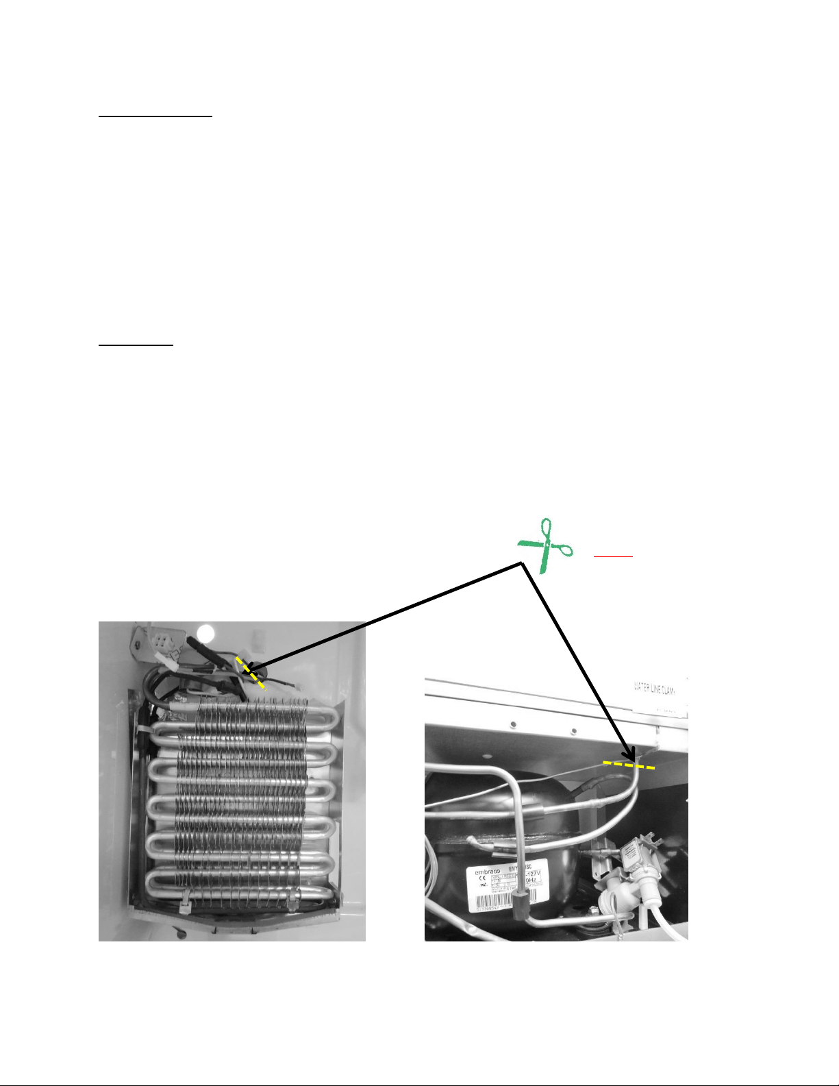
266
Kit Components:
Evaporator
Heat exchanger
Filter drier
Suction line insulation
Permagum
Suction line cover panel
3 p-clamps
12 sheet metal screws
2 aluminum defrost heater straps
Procedure:
Disconnect power to appliance.
Access evaporator compartment per Section 16.
Reclaim refrigerant.
Cut away and discard exposed evaporator and heat exchanger assemblies.
Install new evaporator assembly per the kit instructions.
Charge and leak check seal system.
Reassemble all components.
NOTE: After reclaiming the
refrigerant, the exposed
evaporator and suction line
assembly must be cut away from
the appliance and discarded.
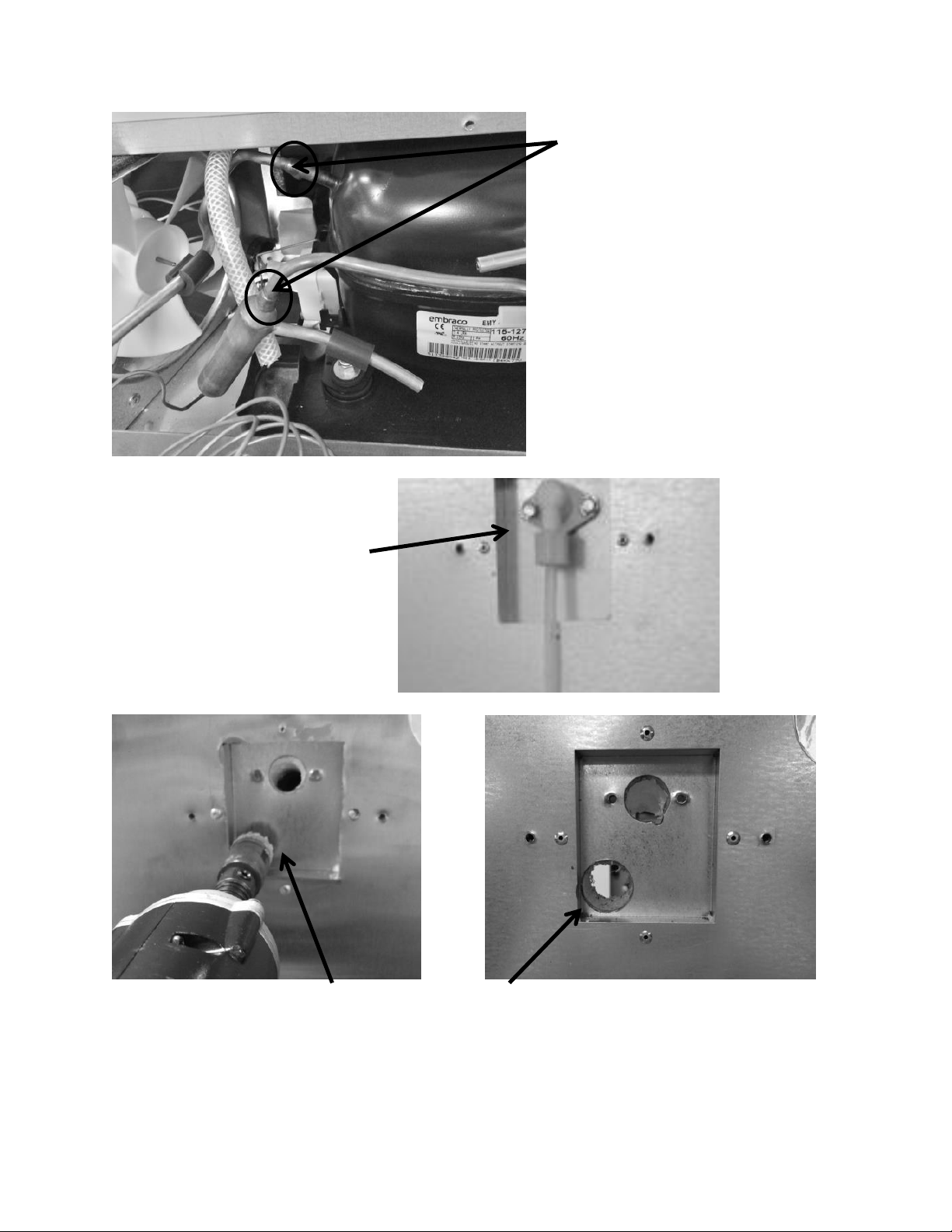
267
Un-braze the remaining suction line
and the filter drier at these joints.
Use a 1” hole saw to completely drill
through the bottom left hand corner
inside the water fill tube recess.
The location of the finished hole.
Completely remove water
fill assembly.
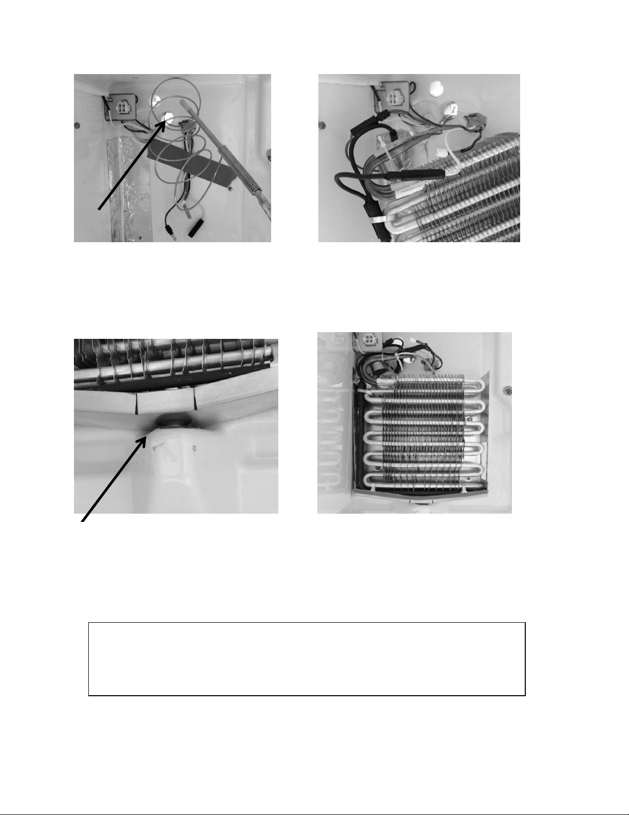
268
Feed the capillary tube and suction line of
the new evaporator assembly (inside to
the outside) through the 1” hole.
Replace heater, defrost termination
thermostat, and zip tie the thermistor to
the evaporator.
Make certain that the drip pan drain fits
snuggly into the drain tube.
Install the 2 drain pan screws to secure
the evaporator assembly. REMEMBER to
stuff permagum into the 1” hole drilled
for the heat exchanger.
Insert the Insulation Tube over the suction tube / capillary assembly and zip tie in place.
The capillary tube on the bottom end can now be coiled and zip tied after determining
the length needed for installing into the filter drier.
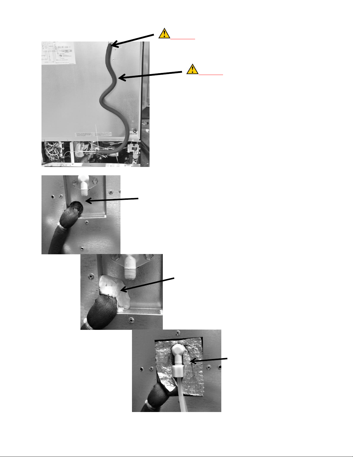
269
CAUTION: DO NOT CUT. It is
critical not to eliminate any tubing
length. This is necessary to eliminate
the possibility of excessive evaporator
feed noise. The entire length of
suction/capillary tubing supplied with
the assembly must be used. Route the
tubing down the outside back wall
similar to the picture.
Reinstall the fill tube and secure.
Fill the 1” hole with the stuffer plug
provided; make sure that the foam
insulator tube is tucked completely
inside the 1” hole.
Apply permagum as shown.
Reinstall the water line.
Install foam insulation pad as shown.
CAUTION: This bend must be made with caution to
prevent collapsing, pinching, or restricting the tubing radius.
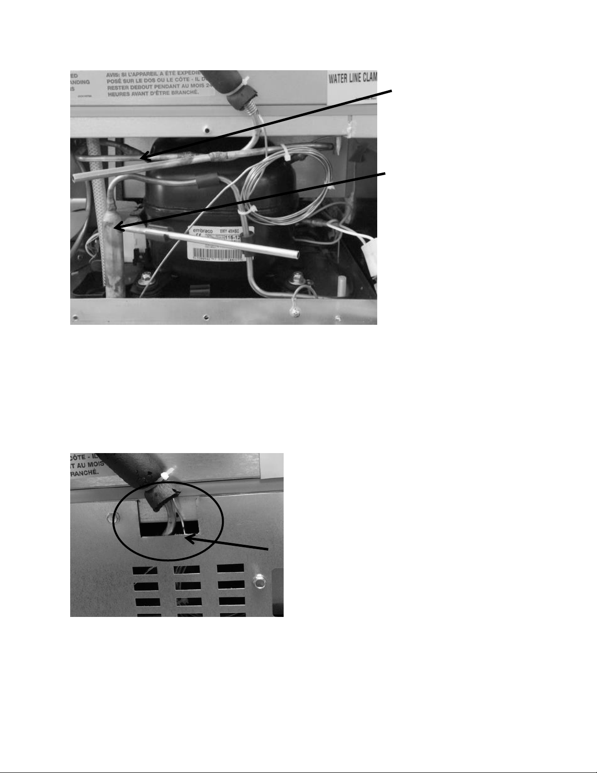
270
Notch out a clearance hole
on the rear access panel to
accommodate the suction
line and capillary tube.
Install and braze the ¼”
suction line extension
(jumper tube) into the
compressor and new
suction line.
Install and braze the filter
drier.
Once the tubing has been brazed and the system closed; pull a vacuum, leak check, and weigh charge
per the specified amount on the serial plate.
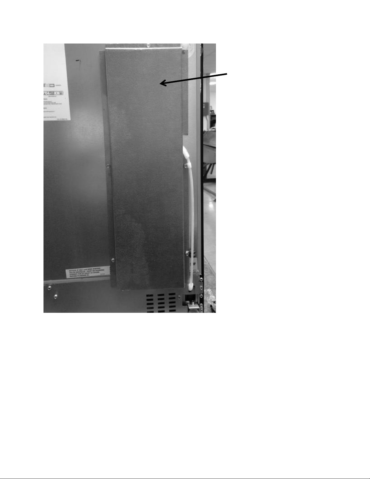
271
Attach the back cover and return
to operation.
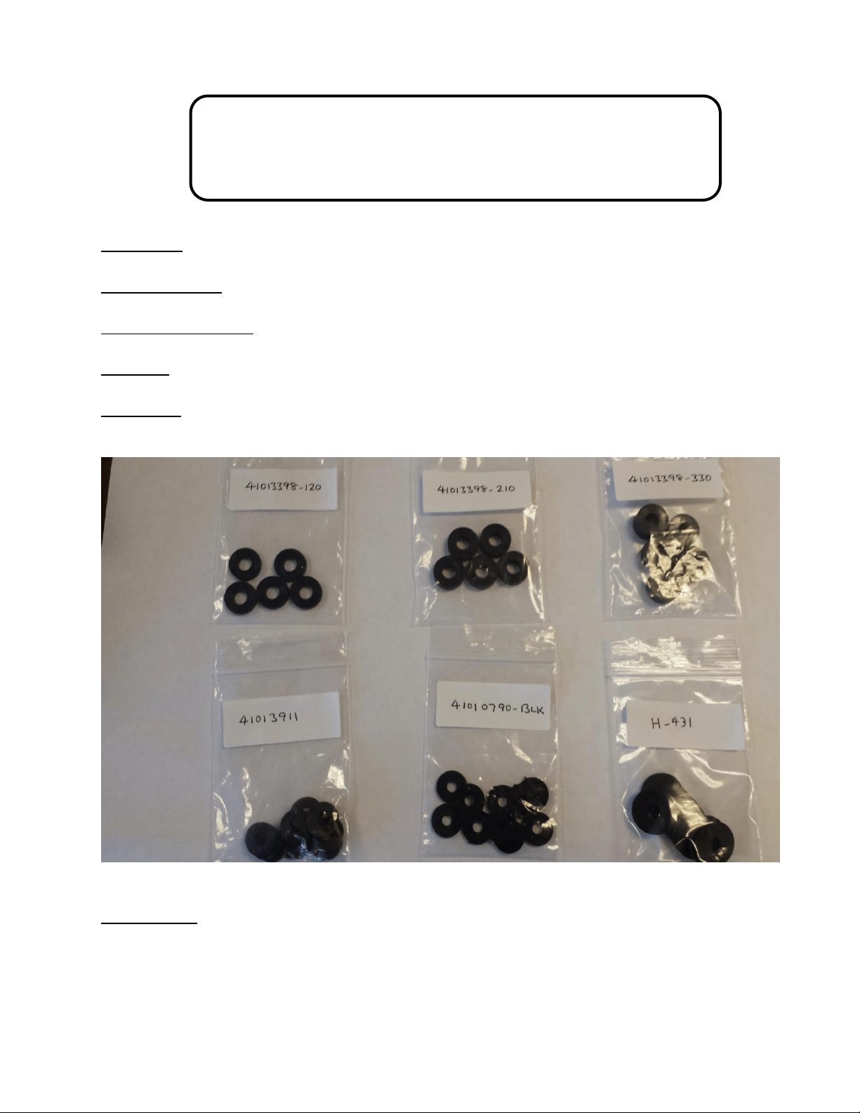
272
20.7: SERVICE BULLETIN # 41014241
Shelf Shim Kit
(Non-Professional Models)
Service Kit: 42249228
Models Affected: All non-professional models
Serial Number Range: All
Contents: 6 washer packages of assorted thicknesses and density.
Application: Shim kit to correct shelving falling out of support track due to dimensional
variances.
Tools Needed:
#2 Phillips screwdriver
Slipjoint pliers
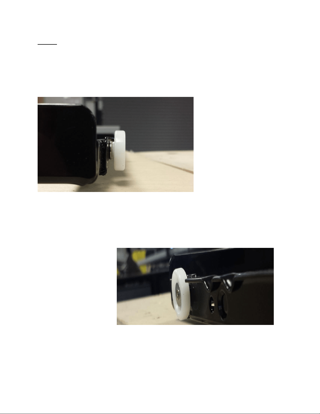
273
Step #1:
Check that the shelf rollers are not bent. Shelf rollers should be parallel to the shelf rail. If a
roller is bent, use pliers to bend the roller back to the correct position and check to see if shelf
still falls out of rail.
These photos show the correct orientation of
the shelf roller. They should be in a vertical
upright position without appearing at an angle.
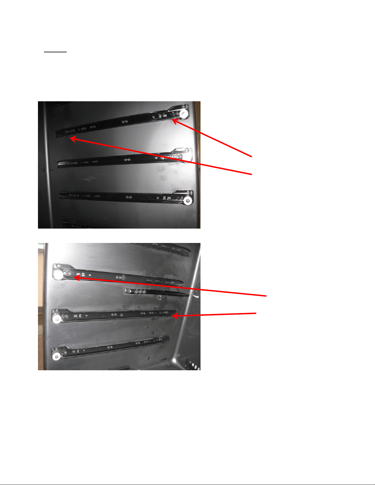
274
Step #2:
If shelf still falls out of rail, confirm that the shelf shims in use are correct per the following,
correct if necessary, and re-check shelf support.
0.330” - [Front]
0.210” - [Rear]
Hinge-Side Full-Shelf
Handle-Side Full-Shelf
0.12” - [Front]
No Shim - [Rear]

275
Step #3:
If shelving still falls out of support, add additional shim(s) as necessary. Kit includes 0.09” hard
plastic and 0.090” & 0.060” rubber shims for this step.
First, add 0.090” hard plastic shims at front and rear of the handle side. If shelving
continues to fall out, add another 0.09” shim to front and rear as appropriate.
If use of 0.090” hard plastic shim makes shelf fit too tight, (no longer rolls freely in &
out), use of a 0.090” or 0.060” rubber shim may be used. Because this rubber shim is
compliant, the mounting screw can be used to compress the shim for fine-tuning.
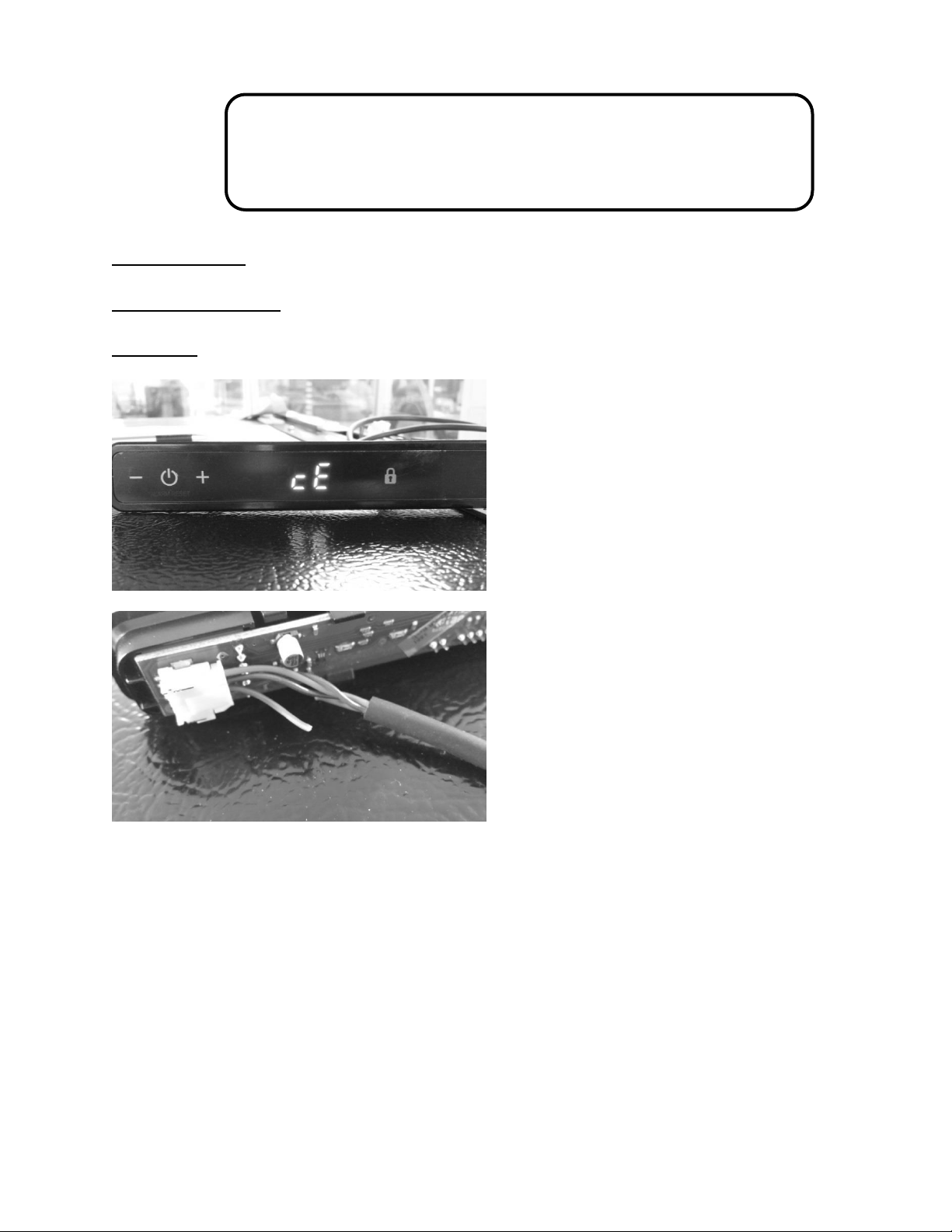
276
20.8: Service Bulletin # 41014242
Miscellaneous Control Communication Errors
Models Affected: All
Serial Number Range: All
Complaint: Unidentifable errors seen on the User Interface display.
Other possible errors are:
1. A simutaniously flashing VAC and (dash) –
2. A flashing (dash) –
3. The display showing 00 with a flashing Power Failure
The above three errors are caused by some degree of either loose, broken, or shorted wiring in
the communication cable.
Communication cables are foamed inside both the door and the cabinet. A broken wire inside
either the door or cabinet can not be repaired.
The photos to the left show a
definite communication error (cE),
the result of this was a broken
brown wire in the cable itself. This
can occur inside a connector at
the user interface, the bottom of
the door, the main control board,
or a broken wire anywhere in the
cable itself.

277
20.9: Service Bulletin # 41014243
Replacement of MP Door Skins
Replacement of a Marvel Professional Model Door Skin (caused by damage)
Models Affected: All
Serial Number Range: All
Tools Needed:
Phillips screwdriver
3/32: hex (allen) wrench
Lift up on the left hand side of the
user interface display. Once the
display is unseated, raise it high
enough from the door boot to
disconnect the wire harness.
Turn the user interface over, press
the disconnect lock and separate
the display from the wire harness.
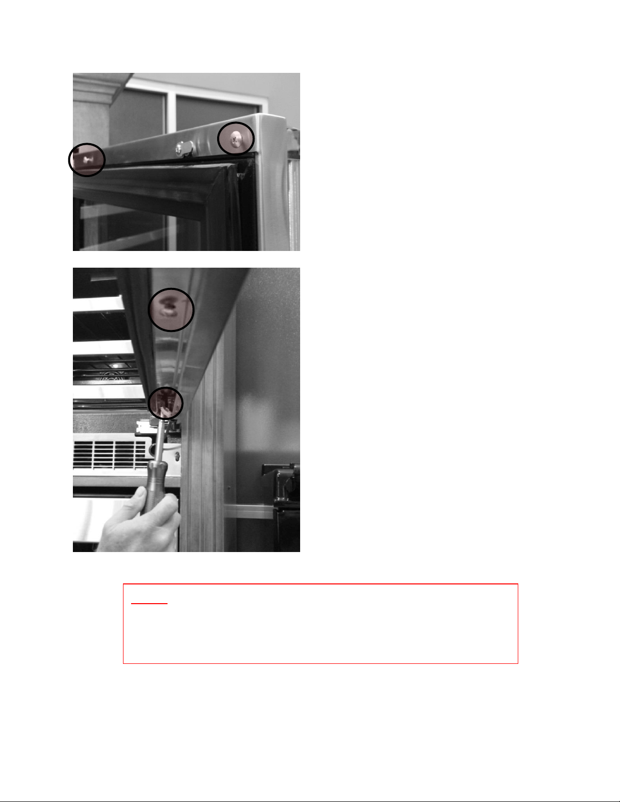
278
Remove the two Phillips screws on
the top inside of the door frame.
Remove the two Phillips screws on the
bottom inside of the door frame.
NOTE: Now that the door skin has been loosened, the side of the
door skin may want to grab and hold onto the hinge side of the
door. CAREFULLY and gradually work free.
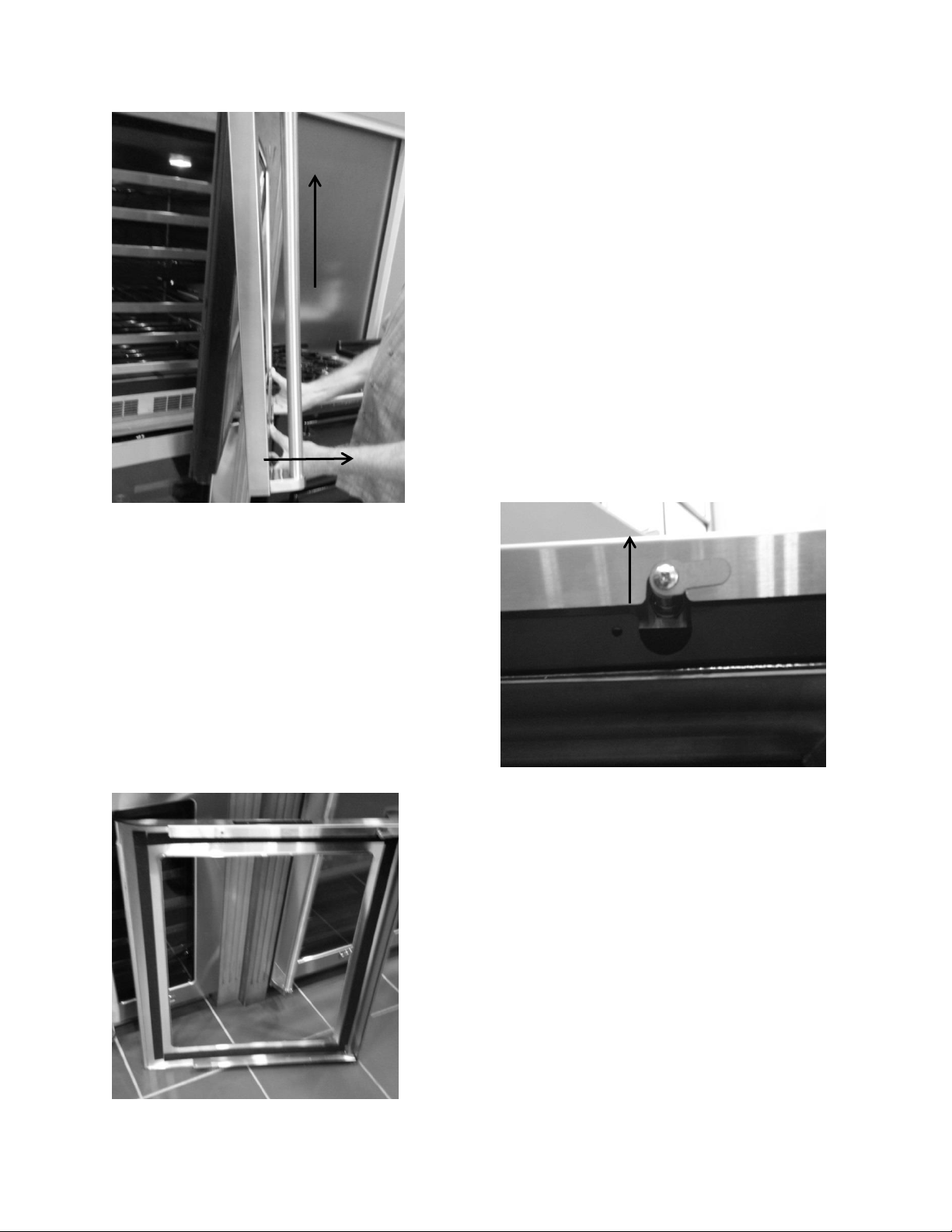
279
1. Grasp the bottom of the door skin
and pull forward away from the
door.
2. Carefully lift upward so the user
interface harness can be removed.
1
2
Continue to lift the door skin from the
top of the door. The lock assembly will
be removed with the door skin.
The handles will have to be removed and
transferred to the new door assembly.
Reassemble the door skin to the door in
reverse order that it was removed.

280
Section 21: AGA Marvel Customer Service
TECHNICAL SERVICE: 1-800-223-3900*
PART ORDERS: 1-800-223-3900*
(*Follow the phone queue to reach the correction extension)
Marvel Service Documentation:
www.marvelservice.com
Contact: 1-800-223-3900 if you do not already have a password to access the web
site.
Documentation includes:
Owners Guides
Installation Literature
Part Instructions
Parts Manuals
Service Bulletins
Diagnostic Flow Charts
Control Operational Instructions
Office Hours: Monday through Friday 8:00 AM – 5:00 PM EST
www.marvelrefrigeration.com

NOTES
281

NOTES
282