Loading ...
Loading ...
Loading ...
4
WSM3300
METHOD 2 - See Figure 2
If a separate, dedicated discharge is not possible as in Method
1, the Back-Up DC Pump can be tied into the AC-operated
pump’s discharge pipe by installing a “Y” or "T" connector.
Two check valves will be required.
1. Locate the Back-Up DC Pump on a solid, level surface in the
sump pit. Do not place the pump on a loose or sandy surface.
Small stones or sand may damage the pump resulting in
pump failure.
2. This pump has a 1-1/2 in. NPT discharge. If a 1-1/4 in.
discharge pipe is desired, an adapter (sold separately, part
#66002-WYN1 WAYNE adapter or equivalent) will be
necessary. Smaller diameter piping will reduce pump
flow-rate and performance.
3. A check valve will be required in the discharge line of both
the Main AC pump and the Back-Up DC pump to prevent
recirculation of water into the sump pit. System will not
function without two check valves.
4. Cut a 4 ft. section of 1-1/4 in. or 1-1/2 in. diameter rigid PVC
pipe. Cement 1-1/2 in. pipe to a threaded fitting. Cement
1-1/4 in. pipe into pipe coupling. Attach 1-1/4 in. pipe
section to the Back-Up DC Pump discharge adapter.
5. Screw into pump discharge.
6. Place the pump with the 4 ft. section of PVC pipe on the
sump floor or on an elevated surface if required.
7. Attach a rubber check valve (sold separately) to the top of
the discharge pipe. This will allow the pump or check valve
to be removed easily for servicing.
8. Duplicate the discharge piping arrangement for the primary
AC pump if the existing discharge line has to be adjusted to
accommodate a second pump.
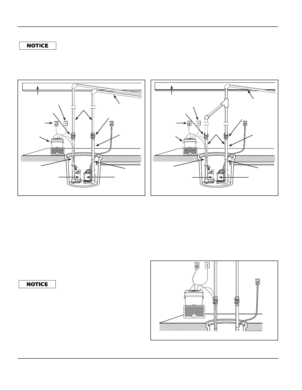
Figure 1 - Method 1 (Preferred Installation)
Do NOT strip or cross thread plastic
fittings or check valves. Flex hose is NOT
recommended. Rigid PVC or metal pipe is required for permanent installation.
9. Glue a 45º elbow to the short pipe on the Back-Up DC
Pump. Glue a “Y” adapter to the short pipe on the existing
pump, as shown in illustration for Method 2.
10. Glue a short piece of PVC pipe between the 45º elbow and the
“Y”.
The remainder of the discharge pipe installation will vary
depending on individual circumstances. Using sound plumbing
practices, route the discharge pipe to an exterior wall by the
shortest distance
.
METHODS 1 AND 2
Install float switch at least 10 in. -12 in. above bottom of sump
pit so that back-up unit turns on only when the water level is
higher than the normal “on” level for main pump. Make sure
power wires and hose clamp ends do not interfere with float
switch, pump inlet, or main pump operation. The back-up
pump must not be allowed to run dry except during the 20
second "auto-test. Incoming water can not flow directly onto
the float switch. Failure to position properly may cause improper
operation. Position the float switch so that it will not interfere
with any portion of the plumbing, wiring, or sump pit. Check for
clearance by lifting both floats.
Figure 2 - Method 2 (Alternate Installation)
Floor Joist
Rigid
PVC
Pipe
Transformer
Check Valve
Check Valve
Primary Pump
Back-Up DC Pump
1-1/4 in.
or
1-1/2 in.
PVC Pipe
Slope Pipe Down
Floor Joist
Rigid
PVC
Pipe
Transformer
Check Valve
Check Valve
Primary Pump
1-1/4 in.
or
1-1/2 in.
PVC Pipe
Slope Pipe Down
Phone Jack
Phone Jack
12 Volt
Advanced
Notification
System
12 Volt
Advanced
Notification
System
Back-Up DC Pump
Operating Instructions and Parts Manual
Figure 3 - 12 Volt Advanced Notification System elevated
Zip Tie
Zip Tie
Zip Tie
Zip Tie
Check valves MUST be installed in the
discharge line of both the main AC pump and
the back-up DC pump. Failure to install the check valves MAY allow
water to recirculate into the sump pit. See Figures 1 and 2.
www.waynepumps.com
Loading ...
Loading ...
Loading ...