Operator's Manual
®
CRRFTZMRN
32cc 2-Cycle Engine
17 Inch Cutting Path / .080 In. Line
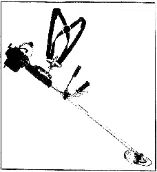
GASOLINE BRUSHWACKER ®
Model No.
358.795050
DANGER:
Read and follow all Safety Rules and Operating
Instructions before first use of this product.
I_ For answers to Your questionsabout this product:
Call 7 am-7 pm, Mon--Sat; Sun, 10 am-7 pm
• 1-800-235-5878 (.o,,_.,,=._._o.._.)
Se_IYs,Roebuck and Co., Hoffman Estates, IL 60179 USA
530-087633 08/17/98
Warranty Statement 2 Storage 15
Safety Rules 2 Troubleshooting Chart 16
Assembly _ ..... 5 Parts List 20
Operation 8
Maintenance 12 Spanish 23
Sewice & Adjustments 13 Parts and Ordering Back
FULL ONE YEAR WARRANTY ON CRAFTSMAN GAS POWERED
BRUSHWACKER ® BLADED TRIMMER.
For one year from the date of purchase, when thisCraftsman Gas Powered
Brushwackeris maintained, lubricatedand tuned upaccordingto the operating
and maintenance instructionsinthe Operator's Manual, Sears willrepair,free of
charge, any defect in materials orworkmanship.
This warranty excludes the blade, nylonline, sparkplug, and airfilter, which are
expendable parts and become wom duringnormaluse.
Ifthis Brushwacker isused forcommercial purposes,thiswarranty appliesfor only
90 days from the date of purchase. IfthisBrushwackerisusedfor rentalpurposes,
this warranty appliesfor only30 days from the date ofpurchase. Thiswarranty ap-
plies onlywhile this productisin use in the United States.
WARRANTY SERVICE IS AVAILABLE BY RETURNING THE BRUSHWACKER
TO THE NEAREST SEARS SERVICE CENTER IN THE UNITED STATES.
This warranty gives you specific legal rights,and you may also have other rights
whichvary from state to state.
Sears, Roebuck and Co., D/817 WA Hoffman Estates, IL 60179
DANGER: This power tool can be
dangerous!This unitcancause serious
injuryincludingamputationor blindness
to the operatorand others.The warn-
ingsand safety instructionsin thisman-
ual mustbe followedto providemason-
able safety and efficiencyin usingthe
unit.3"beeperator is responsiblefor fol-
lowingthewamings and instructionsin
this manualand on the unit.Read the
entireOperator'sManual beforeassern-
blingand usingthe unit!Restricttheuse
of this unitto personswho read,under-
stand,and followthe warningsand in-
structions in thismanual and on the unit.
Never allowchildrento usethis uniL
WARNII_G: Follow all wamings and
instructions. Failure to do so can result
in sedous injury.
SAFETY NOTICE
Exposure to vibrations through pro-
longed use of gasoline powered hand
tools could cause blood vessel or
nerve damage in the fingers, hands,
and joints of people prone to circula-
tion disorders or abnormal swellings.
Prolonged use in cold weather has
been linked to blood vessel damage in
otherwise healthy people. If symptoms
occur such as numbness, pain, lose of
strength, change in skin color or tex-
ture, or loss of feeling in the fingers,
hands or joints, discontinue the use of
this tool and seek medical attention.
An anti-vibration system does not
guarantee the avoidance of these
problems. Users who operate power
tools on a continual and regular basis
must monitor closely their physical
condition and the condition of this tool.
2
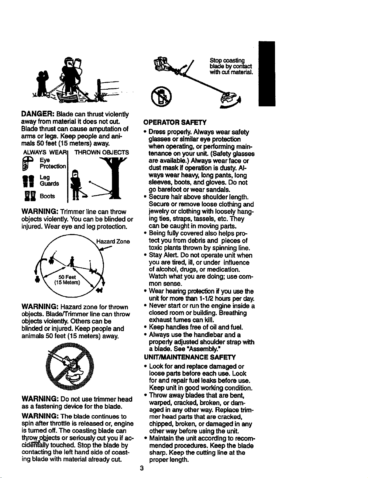
DANGER: Bladecanthrustviolently
awayfrommaterialit doesnotcut.
Bladethrustcancause amputation of
arms or legs. Keep people and ani-
mals 50 feet (15 meters) away.
ALWAYS WEAR
I
Leg J
Guards I •
U BootaI
WARNING: Trimmer line can throw
objects violently. You can be blinded or
injured. Wear eye and leg protection.
HazardZone
WARNING: Hazard zone for thrown
objects. Blade/Trimmer line can throw
objects violently. Others can be
blinded or injured. Keep people and
animals 50 feet (15 meters) away.
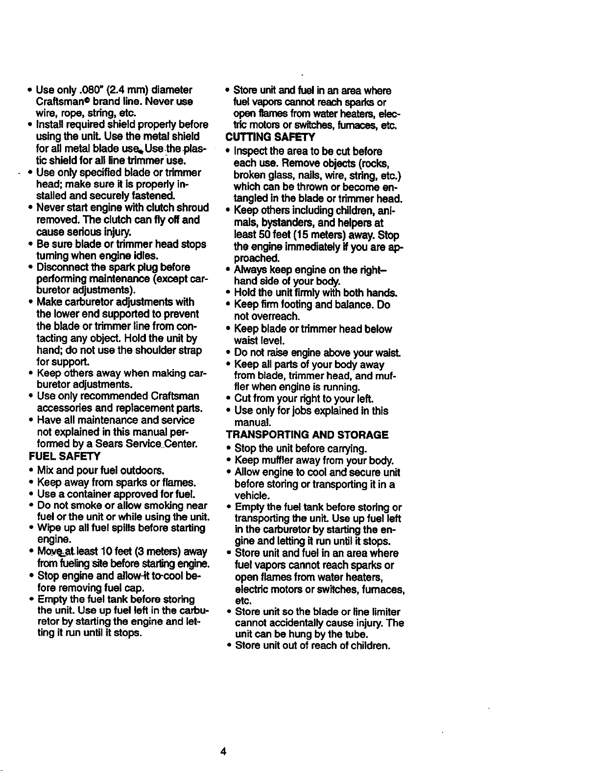
WARNING: Do not use trimmer head
as a fastening device for the blade.
WARNING: The blade continues to
spin after throttle is released or, engine
is turned off. The coasting blade can
throw obiects or seriously cut you if ac-
ciden-fft-allytouched. Stop the blade by
contacting the left hand side of coast-
ing blade with material already cut.
tiSt_ coas_ng
• bycontact
with cutmaterial
®
OPERATOR SAFETY
• Dress properly. Always wear safety
glasses or similar eye protection
when operating, or performing main-
tenance on your unR. (Safety glasses
are available.) Always wear face or
dust mask if operation is dusty. Al-
ways wear heavy, long pants, long
sleeves, boots, and gloves. Do not
go barefoot or wear sanda/s.
• Secure hair above shoulder length.
Secure or remove loose clothing and
jewelry or clothing with loosely hang-
ing ties, straps, tassels, etc. They
can be caught in moving parts.
• Being fully covered also helps pro-
tect you from debris and pieces of
toxic plants thrown by spinning line.
• Stay Alert. Do not operate unit when
you are tired, ill, or under influence
of alcohol, drugs, or medication.
Watch what you are doing; usa com-
mon sense.
• Wear hearing protection if you use the
unitfor more than 1-1/2 hours per day.
• Never start or run the engine inside a
closed room or building. Breathing
exhaust fumes can kill.
• Keep handles free of oil and fuel.
• Always usa the handlebar and a
properly adjusted shoulder strap with
a blade. See "Assembly."
UNIT/MAINTENANCE SAFETY
• Look for and replace damaged or
loose parts before each usa. Look
for and repair fuel leaks before usa.
Keep unit in good working condition.
• Throw away blades that are bent,
warped, cracked, broken, or dam-
aged in any other way. Replace trim-
mer head parts that are cracked,
chipped, broken, or damaged in any
other way before using the unit.
• Maintain the unit according to recom-
mended procedures. Keep the blade
sharp. Keep the cutting line at the
proper length.
3
• Use only .080" (2.4 ram) diameter
Craftsman © brand line. Never use
wire, rope, stdng, etc.
• Install required shield properly before
using the uniL Use the metal shield
for all metal blade use. Usethe plas-
tic shield for all line trimmer-use.
- • Use only specified blade or tdmmer
head; make sure it is properly in-
stalled and securely fastened,
* Never start engine with clutch shroud
removed. The clutch can fly off and
cause serious injury.
• Be sure blade or tdmmer head stops
turning when engine idles,
• Disconnect the spark plug before
performing maintenance (except car-
buretor adjustments).
• Make carburetor adjustments with
the lower end supported to prevent
the blade or trimmer line from con-
tacting any object. Hold the unit by
hand; do not use the shoulder strap
for support.
• Keep others away when making car-
buretor adjustments.
• Use only recommended Craftsman
accessories and replacement parts.
• Have all maintenance and service
not explained in this manual per-
formed by a Sears Service_Center.
FUEL SAFETY
• Mix and pour fuel outdoors.
• Keep away from sparks or flames.
• Use a container approved for fuel.
• Do not smoke or allow smoking near
fuel or the unit or while using the unit.
• Wipe up all fuel spills before starting
engine.
• Moye,r_at-least 10 feet (3 meters) away
from fueling site before starling engine.
• Stop engine and allow-it to-cool be-
fore removing fuel cap.
• Empty the fuel tank before storing
the unit. Use up fuel left in the carbu-
retor by starting the engine and let-
ting it run until it stops.
• Storeunitandfuel in an area where
fuel vaporscannotreachsparksor
openflames from water heaters,elec-
tricmotorsor switches,furnaces, etc.
CUTTING SAFETY
• Inspectthe area to be cut before
each use. Remove objects (rocks,
brokenglass, nails,wire, string, etc.)
whichcan be thrownor become en-
tangled inthe blade or trimmerhead.
• Keep othersincludingchildren,ani-
mals, bystanders,and helpersat
least 50 feet (15 meters) away. Stop
the engineimmediatelyif you are ap-
proached.
• Always keep engine onthe right-
hand side of yourbody.
• Holdthe unitfirmly withboth hands.
• Keep firmfootingand balance. Do
notoverreach.
• Keep blade or trimmerhead below
waist level.
• Do notraiseengineaboveyourwaist.
• Keep all pads ofyour body away
from blade, trimmerhead, and muf-
flerwhen engine is running.
• Cut fromyour righttoyour left.
• Use onlyforjobs explainedin this
manual.
TRANSPORTING AND STORAGE
• Stopthe unitbefore carrying.
• Keep muffleraway fromyourbody.
• Allowengine tocool and secure unit
before storing ortransportingitin a
vehicle.
• Emptythe fuel tank before storingor
transportingthe unit. Use upfuel left
in the carburetor by startingthe en-
gine and lettingit run untilitstops.
• Store unitand fuel in an area where
fuel vapors cannot roachsparks or
open flamesfrom water heaters,
electdcmotors orswitches,fumaces,
etc.
• Store unitsothe blade or line limiter
cannot accidentallycause injury.The
unitcan be hung bythe tube.
• Store unitout ofreach of children.
4
CARTON CONTENTS
Check carton contents against the fol-
lowing list. _ .....
Model: 358,795050
• Brushcutter
• Handlebar screws (2)
• Blade shield screws (4)
• Cupped washer
• Large nut for installing blade
• Long hex wrench
• Short hex wrench
• Bracket cover
• Metal shield
• Plastic shield
• Shoulder strap with waming
• Weed blade
• Trimmer head
• Handlebar
• Container of oil
Examine parts for damage. Do not use
damaged parts.
NOTE: If you need assistance or find
that parts are missing or damaged, call
1-800-235-5878,
Itisnormal for the fuel filter to rattle in the
empty fuel tank.
Finding fuel or oil residue on muffler is
normal due to carburetor adjustments
and testing done by the manufacturer.
ASSEMBLY
WARNING: If received assembled, re-
_.atatatata_allstepsto ensure your unitisproper-
mbled and allfastenem are secure.
TOOLS REQUIRED
2 hex wrenches (provided)
adjustable wrench or large pliers
phmips screwdriver
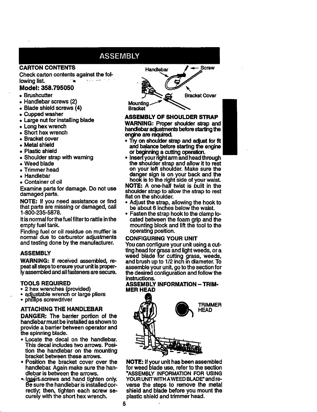
ATTACHING THE HANDLEBAR
DANGER: The barrier portion of the
handlebar must be installed as shown to
provide a barrier between operator and
the spinning blade.
• Locate the decal on the handlebar.
This decal includes two arrows. Posi-
tion the handlebar on the mounting
bracket between these arrows.
• Position the bracket cover over the
handlebar. Again make sure the han-
dlebar is between the arrows.
*, I_,_rt-screws and hand tighten only.
Be sure the handlebar is installed cor-
rectly; then, tighten each screw se-
curely with the short hex wrench.
ASSEMBLY OF SHOULDER STRAP
WARNING:
engineare required.
• Insert'
the
on your left Make sure the
danger sign is on your back and the
hook is to the right side of your waist.
NOTE: A one-half twist is built in the
shoulder strap to allow the strap to rest
flat on the shoulder.
• Adjust the strap, allowing the hook to
be about 6 inches below the waist.
• Fasten the strap hook to the clamp lo-
cated between the foam grip and the
mounting block and lift the tool to the
operating position.
CONFIGURING YOUR UNIT
You can configure your unit using a cut-
ting head for grass and light weeds, or a
weed blade for cutting grass, weeds,
and brush up to 1/2 inch in diameter. To
assemble your unit, go to the section for
the desired configuration and follow the
instructions.
ASSEMBLY INFORMATION - TRIM-
MER HEAD
) TRIMMER
HEAD
NOTE: Ifyourunithasbeen assembled
forweed blade use, referto the section
=ASSEMBLY INFORMATIONFOR USING
YOURUNITWITHAWEEDBLADE"and re-
verse the steps to remove the metal
shield and blade before you mountthe
plasticshieldand trimmerhead.
5
ATTACHINGTHEPLASTICSHIELD
ANDTRIMMERHEAD
WARNING:Theshieldmustbeproperly
installed.The shield providespartial
pmtsctionfromtheriskofthrown objects
to _ operator and others and is
equil_3edwitha linelirnltdrwhichct_sex-
casslinetotheproper length.The linelim-
- iter(on undersideof shield)issharpand
cancut you.
Remove wing nut from shield.
Insertbracket intoslot on shield.
• Pivot shield untilboltpasses through
hole in bracket.
Tightenthe wing nut securely.
Ifyourunithas a plasticcoveroverthe
threads on the threaded shaft,remove
the covetingto exposethe threads.
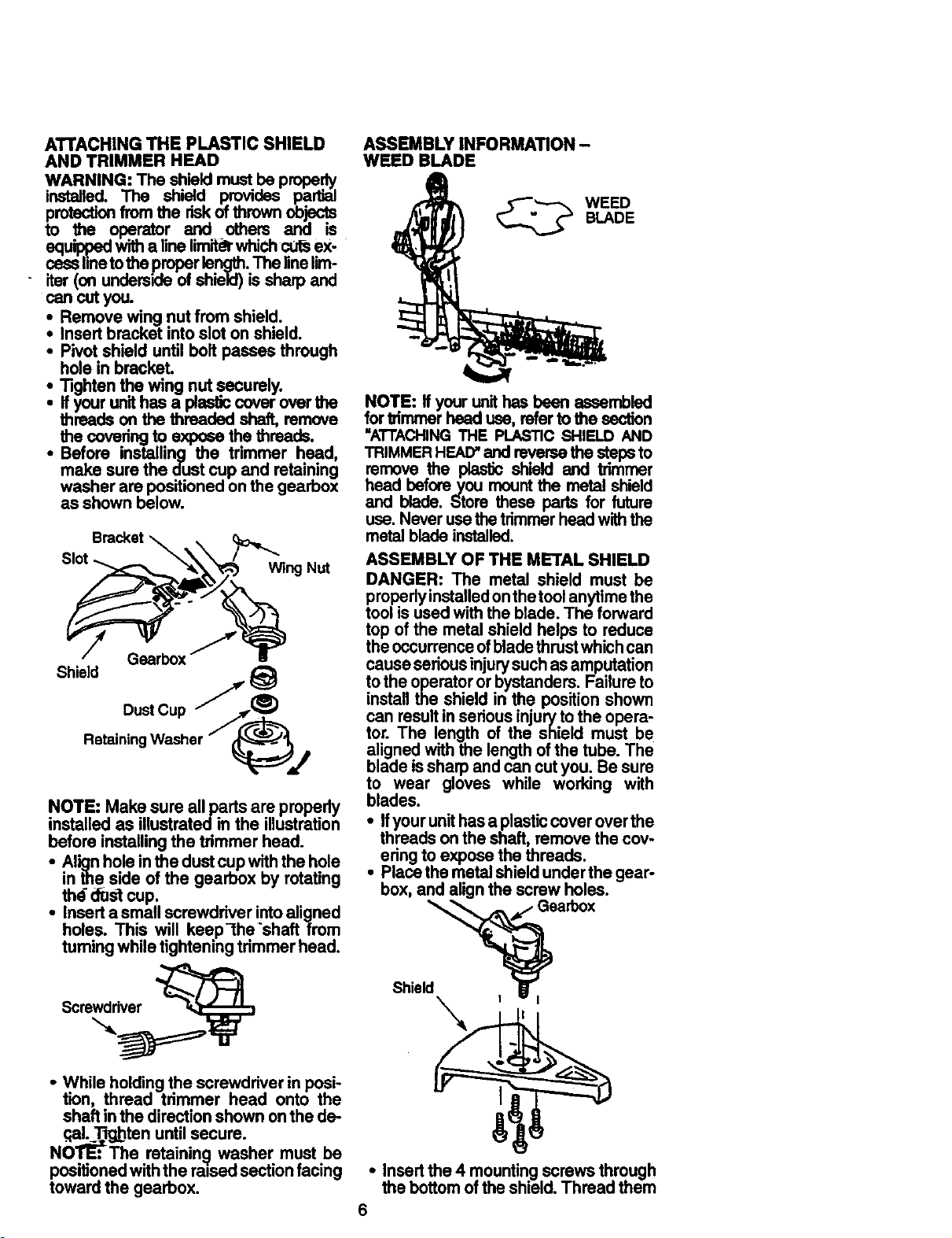
• Before installing the trimmer head,
make sure the dustcup and retaining
washer are positionedonthe gearbox
as shown below.
Bracket _ . c__
RotainiDnU_er / _
NOTE: Make sure all parts are propedy
installed as illustratedin the illustration
before installingthe trimmer head.
• Alignholein the dustcupwiththe hole
inthe side of the gearbox by rotating
thd _st cup.
• Inserta smallscrewdriver intoaligned
holes. Th_ will keep-the'shaft from
tumingwholetighteningtrimmerhead.
Screwdriver
• While holdingthe screwdriver in posi-
tion, thread trimmer head onto the
shaft inthe directionshown onthe de-
.qal_T_jbtenuntil secure.
NOTE:The ratainin(j washer must be
positionedwiththe ra0sedsectionfacing
toward the gearbox.
ASSEMBLY INFORMATION -
WEED BLADE
WEED
BLADE
NOTE: If your unit has been assembled
for _mmer head use, refer to the section
"ATTACHINGTHE PLASTIC SHIELD AND
TRIMMER HEAD"and reverse the steps to
remove the plastic shield and trimmer
head before you mount the metal shield
and blade. Store these pads for future
use. Never use the trimmer head with the
metal blade installed.
ASSEMBLY OF THE METAL SHIELD
DANGER: The metal shield must be
properiyinstalled on the tool anytime the
tool is used with the blade. The forward
top of the metal shield helps to reduce
the occurrence ofblade thrust which can
cause serious injury such as amputation
to the operator or bystanders. Failure to
install the shield in the position shown
can result in serious injury to the opera-
tor. The length of the shield must be
aligned with the length of the tube. The
blade is sharp and can cut you. Be sure
to wear gloves while working with
blades.
• Ifyour unit has a plastic cover over the
threads on the shaft, remove the cov-
ering to expose the threads.
• Place the metal shield under the gear-
box, and align the screw holes.
Shield_J, Gearb°x
• Insertthe 4 mountingscrews through
the bottomofthe shield.Thread them
6
into the gearbox. Tighten evenly and
securely with one ofthe hex wrenches
provided.
ASSEMBLY OF THE METAL BLADE
WARNING: Do not use any blades, or
fasteninghardwareoffie"thanthewash-
ers and nutsillustratedinthe followingil.
lustrations.These partsmustbe provided
by Sears, and installedas shown below.
Failuretouseproperpartscancausethe
bladeto fly offand seriouslyhurtyou or
others.
NOTE: The dust cup and retaining
washer are located onthe gearbox and
notin the parts bag.
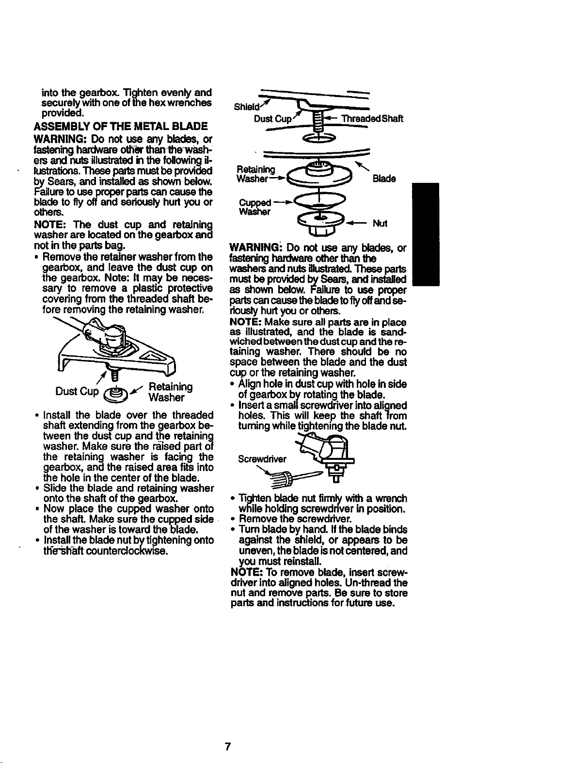
• Remove the retainerwasher from the
gearbox, and leave the dust cup on
the gearbox. Note: It may be neces-
sary to remove a plastic protective
covering from the threaded shaft be-
fore removingthe retaining washer.
Dust Cup (_='_ WasherRetaining
• Install the blade over the threaded
shaft extendingfrom the gearbox be-
tween the dust cup and the retaining
washer. Make sure the raised part of
the retaining washer is facing the
gearbox, and the raised area fits into
the hole in the center ofthe blade.
• Slide the blade and retainingwasher
ontothe shaft ofthe gearbox.
• Now place the cupped washer onto
the shaft. Make sure the cupped side
ofthe washer is toward the blade.
• Installthe bladenutb_/ti_ghteningonto
th'e'_haftcounterolockwJse.
Shield''_
DustCup/" _ ThreadedShaft
m
Retaining _ _'_
Washer--__ Blade
WARNINGi Do not use any blades, or
fasteninghardwareotherthanthe
washersand nutsillustrated.These parts
mustbe providedbySeam, and installed
as shown below. Failureto use proper
partscancause thebladetotiyoffandse-
riouslyhurtyou or others.
NOTE: Make sure all partsare inplace
as illustrated, and the blade is sand-
wichedbetween thedustcupandthe re-
taining washer. There should be no
space between the blade and the dust
cup or the retainingwasher.
i Alignholein dustcupwith holeinside
of gearboxby rotatingthe blade.
Inserta smallscrewdriverintoaligned
holes. This will keep the shaft from
tumingwhile tighteningthe blade nut.
Scre__
Tightenblade nutfirmlywitha wrench
i while holding position.
screwdnverin
Remove the screwdriver.
• Turn bladeby hand. Ifthe blade binds
against the shield, or appears to be
uneven,thebladeisnotcentered,and
you must reinstall.
NOTE: To remove blade, insertscrew-
ddver intoaligned holes. Un-threadthe
nut and remove parts. Be sureto store
partsand instructionsforfuture use.
7
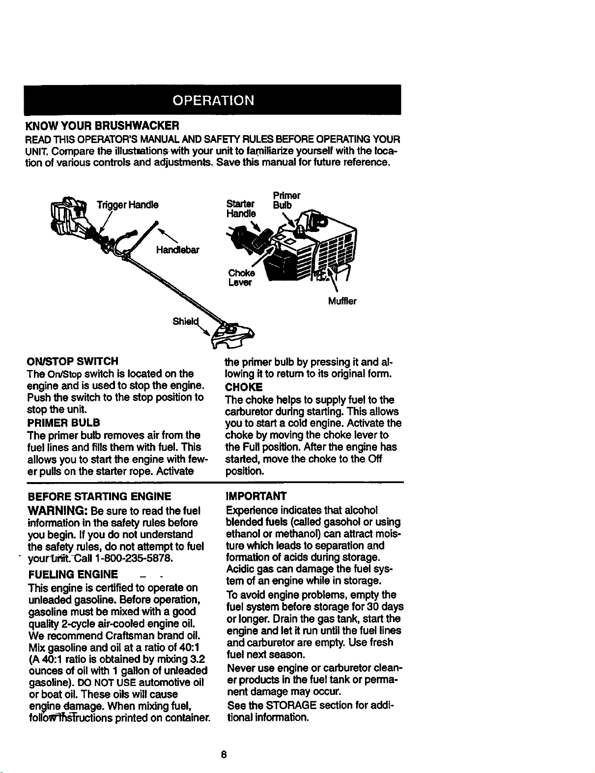
KNOW YOUR BRUSHWACKER
READ THIS OPERATOR'S MANUAL AND SAFETY RULES BEFORE OPERATING YOUR
UNIT. Compare the illustmtionswith your unit to familiarize yourself with the loca-
tion of various controls and adjustments. Save this manual for future reference.
Trigger Handle
Handlebar
Pdrner
Starter Bulb
Muffler
ON/STOP SWITCH
The On/Stop switch is located on the
engine and is used to stop the engine.
Push the switch to the stop position to
stop the unit•
PRIMER BULB
The primer bulb removes air from the
fuel lines and fills them with fuel. This
allows you to start the engine with few-
er pulls on the starter rope. Activate
the primer bulb by pressing it and al-
lowing it to retum to its original form.
CHOKE
The choke helps to supply fuel to the
carburetor during starting. This allows
you to start a cold engine. Activate the
choke by moving the choke lever to
the Full position. After the engine has
started, move the choke to the Off
position.
BEFORE STARTING ENGINE
WARNING: Be sure to read the fuel
informationin the safety rules before
you begin. Ifyou do not understand
the safety rules, do not attempt to fuel
• yourIJi'_t._,all 1-800-235-5878.
FUELING ENGINE -
This engine iscertifiedto operate on
unleaded gasoline. Before operation,
gasoline mustbe mixed with a good
quality2-cycle air-cooled engine oil.
We recommend Craftsman brand oil.
Mix gasoline and oil at a ratioof 40:1
(A 40:1 ratio is obtained by mixing3.2
ounces of oil withI gallon of unleaded
gasoline). DO NOTUSE automotiveoil
or boat oil. These oilswill cause
engine damage. When mixingfuel,
foliow']f_]'mctions printed on container.
IMPORTANT
Experienceindicates that alcohol
blendedfuels (called gasoholor using
ethanolor methanol)can attract mois-
turs which leadsto separation and
formationof acids duringstorage.
Acidicgas can damage thefuel sys-
tam of an engine while in storage.
To avoidengine problems,empty the
fuel systembefore storagefor30 days
or longer.Drain the gas tank, startthe
engine and let it rununtilthe fuel lines
and carburetor are empty. Use fresh
fuel nextseason.
Never use engine or carburetor clean-
er products in the fuel tank or perma-
nent damage may occur.
See the STORAGE section for addi-
tionalinformation.
STOPPING YOUR ENGINE
• Move the On/Stop switch to the
STOP position.
• If engine does not stop, move choke
to the Full Choke position.
STARTING YOUR Ei_GINI=" "-
WARNING: The trimmer head will turn
while starling the engine.
Avoid any contact with the muffler. A hoz
muffler can cause serious bums.
• Rest engine and shield on ground,
supporting tdmmer head off ground.
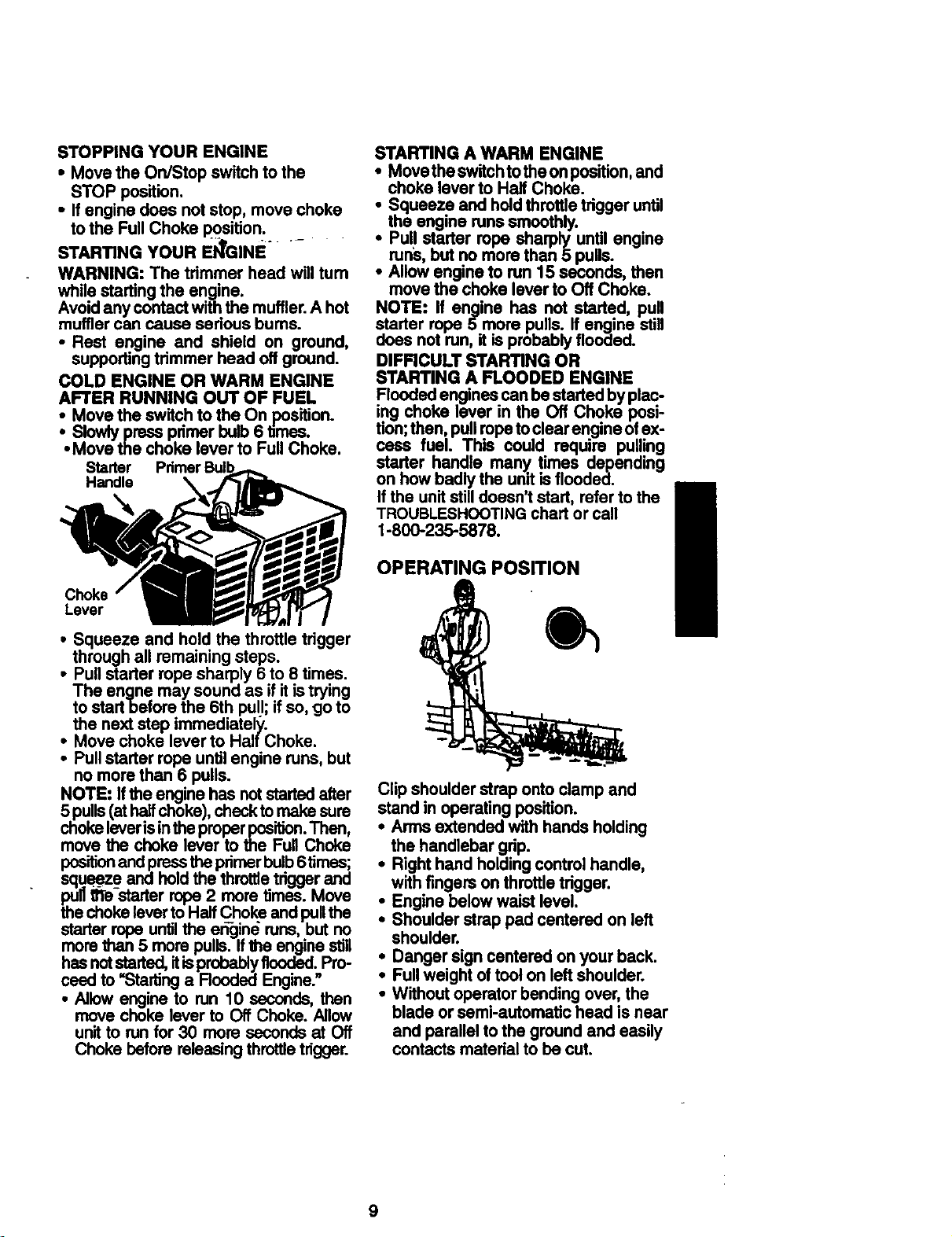
COLD ENGINE OR WARM ENGINE
AFTER RUNNING OUT OF FUEL
• Move the switch to the On position.
• Slowly press pdmer bulb 6 times..
• Move the choke lever to Full ChoKe.
Starter Pdmer BulbA
Handle _ ._-_1_
Lever T I
• Squeeze and hold the throttle tdgger
through all remaining steps.
i ull starter rope sharply 6 to 8 times.
The engne may sound as if it is trying
to startbefore the 6th pull; if so, go to
the next step immediately.
Move choke lever to Half Choke.
• Pull starter rope until engine runs, but
no more than 6 pulis.
NOTE: If the engine has not started after
5 pulls (at half choke), check to .make_sure
choke lever isin the proper position. Inen,
move the choke lever to the Full Choke
positionand press the primer bulb 6timas i
squeeze and hold the throme trigger ano
pull 8Te-starter rope 2 more times.. Move
the choke lever to Half ChoKe ano pullthe
starter rope until the e_gin_ runs, but
more than 5 more pulls. If the engine so,
has not started, itisprobably flooded;Pro-
need to "Starting a Flooded Engine.
• Allow engine to run 10 seconds, then
move choke lever to Off Choke. Allow
unit to run for 30 more seconds at Off
Choke before releasing throttle trigger.
STARTING A WARM ENGINE
• Movetheswitchtotheonposition, and
choke lever to Half Choke.
• Squeeze and hold throttle trigger until
the engine runs smoothly.
• Pull starter rope sharply until engine
runs, but no more than 5 pulls.
• Allow engine to run 15 seconds, then
move the choke lever to Off Choke.
NOTE: If engine has not started, pull
starter rope 5 more pulls. If engine still
does not run, it is probably flooaea.
DIFFICULT STARTING OR
STARTING A FLOODED ENGINE
Floodedenginescanbe started.by plac-
ing choke lever in the Off ChOKe.posi-
tion;then pullropetoclearengineoiex-
cass fuel. This could require pulling
starter handle many times delpending
on how badly the unitis floooea.
Ifthe unitstill doesn't start, referto the
TROUBLESHOOTINGchartor call
1-800-235-5878.
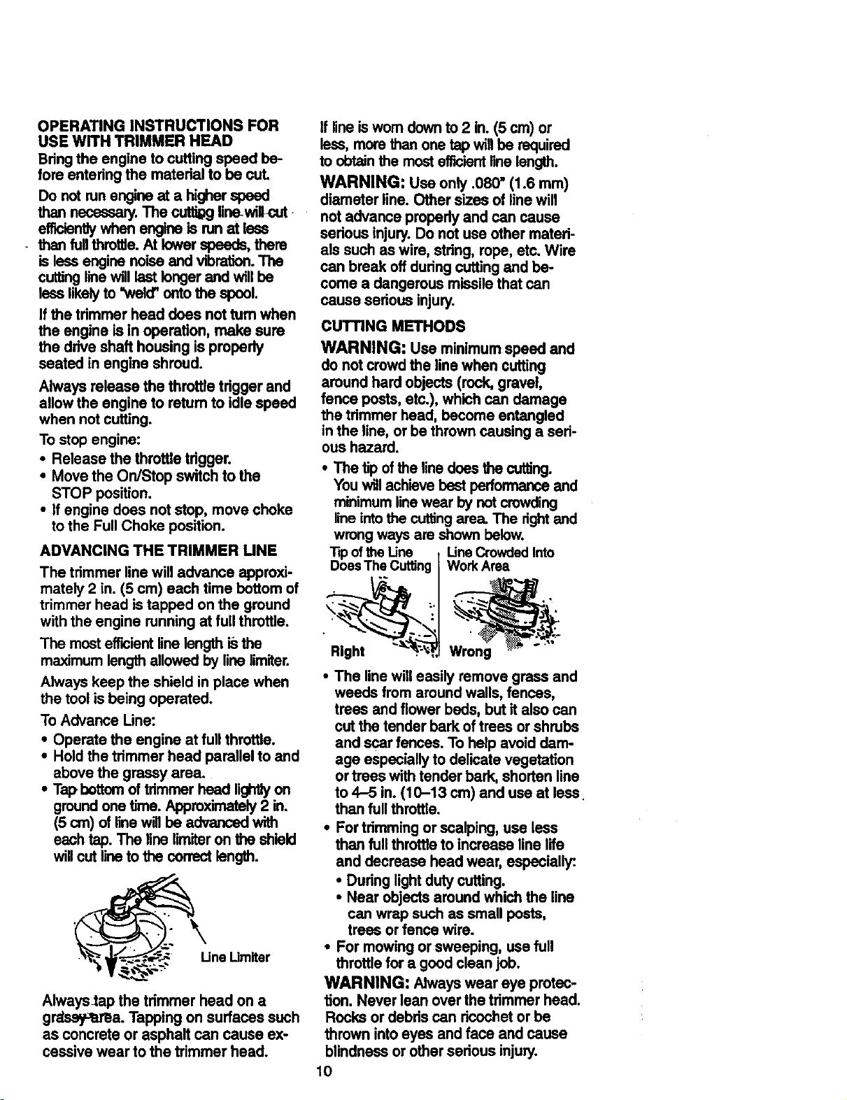
OPERATING POSITION
Clip shoulder strap onto clamp and
stand in operating position.
• Arms extended with hands holding
the handlebar gdp.
• Right hand holding control handle,
with fingers on throttle tdgger.
• Engine below waist level.
• Shoulder strap pad centered on left
shoulder.
• Danger sign centered on your back.
• Full weight of toot on left shoulder.
• Without operator bending over, the
blade or semi-automatic head is near
and parallel to the ground and easily
contacts material to be cut.
9
OPERATING INSTRUCTIONS FOR
USE WITH TRIMMER HEAD
Bring the engine to cutting speed be-
fore entering the material to be cut.
Do not run engine at a higher speed
than necessary. The cuttigg line-willo_
efficiently when engine is run at less
than fullthrotlJe.At lower speeds, there
is less engine noise and vibration. The
cutting line will last longer and will be
less likely to "weld' onto the spool.
If the trimmer head does not tum when
the engine is in operation, make sure
the drive shaft housing is properly
seated in engine shroud.
Always release the throttle trigger and
allow the engine to retum to idle speed
when not cutting.
To stop engine:
• Release the throttle tdgger.
• Move the On/Stop switch to the
STOP position.
• if engine does not stop, move choke
to the Full Choke position.
ADVANCING THE TRIMMER UNE
The trimmer line will advance approxi-
mately 2 in. (5 cm) each time bottom of
trimmer head is tapped on the ground
with the engine running at full throttle.
The most efticient line length is the
maximum length allowed by line lirniter.
Always keep the shield in place when
the tool is being operated.
To Advance Line:
• Operate the engine at full throttle.
• Hold the trimmer head parallel to and
above the grassy area.
• Tap,bottom of trimrner head lightlyon
ground one time. Approximately 2 in.
(5 cm) of line wig be advanced with
each tap. The line limiter on _ shield
will cut line to the correct length.
Always_ap the trimmer head on a
grdsey_ma. Tapping on surfaces such
as concrete or asphalt can cause ex-
cessivewear tothe trimmer head.
If lineisworn downto2 in.(5 cm) or
less,morethan one tap willbe required
to obtainthe mostefficientlinelength.
WARNING: Use only .080" (1.6 mm)
diameter line. Other sizes of linewill
notadvance propedyand can cause
serious injury.Do notuse other materi-
als such aswire, stdng, rope, etc. Wire
can break off duringcuttingand be-
come a dangerous missilethat can
cause serious injury.
CUTrlNG METHODS
WARNING: Use minimum speed and
do not crowd the line when cutting
around hard objects (rock, gravel,
fence pests, etc.), which can damage
the trimmer head, become entangled
in the line, or be thrown causing a seri-
ous hazard.
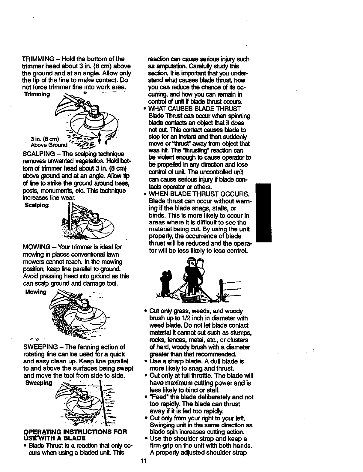
• The tip of the line does the cutting.
You will achieve best performance and
minimum line wear by not crowding
line into the cuffing area. The right and
wrong ways are shown below.
Tipof the Line Une Crowded Into
DoesThe Cutting WorkArea
Right :_._'_"_
• The line willeasily remove grass and
weeds from aroundwalls, fences,
trees and flower beds, but italso can
cutthe tender barkof trees or shrubs
and scar fences. To help avoiddarn-
age especiallyto delicate vegetation
or trees withtender bark, shorten line
to 4-5 in. (10-13 cm) and use at less
thanfullthrottle.
• For trimmingor scalping,use less
than fullthrottleto increase line life
and decrease head wear, especially:.
• During lightdutycutting.
• Near objectsaround whichthe line
can wrap such as small posts,
tress or fence wire.
• For mowingorsweeping, use full
throttle for a good clean job.
WARNING: Alwayswear eye protec-
tion. Never lean over the trimmerhead.
Racks or debdscan ricochetorbe
thrown intoeyes and face and cause
blindnessor other serious injury.
10
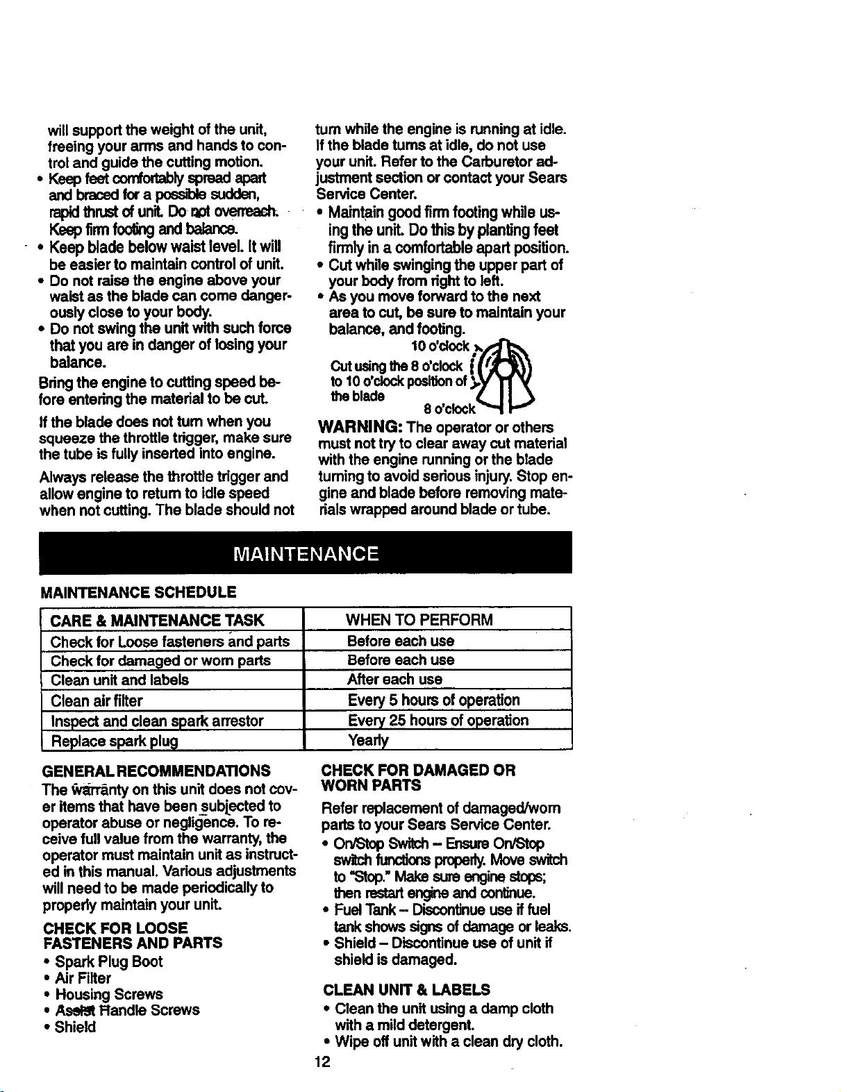
TRIMMING- Holdthebottomofthe
trimmerheadabout3in.(8cm)above
thegroundandatanangle.Allowonly
thetipofthelinetomakecontact.Do
notforcetrimmerlineintoworkarea.
Trimming :.....
3 in.(8 cro) _ _"_.___._'-1 _-'"
AboveGround ',___*_
SCALPING -The scalping technique
removesuowantedvegetal_. Holdbot-
tomof Vimmer head about 3 in. (8 cm)
abevegroundandatan angla.Allow_
of line to sirra the ground around troes,
posts, monuments, etc. This technique
increases line wear.
Scalping
MOWING - Yourtrimmeris idealfor
mowingin placesconventionallawn
mowerscannotroach.Inthe mowing
position,keep lineparallelto ground.
Avoidpressingheadintogroundasthis
canscalpgroundand damagetool.
Mowing
SWEEPING - The fanning action of
rotating line can be used fbr a quick
and easy clean up. Keep line parallel
to and above the surfaces being swept
and move the tool from side to side.
Sweeping __
b0PERATING INSTRUCTIONS FOR
S_"WITH A BLADE
• Blade "rhrust is a reaction that only oc-
curs when using a bladed unit This
reactioncancaussssriousinjurysuch
asamputation.CarofuUystudythis
_. It is importantthat you under-
stand what causas blade thrust, how
you can reduce the chance of itsoc-
cur_g, and how you can remain in
controlof unitif blade thrust occurs.
• WHAT CAUSES BLADE THRUST
Blade Thrust can occur when spinning
bladscor_actsanobjectthatitdoas
not cut. This contact causes blade to
stop for _ instantand then suddenly
move or "lhrus_ away from object that
w=,s hit The "thrusting"reaction can
be violent enough to causs oparator to
beprope_ bl anydrec0onand_ose
conbol of uniL The uncontrolledunit
cancauseserisusinjunjifbladecon-
tactsoperator or others.
• WHEN BLADE THRUST OCCURS.
Blade thrust can occur without wam-
ing if the blade snags, stalls, or
binds. This is more likely to occur in
areas where it is difficult to see the
material being cut. By using the unit
properly, the occurrence of blade
thrust will be reduced and the opera-
tor will be less likely to lose control.
• Cut only grass, weeds, and wcody
brush up to 1/2 inch in diameter with
weed blade. Do not let blade contact
material itcannot cut such as stumps,
rocks, fences, metal, etc., or clusters
of hard, woody brush with a diameter
greater than that recommended.
• Use a sharp blade. A dull blade is
more likely to snag and thrust.
• Cut only at full throttle. The blade will
have maximum cutting power and is
leas likely to bind or stall.
• "Feed" the blade deliberately and not
too rapidly. The blade can thrust
away if it is fed too rapidly.
• Cut only from your dght to your lefL
Swinging unitin the same direction as
blade spin increases cutting action.
• Use the shoulder strap and keep a
firm grip on the unit with both hands.
A properly adjusted shoulder strap
11
willsupporttheweightoftheunit,
freeingyourarmsandhandstocon-
trolandguidethecuttingmotion.
• Ksepfsetcon_o_aUyspreadapart
andbracedfora possrolesudden,
rapidthrustofunit.Dor_oto_.
Keep foo andba .x=
• Keepbladebelowwaistlevel.Itwill
be easier to maintain control of unit.
• Do not raise the engine above your
waist as the blade can come danger-
ously close to your body.
• Do not swing the unit with such force
that you are in danger of losing your
balance.
Bring the engine to cuffing speed be-
fore entering the material to be cut.
If the blade does not tum when you
squeeze the throttle trigger, make sure
the tube is fully inserted into engine.
Always release the throttle trigger and
allow engine to return to idle speed
when not cutting. The blade should not
MAINTENANCE SCHEDULE
tum while the engine is running at idle.
if the blade turns at idle, do not use
your unit. Refer to the Carburetor ad-
justment section or contact your Sears
Service Center.
• Maintain good firm footing while us-
ing the unit. Do this by planting feet
firmly in a comfortable apart position.
• Cut while swinging the upper part of
your body from right to left.
• As you move forward to the next
area to cut, be sure to maintain your
balance, and footing.
lOo'c ,k
eo'clo I
to 10 O'ClOCkpositionof _,.y' 1'I
the blade • II •
8 O'Clock""t
WARNING: The operator or others
must not try to clear away cut material
with the engine running or the blade
fuming to avoid serious injury. Stop en-
gine and blade before removing mate-
dais wrapped around blade or tube.
CARE & MAINTENANCE TASK
Check for Loose fasteners and parts
Check for damaged or worn parts
Clean unit and labels
Clean air filter
Inspect and clean spark arrestor
Replace spark plug
WHEN TO PERFORM
Before each use
Before each use
After each use
Every 5 hours of operation
Every 25 hours of operation
Yearly
GENERAL RECOMMENDATIONS
The _r'_r_nty on this unit does not cov-
er items that have beensubjected to
operator abuse or negligence. To re-
ceive full value from the warranty, the
operator must maintain unit as instruct-
ed in this manual. Various adjustments
will need to be made periodically to
properly maintain your unit.
CHECK FOR LOOSE
FASTENERS AND PARTS
• Spark Plug Boot
• Air Filter
• Housing Screws
• Asel_ Flandle Screws
• Shield
CHECK FOR DAMAGED OR
WORN PARTS
Refer replacement of damaged/worn
partsto your Sears Service Center.
• On/Stop Switch- EnsureOn/Stop
switchfunctionsproperty.MoveswiPJn
to"Stop."Make sureenginestops;
thenrsstart angineand continue.
• FuelTank- Discontinueuseiffuel
tankshowssignsof damageor leaks,
• Shield - Discontinueuse of unitif
shield is damaged.
CLEAN UNIT & LABELS
• Clean the unit using a damp cloth
with a mild detergent.
• Wipe off unit with a clean dry cloth.
12
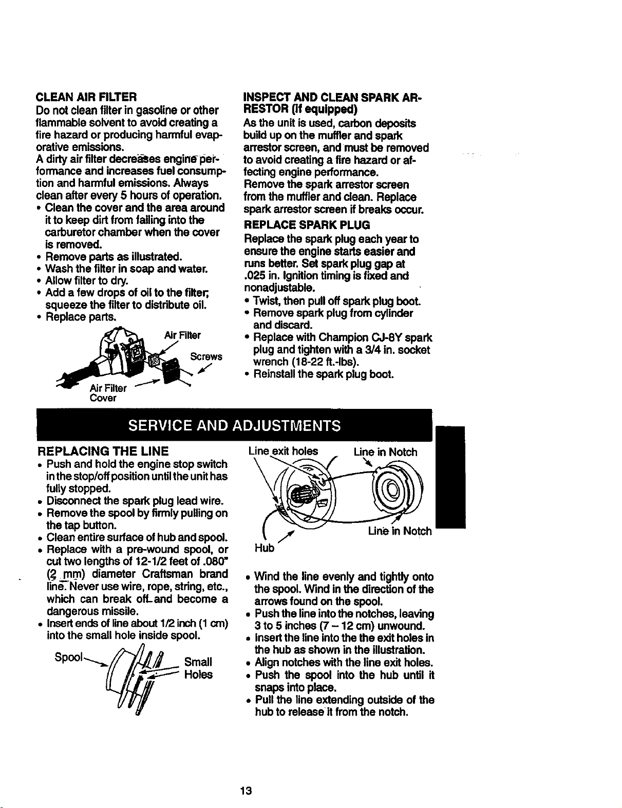
CLEAN AIR FILTER
Do notclean filterin gasoline or other
flammable solventto avoidcreating a
fire hazard or producing harmful evap-
orative emissions.
A dirtyairfilter decre_es engine-pei'-
formance and increases fuel consump-
tion and harmful emissions.Always
clean after every 5 hours of operation.
• Clean the cover and the area around
itto keep dirtfrom fallingintothe
carburetor chamber when the cover
is removed.
• Remove pads as illustrated.
• Wash the filter in soap and water.
• Allow filter to dry.
• Add a few drops of oilto the filter;,
squeeze the filterto distributeoil.
• Replace parts.
Cover
INSPECT AND CLEAN SPARK AR-
RESTOR (if equipped)
As the unitisused, carbondeposits
build upon the mufflerand spark
arrestor screen, and mustbe removed
to avoidcreating a fire hazard or af-
fecting engine performance.
Remove the spark arrestorscreen
from the mufflerand clean. Replace
spark arrestorscreen ifbreaks occur.
REPLACE SPARK PLUG
Replace the sparkplug each year to
ensure the engine startseasier and
runs better.Set spark pluggap at
.025 in. Ignitiontimingisfixed and
nonadjustable.
• Twist,then pull offspark plugboot.
• Remove spark plugfromcylinder
and discard.
• Replace with Champion CJ-8Y spark
plugand tightenwith a 3/4 in. socket
wrench (18-22 ft.-Ibs).
• Reinstallthe spark plugboot.
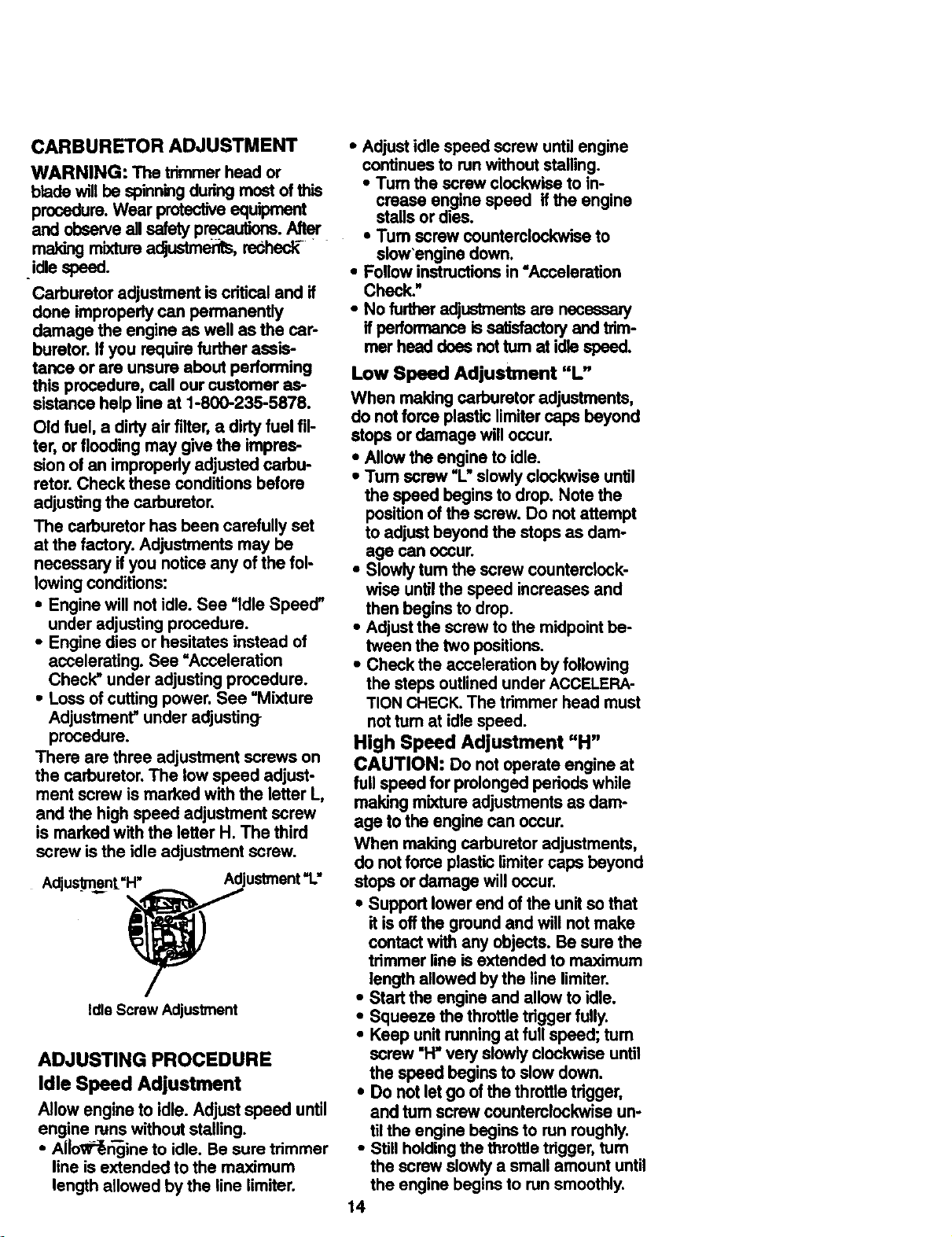
REPLACING THE LINE
• Push and hold the engine stop switch
inthe stop/off position until the unit has
fully stopped.
• Disconnect the spark plug lead wire.
• Remove the spool by firmly pulling on
the tap button.
• Clean entire surface of hub and spool.
• Replace with a pre-wound spool, or
cut two lengths of 12-1/2 feet of .080"
(2J_mrn) diameter Craftsman brand
line. Never use wire, rope, string, etc.,
which can break off-and become a
dangerous missile.
• Insert ends of line about 1/2 inch (1 cm)
into the small hole inside spool.
Lineexit holes Line in Notch
Hub
Une in Notch
• Wind the line evenly and tightly onto
the spool. Wind in the direction of the
arrows found on the spool.
• Push the line into the notches, leaving
3 to 5 inches (7 - 12 cm) unwound.
• insert the line intothe the exit holes in
the hub as shown in the illustration.
• Align notches with the line exit holes.
• Push the spool into the hub until it
snaps into place.
• Pull the line extending outside of the
hub to relesseit from the notch.
13
CARBURETOR ADJUSTMENT
WARNING: The trimmer head or
blade will be spinning dudng most of this
procedure. Wear protective equipment
and observe all safety precautions. After
making mixture adjustment, resheck-
.idle speed.
Carburetor adjustment is cdfical and if
done improperly can permanently
damage the engine as well as the car-
buretor. If you require further assis-
tance or are unsure about performing
this procedure, call our customer as-
sistance help line at 1-800-235-5878.
Old fuel, a dirty air filter, a dirty fuel fil-
ter, or flooding may give the impres-
sion of an improperly adjusted carbu-
retor. Check these conditions before
adjusting the carburetor.
The carburetor has been carefully set
at the factory. Adjustments may be
necessary if you notice any of the fol-
lowing conditions:
• Engine will not idle. See =Idle Speed"
under adjusting procedure.
• Engine dies or hesitates instead of
accelerating. See "Acceleration
Check" under adjusting procedure.
• Loss of cutting power. See "Mixture
Adjustment" under adjusting
procedure.
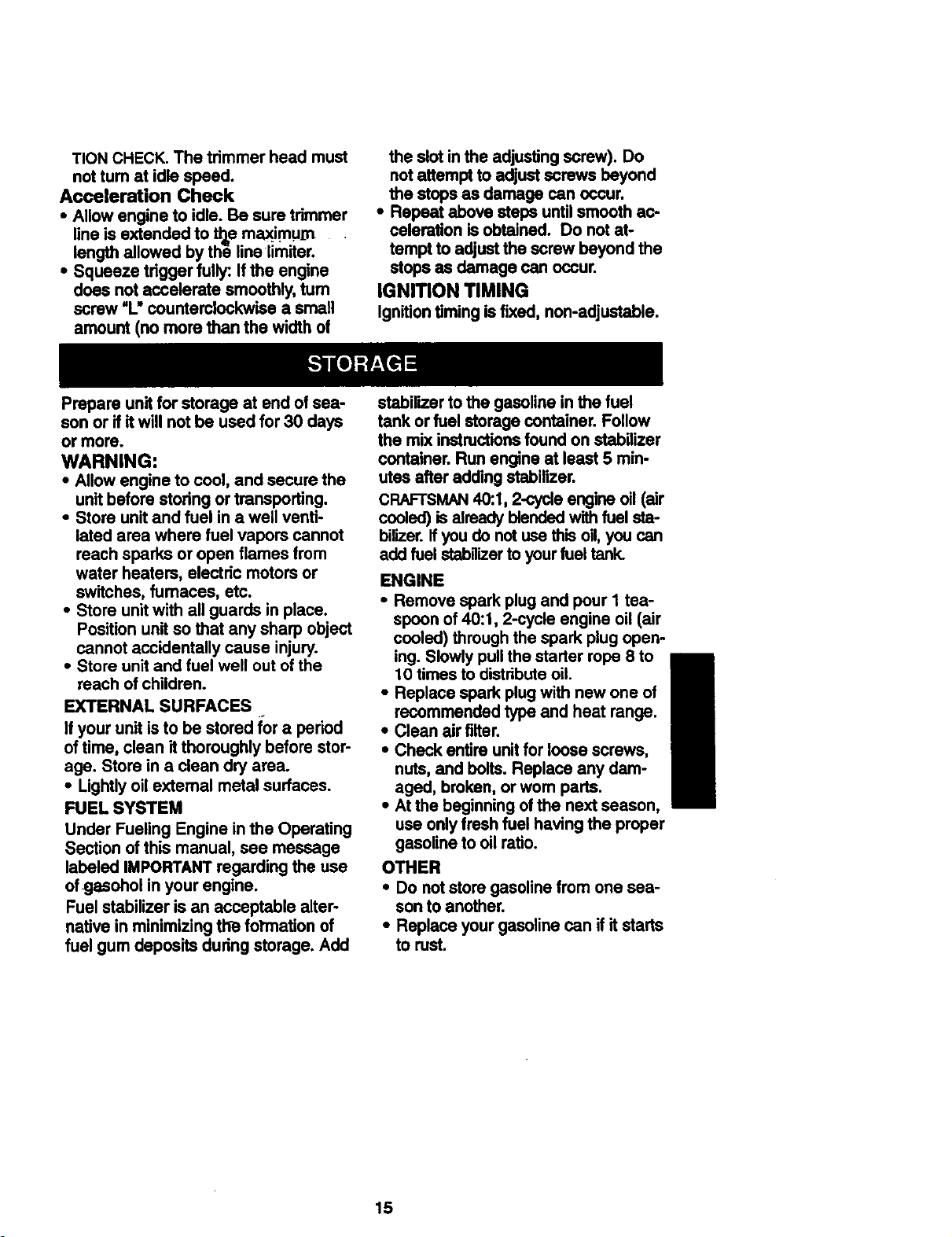
There are three adjustment screws on
the carburetor. The low speed adjust-
ment screw is marked with the letter L,
and the high speed adjustment screw
is marked with the letter H. The third
screw is the idle adjustment screw.
Adjuslm_ent=H" Adjustment'1."
IdleScrew Adjustment
ADJUSTING PROCEDURE
Idle Speed Adjustment
Allow engineto idle. Adjustspeed until
engine runswithoutstalling.
• Al_o_P_ine to idle. Be sure trimmer
line is extended to the maximum
length allowed by the line limiter.
• Adjust idle speed screw until engine
continues to run w'Rhout stalling.
• Turn the screw clockwise to in-
crease engine speed if the engine
stalls or dies.
•Tum screw counterclockwise to
slow'engine down.
• Follow instructions in "Acceleration
Check."
• No further adjustments am necessary
if performance is sstisfactory and trim-
mer head does not turn at idle speed.
Low Speed Adjustment "L"
When makingcarburetor adjustments,
do notforce plasticlimitercaps beyond
stops or damage willoccur.
• Allowthe engine to idle.
• Turn screw "L"slowlyclockwise until
the speed begins to drop, Note the
positionof the screw. Do notattempt
to adjustbeyondthe stops as dam-
age can occur.
• Slowly tum the screw countemlock-
wise untilthe speed increases and
then beginsto drop.
• Adjustthe screw to the midpointbe-
tween the two positions.
• Check the accelerationby following
the steps outlinedunder ACCELERA-
TION CHECK.The tdmmer head must
nottum at idlespeed.
High Speed Adjustment "H"
CAUTION: Do not operate engine at
full speed for prolongedpedods while
making mixtureadjustmentsas dam-
age to the enginecan occur.
When making carburetor adjustments,
do notforce plasticlimitercaps beyond
stops or damage will occur.
• Supportlowerend of the unitso that
it isoffthe groundand will notmake
contactwith any objects. Be surethe
trimmerline is extended to maximum
length allowedby the line limiter.
• Start the engine and allow to idle.
• Squeeze the throttletdgger fully.
• Keep unitrunningat full speed; turn
screw "H"very slowlyclockwiseuntil
the speed beginsto slowdown.
• Do notlet go ofthe throttletdgger,
and tum screwcounterclockwiseun-
tilthe engine beginsto run roughly.
• Stillholdingthe throttle trigger,turn
the screwslowlya small amountuntil
the engine beginsto runsmoothly.
14
TION CHECK. The trimmer head must
not tum at idle speed.
Acceleration Check
• Allow engine to idle. Be sure trimmer
line is extended to the maxim.urn
length allowed by th6 line limiter.
• Squeeze trigger fully:. If the engine
does not accelerate smoothly, turn
screw =L"countemlockwise a small
amount (no more than the width of
the slot in the adjustingscrew). Do
notattempt to adjustscrews beyond
the stops as damage can occur.
• Repeat above steps untilsmoothac-
celeration isobtained. Do not at-
tempt to adjustthe screw beyondthe
stopsas damage can occur.
IGNITION TIMING
Ignitiontiming is fixed, non-adjustable.
Prepare unit for storage at end of sea-
son or if it will not be used for 30 days
or more.
WARNING:
• Allow engine to cool, and secure the
unit before storing or transporting.
• Store unit and fuel in a well venti-
lated area where fuel vapors cannot
reach sparks or open flames from
water heaters, electric motors or
switches, fumaces, etc.
• Store unit with all guards in place.
Position unit so that any sharp object
cannot accidentally cause injury.
• Store unit and fuel well out of the
reach of children.
EXTERNALSURFACES
If your unit is to be stored for a period
of time, clean it thoroughly before stor-
age. Store in a clean dry area.
• Lightly oil external metal surfaces.
FUEL SYSTEM
Under Fueling Engine in the Operating
Section of this manual, see message
labeled IMPORTANT regarding the use
ofgasohol in your engine.
Fuel stabilizer is an acceptable alter-
native in minimizing the formation of
fuel gum deposits during storage. Add
stabilizer to the gasoline in the fuel
tank or fuel storage container. Follow
the mix instructions found on stabilizer
container. Run engine at least 5 min-
utes after adding stabilizer.
CRAFTSMAN 40:.1, 2-cycle engine oil (air
cooled) is already blended with fuel sta-
bir,:,er,if you do not use this oil, you can
add fuel stabnizer to your fuel tank.
ENGINE
• Remove spark plug and pour I tea-
spoon of 40:1, 2-cycle engine oil (air
cooled) through the spark plug open-
ing. Slowly pull the starter rope 8 to
10 times to distribute oil.
• Replace spark plug with new one of
recommended type and heat range.
• Clean air filter.
• Check entire unit for loose screws,
nuts, and belts. Replace any dam-
aged, broken, or wom parts.
• At the beginning of the next season,
use only fresh fuel having the proper
gasoline to oil ratio.
OTHER
• Do not store gasoline from one sea-
son to another.
• Replace your gasoline can if it starts
to rust.
15
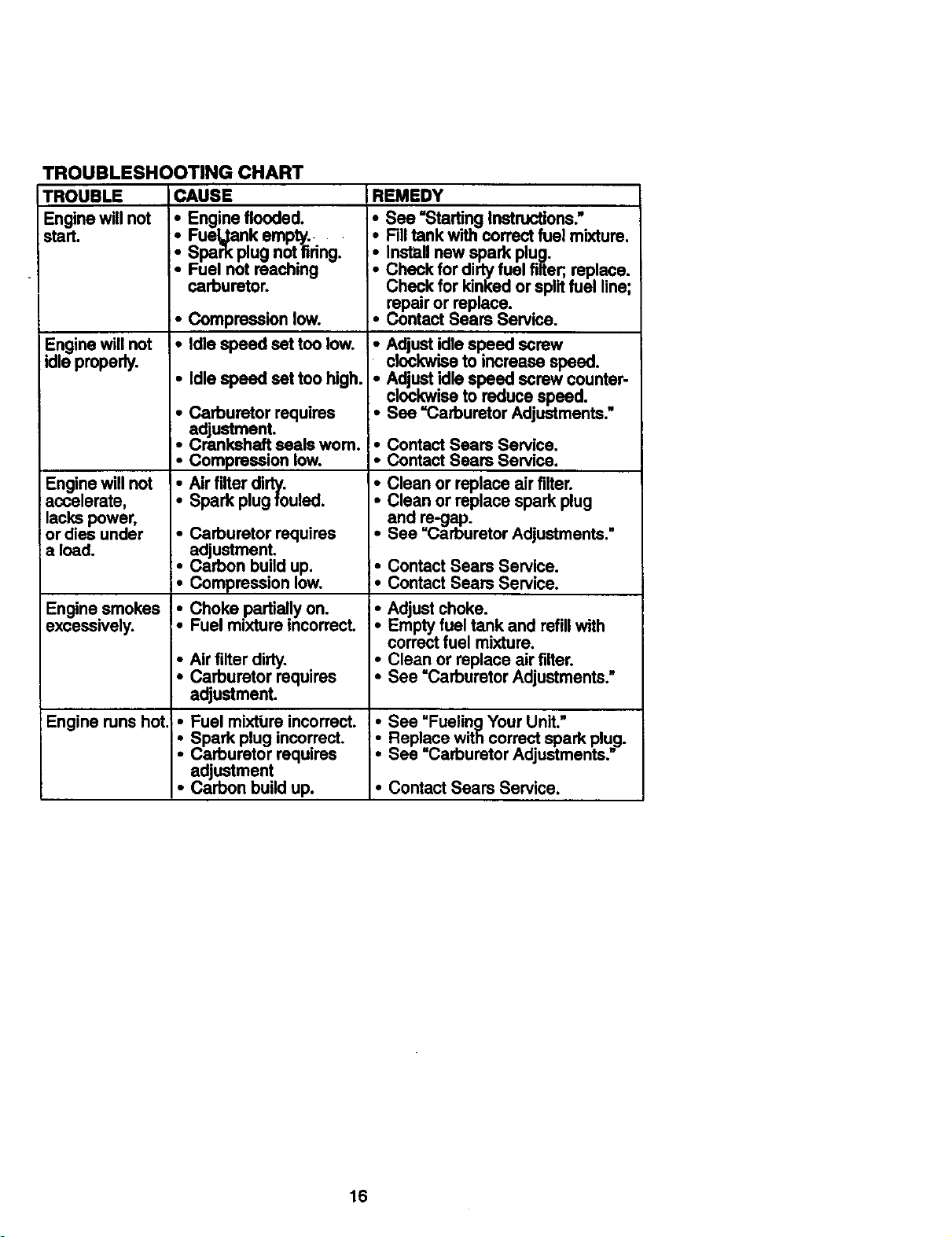
TROUBLESHOOTING CHART
TROUBLE
Engine will not
start.
Engine will not
idle properly.
Engine will not
accelerate,
lacks power,
or dies under
a load.
Enginesmokes
excessively.
Engine runs hot.
CAUSE
_Engine flooded.
Fueljank empty.
Spark plug not firing.
Fuel not reaching
carburetor.
• Compression low.
• Idle speed set too low.
• Idle speed set too high.
• Carburetor requires
adjustment.
• Crankshaftseals wom.
• Compression low.
• Air filterdirty.
• Spark plug fouled.
• Carburetor requires
adjustment.
• Carbon build up.
• Compression low.
• Choke partially on.
• Fuel mixture incorrect.
• Air filter dirty.
• Carburetor requires
adjustment.
• Fuel mixtbre incorrect.
• Spark plug incorrect.
Carburetor requires
adjustment
• Carbon build up.
REMEDY
See "StartingInstructions."
Filltank withcorrect fuel mixture.
• Install new spark plug.
Check for dirty fuel filter;, replace.
Check for kinked or split fuel line;
repair or replace.
• Contact Sears Service.
i Adjust idlespeed screw
clockwiseto increase speed.
Adjustidlespeed screw counter-
clockwiseto reduce speed.
• See "Carburetor Adjustments."
• Contact Sears Service.
• Contact Seam Service.
• Clean or replace airfilter.
• Clean or replace spark plug
and re-gap.
• See =Carburetor Adjustments."
• Contact Sears Service.
• Contact Sears Service.
Adjust choke.
Empty fuel tank and refill with
correct fuel mixture.
• Clean or replace air filter.
See =Carburetor Adjustments."
• See "FueiingYour Unit,"
Replace with correct spark plug.
• See =Carburetor Adjustments."
• Contact Sears Service.
16

YOUR WARRANTY RIGI;;ITSAND OSUGA-
TIONS: The U. S. Enviro_rnsntaiProtection
Agency/CaliforniaAir Resources Board and
SEARS, ROEBUCK AND CO., arepleasedto
explaintheemissionscontrolsystemwarran-
tyonyourlawnandgardanequipmantangine.
Allnew_lity andlawnand gardenequipment
engines must be designed, built, and
equipped to meet the stringent anti-smog
standards. SEARS, ROEBUCK AND CO.
mustwarrantthe emission controlsystemon
yourlawn and garden equipmentengine for
thepedodsoftime listedbelow providedthere
has been no abuse, neglect, or improper
maintenance ofyourlawnand gardenequip-
mant engine.Youremissioncontrolsystemin-
dudes parts such as the carburetor and the
ignitionsystem. Where a warrantablecondi-
tionexits,SEARS, ROEBUCK AND CO. will
repair your lawn and garden equipment en-
gineat nocosttoyou.Expenses coveredun-
der warrantyincludediagnosis,partsand la-
bor. MANUFACTURER'S WARRANTY
COVERAGE: Ifany emissionsrelatedparton
yourengine (as listedunder EmissionsCon-
trolWarranty Parts List)isdefective or a de-
fectinthe matsdaisorworkmanshipofthe en-
ginecauses the failure of such an emission
related part, the part will be repaired or re-
placed b_ SEARS, ROEBUCK AND CO.
OWNER S WARRANTY RESPONSlBIM-
TIES: Asthe lawnand gardenequipmentan-
ginsowner,youare responsiblafortheperfor-
mance ofthe required maintenance listedin
yAourOwner's Manual. SEARS, ROEBUCK
ND CO. recommends thatyou retainall re-
csipts covering maintenance on your lawn
and garden equipment engine, but SEARS,
ROEBUCK AND CO. cannot deny warranty
solalyforthelackof receiptsorforyour failure
to ensure the performance of all scheduled
WARRANTY COMMENCEMENT DATE:
The warrantyperiod beginson the date the
lawn and garden equipment engine is pur-
chased. LENGTH OF COVERAGE: This
warrantyshailbefora pedodoftwoyearsfrom
the init_ data of purchase. WHAT IS COV-
ERED: REPAIR OR REPLACEMENT OF
PARTS. Repair or replacement of any war-
rantedpartwillbe performedat no chargeto
the owner at an approved SEARS Service
Center. Ifyou have any questionsrejgarding
yourwarrantydghtsand responsibilities,you
shouldcontactyour nearest authorizedser-
vice center or callSEARS, ROEBUCK AND
CO. at 1-800-235-5878 WARRANTY PE-
RIOD: Anywarrantedpartwhichisnotsched-
uisd for replacement as required mainte*
nanca, or whichIsscheduledonlyforregular
Inspactionto_ effectof=repairorreplaceas
necessary"shall be warranted for 2 years.
Anywarrantedpartwhichisscheduled for re-
plasemantas requiredmaintenanceshallbe
warrantedfor the pedodoftime up tothe first
scheduled mplasement point for that part.
DIAGNOSIS: Theownershallnotbecharged
for diagnostic laborwhichleads to the deter-
ruination thata warranted part isdefective if
the diagnosticwork is performed at an ap-
proved SEARS Service Center. CONSE-
QUENTIAL DAMAGES: SEARS, ROE-
BUCK AND CO. maybeliablefordamagesto
otherenginecomponentscaused bythe fail-
ure of a warrantedpart stiltunder warranty.
WHAT IS NOT COVERED: All failures
caused byabuse,neglect,or impropermain-
tenance are notcovered. ADD-ON OR MO-
DIRE DPARTS. Thaussofedd-on or modified_
padscanbegroundsfordissJlowinga warranty_
daim. SEARS, ROEBUCKAND CO. is not li-_
able to cover failures of warranted parts_
caused by the use of add-on or modified
parts. HOW TO FiLE A CLAIM: If you have_
anyquestionsregardingyourwarrantyrights
and responsibilities,you shouldcontact your
nearest authorized service center or callm
SEARS, ROEBUCK AND CO. at
1-800-235-5878. WHERE TO GET WAR-
maintenance. Asthelawnandgardenequip- RANTY SERVICE: Warranty services or re-
mantangins owner,youshouldbe awarethat pairsshallbe providedat all SEARS Se_..
SE/_RS, ROEBUCKANDCO.maydenyyOU Centers. Call: 1-800-235-5878 MAIN'rE
wafraflty-covemge if your lawn and garden NANCE, REPLACEMENT AND REPAIR OF
equipmantangine ora pert of ithesfaileddue EMISSION RELATED PARTS: Any SEARS,
toabuse, neglect,impmpeTmathtenance,un- ROEBUCK AND CO. approvedreplacement
approved modifications,ortheuseofpartsnot partusedinthe performanceofany warranty
made or approvedbythe originalequipment maintenance or repair on emission related
manufacturer. You are responsiblefor pres- parts willbe providedwithout charge to the
entingyour lawn and garden equipment an- owner if the part is under warranty. EM!,TS_.
ginstoa SEARS Service Centerassoonasa SION CONTROLWARRANTY PARTSLIST:
problem exists. Warranty repairs shouldbe Carburetor,IgnitionSystem:Spark Plug(cov-
completedinareasonablearnountoftime,not ered up to maintenance schedule), Ignition
toexceed30 days. Ifyou haveanyquestions Module. MAINTENANCE STATEMENT: The
re._rding yourwarrantydghtsand respoasi- ownsrisresponsiblefortheperformance ofall
bihtias,you shouldcontact your nearest au- requiredmaintenanceas definedin the own-
thodzedservicecenter or callSEARS, ROE- er's manual.
BUCK AND CO. at 1-800-235-5878.
17
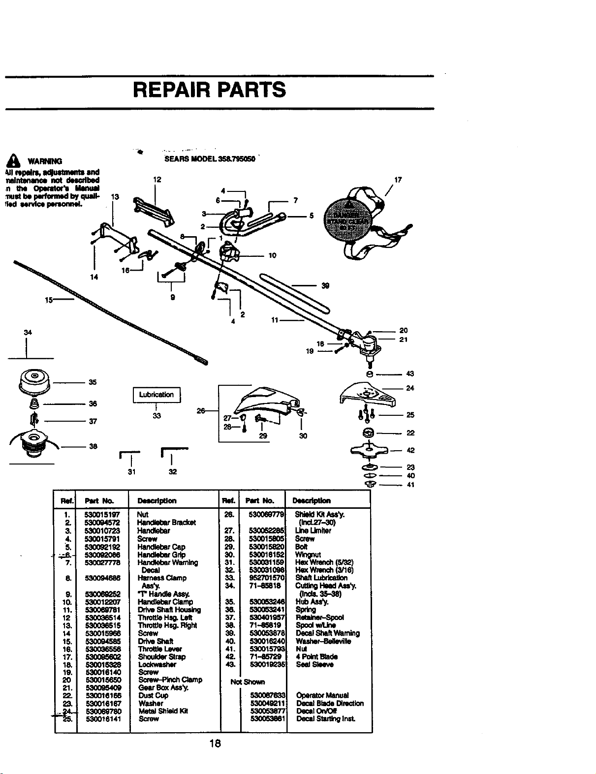
REPAIR PARTS
WARNING
SEARS MODEL358._ '
--38
2
4
n35
31"71 32 €_)-- 23
<:1;;>--40
Ref. Part No.
1. 530015197
2. 53OO94572
3. 5,30010723
4. 530015791
S. S300S21g2
--.,_.- 5300e20e6
7. 530027778
8.
9.
10.
11.
12
13.
14
15,
16.
17.
l&
lg.
20
21.
5300946_
53ooe_P.s2
530o122o7
530069781
530036514
53oo86515
53oo15_6
53oo94585
53oo_sss6
53oo_2
53oo15328
530016140
530015650
53oo_54o9
530016166
5,30016167
53oo6878o
530016141
Nut
Bmd_
Hendg_r
Screw
HandlebarCap
HandlebarG_
HandWaerWarning
Decal
HmnessClamp
"I" HandleAssy.
Hand_r Clamp
Drh_e,ShaRHou_g
ThrotUeHs_ Left
ThroWeHsg. Right
Screw
Drive Sl,aft
ThrottleLevw
Shoul_"Strap
Lockwuher
Screw
Screw-Pinch Clamp
Gear Box Ass'y.
o.._cup
Washer
Metal ShieldKit
Suew
26.
27,
28.
29.
30.
31.
32.
33.
34.
Pair No.
5300_9"/79
S300_.eS
530015e06
530015_0
530016152
53000115_
5300_109e
95270157G
71-85818
35. 53005_4_
36. 530053241
37. 53040195"/
38. 71--85819
39. 53005387e
40. 53001624€
41. 530015"/_
42. 71-85729
43. 53001S1_3_
NotS_:_n
53ooe7_3_
53oo4_11
53oor_
53oo53_1
Sh_dm/_y.
Oncl.2'r.-.,_o)
Une Umiter
Screw
Bolt
H_ Wmedn(S/'_)
HexW.._h (_S)
c,t_ H*_ _'y.
(Or_._-,_)
H,b_,'y.
Sp_
Spoolwrd_e
DecalS;'mftWarning
WMher-Belle_Ne
Nut
4 PointB_de
Seel Sfe_N*
O_era_xMsnual
DecalBladeD_re_tion
De_dOn,Oil
18
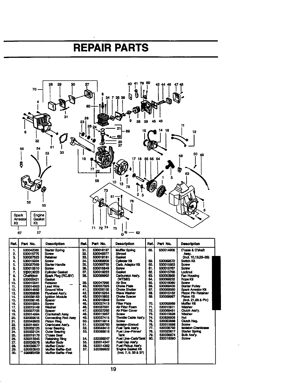
REPAIR PARTS
3O
I 1
6
56 54 51
67 57
33
9 38394543
17 18 65 66 64 5_0
71 72 74 75 !!__ 62
Ref. Part NO.
1. 530042085
2. 53001b'775
3. 530G_523
4. 533O15g_14
S. 5300275_
6. _ 530015810
11. 530014_3
12. 5300146_2
13. 53O06_86
14. 5300_)163
15. 530_6145
16. 5,30015954
17. 5300t514,9
18. 530_T/G5
I_ 530O14864
20. 530069615
21, 53004990_
122. 530014861
_124
LeadWlm
G_ _
Cr_W_,
MullerCover
Ba_e-Ex_
MuffetB_-_
RM. Pitt No.
31. 530O16197
32. $3O04_7
$3O01_81
34. 53006_eOe
35. 59O069758
36. 58O015849
37. 533O1_Q23
38. 53006_g_2
• 4_. $300479_
41. 5,.q003810_
42. 533O15254
SS0015eS2
44. 530015849
45. 530_7413
46. ,S,.q00_331
47. 53O0372_
48. 530015957
49. 530037415
50. 530015814
51. 5300_/93
630049413
S3 ,S3006_ 8
5_ 53006_47
55._ 530014347
56. S300143_
57. 53006_2
Deecrl_on
19
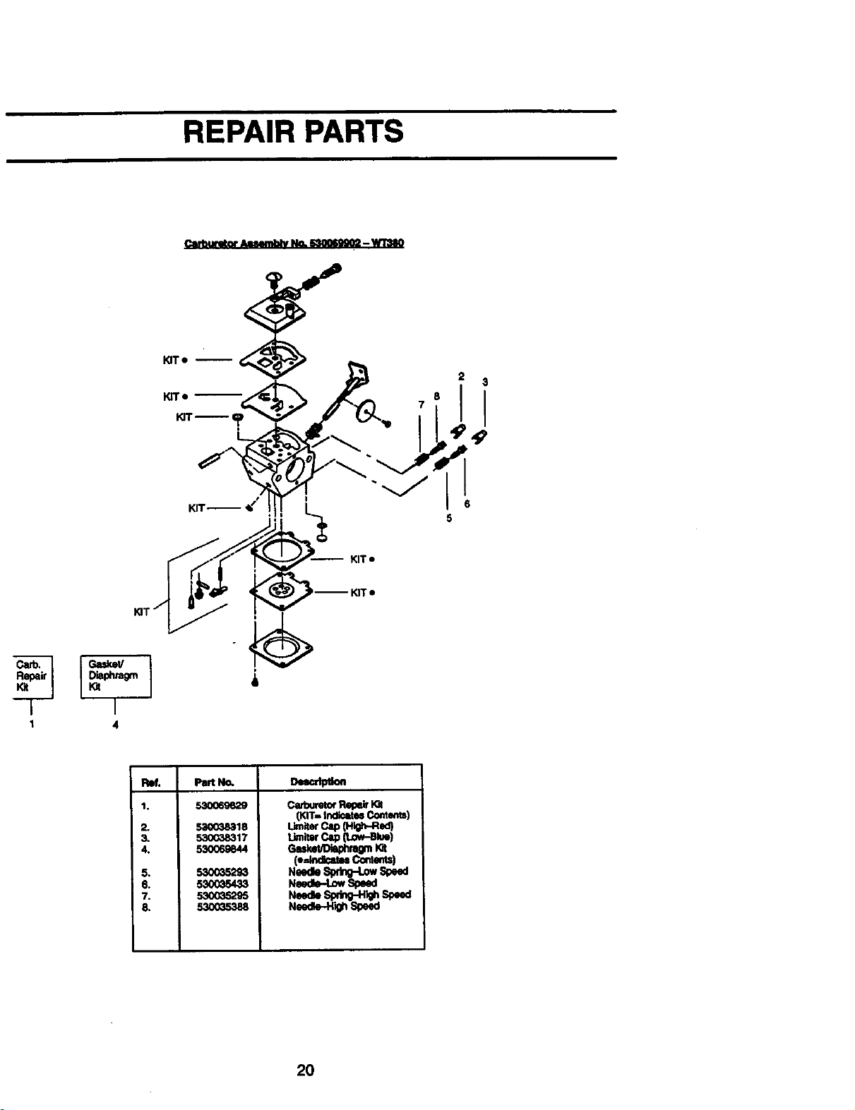
REPAIR PARTS
5
KIT •
Carb.
I
r
4
I, 530069629
2.
3.
4.
5,
$.
7.
8.
53003_18
530_8317
530O69844
5300352_
53OO35433
53O035295
530035388
_ P,m_m
(KIT,, Ind_tu Comenm)
umJtercap0_,-R_')
UmiterCap0.o+-mue)
N_
2O

YOUR WARRANTY RIGHTS AND OBLIGA-
TIONS: The U. S. EnvironPasntaLProt_rc_on
Agency/CallfomisAir Resources Board and
SEARS, ROEBUCKAND CO.,me pleasedto
exp_aintheen_ssi_s qpntrotsystem.war(an-
tyonyourlawnanagaraanequIpmemengine:
AllneWutilityand lawnand garaenequipmem
engines must be designed, built, and
equipped to meet the stringent anti-smog
standards. SEARS, ROEBUCK AND CO.
must warranttheemissioncontrol systemon
yourlawn and garcl,an equipment engine ror
thepe.dodsoftime dstedbemwpmvtaeamere
has been no abuse, neglect, or impmp.er
maintanance ofyourlawn and galen equ!p-
mantanglne.Your emlasloncomrolsystemp-
dudes parts such as the carburetorano me
ignition system.Where a wsnantabis cona_-
tionexits, BEARS, ROEBUCK AND CO. will
repair your lawn and i_zrdan equipment en-
gine atno cost.to you.P.xpens..escoverea .u.n-
der warrantyincludediagnosis,parts ano ta-
bor. MANUFACTURER'S WARRANTY
COVERAGE: Ifany emissionsrelatedparton
yourengine (as listedunder EmissionsC.on-
trolWarranty Parts Ust) is oefe_ve ora ae-
fectinthe matafialsor workmansnlpofmeen-
gne causes the failure of such an emission
related part, the part will be repaired or re-
placed by. SEARS, ROEBUCK AND CO.
OWNER S WARRANTY RESPONSIBILi-
TIES: Asthelawn and garden equipment en-
gineowner,youare responsiblef_the penor-
manca ofthe required maintenance listedin
your Owner's Manual. SEARS, ROEBUCK
AND CO. recommends that you retainall re-
caipts coveting malnter_mco on your lawn
and garden equipment engine, but _P_AH_,
ROEBUCK AND CO. cannot deny warranty
solelyforthe le,ckofreceiptsorforyourfailure
to ensure the performance of all scheduled
maintenance. As thelawn ariagaman equip-
mentengine owner,youshouldbeawarethat
SEARS, ROEBUCKAND CO. mayoeny you
warrahb_-cbverageif your lawn _ garden
equipmentengineor a pan orithasfallea oue
toabuse, nsgisct, lmpropermalntonance,un-
approvedmodificat_:)nsor_e u,se.ofpeulsnot
made or approvea oy me ongin_, equipmenz
manufacturer. You are responsible;or pres-
entingyour lawn and gar_len.equipmenten-
gineto a SEARS Service uenrer as soon_ a
problem exists, warranty rap_drs,sn.._la oe.
completedinareasonableamountoftJme,noz
toexceed 30 days. Ifyou have anyquestions
regardingyourwarranty rightsand resp?nsi-
billties,you shouldcontact your nearest au-
thorized servicecenter or callSEARS, ROE-
BUCK AND CO. at 1-800-235-5878.
WARRANTY COMMENCEMENT DATE:
The warranty pedod begins on the date the
lawn and garoan equipmenteng|ne mpur-
chased. LENGTH OF COVERAGE. This
warran.,tyshallbeforapedodottwoyeersfrom
the nnitialdate of purchase. WHAT IS COV-
ERED: REPAIR OR REPLACEMENT OF
PARTS. Repair or replacement of _ war-
rantedpartwillbe performedat no charge,to
the owner at an approved SEARS Sennca
Center.Ifyou _ye _ ques_o_.,reg_iog
yourwarrantyrightsand raspum,_n.mes.,you
shouldcontactyour nearest authodzee ser-
vice canter or call SEARS, ROEBUCK AND
CO. at 1-800-235-5878 WARRANTY PE
RIOD:Anywarrantad partwhichienotsched-
uied for replacement as required mainte-
nanca,or whichisscheduledonly for regular
inspeclJontotheeffestof "repalrorreplanees
necessary"shall be warranted for 2 years.
AnywarrantedpartwhichIsscheduled,forre.
placementas required maintenance smmDe.
warrantedfor the periodoftimeupto the .rst
scheduled replacement pok_tfor that part:
DIAGNOSIS: The ownershallnotbechargso
for diagnosticlaborwhichleads to the deter.:
ruination that_ warranted part isdetecave a
the diagnostic work is performed at an ap-
proved SEARS Service Center. CONSE-
QUENTIAL DAMAGES: SEARS, ROE-
BUCK AND CO. maybeliablefor .dan_..ge..s" to
otherenginecomponentscaused byme fail-
ure of a warrantedpart stillunder warranty.
WHAT IS NOT COVERED: All failures
caused byabuse,neglect,or improparmain-
tenance are not covered.ADD-ON OR MO-
DIFIED PARTS:"Theuseofadd--onormoditisd
parts,cenbe for " a
able to cover failures of warranted parts
caused by the use of add-on or modified
parts. HOW TO FILE A CLAIM: If you have
any questionsmgardh_gyourwarrantydghte
and msponsibiEties,you shouldcontactyour
nearest authorized service center or ca,
SEARS, ROEBUCK AND CO. at
1-800235-5878. WHERE TO GE'F WAR-
RANTY SERVICE: Warrantyservices or re-
pairsshallbe providedat all SEARS Service
Centers. Call: 1-800-235-5878 MAINTE-
NANCE, REPLACEMENT AND REPAIR OF
EMISSION RELATED PARTS: Any SEARS,
ROEBUCK AND CO. approvedreplacement
pertused inthe performanceofany w_
maintenance or repair on emission remso
parts will be providedwithout charge to the
owner if thepart is under warranty. EMIS-
SION CONTROLWARRANTY PARTS MST: .
Carburetor,IgnitionSystem:.S._. Plug(..c?v-
ered up to n_aintanancescneaule), Ignmon
Module. MAINTENANCE STATEMENT: The
ownerlsmsponsiblefortheperfo..r...m_,.,ofall
requiredmaintenance asoe.ned Inme own-
er's manual.

For the repair or replacement parts you need
delivered directly to Yourhome
Call 7 am - 7 pm, 7 days a week
1-800-366-PART ....
(!-800-366-7278)
Para ordenar piezas con entrega a
domicilio - 1-800-659-7084
For in-house major brand repair service
Call 24 hours a day, 7 days a week
1-800-4-REPAIR
(1-800-473-7247)
Para pedir servicio de reparaci6n a
domicilio - 1-800-676-5811
For the location of a Sears Parts and
Repair Center in your area
Call 24 hours a day, 7 days a week
1-800-488-1222
=_ ......
For information on purchasing a Sears
Maintenance Agreement or to inquire
about°a_-existing Agreement
Call 9 am - 5 pm, Monday-Saturday
1-800-827-6655
When requesting service or ordering
parts, always provide the following
information:
: Product Type • Part Number
Model-Number • Part Description
SEARS
America's Repair Specialists