Loading ...
Loading ...
Loading ...
SECTION 4 - MOWER ATTACHMENT SERVICE
4.4 CUTTER DECK BELT REMOVAL &
INSTALLATION
4.4.1. 36" CUTTING DECK BELT REMOVAL
1. Move Mower onto a smooth, level surface. Turn
Ignition Key to STOP position, remove Key,
disconnect Spark Plug Wire and secure Wire away -',7/
from Spark Plug.
2. Remove Mower deck belt cover.
3. Remove Idler Tension Spring and swing Idler away
from belt.
4. Remove old belt from Spindle Pulleys and Electric
Ctutch Pulley. See Figure 4.6.
REMOVE
,_- -?, ELECTRIC CLUTCH
IDLER
FIGURE 4.6
4.4.2, 36" CUTTING DECK BELT INSTALLATION
1. Route new belt to Electric Clutch Pulley.
2, Route new belt around Spindle Pulleys as shown in
Figure 4.6.
3. Move Idler against belt and reattach Idler Tension
Spring.
4.4.3. 48", 62", & 61" CUTTING DECK BELT
REMOVAL
1. Move Mower onto a smooth, level surface. Turn
Ignition Key to STOP position, remove Key,
disconnect Spark Plug Wire and secure Wire away
from Spark Plug.
2. Remove Mower deck belt cover.
3. Remove right hand Idler Tension Spring and swing
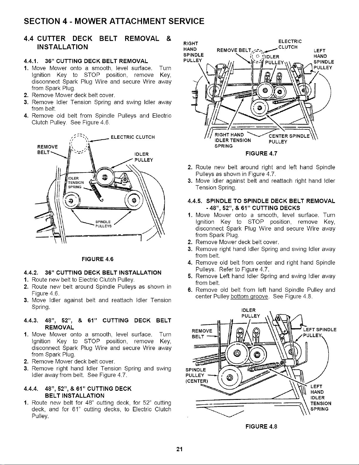
Idler away from belt. See Figure 4.7.
4.4.4. 48", 62", & 61" CUTTING DECK
BELT INSTALLATION
1. Route new belt for 48" cutting deck, for 52" cutting
deck, and for 61" cutting decks, to Electric Clutch
Pulley.
RIGHT
HAND
SPINDLE
PULLEY
\
ELECTRIC
REMOVE BELT,_".--.';_... ''_ CLUTCH
__ "_"_ pCuLLE&y,, , ,.__.. _.
/_ E_D _"_ENTER SPINDLE '
IDLER TENSION PULLEY
SPRING
FIGURE 4.7
LEFT
HAND
SPINDLE
PULLEY
?
2. Route new belt around right and left hand Spindle
Pulleys as shown in Figure 4.7.
3. Move Idler against belt and reattach right hand Idler
Tension Spring.
4.4.5. SPINDLE TO SPINDLE DECK BELT REMOVAL
-48", 62", & 61" CUTTING DECKS
1. Move Mower onto a smooth, level surface. Turn
Ignition Key to STOP position, remove Key,
disconnect Spark Plug Wire and secure Wire away
from Spark Plug.
2. Remove Mower deck belt cover.
3. Remove right hand Idler Spring and swing Idler away
from belt.
4. Remove old belt from center and right hand Spindle
Pulleys. Refer to Figure 4.7.
6. Remove Left hand Idler Spring and swing Idler away
from belt.
6. Remove otd belt from left hand Spindle Pulley and
center Pulley bottom qroove. See Figure 4.8.
IDLER
PULLEY
REMOVE
BELT
LEFT SPINDLE
SPINDLE
PULLEY
(CENTER)
LEFT
HAND
IDLER
TENSION
SPRING
FIGURE 4.8
21
Loading ...
Loading ...
Loading ...