Loading ...
Loading ...
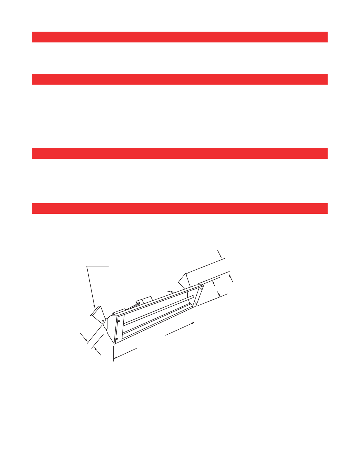
MOUNTING INSTRUCTIONS
These models may be chain or bracket mounted to any ceiling or horizontal surface. Installation must be such that
18" minimum clearance is maintained around the heater in front of the plane of the face. 6" of clearance provided by
mounting brackets is required behind the plane of the face.
WALL OR CEILING SWIVEL
MOUNTING BRACKETS (PAIR)
WALL
CEILING
60º MAX.
60º MAX.
AIM POINT
INSULATED HOUSING
6" MOUNTING SURFACE
TO REAR OF HEATER
8" WIDE
LENGTH VARIES
DEPENDING ON
MODEL (MAX.
61-1/4")
3”
ASSEMBLY INSTRUCTIONS
WIRING INSTRUCTIONS
OUTDOOR INSTALLATION
This heater must be permanently installed and hard wired by a licensed electrician. Assembly procedure must be per-
formed with no electrical power to unit.
Step 1: Remove cover plate from junction box.
Step 2: Attach conduit.
Step 3: Use only copper or aluminum wire suitable for 90°C.
Step 4: Replace cover plate.
Step 5: Observe local electrical code regulations.
Step 1: Heater must be mounted with reflector angled down.
Step 2: All electrical connections must be in compliance with the National Electric Code and local codes for outdoor wiring.
Step 3: Use only wiring components UL/CE listed for outdoor use with IP X 4 minimum rating.
3
Wall/ceiling brackets are furnished with all heaters. Their use is optional. When used, they allow heater to be fastened
to wall or ceiling and then tipped up to 60°. Heater can also be hung in a horizontal position using chains or custom
brackets. Heater must be level, but can be rotated around its horizontal axle.
Loading ...
Loading ...
Loading ...