
Integrated LED Light Module
Replacement
Repair Parts 041-0200-000, 041-0201-000,
041-0202-000 and 041-0203-000
To prevent possible SERIOUS INJURY or DEATH:
• Disconnect ALL electric and battery power BEFORE performing ANY
service or maintenance.
To prevent damage to the receiver logic board, DO NOT touch printed
circuit board of replacement receiver/logic board during installation.
ALWAYS wear protective gloves and eye protection when changing the
battery or working around the battery compartment.
WARNING: This product can expose you to chemicals including
lead, which are known to the State of California to cause cancer or
birth defects or other reproductive harm. For more information go to
www.P65Warnings.ca.gov.
Introduction
Use this instruction to replace the integrated LED light module. The images
throughout this manual are for reference only and your product may look
different.
You will need:
• 1/4" magnetic nut driver
• Long-nosed pliers
• 5/16" long-shafted magnetic nut driver and socket
• Flathead screwdriver
Instructions
1. Disconnect the electrical and battery power (if applicable) to the garage
door opener. Remove the battery and place in a safe location.
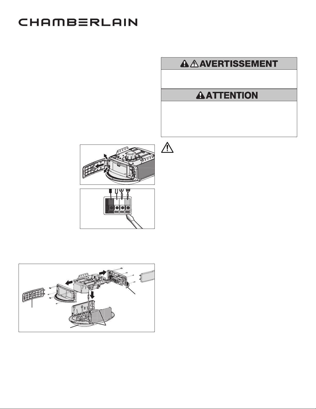
2. Remove the control door panel from both ends of
the opener. (A)
a. Separate the hinges in
opposite directions.
b. Remove the panels from
the hinge setting and
place in a safe location.
3.
Disconnect the door control
wires from the RED and
WHITE terminals and the
safety reversal sensor wires
from the BLACK and WHITE
terminals. (B)
4. Remove the end panels from
both ends of the opener.
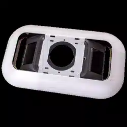
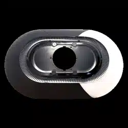
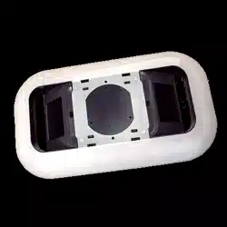
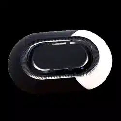
5. Remove the integrated LED
light module from the
opener. (C)
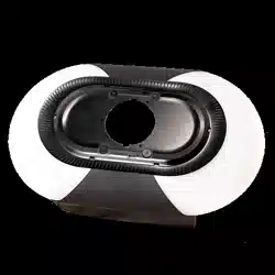
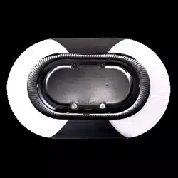
6. Disconnect the ORANGE and WHITE wire harness from plug to the
integrated LED light module and set aside cover / LED light module. (D)
7. Install the new integrated LED light module.
8. Connect the ORANGE and WHITE wire harness from the plug to the
Integrated LED Light Module. (D)
9. Align integrated LED light module to chassis screw holes.
10. Attach both end panels.
11. Reconnect the door control and safety reversal sensor wires. (B)
Door Control:
• WHITE wire into the WHITE terminal.
• WHITE/RED wire into the RED terminal.
Safety Reversal Sensors:
• WHITE wires into the WHITE terminal.
• WHITE/BLACK wires into the GRAY terminal.
12. Reattach the control door panels.
13. Reconnect power to the opener.
14. Test the Protector System.
RED
WHITE
WHITE
GREY
B
A
D
C
Integrated LED Light Module
Control Door Panel
End Panel

© 2021, Chamberlain
All rights reserved
Tous droits réservés
114-5536-000 Todos los derechos reservados
Remplacement du module intégré
d’éclairage à DEL
Pièces détachées 041-0200-000, 041-0201-000,
041-0202-000 et 041-0203-000
Pour éviter d’éventuelles BLESSURES GRAVES voire FATALES:
• Débranchez TOUTE l’alimentation secteur et de la batterie AVANT
d’effectuer TOUT service ou entretien.
Pour éviter d’endommager la carte mère du récepteur, ne touchez PAS le
circuit imprimé du récepteur/de la carte mère de remplacement pendant
l’installation.
Portez TOUJOURS des gants de protection et des lunettes de protection
lorsque vous changez la batterie ou que vous travaillez autour de son
compartiment.
®
®
AVERTISSEMENT: Ce produit peut vous exposer à des produits
chimiques, dont le plomb, qui sont reconnus par l’État de Californie
comme provoquant le cancer, des malformations congénitales ou
d’autres problèmes de reproduction. Pour plus d’information, visitez
www.P65Warnings.ca.gov.
Introduction
Utilisez ces instructions pour remplacer le module intégré d’éclairage à DEL.
Les images de ce manuel sont fournies à titre indicatif uniquement et il est
possible que votre produit soit différent.
Vous aurez besoin de ce qui suit:
• Tourne-écrou magnétique 1/4po
• Pinces à long bec
• Tourne-écrou magnétique à manche long 5/16po et douille
• Tournevis à tête plate
Instructions
1. Débranchez l’alimentation électrique et la batterie (le cas échéant) de
l’ouvre-porte de garage. Retirez la batterie et mettez-la dans un endroit sûr.
2. Retirez le panneau de la porte de commande de chaque côté de l’ouvre-
porte. (A)
a. Séparez les charnières dans les directions opposées.
b. Retirez les panneaux de
l’emplacement de leurs
charnières et mettez-les
dans un endroit sûr.
3. Débranchez les fils de
commande de la porte des
bornes ROUGE et BLANCHE et
les fils du capteur d’inversion
de sécurité des bornes NOIRE
et BLANCHE. (B)
4. Retirez le panneau
d’extrémité de chaque côté
de l’ouvre-porte.
5. Retirez le module intégré
d’éclairage à DEL de l’ouvre-
porte. (C)
6. Débranchez le faisceau de câbles ORANGE et BLANC de la prise du module
intégré d’éclairage à DEL et mettez le couvercle/module d’éclairage à DEL
de côté. (D)
7. Installez le nouveau module intégré d’éclairage à DEL.
8. Connectez le faisceau de câbles ORANGE et BLANC de la prise au module
intégré d’éclairage à DEL. (D)
9. Alignez le module intégré d’éclairage à DEL sur les trous de vis du cadre.
10. Remettez en place les deux panneaux d'extrémité.
11. Reconnectez les fils de la commande de porte et du capteur d’inversion de
sécurité: (B)
Contrôle de porte:
• Fil BLANC dans la borne BLANCHE.
• Fil BLANC/ROUGE dans la borne ROUGE.
Capteurs d’inversion de sécurité:
• Fils BLANCS dans la borne BLANCHE.
• Fils BLANCS/NOIRS dans la borne GRISE.
12. Remettez en place le panneau de la porte de commande.
13. Rebranchez l’alimentation à l’ouvre-porte.
14. Testez le système de protection.
ROUGE
BLANC
BLANC
GRIS
B
A
D
C
Module intégré d’éclairage à DEL
Panneau de la porte
de commande
Panneau d’extrémité

© 2021, Chamberlain
All rights reserved
Tous droits réservés
114-5536-000 Todos los derechos reservados